Bryton orporation CA1505 GPS enabled cycling computer User Manual 4
Bryton Incorporation GPS enabled cycling computer Users Manual 4
Contents
- 1. Users Manual-1
- 2. Users Manual-2
- 3. Users Manual-3
- 4. Users Manual-4
Users Manual-4
CADENCESPEED
SPEED
SPEED
3
mm
SPEED
SPEED
SPEED
SPEED
Speed
Turn Off
Status: active
ID XXXXXXXXX
Rescan
SPEED
Speed
Turn Off
Status: active
ID XXXXXXXXX
Rescan
Cadence
Turn Off
Status: active
ID XXXXXXXXX
Rescan
1
2
3
4
5a
6a
7a
8a
5b
6b
7b
8b
Cadence
Turn Off
Status: active
ID XXXXXXXXX
Rescan
3
mm
CADENCE
Speed/CAD
Turn Off
Status: active
ID XXXXXXXXX
Rescan
5c
6c
7c
8c
Speed/CAD
Turn Off
Status: active
ID XXXXXXXXX
Rescan
3
mm
ENGLISH
Appendix 28
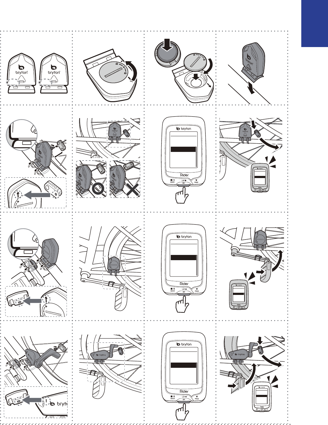
Install the Speed/Cadence/Dual Sensor
(Optional)
Appendix
29
NOTE:
To ensur• e optimum performance, do the following:
- Align both sensor and magnet as shown in the illustration (5a / 5b). Pay attention on the
alignment points.
- Ensure the distance between the sensor and the magnet is within 3 mm.
Ensure that both Speed sensor and Speed magnet are installed and aligned horizontally, •
not vertically.
On the initial usage, press the front button to activate the sensor and start pedaling. •
When the sensor detects the magnet, the LED blinks once to indicate the alignment is
correct (the LED blinks only for the rst ten passes after pressing the button).
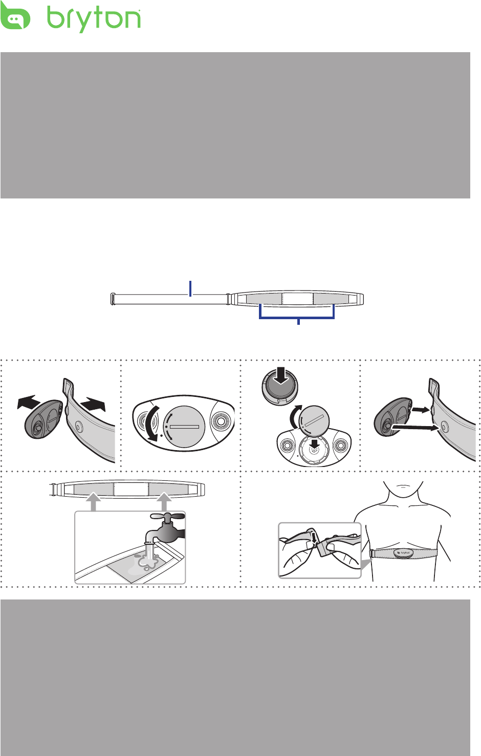
Install Heart Rate Belt (Optional)
Electrodes
Strap
C
L
O
S
E
O
P
E
N
C
L
O
S
E
O
P
E
N
C
L
O
S
E
O
P
E
N
1
2
3
4
5
6
C
L
O
S
E
O
P
E
N
NOTE:
In cold weather, wear appropriate clothing to keep the heart rate belt warm.•
The belt should be worn directly on your body.•
Adjust the sensor position to the middle part of the body (wear it slightly below the •
chest). The Bryton logo shown on the sensor should be facing upward. Tighten the elastic
belt rmly so that it will not turn loose during the exercise.
If the sensor cannot be detected or the reading is abnormal, please warm up for about 5 •
minutes.
If the heart rate belt is not used for a period of time, remove the sensor from the heart •
rate belt.
ENGLISH
Appendix
30
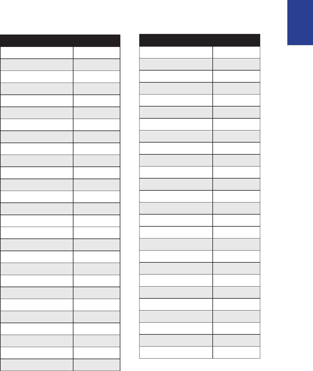
Wheel Size and Circumference
The wheel size is marked on both sides of the tires.
Wheel Size L (mm)
24 x 1.75 1890
24 x 2.00 1925
24 x 2.125 1965
26 x 7/8 1920
26 x 1(59) 1913
26 x 1(65) 1952
26 x 1.25 1953
26 x 1-1/8 1970
26 x 1-3/8 2068
26 x 1-1/2 2100
26 x 1.40 2005
26 x 1.50 2010
26 x 1.75 2023
26 x 1.95 2050
26 x 2.00 2055
700 x19C 2080
700 x 20C 2086
700 x 23C 2096
700 x 25C 2105
700 x 28C 2136
700 x 30C 2170
700 x 32C 2155
700C Tubular 2130
700 x 35C 2168
700 x 38C 2180
700 x 40C 2200
Wheel Size L (mm)
12 x 1.75 935
14 x 1.5 1020
14 x 1.75 1055
16 x 1.5 1185
16 x 1.75 1195
18 x 1.5 1340
18 x 1.75 1350
20 x 1.75 1515
20 x 1-3/8 1615
22 x 1-3/8 1770
22 x 1-1/2 1785
24 x 1 1753
24 x 3/4 Tubular 1785
24 x 1-1/8 1795
24 x 1-1/4 1905
26 x 2.10 2068
26 x 2.125 2070
26 x 2.35 2083
26 x 3.00 2170
27 x 1 2145
27 x 1-1/8 2155
27 x 1-1/4 2161
27 x 1-3/8 2169
650 x 35A 2090
650 x 38A 2125
650 x 38B 2105
700 x 18C 2070

Appendix
31
Basic Care For Your Rider 320
Taking good care of your device will reduce the risk of damage to your device.
Do not drop your device or subject it to severe shock.•
Do not expose your device to extreme temperatures and excessive moisture.•
The screen surface can easily be scratched. Use the non-adhesive generic screen •
protectors to help protect the screen from minor scratches.
Use diluted neutral detergent on a soft cloth to clean your device.•
Do not attempt to disassemble, repair, or make any modications to your device. Any •
attempt to do so will make the warranty invalid.
NOTE: Improper battery replacement may cause an explosion. When replacing a
new battery, use only the original battery or a similar type of battery specied by the
manufacturer. Disposal of the used batteries must be carried out in accordance to the
regulations of your local authority.
For better environmental protection, waste batteries should be collected
separately for recycling or special disposal.

Screen Terminologies
Screen Display Terminology
LapAvSpd lap average speed
LapMaSpd lap maximum speed
L'stLpAvSp last lap average speed
LapDist lap distance
L'stLpDist last lap distance
L'stLapT last lap time
LapAvHR lap average heart rate
LapMaHR lap maximum heart rate
L'LpAvHR last lap average heart rate
L'A'MHR% lap average MHR percentage
L'A'LTHR% lap average LTHR percentage
Str'dRate stride rate
AvStr'dRt average stride rate
MaStr'dRt maximum stride rate
LpAvSt'dR lap average stride rate
LpStr'dAvL lap stride average length
LLpSt'dAvL last lap stride average length
AvSt'dl'gth average stride length
AvgPace average pace
MaxPace maximum pace
L'st1kmP last 1km/mile pace
LapAvP lap average pace
L'stLpAvP last lap average pace
LapMaP lap maximum pace
LAvCAD lap average cadence
ODO odometer
T to Dest Time to Destination
D to Dest Distance to Destination
Alt. Gain Altitude Gain
Alt. Loss Altitude Loss
Appendix 32

Screen Display Terminology
Sunrise sunrise time
Sunset sunset time
Avg Speed average speed
Max Speed maximum speed
HR heart rate
Avg HR average heart rate
Max HR maximum heart rate
MHR Zone maximum heart rate zone
Avg CAD average cadence
Max CAD maximum cadence
LLAvCAD last lap average cadence
3s Power 3 seconds average power
30s Power 30 seconds average power
LLapMaxPW
LapMaxPW lap maximum power
last lap maximum power
Avg Power average power
LapAvgPW lap average power
LLapAvgPW last lap average power
MAP Zone Maximum Aerobic Power Zone
MAP% Maximum Aerobic Power Percentage
FTP Zone Functional Threshold Power
FTP% Functional Threshold Power Percentage
PS L-R Left and Right Pedal Smoothness
TE-LR Left and Right Torque Eectiveness
PB L-R Left and Right Power Balance
Avg PS-LR Average Left and Right Pedal Smoothness
Avg TE-LR Average Left and Right Torque Eectiveness
Avg PB L-R Average Left and Right Power Balance
Max PS-LR
Max TE-LR
Max PB-LR
Maximum Left and Right Pedal Smoothness
Maximum Left and Right Torgue Eectiveness
Maximum Left and Right Power Balance
Federal Communication Commission Interference Statement
This equipment has been tested and found to comply with the limits for a Class B
digital device, pursuant to Part 15 of the FCC Rules. These limits are designed to
provide reasonable protection against harmful interference in a residential installation.
This equipment generates, uses and can radiate radio frequency energy and, if not
installed and used in accordance with the instructions, may cause harmful interference
to radio communications. However, there is no guarantee that interference will not
occur in a particular installation. If this equipment does cause harmful interference to
radio or television reception, which can be determined by turning the equipment off
and on, the user is encouraged to try to correct the interference by one of the
following measures:
. Reorient or relocate the receiving antenna.
. Increase the separation between the equipment and receiver.
. Connect the equipment into an outlet on a circuit different from that to which the
receiver is connected.
. Consult the dealer or an experienced radio/TV technician for help.
FCC Caution: To assure continued compliance, any changes or modifications not
expressly approved by the party responsible for compliance could void the user's
authority to operate this equipment. (Example - use only shielded interface cables
when connecting to computer or peripheral devices).
FCC Radiation Exposure Statement
This equipment complies with FCC RF radiation exposure limits set forth for an
uncontrolled environment. This equipment should be installed and operated with a
minimum distance of 0.5 centimeters between the radiator and your body.
This transmitter must not be co-located or operating in conjunction with any other
antenna or transmitter.
The antennas used for this transmitter must be installed to provide a separation
distance of at least 0.5 cm from all persons and must not be co-located or operating in
conjunction with any other antenna or transmitter.
This device complies with Part 15 of the FCC Rules. Operation is subject to the
following two conditions:
(1) This device may not cause harmful interference, and (2) This device must accept
any interference received, including interference that may cause undesired operation
Industry Canada Statement
This device complies with Industry Canada licence-exempt RSS standard.
Operation is subject to the following two conditions: (1) this device may not cause
interference, and (2) this device must accept any interference, including interference
that may cause undesired operation of the device.
Le présent appareil est conforme aux CNR d'Industrie Canada applicables aux
appareils radio exempts de licence. L'exploitation est autorisée aux deux conditions
suivantes : (1) l'appareil ne doit pas produire de brouillage, et (2) l'utilisateur de
l'appareil doit accepter tout brouillage radioélectrique subi, même si le brouillage est
susceptible d'en compromettre le fonctionnement.
IC Radiation Exposure Statement:
This equipment complies with IC RSS-102 radiation exposure limit set forth for an
uncontrolled environment. This equipment should be installed and operated with
minimum distance 0.5 cm between the radiator and your body.