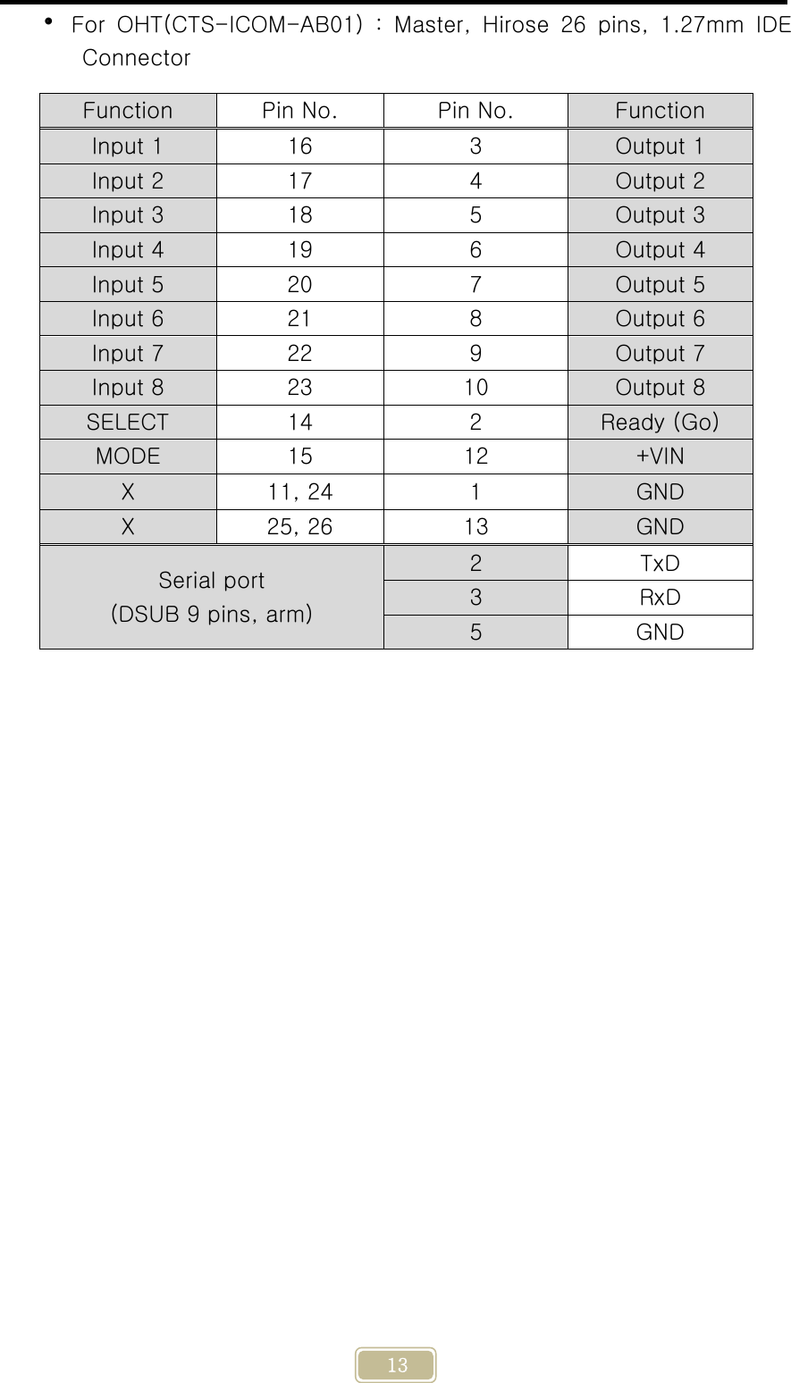
CANTOPS CTS-ICOM IR PIO User Manual Appendix 8

CanTops IR PIO Appendix 8

Users Manual

    1     CTS-ICOM-AA01 (EQ-PIO) CTS-ICOM-AB01 (OHT-PIO)         * The wireless equipment concerned can result in jamming during operation. 2014. 3. 11 ( Ver 0.9 )    IR-PIO SPECIFICATION
    2  FCC STATEMENT This device complies with part 15 of the FCC Rules. Operation is subject to the following two conditions: (1) this device may not cause harmful interference,  and  (2)  this  device  must  accept  any  interference  received, including interference that may cause undesired operation.  FCC ID: RMNCTS-ICOM  WARNING!    Changes or  modifications  to  this  unit  not  expressly  approved by the party responsible for compliance could void the user’s authority to operate the equipment.  RF  EXPOSURE  WARNING!  This  equipment  must  be  installed  and  operated in accordance with provided instructions and the antenna(s) used for this transmitter must be installed to provide a separation distance of at least 20 cm  from  all  persons  and  must  not  be  co-located  or  operating  in conjunction with any other antenna or transmitter. End-users and installers must  be  provided  with  antenna  installation  instructions  and  transmitter operating conditions for satisfying RF exposure compliance.  Note: This equipment has been tested and found to comply with the limits for a Class B digital device, pursuant to part 15 of the FCC Rules. These limits  are  designed  to  provide  reasonable  protection  against  harmful interference  in  a  residential  installation.  This  equipment  generates,  uses and  can  radiate  radio  frequency  energy and, if not installed and  used  in accordance with the instructions, may cause harmful interference to radio communications. However, there is no guarantee that interference will not occur  in  a  particular  installation.  If  this  equipment  does  cause  harmful interference to radio or television reception, which can be determined  by turning the equipment off and on, the user is encouraged to try to correct the interference by one or more of the following measures: —Reorient or relocate the receiving antenna. —Increase the separation between the equipment and receiver. —Connect the equipment into an outlet on a circuit different from that to which the receiver is connected. —Consult the dealer or an experienced radio/TV technician for help.
    3  [ Table of Contents ]  1. Product Outline 2. Product Feature 3. Wireless Communication Characteristics 4. IR Communication Characteristics 5. Product Code Configuration 6. IR Radiation Characteristics 7. Antenna Radiation Characteristics 8. Input/output Circuit 9. Product Specification 10. Tool Specification 11. Connector Connection Specification 12. LED Display Content 13. Major Pin Function 14. ID & CH Setting Method 15. RF Consideration When Installing a PIO
    4  1. Product Outline The CTS-ICOM Series is an IR communication device used  to  give  and receive  8-bit  data  in  a  non-contact  type,  and  is  a  product  with various convenient functions using a 2.4GHz wireless communication technology. This  device  is  used  to  give  and  receive  a  SEMI-E84/E23 protocol  or maximum  8-bit  input/output  data  wirelessly  for  an  exchange  of  control signals mainly between an AGV or OHT(Master or Active device), etc. and equipment(Slave or Passive device). This is a product to grasp causes quickly and establish measures easily by providing various functions to analysis the causes in case of  an abnormality in data given and received during use.  2. Product Feature  IR communication : For giving and receiving input/output data   2.4GHz  wireless  communication  :  Additional  function  such  as downloading of transmission/reception data and F/W, etc.  The wireless communication operating distance is maximum 5M (However,  there  shall  be  no  obstacles  to  electromagnetic  waves  in the middle.)  Designation of a wireless communication ID(address) : 6 digits (hexadecimal code)  For 8-bit input/output signals  Storage of various information using a large-capacity SRAM : About 200 pieces of work such as communication data, absolute time, reception signal intensity, etc. (Erased when power is OFF)   Serial  communication  port  :  Setting  change,  communication  data information receiving, F/W downloading, etc.     3. Wireless Communication Characteristics  RF communication using a 2.4GHz ISM(Industrial,  Scientific  and  Medical) band that can be used without permission  Equipment name: Wireless device for a wireless data communication system  High-speed data communication of 1Mbps per channel  GFSK modulation type, 1MHz bandwidth
    5  Superior expandability with an optional function of 6-byte serial number and 2-byte frequency     200uS  or  less  channel  switching  time  to  minimize  interference with other wireless devices  Possibility of frequency interference with 2.4GHz Bluetooth and wireless communication devices  RF maximum output power : 0dBm  Sensitivity of the reception part : -90dBm
    6 4. IR Communication Characteristics  Wavelength : 870nm (infrared ray)  Ambient brightness : 4000lx or less incandescent lamp and fluorescent lamp, where there is no direct sunshine  Transmission and reception method : Half Duplex  Modulation method : Pulse Modulation  Operating distance and angle : 0.5m at 0°, 0.25m at  ±15°  Communication distance regulation : Serial communication command   Reception  level  regulation  :  For  serial  communication  command  and ambient light noise removal   Input  signal  and  GO  output  filtering  function  :  0th ~ 10th (Serial communication command)  5. Product Code Configuration Item name  Feature CTS-ICOM-AA01-xx-y-zz (EQ, Slave) 25-pin DSUB, Male Type (For equipment) CTS-ICOM-AB01-xx-y-zz (OHT, Master) Hirose 26-pin, HIF6-26D-1.27R (For OHT, AGV) *) xx : The communication distance and unit are 0.1m, 05=0.5m, 10=1.0m *) y : Transmission and reception window position, T=Top View, F=Front View *) zz : The cable length and unit are 0.1m, 25=2.5m
    7 6. IR Radiation Characteristics As  shown  in  the  figure  below,  the  communicable  angle  is  30°,  and communication is possible from a 0.25m away distance at  ±15°  and from a 0.5m away distance at 0°. If lighting, sunshine, IR remote control, IR type sensor, etc. applies light directly to the transmission and reception window, then there may happen loss of communication. In this case, shield  the external light and then use it.  7. Antenna Radiation Characteristics The antenna used for this product is located at the position like the figure below in the case. In order to exert the maximum performance without jamming,  the  whole  product  except  the  fixing  hole  part  had  better  be arranged such that there may be no object that can cause jamming. Especially,  avoid  metals  or  other  objects  that  can  cause  jamming  around the antenna.     IN 1 2 3 4 5 6 7 8 GOSTATEOUTFixing hole(2 ea) Antenna 0.25m +15°-15°0.5m
    8 8. Input/output Circuit  Input circuit : Maximum 10mA                  Output circuit : NPN type Open Collector, maximum operating current of 50mA / 30V                  VCE    max. 100mV / 10mA                  RF-PIOInsideINPUT+24V VCCRF-PIOInsideOUTPUTDCVPIO Inside PIO Inside
    9 9. Product Specification Division  Specific item  Content Display part GO  Displayed  when  IR  communication starts STATE  Flashing  as  watchdog  signals  for operating conditions IN  Display  of  operating  conditions  of the 8Bit input port OUT  Display  of  operating  conditions  of the 8Bit output port External equipment connection Connection connector AA01  Model  :  25-pin  DSUB,  Male, 2.5m, 5m AB01  Model  :  Hirose  26-pin, 1.27mm pitch, 1m Cable  26AWG  x  22C  +  24AWG  x  3C,  Foil Shield Input  8 Bit, Photo-Coupler, 24V On : 10mA, Off : 0.1mA or less Output  8Bit, Open Collector, NPN, 30V Maximum operating current 50mA IR Communication function Communication media  870nm, Infrared Communication distance  0.5m (0°), 0.25m (+15°, -15°) Communication angle  30°  ( ±15°) Communication method  1:1 communication, Half Duplex Communication window location T Type : Top View F Type : Front View Optical modulation type Pulse Modulation Communication error check  Parity Communication period About  24ms  when  linked,  about 48ms when communication is lost Additional communication(RF) function Communication media  2403~2480 MHz, bandwidth 1MHz Frequency band  2403~2480 MHz, 78 channels*1) Safety function Serial number confirmation function, CRC-16
    10 Communication type  1:1 communication, Half Duplex ID setting PIO  serial  number  to  avoid interference  with  neighboring  PIOs, which  is  composed  of  16 digits(hexadecimal code) Channel settingCommunication  frequency  to  avoid interference  with  neighboring  PIOs, which is composed of 3 digits ID setting method  Serial communication command Major function  F/W download, data download, time setting, etc. Operating distance 5m@0dBm(However,  when  there  is no  objects  causing  jamming  in  the middle) Environment Storage environment Storage temperature : -25 ~ 70°C Storage humidity : 5 ~ 95%RH (However,  there  shall  be  no  dew condensation phenomenon) Operating environment Ambient  brightness  :  4000lx  or  less (Incandescent  lamp,  fluorescent lamp) *)  Install  it  such  that  no  external light may enter the reception part. Operating temperature : 0 ~ 40°C Operating  humidity  :  35~85  %RH (However,  there  shall  be  no  dew condensation phenomenon) Vibration  :  4~150  Hz,  4.9m/s2 or less Power Input voltage  DC 24V±10% Consumed current  100mA or less @ 24V Case material  Polycarbonate Size(WHD)  505320mm (Except the connector overhang)   Weight  About 100g *1) Can be used in an environment without frequency interference with other wireless equipment(wireless LAN, Bluetooth, etc.)
    11 10. Tool Specification   < F Type : Front View >                 < T Type : Top View >      Unit: mm
    12 11. Connector Connection Specification  For equipment(CTS-ICOM-AA01) : For equipment(Slave), DSUB 25 pin, Pin Type, cable length 2.5m, 5m  The Mode pin(#11) is connected to GND in the product, so it doesn’t need to be connected.                Function  Pin No.  Function  Pin No. IN 1  1  OUT 1  14 IN 2  2  OUT 2  15 IN 3  3  OUT 3  16 IN 4  4  OUT 4  17 IN 5  5  OUT 5  18 IN 6  6  OUT 6  19 IN 7  7  OUT 7  20 IN 8  8  OUT 8  21 Not Connected  9  Not Connected 22 SELECT  10  +VIN  23 MODE  11 (GND)  GND  24 Go (Ready)  12  GND  25 Not Connected  13    x  x Serial port (DSUB 9 pins, arm) TxD  2 RxD  3 GND  5
    13  For OHT(CTS-ICOM-AB01) : Master, Hirose 26 pins, 1.27mm IDE Connector                    Function  Pin No.  Pin No.  Function Input 1  16  3  Output 1 Input 2  17  4  Output 2 Input 3  18  5  Output 3 Input 4  19  6  Output 4 Input 5  20  7  Output 5 Input 6  21  8  Output 6 Input 7  22  9  Output 7 Input 8  23  10  Output 8 SELECT  14  2  Ready (Go) MODE  15  12  +VIN X  11, 24  1  GND X  25, 26  13  GND Serial port (DSUB 9 pins, arm) 2  TxD 3  RxD 5  GND
    14 12. LED Display Content               LED name  Display content 1~8 The IN side displays the input condition, which is turned ON when the Low is inputted. The OUT side displays the output condition, which is turned ON when the TR is turned ON. GO Turned ON when data transmission/reception is realized between PIOs. Delay time until the GO LED is turned OFF after wireless transmission/reception is disconnected: The filtering can be set 2 ~ 20 times(48ms*The number of filtering times). STATE Used as watchdog signals to check whether there is an abnormality in this product or not, and the period of flashing differs depending on master mode(0.25 sec), slave mode(1 sec) or standby mode(0.05 sec). IN 1 2 3 4 5 6 7 8 GOSTATEOUTFixing hole(2 ea)
    15 13. Major Pin Function   Master Mode : Opening the Select signal and operating the PIO transmits optical signals. This is a mode attached to OHT or AGV and used.  Slave Mode : Even opening the Select signal and operating the PIO doesn’t transmit light, but only receives light, and then receiving optical signals from the master transmits the data entering the input port wirelessly. This is a mode attached to the equipment and used.      Signal name  Usage Mode (Input) Input to select a mode of PIO ▪  GND : Slave Mode (equipment) ▪  OPEN : Master Mode (OHT) Select (Input) Input to operate the PIO ▪  GND : PIO function stop ▪  OPEN : PIO operation GO (Output) Turned ON if communication is normally realized between the Master PIO and the Slave PIO
    16 14. ID & CH Setting Method The wireless function of CTS-ICOM Series is simultaneously connected to many devices due to its wireless characteristics to be  crossed, so in order  to  communicate  with  a  device,  the  ID  and  CH(channel)  of  the communication  counterparty  shall  be set before  starting  communication and then communication shall be tried. This ID and CH setting is possible using serial communication.   Slave Mode : Connect it to the serial port of this device, and then set the ID,  channel  and  transmission  power  to  use  by  using  a communication command. The set data is stored in EEPROM, so even though power is turned OFF after set once, it doesn’t need to be set again.   Serial communication setting value: 57600,8,n,1, no flow control  The starting letter for all commands is “<”, and the ending letter is “>”.  The starting letter for a reply to a command is “[“, and the ending letter is “]”.  The ID uses 6 digits and hexadecimal codes  <A> Command to change the address 1) Setting : <A=623456> 2) Confirmation : <A>Reply : [A=AB95-623456] 3) Setting value during shipment: 0000-000000 <B> Command to change the address and the channel at a time 1) Setting : <B=B54321:34> 2) Confirmation : <B>Reply[B=AB95-B54321:34]   3) Setting value during shipment: 0000-000000:00 <C> Command to set a channel 1) Setting : <C=40> 2) Confirmation : <C>Reply : [C=40] 3) Setting value during shipment: 00 <P> Command to set the transmission power 1) Setting : <P=3> 2) Confirmation : <P>Reply : [P=3] 3) Setting value during shipment: 3 <D> Command to receive real-time communication data in serial 1) Setting : <D=1> data output, <D=0> no output 2) Confirmation : <D>Reply : [D=0] 3) Setting value during shipment: 0
    17 <T> Command to set the time 1) Setting : <T=10/08/17 23:33:30> 2) Confirmation : <T>Reply : [T=10/08/17 23:33:41-2] 3) Setting value during shipment: 10/01/01 00:00:00 <V> Check the F/W version. 1) Confirmation : <V>Reply : [V=1.30]
    18 15. RF Consideration when Installing a PIO Intensity of electromagnetic wave : The length of the arrow in the figure below indicates the size of electromagnetic waves emitted from the PIO, so the electromagnetic waves are emitted the most to the up direction. Therefore, a structure facing a possible sensor end(green part, the area with an antenna) is the most desirable.    Caution 1) Metals, mirrors and other objects existing in a space at the straight-line distance  between  two  sensors  reduce  the  wireless  performance. Remove the obstacles on the wireless path as far as possible. 2) You can use it stably without communication errors when there  is  no interference with other wireless devices in an open space. 3) There is an antenna around the green part in the above figure. Take care so  that  there  may  be  no  metals  or  other  obstacles  within  a  60mm radius around this antenna. 4) There may happen frequency interference due to other RF devices around. Use this in an environment without frequency interference  for stable operation. 5) Especially, when using this together with a device using a 2.4GHz band, allocate a channel such that the used channels may not be overlapped. 6) Maintain an 20cm or more interval between PIOs for equipment that are installed in the equipment.    *)  The  specification  of  this  product  is  subject  to  changes  without  prior notice to improve the performance of the product.

Navigation menu