CARRIER Package Units(both Units Combined) Manual L0604564
User Manual: CARRIER CARRIER Package Units(both units combined) Manual CARRIER Package Units(both units combined) Owner's Manual, CARRIER Package Units(both units combined) installation guides
Open the PDF directly: View PDF ![]() .
.
Page Count: 28
HEATING & COOLING
Visit www.carrier.com
50JS, 50JX
3-Phase Single-Packaged Heat Pumps
Installation, Start-Up,
and Service Instructions
NOTE: Read the entire instrdction manual before starting the
installation.
TABLE OF CONTENTS
SAFETY CONSIDERATIONS ..................................................... 1
INTRODUCTION .......................................................................... 2
RECEIVING AND INSTALLATION .......................................... 2
Check Equipment ...................................................................... 2
IDENTIFY UNIT ................................................................ 2
INSPECT SIMPMENT ........................................................ 2
Provide Unit Support ................................................................ 2
ROOF CURB ....................................................................... 2
SLAB MOUNT ................................................................... 2
GROUND MOUNT ............................................................ 2
Provide Clearances .................................................................... 2
Rig and Place Unit .................................................................... 2
INSPECTION ...................................................................... 2
INSTALLATION ................................................................ 2
Select and Install Ductwork ..................................................... 4
CONVERTING HORIZONTAL DISCHARGE UNITS TO
DOWNFLOW (VERTICAL) DISCHARGE UNITS ......... 5
Provide for Condensate Disposal ............................................. 7
Install Electrical Connections ................................................... 8
HIGH-VOLTAGE CONNECTIONS ................................ I 0
ROUTING POWER LEADS INTO UNIT ...................... 10
CONNECTING GROUND LEAD TO GROUND LUG.10
ROUTING CONTROL POWER WIRES (24-V) ............ 13
SPECIAL PROCEDURES FOR 208-V OPERATION ...15
PRE-START-UP .......................................................................... 17
START-UP ................................................................................... 17
Check for Refrigerant Leaks .................................................. 17
Start-Up Adjustments .............................................................. 17
CHECKING COOLING AND HEATING
CONTROL OPERATION ................................................. 17
CHECKING AND ADJUSTING REFRIGERANT
CHARGE ........................................................................... 18
REFRIGERANT CHARGE .............................................. 18
NO CHARGE .................................................................... 18
LOW CHARGE COOLING ............................................. 19
TO USE COOLING CHARGING CHARTS .................. 19
INDOOR AIRFLOW AND AIRFLOW ADJUST-
MENTS .............................................................................. I9
MAINTENANCE ......................................................................... 20
Air Filter .................................................................................. 21
Indoor blower and motor ........................................................ 21
OUTDOOR COIL, INDOOR COIL, AND
CONDENSATE DRAIN PAN ............................................... 22
Outdoor fan ............................................................................. 23
Electrical controls and wiring ................................................ 23
Refrigerant circuit ................................................................... 24
Indoor airflow ......................................................................... 25
Metering device ...................................................................... 25
Liquid line strainers ................................................................ 25
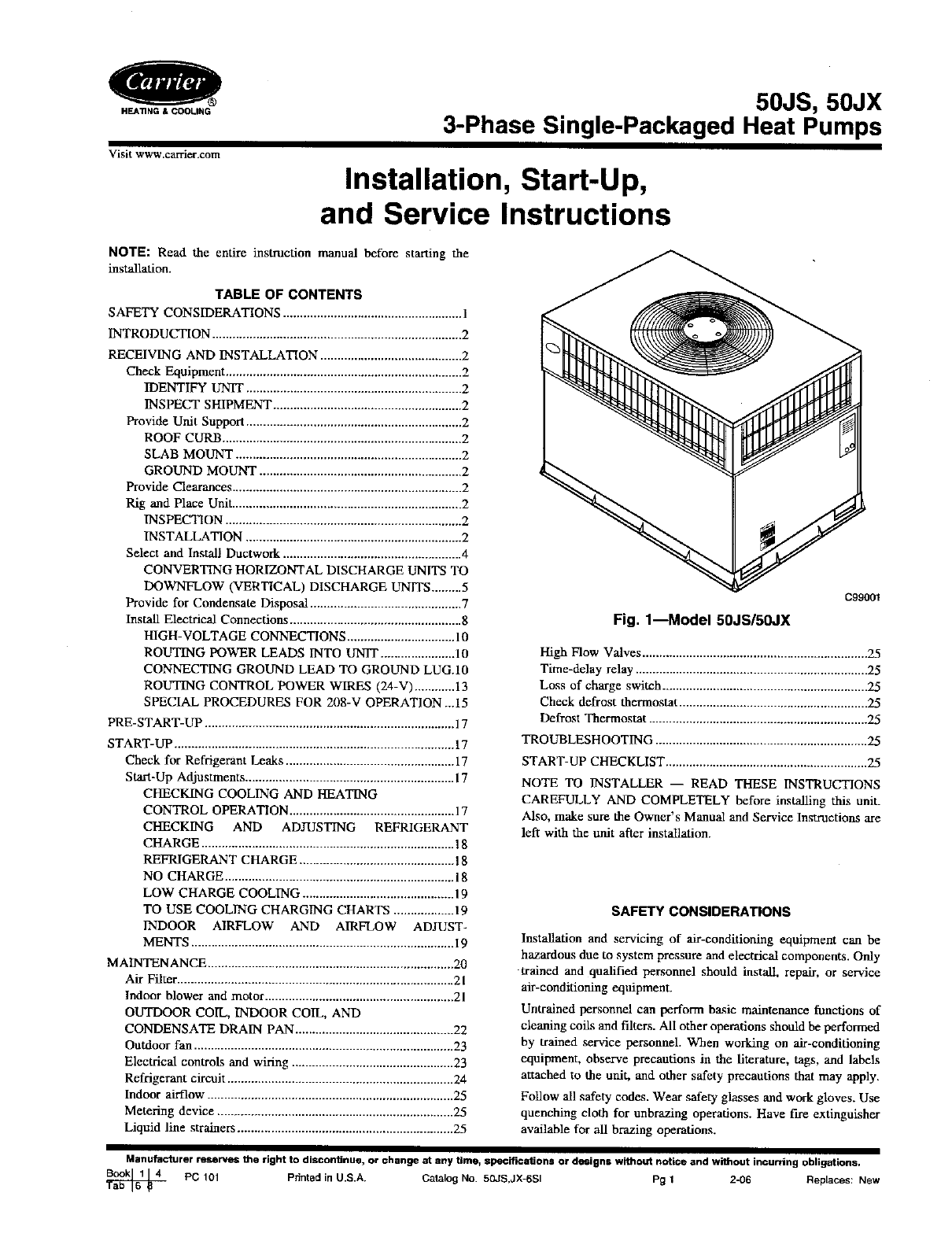
C99001
Fig. 1--Model 50JS/50JX
High Flow Valves ................................................................... 25
Time-delay relay ..................................................................... 25
Loss of charge switch ............................................................. 25
Check defrost thermostat ........................................................ 25
Defrost Thermostat ................................................................. 25
TROUBLESHOOTING ............................................................... 25
START-UP CHECKLIST ............................................................ 25
NOTE TO INSTALLER -- READ THESE INSTRUCTIONS
CAREFULLY AND COMPLETELY before installing this unit.
Also, make sure the Owner's Manual and Service Instructions are
left with the unit after installation.
SAFETY CONSIDERATIONS
Installation and servicing of air-conditioning equipmem can be
hazardous due to system pressure and electrical components. Only
trained and qualified personnel should install, repair, or service
air-conditioning equipment.
Untrained personnel can perform ba._ic maintenance functions of
cleaning coils and filters. All other operations should be performed
by trained service personnel. When working on air-conditioning
equipment, observe precautions in the literature, tags, and labels
attached to the unit, and other safety precautions that may apply.
Follow all safety codes. Wear safety glasses and work gloves. Use
quenching cloth for unbrazing operations. Have fire extinguisher
available for all brazing operations.
Manufacturer reserves the right to discontinue, or change at any time, specifications or designs without notice and without incurring obligations,
PC 101 Printed in U.S.A. Catalog No. 50JS,JX-6SI Pg 1 2-06 New
Replaces:
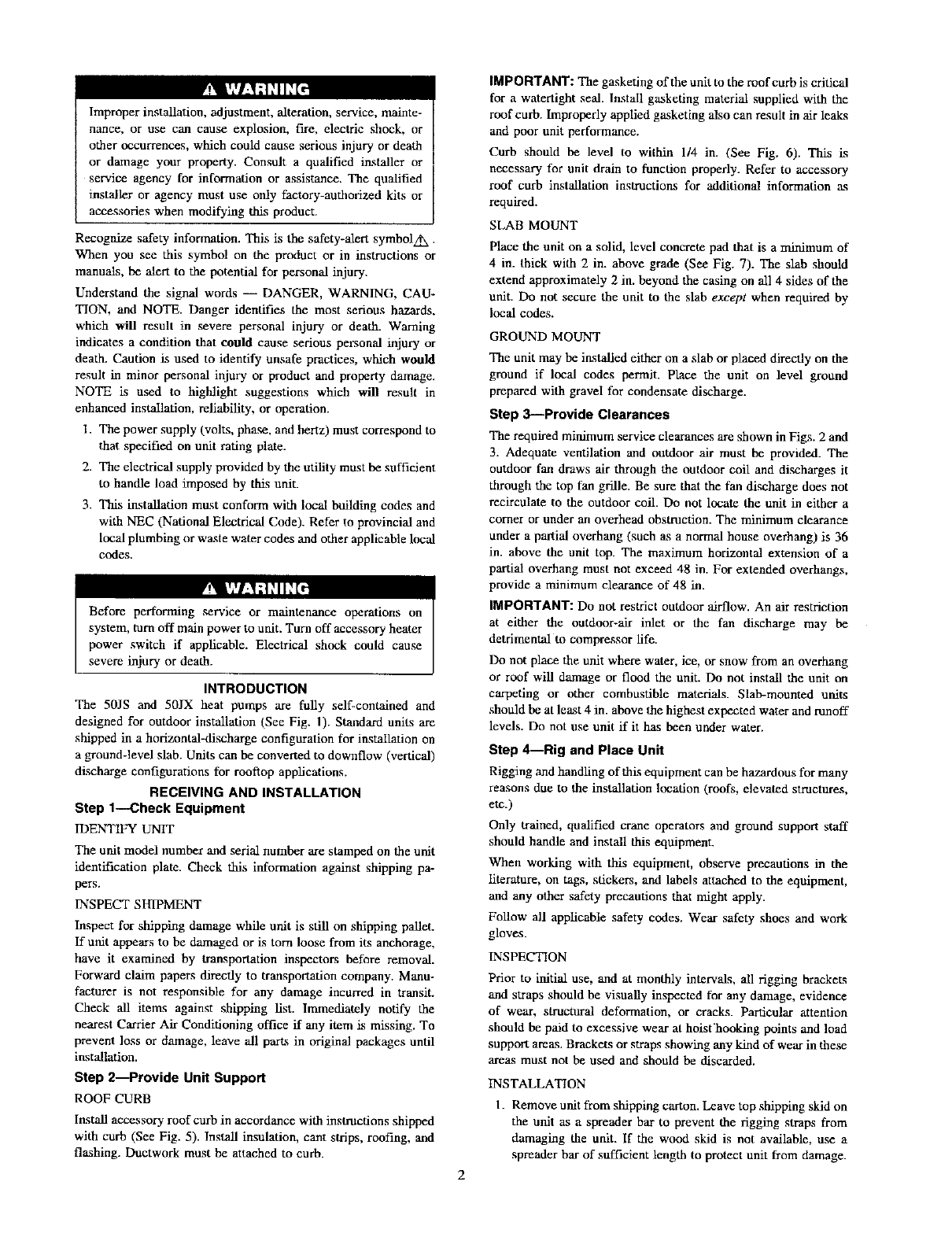
Improper installation, adjustment, alteration, service, mainte-
nance, or use can cause explosion, fire, electric shock, or
other occurrences, which could cause serious injury or death
or damage your property. Consult a qualified installer or
service agency for information or assistance. The qualified
installer or agency must use only factory-authorized kits or
accessories when modifying this product.
Recognize safety information. This is the safety-aler_ symbolAx.
When you see this symbol on the product or in instructions or
manuals, be alert to the potential for personal injury.
Understand the signal words -- DANGER, WARNING, CAU-
TION, and NOTE. Danger identifies the most serious hazards,
which will result in severe personal injury or death. Warning
indicates a condition that could cause serious personal injury or
death. Caution is used to identify unsafe practices, which would
result in minor personal injury or product and property damage.
NOTE is used to highlight suggestions which will result in
enhanced installation, reliability, or operation.
1. The power supply (volts, phase, and hertz) must correspond to
that specified on unit rating plate.
2. The electrical supply provided by die utility must be sufficient
to handle load imposed by this unit.
3. This installation must confurm with local building codes and
with NEC (National Electrical Code). Refer to provincial and
local plumbing or waste water codes and other applicable local
codes.
severe inJUry or death.
INTRODUCTION
The 50JS and 50JX heat pumps are fully self-contained and
designed for outdoor installation (See Fig. 1). Standard units are
shipped in a horizontal-discharge configuration for installation on
a ground-level slab, Units can be converted to downflow (vertical)
discharge configurations for rooftop applications.
RECEIVING AND INSTALLATION
Step 1--Check Equipment
IDENTIFY UNIT
The unit model number and serial number are stamped on the unit
identification plate. Check this information against shipping pa-
pers.
INSPECT SHIPMENT
Inspect for shipping damage while unit is still on shipping pallet.
If ualt appears to be damaged or is torn loose from its anchorage,
have it examined by transportation inspectors before removal.
Forward claim papers directly to transportation company. Manu-
facturer is not responsible for any damage incurred in transit.
Check all items against shipping list. Immediately notify the
nearest Carder Air Conditioning office if any item is missing. To
prevent loss or damage, leave all parts in original packages until
installation.
Step 2--Provide Unit Support
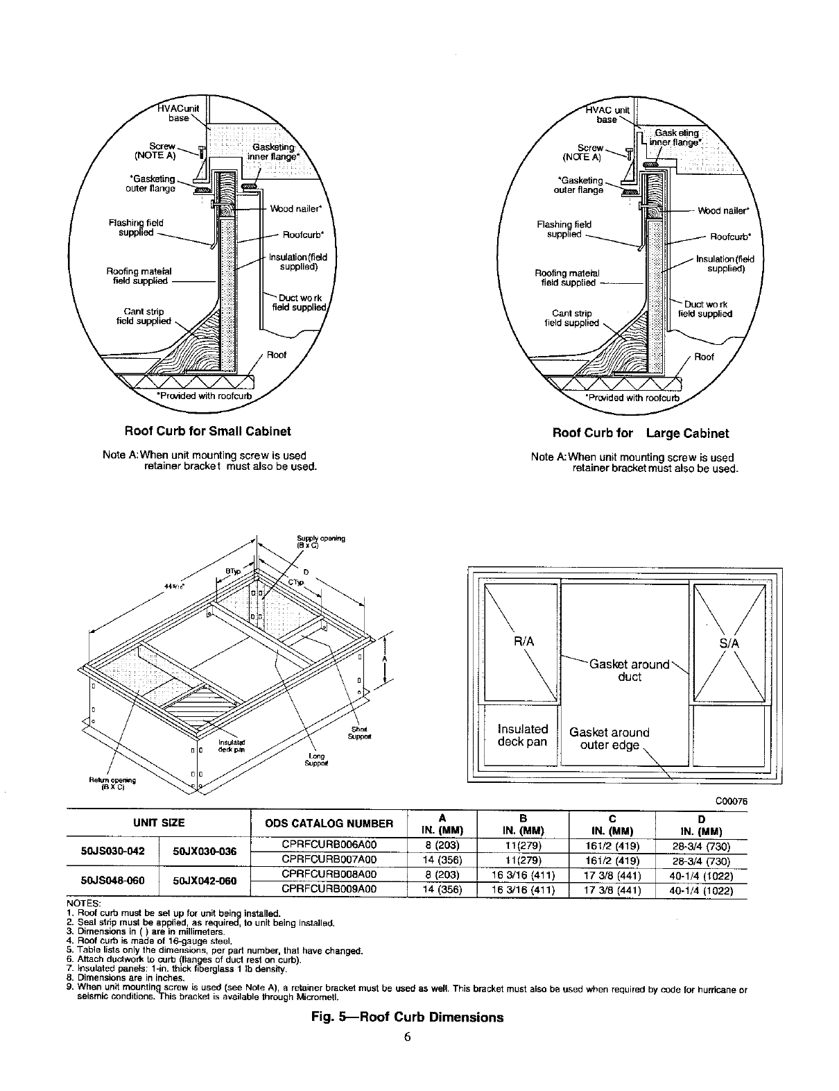
ROOF CURB
Install accessory roof curb in accordance with instructions shipped
with curb (See Fig. 5). Install insulation, cant strips, roofing, and
flashing. Ductwork must be attached to curb.
2
IMPORTANT: The gasketing of the unit to the roof curb is critical
for a watertight seal. Install gaskeling material supplied with the
roof curb. Improperly applied gasketing also can result in air leaks
and poor unit performance.
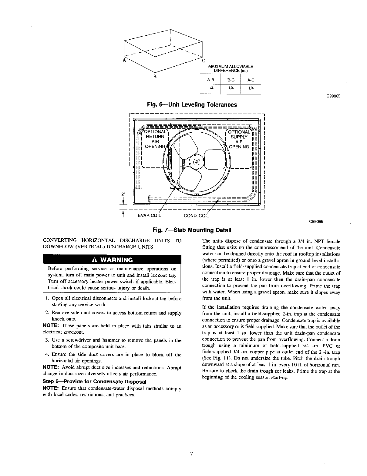
Curb should be level to within 1/4 in. (See Fig. 6). This is
necessary for unit drain to function properly. Refer to accessory
roof curb installation instructions for additional information a-s
required.
SLAB MOUNT
Place the unit on a solid, level concrete pad that is a minimum of
4 in. thick with 2 in. above grade (See Fig. 7). The slab should
extend approximately 2 in. beyond the casing on all 4 sides of the
unit. Do not secure the unit to the slab except when required by
local codes.
GROUND MOUNT
The unit may be installed either on a slab or placed directly on the
ground if local codes permit. Place the unit on level ground
prepared with gravel for condensate discharge.
Step 3---Provide Clearances
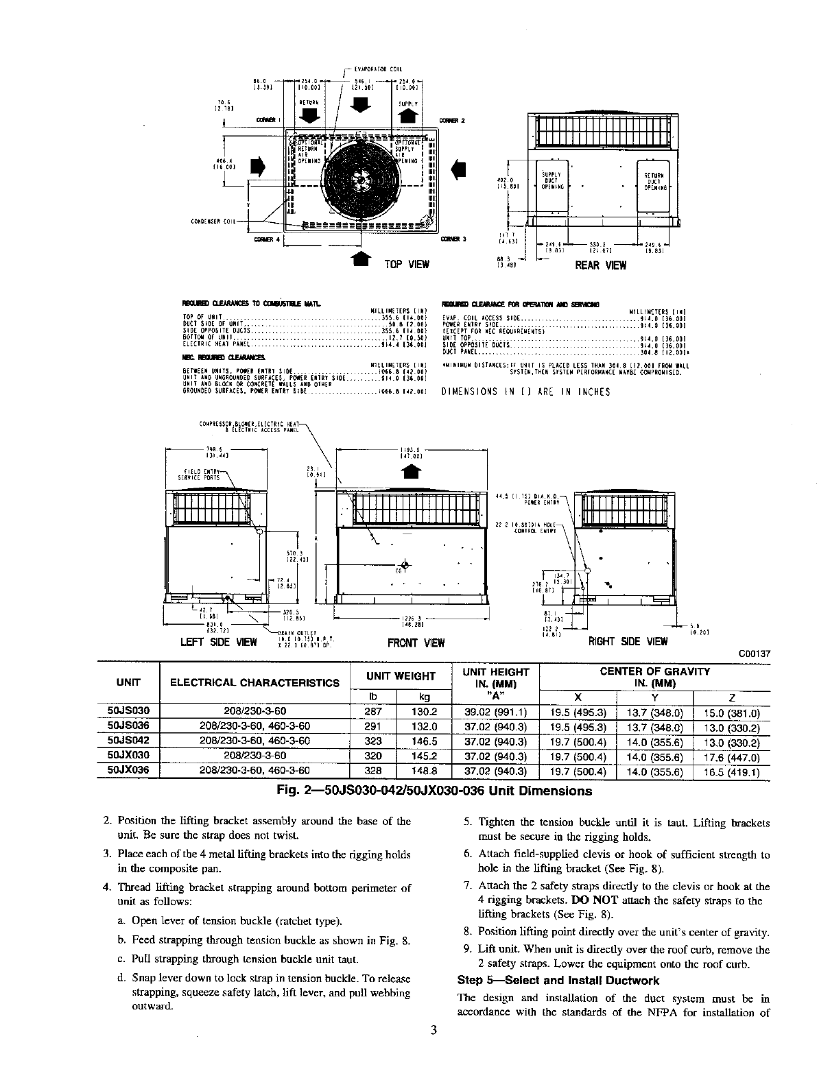
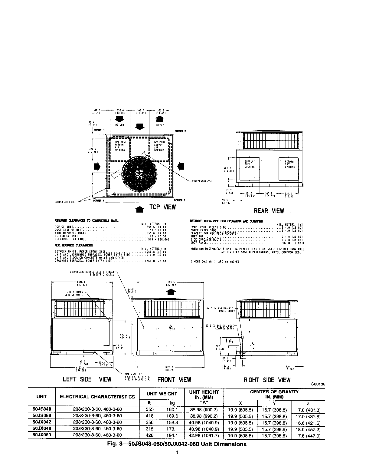
The required minimum service clearances are shown in Figs. 2 and
3. Adequate ventilation and ouUloor air must be provided. The
outdoor fan draws air through the outdoor coil and discharges it
through the top fan grille. Be sure that the fan discharge does not
recirculate to the outdoor coil. Do not locate the unit in either a
corner or under an overhead obstruction. The minimum clearance
under a partial overhang (such as a normal house overhang) is 36
in. above the unit top. The maximum horizontal extension of a
partial overhang must not exceed 48 in. For extended overhangs,
provide a minimum clearance of 48 in.
IMPORTANT: Do not restrict outdoor airflow. An air restriction
at either the outdoor-air inlet or die fan discharge may be
detrimental to compressor life.
Do not place the unit where water, ice, or snow from an overhang
or roof will damage or flood the unit. Do not install the unit on
carpeting or other combustible materials. Slab-mounted units
should be at least 4 in. above the highest expected water and runoff
levels. Do not use unit if it has been under water.
Step 4--Rig and Place Unit
Rigging and handling of this equipment can be hazardous for many
reasons due to the installation location (roofs, elevated structures,
etc.)
Only trained, qualified crane operators and ground support staff
should handle and install this equipment.
When working with this equipment, observe precautions in the
literature, on tags, stickers, and labels attached to the equipment,
and any other safety precautions that might apply.
Follow all applicable safety codes. Wear safety shoes and work
gloves.
INSPECTION
Prior to initial use, and at monthly intervals, all rigging brackets
and straps should be visually inspected for any damage, evidence
of wear, structural deformation, or cracks, particular attention
should be paid to excessive wear at hoist hooking points and load
support areas. Brackets or straps showing any kind of wear in these
areas must not be used and should be discarded.
INSTALLATION
1. Remove unit from shipping carton. Leave top shipping skid on
the unit as a spreader bar to prevent the rigging straps from
damaging the unit. If the wood skid is not available, use a
spreader bar of sufficient length to protect unit from damage.
/_[V_P0eAT0e C01t
I
t TOP VIEW
_lllllllllllllllllll_
HIIIIIIIIIIIII!lllml_
iUPPL_
_O? _UCT DL_T
[_5 8_1 OPEW_WG, , . OpEwiWG
t3 ,s_ REAR VIEW
FEG_J_) a_-iilLll/iC_S Ti_ C{Ji_'I]HUE W._'ia- _ _ ROR _l_fl /€_ _
WILLIWETER$ {IN) MILLtM[TER_ { INI
FOP OF UNIT ................................... 355¸6 {14.00} [VAp COIL ACC[$$ $1D[ ..................... 9_4.0 [3_ 001
DU¢1 S_O[ OF UNIT ............................. 50 8 [2 00} P_[_ [HIR_ $rD[ .......................... 9_4 0 [3_ 001
_ID[ OPPOSIT[ OUCTS............................ _55.6 (1_ 00} ([ICEPT FOR HEC R[OUIREWEWTS}
BOTTOll OF _iHI1 ............................... 121 {0.50) uHrT TOp ............................. 914.0 [3_ 001
ELECTRIC H_AT PANEL .......................... _14 4 [3_ 001 SID[ OPPO_IT[ DLiCIS ...................... _;4.0 {3_.001
_U_T PAN[L .......................................... 304¸8 [1_.00]_
M_., U CLF.AdUdiC_ W_LLIW[T[RS [IN] ,_IHIHUW DISTAHC[S:_F _HIT IS PLACID LESS THAH _Od8 [1_ 0_1 FR{_,dWALL
BETWEEH UNITS, POI[R [#TRf SI{)[ ....................... _065 8[_ 00) $_STEW,TH[N S_ST[W PERFORWAHC[ WkYBE ¢_PROWIS[D.
UHIT kWD UN_ROUNO[_ SURF_C[$, pO,ie[R [NIRY SlOE .... 91_ 0 {35 00]
UWIT _WD BLOCK Oe _Oe_:R[TE WALL_ AHD OI_ER
GROUNDEDSURFAC_S, POi[R[RTR_51D[ .............. _066.814_.00] DIMENSIONS [N [] ARE IN INCHES
UNIT
50JS03O
50JS036
50JS042
50JXO30
50JX036
t
. • , , .
Iit
FRONT VIEW
,I,Ll l!llllll
IL_3]_
RIGHT SIDE VIEW
ELECTRICAL CHARACTERISTICS
208/230-3-60
208/230-3-60, 460-3-60
208/230-3-60, 460-3-60
263/230-3-60
208/230-3-60, 460-3-66
UNIT WEIGHT UNiT HEIGHT
IN. (MM)
Ib kg "A"
287 130.2 39.02 (991.1)
291 132.0 37.02 (940.3)
323 146.5 37.02 (940.3)
320 145.2 37.02 (940.3)
328 148.8 37.02 (940.3)
X
19.5 (495.3)
19.5 (495.3)
19.7 (500.4)
19,7 (500.4)
19.7 (500.4)
Fig. 2--50JS030-O42/50JX030-036 Unit Dimensions
CENTER OF GRAVITY
IN.(MM)
Y
13,7 (348.0)
13.7 (348.0)
14.0 (355.6)
14.0 (355.6)
14.0 (355.6)
C00137
Z
15.0 (381.o)
13,0(330.2)
13.0 (330.2)
17.6 (447.0)
16.5 (419.1)
2. Position the lifting bracket assembly around the ba._e of the
unit. Be sure the strap does not twist.
3. Place each of the 4 metal tiffing brackets into the rigging holds
in the composite pan.
4. Thread lifting bracket strapping around bottom perimeter of
unit as follows:
a. Open lever of tension buckle (ratchet type).
b. Feed strapping through tension buckle as shown in Fig. 8.
c. Pull strapping through tension buckle unit taut.
d. Snap lever down to lock strap in tension buckle. To release
strapping, squeeze safety latch, lift lever, and pull webbing
outward.
5. Tighten the tension buckle until it is taut. Lifting brackets
must be secure in the rigging holds.
6. Attach field-supptied clevis or hook of sufficient strength to
hole in the tiffing bracket (See Fig. 8).
7. Attach the 2 safety strops directly to the clevis or hook at the
4 rigging brackets. DO NOT attach the safety straps to the
tiffing brackets (See Fig. 8).
8. Position lifting point directly over the unit's center of gravity.
9. Lift unit. When unit is directly over the roof curb, remove the
2 safety straps. Lower the equipment onto the roof curb.
Step S--Select and Install Ductwork
The design and installation of the duct system must be in
accordance with the standards of the NFPA for installation of
/TOP VIEW
FdmLIFS) CLF.ARANC_$ TO _IM_TL
MELLIM[T[RS [[g]
TOP OF UNIT ........................................ 35S.6 [14 00]
DUCT $1D[ OF UNIT ................................... S08 [Z 00]
SIO_ OPPOSIIE DUCTS ......................... 355 6 [14 00]
80TIll Or I_ 7• [0 S01
ELECTRIC _[k7 PkNEL ........................ 914¸4 (3_C0]
MEC. REGUFa) C_JOUNCEI
MILLIMETERS {IK]
BETWE[N UNITS, POM[R [RTR? SII)[ ................ J066.8 [42 00]
Ugll kND IINGROUND[D SUBFkC[S. POiER [NTRy SJ[JE ........ 914.0 [3G 01_]
UNII kND BL_ OR CO_RETE WkLLS kND OTN[R
61tOUNOED $UItFkC[S. pOW[It ENTRY SI_[ ............... 10668 [_2 00]
JllllllllJllllllll
lll!lllllllllllllII
_UPPL_ " , . NETUNN
402 rm[NlUG
[15 _3]
I I I
--34_3 _
REAR VIEW
FIEaLIR_D _FOR _'noN _
MILLIMETERS {IN]
EVAP. COIL ACC[S$ SlOE ............................ 9140 [36001
POiE_ [NTEY SID[ ................................. 914_ [360_}
I[X_PI FOR gEC REOUIR[_[NTS}
SI_E OPFOSIT£ DUCIS ................. 914¸0 [3600]
_ll_T pkNEL ....................... 304¸8 [1_00]*
IMIRIMUW DISIANC[_IF UNI[ I_ PLAC[O LESS fNkN 304 8 [12 00] FBO_ WALL
SY$1EM.IN[N $_$T[N p[R_OENkNC[ N_O[ _OgPgOMIS[O.
DIM[NSIONS IN [] A_E IW INC_[S
UNIT
5_S_8
5_S_0
5_X_2
5_X_8
5_X_0
ittttttft ttl t,
tttttttlt{ttt{l.
=i=, _' i_--_ =_
lilt I _ii_,
LEFT SIDE
[41 00)
/
i ililllllliillllltti
,!llllll!l, llllltlill
'_"i" .i'
VIEW ,_ ........... FRONT VIEW
PONE_E_IN_
184 6
[4 81]
Jllllltllllllllllh
IIjIIIIIIIIII IlU
•
5o
RIGHT SIDE VIEW
ELECTRICAL CHARACTERISTICS
208/230-3-60, 460-3-60
208/230-3-60, 460-3-60
208/230-3-60, 460-3-60
208/230-3-60, 468-3-60
208/230-3-60,460-3-60
UNIT WEIGHT UNIT HEIGHT
IN. (MM)
Ib kg "A"
353 160.1 38.96 (990.2)
418 189.6 38.98 (990.2)
350 158.8 40.98 (1040.9)
315 170.1 40.98 (1040.9)
428 194.1 42.98 (1091.7)
X
19.9 (505.5)
19.9 (505,5)
19.9 (505.6)
19.9 (505.5)
19.9 (505.5)
CEWrER OF GRAVITY
IN. (MM)
Y
15.7 (398.8)
15.7 (398.8)
15.7 (398.8)
15.7 (398.8)
15.7 (398.6)
C00136
z
17.0 (431.8)
17.0 (431.8)
16.6 (421.6)
18.0 (457.2)
17.6 (447,0)
Fig. 3---50JS048-060/50JX042-060 Unit Dimensions
4
12
Y
O)
o
tt_
o
O
4X3
CORNER WEIGHTS (SMALL CABINET)
Unit 30 36 42
Total Weight 287 291 323
Corner Weight 1 66 67 83
Corner Weight 254 55 55
Corner Weight 3 62 63 78
Corner Weight 4 105 106 107
o
0
CORNER WEIGHTS (LARGE CABINET)
Unit 48 60
Total Weight 353 418
Corner Weight 1 76 90
Corner Weight 2 49 58
Corner Weight 3 96 114
Corner Weight 4 132 156
G00071
x
U3
13
0
CORNER WEIGHTS (SMALL CABINET)
Unit 30 36 --
Total Weight 320 328 --
Corner Weight 1 63 64 --
Corner Weight 2 74 76 --
Corner Weight 356 58 --
Corner Weight 4 127 130 --
X
o
o
-- "D
o
CORNER WEIGHTS (LARGE CABINET)
Unit 42 48 60
Total Weight 350 375 428
Corner Weight 1 75 81 92
Corner Weight 2 49 52 60
Corner Weight 3 95 102 116
Corner Weight 4 131 140 160
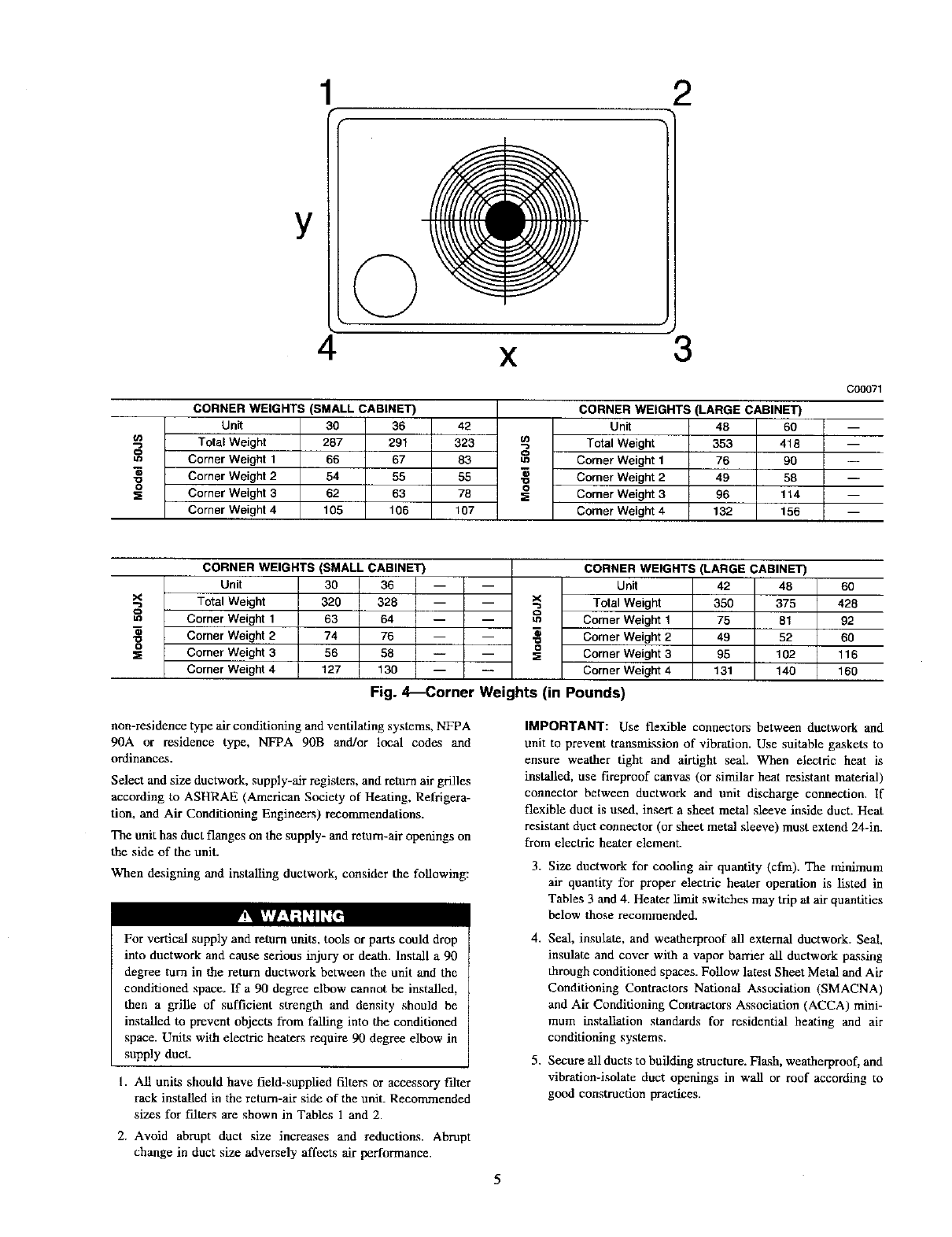
Fig. 4_Corner Weights (in Pounds)
non-residence type air conditioning and ventilating systems, NFPA
90A or residence type, NFPA 90B and/or local codes and
ordinances.
Select and size ductwork, supply-air registers, and return air grilles
according to ASHRAE (American Society of Heating, Refrigera-
tion, and Air Conditioning Engineers) recommendations.
The unit has duct flanges on the supply- and return-air openings on
the side of the unit.
When designing and installing ductwork, consider die following:
For vertical supply and return units, tools or parts could drop
into ductwork and cause serious injury or death. Install a 90
degree turn in the return ductwork between the unit and the
conditioned space. If a 90 degree elbow cannot be installed,
then a grille of sufficient strength and density should be
installed to prevent objects from falling into the conditioned
space. Units with electric heaters require 90 degree elbow in
supply duct.
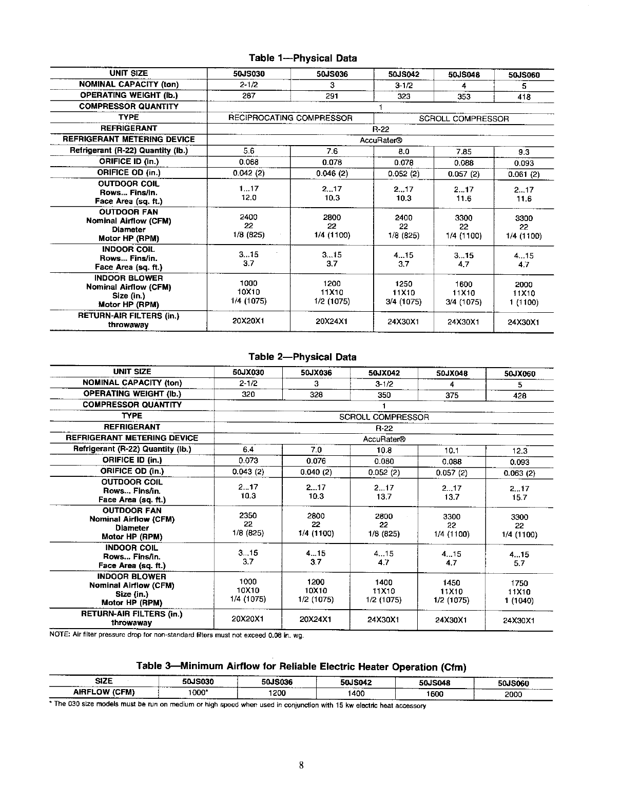
I. All units should have field-supplied filters or accessory falter
rack installed in the return-air side of the unit. Recommended
sizes for filters are shown in Tables 1 and 2.
2. Avoid abrupt duct size increases and reductions. Abrupt
change in duct size adversely affects air performance.
IMPORTANT: Use flexible connectors between ductwork and
unit to prevent transmission of vibration. Use suitable gaskets to
ensure weather tight and airtight seal. When electric heat is
installed, use fireproof canvas (or similar heat resistant material)
connector between ductwork and unit discharge connection. If
flexible duct is used, insert a sheet metal sleeve inside duct. Heat
resistant duct connector (or sheet metal sleeve) must extend 24-in.
from electric heater element.
3. Size ductwork for cooling air quantity (cfm). The minimum
air quantity for proper electric heater operation is listed in
Tables 3 and 4. Heater limit switches may trip at air quantities
below those recommended.
4. Seal, insulate, and weatherproof all external ductwork. Seal,
insulate and cover with a vapor barrier all ductwork passing
through conditioned spaces. Follow latest Sheet Metal and Air
Conditioning Contractors National Association (SMACNA)
and Air Conditioning Contractors Association (ACCA) mini-
mum installation standards for residential hearing and air
conditioning systems.
5. Secure all ducts to building structure. Flash, weatherproof, and
vibration-isolate duct openings in wall or roof according to
good construction practices.
5
VACunit
/ou .a.
Wood nailer*
Rashing field •
I_:11 _¢ Insulation(field
field supplied -- --
Duct work
Cant strip field supplied
field supplied
Roof Curb for Small Cabinet
Note A:When unit mounting screw is used
retainer bracket must also be used.
Roof Curb for Large Cabinet
Note A:When unit mounting screw is used
retainer bracket must also be used.
SUpp opening
IBx_
Returnopemng
(exc)
UNIT SIZE
50JS030-042 50JX030-036
50JS048-060 50JX042-060
Long
\R/A
\
Insulated
deck pan
_-Gasket around
duct
Gasket around
outer edge _
\/
S/A
/\
ODS CATALOG NUMBER
CPRFCURBO06AO0
CPRFCURBOO7AO0
CPRFCURB008AO0
CPRFCURB069A00
NOTES:
1. Roof curb must be set up for unit being installed.
2. Seal strip must be applied, as required, to unit being installed.
3. Dimensions in ( ) are in millimeters.
4. Roof curb is made of 16-gauge steel.
5. Table lists only the dimensions, per pad number, that have changed.
6. Attach ductworb to curb (flanges of duct rest on curb).
7. Insulated panels: 1-in. thick fiberglass 1Ib density.
8. Dimensions are in inches.
A
IN.(MM)
6(203)
14 (356)
8 (203)
14 (356)
C00076
BCD
IN. (MM) IN. (MM) IN. (MM)
11(279) 151/2 (419) 28-3/4 (730)
11(279) 161/2 (419) 28-3/4 (730)
16 3/16 (411) 17 3/8 (441) 40-1/4 (1022)
16 3/16 (411) 17 3/8 (441) 40-1/4 (1022)
9. When unit mounting screw is used (see Note A), a retainer bracket must be used as well. This bracket must also be used when required by code for hurricane or
seismic conditions. This bracket is available through Micrometl.
Fig. 5_Roof Curb Dimensions
6
B
MAXIMUM ALLOWABLE
DIFFERENCE(in.)
A-B A-c
1/4 1'4
Fig. 6--Unit Leveling Tolerances
C99065
EVAR COIL COND. COrL
C99096
Fig. 7--Slab Mounting Detail
CONVERTING HORIZONTAL DISCHARGE UNITS TO
DOWNFLOW (VERTICAL) DISCHARGE UNITS
M_
Before performing service or maintenance operations on
system, turn off main power to unit and install lockout tag.
Turn off accessory heater power switch if applicable. Elec-
trical shock could cause serious injury or death.
1. Open all electrical disconnects and install lockout tag before
starting any service work.
2. Remove side duct covers to access bottom return and supply
knock outs.
NOTE: These panels are held in place with tabs similar to an
electrical knockout.
3. U_ a ,screwdriver and hammer to remove the panels in the
bottom of the composite unit base.
4. Ensure the side duct covers are in place to block off the
horizontal air openings.
NOTE: Avoid abrupt duct size increases and reductions. Abrupt
change in duct size adversely affects air performance.
Step 6--Provide for Condensate Disposal
NOTE: Ensure that condensate-water disposal methods comply
with local codes, restrictions, and practices.
The units dispose of condensate through a 3/4 in. NPT female
fitting that exits on the compressor end of the unit. Condensate
water can be drained directly onto the roof in rooftop installations
(where permitted) or onto a gravel apron in ground level installa-
tions. Install a field-supplied condensate trap at end of condensate
connection to ensure proper drainage. Make sure that the outlet of
the trap is at lea_st 1 in. lower than the drain-pan condensate
connection to prevent the pan from overflowing. Prime the trap
with water. When using a gravel apron, make sure it slopes away
from the unit.
If the installation requires draining the condensate water away
from the unit, install afield-supplied 2-in. trap at the condensate
connection to ensure proper drainage. Condensate trap is available
as an accessory or is field-supplied. Make sure that the outlet of the
trap is at learnt I in. lower than the unit drain-pan condensate
connection to prevent the pan from overflowing. Connect a drain
trough using a minimum of field-supplied 3/4 -in. PVC or
field-supplied 3/4 -in. copper pipe at outlet end of the 2 -in. trap
(See Fig. 11). Do not undersize the tube. Pitch the drain trough
downward at aslope of at least 1 in. every l0 ft. of horizontal run.
Be sure to check the drain trough for leaks. Prime the trap at the
beginning of the cooling season start-up.
7
UNIT SIZE
NOMINAL CAPACITY (ton)
OPERATING WEIGHT (lb.)
COMPRESSOR QUANTITY
TYPE
REFRIGERANT
REFRIGERANT METERING DEVICE
Refrigerant (R-22) Quantity (lb.)
ORIFICE ID (in.)
ORIFICE OD (in.)
OUTDOOR COIL
Rows... Fins/in.
Face Area (sq, ft.)
OUTDOOR FAN
Nominal Airflow (CFM)
Diameter
Motor HP (RPM)
INDOOR COIL
Rows... Fins/in.
Face Area (sq. ft,)
INDOOR BLOWER
Nominal Airflow (CFM)
Size (in.)
Motor HP (RPM)
RETURN-AIR FILTERS (in.)
throwaway
Table 1--Physical Data
50JS03O 50JS036
2-1/2 3
287 291
RECIPROCATING COMPRESSOR
50JS042 50JS048 5OJS060
4 5
353 418
SCROLL COMPRESSOR
3-1/2
323
1
R-22
AccuRater_
8.0
0.078
0.052 (2)
2.,.17
10.3
2400
22
1/8 (825)
4...15
3.7
1250
11X10
3/4 (1075)
7,85 9.3
0.088 0.093
0.057 (2) 0.061 (2)
2...17 2...17
11.6 11.6
3300 3300
22 22
1/4 (1100) 1/4 (1100)
3...18 4,..15
4.7 4.7
1600 2000
11XI0 11X10
3/4 (1075) 1 (1100)
24X30X1 24X30X1
5.6 7.6
0.068 0.078
0.042 (2) 0.046 (2)
1...17 2,,.17
12.0 10.3
2400 2800
22 22
1/8 (825) 1/4 (1100)
3-.15 3...15
3.7 3.7
1000 1200
10X10 11X10
1/4 (1075) 1/2 (1075)
20X20X1 20X24X1 24X30X1
UNIT SIZE
NOMINAL CAPACITY (ton)
OPERATING WEIGHT (lb.)
COMPRESSOR QUANTITY
TYPE
REFRIGERANT
REFRIGERANT METERING DEVICE
Refrigerant (R-22) Quantity (lb.)
ORIFICE ID (in.)
ORIFICE OD (in.)
OUTDOOR COIL
Rows... Fins/in.
Face Area (sq, ft,)
OUTDOOR FAN
Nominal Airflow (CFM)
Diameter
Motor HP (RPM)
INDOOR COIL
Rows... Fins/in.
Face Area (sq. ft.)
INDOOR BLOWER
Nominal Airflow (CFM)
Size (in.)
Motor HP (RPM)
RETURN-AIR FILTERS (in.)
throwaway
Table 2--Physical Data
50JX030
2-1/2
32O
6.4
0.073
0.043 (2)
2...17
10.3
2350
22
1/8(825)
3...15
3.7
50JX036 50JX042
3 3-1/2
328 350
1
SCROLL COMPRESSOR
R-22
AccuRater_
7.0 10.8
0.076 0.080
0.040 (2) 0.052 (2)
2...17 2...17
10.3 13.7
2800 2800
22 22
114 (1100) 1/8 (825)
4...15 4...15
3.7 4.7
1200 1400
10X10 11X10
1/2 (1075) 1/2 (1075)
20X24X1 24X30X1
50JX048
4
375
10.1
0.088
01057 (2)
2...17
13.7
3300
22
1_ (1100)
4._15
4.7
50JX060
5
428
12.3
0.093
0.063 (2)
2..,17
15.7
3300
22
1/4 (1100)
4...15
5.7
1000 1450 1750
10X10 11X10 11X10
1/4 (1075) 1/2 (1075) 1(1040)
20X20X1 24X30Xl 24X30X1
NOTE;Air filter pressuredropfor non-standardfiriersmustnotexceed 0.08 in. wg.
Table 3_Minimum Airflow for Reliable Electric Heater Operation (Cfm)
SIZE 50JS030 50JS036 50JS042 50JS048 50JS06O
AIRFLOW (CFM) 1000" 1200 1400 1600 2000
* The 030 siZemodels mustbe runon mediumor highspeedwhen usedinconiunctionwith 15 kwelectric heataccessory
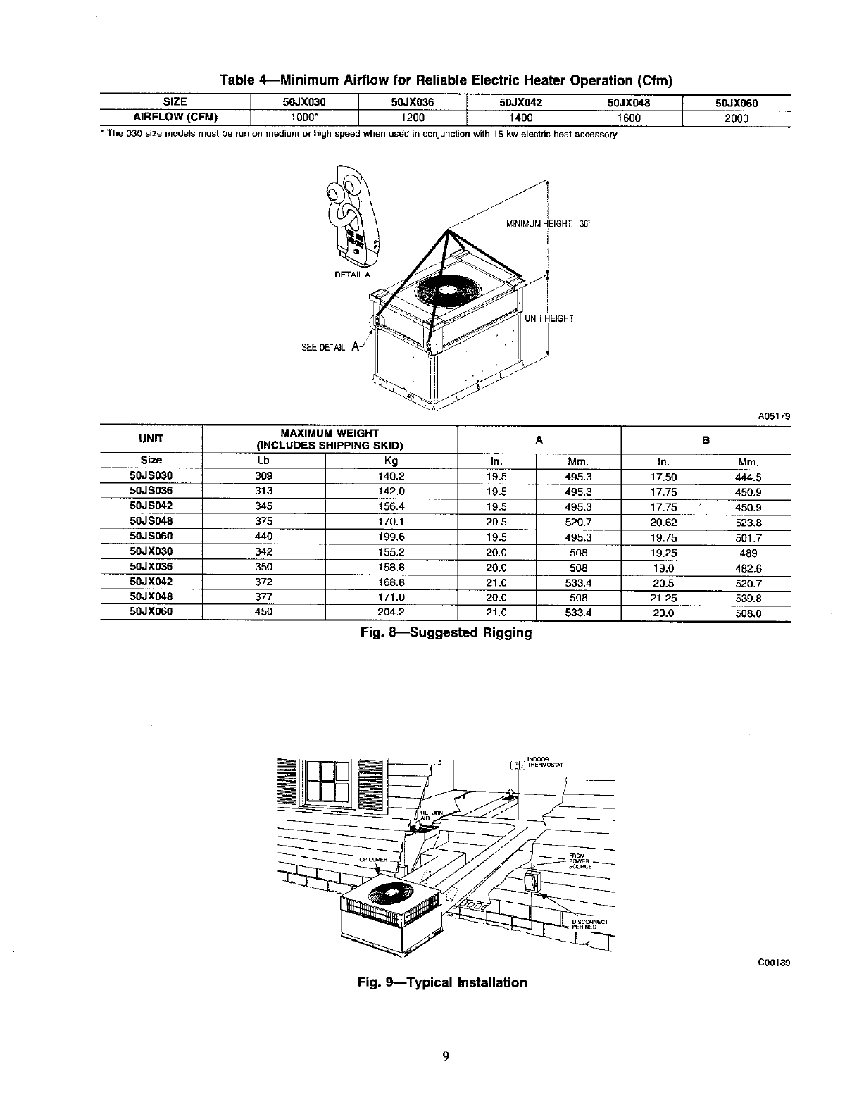
Table 4---Minimum Airflow for Reliable Electric Heater Operation (Cfm)
SIZE 50JX03O 50JX036 50JX042 50JX048
AIR FLOW (C FM) 13O0" 1200 1400 1600
• The 030 size models mustbe runon mediumorhighspeedwhenusedin conjunctionwith 15 kwelectricheataccessory
50JX060
2000
DETAIL A
(
SEEDETAILA_'
UNIT
Size
50JS030
50JS036
50JS042
50JS048
50JS060
50JXO30
50JX036
50JX042
50JX048
50JX060
MAXIMUM WEIGHT
(INCLUDES SHIPPING SKID)
Lb
3O9
313
345
375
440
342
350
372
377
45O
Kg
140.2
142,0
156.4
170.1
199.6
155.2
159.8
168.8
171.0
204.2
Fig. &--Suggested
A
In.
19.5
19.5
19.5
20.5
19.5
20.0
20.0
21.O
20.0
21.0
Rigging
B
Mm. In.
495.3 17,50
495.3 17.75
495.3 17.75
520.7 20.62
495.3 19.75
508 19,25
508 19.0
533.4 20.5
508 21.25
533.4 20.0
A05179
in3.
444.5
450.9
450.9
523.8
501.7
489
482.6
520.7
539.8
508,0
Fig. 9_Typical Installation
C00139
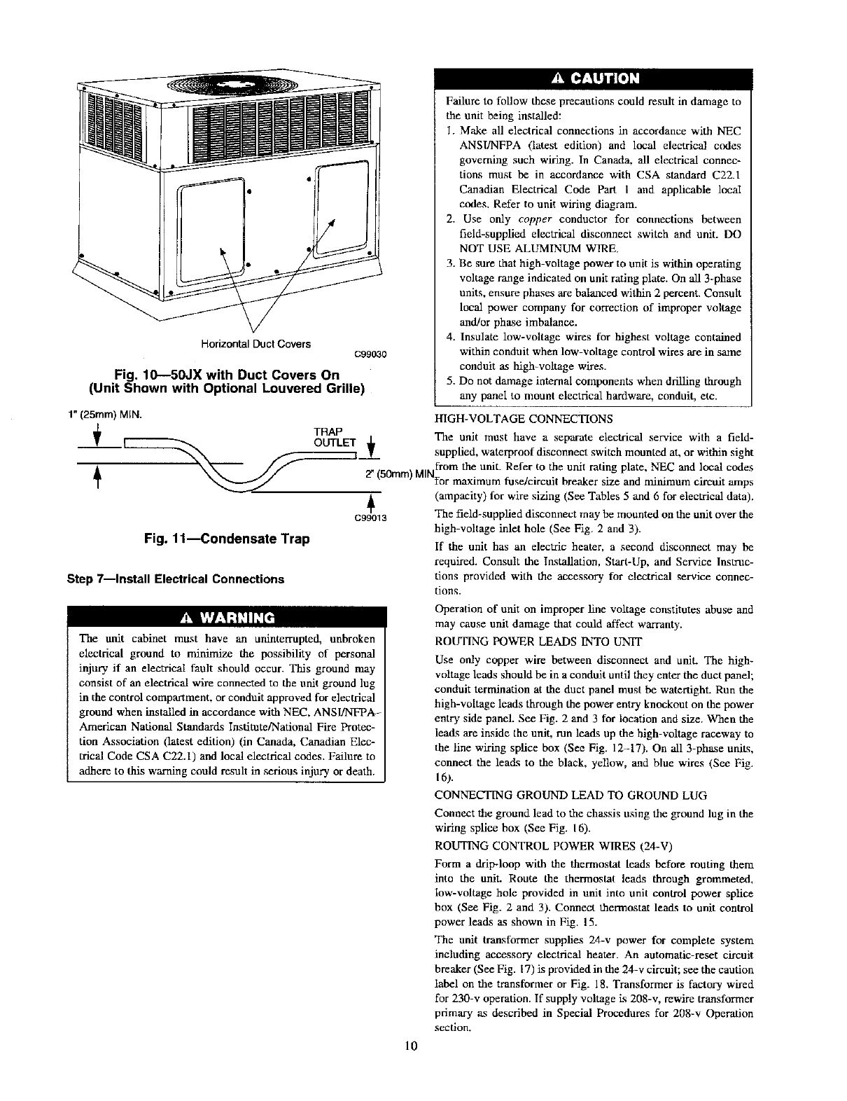
Horizontal Duct Covers c99030
Fig. 10--50JX with Duct Covers On
(Unit Shown with Optional Louvered Grille)
Failure to follow these precautions could result in damage to
the unit being installed:
1. Make all electrical connections in accordance with NEC
ANSI/NFPA (latest edition) and local electrical codes
governing such wiring. In Canada, all electrical connec-
tions must be in accordance with CSA standard C22.1
Canadian Electrical Code Part I and applicable local
codes. Refer to unit wiring diagram.
2. Use only copper conductor for connections between
field-supplied electrical disconnect switch mad unit. DO
NOT USE ALUMINUM WIRE.
3. Be sure that high-voltage power to unit is within operating
voltage range indicated on unit rating plate. On all 3-phase
units, ensure phases are balanced within 2 percent. Consult
local power company for correction of improper voltage
and/or phase imbalance.
4. Insulate low-voltage wires for lfighest voltage contained
within conduit when low-voltage control wires are in same
conduit as high-voltage wires.
5. Do not damage internal components when drilling through
any panel to mount electrical hardware, conduit, etc.
1" (25ram) MIN.
+
+
HIGH-VOLTAGE CONNECTIONS
TRAP
OUTLET _ The unit must have a separate electrical service with a field-
_F'_ --""""7 T supplied, waterproof disconnect switch mounted at, or within sight
from the unit. Refer to the unit rating plate, NEC and local codes
2" 50mm) MIN .
]-or maximum fuse/c rcu breaker size and minimum circuit amps
j_ (ampacity) for wire sizing (See Tables 5 and 6 for electrical data).
C99013 The field-supplied disconnect may be mounted on the unit over the
Fig. 11--Condensate Trap
Step 7--Install Electrical Connections
¥!_ |','l:%q_,1I_
The unit cabinet must have an uninterrupted, unbroken
electrical ground to minimize the possibility of personal
injury if an electrical fault should occur. This ground may
consist of an electrical wire connected to the unit ground lug
in the control compartment, or conduit approved for electrical
ground when installed in accordance with NEC, ANSI/NFPA=
American National Standards Institute/National Fire Protec-
tion Association (latest edition) (in Canada, Canadian Elec-
trical Code CSA C22.l) and local electrical codes. Failure to
adhere to this warning could result in serious injury or death.
high-voltage inlet hole (See Fig. 2 and 3).
If the unit has an electric heater, a second disconnect may be
required. Consult the Installation, Start-Up, and Service Instruc-
tions provided with the accessory for electrical service connec-
tions.
Operation of unit on improper line voltage constitutes abuse and
may cause unit damage that could affect warranty.
ROUTING POWER LEADS INTO UNIT
Use only copper wire between disconnect and unit. The high-
voltage leads should be in a conduit until they enter the duct panel;
conduit termination at the duct panel must be watertight. Run the
high-voltage leads through the power entry knockout on the power
entry side panel. See Fig. 2 and 3 for location and size. When the
leads are inside the unit, pJn leads up the high-voltage raceway to
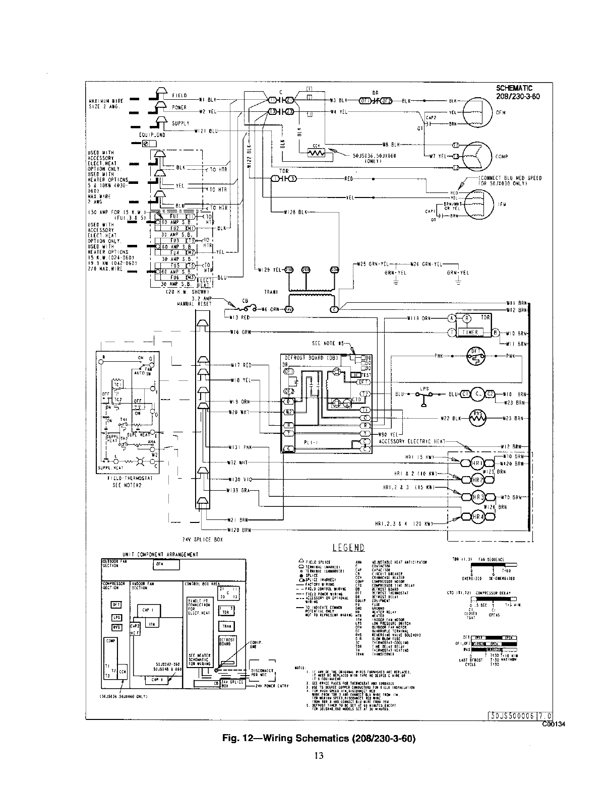
the line wiring splice box (See Fig. 12-17). On all 3-phase units,
connect the leads to the black, yellow, and blue wires (See Fig.
16).
CONNECTING GROUND LEAD TO GROUND LUG
Connect the ground lead to the chassis using the ground lug in the
wiring splice box (See Fig. 16).
ROUTING CONTROL POWER WIRES (24-V)
Form a drip-hiop with the thermostat leads before routing them
into the unit. Route the thermostat leads through grommeted,
low-voltage hole provided in unit into unit control power splice
box (See Fig. 2 and 3). Connect thermostat leads to unit control
power leads as shown in Fig. 15.
The unit transformer supplies 24-v power for complete system
including accessory electrical heater. An automatic-reset circuit
breaker (See Fig. 17) is provided in die 24-v circuit; see the caution
label on the transformer or Fig. 18. Transformer is factory wired
for 230-v operation. If supply voltage is 208-v, rewire transformer
primary as described in Special Procedures for 208-v Operation
section.
10
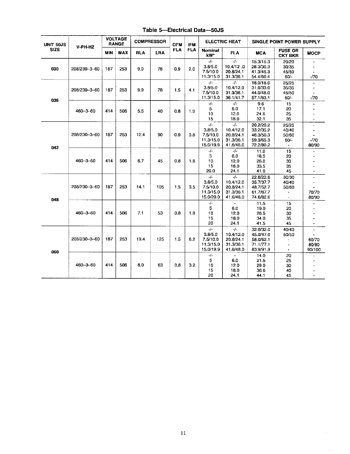
UNIT 50JS
SIZE
O3O
036
O42
048
O60
Table 5_Electrical Data--50JS
VOLTAGE
RANGE
_PH-HZ
MIN MAX
208/230-340 187 253
208/230-3-80 187 253
460-3-60 414 506
COMPRESSOR
RLA LRA
9.9 78
9.9
5.5 40
208/230-3-60 187 253 12.4 90
460-3_60 414 506 6.7 45
208/230_3_0 187 253 14,1 105
460-3-50 414 506 7.1 53
208/230-,3-60 187 253 19.4 125
ELECTRIC HEAT
OFM IFM
FLA FLA Nominal
kW* FLA
-/- -/-
3.8/5.0 10.4/12 .0
0.9 2.0 7.5/10,0 20.8/24,1
11,3/15.0 31.3/36.1
./. -/-
3.8/5.0 10,4/12,0
1.5 4.1 7.5/10.0 31.3/36.1
11,3/15.0 36.1/41.7
./. -/-
66.0
0,8 1.9 10 12.0
15 16.0
./. -/-
3.8/5,0 10.4/12.0
0.9 3.8 7.5/10.0 20.8/24.1
11.3/15.0 31.3/36.1
15.0/19.9 41.6/48.0
-/- ./o
5 6.0
0.8 1.8 10 12.0
15 18.0
20.0 24.1
./. ./.
3.8/5.0 10.4/12.0
1.5 3,5 7.5/10.0 20.8/24.1
11.3/15.0 31.3/36.1
15.0/20.0 41.6/48.0
-/- .
5 6,0
0.8 1.8 10 12.0
15 18.0
26 24.1
-/- -/-
3.3/5.0 10.4/12.0
1.5 5,2 7,5/10.0 20.8/24.1
11,3/15,0 31,3/36.1
15.0/19.9 41.6/48.0
-/- °
5 6.0
0.8 3.2 10 12.0
15 18.0
20 24,1
MCA FUSE OR
CKT BKR
15.3/15.3 20/20
28.3/30.3 30/35
41.3/45.3 45/50
54.4/60.4 60/-
18.0/18.0 25/25
31.0/33.0 35/35
44.0/48.0 45/50
57.1/63.1 60/-
9.6 15
17.1 20
24.6 25
32.1 35
20.2/20.2 25/25
33.2/35.2 40/40
46.3/50.3 50/60
59.5/65.3 60/-
72.2/80.2
11.0 15
18.5 20
26.0 30
33.5 35
41.0 45
22.6/22.6 30/30
35.7/37.7 40/40
48.7/52.7 50/60
61,7/67.7
74.6/82,6
11.5 15
19,0 20
26.5 30
34.0 35
41.5 45
32.0/32.0 40/40
45.0/47.0 50/50
58.0/62.1
71.1/77.1
83.9/91.9
14.0 20
21.5 25
29.0 30
36.6 40
44.1 45
460_._-80 414 506 8.0 63
SINGLE POINT POWER SUPPLY
MOCP
°
-/70
-/70
-/70
80/90
7o o
80/90
60/70
80/80
90/100
It
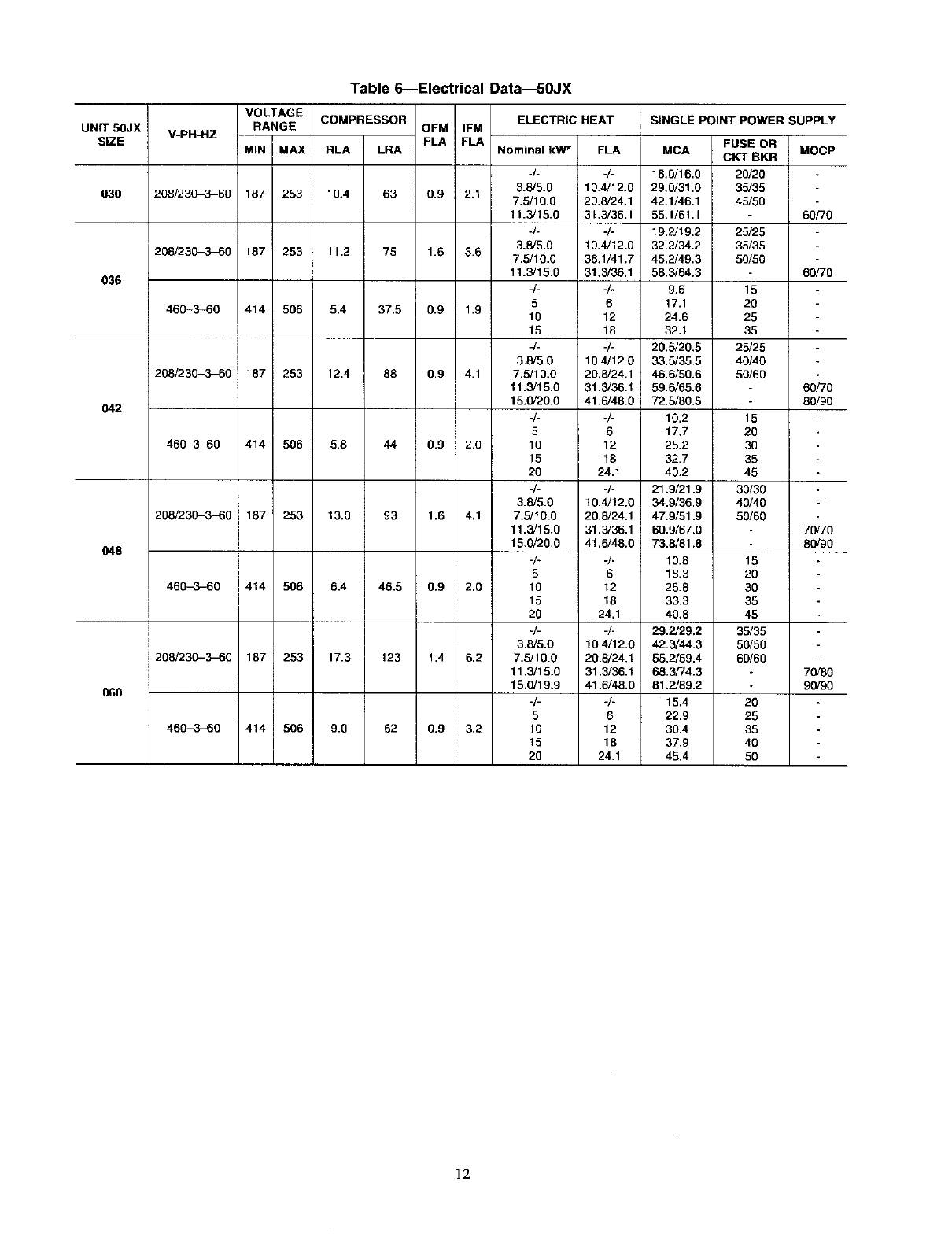
Table 6--Electrical Data--50JX
UNIT 5OJX
SIZE
O30
036
042
048
O60
V-PH-HZ
208/230-3--60
208/230_60
460-:_60
208/230-3_0
460-3_0
208/230-3-60
460_3_0
208/230_3_30
460-3_0
VOLTAGE
RANGE COMPRESSOR OFM IFM
FLA FLA
MIN MAX RLA LRA
187 253 10.4 63 0.9 2,1
187' 253 11.2 75 1.6 3.6
414 506 5.4 37.5 0.9 1.9
187 253 12.4 88 0.9 4.1
414 506 5.8 44 0.9 2.9
187 253 13.0 93 1.6 4.1
414 506 6.4 46.5 0.9 2.0
187 253 17.3 123 1.4 6.2
414 506 9.0 62 0.9 3.2
ELECTRIC HEAT SINGLE POINT POWER SUPPLY
Nominal kW* FLA MCA
-/- -/- 16.0/16.0
3.8/5.0 10.4/12.0 29.0/31.0
7.5/10.0 20.8/24.1 42.1/46.1
11.3/15.0 31.3/36.1 55.1/61,1
-/- -/- 19.2119.2
3.8/5.0 10.4/12.0 32.0/34.2
7.5/10.0 36.1/41.7 45.2/49.3
11.3/15.0 31.3/36.1 58.3/64.3
-/- 4- 9.6
56 17.1
10 12 24.6
15 18 32.1
-/- -/- 20.5/20.5
3.8/5.0 10.4/12.0 33,5/35.5
7.5/10,9 29.8/24.1 46.6/50.6
11.0/15.0 31.0/36.1 59.6/65.6
15.0/20.0 41.6/48.0 72,5/80.5
-/- -/- 10.2
5 6 17.7
10 12 25.2
15 18 32.7
20 24.1 40.2
-/- 4- 21.9/21.9
3.6/5.0 10.4/12.0 34.9/36.9
7.5/10,0 20.8/24.1 47.9/51.9
11.3/15,0 31.3/36.1 60.9/67.0
15.0/20.0 41.5/48.0 73.8/81.8
4- -/- 10.8
5 6 18.3
10 12 25.8
15 18 33.3
20 24.1 40.8
-/- -/- 29.2/29.2
3.8/5.9 10.4/12,0 42.3/44.3
7.5/10.0 20.6/24.1 55,2/59.4
11.3/15.0 31.3/36.1 68.3/74.3
15.9/19.9 41.6/48.0 81.2/89.2
-/- -/- 15.4
5 6 22.9
10 12 30.4
15 18 37.9
20 24.1 45.4
FUSE OR
CKT BKR
20/20
35/35
45/50
25/25
35/35
50/50
15
20
25
35
25/25
40/40
59/60
15
20
30
35
46
30/30
40/40
50/60
15
20
30
35
45
35/35
50/50
60/60
20
25
35
40
50
MOCP
60/70
60/70
60/70
80/90
70/70
80/90
70i80
90/90
12
fII_L_IELO _1 _L E-
-- ,,EL
i_ SUPPLY
--WI2I 8LU
EOUIP.GNO
USED WITH _I_-- -_" - !
ACCCSSORV
ELECT.EkI --I__
OPTION ONLY BL
I-
US£1) WITH
N[AT[R OPTIONSN Pmm_H' _ L
060) I • _ lO HIR
MAXWIldE2Ai(G i '___= _
(50 Ak(P FOE 15 KI_ ) W128 BLK--
IFUI 3 /_ 5) TO
US 0 IVT I _HI_
ACCESSORY _ Iuz MI i_ BLK--
LCI Hkl I 30,kMPSB _
OPTION ON Y _ TO
USED WIIH _ GO AMP S8HTR
HEATER OPTIONS _YEL--
15 KW [024 060) _ 30 kWP SB _ i
19 9 KW (042 0601 I_
i _euect BLU--
(20 K W SHOV_,_} TRANI
3 2 AMP
MA,UAL RESEl_ C_,.,-_
q
ON
F AUTO S
_W
_;.PPLT._uPL.E_- = _
tW2--
rlEL_ THERMO_IAT I
SEE NOTE#2
I--
-RED
VEL
_)6 GRN
NIT RED
-------_18 YE_
_19 ORN
_20 WHT
_131 pN_
_y2 WHI
_'130 VIO
_133 GRA_
SEE NOTE 15_
R -- C)ll
_21BRN---
_12o BRN
2(V SPLICE BOX
[CONNECT BLU RED SPED
L -- FOR 50JX030 ONLY)
GRN-YEL_26 GRN YEL_
GEN-YEL GRN-y[[
WIT BR_
_ i_ _
_70 5RN--
RN
HRI 2 3 _ _ [20 KWI_
I
UNIT COWPONENI ARRANGEWENT
iouI_ F_N
_SECIIOU
,_r_ost
rl{Lo S_LIC( _H_ _BJUST_BL(W_*_ _NT_I_I_
ru fUS{
O_W OUt_ r_ _tO_
IDN (L)k r_I _EOUEN¢[
CLOSES OENS
T_T
II iZ _ SDa%04_'O_OSOJS04_I 0_I
/
FOI IIII_
!50JS5OOOOG(? 0
GO(
Fig. 12--Wiring Schematics (208/230-3-60)
13
134
_AXIMU_ WIR[ _ _ FIEL_ il BLK
SIZE 2 AWG -- _2 YEL--_ /
- _,. _o_
[OUIP _ND
ACCESSORY
ELECT HEAT
OPTION ONLY --
HEATER OPTIDNS Y[L
5,10,15 _ _0 KW
WAXWIR [ _ g_
AWG L-L_--BE
c m 50-1BVIATIC
TEL-- CApZ YEL OFM
--W16 GRN
_25 GRN YEL_?6 GRN-YEL_
GRN Y[L GRN YEL
_z #
UNIT COMPONENT ARRANGEMENT
SEE NOTE
PLI-I
Te_ (I _
[WEmOIZED DE-ENEe_Ep
_D _ILI_ COWpRES_ORDELay
F:_
J[ou_e
_F_OS _ _W_ _m llW[D[L_ ffL*_
_O_W_ _ffs_I iF_ m IM{OlI_,_L II_[_F_m=Is.[__( e[eL_:E_
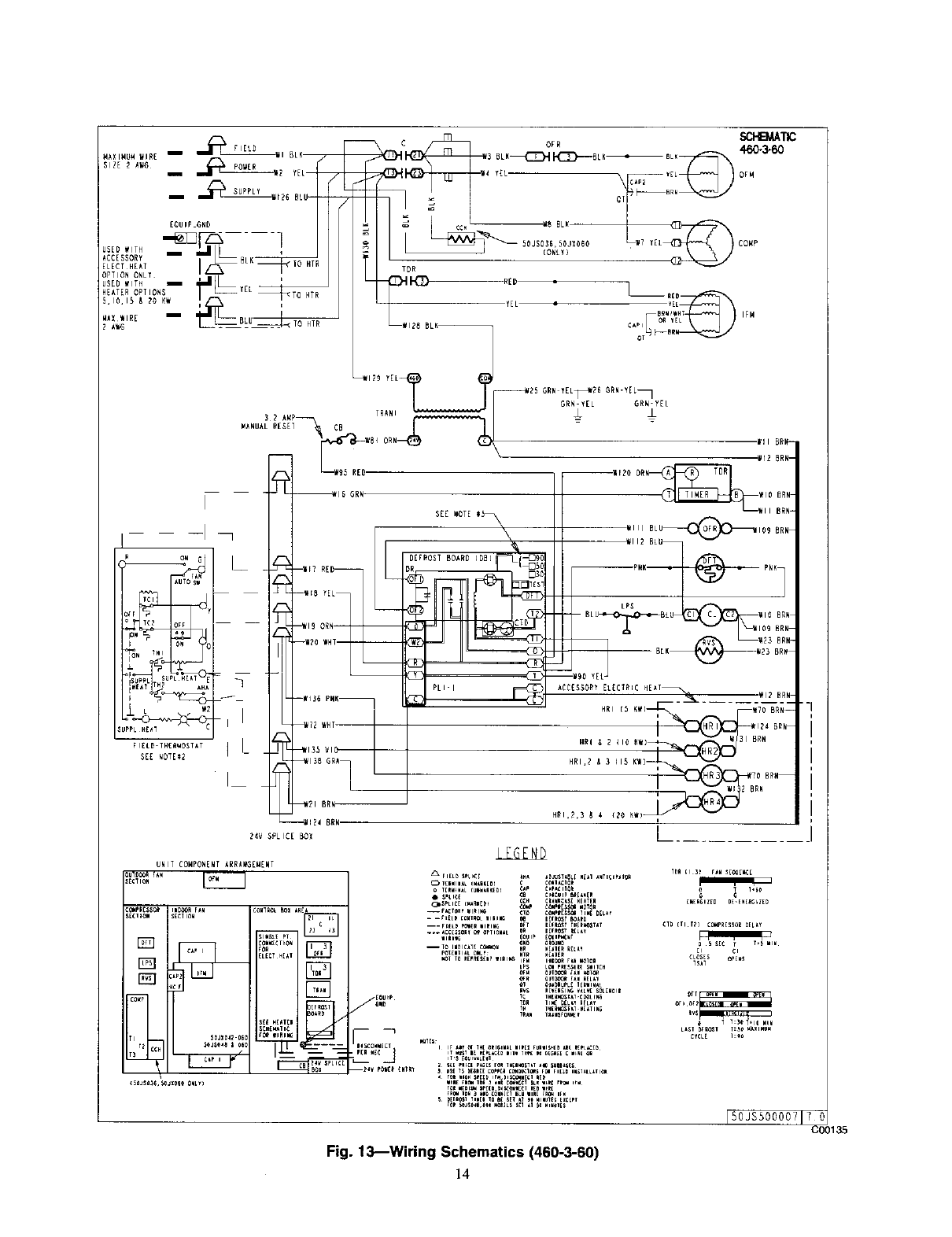
Fig. 13--Wiring Schematics (460-3-60)
14
150JS500007170
C00135
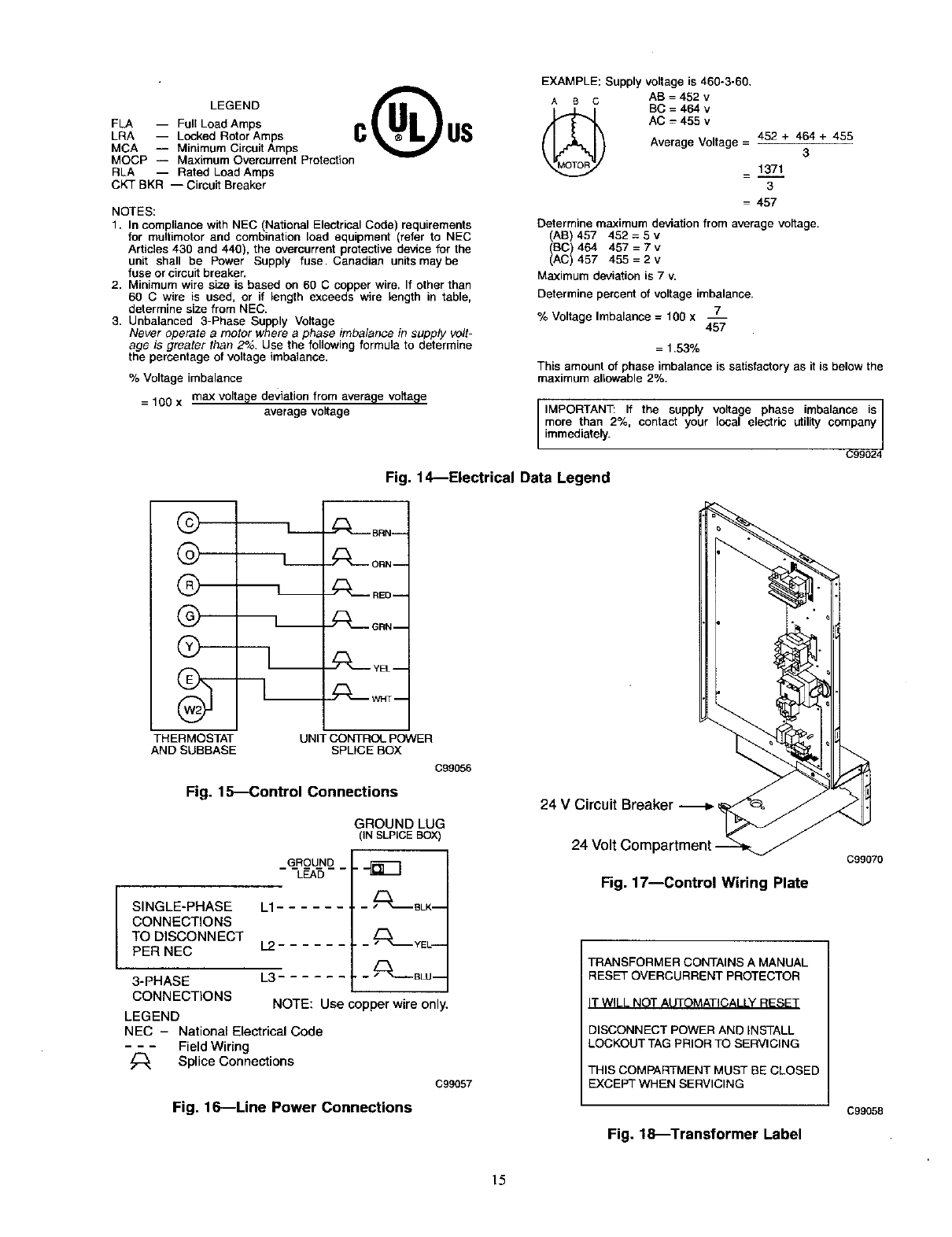
EXAMPLE: Supply voltage is 460-3-60.
LEGEND C US ,, o o AB=452v
(_ BC = 464 v
FLA -- Full Load Amps AC = 455 v
LRA -- Locked Rotor Amps Average Voltage = 452 + 464 + 455
MCA -- Minimum Circuit Amps 3
MOCP -- Maximum Overcurrent Protection
RLA -- Rated Load Amps = 1371
CKT BKR -- Circuit Breaker 3
= 457
NOTES:
1. In compliance with NEC (National Electrical Code) requirements
for muitimotor and combination load equipment (refer to NEC
Articles 430 and 440), the overcurrent protective device for the
unit shall be Power Supply fuse. Canadian units may be
fuse or circuit breaker.
2. Minimum wire size is based on 60 C copper wire. If other than
60 C wire is used, or if length exceeds wire length in table,
determine size from NEC.
3. Unbalanced 3-Phase Supply Voltage
Never operate a motor where a phase tmbalance in supply volt-
age is greater than 2%, Use the following formula to determine
the percentage of voltage imbalance.
%Voltage imbalance
= 100 x max voltage deviation from average voltage
average voltage
Determine maximum deviation from average voltage.
(AB) 457 452=5v
(BC) 464 457=7v
(AC) 457 455=2v
Maximum deviation is 7 v.
Determine percent of voltage imbalance.
% Voltage Imbalance = 100 x 7
457
= 1.53%
This amount of phase imbalance is satisfactory as it is below the
maximum allowable 2%.
IMPORTAN]_ If the supply voltage phase imbalance is]
more than 2%, contact your local electric utility company/
immediately. /
C99024
Fig. 1€--Electrical Data Legend
©
Q---
THERMOSTAT
AND SUBBASE
L.-- _.__ BRN_-
----L---- o.N-
_ RED --
_GRN--
UNIT CONTROL POWER
SPLICE BOX
C99056
Fig. 15---Control Connections
SINGLE-PHASE
CONNECTIONS
TO DISCONNECT
PER NEC
3-PHASE
CONNECTIONS
LEGEND
NEC - National Ele_rical Code
- - - Field Wiring
_ Splice Conne_ions
GROUND LUG
IN SLPICEBOX)
GROUND
"L_AS--_
L1 _BLK--
L2 ........ _YEL--
L3 ........ _C_-"-BLU --
NOTE: Use copper wire only.
Fig. 16---Line Power Connections
C99057
24 V Circuit Breaker
Fig. 17--Control Wiring Plate
TRANSFORMER CONTAINS A MANUAL
RESET OVERCURRENT PROTECTOR
IT WILL NOT AUTOMATICALLY RESET
DISCONNECT POWER AND INSTALL
LOCKOUT TAG PRIOR TO SERVICING
THIS COMPARTMENT MUST BE CLOSED
EXCEPT WHEN SERVICING
C99070
C99058
Fig. 18_Transformer Label
15
SPECIAL PROCEDURES FOR 208-V OPERATION
1. Disconnect the yellow primary lead from the transformer. See
unit wiring label (See Fig. 12).
2. Connect the yellow primary lead to the transformer terminal
labeled 200-v.
Indoor blower-motor speeds may need to be changed for 208-v
operation. Refer to indoor airflow and airflow adjustments section.
PRE-START-UP
Failure to observe the following warnings could result in
serious personal injury or death:
1. Follow recognized safety practices and wear protective
goggles when checking or servicing refrigerant system.
2. Do not operate compressor or provide any electric power to
unit unless compressor terminal cover is in place and
secured.
3. Do not remove compressor terminal cover until all electri-
cal sources are disconnected and tagged.
4. Relieve and recover all refrigerant from system before
touching or disturbing anything inside terminal box if
refrigerant leak is suspected around compressor terminals.
5. Never attempt to repair soldered connection while refrig-
erant system is under pressure.
6. Do not use torch to remove any component. System
contains oil and refrigerant under pressure.
To remove a component, wear protective goggles and
proceed as follows:
a. Shut off electrical power to unit and install lockout tag.
b. Relieve and reclaim all refrigerant from system using
both high- and low-pressure ports.
c. Cut component connecting tubing with tubing cutter and
remove component from unit.
d. Carehiliy unsweat remaining tubing stubs when neces-
sary. Oil can ignite when exposed to torch flame.
Use the Start-Up Checklist supplied at the end of this book and
proceed as follows to inspect and prepare the unit for initial
start-up:
1. Remove access panel.
2. Read and follow instructions on all DANGER, WARNING,
CAUTION, and INFORMATION labels attached to, or
shipped with, unit.
3. Make the following inspections:
a. Inspect for shipping and handling damages such as broken
lines, loose parts, disconnected wires, etc.
b. Inspect for oil at all refrigerant tubing connections and on
unit base. Detecting oil generally indicates a refrigerant
leak. Leak-test all refrigerant tubing connections using
electronic leak detector, or liquid-soap solution. If a refrig-
erant leak is detected, see following Check for Refrigerant
Leaks section.
c. Inspect all field and factory-wiring connections. Be sure
that connections are completed and tight.
d. Ensure wires do not touch refrigerant tubing or sharp
sbeetmetal edges.
e. Inspect coil fins. If damaged during shipping and handling,
carefully straighten Pms with a fin comb.
4. Verify the following conditions:
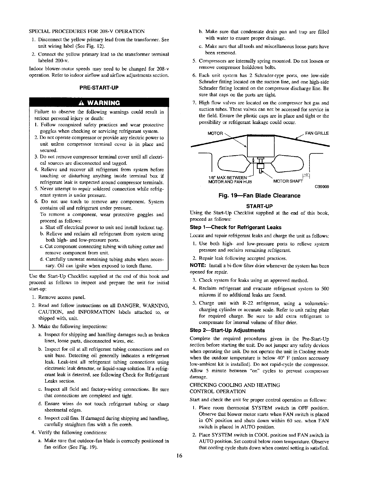
a. Make sure that outdoor-fan blade is correctly positioned in
fan orifice (See Fig. 19).
16
b. Make sure that condensate drain pan and trap are filled
with water to ensure proper drainage.
c. Make sure that all tools and miscellaneous loose parts have
been removed.
5. Compressors are internally spring mounted. Do not loosen or
remove compressor holddown bolts.
6. Each unit system has 2 Schrader-type port.s, one low-side
Schrader fitting located on the suction line, and one high-side
Schrader fitting located on the compressor discharge line. Be
sure that caps on the ports are tight.
7. High flow valves are located on the compressor hot gas and
suction tubes. These valves can not be accessed for service in
the field. Ensure the plastic caps axe in place and tight or the
possibility or refrigerant leakage could occur.
MOTORAND FANHUB MOTORSHAFT
C99009
Fig. 19_Fan Blade Clearance
START-UP
Using the Start-Up Checklist supplied at the end of this book,
proceed as follows:
Step 1--Check for Refrigerant Leaks
Locate and repair refrigerant leaks and charge the unit as follows:
I. Use both high- and low-pressure ports to relieve system
pressure and reclaim remaining refrigerant.
2. Repair leak following accepted practices.
NOTE: Instal] a bi-fhiw filter drier whenever the system has been
opened for repair.
3. Check system for leaks using an approved method.
4. Reclaim refrigerant and evacuate refrigerant system to 500
microns if no additional leaks are found.
5. Charge unit with R-22 refrigerant, using a volumetric-
charging cylinder or accurate scale. Refer to unit rating plate
for required charge. Be sure to add extra refrigerant to
compensate for internal volume of filter drier.
Step 2---Start-Up Adjustments
Complete the required procedures given in the Pre-Start-Up
section before starting the unit. Do not jumper any safety devices
when operating the unit. Do not operate the unit in Cooling mode
when the outdoor temperature is below 40 ° F (unless accessory
low-ambient kit is installed). Do not rapid-cycle the compressor.
Allow 5 minute between "on" cycles to prevent compressor
damage.
CHECKING COOLING AND HEATING
CONTROL OPERATION
Start and check the unit for proper control operation as follows:
I. Place room thermostat SYSTEM switch in OFF position.
Observe that blower motor starts when FAN switch is placed
in ON position and shuts down within 60 sec. when FAN
switch is placed in AUTO position.
2. Place SYSTEM switch in COOL position and FAN switch in
AUTO position. Set control below room temperature. Observe
that cooling cycle shuts down when control setting is satisfied.
Bypass
Position
_rF
OUTDOOR COIL
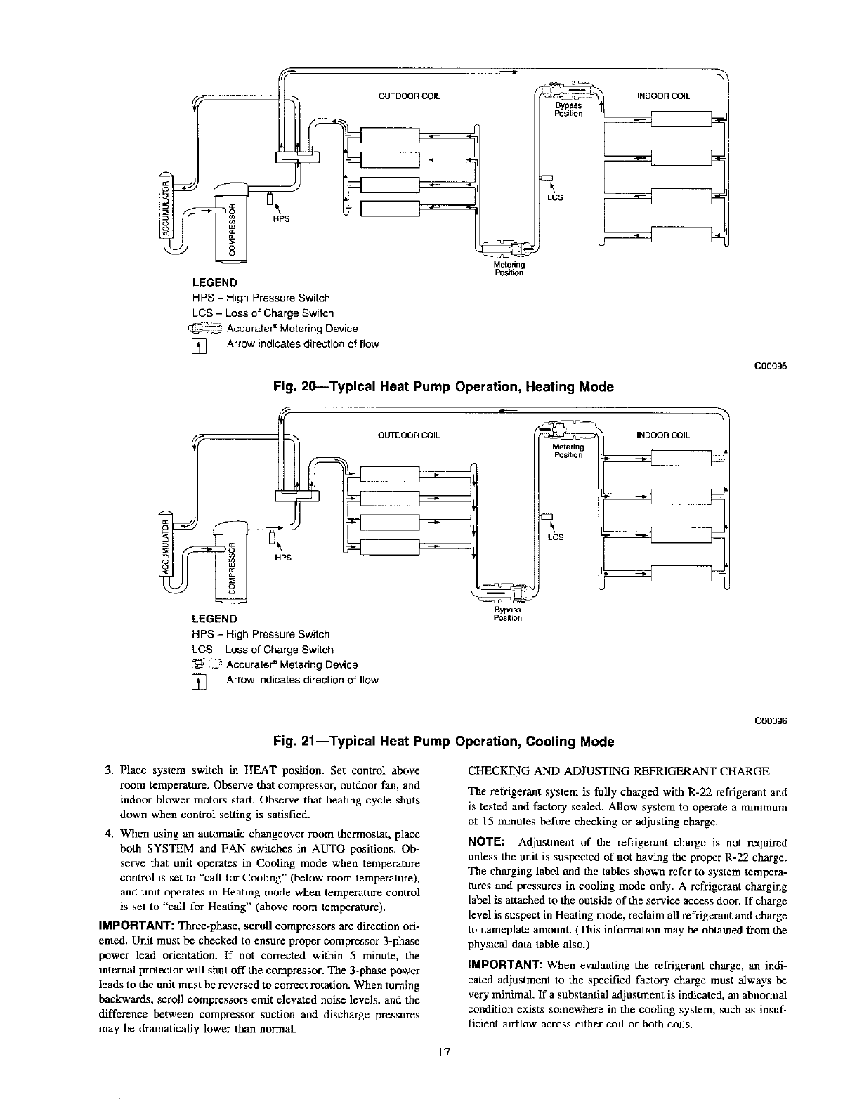
LEGEND
HPS - High Pressure Switch
LCS - Loss of Charge Switch
_j_ Accurater e Metering Device
] Arrow indicates direction of flow
Metering
Position
LCS
Fig. 20--Typical Heat Pump Operation, Heating Mode
OUTDOOR
LEGEND
HPS - High Pressure Switch
LCS -Loss of Charge Switch
"_ Accurate# Metering Device
] Arrow indicates direction of flow
Bypa_
Pos_ion
Metering
Position
LCS
INDOOR COIL
INDOOR COIL
C00095
Fig. 21--Typical Heat Pump Operation, Cooling Mode
C00096
3. Place system switch in HEAT position. Set control above
room temperature. Observe that compressor, outdoor fan, and
indoor blower motors start. Observe that heating cycle shuts
down when control setting is satisfied.
4. When using an automatic changeover room thermostat, place
both SYSTEM and FAN switches in AUTO positions. Ob-
serve that unit operates in Cooling mode when temperature
control is set to "call for Cooling" (below room temperature),
and unit operates in Heating mode when temperature control
is set to "call for Heating" (above room temperature).
IMPORTANT: Three-phase, scroll compressors are direction ori-
ented. Unit must be checked to ensure proper compressor 3-phase
power lead orientation. If not corrected within 5 minute, the
internal protector will shut off the compressor. The 3-phase power
leads to the unit must be reversed to correct rotation. When turning
backwards, scroll compressors emit elevated noise levels, and the
difference between compressor suction and discharge pressures
may be dramatically lower than normal.
CHECKING AND ADJUSTING REFRIGERANT CHARGE
The refrigerant system is fully charged with R-22 refrigerant and
is tested and factory sealed. Allow system to operate a minimum
of 15 minutes before checking or adjusting charge.
NOTE: Adjustment of the refrigerant charge is not required
unless the unit is suspected of not having the proper R-22 charge.
The charging label and the tables shown refer to system tempera-
tures and pressures in cooling mode only. Arefrigerant charging
label is attached to the outside of the service access door. If charge
level is suspect in Heating mode, reclaim all refrigerant and charge
to nameplate amount. (This information may be obtained from the
physical data table also.)
IMPORTANT: When evaluating the refrigerant charge, an indi-
cated adjustment to the specified factory charge must always be
very minimal. If a substantial adjustment is indicated, an abnormal
condition exists somewhere in the cooling system, such as insuf-
ficient airflow across either coil or both coils.
17
7O
Balance Point Worksheet
6O
so
mg
_o
m_ ,0
m_
80
:z:o_ 30
_._ 20
lO
-10 0 10 17 20 30 40 47 50
OutdoorAir Temp (Deg F)
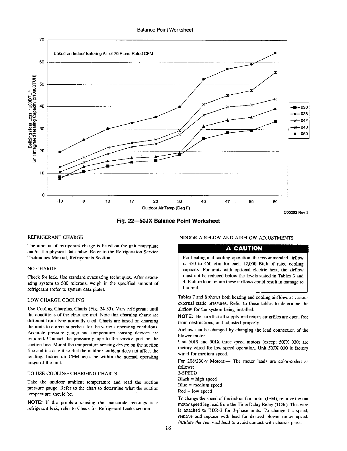
Fig. 22--50JX Balance Point Worksheet
6O
C00093 Rev 2
REFRIGERANT CHARGE
The amount of refrigerant charge is Listed on the unit nameplate
and/or the physical data table. Refer to the Refrigeration Service
Techniques Manual, Refrigerants Section.
¥_ [__.'luhnl[.]H
NO CHARGE
Check for leak. Use standard evacuating techniques. ARer evacu-
ating system to 500 microns, weigh in the specified amount of
refrigerant (refer to system data plate).
LOW CHARGE COOLING
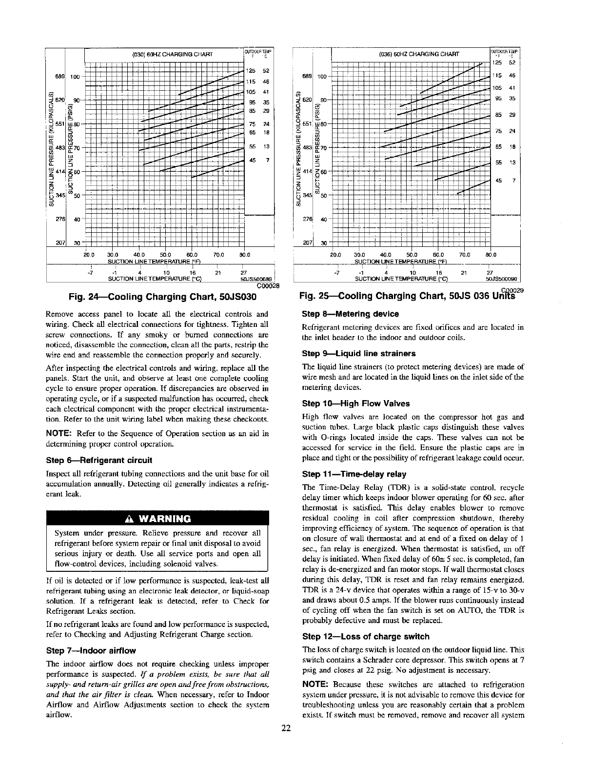
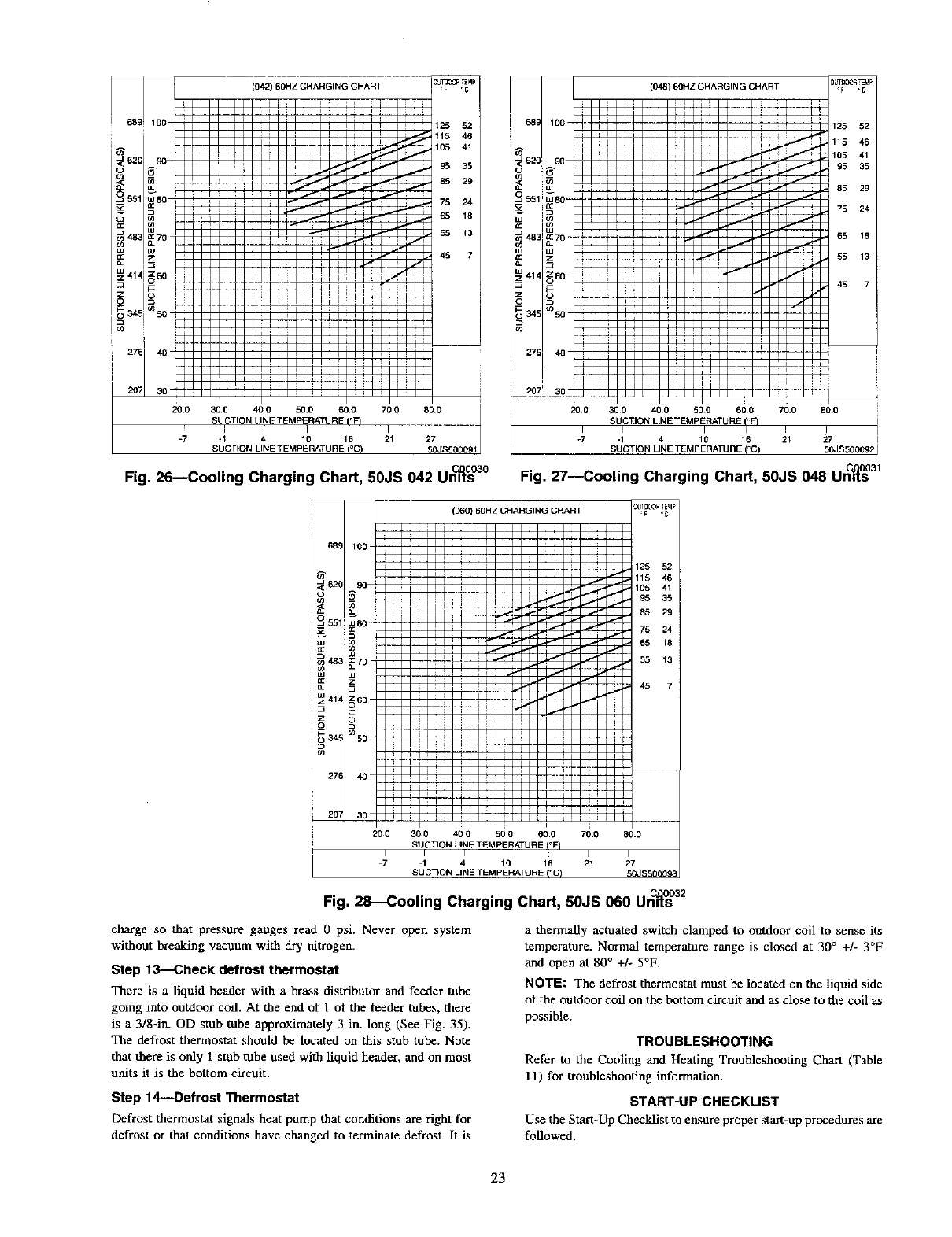
Use Cooling Charging Charts (Fig. 24-33). Vary refrigerant until
the conditions of the chart are met. Note that charging charts are
different from type normally used. Charts are based on charging
the units to correct superheat for the various operating conditions.
Accurate pressure gauge and temperature _nsnig devices are
required. Connect the pressure gauge to the service port on the
suction line. Mount the temperature sensing device on the suction
line and insulate it so that the outdoor ambient does not affect the
reading. Indoor air CFM must be within the normal operating
range of the unit.
TO USE COOLING CHARGING CHARTS
Take the outdoor ambient temperature and read the suction
pressure gauge. Refer to the chart to determine what the suction
temperature should be.
NOTE: If the problem causing the inaccurate readings is a
refrigerant leak, refer to Check for Refrigerant Leaks section.
INDOOR AIRFLOW AND AIRFLOW ADJUSTMENTS
18
For heating and cooling operation, the recommended airflow
is 350 to 450 cfm for each 12,000 Btuh of rated cooling
capacity. For units with optional electric heat, the airflow
must not be reduced below the levels stated in Tables 3 and
4. Failure to maintain these airflows could result in damage to
the unit.
Tables 7 and 8 shows both heating and cooling airflows at various
external static pressures. Refer to these tables to determine the
airflow for the system being installed.
NOTE: Be sure that all supply-and return-air grilles are open, free
from obstructions, and adjusted properly.
Airflow can be changed by changing the lead connection of the
blower motor.
Unit 50JS and 50JX three-speed motors (except 50JX 030) are
factory wired for low speed operation. Unit 50JX 030 is factory
wired for medium speed.
For 2081230-v Motors:-- The motor leads are color-coded as
follows:
3-SPEED
Black = high speed
Blue = medium speed
Red =low speed
To change the speed of the indoor fan motor (IFM), remove die fan
motor speed leg lead from the Time Delay Relay (TDR). This wire
is attacbed to TDR-3 for 3-phase units. To change the speed,
remove and replace with lead for desired blower motor speed.
ln,Tulate the removed lead to avoid contact with chassis parts.
Balance Point Worksheet
70
60
i-
ca 50
_o
o_
go
...__ 40
C
30
Im
_q:3
ca_
_E 2o
lO
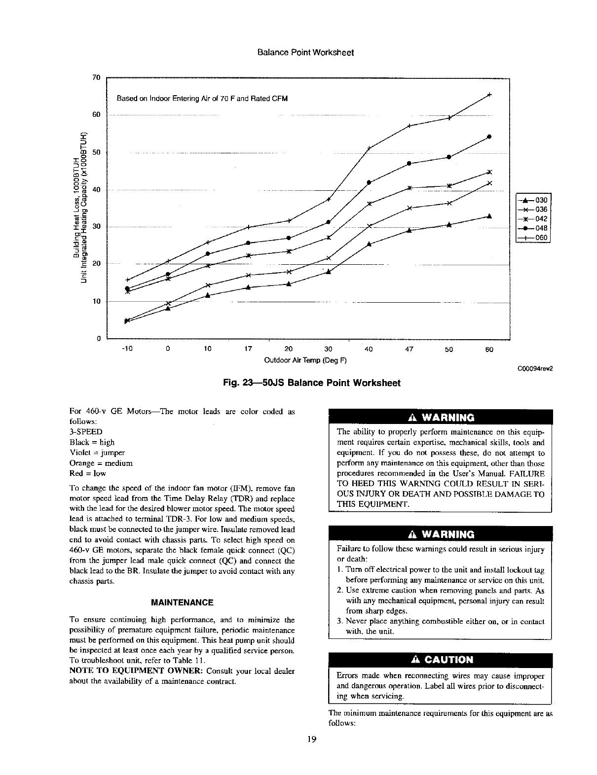
Based on Indoor Entering Air of 70 F and Rated CFM
-10 0 10 17 20 30
Outdoor Air Temp (Deg F)
40
Fig. 23_50JS Balance Point Worksheet
47 50 6O
C00094rev2
For 460-v GE Motors_The motor leads are color coded as
follows:
3-SPEED
Black = high
Violet = jumper
Orange = medium
Red = low
To change die speed of the indoor fan motor (IFM), remove fan
motor speed lead from the Time Delay Relay (TDR) and replace
with the lead for the desired blower motor speed. The motor speed
lead is attached to terminal TDR-3. For low and medium speeds,
black must be connected to the jumper wire. Insulate removed lead
end to avoid contact with chassis parts. To select high speed on
460-v GE motors, separate die black female quick connect (QC)
from the jumper lead male quick connect (QC) and connect the
black lead to the BR. Insulate the jumper to avoid contact with any
chassis parts.
MAINTENANCE
To ensure continuing high performance, and to minimize the
possibility of premature equipment failure, periodic maintenance
must be performed on tiffs equipment. This heat pump unit should
be inspected at least once each year by a qualified service person.
To troubleshoot unit, refer to Table 11.
NOTE TO EQUIPMENT OWNER: Consult your local dealer
about the availability of a maintenance contract.
The ability to properly perform maintenance on this equip-
ment requires certain expertise, mechanical skills, tools and
equipment. If you do not possess these, do not attempt to
perform any maintenance on this equipment, other than those
procedures recommended in the User's Manual. FAILURE
TO HEED THIS WARNING COULD RESULT IN SERI-
OUS INJURY OR DEATH AND POSSIBLE DAMAGE TO
THIS EQUIPMENT.
Failure to follow these warnings could result in serious injury
or death:
I. Turn off electrical power to die unit and install lockout tag
before performing any maintenance or service on this unit.
2. Use extreme caution when removing panels and parts. As
with any mechanical equipment, personal injury can result
from sharp edges.
3. Never place anything combustible either on, or in contact
with, the unit.
19
ing when servicing.
The minimum maintenance requirements for this equipment are _.s
follows:
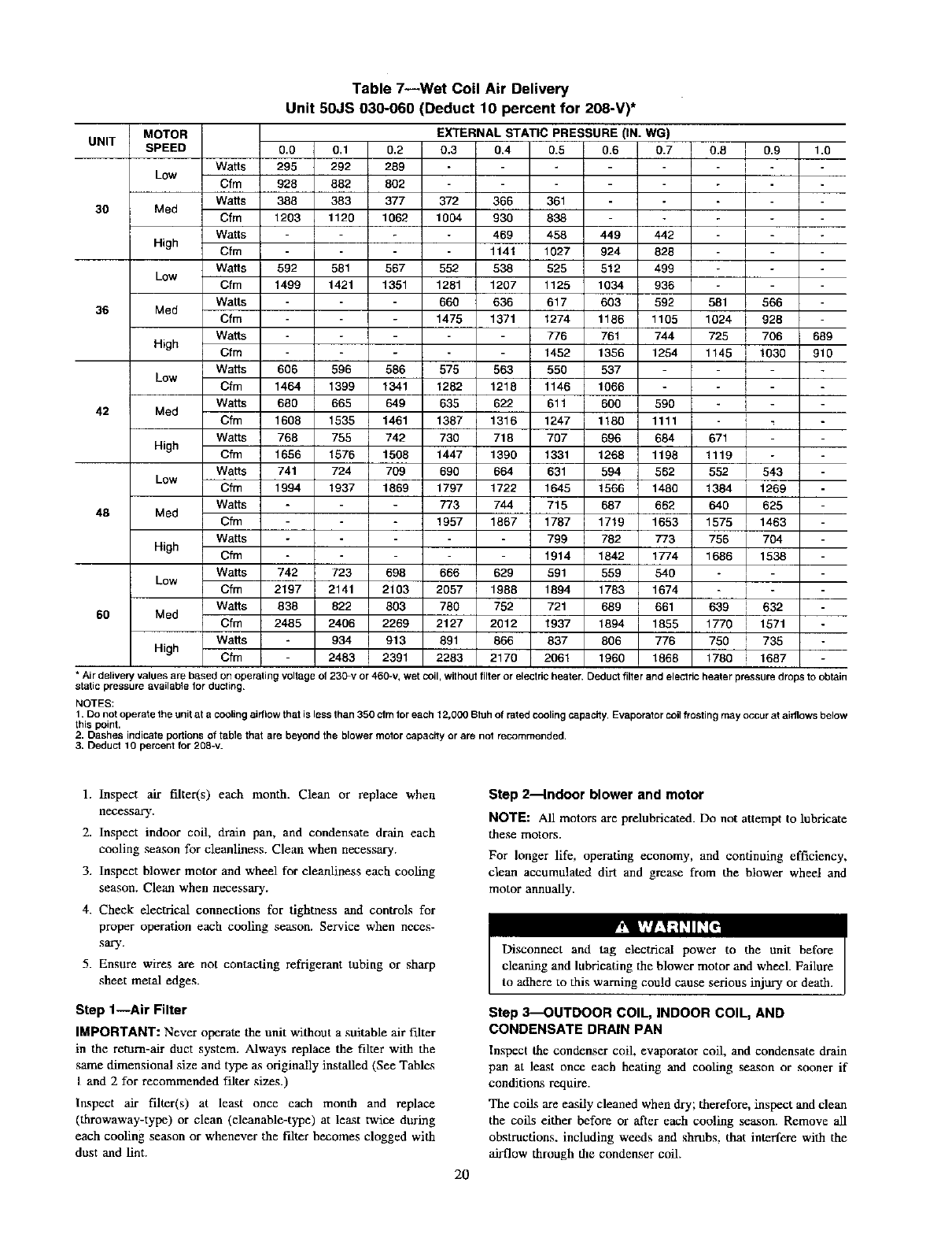
Table 7--Wet Coil Air Delivery
Unit 50JS 030-060 (Deduct 10 percent for 208-V)*
UNIT
3O
36
42
48
6O
MOTOR EXTERNAL STATIC PRESSURE (IN. WG)
SPEED 0.0 0.1 0.2 0.3 0.4 0.5 0.6 0.7
Watts 295 292 289
Low Cfm 928 882 802
WaRs 388 383 377 372 366 361
Med Cfm 1203 1120 1062 1004 930 838
W_ts 469 458 449 442
High Cfm 1141 1027 924 828
W_ts 592 581 567 552 538 525 512 499
Low Cfm 1499 1421 1351 1281 1207 1125 1034 936
Watts 660 636 617 603 592
Med Cfm 1475 1371 1274 1186 1105
WaRs 776 761 744
High Cfm 1452 1356 1254
WaRs 606 596 586 575 563 550 537
Low Cfm 1464 1399 1341 1282 1218 1146 1066
WaRs 680 665 649 635 622 611 600 590
Med Cfm 1608 1535 1461 1387 1316 1247 1180 1111
Watts 768 755 742 730 718 797 596 684
High Cfm 1656 1576 1508 1447 1396 1331 1268 1198
WaRs 741 724 709 690 664 631 594 562
Low Cfm 1994 1937 1869 1797 1722 1645 1566 1480
WaRs 773 744 715 667 662
Med Cfm 1957 1867 1787 1719 1653
WaRs 799 782 773
High Cfm 1914 1842 1774
WaRs 742 723 698 666 629 591 559 540
Low Cfm 2197 2141 2103 2057 1988 1894 1783 1674
W_ts 838 822 803 760 752 721 689 661
Med Cfm 2485 2406 2269 2127 2012 1937 1894 1855
WaRs 934 913 691 666 837 806 776
High Cfm 2483 2391 2283 2170 2061 1960 1868
0.8 0.9 1.0
I
I
I
581 566
1024 i 928
725 ] 706
1145 ] 1030
i
1
671 1
1119 I
552 543
1384 1269
640 625
1575 1463
756 704
1686 1538
[
I
639 632
1770 ] 1571
750 [735
1780 i 1687
689
910
* Air delivery values are based on operating voltage of 230_v or 460-v, wet coil, withoutfilter or electric heater. Deduct filter and electric heater pressure drops to obtain
static pressure available for ducting.
NOTES:
1. Do not operate the unit at a cooling airflow that is less than 350 cfm for each 12,000 Btuh of rated cooling capacity. Evaporator coilfrosting may occur at airflows below
this point.
2. Dashes indicate podions of table that are beyond the blower motor capacity or are not recommended.
3. Deduct 10 percent for 208-v.
1. Inspect air filter(s) each month. Clean or replace when
necessary.
2. Inspect indoor coil, drain pan, and condensate drain each
cooling season for cleanliness. Clean when necessary.
3. Inspect blower motor and wheel for cleanliness each cooling
season. Clean when necessary.
4. Check electrical connections for tightness and controls for
proper operation each cooling season. Service when neces-
sary.
5. Ensure wires are not contacting refrigerant tubing or sha_
sheet metal edges.
Step 1--Air Filter
IMPORTANT: Never operate the unit without a suitable air filter
in the return-air duct system. Always replace the fiker with the
same dimensional size and type a_soriginally installed (See Tables
I and 2 for recommended fdter sizes.)
Inspect air filter(s) at least once each month and replace
(throwaway-type) or clean (cleanable-type) at lea.st twice during
each cooling season or whenever the f-alterbecomes clogged with
dust and tint.
Step 2--Indoor blower and motor
NOTE: All motors are prelubricated. Do not attempt to lubricate
these motors.
For longer life, operating economy, and continuing efficiency,
clean accumulated dirt and grease from the blower wheel and
motor annually.
20
Disconnect and tag electrical power to the unit before
cleaning and lubricating the blower motor and wheel. Failure
to adhere to this warning could cause serious injury or death.
Step 3--OUTDOOR COIL, INDOOR COIL, AND
CONDENSATE DRAIN PAN
Inspect the condenser coil, evaporator coil, and condensate drain
pan at least once each heating and cooling season or sooner if
conditions require.
The coils are easily cleaned when dry; therefore, inspect and dean
the coils either before or after each cooling season. Remove all
obstructions, including weeds and shrubs, that interfere with the
airflow through the condenser coil.
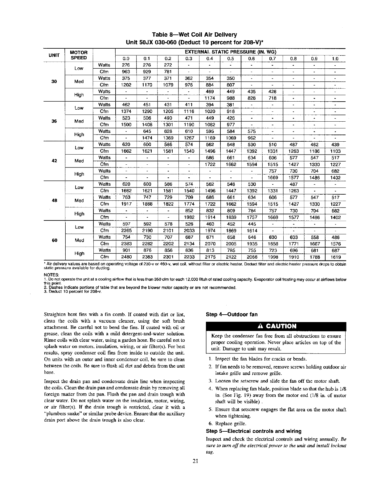
Table 8_Wet Coil Air Delivery
Unit 50JX 030-060 (Deduct 10 percent for 208-V)*
UNIT
3O
36
42
48
60
MOTOR EXTERNAL STATIC PRESSURE (IN. WG)
SPEED 0.O 0.1 0.2 0.3 0.4 0.5 0.6 0.7
Watts 276 276 272
Low Cfm 963 929 781
Watts 375 377 371 362 354 350
Med Cfm 1202 1170 1079 976 884 807
Wa_s 469 449 435 428
High Cfm 1174 988 828 718
WaHs 462 451 431 411 394 381
Low Cfm 1374 1290 1205 1116 1020 916
Watts 523 506 499 471 449 426
Med Cfm 1500 1408 1301 1190 1082 977
Watts 645 628 610 595 584 575
High Cfm 1474 1369 1267 1169 1069 962
Watts 620 600 586 574 562 548 530 510
Low Cfm 1662 1621 1581 1540 1496 1447 1392 1331
Wa_s 686 661 634 606
Med Cfm 1722 1662 1594 1515
WaHs 757
High Cfm 1669
WaSs 620 600 586 574 562 548 530
Low Cfm 1662 1621 1581 1540 1496 1447 1392 1331
Watts 763 747 729 709 686 661 634 606
Med Cfm 1917 1868 1822 1774 1722 1662 1594 1515
Wa_s I 852 832 809 784 757
High Cfm I 1982 1914 1839 1757 1669
Watts 597 592 578 526 460 452 445
Low Cfm 2265 2190 2101 2033 1974 1869 1614
Watts 754 730 707 687 671 658 646 630
Med Cfm 2383 2282 2202 2134 2070 2005 1935 1858
Wa_s 901 876 856 836 813 785 755 723
High Cfm 2480 2383 2301 2233 2175 2122 2066 1998
0.8 0.9 1.0
487 462 439
1263 1186 1103
577 547 517
1427 1330 1227
730 704 682
1577 1486 1402
487
1263
577 547 517
1427 1330 1227
730 704 682
1577 1486 1402
603 558 486
1771 1667 1576
696 681 687
1910 1788 1619
* Air delivery values are based on operating voltage of 230-v or 460-v, wet coil, without filter or elect nc heater. Deduct filter and electdc heater pressure drops to obtain
static pressure available for ducting.
NOTES:
1. Do not operate the unit at a cooling airflow that is less than 350 cfm for each 12,000 Btuh of rated cooling capacity. Evaporator coil frosting may occur at airflows below
this point.
2. Dashes indicate portions of table that are beyond the blower motor capacity or are not recommended.
3. Deduct 10 percent for 208-v.
Straighten bent fins with a fin comb. If coated with dirt or lint,
clean the coils with a vacuum cleaner, using the soft brush
attachment. Be careful not to bend the fins. If coated with oil or
grease, clean the coils with a mild detergent-and-water solution.
Rinse coils with clear water, using a garden hose. Be careful not to
splash water on motors, insulation, wiring, or air filter(s). For best
result.s, spray condenser coil fins from inside to outside the unit.
On units with an outer and inner condenser coil, be sure to clean
between the coils. Be sure to flush ail dirt and debris from the unit
base.
Inspect the drain pan and condensate drain line when inspecting
the coils. Clean the drain pan and condensate drain by removing all
foreign matter from the pan. Flush the pan and drain trough with
clear water. Do not splash water on the insulation, motor, wiring,
or air filter(s). If the drain trough is restricted, clear it with a
"plumbers snake" or similar probe device. Ensure that the auxiliary
drain port above the drain trough is also clear.
Step 4---Outdoor fan
2t
1. Inspect the fan blades for cracks or bends.
2. If fan needs to be removed, remove screws holding outdoor air
intake grille and remove grille.
3. Loosen the setscrew and slide the fan off the motor shaft.
4. When replacing fan blade, position blade so that die hub is 1/8
in. (See Fig. 19) away from the motor end (1/8 in. of motor
shaft will be visible) .
5. Ensure that setscrew engages the flat area on the motor shaft
when tightening.
6. Replace grille.
Step f--Electrical controls and wiring
Inspect and check the electrical controls and wiring annually. Be
sure to turn off the electrical power to the unit and install lockout
tag.
(030) 60HZ CHARGING CHART FC
125 52
115 46
105 41
95 35
85 29
75 24
65 18
55 13
45 7
200 30.0 400 50.0 60.0 700 80.0
,SUCTIONL,NETEMPERATURE_T r
-7 -1 410 16 21 27
SUCTION LIN ETEMPERATURE (°C) 50JS500089
C00028
Fig. 24_Cooling Charging Chart, 50JSO30
(036) 60HZ CHARGING CHART
I
20.0 30.0 40.0 50.0 60.0 70.0 B0.0
SUCTION LINE TEMPERATURE I°Fq
] ...... J I I I
-7 -1 4 10 16 21 27
SUCTION LINE TEMPERATURE (_C) 50JS500090
Fig. 25_Cooling Charging Chart, 50JS 036 uncial_ 29
Remove access panel to locate all the electrical controls and
wiring. Check all electrical connections for tightness. Tighten all
screw connections. If any smoky or burned connections are
noticed, disassemble the connection, clean all the parts, restrip the
wire end and reassemble the connection properly and securely.
After inspecting the electrical controls and wiring, replace all the
panels. Start the unit, and observe at lea_st one complete cooling
cycle to ensure proper operation. If discrepancies are observed in
operating cycle, or if a suspected malfunction has occurred, check
each electrical component with the proper electrical instrumenta-
tion. Refer to the unit wiring label when making these checkouts.
NOTE: Refer to the Sequence of Operation section as an aid in
determining proper control operation.
Step 6---Rsfrigerant circuit
Inspect all refrigerant tubing connections and the unit base for oil
accumulation annually. Detecting oil generally indicates a refrig-
erant leak.
YT_'_L3,zP211]_
System under pressure. Relieve pressure and recover all
refrigerant before system repair or final unit disposal to avoid
serious injury or death. Use all service ports and open all
flow-control devices, including solenoid valves.
If oil is detected or if low performance is suspected, leak-test all
refrigerant tubing using an electronic leak detector, or liquid-soap
solution. If a refrigerant leak is detected, refer to Check for
Refrigerant Leaks section.
If no refrigerant leaks are found and low performance is suspected,
refer to Checking and Adjusting Refrigerant Charge section.
Step 7--1ndoor airflow
The indoor airflow does not require checking unless improper
performance is suspected. If a problem exists, be sure that all
supply- and return-air grilles are open and free from obstructior_;,
and that the air filter is clean. When necessary, refer to Indoor
Airflow and Airflow AdjustmenL_ section to check the system
airflow.
Step 8--Metering device
Refrigerant metering devices are fixed orifices and are located in
the inlet header to the indoor and outdoor coils.
Step 9_Liquid line strainers
The liquid line strainers (to protect metering devices) are made of
wire mesh and are located in the liquid lines on the inlet side of the
metering devices.
Step 10_High Flow Valves
High flow valves are located on the compressor hot gas and
suction tubes. Large black plastic caps distinguish these valves
with O-rings located inside the caps. These valves can not be
accessed for service in the field. Ensure the plastic caps are in
place and tight or the possibility of refrigerant leakage could occur.
Step 11--Time-delay relay
The Time-Delay Relay (TDR) is a solid-state control, recycle
delay timer which keeps indoor blower operating for 60 sec. after
thermostat is satisfied. This delay enables blower to remove
residual cooling in coil after compression shutdown, thereby
improving efficiency of system. The sequence of operation is that
on closure of wall thermostat and at end of a fixed on delay of 1
sec., fan relay is energized. When thermostat is satisfied, an off
delay is initiated. When fixed delay of 60_+5 sec. is completed, fan
relay is de-energized and fan motor stops. If wall thermostat closes
during this delay, TDR is reset and fan relay remains energized.
TDR is a 24-v device that operates within a range of 15-v to 30-v
and draws about 0.5 amps. If the blower runs continuously instead
of cycling off when the fan switch is set on AUTO, the TDR is
probably defective and must be replaced.
Step 12--4.oss of charge switch
The loss of charge switch is located on the outdoor liquid line. This
switch contains a Schrader core depressor. This switch opens at 7
psig and closes at 22 psig. No adjustment is necessary.
NOTE: Because these switches are attached to refrigeration
system under pressure, it is not advisable to remove this device for
troubleshooting unless you are re;_onably certain that a problem
exists. If switch must be removed, remove and recover all system
22
6891 100
(042.) 60HZ CHARGING CHART
125 52
115 46 I
105 41 I
95 35 I
8s 29 I
7s 241
65 18 I
55 131
45 71
(048) 60HZ CHARGING CHART
,4Jq J.
-4.._
lU)
[
i
3°° ,oo ,o.o 8o.0 i
r
SUCTION LiNE TEMPERATURE (°F_
-7 -1 410 16 21 27
SUCTION LINE TEMPERATURE (°C) 50JS50009
Fig. 26--Cooling Charging Chart, 50JS 042 unC_l_°3°
207!
i i i i i
I : I I I
I ! i I I I
I!111
II III
I I I : I
Illil
20.0 300 400 500 61_0
SUCTION LIN E TEMPERATURE !_F)
I!I I I
_7 -1 410 16
SUCTION LINE TEMPERATU RE (°C)
70.o so.o J
i
! i i
21 27 I
50JS5000921
Fig. 27--Cooling Charging Chad, 50JS 048 Un_=_31
(D60) 60HZ CHARGING CHART
20.0 30.0 400 80.0
SUC_ONL_ETEMPERATURE°_(
I I I I ! J I
7 1 4 10 16 21 27
Fig. 28--Cooling Charging
charge so that pressure gauges read 0 psi. Never open system
without breaking vacuum with dry nitrogen.
Step 13_Check defrost thermostat
There is a liquid header with a brass distributor and feeder tube
going into outdoor coil. At the end of I of the feeder tubes, there
is a 3/8-in. OD stub tube approximately 3 in. long (See Fig. 35).
The defrost thermostat should be located on this stub tube. Note
that there is only 1 stub tube used with liquid header, and on most
units it is the bottom circuit.
Step 14--Defrost Thermostat
Defrost thermostat signals heat pump that conditions are right for
defrost or that conditions have changed to terminate defrost. It is
Chart, 50JS 060 UnCi_=_32
a thermally actuated switch clamped to outdoor coil to sense its
temperature. Normal temperature range is closed at 30 ° +/- 3°F
and open at 80° +/- 5°F.
NOTE: The defrost thermostat must be located on the liquid side
of the outdoor coil on the bottom circuit and as close to the coil as
possible.
TROUBLESHOOTING
Refer to the Cooling and Heating Troubleshooting Chart (Table
11) for troubleshooting information.
START-UP CHECKLIST
Use the Start-Up Checklist to ensure proper start-up procedures are
followed.
23
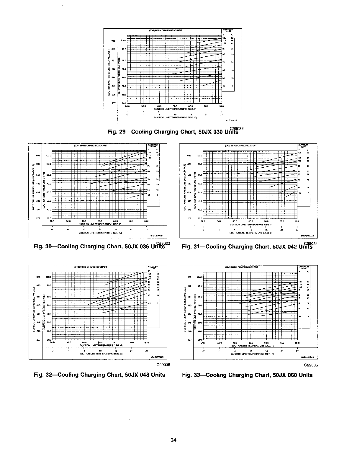
Fig. 29_Cooling Charging Chart, 50JX 030 Un_tl_32
Fig. 30_Cooling Charging Chart, 50JX 036 Un_ 33
s_
II......_)_=_=_=_
,I i ;
c
4 io *_
_x_o_23
C99035
Fig, 32--Cooling Charging Chart, 50JX 048 Units
=
ill _ ............
C99036
Fig. 33_Cooling Charging Chart, 50JX 060 Units
24
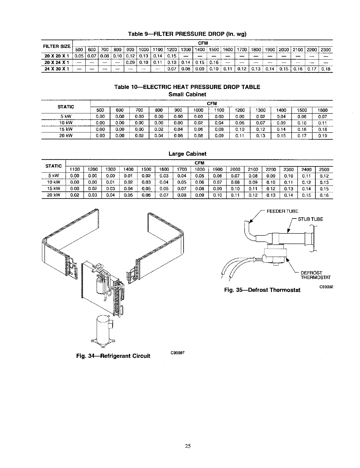
Table 9---FILTER PRESSURE DROP (In. wg)
FILTER SIZE CFM
500 600 700 800 900 1000 1100 1200 1300 1400 1500 1600 1700 1800 1900 2000 2100 2200 2300
20X20X1 0.05 0.07 0.08 0.10 0.12 0.13 0,14 0.15
20 X 24 X 1 0.09 0.10 0.11 0.13 0.14 0.15 0.16
24 X 30 X 1 0,07 0.08 0,09 0,10 0,11 0.12 0,13 0.14 0.15 0.16 0,17 0,18
Table 10_ELECTRIC HEAT PRESSURE DROP TABLE
Small Cabinet
STATIC CFM
500 600 700 800 900 1000 1100 1200 1300 1400 1500 1600
5 kW 0.O0 0.O0 0.00 0.00 0.00 0.00 0.00 0.00 0.02 0.04 0.06 0.07
10 kW 0,00 0.00 0,00 0,00 0,00 0.02 0,04 0,06 0.07 0.09 0.10 0.11
15 kW 0,00 0.00 0,00 0.02 0,04 0,06 0.08 0,10 0.12 0,14 0.16 0,18
20 kW 0.00 0.00 0.02 0.04 0,06 0,08 0,09 0,11 I 0,13 0.15 0.17 0.10
I
STATIC
5 kW
10 kW
15 kW
20 kW
1100 1200 1300 1400 1500
0.00 0.00 0.0O 0.01 0.02
0.00 0,00 0.01 0,02 0.03
0.00 0.02 0.03 0,04 0,05
0.02 0,03 0.04 0,05 0.06
Large Cabinet
CFM
1600 1700 1800 1900 2000 2100 2200 2300 2400 2500
0.03 0.04 0.05 0.06 0.07 0.09 0.09 0.10 0.11 0,12
0.04 0.05 0.06 0.07 0.08 0.09 0.10 0.11 0.12 0.13
0.06 0.07 0.08 0.09 0.10 0.11 0.12 0.13 0.14 0.15
0.07 0.08 0.09 0.10 0.11 0.12 0.13 0.14 0.15 0.16
DEFROST
THERMOSTAT
Fig. 35---Defrost Thermostat C99092
Fig. 34_Refrigerant Circuit C99097
25
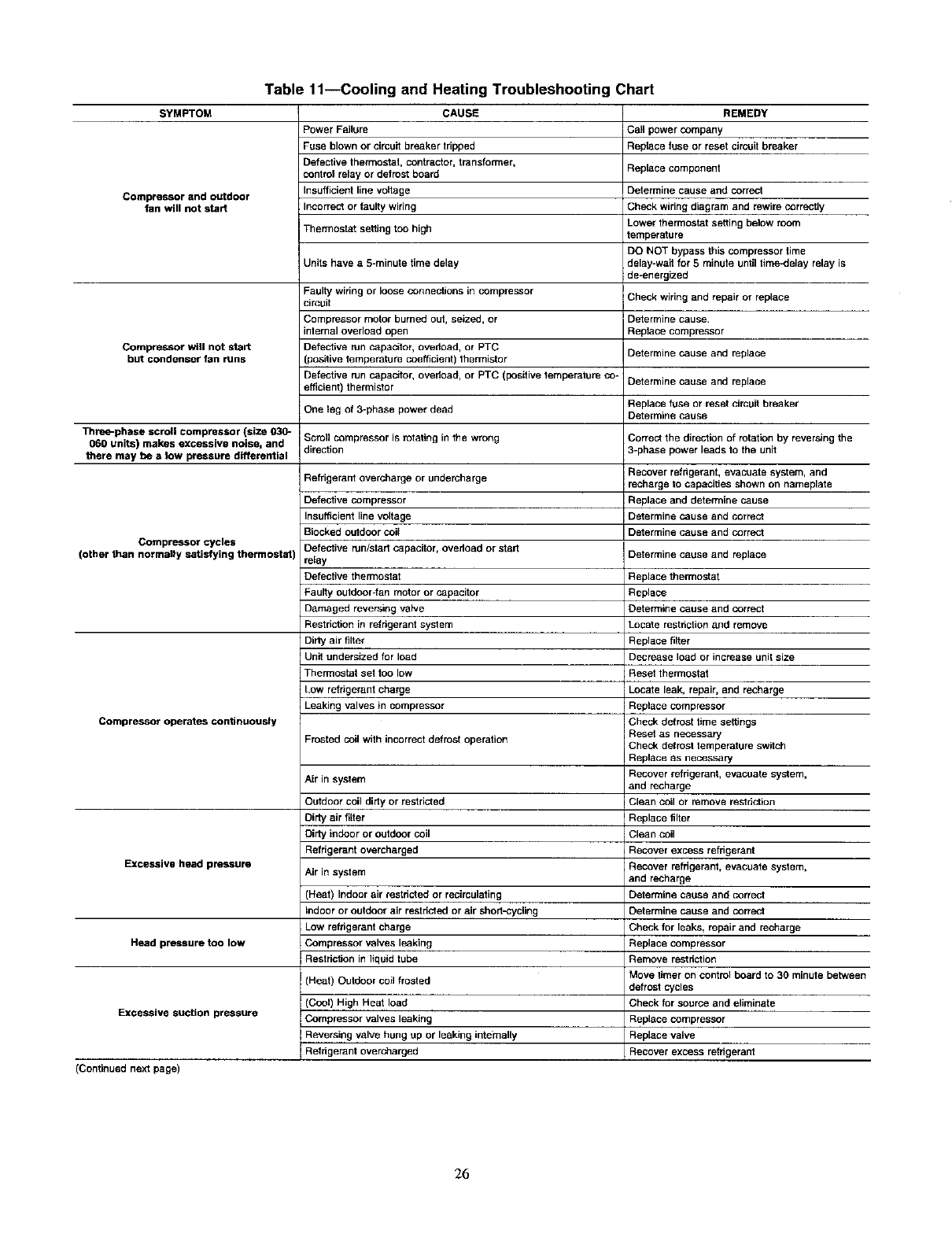
SYMPTOM
Compressor and outdoor
fan will not start
Compressor will not start
but condenser fan runs
Table 11--Cooling and Heating Troubleshooting Chart
CAUSE
Power Failure
Fuse blown or circuit breaker tripped
Defective thermostat, contractor, transformer,
control relay or detrost board
Insufficient line voltage
Incorrect or faulty wiring
Thermostat setting too high
Units have a 5-minute time delay
Faulty wiring or loose connections in compressor
circuit
Compressor motor burned out, seized, or
internal overload open
Defective run capacitor, overfoad, or PTC
(positive temperature coefficient) thermistor
Defective run capacitor, overload, or PTC (positive temperature co-
efficient) thermistor
REMEDY
Call power company
Replace fuse or reset circuit breaker
Replace component
Determine cause and correct
Check wiring diagram and rewire correctly
Lower thermostat setting below room
temperature
DO NOT bypass this compressor time
delay-waft for 5 minute until time,delay relay is
de-energized
Check wiring and repair or replace
Determine cause.
Replace compressor
Determine cause and replace
Determine cause and replace
Replace f,Jse or reset circuit breaker
Determine cause
One leg of 3-phase power dead
Three-phase scroll compressor (size 030- Scrst] compressor is rotating in the wrong Correct the direction of rotation by reversing the
060 units) makes excessive noise, and direction 3-phase power leads to the unit
there may be a low pressure differential
Compressor cycles
(other than normally satisfying thermostat)
Compressor operates continuously
Excessive head pressure
Refrigerant overcharge or undercharge
Dateetive compressor
Insufficient line voltage
Blocked outdoor coft
Defective run/start capacitor, ovedoad or start
relay
Defective thermostat
Faulty outdoor-fan motor or capacitor
Damaged reversing valve
Restriction in refggerant system
Dirty air filter
Unit undersized for load
Thermostat set too low
Low refrigerant charge
Leaking valves in compressor
Frosted coil with incorrect defrost operation
Air in system
Outdoor coil didy or restricted
Dirty air tiger
Dirty indoor or outdoor coil
Refrigerant overcharged
Air in system
(Heat) Indoor air restricte_ or recirculating
indoor or outdoor air restdcted or air short_ycling
Low refrigerant charge
Compressor valves leaking
Restriction in liquid tube
(Heat) Outdoor coft frosted
Compressor valves leaking
Reversing valve hung up or leaking intemafty
Head pressure too low
Excessive suction pressure
(Continued next page)
Recover refrigerant, evacuate system, and
recharge to capacities shown on nameplate
Replace and determine cause
Determine cause and correct
Determine cause and correct
Determine cause and replace
Replace thermostat
Replace
Determine cause and correct
Locate restriction and remove
Replace filter
Decrease load or increase unit size
Reset thermostat
Locate leak, repair, and recharge
Replace compressor
Check defrost time settings
Reset as necessary
Check defrost temperature switch
Replace as necessary
Recover refrigerant, evacuate system,
and recharge
Clean coil or remove restdcgon
Replace filter
Clean coil
Recover excess refrigerant
Recover refrigerant, evacuate system,
and recharge
Determine cause and correct
Determine cause and correct
Check for leaks, repair and recharge
Replace compressor
Remove restriction
Move timer on control board to 30 minute between
defrost cycles
Check for source and eliminate
Replace compressor
Replace valve
Recover excess refrigerant
26
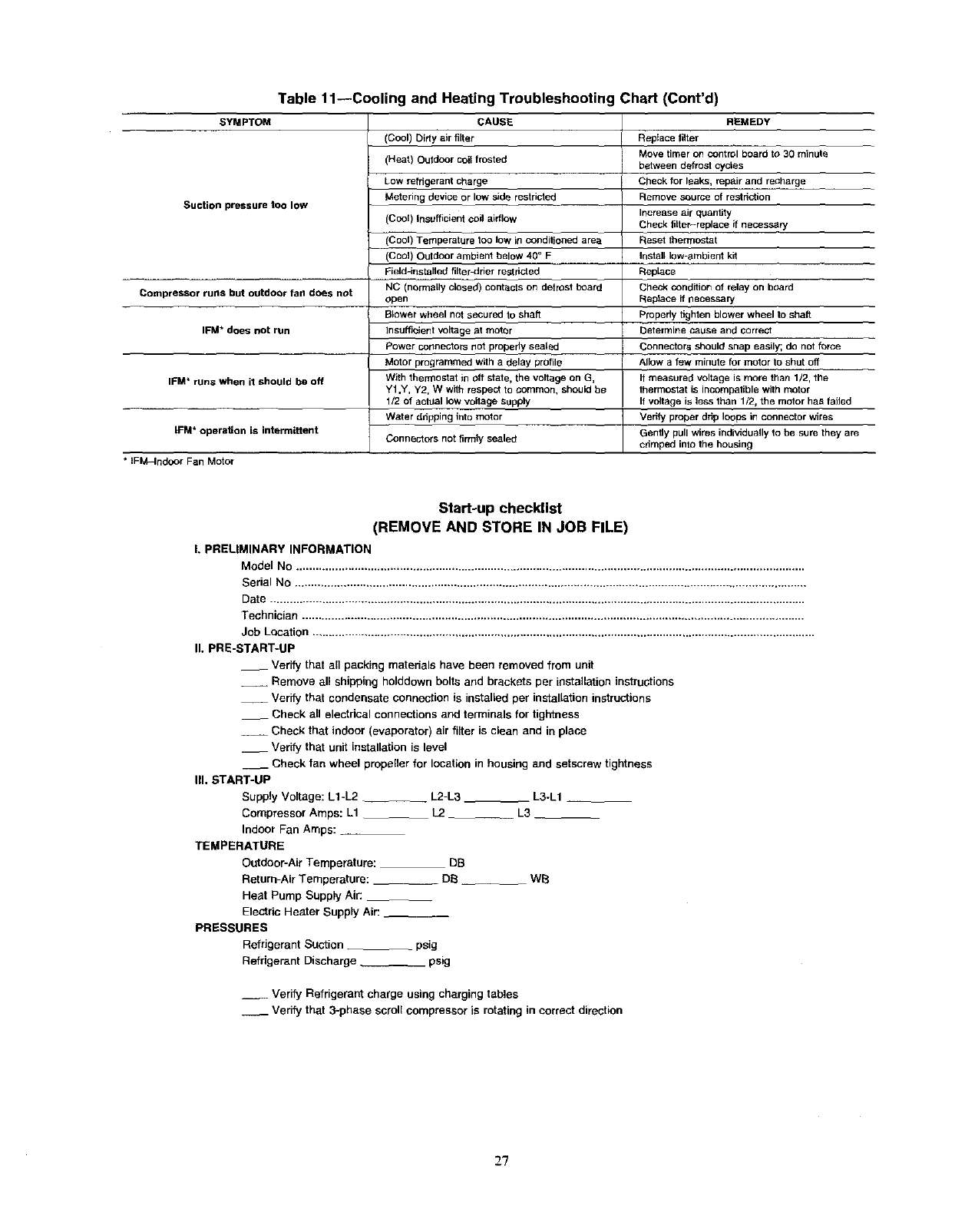
Table 11--Cooling and Heating Troubleshooting Chart (Cont'd)
SYMPTOM CAUSE
Suction pressure too low
Compressor runs but outdoor fan does not
IFM* does not run
IFM* runs when it should be off
IFM* operaSon is intermittent
*IFM4ndoor Fan Motor
(Cool) Dirty air filter
(Heat) Outdoor coil frosted
Low refrigerant charge
Metering device or low side restricted
(Cool) Insufficient coil airflow
(Cool) Temperature too low in conditioned area
(Cool) Outdoor ambient below 40 °F
Field-installed filter-drier restricted
NC (normally closed) contacts on defrost beard
open
Blower wheel not secured to shaft
insufficient voltage at motor
Power connectors not properly sea{ed
Motor programmed with a delay profile
With thermostat in off state, the voltage on G,
Y1,Y, Y2, W with respect to common, should be
1/2 of actual low voltage supply
Water ddpping into motor
Connectors not firmly sealed
REMEDY
RepIace filter
Move timer on control board to 30 minute
between defrost cycles
Check for leaks, repair and reCharge
Remove source of restriction
Increase air quantity
Check filter-replace if necessary
Beset thermostat
Install Iow-_.mbient kit
RepLace
Check condition of relay on board
Replace if necessary
Properly tighten blower wheel to shaft
I_etermine cause and correst
Connectors should snap easily; do not force
Allow a few minute for motor 1o shut off
It measured voltage is more than 1/2, the
thermostat is incompatible with motor
If voltage is less than 1/2, the motor has failed
Verify proper drip loops in connector wires
Gently pull wires individually to be sure they are
crimped into the housing
Start-up checklist
(REMOVE AND STORE IN JOB FILE)
I. PRELIMINARY INFORMATION
Model No .............................................................................................................................................................
Serial No ..............................................................................................................................................................
Date .....................................................................................................................................................................
Technician ...........................................................................................................................................................
Job Location ...........................................................................................................................................................
II. PRE-START-UP
__ Verify that an packing materials have been removed from unit
-- Remove all shipping holddown bolts and brackets per installation instructions
-- Verify that condensate connection is installed per installation instructions
__ Check all electrical connections and terminals for tightness
-- Check that indoor (evaporator) air filter is clean and in place
-- Verify that unit installation is level
-- Check fan wheel propeller for location in housing and setscrew tightness
Ul, START-UP
Supply Voltage: L1-L2 -- L2-L3 -- L3-L1
Compressor Amps: L1 L2 L3
Indoor Fan Amps:
TEMPERATURE
Outdoor-Air Temperature: __ DB
Return-Air Temperature: -- DE} WR
Heat Pump Supply Air:
Electric Heater Supply Air:
PRESSURES
Refrigerant Suction psig
Refdgerant Discharge psig
-- Verify Refrigerant charge using charging tables
-- Verify that 3-phase scroll compressor is rotatingin correct direction
37
Copyright 2006 CARRIER Corp. • 7310 W. Morris St. • Indianapolis, IN 46231
Manufacturer reserves the right to discontinue, or change at any time, specifications or designs without notice and without incurring obligations.
Book 1 4
Tab 6 8 PC 101 Printed in U.S.A. Catalog No. 50JS,JX-6Sl Pg 26 2-0_ Replaces: New
