CHANDLER SYSTEMS EVB019-BLE Legacy View Valve User Manual Michelle Stuart Coy
CHANDLER SYSTEMS, INC. Legacy View Valve Michelle Stuart Coy
User manual

User manual
Model: EVB-019-BLE

pg. 2
12:00
Main Menu
1. To enter Main Menu, press the Menu/Enter button.
(Time of Day will flash)
2. To set the Time of Day, press the Set/Change button.
(First digit will flash) Example [12:00]
- To change digit value, press the Set/Change button.
- To accept the digit value, press the Menu/Enter button.
- Next digit will flash to begin setting.
- Once the last digit display is accepted, all digits will flash.
3. To set A.M. or P.M., press the Menu/Enter button.
- To change digit value, press the Set/Change button. Example [ A ]
- To accept the digit value, press the Menu/Enter button.
- Once A.M. or P.M. is accepted, the next menu item will flash.
4. To set the Number of Days between Regeneration or Backwash Cycles (A), press the
Set/Change button.
- Repeat instructions from step (2). Example [ A - 07 ]
Notes: 1) Maximum value is 29.
2) If value set to 0, Automatic Regeneration will never occur.
3) Default setting is 4 days for softeners and 6 days for filters.
4) On metered models, an “H” will appear to enter Compensated
Hardness in grains per gallon (gpg). Example [ H – 20]
5) Default setting is 25 gpg.
5. To set the Number of Days between Air Draw Cycles (d), press the Set/Change Button
- Repeat instructions from step (2) “Used on Nitro & Nitro Pro Filters Only” Example [ d – 01 ]
Notes: 1) Maximum value is 29.
2) If value set to 0, air draw is turned off, but an air cycle will still be completed when
backwash cycle occurs. If the Number of Days between Air Draw Cycles is set to
a higher number of days than the Number of Days between Backwash Cycles, it
will have no effect. In order to turn off all cycles, both the Days between Backwash
and Days between Air Draw Cycles must be set to 0.
3) Default setting is 1 day.
6. To Exit Main Menu, press the Menu/Enter button.
Note: If no buttons are pressed for 60 seconds, the Main Menu will be exited automatically.
SET
CHANGE
MENU
ENTER
Menu/Enter
Button
Set/Change
Button
pg. 3
Normal Operation
1. Home Display
- Alternates between the display of Time of Day and Number of Days until the Next Regeneration.
- Days Remaining until the Next Regeneration will count down from the entered Regeneration Day
Override Value until it reaches 1 day remaining.
- A Regeneration Cycle will then be initiated at the next designated regeneration time.
- Metered models alternate the Time of Day and Gallons left until the next Regeneration. The meter
will count down to zero (0000) and then regenerate at the scheduled time set.
2. Battery Back-Up (Uses a standard 9-volt alkaline battery.)
- Installing the battery
- Features of Battery Back-Up
Maintains the Time of Day during power failures.
Notes: 1) During power failures, the display is turned off to conserve battery power. However, to confirm that
the battery is working, press either button and the display will turn on for five (5) seconds.
2) If power failure occurs while system is regenerating, the Signature Series II will motor to a shut off
position to prevent constant flow to drain. Note: Depending upon system pressure and other
factors, it is possible to observe a reduced flow to drain during this step. After power is restored,
the Signature Series II will return and finish the cycle where it left off prior to the power interruption.
3) When used without battery back-up, the unit acts like a standard valve. When a power failure
occurs, the unit stops at its current point in the regeneration position and then restarts at that point
when the power is restored. However, the time will be offset by the increment of time the unit was
without power.
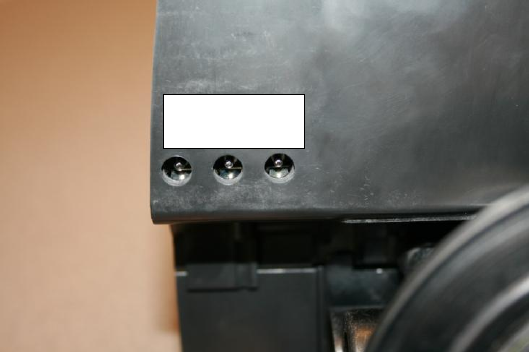
Electronic Connections
P = Power Supply
B = Powered in Backwash Cycle Only
S = Powered in Entire Regeneration
Cycle
P B S
pg. 4
Starting Extra Regeneration Cycle
1. To Start Delayed Extra Cycle Example [ 1 ]
- If Days Remaining Until Next Regeneration does not read „1‟, press and hold the
Set/Change button for 3 seconds until the display reads „1‟, or „0000‟ on metered models.
- Regeneration cycle will initiate at the next designated regeneration time.
2. To start Immediate Extra Cycle First complete above step.
- With Days Remaining Until Next Regeneration at „1‟ or „0000‟,
- Press and hold the Set/Change button.
- After 3 seconds, the regeneration cycle will begin.
3. To Fast Cycle thru regeneration First complete above 2 steps.
Note: Fast Cycle is not necessary unless desired to manually step through each cycle step.
- Press and hold the Set/Change button for 3 seconds to advance to the next cycle step.
Softeners
Default (min.)
Filters
Default
(min.)
Step 1 : Backwash
10
Step 1 : Backwash
10
Step 2 : Brine & Rinse
60
Step 2 : Rest
5
Step 3 : Rapid Rinse
10
Step 3 : Rapid Rinse
10
Step 4 : Brine Refill
Set for full salting
Step 4 : Not Used
0
Nitro
Default (min.)
Nitro Pro
Default
(min.)
Step 1 : Air Release
6
Step 1 : Air Release
6
Step 2 : Backwash
10
*Step 2 : Oxyclean NP Injection
15 sec.
Step 3 : Rest
5
Step 3 : Short Rinse
1
Step 4 : Air Replenish
12
Step 4 : Rest
20
Step 5 : Rapid Rinse
10
Step 5 : Backwash
10
Step 6 : Rest
5
Warning: On NITRO PRO System, if “J”
Program is used, the Oxyclean NP must be
used to avoid any warranty issues.
Step 7 : Air Replenish
12
Step 8 : Rapid Rinse
10
Note: Depending upon system pressure
and other factors, it is possible to observe
flow to drain in the rest cycles.
*Only if “J” program (Oxyclean NP Option) is
activated.
pg. 5
Nitro Only Backwash Cycle Step Explanation
Step 1: Air Release Step
For approximately 6 minutes
- Not programmable
Step 2: Backwash Step
- Default of 10 minutes
Step 3: Rest Step
- Default of 5 minutes
Step 4: Air Replenish Step
- Default of 12 minutes
Example:
4-12
Step 5: Rapid Rinse Step
- Default of 10 minutes
Notes:
- When the valve is between positions, the display will flash the number of the step it is moving towards.
- The default time at which regeneration will occur is 2:00 a.m. for softeners and 12:00 a.m. for filters.
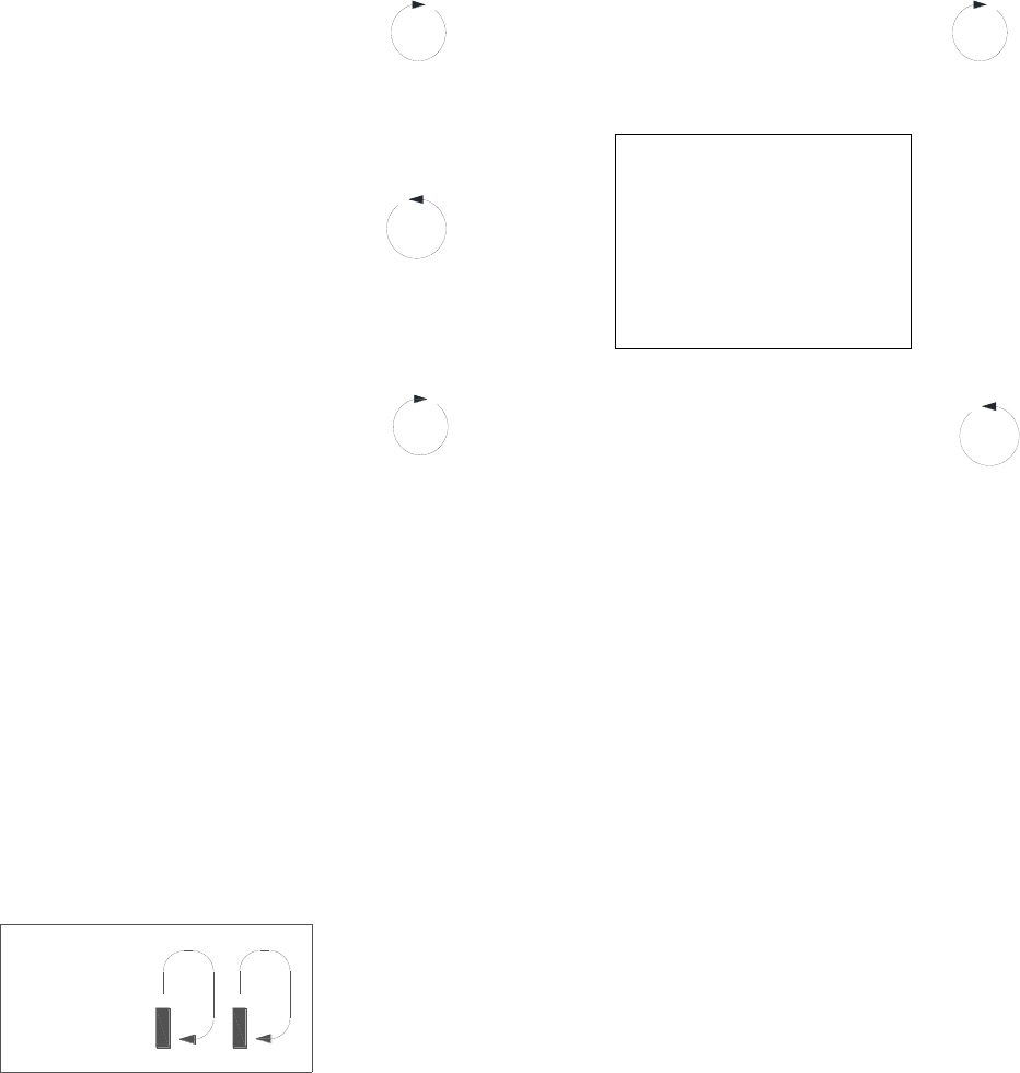
New feature: The motor‟s run direction during a particular regeneration cycle step is indicated by
the rotation direction of the last 2 digit displays.
5-

pg. 6
Nitro Pro Only Backwash Cycle Step Explanations
(With “J” Program Activated – Oxyclean NP Option)
Step 1: Air Release Step
For approximately 6 minutes
- Not programmable
Step 2: Oxyclean NP Injection
For 15 seconds
- Not programmable
Step 3: Short Rinse Step
For 1 minute
- Not programmable
Step 4: Rest Step
For 20 minutes
- Not programmable
Step 5: Backwash Step
- Default of 10 minutes
Step 6: Rest Step
- Default of 5 minutes
Example:
6-05
Step 7: Air Replenish Step
- Default of 12 minutes
Step 8: Rapid Rinse Step
- Default of 10 minutes
Note: Depending upon system pressure and other factors, it is possible to observe flow to drain in the rest
cycles.
Notes:
- When the valve is between positions, the display will flash the number of the step it is moving towards.
- The default time at which regeneration will occur is 2:00 a.m. for softeners and 12:00 a.m. for filters.
New feature: The motor‟s run direction during a particular regeneration cycle step is indicated by
the rotation direction of the last 2 digit displays.
5-

pg. 7
Final Set-Up
With proper valve operation verified (Softeners only):
1. Add water to the top of the air check. Manually step the valve to the Brine Cycle (position 2) and
allow the valve to draw water from the brine tank until it stops. Note: The air check will check at
approximately the midpoint of the screened intake area.
2. Next, manually step the valve to the Brine Refill position and allow the valve to return to Service
automatically.
3. With the valve in Service, check that there is about 3 to 5 inches of water level above the grid in the
brine tank, if used.
4. Fill the brine tank with salt to complete set-up. The control will run automatically.
Error Codes
There are four (4) error codes which could indicate a possible problem with the control valve:
Error 2 - Homing slot expected. Valve will begin searching for home.
(Normal operation continues.)
Error 3 - Encoder is not sending a signal.
(Valve requires service to continue.)
Error 4 - Unable to find homing slot.
(Valve requires service to continue.)
Error 5 - Motor overload (stalled position or shorted motor).
(Valve requires service to continue.)
Error 5 Explanation: The unit thinks the motor is locked. This can only happen when the valve is running
the motor, it is not seeing any encoder slots, and the motor is overloaded. This usually alerts the
presence of foreign debris inside the valve clogging the system.

pg. 8
Master Programming Mode
To enter Master Programming Mode, press and hold both buttons for 5 seconds.
Note: All Master Programming functions have been preset at the factory. Unless a change is desired, it is
NOT necessary to enter Master Programming Mode.
1. Regeneration Type (t) N/A for Nitro / Nitro Pro
- This display is used to set the Regeneration Type. This option setting is identified by the letter “t” in the
left digit. There are two possible settings:
- Timeclock / Filter Delayed – The control will determine that regeneration is required when the set
regeneration time has been reached. The regeneration frequency setting will determine which days a
regeneration cycle will be initiated. Example ( t - - c ).
- Meter Delayed (Demand) – The control will determine that regeneration is required when the available
volume of softened water drops to or below zero. Regeneration is to begin at the scheduled time set.
Example ( t - - d ).
● The Set/Change button will adjust this value. To accept the digit value, press the Menu/Enter
button.
2. Regeneration Day Override (A) – Meter (Demand) Mode Only – Softeners Only
- Press Menu/Enter button. This display is used to set the maximum amount of time (in days) the unit
can be in service without regeneration. This option setting is identified by the letter “A” in the left digit.
Regeneration will begin at the scheduled time. A setting of zero will cancel this feature.
- Example: Override every 7 days (A-07), default setting, or cancel setting (A-00). Maximum is 29.
3. To Set Regeneration Time ( r ) Example [ r 12A ]
- The time of day at which regeneration may take place is designated by the letter “r”.
- The first display digit indicates A.M. or P.M. To change the value, press the Set/Change button.
- Press Menu/Enter button to accept the value and move to the next digit.
- The second and third display digits indicate the hour at which the regeneration will occur.
- Change the digits with the Set/Change button and accept with the Menu/Enter button.
- After the entire display flashes, press the Menu/Enter button to move to the next menu item.
4. To Activate Oxyclean NP Program (Nitro Pro Only)
- “J” program is selectable either off – 0 (default setting) or on – 1.
- To activate the non-adjustable cycles for the Oxyclean NP, select J-1 with the Set/Change button and
enter with the Menu/Enter button.
pg. 9
5. To Set Regeneration Cycle Step Times Softeners/Filters Only (1) (2) (3) (4) Example [ 3 – 20 ]
- The next 4 displays set the duration of time in minutes for each backwash cycle step.
- The step number which is currently modifiable is indicated on the far left of the display screen.
- The number of minutes allotted for the selected backwash step is displayed on the far right.
- Change the digit values using the Set/Change and Menu/Enter buttons as described above.
5. To Set Backwash Cycle Step Times Nitro (2) (3) (4) (5) / Nitro Pro (5) (6) (7) (8) Example [ 3 – 20 ]
- The next 4 displays set the duration of time in minutes for each backwash cycle step.
- The step number which is currently modifiable is indicated on the far left of the display screen.
- The number of minutes allotted for the selected backwash step is displayed on the far right.
- Change the digit values using the Set/Change and Menu/Enter buttons as described above.
Note on Air Draw Cycle (4): Nitro Filter Only (7) Nitro Pro Only
The longer the unit is set to remain in the Air Draw cycle (4), the more air is drawn into the system. A
default setting of 12 minutes draws air down to the level of a normal media bed height and then returns
the unit to the home display. If the system needs more air, increase the time setting for step (4) or
decrease the number of days between air draw cycles. There is no way to view the number of days
until the next air draw will take place.
5. System Capacity in Grains ( c ) – Meter (Demand) Only
- Press the Menu/Enter button. This display is used to set the system capacity in grains and is used in
conjunction with the hardness setting to calculate total gallons of treated water available between
regenerations. This option is identified by the letter “c” in the left digit. The maximum value for this item
is 399. Example: 32,000 grain capacity ( c 032 ).
6. To Exit the Master Programming Mode, press the Menu/Enter button until time of day returns.
Note: If no buttons are pressed for 60 seconds, the Master Programming Mode will be exited automatically.

pg. 10
SET
CHANGE
MENU
ENTER
Master Programming Mode Flow Chart
- To enter Master Programming mode,
Press and hold both buttons for 5 seconds.
→
SET
CHANGE
To change value
REGEN
TYPE
↓
↓
→
MENU
ENTER
To accept value
MENU
ENTER
↓
→
SET
CHANGE
To change value
DAY
OVERRIDE
↓
METER MODE ONLY
↓
→
MENU
ENTER
To accept value
MENU
ENTER
↓
→
SET
CHANGE
To change value
UNIT
CAPACITY
↓
METER MODE ONLY
↓
→
MENU
ENTER
To accept value
MENU
ENTER
↓
→
SET
CHANGE
To change value
REGEN
TIME
↓
↓
→
MENU
ENTER
To accept value
MENU
ENTER
↓
→
SET
CHANGE
To change value
REGEN STEP
1,2,3 & 4
↓
↓
→
MENU
ENTER
To accept value
MENU
ENTER
→
The Program Mode will be exited and
normal operation resumed.

pg. 11
Control Valve Assembly (Nitro & Nitro Pro)

pg. 12
NITRO & NITRO PRO BODY ASSEMBLY

pg. 13
NITRO & NITRO PRO BODY ASSEMBLY
PART No.
DESCRIPTION
Qty.
1
20009X231
PISTON ASSEMBLY
1
2
20001X226
HEX SCREW
3
3
20001X232
SEAL & SPACER KIT
1
4
20251X100
DRAIN LINE FLOW CONTROL HOUSING
1
5
20561X225
BRINE VALVE
1
6
N/A
END SPACER
1
7
20001X214
DRAIN RETAINER CLIP
1
8
20001X228
BRINE LINE FLOW CONTROL ASSY.
1
9
20251X305
BRINE LINE FERRULE
1
10
20251X304
BRINE LINE COMPRESSION NUT
1
11
20009X005
PLUG
1
12
20001X226
HEX SCREW
2
13
20009X001
INJECTOR COVER NITRO PRO
1
14
20001X224
INJECTOR SEAL
1
15
20001X219
INJECTOR ASSEMBLY WHITE (SPECIFY COLOR)
1
16
20001X222
INJECTOR SCREEN
1
17
20001X217
INJECTOR PLUG
1
18
20001X215
TANK O-RING
1
19
20561X204
DISTRIBUTOR PILOT O-RING
1
20
20251X272
DLFC 5.0 BUTTON (SPECIFY SIZE)
1
21
20561X216
ADAPTER O-RING
4
22
20561X201
CLIP
2
23
20561X217
HEX SCREW
2
24
20561X215
ADAPTER COUPLING
1
25
20111X011
ADAPTER COUPLING CHECKVALVE
1
26
N/A
VALVE BODY
1
27
20009X010
INJECTOR CAP PLUG
1
28
GA-T0620666B
3/8" 90 ELBOW
3
29
57005X001
3/8" BLACK TUBING / FT.
0.2
30
GA-S0660416B
STEM ADAPTER
1
31
20009X007
INJECTION ASSEMBLY
1
pg. 14
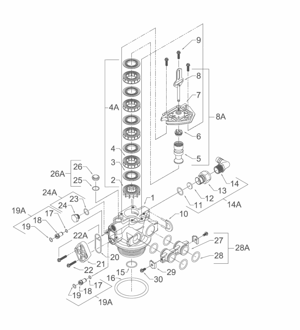
Control Valve Drive Assembly (Filter Version)

pg. 15
Control Valve Drive Assy. (Filter Version)
Ref
#
Description
Part #
Qty.
Ref
#
Description
Part #
Qty.
0
Valve Body Complete
20001X200
1
15
O Ring
20561X204
1
1
Valve Body Only
20001X201
1
16
O Ring
2000X215
1
2
End Spacer
N/S
1
17
O Ring
N/S
1
3
Seal
N/S
5
18
Injector
N/S
1
4
Spacer
N/S
4
19
O Ring
N/S
2
4A
Seal & Spacer Kit
Incl. (1) #2, (5) #3, & (4) #4
20001X232
1
19A
Injector Plug & O Ring Assembly
Incl. (1) each #17 thru #19
20001X217
1
5
Down Flow Piston
N/S
1
20
Injector Seal
20001X224
1
6
Piston End Rod Retainer
N/S
1
21
Injector Cap
20001X223
1
7
End Plug Assembly
N/S
1
22
10-24 X 1 Hex Washer HD Screw
20001X226
2
8
Piston Arm
N/S
1
22A
Filter Conversion Kit
Incl. (1) each #19A, #24A, #26A,
#20, #21 & (2) #22
20001X221
1
8A
Piston Assembly
Incl. (1) each #5 thru #8
20001X231
1
9
Hex Washer HD 10-24 X 13/16” Screw
N/S
3
23
O Ring
N/S
1
10
Drain Retainer
20001X214
1
24
Filter Plug
N/S
1
11
O Ring
20251X254
1
24A
O Ring & Filter Plug Assembly
Incl. (1) each #23 thru #24
20001X229
1
12
Flow Control Button 1.5 GPM
20251X266
1
Flow Control Button 2.0 GPM
20251X267
1
25
O Ring
N/S
1
Flow Control Button 2.4 GPM
20251X268
1
26
Brine Valve Cap
N/S
1
Flow Control Button 3.0 GPM
20251X269
1
26A
O Ring & Brine Valve Cap Assembly
20001X230
1
Flow Control Button 3.5 GPM
20251X270
1
Flow Control Button 4.0 GPM
20251X271
1
Items #27 thru #30 used only with clock regeneration
Flow Control Button 5.0 GPM
20251X272
1
27
Adapter Coupling
N/S
2
Flow Control Button 7.0 GPM
20251X274
1
28
O Ring
20561X216
4
13
Plastic Flow Control Housing
N/S
1
28A
Adapter Coupling & O Ring
Assembly
Incl. (1) # 27 & (2) #28
20561X215
1
14
Drain Line Fitting 90º Elbow
1/2” NPT x 1/2” Tubing
20251X255
1
29
Mounting Clip
20561X201
2
14A
Flow Control Assembly-Specify GPM
Incl. (1) each #11 thru #14
30
8-18 X 5/8” Hex Washer HD Screw
20561X217
2
Flow Control Assy. 1.5 GPM-PVC
20251X256
1
Flow Control Assy. 2.0 GPM-PVC
20251X257
1
N/S indicates non-stocked item
Shaded Ref # indicates assembly or kit
Flow Control Assy. 2.4 GPM-PVC
20251X258
1
Flow Control Assy. 3.0 GPM-PVC
20251X259
1
Flow Control Assy. 3.5 GPM-PVC
20251X260
1
Flow Control Assy. 4.0 GPM-PVC
20251X261
1
Flow Control Assy. 5.0 GPM-PVC
20251X262
1
Flow Control Assy. 7.0 GPM-PVC
20251X264
1
pg. 16
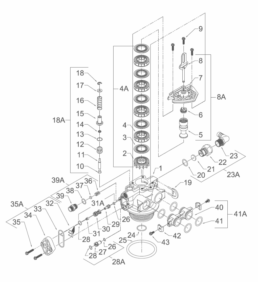
Control Valve Assembly (Softener Version)
pg. 17
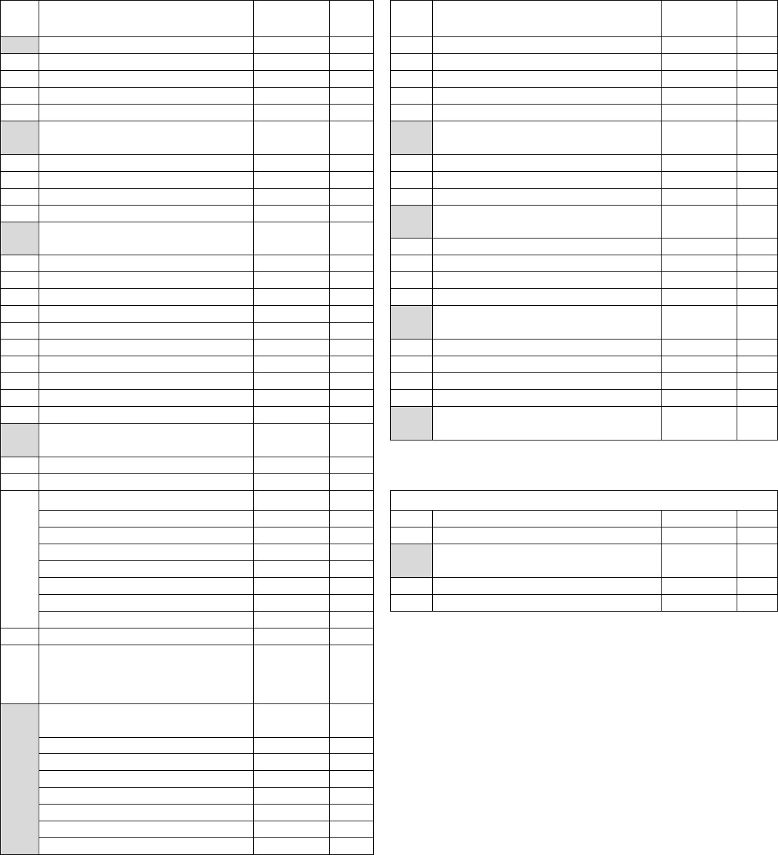
Control Valve Drive Assembly Parts List (Softener Version)
Ref
#
Description
Part #
Qty.
Ref
#
Description
Part #
Qty.
0
Valve Body Complete
20001X200
1
24
O Ring
20561X204
1
1
Valve Body Only
20001X201
1
25
O Ring
20001X215
1
2
End Spacer
N/S
1
26
O Ring
N/S
2
3
Seal
N/S
5
27
Injector Plug
N/S
1
4
Spacer
N/S
4
28
O Ring
N/S
1
4A
Seal & Spacer Kit
Incl. (1) #2, (5) #3 & (4) #4
20001X232
1
28A
Injector Plug & O Ring Assy.
Incl. (1) each #26 thru # 28
20001X217
1
5
Down Flow Piston
N/S
1
29
Injector Throat
N/S
1
6
Piston End Rod Retainer
N/S
1
30
Injector Nozzle
N/S
1
7
End Plug Assembly
N/S
1
31
Vortex Generator
N/S
1
8
Piston Arm
N/S
1
31A
Injector Assy. Specify Size
Incl. (1) each #2 & #28 thru #31
20001X219
1
8A
Piston Assembly
Incl. (1) each #5, #6, #7 & #8
20001X231
1
32
Injector Screen
20001X222
1
9
Hex Washer HD 10-24 X 13/16” Screw
N/S
3
33
Injector Seal
20001X224
1
10
Brine Valve Set
N/S
1
34
Injector Cap
20001X223
1
11
Brine Valve Stem
N/S
1
35
10-24 1 Hex Washer HD Screw
20001X226
2
12
Brine Valve Spacer
N/S
1
35A
Injector Kit – Specify Size –
Incl. (1) ea #31A, #32, #33, #34 & (2) #35
20001X220
1
13
O Ring
N/S
1
14
Quad Ring
N/S
1
36
BLFC Button Retainer
20561X240
1
15
Brine Valve Cap
N/S
1
37
5 GPM BLFC Button
20251X318
1
16
Brine Valve Spring
N/S
1
38
O Ring
20561X239
1
17
Plain Nylon Washer
N/S
1
39
BLFC Adapter
20561X241
1
18
Retaining Ring
N/S
1
39A
BLFC Assembly .5 GPM -
Inc. (1) each #36 thru #39
20001X228
1
18A
Brine Assembly
Incl. (1) each #10 thru #18
20001X210
1
19
Drain Retainer
20001X214
1
20
O Ring
20251X254
21
Flow Control Button 1.5 GPM
20251X266
1
Items #40 thru #43 used ONLY with clock regeneration
Flow Control Button 2.0 GPM
20251X267
1
40
Adapter Coupling
N/S
2
Flow Control Button 2.4 GPM
20251X268
1
41
O Ring
20561X216
4
Flow Control Button 3.0 GPM
20251X269
1
41A
Adapter Coupling & O Ring Assy.
Incl. (1) #40 & (2) # 41
20561X215
1
Flow Control Button 3.5 GPM
20251X270
1
Flow Control Button 4.0 GPM
20251X271
1
42
Mounting Clip
20561X201
2
Flow Control Button 5.0 GPM
20251X272
1
43
8-18 X 5/8” Hex Washer HD Screw
20561X217
2
Flow Control Button 7.0 GPM
20251X274
1
22
Plastic Flow Control Housing
N/S
1
23
Drain Line Fitting 90º Elbow
1/2" NPT X 1/2" Tubing
20251X255
1
N/S indicates non-stocked item
shaded Ref # indicates assembly
or kit
23A
Flow Control Housing – Specify GPM
Incl. (1) each #20 thru #23
Flow Control Assy. 1.5 GPM-PVC
20251X256
1
Flow Control Assy. 2.0 GPM-PVC
20251X257
1
Flow Control Assy. 2.4 GPM-PVC
20251X258
1
Flow Control Assy. 3.0 GPM-PVC
20251X259
1
Flow Control Assy. 3.5 GPM-PVC
20251X260
1
Flow Control Assy. 5.0 GPM-PVC
20251X262
1
Flow Control Assy. 7.0 GPM-PVC
20251X264
1
pg. 18
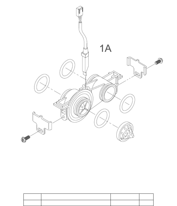
Meter Assembly
Meter Assembly Parts List
Ref #
Description
Part #
Qty.
1A
Meter Assembly, Turbine Complete
20564X200
1
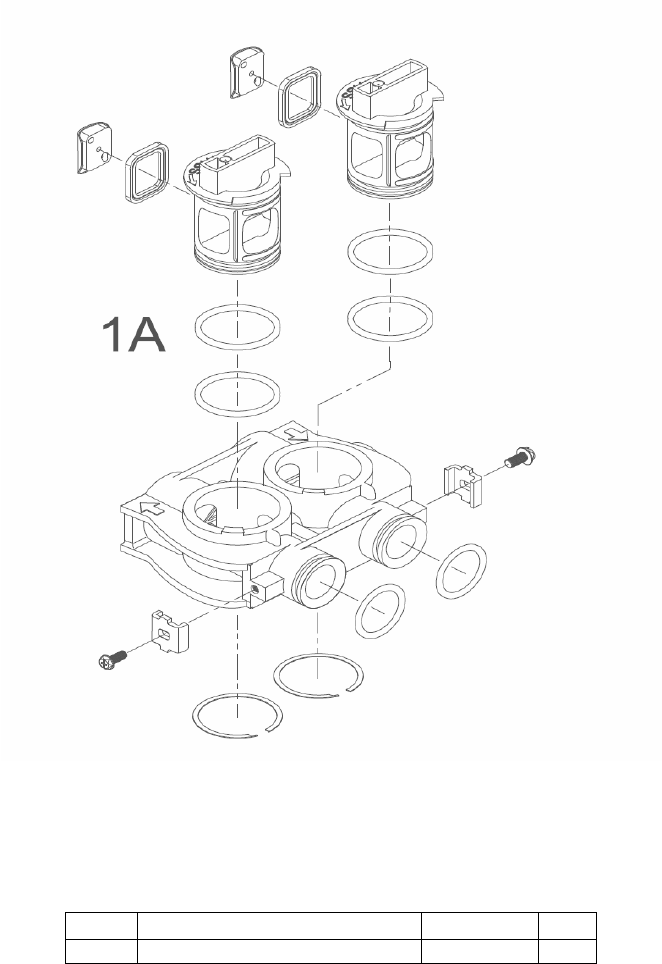
pg. 19
Bypass Assembly (Plastic)
Ref #
Description
Part #
Qty.
1
Plastic Bypass Valve Assembly
20561X292
1
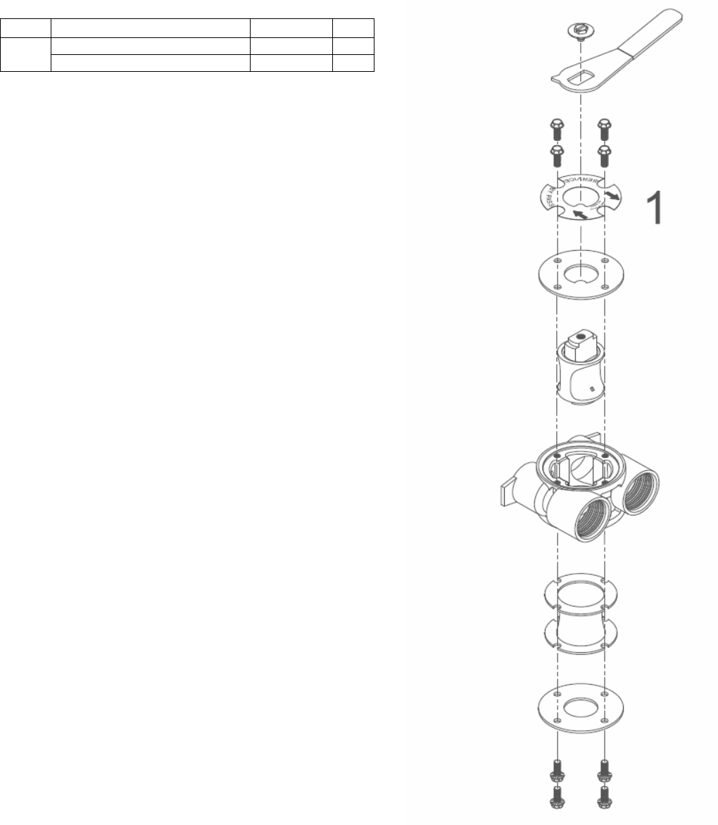
pg. 20
Bypass Assembly
(Stainless Steel)
Ref #
Description
Part #
Qty.
1
Bypass Valve 3/4" Stainless Steel
20561X270
1
Bypass Valve 1” Stainless Steel
20561X283
1

pg. 21
Service Instructions
A. General Preliminary Instructions – PERFORM BEFORE ALL SERVICING OPERATIONS!
1. Turn off water supply to conditioner.
If the conditioner installation has a “three valve” bypass system, first open the valve in the bypass line, then
close the valves at the conditioner inlet and outlet.
If the conditioner has an integral bypass valve, put it in the bypass position.
If there is only a shut off valve near the conditioner inlet, close it.
2. Relieve water pressure in the conditioner by stepping the control into the backwash position momentarily. Return
the control to the service position.
3. Unplug electrical cord from outlet.
4. Disconnect brine tube and drain line connections at the injector body.
B. To Replace Brine Valve (need first A1-A3)
1. Remove the control valve back cover. Disconnect
the meter signal wire from the meter.
2. Remove screw and washer at drive yoke. Remove
powerhead mounting screws. The entire
powerhead assembly will now lift off easily.
3. Remove piston retaining plate screws and pull
upward on end of piston yoke until assembly is out
of valve.
4. Pull brine valve from injector body, also remove
and discard O ring at bottom of brine valve hole.
5. Apply silicone lubricant to O ring and reinstall at
bottom of brine valve hole.
6. Apply silicone lubricant to O ring on new brine
valve assembly and press into brine valve hole,
shoulder on bushing should be flush with injector
body.
7. Insert screws through injector cap and into mating
holes in the valve body. Tighten screws.
8. Reconnect brine tube and drain line.
9. Return bypass or inlet valving to normal service
position. Water pressure should now be applied to
the conditioner, and any bypass line shut off.
10. Check for leaks at all seal areas. Check drain seal
with the control in the backwash position.
11. Plug electrical cord into outlet.
12. Set time of day and cycle control valve manually to
assure proper function. Make sure control valve is
returned to the service position.
13. Make sure there is enough salt in the brine tank.
14. Start regeneration cycle manually if water is hard.
C. To Replace Injectors & Screen (need first A1 & A3)
1. Remove injector cap screws, remove cap and
discard gasket. Remove vortex generator from end
of the injector assembly.
2. Remove injector assembly. Apply silicone lubricant
to new injector assembly O rings and install. Be
sure to push injector assembly tightly so O rings
are seated. Replace vortex generator. Install a new
screen.
3. Apply silicone lubricant to new gasket and install
around oval extension on injector cap.
4. Repeat B7-B14.
D. To Replace Powerhead
1. Remove the control valve back cover. Remove the
three screws along the outer edge of the back plate
and remove the front cover. Disconnect the power
supply and the circuit board signal wire from the
motor and feed them back through the control.
Disconnect the optical sensor signal wire.
Disconnect the meter signal wire from circuit board
and feed back through the control.
2. Remove screw and washer at drive yoke. Remove
powerhead mounting screws. The entire
powerhead assembly will now lift off easily.
3. Put new powerhead on top of the valve. Be sure
the drive pin on main gear engages slot in drive
yoke (wide side of drive yoke upright must face to
the left away from the motor).
4. Replace powerhead mounting screws. Replace
screw and washer at drive yoke.
5. Reconnect meter signal, optical sensor, power
supply, and circuit board signal wires.
6. Reinstall front cover and back cover.

pg. 22
E. To Replace Piston Assembly
1. Follow steps A.1 through A.3.
2. Remove control valve back cover. Disconnect the
meter signal wire from the meter.
3. Remove screw and washer at drive yoke. Remove
powerhead mounting screws. The entire
powerhead assembly will now lift off easily.
4. Remove piston retaining plate screws.
5. Pull upward on end of piston yoke until assembly is
out of valve.
6. Inspect the inside of the valve to make sure that all
spacers and seals are in place, and that there is no
foreign matter that would interfere with the valve
operation.
7. Take new piston assembly as furnished and push
piston into valve by means of the end plug. Twist
drive yoke carefully in a clockwise direction to
properly align it with drive gear. Reinstall piston
retaining plate screws.
8. Place powerhead on top of valve. Be sure drive pin
on main gear engages slot in drive yoke (wide side
of drive yoke upright must face to the left away
from the motor).
9. Replace powerhead mounting screws. Replace
screw and washer at drive yoke.
10. Reconnect brine tube and drain line.
11. Return bypass or inlet valving to normal service
position. Water pressure should now be applied to
the conditioner, and any bypass line shut off.
12. Replace the control valve back cover.
13. Follow steps A.9 through A.13.
F. To Replace Seals and Spacers
1. Follow steps A.1 through A.3.
2. Remove the control valve back cover. Disconnect
the meter signal wire from the meter.
3. Remove screw and washer at drive yoke. Remove
powerhead mounting screws. The entire
powerhead assembly will now lift off easily.
Remove piston retaining plate screws.
4. Pull upward on end of piston rod yoke until
assembly is out of valve. Remove and replace
seals and spacers.
5. Take piston assembly and push piston into valve
be means of the end plug. Twist drive yoke
carefully in a clockwise direction to properly align it
with drive gear. Reinstall piston retaining plate
screws. (Same as E7 – E9?)
6. Place powerhead on top of valve. Be sure drive pin
on main gear engages slot in drive yoke (wide side
of drive yoke upright must face to the left away
from the motor).
7. Replace powerhead mounting screws. Replace
screw and washer at drive yoke.
8. Return bypass or inlet valving to normal service
position. Water pressure should now be applied to
the conditioner, and ay bypass line shut off.
9. Replace the control valve back cover. (Same as
E11 – E13?)
10. Follow steps A.9 through A.13.
G. To Replace Meter
1. Follow steps A.1 through A.3.
2. Remove two screws and clips at bypass valve or
yoke. Pull resin tank away from plumbing
connections.
3. Remove signal wire from meter.
4. Remove two screws and clips at meter and pull the
meter out of the control valve.
5. Apply silicone lubricant to four new O rings and
assemble to four ports on new meter.
6. Assemble meter to control valve. Note: meter
portion of module must be assembled at valve
outlet. Install two screws and clips.
7. Install signal wire into new meter.
8. Push resin tank back to the plumbing connections
and engage meter ports with bypass valve or yoke.
9. Attach two clips and screws at bypass valve or
yoke. Be sure clip legs are firmly engage with lugs.
10. Return bypass or inlet valving to normal service
position. Water pressure should now be applied to
the conditioner, and any bypass line shut off.
11. Check for leaks at all seal areas.
12. Follow steps A.9 through A.13.
H. To Check Drive Motor Operation
1. Remove the control valve back cover.
2. To verify drive motor operation, push service button
located on back of motor. Motor should run.
Release button. After 1 minute, the control should
automatically advance to Rapid Rinse (cycle #4)
position. It will remain in Rapid Rinse for 5 minutes
and then advance to Service position.

pg. 23
Troubleshooting Guide
SYMPTOM
PROBABLE CAUSE
CORRECTION
1.
Softener fails to
regenerate
automatically
Power supply plugged into intermittent or
dead power source
Connect to constant power source
Disconnected meter cable
Reconnect cable
Improper control valve programming
Reset program settings
Defective power supply
Replace power supply
Defective circuit board or meter
Replace or repair
Defective drive motor
Check motor operation by activating
the service button on back of motor
2.
Regeneration at
wrong time
Time of day improperly set, due to power
failure
Reset time of day programming and
install 9-volt battery
Regeneration time set improperly
Reset regeneration time programming
3.
Loss of capacity
Increase raw water hardness
Reset unit to the new capacity
Brine concentration and/or quantity
Keep brine tank full of salt at all times.
Clean it yearly. Salt may be bridged.
If using a salt grid plate, ensure refill
water is over it.
Resin fouling
Call dealer. Find out how to confirm it.
Clean the resin and prevent future
fouling.
Poor distribution, channeling (uneven bed
surface)
Call dealer. Check distributors and
backwash flow.
Internal valve leak
Call dealer. Replace spacers, seals
and/or piston.
Resin age
Call dealer. Check for resin oxidation
caused by chlorine. Mushy resin.
Resin loss
Call dealer. Check for correct bed
depth. Broken distributors. Air or gas
in bed: well gas eliminator. Loose
brine line.
4.
Poor water quality
Check items listed in #1, #2, & #3
Bypass valve open
Close bypass valve.
Channeling
Check for too slow or high service
flow. Check for media fouling.

pg. 24
SYMPTOMS
PROBABLE CAUSE
CORRECTION
5.
High salt usage
High salt setting
Adjust brine tank refill time
Excessive water in brine tank
See symptom # 7.
Constant flow through the unit
Indicates plumbing leak (i.e. toilet
tank)
Improperly set hardness
Reset programming
6.
Loss of water
pressure
Scaling / fouling of inlet pipe
Clean or replace pipeline.
Pretreat to prevent.
Fouled resin
Clean resin. Pretreat to prevent.
Improper backwash
Too many resin fines and/or sediment.
Call dealer. Reset backwash flow rate,
and/or adjust.
7.
Excessive water in
brine tank and/or
salty water to
service
Plugged drain line
Check flow to drain. Clean flow
control.
Dirty or damaged brine valve
Clean or replace brine valve.
Plugged injector
Clean injector and replace screen.
Low inlet pressure
Increase pressure to allow injector to
perform properly. (20 psig minimum)
Excessive brine refill cycle time
Reset brine refill cycle time.
8.
Softener fails to
use salt
Check items listed in #1
Improper control valve programming
Check and reset programming
Plugged/restricted drain line
Clean drain line and/or flow control
Injector is plugged
Clean or replace injector and screen
No water in brine tank
Check for restriction in BLFC. Ensure
safety float is not stuck. Check brine
tank for leaks.
Water pressure is too low
Line pressure must be at least 20 psi.
Brine line injects air during brine draw
Check brine line for air leaks
Internal control leak
Call dealer. Check piston, seals and
spacers for scratches and dents.
9.
Control cycles
continuously
Faulty circuit board
Replace circuit board.
10.
Continuous flow to
drain
Foreign material in control
Call dealer. Clean valve, rebuild unit.
Internal control leak
Same as above.
Valve jammed in backwash, brine or rapid
rinse position
Same as above.
Motor stopped or jammed.
Replace motor.
pg. 25
FCC Caution.
This device complies with part 15 of the FCC Rules. Operation is subject to the following two conditions: (1) This device may
not cause harmful interference, and (2) this device must accept any interference received, including interference that may
cause undesired operation.
Any Changes or modifications not expressly approved by the party responsible for compliance could void the user's
authority to operate the equipment.
Note: This equipment has been tested and found to comply with the limits for a Class B digital device, pursuant to part 15 of
the FCC Rules. These limits are designed to provide reasonable protection against harmful interference in a residential
installation. This equipment generates uses and can radiate radio frequency energy and, if not installed and used in
accordance with the instructions, may cause harmful interference to radio communications. However, there is no guarantee
that interference will not occur in a particular installation. If this equipment does cause harmful interference to radio or
television reception, which can be determined by turning the equipment off and on, the user is encouraged to try to correct
the interference by one or more of the following measures:
-Reorient or relocate the receiving antenna.
-Increase the separation between the equipment and receiver.
-Connect the equipment into an outlet on a circuit different from that to which the receiver is connected.
-Consult the dealer or an experienced radio/TV technician for help.