COMMAX DRC500LCRF MAIN ENTRANCE CAMERA WITH 13.56MHz RFID User Manual DRC 481L DRC 500L
COMMAX Co., Ltd. MAIN ENTRANCE CAMERA WITH 13.56MHz RFID DRC 481L DRC 500L
COMMAX >
USERS MANUAL
-Feature-
•8-wire Common Method (Interphone)
•4-wire Common Method (Videophone)
•RF/ID Feature (Optional)
•Surveillance Monitor Support
Model No. DRC-481L(C)/RF
DRC-500L(C)/RF
DRC-481L DRC-500L
(Common Method)
Main Entrance Camera
Thank you for purchasing our C OMMAX product.
Please carefully read this UserÕs G uide (in particular, precautions for safety)
before using the product and follow the instructions to use your productexactly.
The company is not respons ible for any safety accidents caused in abnormal
operation of the product.
DRC-481L/DRC-500L-영 문 2006.10.26 1:23 PM 페이지2

NOTE: This equipment has been tested and found to comply with the limits for a Class B
digital device, pursuant to part 15 of the FCC Rules. These limits are designed to provide
reasonable protection against harmful interference in a residential installation.
This equipment generates, uses and can radiate radio frequency energy and, if not installed
and used in accordance with the instructions, may cause harmful interference to
radio communications. However, there is no guarantee that interference will not occur in a
particular installation. If this equipment does cause harmful interference to radio or
television reception, which can be determined by turning the equipment off and on, the
user is encouraged to try to correct the interference by one or more of the following
measures:
-Reorient or relocate the receiving antenna.
-Increase the se paration between the equipment and receiver.
-Connect the equipment into an outlet on a circuit different from that to which the receiver
is connected.
-Consult the dealer or an experienced radio/TV technician for help.
Changes or modifications not expressly approved by the manufacturer responsible
[ CAUTION ]
for compliance could void the user's
authority to operate the equipment.
[FCC compliance Information]
This device complies with part 15 of FCC Rules.
Operation is subject to the following two conditions:
1. This device may not cause harmful interference, and
2. This device must accept any interference received.
Including interference that may cause undesired operation.
[FCC WARNING]
This equipment may generate or use radio frequency energy. Changes or modifications to this
equipment may cause harmful interference unless the modifications are expressly approved in
the instruction manual. The user could lose the authority to operate this equipment if an unauthorized
change or modification is made.
Class B device

- 1 -
Table of Contents
1. Greetings …………………………………………………………………………… 4
2. Before Getting Started …………………………………………………………… 4
3. Overview …………………………………………………………………………… 5
4. PIN Types ………………………………………………………………………… 10
5. Setting PIN ………………………………………………………………………… 11
6.Household PIN Confirmation ……………………………………………………… 14
7.Configuring Building and Serial Numbers in the Main Entrance Interphone ……… 15
8. Using Remote Cardkeys (RF/ID) - Optional ……………………………………… 17
9. Surveillance Monitor Configuration ……………………………………………… 23
10. Door Release Time Setup ………………………………………………………… 24
11. Page Tone Selection ……………………………………………………………… 25
12. Wiring Method Selection ………………………………………………………… 26
13. Video Out Impedance Adjustment ……………………………………………… 27
14. Household Interphone Diagnosis ………………………………………………… 28
15. Household Number Registration ………………………………………………… 30
16. Paging the Household …………………………………………………………… 32
17. Paging the Guardhouse …………………………………………………………… 32
18. Door Release Using the Household PIN ………………………………………… 33
19. Door Release Using the Building (Management) PIN …………………………… 33
20. Appendix (Various Program Summaries) ……………………………………… 34
21. Wiring Method …………………………………………………………………… 36
22. Specifications …………………………………………………………………… 51
- 2 -
Please follow the things described below in order to prevent any
danger or property damage.
Warning
Caution
Safety Warning & Caution
Prohibition.
No disassembly
No touch
Must follow strictly.
Shows plugging out the power cord
without an exception
Shows the warning and caution for an electric shock.
Shows the warning and caution for a fire.
It may cause a serious damage or
injury if violated.
It may cause a minor damage or
injury if violated.
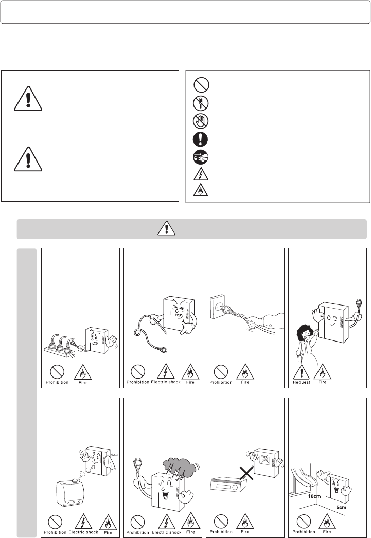
Power & Installation
Warning
Please don’t use several
products at the same time on
one power socket.
·It may cause a fire due to an
abnormal overheating.
Please don’t bend the power
cable excessively or it may
cause an electric shock.
·fire when using a damaged
power cable.
Please don’t handle the power
cable with a wet hand.
·It may cause an electric
shock.
Please plug out the power
cable from the socket when
not using it for a long period
of time.
·It may shorten the product
lifespan or cause a fire.
Please don’t install the
product in the place where
there is much oil, smoke or
humidity.
·It may cause an electric
shock or fire.
Please don’t install the
product with the lightening
and thunder.
·It may cause an electric
shock or fire.
Please don’t use and connect
this product with other
products with different rated
voltage
·It may cause a disorder or
fire.
When installing the product
that generates heat, please
install the product away from
the wall (10cm) for the
ventilation.
·It may cause a fire due to
the increased internal
temperature.
DRC-481L/DRC-500L-영 문 2006.10.26 1:23 PM 페이지2
- 3 -
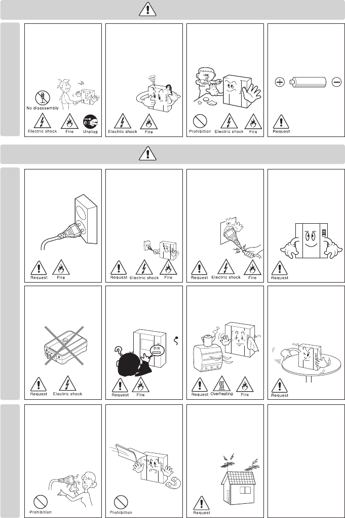
Cleaning & Use
Please don’t disassemble,
repair or rebuild this product
arbitrarily (please contact the
service center if a repair is
needed.
·It may cause an electric
shock or fire.
Please plug the power cable
firmly into the inner end
·It may cause a fire.
Please hold the plug tightly
when unplugging the power
cable (a part of the copper
wire may be disconnected if
the grabbing is only made on
the cord when pulling out the
cable).
·It may cause an electric
shock or fire
When connecting the power
cables after cutting the cable,
please install the product with
power off
·It may cause an electric
shock or fire
When installing the product,
please fix it firmly while using
the wall-mounting unit and
screws.
·It may cause an injury from
the falling object.
Please be careful when using
an AC circuit breaker since
there is a possibility of an
electric shock.
When cleaning the product,
please rub it with a soft and
dry cloth after plugging out
the power cable. (Please don’t
use any chemical products
such as wax, benzene, alcohol
or cleanser.)
Please don’t drop the product
on the ground and don’t apply
a shock .
·It may cause a failure.
Please use the designated
connection cable within the
maximum calling distance
designated for the product
·It may reduce the product
performance.
Please check the use voltage
and current for the DC-only
products and use the
appropriate rectifier.
·It may cause a fire.
Please avoid direct rays of the
sun or heating devices at a
time of installation.
·It may cause a fire.
Please don’t install the
product on an unstable place
or small support board.
·It may cause an injury if it
falls down while in use.
If an abnormal sound, burning
smell or smoke is coming out
of the product, please plug out
the power cable and contact a
service center.
·It may cause an electric
shock or fire.
Please don’t insert any
metallic or burnable materials
into the ventilation hole.
·It may cause an electric
shock or fire.
Please use only the designated
batteries for the products of
using DC power.
·It may cause an electric
shock or fire.
Cleaning & UsePower & Installation
Warning
Caution
DRC-481L/DRC-500L-영 문 2006.10.26 1:23 PM 페이지3

- 4 -
Thank you for purchasing a Commax product.
This product is a high tech Main Entrance interphone that supports
electronic and remote (Optional) keys and finger print recognition
(Optional) features. Please read this manual carefully.
Using 8-wire common wiring method between the Main Entrance interphone and
the Guardhouse interphone, this system supports 3 communication circuits, and
each communication circuit is a Balance Type that supports 2 wires.
Using 4-wire common wiring method between the Main Entrance interphone and
the Household interphone, this system supports telephone and video
connections. Only use coaxial cables for video connection.
The short and cut of wiring can cause a malfunction. Be sure to check wiring
before installation.
It is recommended that each Main Entrance interphone is installed and its
connection be checked from the Guardhouse and the Household(s).
Maximum of 2048 Remote Cardkeys are supported. (When not connected to a
computer)
Three consecutive entries of wrong Management PIN, Building PIN, or
Household PIN will automatically page the Guardhouse.
Three consecutive attempts at unlocking doors with an unregistered Remote
Cardkey will also automatically page the Guardhouse.
1. Greetings
2. Before Getting Started
※Remarks
DRC-481L/DRC-500L-영 문 2006.10.26 1:23 PM 페이지4
- 5 -
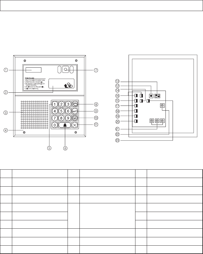
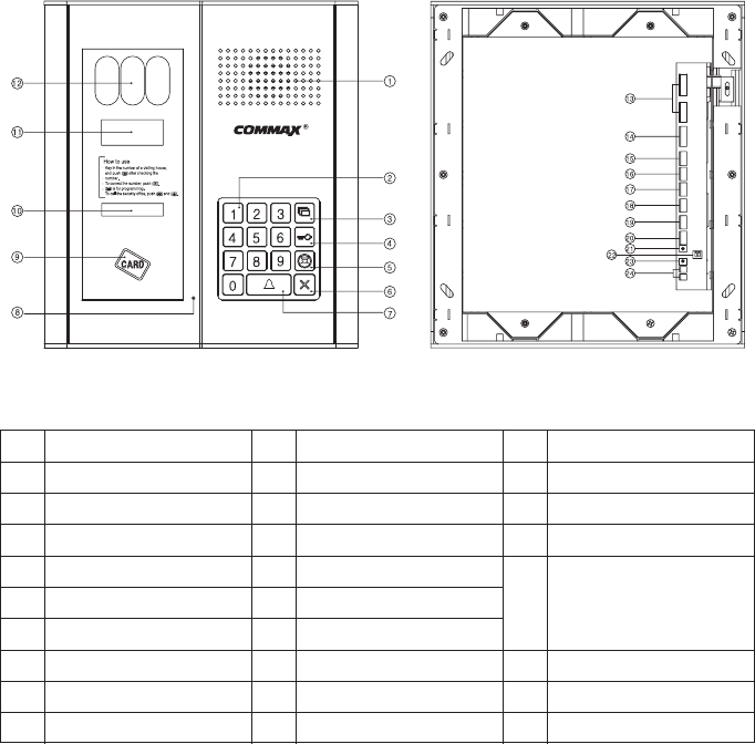
3. Overview
3-1. Feature
DRC-481L
No
1
2
3
4
5
6
7
8
9
Description
Display Window (FND)
RF/ID Receiver (Optional)
Speaker
Mic
Key Pad
Call Button
CCD Camera
Program Button
Electronic Key Button
No
10
11
12
13
14
15
16
Description
Guard Button
Cancel Button
Reset Button
Selection Switches
Infrared Sensor Terminal
Guardhouse Interphone Terminal
Computer Connection Terminal
No
17
18
19
20
21
22
23
Description
Household Interphone (1)
Household Interphone (2)
Video Out
Power: DC12V/1A (RF-1A)
Door Release Terminal
Receiver Volume Control
Security Switch Connection
No. 1: Computer Connection
No. 2: Electronic Key Selection
(Finger Print Recognition)
DRC-481L/DRC-500L-영 문 2006.10.26 1:23 PM 페이지5
- 6 -
DRC-500L
No
1
2
3
4
5
6
7
8
9
Description
Speaker
Key Pad
Program Button
Electronic Key Button
Guard Button
Cancel Button
Call Button
Mic
RF/ID Receiver (Optional)
No
10
11
12
13
14
15
16
17
18
Description
Night Lamp
Display Window (FND)
CCD Camera
Computer Connection Termina
Guardhouse Interphone Termina
Household Interphone (1)
Household Interphone (2)
Video Out(Surveillance Monitor Connection)
Infrared Sensor Terminal
No
19
20
21
22
23
24
Description
Security Switch Connection
Power:
DC15V/1A(CS-15C)
Reset Button
Selection Switches
Receiver Volume Control
Door Release Terminal
No. 1: Computer Connection
No. 2: Electronic Key Selection
- 7 -
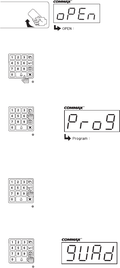
3-2. Basic Function
RF/ID Receiver (Optional)
To open the door using a Remote Cardkey, place the key here. The word ‘oPEn’will
display and the door will be released.
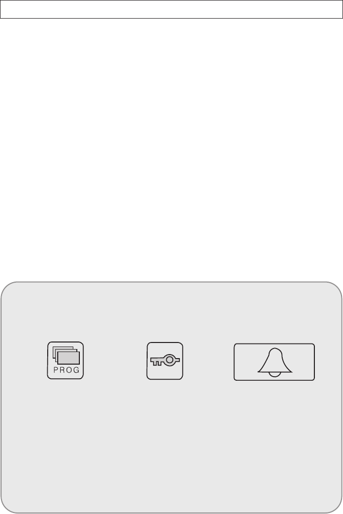
Call Button (E: Enter)
This button is used to page households.
Program Button (P: Program )
This button is used to Program.
Electronic Key Button (K: Key)
This button is used to release the door by using PIN.
(Available only when the Electronic Key option has been set as OFF. When it is set as
ON, Finger Print Recognition is enabled)
Guardhouse Page Button (G: Guard)
This button is used to page the Guardhouse if the Guardhouse interphone has been
installed.
AAuuddiioo GGuuiiddee
““DDoooorr OOppeenneedd””
PPrreessss tthhee PPaaggee bbuuttttoonn aafftteerr eenntteerriinngg
tthhee HHoouusseehhoolldd NNuummbbeerr..
Please the Card Here OPEN DOOR
Program Enter
DRC-481L/DRC-500L-영 문 2006.10.26 1:23 PM 페이지7
- 8 -
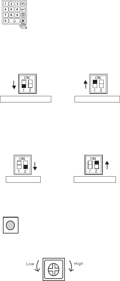
Cancel Button (X: Cancel)
This button is used to cancel the current operation.
Selection Switches
No. 1: Computer Connection Switch (Used for connection with a computer)
Connects a computer using network exclusive to DRC-481L.
OFF : To connect to a computer via the RS-485 Port with Finger Print Recognition in use.
ON : To connect to a computer via an internal network without Finger Print Recognition in
No. 2: Electronic Key Selection (Finger Print Recognition Switch)
OFF: Electronic Key is enabled.
(Finger Print Recognition is disabled)
ON: Electronic Key is disabled.
(Finger Print Recognition is enabled)
Reset Button
This button is used to reset the Guardhouse PIN or the Management PIN.
Receiver Volume Control
Controls the volume in the receiver from LOW to HIGH.
AAuuddiioo GGuuiiddee
““CCaanncceelllleedd””
Not Connecting to a Computer
Using Electronic key
If you cannot remember the number of a management office,
push the reset button both 12 and 21.
Not Using Electronic key
Connecting to a Computer
To Lower the Volume To Raise the Volume
DRC-481L/DRC-500L-영 문 2006.10.26 1:23 PM 페이지8
- 9 -
●Must Know Before Use!
1) Accessing All Features with the Program Button
-When an error has been made as indicated by continuous beeps, please
cancel and start again from the beginning.
2) Forgotten PIN
2-1. Household PIN
Use the Household PIN verification feature of 6-1 to retrieve the PIN.
(Please inquire to the Guardhouse or the Management Office)
2-2. Building PIN
Reenter using the Management PIN.
2-3. Management PIN
Press the Reset button.
Both the Building and the Management Building PINs are reset to default.
3) 8-5 All Remote Cardkey Deletion is to be used only when the unit is being
initially installed.
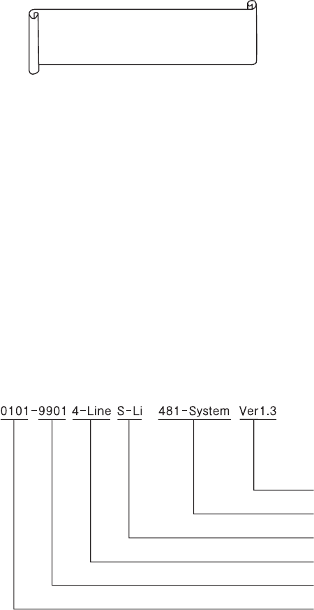
4) Configuration Mode Indications
Configured features are displayed on the Display Window when the Main
Entrance interphone is not in use.
Version No.
Series
Camera Impedance
Wiring Method
Serial Number
Building Number
Beep-Beep-Beep
(Error)
Start again from
the beginning
DRC-481L/DRC-500L-영 문 2006.10.26 1:23 PM 페이지9
- 10 -
4. PIN Types
4-1. Management PIN
- This PIN is for use by the person in charge of the Management Office.
- By default, this PIN is set as 4321.
- For convenience, hereafter management PIN.
4-2. Building PIN
- This is the common PIN for each main entrance.
- By default, this PIN is set as 1234.
- For convenience, hereafter building PIN.
4-2. Household PIN
- Each household has its own PIN.
- By default, this PIN is set as 1234.
- For convenience, hereafter household PIN.
<Reference>
Old PIN
Default Management PIN: 4321
Default Building PIN: 1234
Default Household PIN: 1234
New PIN
New PIN to be set by the user.
P : Program K : Electronic Key E : Call
DRC-481L/DRC-500L-영 문 2006.10.26 1:23 PM 페이지10
- 11 -
5. Setting PIN
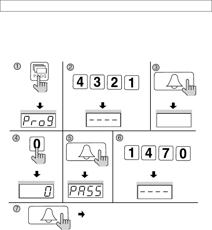
5-1. Management PIN Setup
P - Old Management PIN - E - 0 - E - New PIN -E
Management PIN must be 4-digits long.
0000 will not be recognized as a valid PIN.
①Press the Program button (P). (‘Prog’will appear)
②Enter the old PIN 4321.
③Press the Call button (E).
④Press the Program Number 0.
⑤Press the Call button (E). (‘PASS’will blink)
⑥Enter the new PIN.
⑦Press the Call button (E).
⑧Management PIN has been updated.
Press the Program button (P). Enter the old PIN 4321. Press the
Call button (E).
Press the Program Number 0. Press the
Call button (E).
Press the Call button (E).
Management PIN has been updated.
Enter the new PIN. ex)1470
DRC-481L/DRC-500L-영 문 2006.10.26 1:23 PM 페이지11
- 12 -
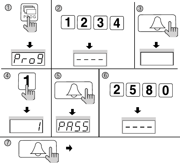
5-2. Building PIN Setup
P - Old Building PIN - E - 1 - E - New PIN - E
Building PIN must be 4-digits long.
0000 will not be recognized as a valid PIN.
①Press the Program button (P). (‘Prog’will appear)
②Enter the old PIN 1234.
③Press the Call button (E).
④Press the Program Number 1..
⑤Press the Call button (E). (‘PASS’will blink)
⑥Enter the new PIN.
⑦Press the Call button (E).
⑧Building PIN has been updated
Press the Program button (P). Enter the old PIN 1234. Press the
Call button (E).
Press the Program Number (1). Press the
Call button (E).
Press the Call button (E).
Building PIN has been updated.
Enter the new PIN. ex)2580
DRC-481L/DRC-500L-영 문 2006.10.26 1:23 PM 페이지12
- 13 -
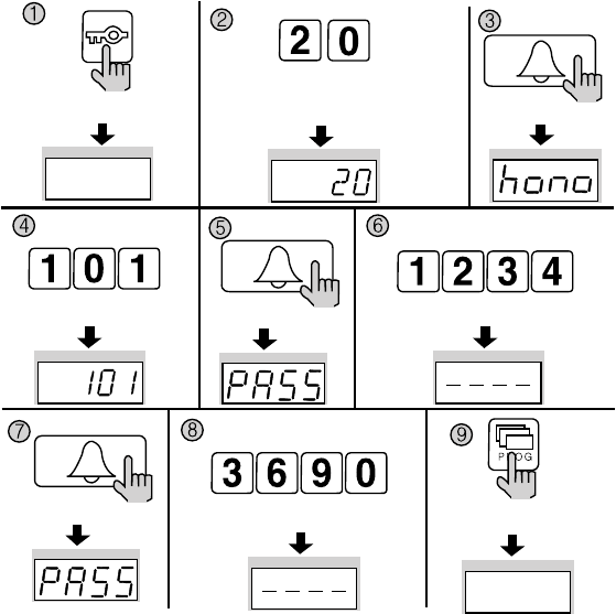
5-3. Household PIN Setup
K - Program Number - E - Household Number - E - Old Household PIN - E - New PIN - P
Household PIN must be 4-digits long.
0000 will not be recognized as a valid PIN.
This method of Household PIN change may vary depending on household interphone types.
(Types that support PIN changing from the household interphone)
①Press the Electronic Key button (K).
②Press the Program Number 20.
③Press the Call button (E). (‘hono’will blink)
④Enter the Household Number.
⑤Press the Call button (E). (‘PASS’will blink)
⑥Enter the old Household PIN.
⑦Press the Call button (E). (‘PASS’will blink)
⑧Enter the new Household PIN
⑨Press the Program button (P).
Household PIN has been updated.
Press the Program button (P).
Press the
Call button (E).
Electronic Key button (K). Press the Program Number (20).
Enter the old PIN. ex)1234
Enter the new Household PIN.
ex)3690
Household Number. ex) 101 Press the
Call button (E).
Press the
Call button (E).
DRC-481L/DRC-500L-영 문 2006.10.26 1:23 PM 페이지13
- 14 -
6.Household PIN Confirmation
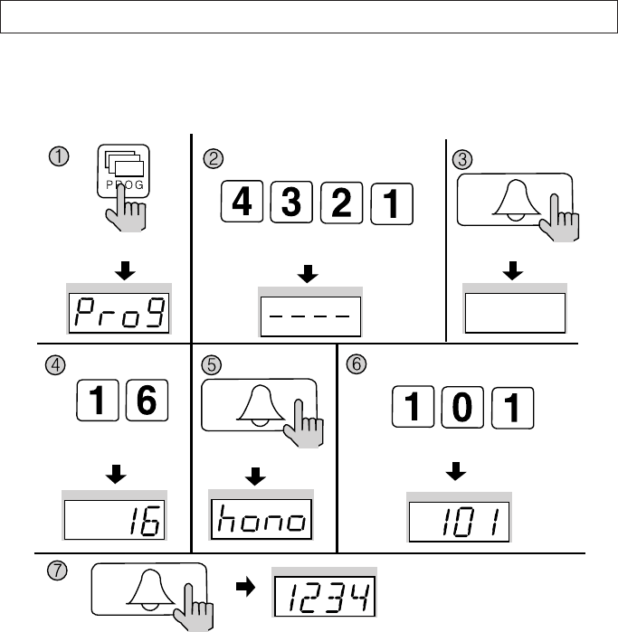
6-1. Household PIN Confirmation
P - Building (Management) PIN - E - Program Number - E - Household Number - E
①Press the Program button. (‘Prog’will appear)
②Enter the Building (Management) PIN.
③Press the Call button (E).
④Press the Program Number (16).
⑤Press the Call button (E). (‘hono’will blink)
⑥Enter the Household Number. (The Household Number will be indicated)
⑦Press the Call button (E). (The Household PIN will be indicated)
Press the Program button (P). Enter the Building (Management) PIN. Press the
Call button (E).
Press the
Program Number (16). Press the
Call button (E).
Press the Call button (E).
ex)1 2 3 4 for household 101
Household Number. ex) 101
DRC-481L/DRC-500L-영 문 2006.10.26 1:23 PM 페이지14
- 15 -
7.
Configuring Building and Serial Numbers in the Main Entrance Interphone
This feature must be performed for it automatically configures Building and Serial
numbers when Households or the Guardhouse is paged from the Main Entrance.
Up to 99 Main Entrance interphones can be installed per each building.
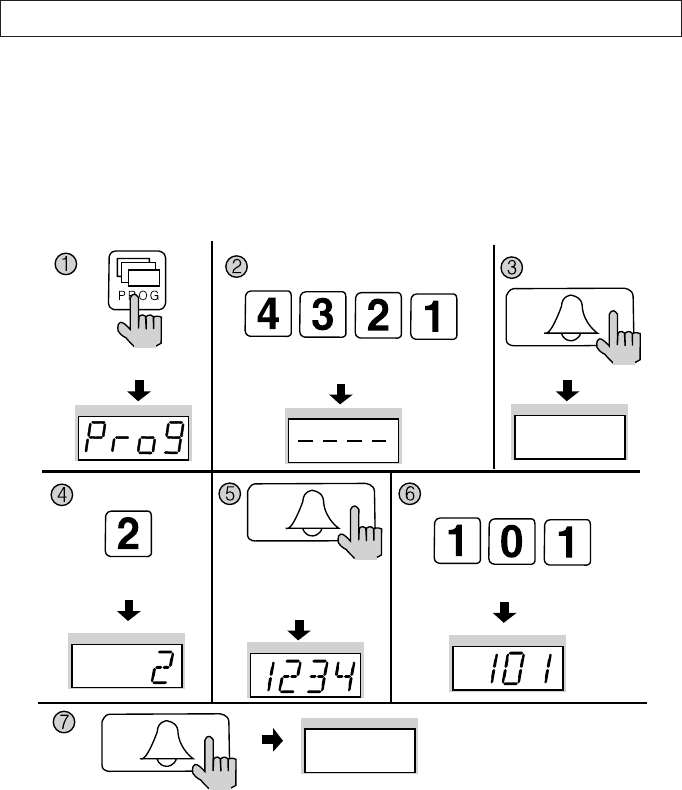
7-1. Configuring Building Number from the Main Entrance Interphone
P - Building (Management) PIN - E - 2 - E - Building Number - E
①Press the Program button (P). (‘Prog’will appear)
②Enter the Building (Management) PIN.
③Press the Call button (E).
④Press the Program Number (2).
⑤Press the Call button (E). (The Building Number previously entered will be indicated)
⑥Enter the new Building Number.
⑦Press the Call button.
Building Number has been updated.
Press the Program button (P). Enter the Building (Management) PIN. Press the
Call button (E).
Press the
Program Number (2).
Press the
Call button (E).
The Building Number previously
entered will be indicated
ex) 1234 Building
Press the Call button (E).
Building Number has
been updated.
Enter the New Building Number
DRC-481L/DRC-500L-영 문 2006.10.26 1:23 PM 페이지15
- 16 -
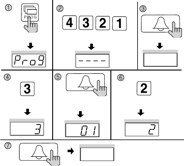
7-2. Configuring Serial Number from the Main Entrance Interphone
P - Building (Management) PIN - E - 3 - E - Serial Number - E
①Press the Program button (P). (‘Prog’will appear)
②Enter the Building (Management) PIN.
③Press the Call button (E).
④Press the Program Number (3) .
⑤Press the Call button (E). (The Serial Number previously entered will be indicated)
⑥Enter the new Serial Number.
⑦Press the Call button
Serial Number has been updated.
Press the Program button (P). Enter the Building (Management) PIN. Press the
Call button (E).
Press the
Program Number (3).
Press the
Call button (E).
The Serial Number previously
entered will be indicated
Press the Call button (E).
Serial Number has been
updated.
Enter the New Serial Number ex) No. 2
DRC-481L/DRC-500L-영 문 2006.10.26 1:23 PM 페이지16
- 17 -
8. Using Remote Cardkeys (RF/ID) - Optional
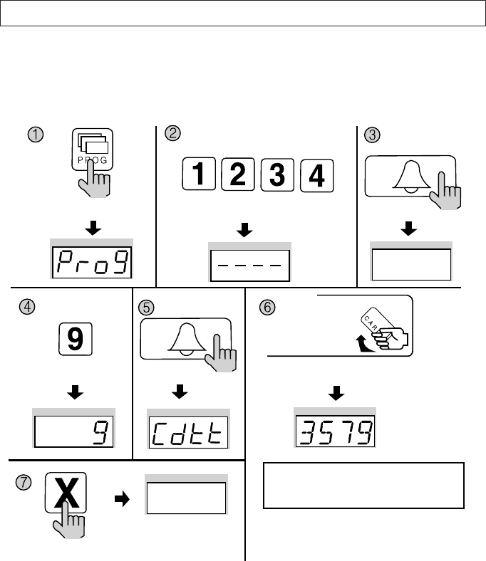
8-1. Testing Remote Cardkeys
P - Building (Management) PIN - E - 9 - E - Card Test - X (Cancel)
This feature is used to test Remote Cardkeys.
①Press the Program button (P). (‘Prog’will appear)
②Enter the Building (Management) PIN.
③Press the Call button (E).
④Press number 9 (Remote Cardkey Test).
⑤Press the Call button. (‘Cdtt’will blink)
⑥Place the Remote Cardkey to the RF/ID Receptor, and the Card Number will appear on
the Display Window (FND).
⑦Press the Cancel button (X) to end Remote Cardkey testing.
Press the Program button (P). Enter the Building (Management) PIN. Press the
Call button (E).
Press the
Program Number (9).
Press the
Call button (E).
Press the Cancel button
(X) to end Remote
Cardkey testing
Press the Card Here
ex) Card Number 3579
Place the Remote Cardkey to the RF/ID
Receptor, and the Card Number will appear on
the Display Window (FND).
To confirm others cardkey, place continuedly the
Remote Cardkey to the RF/ID Recepter
DRC-481L/DRC-500L-영 문 2006.10.26 1:23 PM 페이지17
- 18 -
8-2. Remote Cardkey Registration
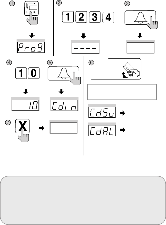
P - Building (Management) PIN - E - 10 - E - Card Registration - X (Cancel)
<Note>
CdSv: Newly Registered Card (Successful registration is indicated by a beep)
CdAl: Previously Registered Card (Rejected registration is indicated by two beeps)
Up to 2048 Remote Cardkeys can be registered. (Without a computer connected)
Please record registered Remote Cardkey’s serial number for future reference.
Press the Program button (P). Enter the Building (Management) PIN.
ex) Building PIN
Press the
Call button (E).
Press the
Program Number (10).
Press the
Call button (E).
Press the Cancel button
(X) to end Remote
Cardkey testing
To confirm others cardkey, place continuedly the
Remote Cardkey to the RF/ID Recepter
Newly
Registered Card
Previously
Registered Card
Press the Card Here
Place the Remote Cardkey to the RF/ID
Receptor, and ‘Cdsv’ or ‘CdAL’ will appear
DRC-481L/DRC-500L-영 문 2006.10.26 1:23 PM 페이지18
- 19 -
8-3. Individual Deletion of Remote Cardkeys
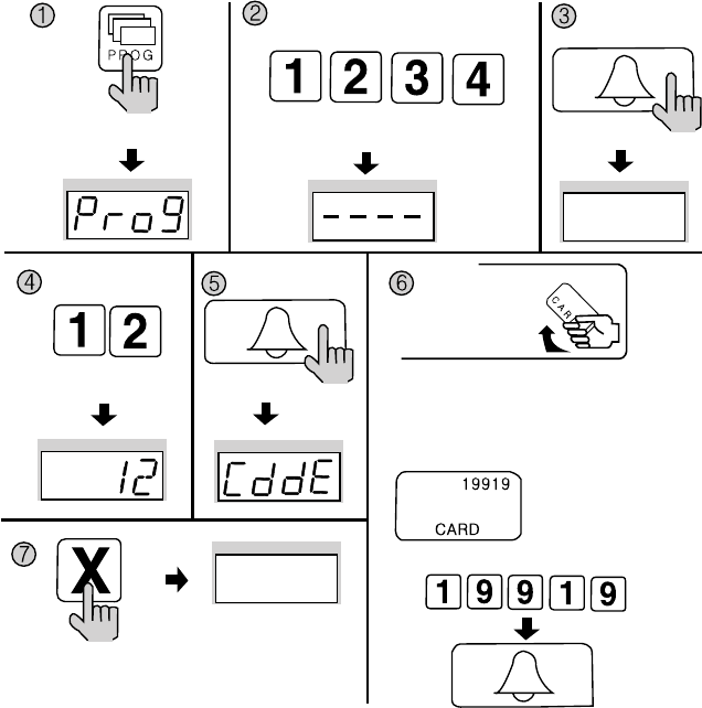
P - Building (Management) PIN - E - 12 - E - Card Deletion - X (Cancel)
①Press the Program button (P). (‘Prog’will appear)
②Enter the Building (Management) PIN.
③Press the Call button (E).
④Press number 12 (Individual Remote Cardkey Deletion).
⑤Press the Call button (E). (‘CddE’will blink)
⑥Enter the 5-digit Card Number and press the Call button (E).
(Check on the right side of the RF/ID Card)
Or place the Card on top of the RF/ID Receiver.
⑦Press the Cancel button (X) to terminate the feature
Press the Program button (P). Enter the Building (Management) PIN.
ex) Building PIN
Press the
Call button (E).
Press the
Program Number (12).
Press the
Call button (E).
Press the Cancel button
(X) to terminate the
feature
Press the Card Here
1. Place the Card on top of the RF/ID Receiver, and
will delete Card Number
2. Enter Card Number and press Call button, and will
delete Card Number
ex) Card Number
19919
ex) For Card Number 19919 delete
DRC-481L/DRC-500L-영 문 2006.10.26 1:23 PM 페이지19
- 20 -
8-4. Confirming Remote Cardkey Registration
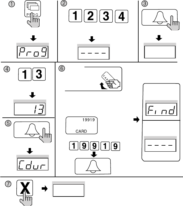
P - Building (Management) PIN - E - 13 - E - Card Confirmation - X (Cancel)
①Press the Program button (P). (‘Prog’will appear)
②Enter the Building (Management) PIN.
③Press the Call button (E).
④Enter number 13 (Remote Cardkey Confirmation).
⑤Press the Call button (E). (‘CddE’will blink)
⑥Enter the 5-digit Card Number and press the Call button (E).
(Check the right side of the RF/ID Card)
Or place the Card on top of the RF/ID Receiver.
⑥Press the Cancel button (X) to terminate the feature.
Press the Program button (P). Enter the Building (Management) PIN.
ex) Building PIN
Press the
Call button (E).
Press the
Call button (E).
Press the
Program Number (13).
Press the Cancel button (X) to terminate
the feature
Press the Card Here
1. Place the Card on top of the RF/ID Receiver,
and will confirm.
2. Enter Card Number and press Call button,
and will confirm Remote Cardkey Registration.
ex) Card Number
19919
Confirm Card
No
Confirm Card
ex) For Card Number 19919 Confirm
DRC-481L/DRC-500L-영 문 2006.10.26 1:23 PM 페이지20
- 21 -
8-5. All Remote Cardkey deletion
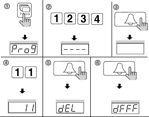
P - Building (Management) PIN - E - 11 - E - E
Refrain from deleting all Remote Cardkeys, except for during installation.
①Press the Program button (P). (‘Prog’will appear)
②Enter the Building (Management) PIN.
③Press the Call button (E).
④Enter number 11 (All Remote Cardkey Delete Number).
⑤Press the Call button (E). (‘dEL’will blink)
⑥Press the Call button (E) again.
The number displayed on screen will change.
⑦Press the Cancel button (X) to terminate the feature.
Press the Program button (P). Enter the Building (Management) PIN.
ex) Building PIN
Press the
Call button (E).
Press the
Call button (E).
All Remote Cardkey mode All Remote Cardkey mode
Press the
Call button (E).
Press the
Program Number (11).
DRC-481L/DRC-500L-영 문 2006.10.26 1:23 PM 페이지21
- 22 -
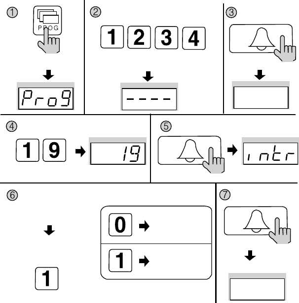
8-6. Remote Cardkey Capacity Expansion
P - Building (Management) PIN - E - 19 - E - 0 - E: Maximum 2048 Cards can be
registered.
P - Building (Management) PIN - E - 10 - E - 1 - E: Unlimited number of Cards can be
registered. (This feature is only available when connected to a computer)
①Press the Program button (P). (‘Prog’will appear)
②Enter the Building (Management) PIN.
③Press the Call button (E).
④Enter number 19 (Remote Cardkey Capacity Change).
⑤Press the Call button (E). (The current capacity is displayed)
⑥Select the Card capacity.
(0: Maximum 2048)
(1: Unlimited)
⑦Press the Call button (E). (Updated)
Press the Program button (P). Enter the Building (Management) PIN.
ex) Building PIN
Press the
Call button (E).
The current capacity
is displayed.
Press the
Call button (E).
Press the
Call button (E).
Press the Program Number (19).
Select the Card capacity.
Maximum 2048
Unlimited Updated
ex) Unlimited
DRC-481L/DRC-500L-영 문 2006.10.26 1:23 PM 페이지22
- 23 -
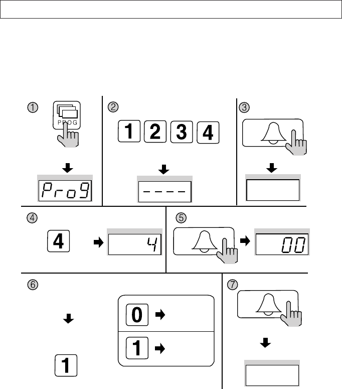
9. Surveillance Monitor Configuration
P - Building (Management) PIN - E - 4 - E - 0 - E: Surveillance disabled.
P - Building (Management) PIN - E - 4 - E - 1 - E: Surveillance enabled.
This feature provides entrance surveillance of the Main Entrance to a separate
monitor by using the Camera from the Main Entrance Interphone.
①Press the Program button (P). (‘Prog’will appear)
②Enter the Building (Management) PIN.
③Press the Call button (E).
④Press number 4 (Surveillance Monitor Configuration).
⑤Press the Call button (E). (Previous selection is displayed)
⑥Choose a mode.
(0: Surveillance monitor cannot be installed)
(1: Surveillance monitor can be installed)
⑦Press the Call button (E). (Modification updated)
Press the Program button (P). Enter the Building (Management) PIN.
ex) Building PIN
Press the
Call button (E).
Press the
Call button (E).
Press the
Call button (E).
Press the Program Number (4).
Choose a mode
ex) Surveillance Configurated
Modification updated
Surveillance
monitor cannot
be installed
Previous selection
is displayed
Surveillance
monitor can be
installed
DRC-481L/DRC-500L-영 문 2006.10.26 1:23 PM 페이지23
- 24 -
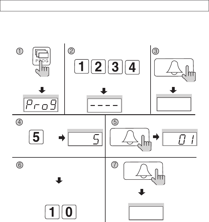
10. Door Release Time Setup
P - Building (Management) PIN - E - 5 - E - Door Release Time - E
This feature adjusts the door release time.
①Press the Program button (P). (‘Prog’will appear)
②Enter the Building (Management) PIN.
③Press the Call button (E).
④Press number 5 (Door Release Time Setup).
⑤Press the Call button (E). (Previous selection is displayed)
⑥Choose a time. (From 1 to 25 seconds)
Use numbers from 1 to 25.
⑦Press the Call button (E). (Modification updated)
Press the Program button (P). Enter the Building (Management) PIN.
ex) Building PIN Press the
Call button (E).
The current capacity
is displayed.
Press the
Call button (E).
Press the
Call button (E).
Press the Program Number (5).
Choose a time.
Use numbers from 1 to 25.
Modification updated
ex) Door Release time
Selected 10 seconds
DRC-481L/DRC-500L-영 문 2006.10.26 1:23 PM 페이지24
- 25 -
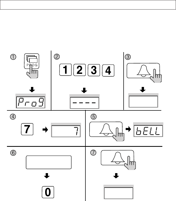
11. Page Tone Selection
P - Building (Management) PIN - E - 7 - E - 0 - E: Melody Tone
P - Building (Management) PIN - E - 7 - E - 1 - E: Bell (Ringer)
This feature sets the Recall tone heard when Households or the Guardhouse is
paged from the Main Entrance.
①Press the Program button (P). (‘Prog’will appear)
②Enter the Building (Management) PIN.
③Press the Call button (E).
④Press number 7 (Page Signal Selection).
⑤Press the Call button (E). (Previous selection is displayed)
⑥Select a page signal.
0: Melody Tone
1: Bell (Ringer)
⑦Press the Call button (E). (Page signal updated)
Press the Program button (P). Enter the Building (Management) PIN.
ex) Building PIN Press the
Call button (E).
The current capacity
is displayed.
Press the
Call button (E).
Press the
Call button (E).
Press the Program Number (7).
Selection a Page Signal
0: Melody Tone
1: BELL Tone(RINGER)
Page signal updated
ex) Selection a Page Signal selected melody tone
DRC-481L/DRC-500L-영 문 2006.10.26 1:23 PM 페이지25
- 26 -
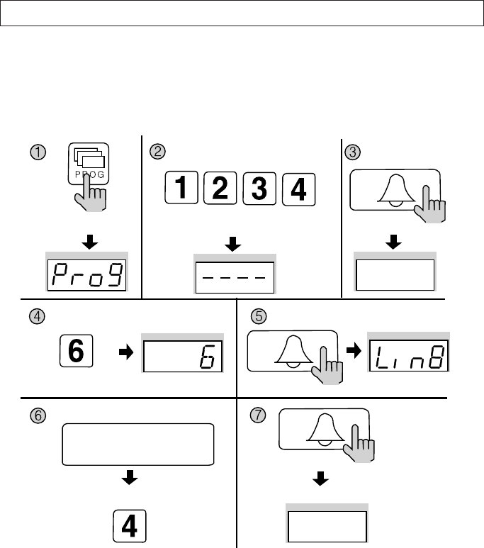
12. Wiring Method Selection
P - Building (Management) PIN - E - 6 - E - 4 - E: 4-wire Common Method (12-wire common)
P - Building (Management) PIN - E - 6 - E - 8 - E: 8-wire Common Method
Video images from the Main Entrance cannot be viewed in the Household when the
8-wire Common Method has been selected.
①Press the Program button (P). (‘Prog’will appear)
②Enter the Building (Management) PIN.
③Press the Call button (E).
④Press number 6 (Wiring Method Selection).
⑤Press the Call button (E). (Previous selection is displayed)
⑥Select a wiring method.
4: 4-wire Common Method (12-wire common)
8: 8-wire Common Method
⑦Press the Call button (E). (Wiring method updated)
Press the Program button (P). Enter the Building (Management) PIN.
ex) Building PIN Press the
Call button (E).
The current capacity
is displayed.
Press the
Call button (E).
Press the
Call button (E).
Press the Program Number (6).
Select a wiring method
4: 4-wire Common Method
(12-wire common)
8: 8-wire Common Method
Wiring method updated
ex) Wiring method selected 4- wire commom method
DRC-481L/DRC-500L-영 문 2006.10.26 1:23 PM 페이지26
- 27 -
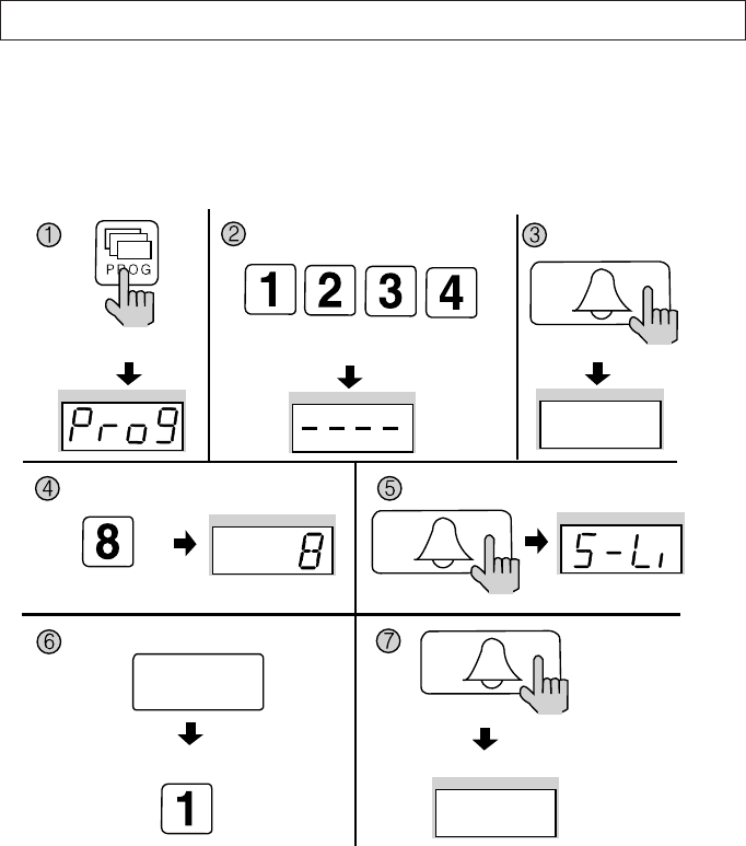
13. Video Out Impedance Adjustment
P - Building (Management) PIN - E - 8 - E - 0 - E: Short Distance
P - Building (Management) PIN - E - 8 - E - 1 - E: Long Distance
By default, the unit is set for short distance.
Do not change if possible.
①Press the Program button (P). (‘Prog’will appear)
②Enter the Building (Management) PIN.
③Press the Call button (E).
④Press number 8 (Impedance Setup).
⑤Press the Call button. (The previous selection is displayed)
⑥Select the impedance.
0 : Short Distance
1 : Long Distance
⑦Press the Call button (E). (Impedance selection updated)
Press the Program button (P). Enter the Building (Management) PIN.
ex) Building PIN Press the
Call button (E).
The current capacity
is displayed.
Press the
Call button (E).
Press the
Call button (E).
Press the Program Number (8).
Select the Impedance
0: Short Distance
1: Long Distance
Impedance selection updated
ex) Impedance Adjusted
short distance
DRC-481L/DRC-500L-영 문 2006.10.26 1:23 PM 페이지27
- 28 -
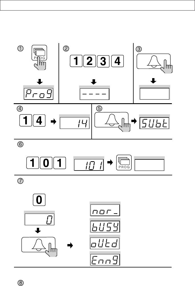
14. Household Interphone Diagnosis
P - Building (Management) PIN - E - 14 - E - Household Number - E
This feature checks for the Household Interphone’s operating conditions.
Press the Program button (P). Enter the Building (Management) PIN.
ex) Building PIN
Press the
Call button (E).
Check feature the
Household Videophone
Press the
Call button (E).
Press the
Call button (E).
Press the Program Number (14).
Enter the Household Number, then press the Program button.
Enter the Multi Sub Number, then press the Page button (E).
You can check the whole households in the same way.
After checkup, push the cancel button.
After checking the currently displayed household, it will show automatically a next household.
Push the call button to check a next household.
ex) check for 101
ex) check for master status
The Household’s status is shown on the display window (FND).
Normal status
Busy status
Away status
Emergency status
DRC-481L/DRC-500L-영 문 2006.10.26 1:24 PM 페이지28
- 29 -
①Press the Program button (P). (‘Prog’will appear)
②Enter the Building (Management) PIN.
③Press the Page button (E).
④Enter number 14 (Household Interphone Diagnosis).
⑤Press the Page button (E). (‘Subt’will appear)
⑥Enter the Household Number, then press the Program button.
⑦Enter the Multi Sub Number, then press the Page button (E).
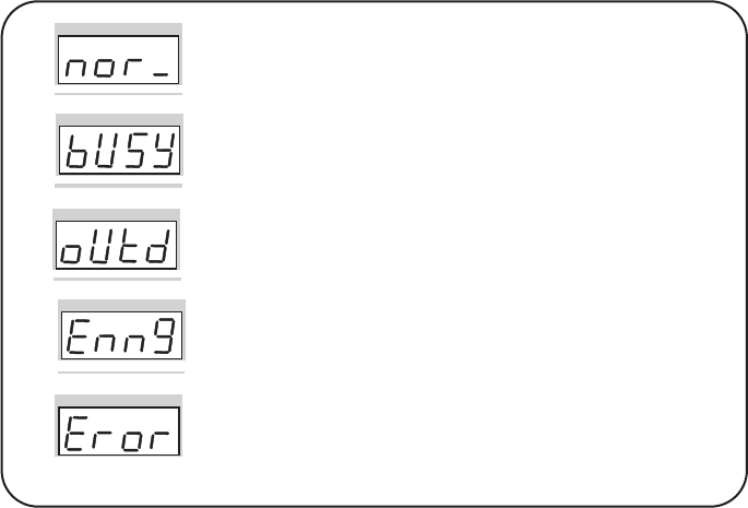
The Household’s status is shown on the display window (FND).
(Please refer to the following indications)
⑧To check other Households, repeat steps 6 and 7.
Press the Cancel button (X) to terminate the feature.
Household Status
Normal Status - The Household is in standby.
(Normal will also be indicated if the Household is in
conversation with the Entrance or on the phone)
Busy Status - The Household is on the phone.
(Busy status is only shown when in conversation with the
Guardhouse)
Away Status - Residents are currently away from their
Household.
Emergency Status - There is an emergency situation in the
Household.
(Emergency, Warning 1 (Fire), Warning 2 (Gas), Burglary, and
etc are indicated as emergency situations)
Error Status - Connection could not be established with the
Household. (Please check the Household Videophone)
DRC-481L/DRC-500L-영 문 2006.10.26 1:24 PM 페이지29
- 30 -
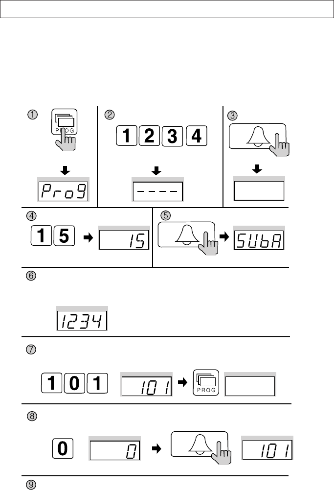
15. Household Number Registration
P - Building (Management) PIN - E - 15 - E - Guardhouse page from the Household -
Household Number - P - Serial Numbe - E
This feature is used to register Household Numbers through the Main Entrance
Interphone when the Guardhouse Interphone has not been installed. If the
Guardhouse Interphone is available, please use it to register.
Press the Program button (P). Enter the Building (Management) PIN.
ex) Building PIN
Press the
Call button (E).
Household PIN
Entry Mode
Press the
Call button (E).
Press the
Call button (E).
Press the Program Number (15).
Lift up the receiver from the Household and press the Guard button to page the Main Entrance
Interphone, where the Household Number will be displayed.
(Then, the displayed number must be changed for it is the default number from the factory.)
Enter the Household number and press the Program button.
ex) Entering as first
1234
ex) Entering as Unit 101
Enter the Multi Sub number and press the Page button (E).
Follow the same procedure to enter other Households.
Press the Cancel button (X) to end.
ex) Entering as Master
DRC-481L/DRC-500L-영 문 2006.10.26 1:24 PM 페이지30

- 31 -
<Note>
What is Multi Sub Number?
Refers to individual numbers for each videophone in the Household when there is
more than one.
The Master’s Serial Number is 0.
Sub Serial Numbers are from 1 to 9.
Maximum 10 videophones can be installed in a household, and their serial
numbers must not overlap.
A Master must exist among numerous videophones. If only one videophone
exists, that unit shall be registered as the Master.
When ADT-481 is installed in the Household, that unit will not be registered as the
Master.
①Press the Program button (P). (‘Prog’will appear)
②Enter the Building (Management) PIN.
③Press the Page button (E).
④Enter number 15 (Household Number Registration).
⑤Press the Page button (E). (‘SUbA’will appear)
⑥Lift up the receiver from the Household and press the Guard button to page the Main
Entrance Interphone, where the Household Number will be displayed. Then, the
displayed number must be changed for it is the default number from the factory.
⑦Enter the Household number and press the Program button.
⑧Enter the Multi Sub number and press the Page button (E).
⑨The Main Entrance Interphone’s Display Window will convert to the (5) status.
⑩To enter different Households, repeat steps 6 and 7.
⑪Press the Cancel button (X) to end.
DRC-481L/DRC-500L-영 문 2006.10.26 1:24 PM 페이지31
- 32 -
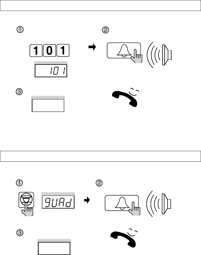
16. Paging the Household
17. Paging the Guardhouse
Enter theHousehold Number.
Press the Guard button. Press the Page button.
A paging tone will sound.
Wait for a reply
Wait for a reply
Press the page button.
A paging tone will sound.
Press the
Call button (E).
Press the
Call button (E).
ex) unit 101
DRC-481L/DRC-500L-영 문 2006.10.26 1:24 PM 페이지32
- 33 -
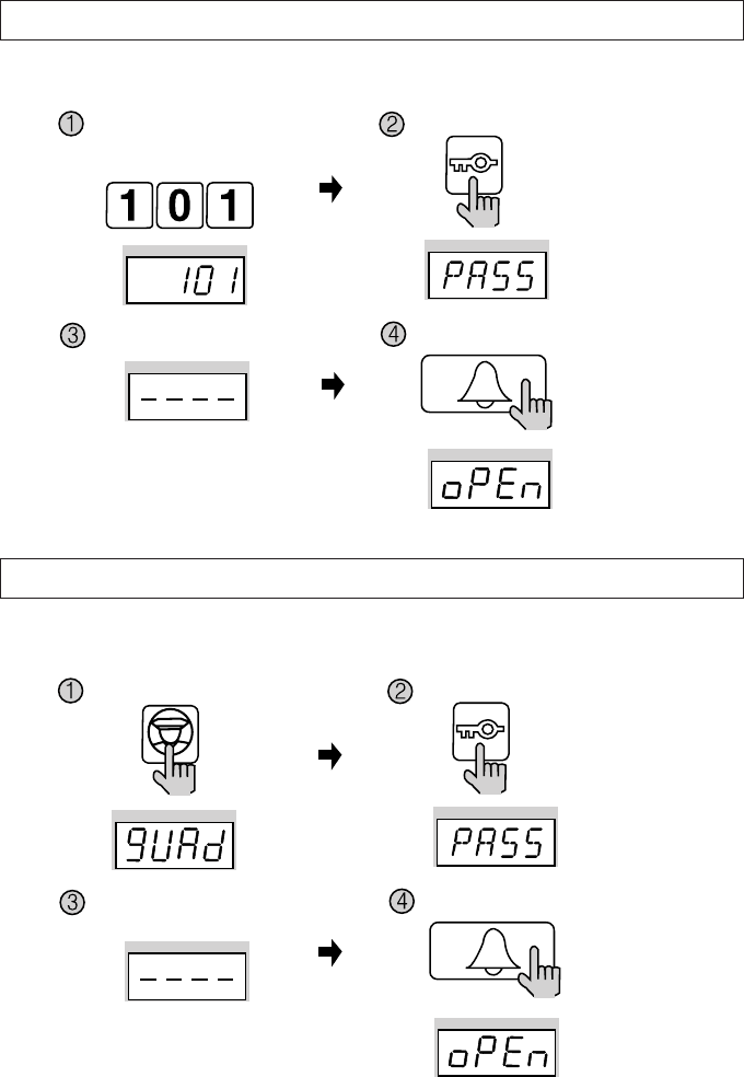
18. Door Release Using the Household PIN
19.
Door Release Using the Building (Management) PIN
Household Number - K - Household PIN - E
G - K - Building (Management) PIN - E
Enter the Household Number.
Press the Guard button.
Enter the Household PIN. Press the Page button.
Press the Page button.
Enter the Building or the
Management PIN.
Press the Electronic key button.
Press the Electronic key button.
Press the Call button (E).
Press the Call button (E).
ex) To open the door of unit 101
DRC-481L/DRC-500L-영 문 2006.10.26 1:24 PM 페이지33

- 34 -
20. Appendix (Various Program Summaries)
Various PIN Programs
1. P - Old Management PIN - E - 0 - E - New PIN- E: Management PIN Change
2. P- Old Building PIN - E -1 - E - New PIN - E: Building PIN Change
3. K - 20 - E - Household Number - E - Old Household PIN - E - New PIN - P: Household PIN
Change
4. P - Building (Management) PIN - E - 16 - E - Household Number - E: Household PIN
Confirmation
Configuring Building and Serial Numbers from the Main Entrance Interphone
1. P - Building (Management) PIN - E - 2 - E - Building Number - E: Building Number Setup
2. P - Building (Management) PIN - E - 3 - E - Serial Number - E: Serial Number Setup
Remote Cardkey Programs
1. P - Building (Management) PIN - E - 9 - E: Remote Cardkey Test
2. P - Building (Management) PIN - E - 10 - E: Remote Cardkey Registration
3. P - Building (Management) PIN - E - 11 - E: All Remote Cardkey Delete (Household PIN
Delete)
4. P - Building (Management) PIN - E - 12 - E: Individual Cardkey Delete
5. P - Building (Management) PIN - E - 13 - E: Remote Cardkey Confirmation
6. P - Building (Management) PIN - E - 19 - E: Expanding Remote Cardkey Capacity
Door Release Using Various PINs
1.GP - KP - Building (Management) PINP - E: Door release using Building (Management) PIN
2.Household NumberP - KP - Household PINP - E: Door release using Household PIN
Other Feature Setup Methods
1.P - Building (Management) PIN - E - 4 - E: Surveillance Monitor Setup
2.P - Building (Management) PIN - E - 5 - E: Door Release Time Setup
3.P - Building (Management) PIN - E - 6 - E: Wiring Method Selection
4.P - Building (Management) PIN - E - 7 - E: Paging Tone Selection
5.P - Building (Management) PIN - E - 8 - E: Video Out Impedance Selection
6.P - Building (Management) PIN - E - 14 - E: Household Interphone Diagnosis
7.P - Building (Management) PIN - E - 15 - E: Household Number Registration
8. P - Building (Management) PIN - E - 17 -
- 34 -
DRC-481L/DRC-500L-영 문 2006.10.26 1:24 PM 페이지34
- 35 -
21. Wiring Method
1-2 : Call 1 (TIV 0.65mm×2C Non Polar)
3-4 : Call 2 (TIV 0.65mm×2C Non Polar)
5-6 : Call 3 (TIV 0.65mm×2C Non Polar)
7-8 : Call 4 (TIV 0.65mm×2C Non Polar)
9-10 : Call 5 (TIV 0.65mm×2C Non Polar)
11-12 : Call 6 (TIV 0.65mm×2C Non Polar)
13-14 : Call 7 (TIV 0.65mm×2C Non Polar)
15-16 : Call 8 (TIV 0.65mm×2C Non Polar)
17 : Data (TIV 0.65mm Polar)
18 : GND (TIV 0.65mm Polar)
1-2 : Call 1 (TIV 0.65mm×2C Non Polar)
3-4 : Call 2 (TIV 0.65mm×2C Non Polar)
5-6 : Call 3 (TIV 0.65mm×2C Non Polar)
7-8 : Call 4 (TIV 0.65mm×2C Non Polar)
9-10 : Call 5 (TIV 0.65mm×2C Non Polar)
11-12 : Call 6 (TIV 0.65mm×2C Non Polar)
13-14 : Call 7 (TIV 0.65mm×2C Non Polar)
15-16 : Call 8 (TIV 0.65mm×2C Non Polar)
1) Guardhouse Interphone (CDS-481L)
For Computer
Connection
(Optional)
Connection to a
Computer
Rear Code Terminal
Rear Code Terminal
Talk 1~8, Data
Terminal for connection
with external Phone lines.
Talk 9~16, Data
Talk 1
Talk 2
Talk 3
DATA
GND
Bk Br R Or Y G B Pu G Bk Br R Or Y G B Pu G
For Internal
Phone Line
Bk: Black
Br: Brown
R: Red
Or: Orange
Y: Yellow
G: Green
B: Blue
Pu: Purple
G: Gray
DRC-481L/DRC-500L-영 문 2006.10.26 1:24 PM 페이지35
- 36 -
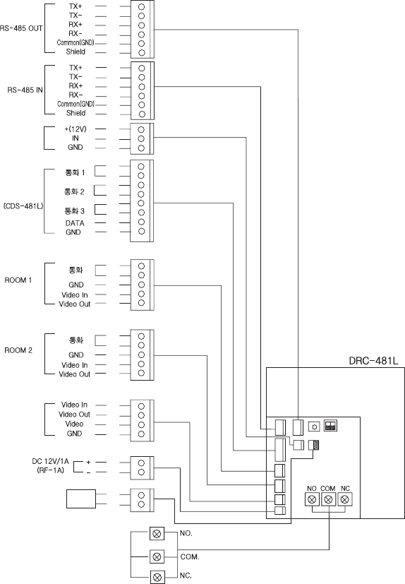
Security
①DC 12V used.
②Designed to be used by connecting to the lead switch. When not in use, please connect two wires.
③When the Main Entrance is opened by force, the Guardhouse and the computer are notified.
Bk
Br
R
Or
Y
G
Bk
Br
R
Or
Y
G
B
Pu
Bk
Br
R
Or
Y
Bk
Br
R
Or
Y
R
B
Y
W
R
B
R
Y
Bk
Br
R
Or
Y
G
R
B
Y
Bk: Black
Br: Brown
R: Red
Or: Orange
Y: Yellow
G: Green
B: Blue
Pu: Purple
G: Gray
W: White
Infrared Sensor
Guardhouse
Monitor
Door Release
Mechanism
Security
(Household
Videophone)
(Household
Videophone)
2) Main Entrance Interphone (DRC-481L)
DRC-481L/DRC-500L-영 문 2006.10.26 1:24 PM 페이지36
- 37 -
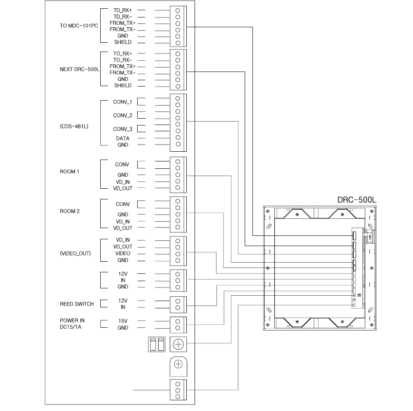
(DRC-500L)
Security
①Use DC 15V.
②It is designed to use a reed switch. When it is not used, connect two lines.
③When the main entrance door is forced to open, it will be notified to the guardhouse and a
computer.
Bk
Br
R
Or
Y
G
Bk
Br
R
Or
Y
G
B
Pu
Bk
Br
R
Or
Y
Bk
Br
R
Or
Y
R
B
Y
W
R
B
Y
R
B
R
Y
Bk
Br
R
Or
Y
G
Bk: Black
Br: Brown
R: Red
Or: Orange
Y: Yellow
G: Green
B: Blue
Pu: Purple
G: Gray
W: White
Infrared Sensor
Guardhouse
Monitor
Door Release
Terminal
(Household
Videophone)
(Household
Videophone)
DRC-481L/DRC-500L-영 문 2006.10.26 1:24 PM 페이지37
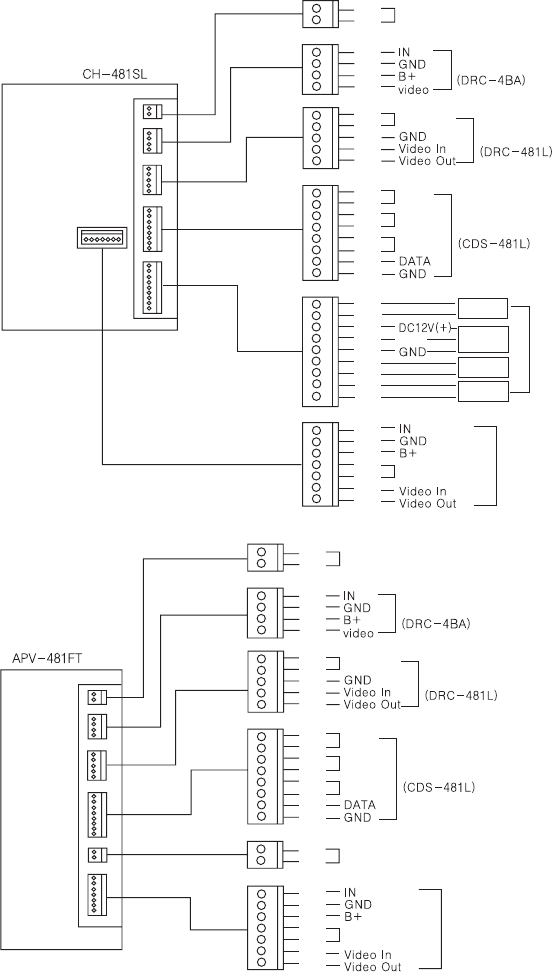
- 38 -
Bk: Black
Br: Brown
R: Red
Or: Orange
Y: Yellow
G: Green
B: Blue
Pu: Purple
G: Gray
W: White
Telephone
Main Entrance
Talk
Talk 1
Talk 2
Talk 3
Talk
Talk 1
Talk 2
Talk 3
Warring1
Warring2
Burglar
Emergency
Guardhouse
Sensor
Sensor
Extention
Main Entrance Call
Household Camera
Telephone
Main Entrance
Main Entrance Call
Guardhouse
Emergency
Extention
Household Camera
R
B
R
B
Y
W
Bk
Br
R
Or
Y
G
B
Pu
Bk
Br
R
Or
Y
G
B
Pu
G
Bk
Br
R
Or
Y
G
B
R
B
R
B
Y
W
Bk
Br
R
Or
Y
Bk
Br
R
Or
Y
G
B
Pu
R
B
Bk
Br
R
Or
Y
G
B
Bk
Br
R
Or
Y
3) Household Videophone(CH-481SL)
4) Household Videophone(APV-481FT)
DRC-481L/DRC-500L-영 문 2006.10.26 1:24 PM 페이지38
- 39 -
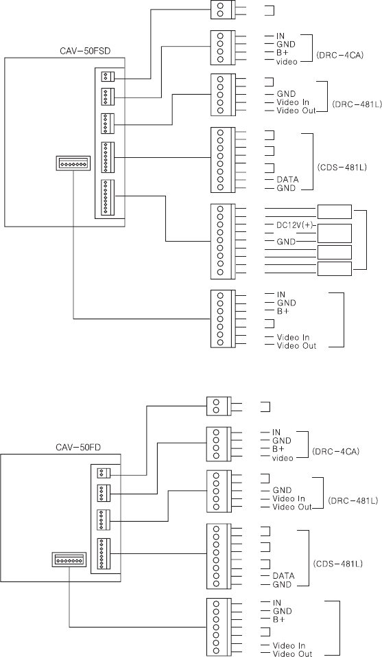
5) Household Videophone(CAV-50FSD)
6) Household Videophone(CAV-50FD)
Bk: Black
Br: Brown
R: Red
Or: Orange
Y: Yellow
G: Green
B: Blue
Pu: Purple
G: Gray
W: White
Telephone
Main Entrance
Talk
Talk 1
Talk 2
Talk 3
Warring1
Warring2
Burglar
Emergency
Guardhouse
Sensor
Sensor
Extention
Main Entrance Call
Household Camera
R
B
R
B
Y
W
Bk
Br
R
Or
Y
G
B
Pu
Bk
Br
R
Or
Y
G
B
Pu
G
Bk
Br
R
Or
Y
G
B
Bk
Br
R
Or
Y
Talk
Talk 1
Talk 2
Talk 3
Telephone
Main Entrance
Main Entrance Call
Guardhouse
Extention
Household Camera
R
B
R
B
Y
W
Bk
Br
R
Or
Y
G
B
Pu
Bk
Br
R
Or
Y
G
B
Bk
Br
R
Or
Y
DRC-481L/DRC-500L-영 문 2006.10.26 1:24 PM 페이지39
- 40 -
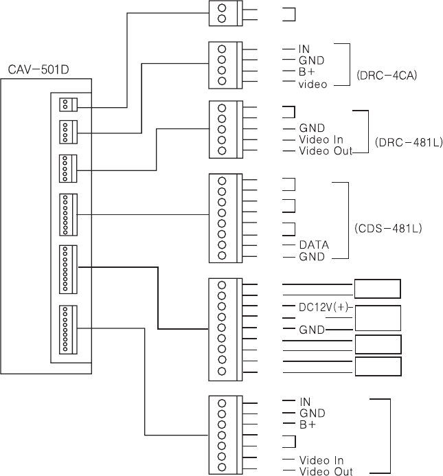
7) Household Videophone(CAV-501D)
Telephone
Main Entrance
Talk
Talk 1
Talk 2
Talk 3
Warring1
Warring2
Burglar
Emergency
Guardhouse
Sensor
Extention
Main Entrance Call
Household Camera
R
B
R
B
Y
W
Bk
Br
R
Or
Y
G
B
Pu
Bk
Br
R
Or
Y
G
B
Pu
G
Bk
Br
R
Or
Y
G
B
Bk
Br
R
Or
Y
Bk: Black
Br: Brown
R: Red
Or: Orange
Y: Yellow
G: Green
B: Blue
Pu: Purple
G: Gray
W: White
DRC-481L/DRC-500L-영 문 2006.10.26 1:24 PM 페이지40
- 41 -
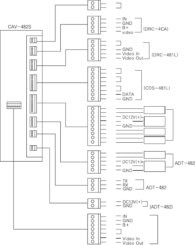
8) Household Videophone(CAV-482S)
Telephone
Main Entrance
Talk
Talk 1
Talk 2
Talk 3
Warring1
Warring2
Burglar
Emergency
Burglar 1
Burglar 2
Guardhouse
Sensor
Sensor
Sensor
Sensor
Extention
Power
Communication
Main Entrance Call
Household Camera
R
B
R
B
Y
W
Bk
Br
R
Or
Y
G
B
Pu
Bk
Br
R
Or
Y
G
B
Pu
G
Bk
Br
R
Or
Y
Bk
Br
R
Or
Y
G
B
Bk
Br
R
R
Y
Bk
Br
R
Or
Y
Bk: Black
Br: Brown
R: Red
Or: Orange
Y: Yellow
G: Green
B: Blue
Pu: Purple
G: Gray
W: White
DRC-481L/DRC-500L-영 문 2006.10.26 1:24 PM 페이지41
- 42 -
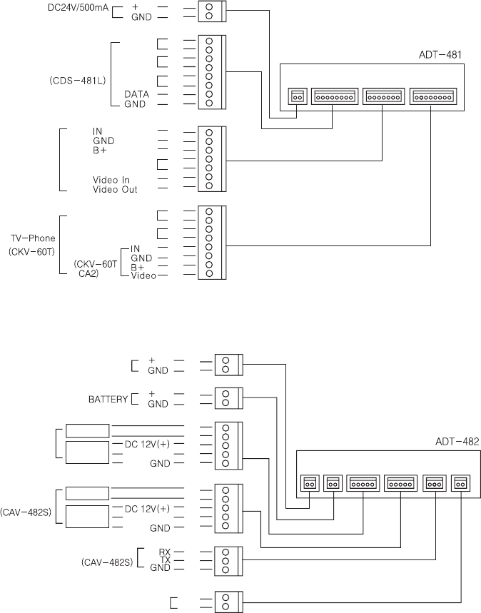
9) TV-Phone Interface Adaptor(ADT-481)
10) Security Interface Adaptor(ADT-482)
R
B
Unit DC
Guardhouse
Talk 1
Talk 2
Talk 3
Extention
Camera
Power
(Supply of CAV-482S)
Guardhouse(CKV-60T)
Door Release(CKV-60T)
Main Entrance Call
Bk
Br
R
Or
Y
G
B
Pu
Bk
Br
R
Or
Y
G
B
Bk
Br
R
Or
Y
G
B
Pu
R
B
R
B
R
B
Bk
Br
R
Or
Y
Bk
Br
R
Or
Y
Bk
Br
R
Bk: Black
Br: Brown
R: Red
Or: Orange
Y: Yellow
G: Green
B: Blue
Pu: Purple
G: Gray
W: White
Burglar 1
Burglar 2
Burglar 1
Burglar 2
Sensor
Sensor
Sensor
Sensor
Telephone
Communication
DRC-481L/DRC-500L-영 문 2006.10.26 1:24 PM 페이지42
- 43 -
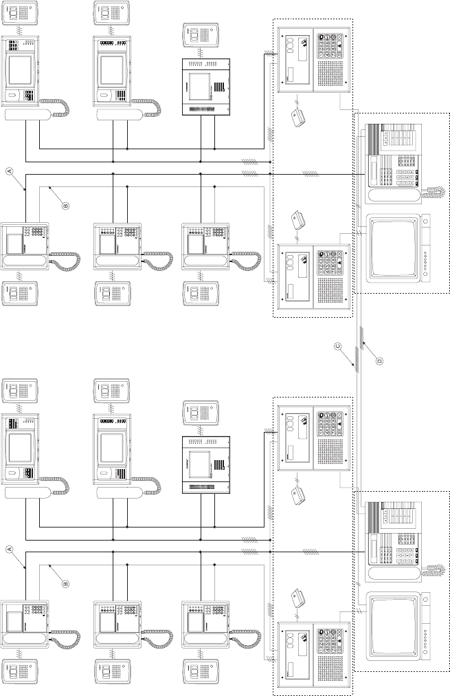
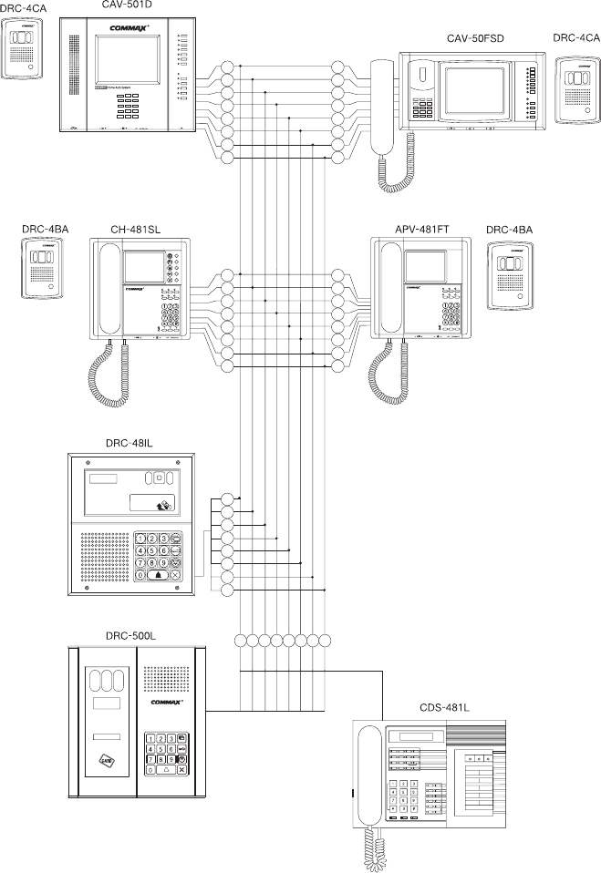
11) System Map
※Note
: Guardhouse Line (Common 8-wire)
: Main Entrance Line (Common 4-wire)
: External Call Line (Common 18-wire)
: Enternal Extension Line (Common 16-wire) →Optional
Lobby
Phone
Lobby
Phone
Lobby
Phone
Lobby
Phone
Lobby 2
Lobby 1
Lobby 2
Lobby 1
Common 4
Czmera
Household
Videophone
Czmera
Household
Videophone
Common 4
Monitor
Monitor Guardhouse Guardhouse
DRC-481L/DRC-500L-영 문 2006.10.26 1:24 PM 페이지43
- 44 -
12) Wiring Method for Communications with the Guardhouse
Bk
Br
R
Or
Y
G
B
Pu
Bk
Br
R
Or
Y
G
B
Pu
Bk
Br
R
Or
Y
G
B
Pu
Bk
Br
R
Or
Y
G
B
Pu
Bk Br R Or Y G B Pu
Bk
Br
R
Or
Y
G
B
Pu
Bk: Black
Br: Brown
R: Red
Or: Orange
Y: Yellow
G: Green
B: Blue
Pu: Purple
G: Gray
W: White
DRC-481L/DRC-500L-영 문 2006.10.26 1:24 PM 페이지44
- 45 -
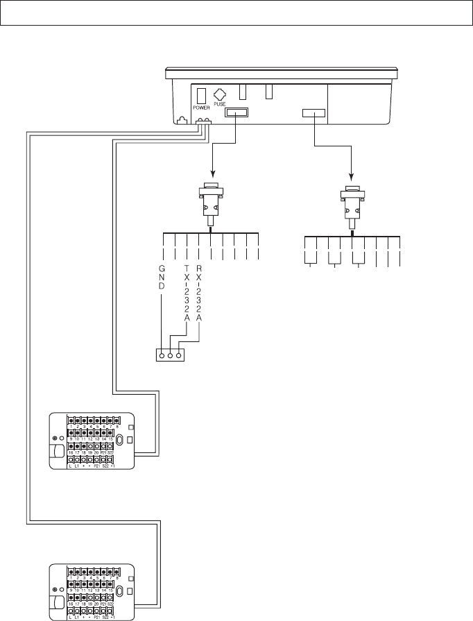
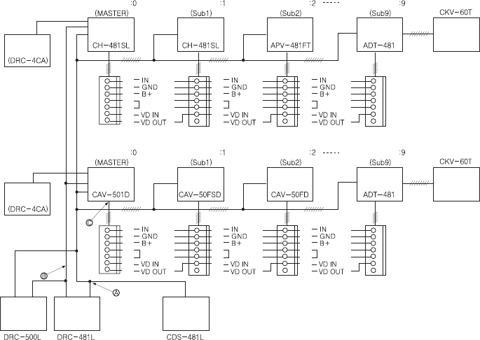
13) Main Entrance Interphone Wiring
※NOTE
1. Main Entrance System
Bk
Br
R
Or
Y
CALL
GND
VD/IN
VD/OUT
2. Household Videophone
Bk
Br
R
Or
Y
CALL
GND
VD/IN
VD/OUT
3. If the Guardhouse Interphone (CDS-481L) has been installed, Number 7 (Data) and 8 (GND)
connected to it must be connected to the Household Interphone.
4. Use coaxial cables (3C2V or 5C2V) for Video Out.
Bk
Br
R
Or
Y
Bk
Br
R
Or
Y
Bk
Br
R
Or
Y
Bk
Br
R
Or
Y
Bk
Br
R
Or
Y
Bk
Br
R
Or
Y
Bk
Br
R
Or
Y
Bk
Br
R
Or
Y
Bk: Black
Br: Brown
R: Red
Or: Orange
Y: Yellow
G: Green
B: Blue
Pu: Purple
G: Gray
W: White
Camera 1
Camera 2
DRC-481L/DRC-500L-영 문 2006.10.26 1:24 PM 페이지45
- 46 -
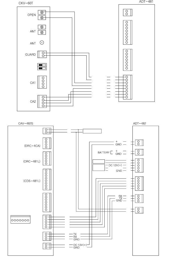
14) Wiring ADT-481 and CKV-60T
15) Wiring ADT-482 and CAV-482S
Bk
Br
R
Or
Y
G
B
Pu
Bk
Br
R
Or
Y
Bk
Br
R
Or
Y
Bk
Br
R
Or
Y
Bk
Br
R
R
B
R
B
R
B
R
B
R
B
R
B
Y
Guardhouse
Guardhouse
OPEN/CLOSE
OPEN/CLOSE
IN
GND
B+
VD
Bk: Black
Br: Brown
R: Red
Or: Orange
Y: Yellow
G: Green
B: Blue
Pu: Purple
G: Gray
W: White
Telephone Telephone
Main Entrance
Guardhouse
Sensor
Sensor
Sensor
Extention
Communication
Household Camera
Burglar 1
Burglar 2
DRC-481L/DRC-500L-영 문 2006.10.26 1:24 PM 페이지46
- 47 -
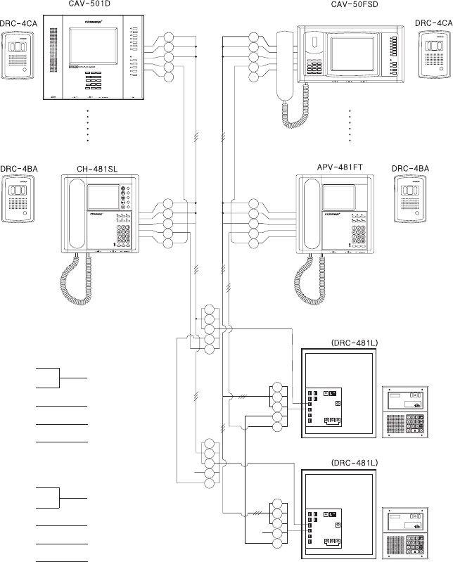
16) Installing Numerous Videophones in a Household
※NOTE
1. : Guardhouse Line (8-wire Common)
: Main Entrance Line (4-wire Common)
: Sub Extension (6-wire Common)
2. When registering the Multi Sub number, ADT-481 will not be recognized as the Master and should be
installed last as shown above.
3. Various types of sensors should be connected to the Master, and sensors of the remaining Subs should be
connected with the + wire and the sensor line: if the two lines are not connected, the Away mode will not
function.
Bk
Br
R
Or
Y
G
B
Bk
Br
R
Or
Y
G
B
Bk
Br
R
Or
Y
G
B
Bk
Br
R
Or
Y
G
B
Bk
Br
R
Or
Y
G
B
Bk
Br
R
Or
Y
G
B
Household
Camera
Household
Camera
Multysub Number
Loby Talk
Loby Talk Loby Talk Loby Talk
Loby Talk Loby Talk
Multysub Number Multysub Number Multysub Number Multysub Number
Multysub Number Multysub Number Multysub Number
DRC-481L/DRC-500L-영 문 2006.10.26 1:24 PM 페이지47
- 48 -
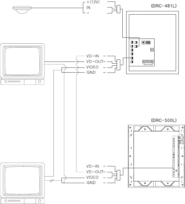
17) CCTV and Sensor Wiring
※NOTE
1. Monitor 1: To view only when being used by the Main Entrance Interphone (DRC-481L).
2. Monitor 2: Continuous surveillance of the Main Entrance.
Monitor 1
CAMERA 1
CAMERA 2
Monitor 2
R
B
Y
R
B
Y
W
R
B
Y
W
R: Red
Y: Yellow
B: Blue
W: White
DRC-481L/DRC-500L-영 문 2006.10.26 1:24 PM 페이지48
- 49 -
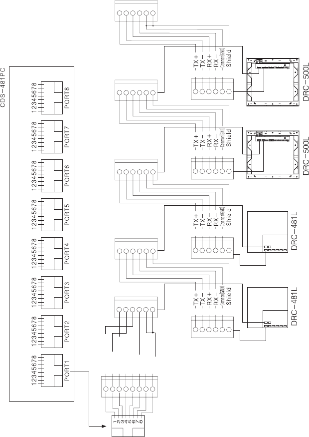
18) Wiring DRC-481L and CDS-481PC
Bk
Br
R
Or
Y
G
①Or(Line)
②Or
③G(Line)
④B
⑤B(Line)
⑥G
⑦Br(Line)
⑧Br
Bk
Br
R
Or
Y
G
Bk
Br
R
Or
Y
G
Bk
Br
R
Or
Y
G
DRC-481L/DRC-500L-영 문 2006.10.26 1:24 PM 페이지49
- 50 -
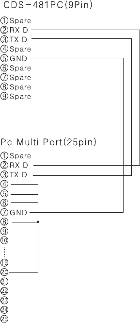
19) Wiring CDS-481PC and Multi Port
DRC-481L/DRC-500L-영 문 2006.10.26 1:24 PM 페이지50
- 51 -
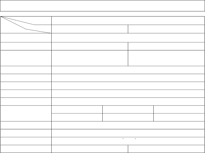
Household Videophone (4-wire Common), Guardhouse Interphone (8-wire Common)
DC12V 1A(RF-1A)
DC15V/1A(CS-15C)
Standby: 200mA, Max: 450mA DC:Standby:400mA, Max:500mA
Hands Free (One Way)
B/W C.C.D 1/3•, COLOR C.C.D. 1/4•
15,735KHz/60Hz, 15,625KHz/50Hz,
Horizontal: 68•Vertical: 55•
0.1Lux(300mm in front of camera)
RF ID 60mm
B/W: Infrared LED×4, COLOR: Lighting necessary at night
-10C•~40C•
230(W)×260(H)×72(D)mm 245(W)×275(H)×63(D)mm
Flush Mounted
DRC-481L DRC-500L
7C2V Coaxial
400m
22. Specifications
Transmission System
Rated Voltage
Power Consumption
Communication Method
Imaging Device
Scanning Frequency
Camera Angle
Minimum Illumination
Communication Distance
Detection Range
Lighting
Ambient Temperature
Dimensions
3C2V Coaxial
200m
5C2V Coaxial
300m
Installation Method
Model
Specfications

- 52 -
MEMO
DRC-481L/DRC-500L-영 문 2006.10.26 1:24 PM 페이지52
DRC-481L/DRC-500L-영 문 2006.10.26 1:24 PM 페이지53

a513-11, Sangdaewon-dong, Jungwon-gu,
Seongnam-si, Gyeonggi-do, Korea
Int’l Business Dept. :
Tel.; +82-31-7393-540~550
Fax.; +82-31-745-2133
Web site : www.commax.com
Printed In Korea
DRC-481L/DRC-500L-영 문 2006.10.26 1:24 PM 페이지54