COP Security System 5800A 5.8GHz Wiress Camera Adaptor User Manual
COP Security System Corp. 5.8GHz Wiress Camera Adaptor Users Manual
UserManual.wiki
>
COP Security System
>
5800A User Manual
Users Manual
Navigation menu
Upload a User Manual
Namespaces
Wiki Guide
HTML
PDF
Info
Views
User Manual
Discussion / Help
Navigation
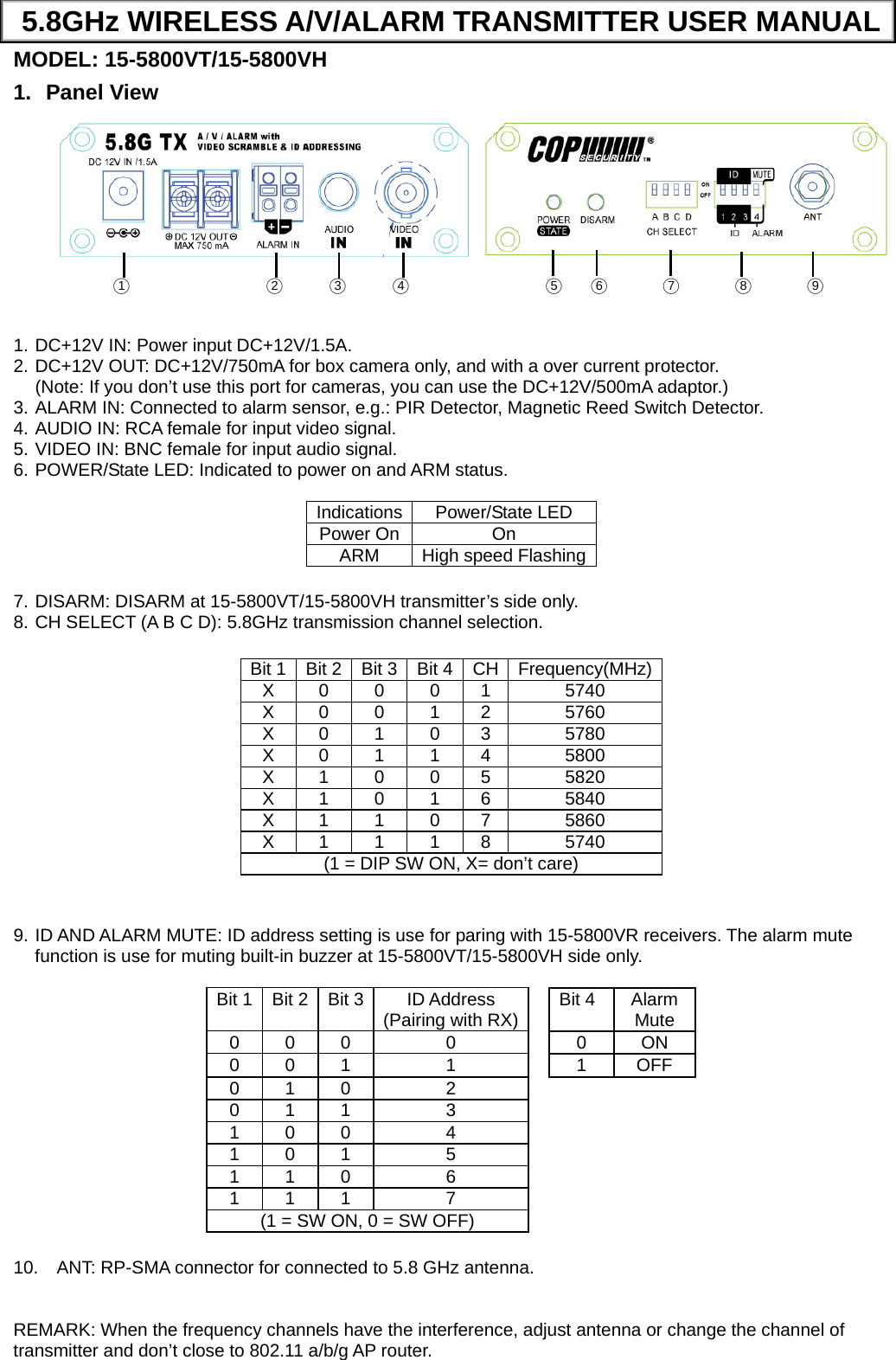
![2. Caution for Installation 2.1 Be careful, never let any water in this equipment. 2.2 If necessary, use a soft cloth moistened with alcohol to wipe off the dust. 2.3 Be extra careful not to shake the unit. 2.4 Avoid places where temperatures exceed 50 o C or higher. 2.5 Avoid places where there are frequent vibrations or shocks. 2.6 When any abnormalities occur, make sure to unplug the unit and contact your local dealer. 3. Packing 3.1 Transmitter ×1 3.2 Antenna ×1 3.3 User manual ×1 3.4 Screws ×4 3.5 Plastic-Conical-Anchor ×4 3.6 Power Adaptor ×1 [Option] 4. Specification CHANNAL CH1 CH2 CH3 CH4 CH5 CH6 CH7 CH8FREQUENCY 5740MHz 5760MHz 5780MHz 5800MHz 5820 MHz 5840 MHz 5860MHz 5740MHzRF ANT. IMPEDANCE 50 Ω Typical POWER DC12V/1.5A Adaptor CURRENT 350mA DC OUTPUT DC12V/750mA OUTPUT POWER 10mW VIDEO INPUT 1 Vp-p Composite @ 50Ω AUDIO INPUT 2 Vp-p @ 600Ω Typical ALARM INPUT TTL/CMOS (Level Detection) DIMENSIONS L:85 mm H:30 mm D:16 mm FCC Part 15 Notice: This equipment has been tested and found to comply with the limits for a Class B digital device, pursuant to part 15 of the FCC rules. These limits are designed to provide reasonable protection against harmful interference in a residential installation. This equipment generates, uses and can radiate radio frequency energy and, if not installed and used in accordance with the instructions, may cause harmful interference to radio communications. However, there is no guarantee that interference will not occur in a particular installation. If this equipment does cause harmful interference to radio or television reception, which can be determined by turning the equipment off and on, the user is encouraged to try to correct the interference by one or more of the following measures: -Reorient or relocate the receiving antenna. -Increase the separation between the equipment and receiver. -Connect the equipment into an outlet on a circuit different from that to which the receiver is connected. -Consult the dealer or an experienced radio/TV technician for help. 1. This Transmitter must not be co-located or operating in conjunction with any other antenna or transmitter. 2. This equipment complies with FCC RF radiation exposure limits set forth for an uncontrolled environment. This equipment should be installed and operated with a minimum distance of 20 centimeters between the radiator and your body. 3. Any changes or modifications (including the antennas) made to this device that are not expressly approved by the manufacturer may void the user’s authority to operate the equipment. Q2009/06/06](https://usermanual.wiki/COP-Security-System/5800A/User-Guide-1129237-Page-2.png)