COSMED Srl K4B2R-USA TELEMETRY UNIT User Manual User man K4B2 en
COSMED Srl TELEMETRY UNIT User man K4B2 en
Contents
- 1. Users Manual I
- 2. Users Manual II
- 3. Users Manual III
- 4. Users Manual IV
Users Manual IV

Resting Metabolic
Rate Test

96 - K4 b2 User Manual
Metabolism
Metabolism can be understood as the conversion by the human body between food and
accumulated fat into energy. The energy is used by the body to maintain constant
temperature , to move and to make all the organ function. Measure of metabolism is:
calories (cal).
Total Metabolic Rate
The total metabolic rate are the total calories that the human body needs in order to
actuate the daily functional activities.
Resting Metabolic Rate (RMR)
Resting Metabolic Rate represents the calories that the vital organs need to properly
operate at rest ( heart , brain , lungs , liver , kidneys etc.) . RMR represents between 60
% and 75 % of the human ‘s total metabolism.
Importance to measure RMR
A knowledge of the RMR is very helpful in order to understand the nutritional needs
and to properly manage it.
Measure of the rest metabolic rate with indirect calorimetry
Energy expenditure can be measured directly by putting a person in a calorimeter and
measuring the amount of heat produced by the body mass.
This is expensive and very impractical in the clinical setting. Energy expenditure can be
measured indirectly with a metabolic cart by analysis of respired gases (usually expired)
to derive volume of air passing through the lungs, the amount of oxygen extracted from
it (i.e., oxygen uptake VO2) and the amount of carbon dioxide, as a by-product of
metabolism, expelled to atmosphere (CO2 output – VCO2). With these measurements
the resting energy expenditure (RMR) and respiratory quotient (RQ) can be calculated.
The RQ represents the ratio of carbon dioxide exhaled to the amount of oxygen
consumed by the individual. RQ is useful in interpreting the results of the RMR. The
abbreviated Weir equation is probably the most common calculation of RMR.
Abbreviated Weir equation:
RMR = [3.9 (VO2) + 1.1 (VCO2)] 1.44
How to perform a RMR test
For best results, when having a REE done, there are certain conditions that need to be
controlled and others that just require documenting at the time of the test. During the
test the individual is interfaced with a metabolic measurement system by means of a
facemask.
A mouthpiece with a nose clip is also sometimes used, but it may create overly stressful
conditions to a subject (patient).
Important considerations or conditions to improve the RMR measurement:
• No food for at least 12 hours and no smoke for at least 2 hours before the test.
• Maintain quiet surroundings when the test is in progress and normal temperature.
The individual should not move arms or legs during the test.
• Medications taken should be noted, such as stimulants or depressants.
• The first 5 minutes of acquisition should be discarded by the computation of RMR
• Steady state should be achieved, which would be identified clinically by the
following criteria: 5 minute period when average minute VO2 and VCO2 changes
by less than 10%, average RQ changes by less than 5%
• Stable interpretable measurements should be obtained in a 15 to 20 minute test.
• Renal failure patients requiring hemodialysis should not be tested during dialysis
therapy.

Chapter 8 - Resting Metabolic Rate Test - 97
Recommendations
Resting metabolic rate test using the face mask
1. Since the ventilation is very low (normally <10 litres/min), the turbine calibration
has to be performed with very slow manoeuvres (each complete manoeuvre in
about 10-15 seconds), to obtain the best accuracy.
2. Use the following correction for the dead space (VD):
- 50 ml for the small mask
- 60 ml for the medium mask
- 70 ml for the large mask
Resting metabolic rate test using the canopy option
1. Verify, before and during the test, that the FeCO2 falls into the range 0.5%-0.8%
and adjust the flow rate of the pump. If the FeCO2 is too low, increase the flow, if it
is too high decrease the flow. In fact, if the FeCO2 is too low the measurement
could be not reliable, while an high FeCO2 could be dangerous for the patient.
2. In order to perform a correct ERGO calibration and to obtein more reliable data
from the test, it is recommended to use a calibration cylinder with the following
concectrations: 1% CO2, 20% O
2, balance N
2. If you use this cylinder, please
remember to modify the reference values, as explained in the chapter Calibration.
98 - K4 b2 User Manual
Performing a test using the face mask
Calibrations
Before the test, it is necessary to perform an ergo calibration (see Calibration chapter)
and it is advisable to perform also a turbine calibration (see Recommendations in this
chapter).
How to prepare a patient
The patient interfaces with the equipment by means of a face mask, like in the stress
exercise. The mask has to be tight to the face, in order to avoid any air leakage.
Start the test
1. Enter in the ergometry program
2. Select a patient or add a new one (File/Patients...)
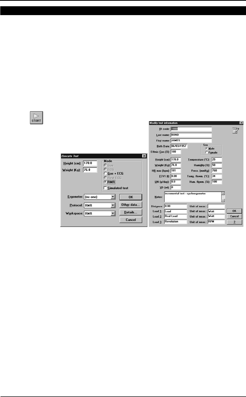
3. Select Start test from Test menu
4. Enter the patient’s data and select the RMR mode (1st picture).
5. Press Other Data… and enter the dead space value (50ml Small mask, 60ml
Medium mask and 70ml Large mask). It is possible to enter the Ureic Nitrogen
value NU (2nd picture).
6. Confirm and start the test by pressing OK.
Selecting RMR the system set automatically the following options:
• Data acquisition with a 30 seconds average
• RMR protocol, which is:
- 5 minutes discarded;
- 10 minutes with data acquisition, of which the software will make an average at
the end of the test;
- automatic end of the test after the 16th minute.
• Selection of the RMR workspace (windows placement);
The test is fully automatic, the software will stop it and save the data at the end of the
16th minute.
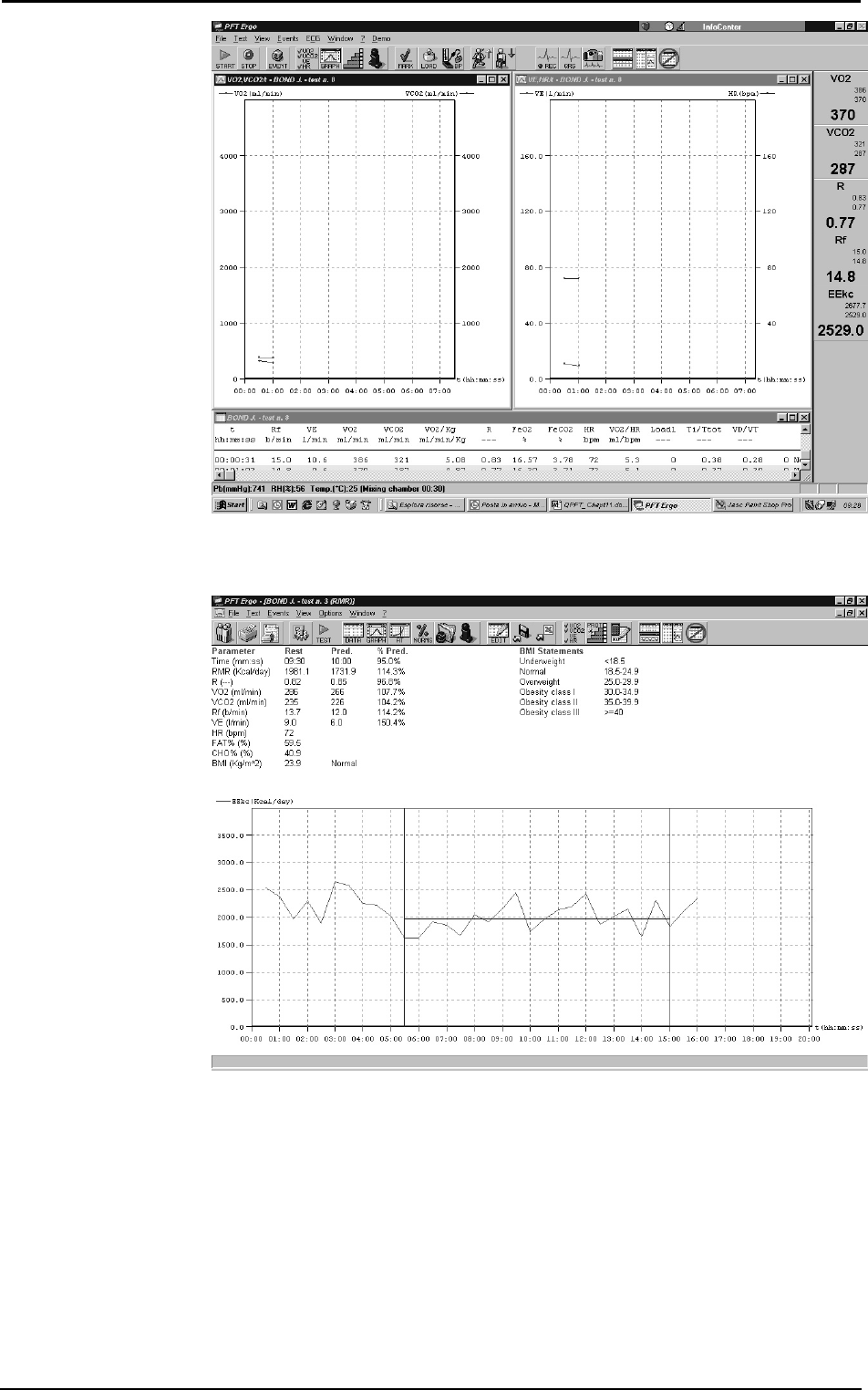
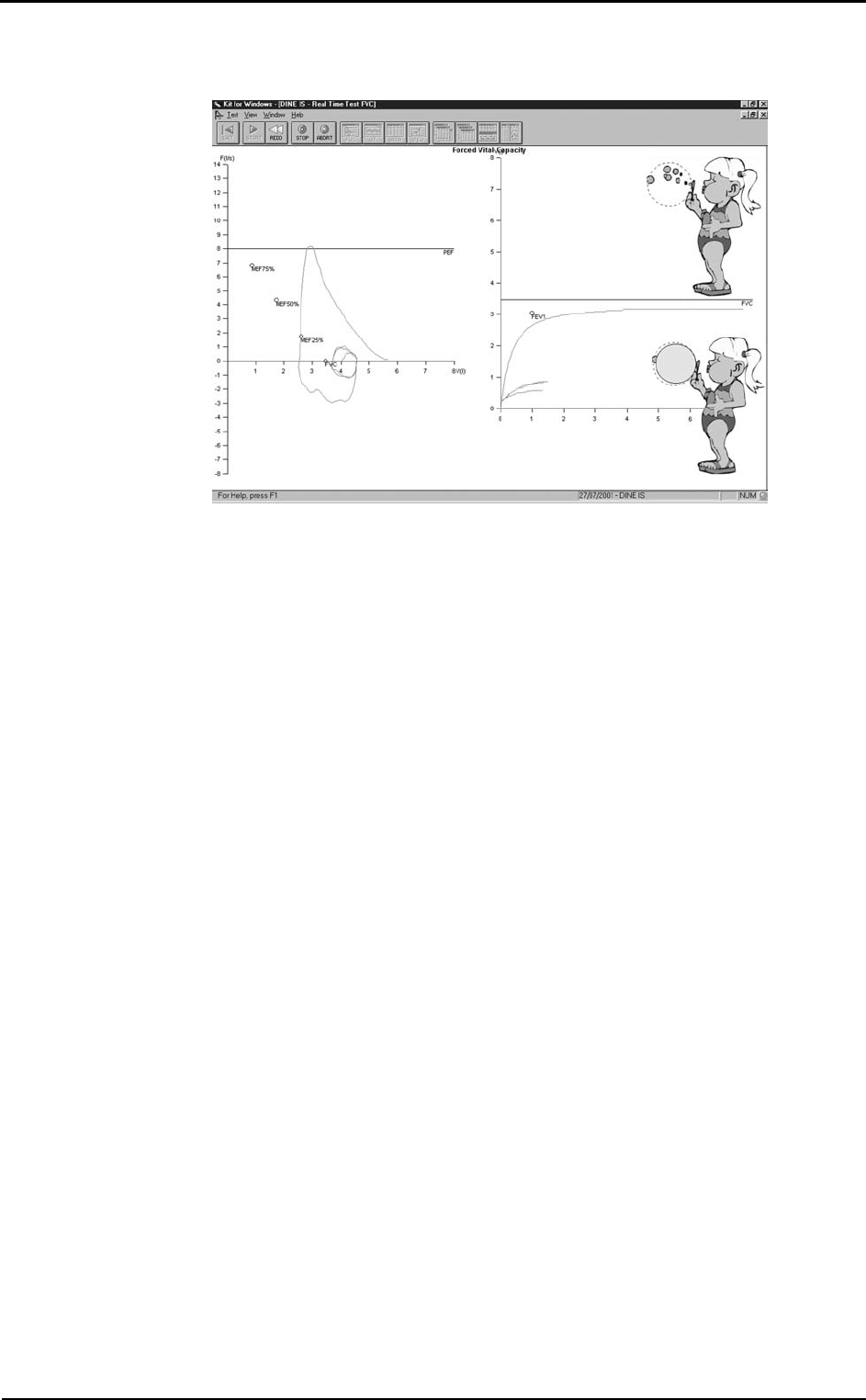
The real time view is as shown in the following picture:
Chapter 8 - Resting Metabolic Rate Test - 99
Viewing the test
At the rend of the test, it will be opened automatically a window with the test results.
At the end of the test, or if it is selected View/RMR, the main results are shown:
• The average time interval (default: 10 minutes)
• Average values of VO2, VCO2, R, RMR, RF, VE, HR, FAT% and CHO% and
predicted values if available.
• Body Mass Index (BMI) and interpretation
• Graph of the energetic expenditure for all the data acquisition interval, highlighting
the selected average interval.
In order to verify the goodness of the test, check that the ventilation and respiratory
frequency are similar to the predicted ones (12 breaths/min for the respiratory frequency
and 6 litres/min for the ventilation), and the heart rate is the rest heart rate of the patient.
sss
Nota:
The percentage of used
Proteins (PRO%) is calculated
assuming 12 grams of Ureic
Nitrogen in 24 hours. You can
modify this value selecting
View/Information… ->
Modify…
100 - K4 b2 User Manual
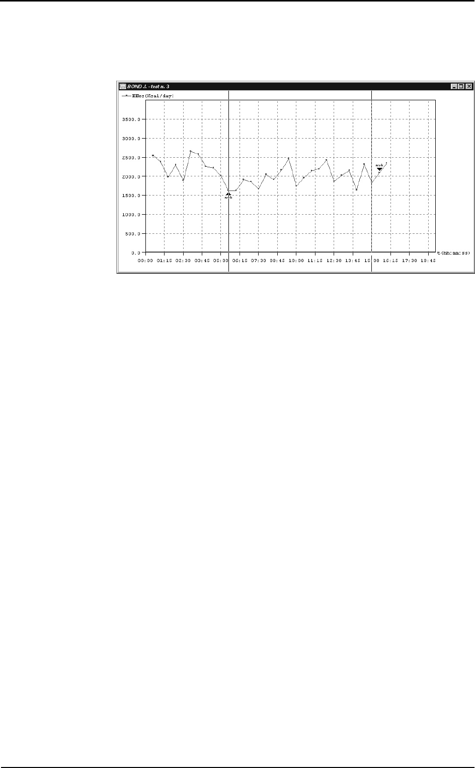
How to modify the average interval
If the average interval (automatically identified by the software) is not satisfying, for
example because the patient was speaking in the first minutes, it is possible to modify
the interval of the average.
Right-click and select Edit RMR…. It is possible to move the start and the end lines.
To move the start line, left-click on the exact time in which you want to start the
calculations, for the end line, right-click.
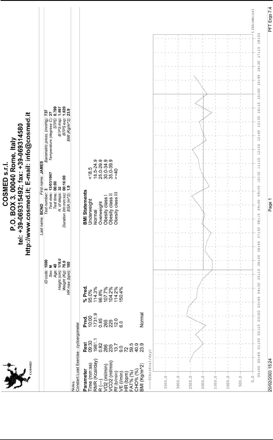
Print
The print of the current window generates a report similar to the one in the following
page.
Chapter 8 - Resting Metabolic Rate Test - 101
102 - K4 b2 User Manual
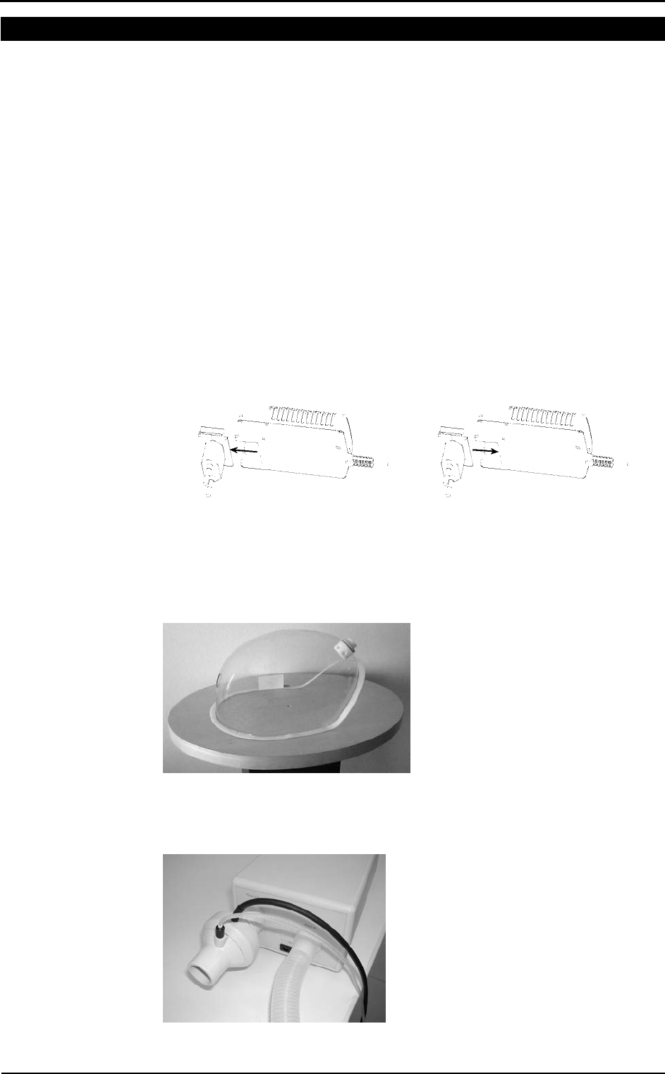
Performing a test using the canopy option
The principle of a ventilated bubblehood system is that a stream of air is forced to pass
across the face of a subject and mixes with the air which is collected by a transparent
hood, placed over the subject’s head. A measurement system, knowing the flow rate,
calulates the oxygen consumption and the CO2 production and, starting from these
values, the energy expenditure.
Calibrations
Before the test, it is necessary to perform an ergo calibration (see Calibration chapter)
and it is advisable to perform also a turbine calibration (see Recommendations in this
chapter).
How to prepare the canopy and the patient
Replacement of the power plug
If the power plug does not fit into the mains socket, replace it with the one in the
packaging.
In order to replace the plug:
1. Extract the plug from the battery charger
2. Insert the proper plug in the battery charger.
Connecting the Canopy
1. Connect the Canopy unit to the mains by means of the medical grade AC/DC
adapter provided.
2. Insert the bubblehood adapter into the bubblehood from the outside and fix it
screwing the ring from the inside, being careful to insert it in the proper hole, as
shown in the following picture.
3. Connect the bubblehood to the wrinkled tube, interposing a bacterial filter.
4. Connect the wrinkled tube to the unit through the Flow in connector.
5. Connect the optoelectronic reader of the Quark to the Flow out connector of the
Canopy unit through the spirometry adapter.
6. Fix the vail to the bubblehood through the velcro strips.
Chapter 8 - Resting Metabolic Rate Test - 103
How to prepare the patient
1. Switch on the Canopy unit. If there are no problems, the red led on the front panel
of the unit flashes for few seconds and the alarm beeps. If the led does not flash
and/or the alarm does not beep, the test cannot be performed, because the backup
battery is exhausted or there is no backup battery.
2. When the green led turns on, the test can start. If the green led does not turn on, the
red led flashes and the alarm beeps, the test cannot be performed because the pump
does not work or the mains does not power the system.
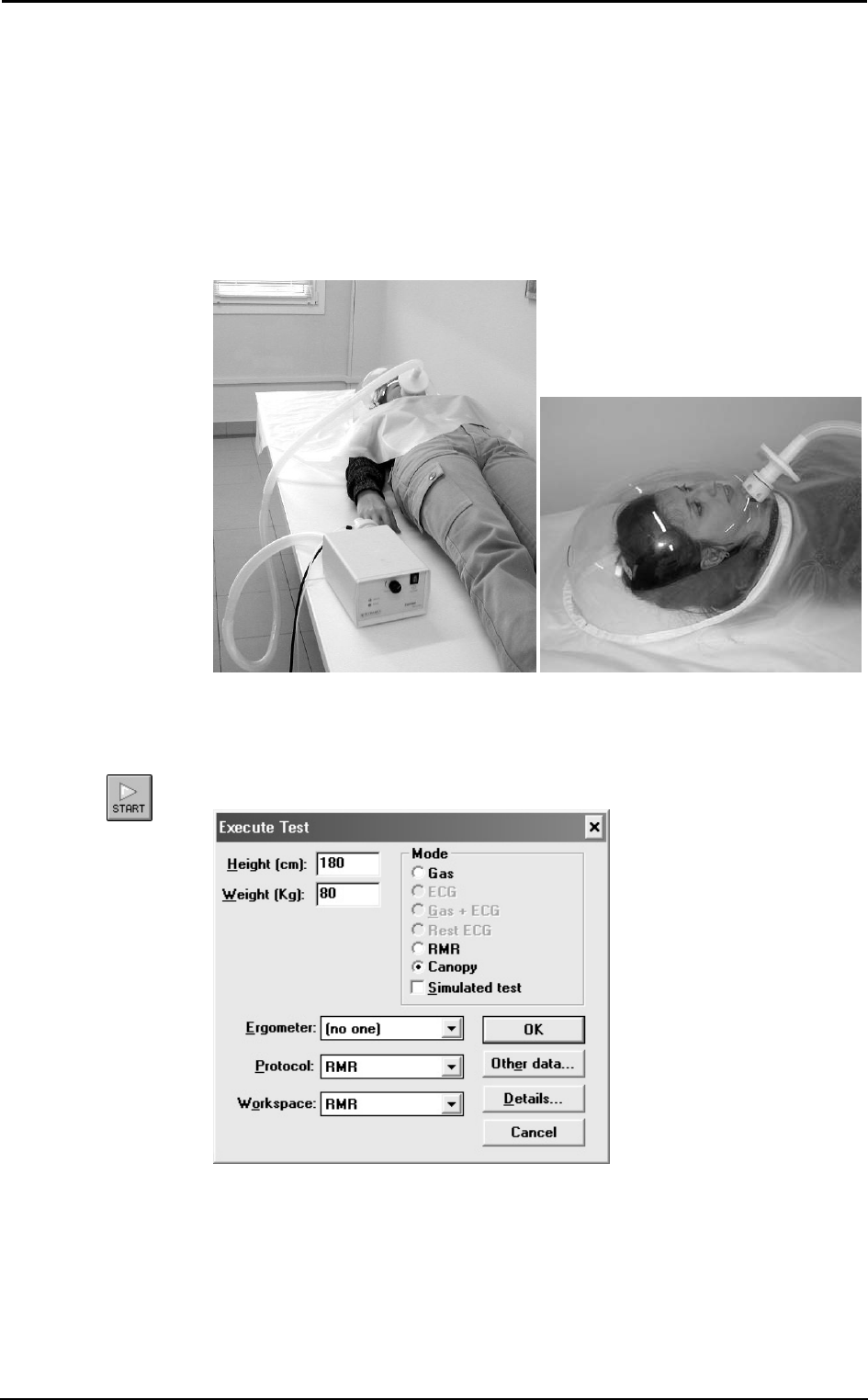
3. After these checks, put the patient in a supine position.
4. Place the bubblehood with the vail on the patient’s head. The tube has to be placed
near the patient’s mouth.
Performing the test
1. Enter in the ergometry program
2. Select a patient or add a new one (File/Patients...)
3. Select Start test from Test menu.
4. Enter the patient’s data and select the Canopy mode.
5. Confirm and start the test by pressing OK.
6. In the first part of the test the flow rate of the pump has to be adjusted by means of
the Flow adjustment handle on the front panel of the Canopy unit, in order to
measure an FeCO2 between 0.5% and 0.8%. FeCO2 values can be read on the right
side of the PC monitor.

104 - K4 b2 User Manual
7. When the FeCO2 remains within the acceptability range, press F2 to start the data
acquisition. Verify, also during the test, that the measured FeCO2 is within the
0.5%-0.8% range. Otherwise, adjust it by means of the Flow adjustment handle.
Warning: If the green led turns off during the test, the red led flashes and the alarm
beeps, abort the test, because the pump does not work or the mains does not power the
system. In the last case, the pump works only because of the backup battery.
The test is fully automatic, the software will stop it and save the data at the end.
Viewing the test
At the rend of the test, it will be opened automatically a window with the test results.
At the end of the test, or if it is selected View/RMR, the main results are shown:
• The average time interval (default: 10 minutes)
• Average values of VO2, VCO2, R, RMR, VE, HR, FAT% and CHO% and predicted
values if available.
• Body Mass Index (BMI) and interpretation
• Graph of the energetic expenditure for all the data acquisition interval, highlighting
the selected average interval.
In order to verify the goodness of the test, check that the FeO2 and FeCO2 values are
within the acceptability ranges (20.2%-20.8% and 0.5%-0.8% respectively), and the
heart rate is the rest heart rate of the patient.
How to modify the average interval
If the average interval (automatically identified by the software) is not satisfying, for
example because the patient was speaking in the first minutes, it is possible to modify
the interval of the average.
Right-click and select Edit RMR…. It is possible to move the start and the end lines.
To move the start line, left-click on the exact time in which you want to start the
calculations, for the end line, right-click.
Print
The print of the current window generates a report similar to the one of the RMR test
using the face mask.
sss
Note:
The percentage of used
Proteins (PRO%) is calculated
assuming 12 grams of Ureic
Nitrogen in 24 hours. You can
modify this value selecting
View/Information… ->
Modify…

Sub-maximal
Exercise Testing

106 - K4 b2 User Manual
Introduction
Several physiological responses to exercise are used to evaluate cardiorespiratory
fitness, including oxygen consumption, heart rate, and blood pressure. Measuring these
variables during exercise, particularly maximum exercise, increase the chance of
detecting any coronary artery disease or pulmonary disease.
Unfortunately, maximum exercise tests are impractical because they are expensive,
require extensive clinical supervision, and subject individuals to levels of physical stress
that may be unnecessary depending on the objectives of the test. Consequently,
maximal testing is reserved for clinical assessments, athletic evaluation, and research.
A sub-maximal exercise test costs less and carries a lower risk for the individual.
Although less sensitive and specific for detecting disease or estimating maximal oxygen
consumption, correctly performed sub-maximal tests can provide a valid estimate of
cardiorespiratory fitness.
Pre-test screening
Pre-test health screening is essential for risk stratification and for determining the type
of test that should be performed and the need for an exercise test prior to exercise
training. A thorough pretest health screening includes the following:
• Complete medical history
• Medical contraindications to exercise
• Symptoms suggesting cardiac or pulmonary disease
• Angina or other forms of discomfort at rest or during exercise
• Unusual shortness of breath at rest or during exercise
• Dizziness or light-headedness
• Orthopaedic complications that may prevent adequate effort or compromise the
validity of test results
• Other unusual signs or symptoms that may preclude testing
• Risk factors for coronary heart disease
• History of major cardiorespiratory events
• Current medications
• Activity patterns
• Nutritional habits
• Reading and signing an informed consent form

Chapter 9 - Sub-maximal Exercise Testing - 107
Sub-maximal exercise testing
Heart rate varies linearly with VO2 to the point of maximum exertion; thus, VO2max may
be estimated using the relation between heart rate and VO2 without subjecting the
individual to maximum levels of physical stress. During sub-maximal exercise testing,
predetermined workloads are used to elicit a steady state of exertion (plateau of heart
rate and VO2). The steady-state heart rate at each work level is displayed graphically
and extrapolated to the VO2 at the age-predicted maximal heart rate (HR = 220-age). A
variety of protocols for different exercise modalities (i.e., treadmill, stationary cycle,
and step increments) can be used as long as the VO2 requirements of each selected
workload can be estimated with accuracy.
The objectives of cardiorespiratory fitness assessments in the apparently healthy
population are as follows:
• Determine the level of cardiorespiratory fitness and establish fitness program goals
and objectives.
• Develop a safe, effective exercise prescription for the improvement of
cardiorespiratory fitness.
• Document improvements in cardiorespiratory fitness as a result of exercise training
or other interventions.
• Motivate individuals to initiate an exercise program or comply with an established
program.
• Provide information concerning health status.
A few assumptions regarding testing are necessary to ensure the highest degree of
accuracy when using sub-maximal exercise testing to estimate VO2max:
• Selected workloads are reproducible. A steady-state heart rate is obtained during
each stage of the test. Usually, workload durations of 3 minutes or more are used to
ensure steady state.
• The maximal heart rate for a given age is uniform (HR = 220-age).
• Heart rate and VO2 have a linear relation over a wide range of values; thus, the
slope of HR/VO2 regression can be extrapolated to an assumed maximum heart
rate.
• Mechanical efficiency (i.e., VO2 at a given work rate) is consistent.
Although if done correctly, sub-maximal exercise tests provide valuable information
concerning cardiorespiratory fitness, they have extremely limited diagnostic capabilities
and should not be used as a replacement for clinical exercise tests or other clinical
treatment or management modalities. Health care professionals should avoid detailed
interpretation beyond the scope of the information obtained.
Considerations with sub-maximal exercise testing
Considerations for selection of protocol and equipment include any physical or clinical
limitations that may preclude certain types of exercise (i.e., age, weight, arthritis,
orthopaedic complications, individual comfort, level of fitness, type of exercise training
that will be performed, and individual preference).
For example, some individuals may perform better on a non-weight-bearing modality
(cycle versus treadmill), while others may not have the required range of motion in the
hip or knee to pedal and may perform better walking. Deconditioned, weak, or elderly
persons may have to start the test at a low work level and increase the workload in small
increments. Also, field tests may not be appropriate for those who require strict
supervision during testing, who do not understand the concept of pacing, or who cannot
be expected to put forth a good effort. More consistent results may be obtained by
testing in a controlled environment such as a laboratory setting. Creativity when
selecting protocols may allow adaptations of commonly used protocols to accommodate
athletes competing in specific sports. Regardless of the type of exercise and protocol
selected, the same type of exercise and protocol should be used for repeat testing if
between-test comparisons are important.

108 - K4 b2 User Manual
Staffing
Staff members should be able to do the following:
1. Establish rapport with the subject and make him or her feel comfortable.
2. Recognize normal acute and chronic responses to exercise.
3. Recognize abnormal signs and symptoms during exercise.
4. Provide basic life support measures competently.
5. Adhere to established procedures and protocols.
6. Clearly explain test results to the individual.
Test termination
Sub-maximal tests should be terminated according to ACSM or other accepted
guidelines (see table in the following). In the event of an abnormal response, the test
should be terminated, the medical director of the facility and the individual’s primary
care physician notified, and all specified follow-up procedures performed. In the event
of mechanical or electrical failure that may compromise the accuracy of the test results
or monitoring capabilities, the test should be terminated until the problem is corrected.
General Indications for Stopping an Exercise Test in Apparently Healthy Adults
Onset of angina or angina-like symptoms
Significant drop (20 mmHg) in systolic blood pressure or a failure of the systolic blood
pressure to rise with an increase in exercise intensity
Excessive rise in blood pressure: systolic pressure >260 mmHg or diastolic pressure
>115 mmHg
Signs of poor perfusion: tight-headedness, confusion, ataxia, pallor, cyanosis, nausea, or
cold and clammy skin
Failure of heart rate to increase with increased exercise intensity
Noticeable change in heart rhythm
Subject requests to stop
Physical or verbal manifestations of severe fatigue
Failure of the testing equipment
Assuming that testing is non-diagnostic and is being performed without direct physician
involvement or electrocardiographic monitoring.

Chapter 9 - Sub-maximal Exercise Testing - 109
Considerations for accuracy
The ability to obtain valid and reproducible results is essential to ensure that any
differences between pre-treatment and post-treatment test results are due to exercise
training rather than variations in testing procedures. Some inconsistencies that are
inherent may increase variability:
• Sub-maximal heart rate is influenced by time of day, eating, smoking, and
familiarization with test procedures.
• Prediction equations for estimating VO2max may overestimate trained individuals
and underestimate untrained individuals.
• The efficiency of motion during walking, running, and cycling varies.
• Cardiac output and VO2 have a test-retest variability of 3-4%.
Psychological factors, such as pre-test anxiety, may influence the heart rate, especially
at rates below 120 beats per minute and at low workloads. It is not unusual for the heart
rate and/or blood pressure to be higher at rest than during the initial stages of exercise in
these cases. Having the subject repeat the first test may improve reliability, particularly
if the subject has never previously performed such a test.
Factors that can cause variation in the heart rate response to testing:
• Dehydration
• Prolonged heavy exercise prior to testing
• Environmental conditions (e.g., heat, humidity, ventilation)
• Fever
• Use of alcohol, tobacco, or caffeine 2 to 3 hours prior to testing
Because of these inherent inconsistencies, standard procedures for each test must be
strictly followed to ensure the greatest accuracy and reproducibility possible:
• Standard testing protocol
• The same testing modality and protocol for repeat testing
• A constant pedal speed throughout cycle ergometry testing
• Cycle seat height properly adjusted, recorded, and standard for each test
• The time of day for repeat testing consistent
• All data collection procedures standardized and consistent
• Test conditions standard
• Subjects free of infection and in normal sinus rhythm
• Prior to the test, no intense or prolonged exercise for 24 hours, smoking for 2-3
hours, caffeine for 3 hours, or heavy meal for 3 hours
• Room temperature 18-20°C (64-68°F) with air movement provided
110 - K4 b2 User Manual
Performing the test
In this chapter it is supposed that the user is able to:
• perform an exercise test
• create exercise protocols
• view, edit and print tests
If this is not the case, please read the Exercise testing chapter.
To perform a sub-maximal test, follow these instructions:
1. Create a proper protocol (procedural guidelines for several sub-maximal testing
protocols are provided in [ACSM’s Guidelines for Exercise Testing and
Prescription, 6th Edition Philadelphia: Williams&Wilkins, 2000:22-29]).
2. Start an exercise test.
3. Perform the test as it were a maximal exercise test, ending it when the heart rate
reaches the 85% of the Hrmax, or it happens an event listed in the section Test
termination.
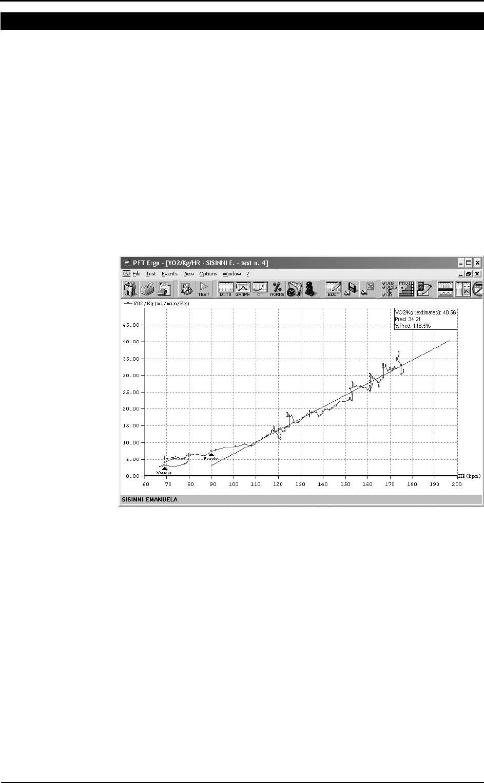
4. Display a VO2/Kg vs. HR plot
5. Right-click on the graph and select VO2 submax from the pop-up menu.
If the predicted HR max (calculated as 220-age) is not suitable for the patient tested, it
is possible to edit the HR max value from the View/Information… page.
An example of testing protocol
An example of protocol is reported here. The YMCA cycle ergometry protocol is
defined as follows.
1st step: workload 150 kgm/min
2nd step: if the HR at the end of the 1st step is: <80 80-89 90-100 >100
set the workload at (kgm/min) 750 600 450 300
3rd step: if the HR at the end of the 2nd step is: <80 80-89 90-100 >100
set the workload at (kgm/min) 900 750 600 450
4th step: if the HR at the end of the 3rd step is: <80 80-89 90-100 >100
set the workload at (kgm/min) 1050 900 750 600

Spirometry

112 - K4 b2 User Manual
Setting spirometry options
The software allows to configure some options selecting Configure from the Option
menu.
Spirometry
Automatic Interpretation
K4 b2 has the function of interpreting each test performed by a patient visualising an
automatic diagnosis. The algorithm has been calculated basing on “Lung Function
Testing: selection of reference values and interpretative strategies, A.R.R.D. 144/
1991:1202-1218”.
The automatic diagnosis is calculated at the end of the FVC Test if:
• the automatic diagnosis option is enabled.
• the patient’s anthropometric data allow the calculation of the LLN (Lower Limit of
Normal range).
• at least one FVC test has been performed.
To enable/disable the automatic diagnosis:
1. Click on Enable Automatic Interpretation checkbox to enable or disable the
calculation and the visualisation of the automatic interpretation.
2. Select the LLN (Lower Limit of Normal Range) criteria among the ATS
(LLN=Pred-0.674*SD), ERS (LLN=Pred-1.647*SD) or 80%Pred (LLN=Pred*0.8)
specifications.
Quality control
K4 b2 allows a quality test control. The calculation has been carried out referring to
“Spirometry in the Lung Health Study: Methods and Quality Control, A.R.R.D. 1991;
143:1215-1223”. The messages concerning the quality control are shown at the end of
the test.
To enable/disable the quality control, click on Enable Quality Control checkbox.
Chapter 10 - Spirometry - 113
Parameters manager
The program allows to calculate a huge number of parameters; it is advisable, in order
to simplify the analysis of the results, to view, to print and to sort the desired parameters
only. Select the menu item Options/Parameters...
View
Move the parameters to view into the Selected parameters list.
Print
Move the parameters to print into the Selected parameters list.
Sort
Drag the parameter up or down with the mouse.
Customise
Add, modify and delete custom parameters.
If it is necessary to restore the default parameters press the button in the left corner of
the window to initialise the parameters database.
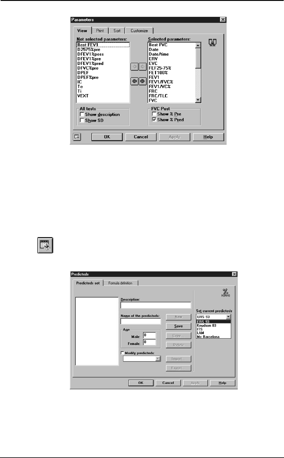
Predicted values manager
The program contains a preset of predicted equations, but the user is allowed to
customise its own predicted sets. Select Predicteds... from Options menu.
The window is divided into two forms: Predicteds set and Formula definition.
Predicteds set
This form allows the user to manage the set of predicteds. The following information
define a set:
114 - K4 b2 User Manual
Name: identifies the set and cannot be duplicated;
Description: free field;
Age: the adult predicteds start since this age.
To enter a new set of predicteds click on the New button. The field Name must be filled
and must be unique. To stop without saving click on the Cancel button. To save the set,
click on the Save button.
To delete a set of predicteds click on the Delete button. If a set is deleted, also the
associated formulae are deleted.
It is possible to generate a new set of predicteds with the same attributes and the same
formulae of the selected one. To do this click on the Copy... button and specify a new
Name.
To import a set of predicteds click on the Import... button and select a file of Predicteds
files type.
To export a set of predicteds click on the Export... button.
In the list Set current predicteds choose the current predicteds for printing and
viewing.
Set the current predicted
K4 b2 allows to calculate the predicted values according to the following configurable
sets:
Adult Paediatric
ERS 93 Zapletal
Knudson83 Knudson83
ITS white ITS white
ITS black ITS black
LAM LAM
MC Barcellona MC Barcellona
Nhanes III Nhanes III
Select the desired choice in the group Predicted.
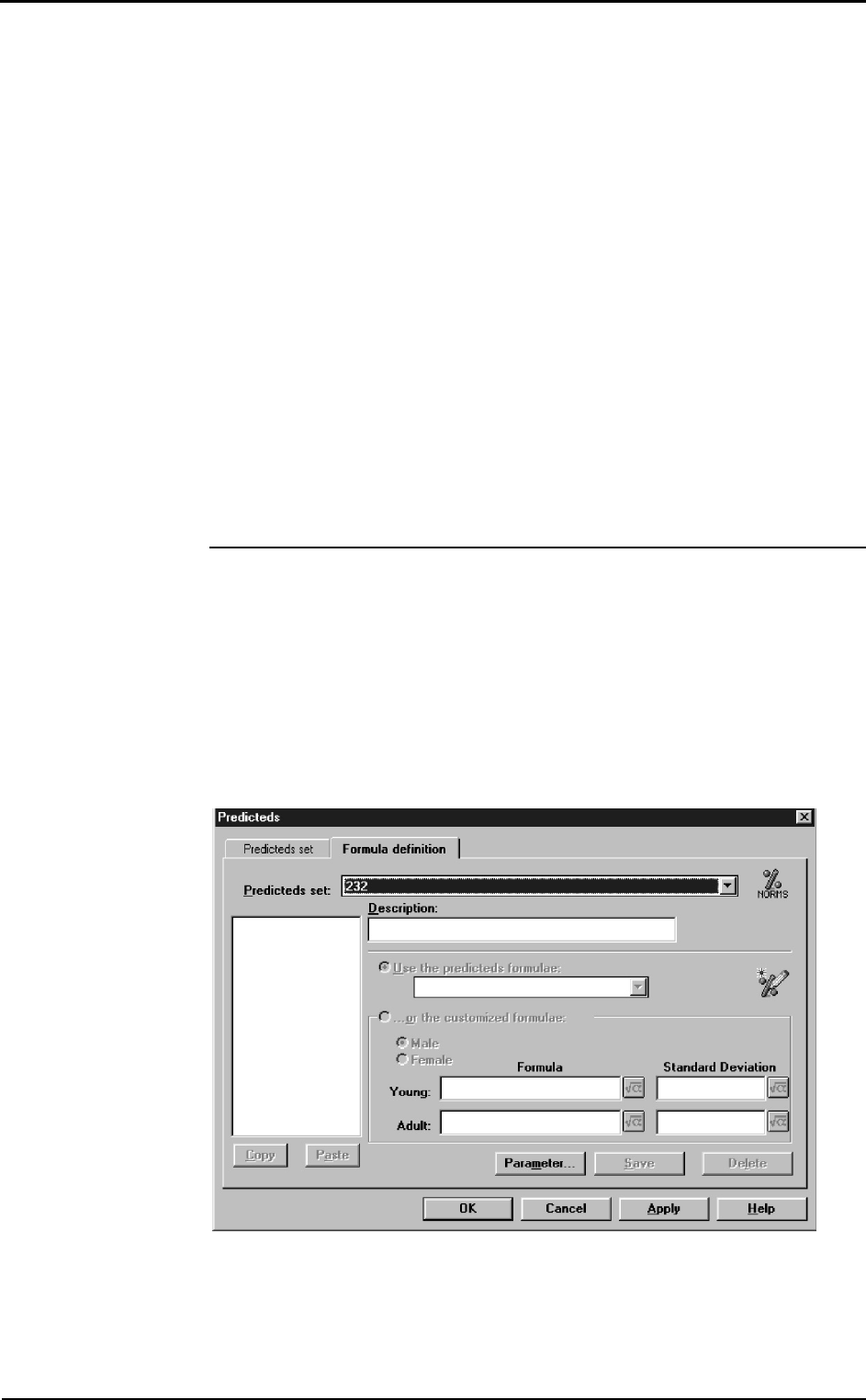
Formula definition
This form allows the user to manage the formulae associated to a set of predicteds.
Select the set of predicteds from the list Predicteds set.
To insert a new parameter click on the New... button.
The parameter formulae can be:
Chapter 10 - Spirometry - 115
• calculated according to the predicteds in the list Use the predicteds formulae;
• customised by the user with the option ...or the customised formulae.
The Delete button deletes the selected parameter.
The Copy button stores the selected parameter in memory.
The Paste button inserts a new parameter from the one copied. If the name is not
unique, the user is asked whether to specify a new name or to replace the existing
parameter.
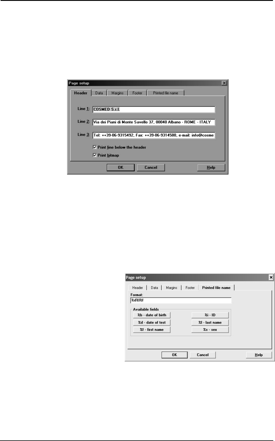
Page set-up
Select Page Setup... from the File menu.
Header All the printouts carried out by the program are preceded by 3
rows of customisable header (usually they contain the name
and the address of the Hospital using the spirometer).
Data Patient and visit information are printed below the header.
These data are reported on 3 columns and 5 rows. the user may
configure the disposition, change and eventually cancel the
fields, as he prefers.
Margins Configures the print margins from the borders of the paper.
The unit of measure is decided in Units of measurements.
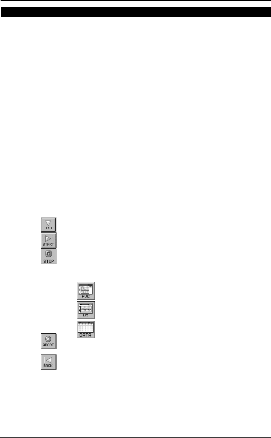
Footer Configures information at the bottom of the page.
Printed file name Defines the automatic name to be asssigned to the pdf file, if
the report will be printed in this format.
In the example it has been set to create a filename composed by
<date of the test> followed by <last name> and <first name>.

116 - K4 b2 User Manual
Spirometry tests
Once completed the phases of the introduction of the patient’s data and the visit data, it
is possible to carry out the spirometric tests.
K4 b2 allows to perform the following tests:
Key Test
FVC pre Forced Vital Capacity
FVC post Forced Vital Capacity after bronchial stimulation
SVC Slow Vital Capacity
MVV Maximum Voluntary Ventilation
Before performing any test make sure that:
1. K4 b2 is properly connected to your PC and the selected serial port (COM1, COM2)
corresponds to the one effectively use.
2. The name shown on the status bar corresponds to the patient who is to carrying out
the tests.
3. The today’s visit card exists.
sss
Note: Read carefully the
contraindications in Chapter 1.
Chapter 10 - Spirometry - 117
Forced Vital Capacity (pre)
FVC is a reference test to verify obstructive (airflow limitations) and restrictive
disorders (lung volume limitations). To achieve good test results it is fundamental a
good manoeuvre (quality control messages, real time plots …)
The main parameters measured during FVC tests are:
FVC Forced Vital Capacity
FEV1 Forced Expiratory Volume in 1 second
FEV1/FVC% FEV1 as a percentage of FVC
PEF Peak Expiratory Flow
FEF25-75% Forced mid-Expiratory Flow
The two representative plots are the Flow/Volume and Volume/Time loops.
By comparing FVC, FEV1 and FEV1/FVC% values the software allows an automatic
interpretation concerning the levels of obstructive and/or restrictive disorders.
Recommendations
• The flowmeter has to be disconnected from the breathing valve
• The patient should wear the nose clips
• The turbine has been recently calibrated (ATS recommends a daily calibration)
• The paper mouthpiece or the antibacterial filter is properly connected to the
flowmeter through the corresponding adapter
For hygienic reasons, we strongly recommend the use of a bacterial filter.
If a kid must perform the test it is recommended to enable the encouragement function
which shows exactly the manoeuvre of the FVC test.
Perform a FVC (pre) test
1. Select Forced Vital Capacity pre from the Test menu and wait for the green led is
prompted on the right side of the screen.
2. Explain the manoeuvre to the patient and press the F2 key.
3. Wait some seconds and perform the test.
4. After having performed the test, press F3 or wait for the automatic end (5 seconds
without flow), so that the software displays the F/V and V/t graphs, the main
parameters, and the predicteds values.
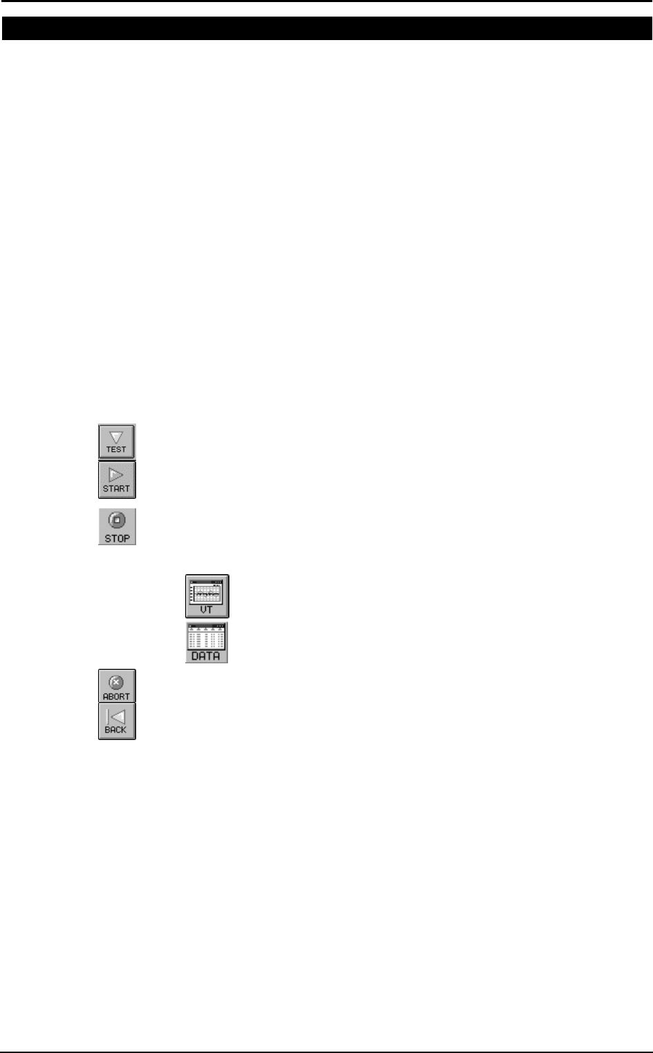
5. In order to visualise the F/V and V/t graph and the main parameters press the
following buttons:
view Flow Volume graph
view Volume Time graph
view data of the test
6. Press Alt+F3 to stop the acquisition discarding the results.
7. Repeat the test until it is correctly performed (ATS recommends 3 times).
8. Press Exit to visualise the test list carried out during current session together with
the results of the main parameters.
9. Select the test that you want to save (the Best Test according to the ATS criteria is
highlighted as default) and press OK.
Test encouragement
During FVC manoeuvre you might experience some lack of collaboration with kids or
with other patients. In this case you may find a good help in using the encouragement
software tool.
118 - K4 b2 User Manual
Perform the FVC test with the encouragement
1. Select Encouragement from View menu.
2. Perform the test as explained in the previous paragraph.
Chapter 10 - Spirometry - 119
Slow Vital Capacity
Important test for assessing COPD (chronic obstructive pulmonary disease) patients
affected by this disease might present a the Slow Vital Capacity could be higher than
the Forced one (FVC).
The main parameters measured during SVC tests are:
EVC Expiratory Slow Vital Capacity
IVC Inspiratory Slow Vital Capacity
ERV Expiratory Reserve Volume
IRV Inspiratory Reserve Volume
If the inspiratory/expiratory maximal manoeuvre is preceded by a some breaths at tidal
volume the software allows to measure the Respiratory Pattern, represented by the
following parameters:
VE Ventilation per minute
Vt Tidal volume
Rf Respiratory frequency
Ttot Breath time
Ti/Ttot Inspiratory time/Ttot
Vt/Ti Vt/Ti
Perform a SVC test
1. Select Slow Vital Capacity from the Test menu and wait for the green led is
prompted on the right side of the screen.
2. Press F2 and instruct the Patient to breath normally until the message “carry out…”
is prompted; then ask to perform a Slow Vital Capacity (deep inhalation, maximal
slow expiration and deep inhalation again).
3. Press F3 or wait for automatic interruption (5 seconds without flow) in order to
visualise the V/t graph together with the main parameters compared to the predicted
values
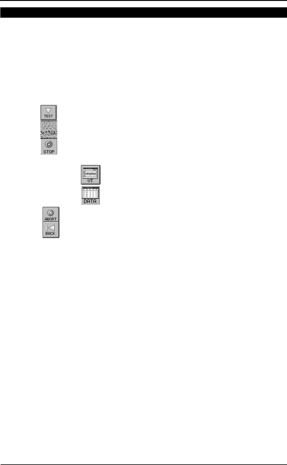
4. To visualise the V/t graph and the main parameters press the follow buttons:
view Volume Time graph
view data of the test
5. Press Alt+F3 to stop the acquisition discarding the results.
6. Repeat the test until it is correctly performed (ATS recommends 3 times).
7. Press Exit to visualise the test list carried out during current session together with
the results of the main parameters.
8. Select the test that you want to save (the Best Test according to the ATS criteria is
highlighted by default) and press OK.
The reference for the ERV calculation is displayed on the V/T graph.
120 - K4 b2 User Manual
Maximum Voluntary Ventilation
Test for assessing the maximum ventilatory capacity. In the past, it was commonly
performed during routine PF tests, however its clinical use declined over the years.
Today MVV test is most commonly performed as part of the exercise tolerance tests,
where it is used as an index of maximum ventilatory capacity. Test consists in breathing
in and out deeply and rapidly for 12, 15 seconds. The expired volume during this short
period is then extrapolated
The most important measured parameter is the following:
MVV Maximum Voluntary Ventilation
Perform a MVV test
1. Select Maximum Voluntary Ventilation from the test menu and wait for the
green led is prompted on the right side of the screen.
2. Press F2 and make the Patient breath as much deeply and rapidly as possible for at
least 12 seconds.
3. Press F3 or wait for automatic interruption (5 seconds without flow) in order to
visualise the V/t graph together with the main parameters compared to the predicted
values
4. To visualise the V/t graph and the main parameters press the follow buttons:
view Volume Time graph
view data of the test
5. Press Alt+F3 to stop the acquisition discarding the results.
6. Repeat the test until it is correctly performed (ATS recommends 3 times).
7. Press Exit to visualise the test list carried out during current session together with
the results of the main parameters.
8. Select the test that you want to save (the Best Test according to the ATS criteria is
highlighted as default) and press OK.

Chapter 10 - Spirometry - 121
Bronchial Provocation Test
Bronchodilator test
Bronchodilators are administered routinely in the b
2 laboratory to determine whether
airflow obstruction is reversible. Bronchodilators increase airway calibre by relaxing
airway smooth muscle.
The test consists of comparing results between the reference FVC (FVC PRE) and the
FVC POST performed after the administration of the drug. Increasing value of 13-15%
of FEV1, respect to the basal value (FVC Pre) is considered as a reversible condition.
Main parameters are the following:
DFEV1%pre Change of FEV1 as a percentage of test PRE
DFVC%pre Change of FVC as a percentage of test PRE
DPEF%pre Change of PEF as a percentage of test PRE
Some authors states that the above mentioned parameters are too dependent from the
FVC Pre, hence latest reference (ERS93, [A comparison of six different ways of
expressing the bronchodilating response in asthma and COPD; reproducibility and
dependence of pre bronchodilator FEV1: E. Dompeling, C.P. van Schayck et Al; ERJ
1992, 5, 975-981]) recommend the following parameters:
DFEV1%pred Change of FVC as a percentage of predicted value
DFEV1%poss Change of FEV1 as a percentage of “possible value”
Methacholine and Histamine Bronchial provocation Tests
The most common indication for performing methacholine and histamine bronchial
challenges is to diagnose hyperresponsive airways. Some patients demonstrate normal
baseline pulmonary function despite complaints of “tightness” wheezing, cough, and a
little or not response to bronchoconstrictor. Other patients demonstrate spirometric
improvement after use of bronchoconstrictor have diurnal variation in peak flows. In
this groups aerosolised bronchial challenges are used to confirm a diagnosis of Asthma.
We can summarise the use of the test as follows:
1. Diagnose asthma
2. Confirm a diagnosis of asthma
3. Document the severity of hyperresponsivness
4. Follow changes in hyperresponsivness
When patients with hyperresponsive airways inhale certain pharmacologic agents (i.e.
Methacholine or histamine) the airways respond by constricting.
Test consists of executing repeated FVC following the pharmacologic agents inhalation
according to an established protocol. The fall of the FEV1 parameter is used to calculate
the bronchial hyperresponsivness. The most important parameter is the PD20 that is
amount of drug (mg/ml) that causes a reduction of 20% of the FEV1 respect the basal
value (without drug).
Main parameters are:
P10 Dose that causes a 10% fall of FEV1.
P15 Dose that causes a 15% fall of FEV1.
P20 Dose that causes a 20% fall of FEV1.
The representative plot is the Dose/response curve, showing the percentage variation of
FEV1 versus the Drug dose in logarithmic scale.
The program assumes as the baseline test the best FVC pre carried out during the
today’s visit. You can change the reference pre test editing the Post test.
The name of the drug, its quantity and its unit of measurement, can be typed
immediately before any FVC post manoeuvre (manual protocol) or can be stored in a
database of bronchoprovocation (File/Bronchial Provocation protocols Database…).
sss
Note: Read carefully the
contraindications in Chapter 1.
122 - K4 b2 User Manual
Perform the test
(During 1st step only) select Protocol... from the Test menu and choose the name of the
bronchoprovocation protocol that you are going to use (manual protocol if you want to
type the information about the agent before any manoeuvre)
1. Select FVC post from the Test menu.
2. Select an existing protocol or click on “manual protocol”, and wait the green leds
turned on.
3. Press F2, or the button by side, to start the test.
4. Press F3, or the button by side, to achieve the test.
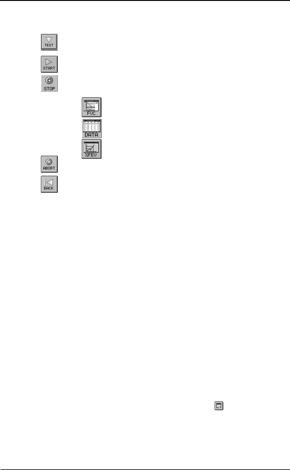
5. In order to visualise the V/t graph and the main parameters press the follow
buttons:
view Flow Volume graph
view data of the test
view bronchial provocation response
6. Press Alt+F3 to stop the acquisition discarding the results.
7. Repeat the test until it is correctly performed (ATS recommends 3 times).
8. Press Exit to visualise the test list carried out during current session together with
the results of the main parameters.
9. Select the test that you want to save (the Best Test according to the ATS criteria is
highlighted as default) and press OK.
Bronchial Provocation protocols Database
The response to a bronchoprovocator is usually assessed in terms of change in the
FEV1, vital capacity or airways resistance on the basis of serial measurements (FVC
manoeuvres) in which the results of the initial test constitute the reference values. The
international literature proposes several standardised protocols in order to address the
methodological issues of the various available techniques.
The possibility to store a bronchoprovocation protocol in a database is useful to simplify
and automate the sequence of operations that the Physician need to execute during the
bronchoprovocation tests.
The typical sequence of activities to carry out a bronchoprovocation test are:
1. Typing and storing a bronchoprovocation protocol in the database (usually only
once).
2. Selection of protocol among the list of the ones already present in the database
before carrying out the FVC post tests (the selection of “manual protocol” allows to
execute the test fully manually).
3. Performing the Post tests.
Enter a new Bronchial provocation protocol in the archive
1. Select Bronchoprov. protocols database from the File menu.
2. Type the Protocol name, the Bronchoprovocator name and the unit of measurement
in the proper input fields.
3. If the bronchoprovocator has a cumulative effect select the cumulative check
button.
4. Enter the quantities for each step and press the button .

Chapter 10 - Spirometry - 123
Viewing results
All the visualisation functions refer to the test carried out by the Current Patient, whose
name is indicated on the left-side of the status bar.
To view tests results:
1. Select the Patients from the File menu
2. Select the patient corresponding to the test you want to view.
3. Select in the list box of the tests up to 5 tests of the kind (FVC, VC/IVC, or MVV)
and press OK.
To switch between graph and or data use the following buttons on the toolbar:
view Flow Volume graph (F5)
view Volume Time graph (F6)
view data of the test (F7)
view bronchial provocation response.
If you need more than one visualisation meantime use the New Window function from
the Window menu.
If you need to display a list of visits:
• Select Visits list... from the File menu.
• Type the name of the Company and/or the time interval desired or simply confirm
for the complete list.
Tests of the current patient
If a current patient has been selected you can quickly view his tests selecting Test
current patient... from the View menu.
Delete a test
1. Select Patients from the File menu or press the button by side.
2. Select the test that you want to eliminate from the list of the tests referred to the
Current Patient and press Delete.

124 - K4 b2 User Manual
Printing results
You can print out in three different ways:
• printing the Report
• printing the Active Window
• printing a series of reports
Printing Reports
To print a report of the current visit, select Print report… from File menu. The
software will choose automatically the best performed test.
The standard Report is composed by 1, 2 or 3 pages depending if you wish to printout
the FVC data and the graphs together on the first page or if you wish to printout the
bronchoprovocation response.
• Selecting the option One page (no ATS) the report will contain, on one page, the
F/V and V/t graphs of the best test, overlapped on the FVC Post, the patient data,
the notes, the diagnosis and the test results.
• Otherwise the report will contain two pages, the first with the patient data, the
graphs and the diagnosis, and the second one with the measured parameters,
according to the ATS recommendations.
• The 3rd page will contain the bronchoprovocation response.
Select the desired options:
FVC graph Prints the F/V and V/t curves for the best FVC test.
One page (no ATS) Prints data and graphs on the first page.
Response Prints the bronchoprovocator response.
Preview Views a report preview on the screen.
Printing the active window
This printout function is only enabled when the active window (title bar highlighted) is
one of the following objects:
• Any kind of Graph.
• Numeric data
• List of visit
To print the active window
1. Ensure that the active window is one of the preceding objects.
2. Select Print Active window from File menu.
Printing a series of reports
Sometimes it is useful to printout automatically a series of reports (all tests carried out
with the employees, all tests carried out in the today's session).
To print out proceed as follows:
1. Select Visit List from the File menu
2. Set the criteria of the visits to be added in the list (from, to,...)
3. Select Print Report from the File menu.
Electronic reports (*.pdf)
If an Adobe PDF writer “Printer Driver” is installed and set as the default printer, it is
possible to store the printout report automatically in any location of the HD or
eventually LAN paths according to a customizable filename format.
It is possible to define the created filename format selecting File/Page Set up... (see
Page set-up).

Chapter 10 - Spirometry - 125
Export data
With this function you can export the test data in 4 different formats:
• *.txt (ASCII)
• *.xls (Microsoft Excel)
• *.wk1 (Lotus 123)
• *.xpo (Cosmed)
Export a test
1. Select Export tests from the File menu.
2. Select the test to export from the list box and press OK.
3. Type the name and the format of the file in the dialog Save as. If the ASCII format
is selected, the Text button in the dialog box Save as allows you to configure the
separators for character based files.
With the *.xpo Cosmed file format it is possible to import data from another K4 b2
archive. Press OK to confirm.
4. Select the folder for the export and type the file name. Press OK to confirm. A
status bar will show the file creation.

126 - K4 b2 User Manual

External devices

128 - K4 b2 User Manual
GPS
GPS initialisation
The GPS operates on information gathered from satellites.To gather this information,
take your GPS on outside and find large, open area that has a clear view of the sky (a
nearby park would work fine). The GPS needs to receive at least three strong satellite
signals to find your location.
At the first power on the GPS needs to be initialized; the initialisation is a fundamental
procedure for obtaining accurate and reliable data and should be performed on a large
area where the sky is fully "visible".
After the initial self test is complete, the GPS will begin the process of satellite
acquisition and tracking. The acquisition process is fully automatic and, under normal
circumstances, will take approximately 45 seconds to achieve a position fix (15 seconds
if ephemeris data is known).
Like all GPS receivers, COSMED GPS utilizes initial data such as last stored position,
date and time as well as satellite orbital data to achieve maximum acquisition
performance. If significant inaccuracy exists in the initial data, or if the orbital data is
obsolete, it may take 5.0 minutes to achieve a navigation solution. The GPS
Autolocate™ feature is capable of automatically determining a navigation solution
without intervention from the user. This procedure may be required if one of the
following situations occurs:
1) Transportation over distances further than 1500 kilometers.
2) Failure of the internal memory battery without system standby power.
3) Stored date/time off by more than 30 minutes.
The GPS will automatically update satellite orbital data as it operates. The intelligence
of the GPS combined with its hardware capability allows these data to be collected and
stored without intervention from the host system.
Initialize the GPS
1) If the receiver is not operated for a period of six (6) months or more, the unit will
“search the sky” in order to collect satellite orbital information. This process is
fully automatic and, under normal circumstances, will take 3-4 minutes to achieve a
navigation solution.
2) If the memory backup battery of the GPS fails, the receiver will search the sky as
described above. Should the memory battery discharge, the unit needs to be
powered on for several hours to insure a sufficient recharge to maintain several
months of clock operation and memory storage.
3) If the initial data is significantly inaccurate, the receiver perform an operation
known as AutoLocate™ . This procedure is fully automatic and, under normal
circumstances, will require 1.5 minutes to calculate a navigation solution.
During the acquisition process a message "acquiring satellites...." is prompted on the
display of the Portable unit.
The AutoLocate™ function can be manually forced selecting GPS AutoLocate from
the Calibration menu, in order to obtain the best accuracy.
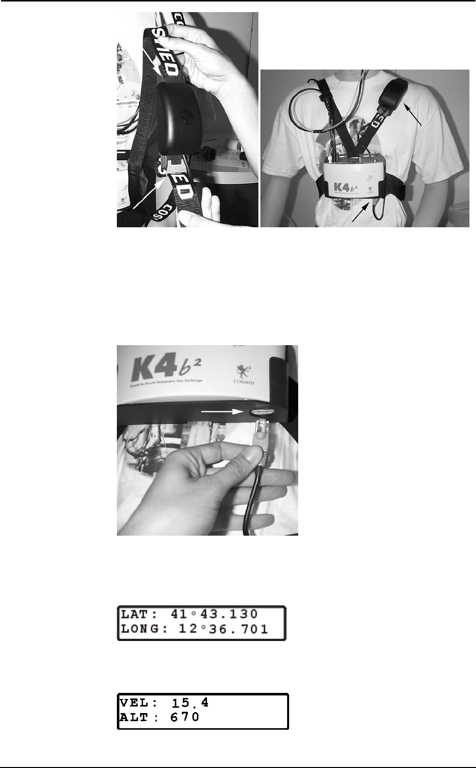
Fixing the antenna to the subject
The GPS Receiver has to be positioned onto the harness of the K4b2 according the
following pictures, paying attention to keep the receiver in a position so that the sky will
be always "visible" during the test.
Some applications such as cycle racing and rowing may require different positioning of
the antenna.
Chapter 11 - External devices - 129
Operating sequence
Test with GPS module can be carried out with K4 b2 system in Holter Data Record or
Telemetry Data Transmission mode only. In addition to the Operating sequence of this
mode you must carry out the following operation.
Run a test with GPS
1. Connect the receiver antenna to the Portable Unit plugging phone jack into the
RS232 port at the bottom of the PU.
2. Select Settings then External device and press Enter.
3. Enable the GPS option by moving the “*” sign on GPS and press Enter to confirm
settings.
4. Check the GPS module functionality choosing Calibration then GPS Control and
press Enter. Display will show latitude and longitude.
5. With the use of Up and Down key verify that the displayed altitude value (Alt) is
different from zero. In case displayed altitude value is fixed on zero, please be sure
that the antenna receiver is well plugged in, the “sky” is visible and wait until the
Altitude value is shown.

130 - K4 b2 User Manual
Monitoring GPS parameters in real time
To monitor in real time GPS parameters during Telemetry Mode Transmission or as
soon as test has been stored or downloaded, go to the PC software and select
Parameters to view/Test execution… (real time) or Parameters to view/Test
visualization… (after download) from the Options menu.
Select the following parameters:
Velocity GPS Vel (m/sec)
Distance GPS Dist (meters, incremented during exercise phases only)
Latitude Lat (DD°MM.MMM’ N/S)
Longitude Long (DD° MM.MMM’ E/W)
Altitude Alt (meters)
Only when test has been stored or downloaded you can verify the Graphical path
(automatically drawn on a scaled X/Y plane oriented to North ) selecting on the PC
software Visualization and GPS track.
Note: Distance is automatically calculated only during the "exercise" phases.

Chapter 11 - External devices - 131
Pulse Oximeter (option)
The oximeter option is useful to monitor SpO2 value during the test. Test with this
option can be carried out with K4b2 system in Holter Data Record or Telemetry Data
Transmission mode only.
In addition to the Operating sequence of this mode you must carry out the following
operation:
Operating Sequence
1. Connect the Oximeter module to the Portable Unit plugging phone jack into the
RS232 port at the bottom of the PU
2. Go to the K4b2 control panel and select Oximeter like External device connected by
choosing Settings than External device and press Enter
3. Enable the Oximeter option by moving the “*” sign on Oximeter and press Enter
to confirm settings.
4. Positioning Finger or Ear Clip on the patient and fix well the cable with Velcro
stripes on the harness to minimize motion artifact
To monitoring in real time SpO2 value during Telemetry Mode Transmission or as soon
as test has been stored or downloaded, go to the PC software, select Parameters to
view/Test execution… (real time) or Parameters to view/Test visualization… (after
download) from the Options menu and select SpO2 parameter.

132 - K4 b2 User Manual

System
maintenance

134 - K4 b2 User Manual
System maintenance
All service operations which are not specified in this user manual should be performed
by qualified personnel in accordance with the service handbook (to be required to the
manufacturer).
Rubber mouthpieces, face masks, breathing valve and the other parts are not shipped
sterile. They should be disinfected before using according to the following instructions.
All materials used in the construction of the K4 b2 are non toxic and pose no safety risk
to the patient or operator.
Prior to the device cleaning, disinfection and inspection it is necessary to switch off the
device and to disconnect adapters from the supply mains.
In order to guarantee the highest accuracy of measurements we recommend you to
disinfect the turbine periodically.
Use disposable anti-bacterial filters or disinfect each part in contact with the patient
before each test.
Cleaning and disinfection
Cleaning and disinfecting instructions are of fundamental importance to control
infections and assure patient safety. In fact aspiration of residue, particles and
contaminated agents are life – threatening.
In this handbook we strongly recommend you to follow the rules worked out by ATS
and ERS (see: ”Lung Volume Equipment and Infection Control” – ERS/ATS
WORKSHOP REPORT SERIES, European Respiratory Journal 1997; 10: 1928 –
1932), which are summarised as follows:
• Accessible internal as well as external surfaces of equipment exposed to expired
gas should be washed and disinfected prior to testing of subsequent patients.
• Liquid disinfection can be used if the equipment is well cleaned first (no droplets of
saliva/sputum remain).
• Disposable gloves should be worn when handling mouthpieces, when cleaning
equipment exposed to saliva or sputum and especially when drawing blood.
• Laboratory staff should wash hands prior to testing of each patient.
• Adopt particular precautions when testing patients with recognised high – risk
communicable diseases (e.g. tuberculosis, multidrug – resistant staphylococcus). In
these cases, the clinical need for such testing should justify the risks.
During the disinfection:
• do not use alcohol or other liquids containing gluteraldehyde on the exterior
surfaces of the equipment. Actually they can damage polycarbonates plastics and
may produce unhealthy substances.
• do not use abrasive powders or glass cleaners containing alcohol or ammonia on the
plexiglas components of the equipment
• do not steam autoclave any parts of the equipment unless it is clearly specified.
• do not immerse the optoelectronic reader.
Preparing the disinfecting solution
The following recommendations are retrieved from:
APIC (Association for Professionals in Infection Control and Epidemiology, Inc.):
APIC Guidelines for Selection and Use of Disinfectants; William A. Rutala, PhD, MPH,
CIC. American Journal of Infection Control, vol.24, N.4, pp. 313-342, August 1996 -
http://www.apic.org/pdf/gddisinf.pdf
As disinfecting solution it is suggested:
• Sodium hypochlorite 0.5% (5000 ppm) prepared fresh for use within 24 hours.
• Sodium hypochlorite 1% (10000 ppm) prepared fresh for use within 30 days.
The first solution can be easily prepared by adding 1 part household bleach (sodium
hypochlorite 5.25%) to 9 parts water, the second one by adding 1 part household bleach
to 4 parts water.
Chapter 12 - System maintenance - 135
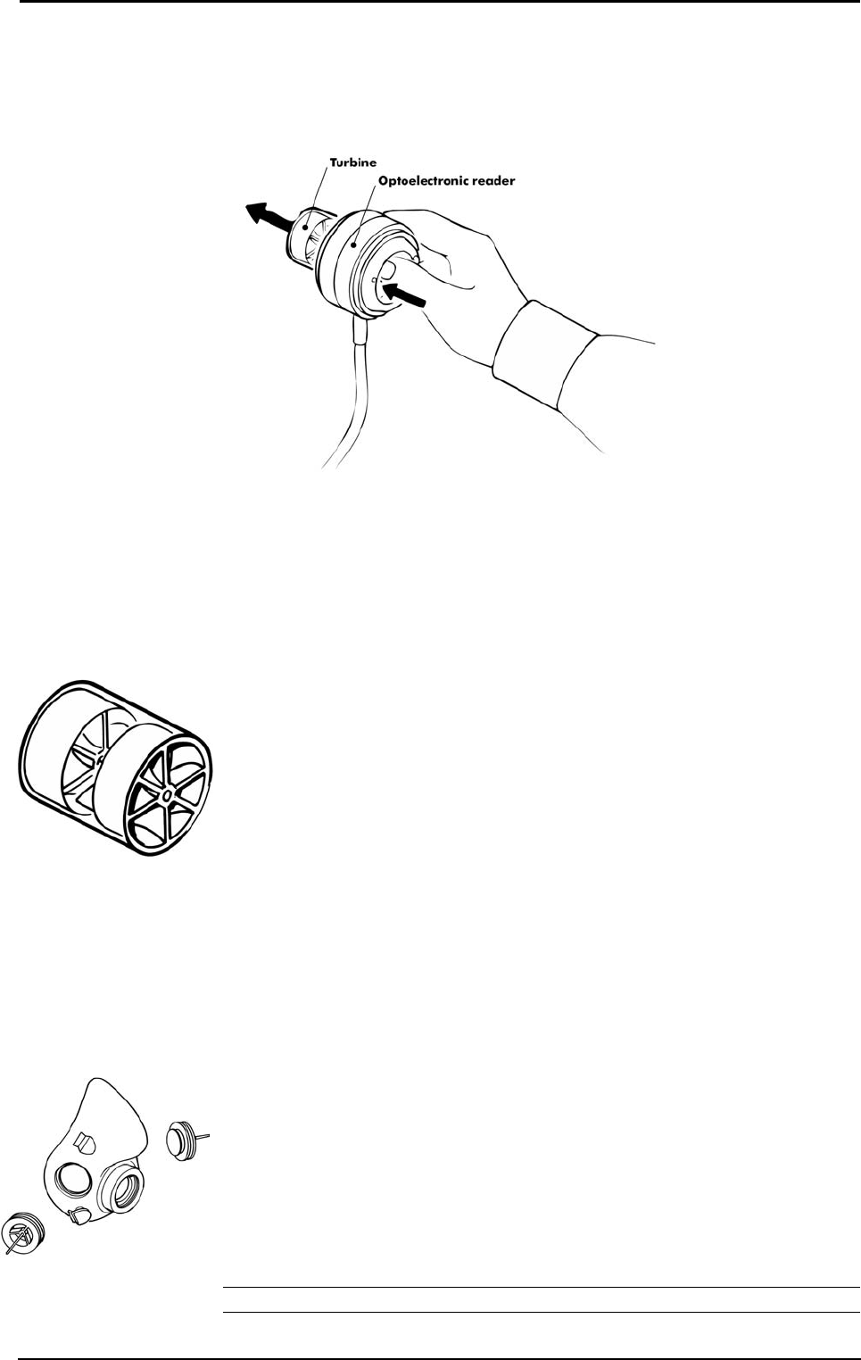
Cleaning the turbine flowmeter
It is necessary to disinfect periodically the turbine for sanitary measures or/and for the
correct device function.
The disinfecting procedure is easy and may be effected every time the user needs,
keeping attention to some precautions:
1. Take out the turbine.
2. Dip it in a disinfectant solution (non alcoholic based) for about 20 minutes.
3. Rinse the turbine in a vessel, filled of clean water, shaking gently to remove the
disinfectant (do not clean the turbine by putting it under running water!).
4. Let it dry to air.
5. After cleaning the turbine, check if the turbine propeller rotates freely even with a
low speed air flow.
6. Connect the turbine to the reader.
Precautions during the cleaning of the turbine
1. Do not expose the turbine to high heat and do not put it under running water.
2. Do not ever dip the optoelectronic reader in any kind of solution, the liquid
infiltration would damage the internal circuit.
3. Do not use alcoholic solutions to clean the turbine.
Suggested disinfection solutions
Helipur H Plus Braun Melsungen AG
Gigasept FF Schulke & Mayr GmbH
Dismozon pur Bode Chemie GmbH
TETA-S Fresenius AG
CIDEX Johnson & Johnson
Masks cleaning and disinfection
The face masks should be cleaned and sterilised after each test.
Disassembling the different parts of the mask
1. Remove the valves from their place.
2. Remove the adapter for the optoelectronic reader.
Cleaning the mask
1. Clean the mask with hot water and a soap solution to remove the impurities.
2. Rinse the mask with energy in running hot water.
Warning: Do not use synthetic or petroleum-based products for the masks cleaning.
sss
Warning: Do not use
alcoholic solutions for the
turbine, otherwise there can
be damages to the plastic
material.

136 - K4 b2 User Manual
Disinfecting the mask
It’s possible disinfecting the mask following these procedures:
• Standard autoclaving method
Rapid cycles of autoclave lasting 10 minutes at 132°C (270°F)
Heavy cycles of autoclave lasting 30 minutes at 121°C (250°F)
Pre vacuum cycles of autoclave lasting 30 minutes at 121°C (250°F)
• Hetilene oxide method (ETO)
The hetilene oxide doesn’t deteriorate the face masks. Sterilisation by this method
is not advised unless sufficient data is available regarding the time required for
complete out-gassing of residual ETO. If you use this method, follow carefully the
instruction provided by the maker of the sterilising product.
• Pasteurisation
The disinfecting with hot water is a sterilising method that may be used with the
silicone masks.
Permapure maintenance
• Do not bend, squash or deform it.
• Do not keep it in open air, if not used, especially in crowded or smoky places.
• If saliva is entered in the tube, replace it immediately, because it lost its functions.
• Periodically grease the o-ring on the connector in order to simplify the flowmeter
connection.
• Replace it every 100 test / 6 month.
Inspections
The equipment requires easy inspections to be carried out in order to assure a proper
electrical and mechanical safety level in the years.
These inspections are highly recommended after a rough use of the equipment or after a
period of storage in unfavourable environmental conditions.
Referring to the electrical safety, it is important to check the conditions of insulation
materials of cables, plugs and any other visible part by means of simple inspection,
when the equipment is switched off and adapters (or electrical feeders) are disconnected
from the supply mains.
Mechanical parts to check are: the turbine and breathing circuits.
Follow these instructions:
• extract the turbine from the optoelectronic reader;
• verify, by inspection, that the turbine axis fits correctly its seats and the blade is
strongly fastened on the axis itself (it can be useful to shake slightly the turbine in
order to note any anomalous movement).
Check if there are any torn or broken components in the breathing circuits: remember
that they can create safety risk to patients during tests.
Replace the fuses
The fuses can be replaced easily in the following way:
1. Open the power supply cover using a screwdriver as shown in the picture.
2. Extract the fuse holder as shown in the picture

Chapter 12 - System maintenance - 137
3. Replace the damaged fuse(s).
Note: Be careful to use proper fuses:
A 680 023 500 (Time lag fuses 5x20 250V T500mA)

138 - K4 b2 User Manual

Appendix

140 - K4 b2 User Manual
Service - Warranty
Warranty and limitation of liability
COSMED provides a one (1) year limited warranty from the date of the original sale of
COSMED products. All COSMED products are guaranteed to be free from defect upon
shipment. COSMED’s liability for products covered by this warranty is limited
exclusively to replacement, repair, or issuance of a credit for the cost of a defective
product, at the sole discretion of COSMED. COSMED shall not be liable under the
foregoing warranty unless (i) COSMED is promptly notified in writing by Buyer upon
discovery of defect; (ii) the defective product is returned to COSMED, transportation
charges prepaid by Buyer, (iii) the defective product is received by COSMED no later
than four weeks after the last day of the one (1) year limited warranty period; and
(iv) COSMED’s examination of the defective product establishes, to COSMED’s
exclusive satisfaction, that such defect was not caused by misuse, neglect, improper
installation, unauthorised repair or alteration, or accident. If the product is
manufactured by a third-party, COSMED shall make available for the Buyer’s benefit
only those warranties which COSMED has received from the third-party
manufacturer(s). COSMED hereby specifically disclaims any and all warranties and/or
liabilities arising from defect(s) and/or damage(s) to and/or caused by products
manufactured by third-party manufacturers. Buyer must obtain written authorisation
from COSMED prior to the repair or alteration of COSMED products(s). Failure of
Buyer to obtain such written authorisation shall void this warranty.
COSMED hereby specifically disclaims any and all other warranties of any kind,
whether express or implied, in fact or by law, including, but without limitation, any and
all warranties of merchantability and/or fitness for a particular purpose.
COSMED shall not be liable for special, indirect and/or consequential damages, nor for
damages of any kind arising from the use of any COSMED’s products, whether said
products are used alone or in combination with other products or substances.
Determination of the suitability of any of COSMED’s product(s) furnished hereunder
for the use contemplated by Buyer is the sole risk and responsibility of Buyer, and
COSMED has no responsibility in connection therewith. Buyer assumes all risks and
liabilities for loss, damage or injury to persons or property of Buyer or others arising out
of the use or possession of COSMED’s products.
The limited warranty as herein above set forth shall not be enlarged, diminished,
modified or affected by, and no obligation or liability shall arise or grow out of, the
renderings of technical advice or service by COSMED, its agents or employees in
connection with Buyer’s order or use of the product(s) furnished hereunder.
Return goods policy for warranty or non warranty repair
Goods shipped to COSMED for repair are subject to the following conditions:
1. Goods may only be returned after your receipt of a Service Return Number
(SRN) from COSMED S.r.l.
2. Place your SRN report and Packing List outside the package.
3. Goods returned must be shipped with freight and insurance charges prepaid.
Collect shipments will not be accepted.
4. The following list of goods are not eligible for return unless proven defective.
- Special order items
- Expendable products
- Goods held over 30 days from COSMED’s invoice date.
- Used goods not in original shipping containers.
- Goods which have been altered or abused in any way.
5. The following parts are not covered by warranty:
- consumables
- fragile glass or plastic parts
- rechargeable batteries
- damages at the
- damages due to use of the device not conforming to the indication reported in this
manual

Chapter 13 - Appendix - 141
Repair Service Policy
Goods returned to seller for Non-Warranty repair will be subject to conditions 1, 2, 3, 4.
The returned goods need to re-enter COSMED together with the customs documents
(Pro-forma Invoice and Customs Paper) as requested by the Italian law.
• The shipment has to be qualified as a Temporary Export.
• All the goods returned to COSMED without the customs papers will not be
accepted.
For European Community members:
Pro-Forma invoice complete with:
• Number
• Description of the goods
• Quantity
• Serial Number
• Value in €
• Number of parcel
• Gross weight
• Net weight
• Reason for resent (i.e. Resent for repair)
In case you should send the system for repair please contact the nearest service centre or
contact COSMED at the following address:
COSMED S.r.l.
Via dei Piani di Monte Savello 37
P.O. Box 3
00040 Pavona di Albano - Rome, Italy
tel. +39 (06) 9315492
fax +39 (06) 9314580
E-mail: customersupport@cosmed.it
For USA customers only please contact:
COSMED USA Inc
2758 North Paulina
Chicago IL 60614 USA
Phone: +1 (773) 528-8113
Fax: +1 (773) 528-8116
email: usa.sales@cosmed.it
To ensure that you receive efficient technical assistance, please specify as precisely as
possible the nature of the problem as it is specified on the assistance information form.
We advise you to save the original packaging. You may need it in case to ship the unit
to a technical assistance centre.

142 - K4 b2 User Manual
Privacy Information
Dear Customer,
we inform you that your personal data are gathered and will be used by Cosmed Srl in
conformity with the requirements of the Italian privacy law (Decreto Legislativo
196/2003). We believe it is important for you to know how we treat your personal data.
Personal data treatment and purposes
We request and process your personal data:
a. to place an order, register a product, request a service, answer a survey, enter a
contest, correspond with us (all of the above, in the following: “service”) and, if
necessary, to supply the Competent Authorities with the required information;
b. in order to define your commercial profile;
c. in order to use your commercial profile for own marketing and advertising
purposes;
d. for accounting purposes, including e-mailing of commercial invoices;
e. for providing your information to selected business partners (also abroad), in order
to supply the service;
How your personal data are treated
Your personal data will be stored in electronic format, and protected at the best from
destruction, loss (even accidental), not authorized accesses, not allowed treatment or use
not in conformity with the purposes above listed.
The consent is optional, but…
If you deny the consent, we regret we cannot supply the service.
Holder of the treatment
The holder of the treatment is Cosmed Srl, Via dei Piani di Monte Savello 37, Pavona di
Albano Laziale (RM). The responsible of the personal data treatment is indicated in the
documentation stored by Cosmed Srl itself.
Customer rights
In accordance with art.7 of the Law, you can:
a. obtain confirmation of the existence of your personal data and their communication
in intelligible form;
b. obtain:
• updating, correction or integration of your data;
• deletion or transformation in anonymous form of your personal data;
c. deny your consent to the treatment of your personal data;
These rights can be exercised directly requesting in writing to the holder of the
treatment.

Chapter 13 - Appendix - 143
Converting factors configuration
You can edit the parameters shown in Control Panel by selecting Control Panel from
the Calibration menu in the calibration program, then pressing the button by side.
You might configure the following options:
Name: identify the parameter
Unit of meas.: unit of measurement
Base line and Gain: factors used to convert the acquired raw data (mV) into the final
format according to Y=(mV-BL)*Gain. The value entered for
gain must be multiplied by 1000 (for Gain=1, enter 1000).
Precision: the number of decimals shown as 0
144 - K4 b2 User Manual
Calculations references
VO2 and VCO2
"Energy Expenditure and Fuel Selection in Biological Systems: The Theory and
Practice of Calculations Based on Indirect Calorimetry and Tracer Methods": M. Elia,
G. Livesey, World Rev. Nutr. Diet. Basel, Karger, 1992, vol 70, pp 68-131.
"Nutritional Assessment in Critical Care, A Training Handbook": Donald C. Zavala
Anaerobic threshold (modified V-Slope)
The break-point or intercept of the two slopes can be selected by a computer program
that defines the VO2 above which VCO2 increases faster than VO2, without
hyperventilation.
During an incremental exercise above the Lactate Threshold, the net increase in lactic
acid production results in an acceleration of the rate of increase in VCO2 relative to
VO2. When these variables are plotted against each other (squared graph without
recovery points), the relationship is composed of two apparently linear components, the
lower of which has a slope of slightly less than 1.0, whereas the upper component has a
slope steeper than 1.0. The intercept of these two slopes is the LT or AT point measured
by gas exchange.
The increase in VCO2 in excess of that derived from aerobic metabolism must be
generated from the buffering of lactic acid. This is an obligatory gas exchange
phenomenon seen in all subjects who exercise to work levels above their LT. This
technique is referred to as the V-Slope method.
OVS, Original V-Slope method: "A new method for detecting anaerobic threshold by
gas exchange", Beaver, Wasswrman, Whipp, JAP 1986, 60:2020-2027.
MVS, Modified V-Slope method: "Metabolic acidosis during exercise in patients with
chronic obstructive pulmonary disease", Sue, Wasserman, CHEST 1988, 94:931-938.
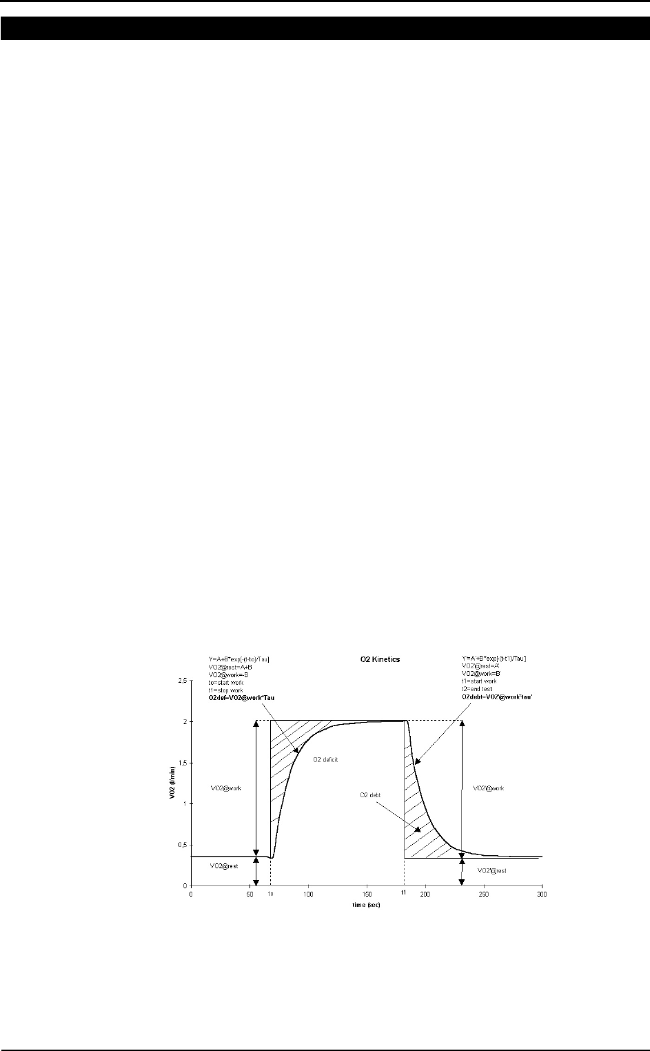
O2 kinetics
“Delayed Kinetics of VO2 in the Transition from prior Exercise. Evidence for O2
Transport Limitation of VO2 Kinetics: A Review”; R.L. Hughson and M.A. Morrissey,
Int. J. Sports Med. 4 (1983) 31-39
ISO 8996: Ergonomics – Determination of metabolic heat production, 1990
In the following picture it is shown how the O2 debit and deficit values are computed.

Chapter 13 - Appendix - 145
ATS 94 recommendations
Reference: “Standardization of Spirometry: 1994 Update” “American J. Respiratory
Critical Care Medicine”, Vol. 152, 1107-1136; 1995.
ATS recommendations
Volume range: 8l (BTPS)
Flow range: ±14 l/sec
Volume accuracy: ±3% or < 50ml
Flow accuracy: ±5% or < 200ml/sec
Flowmeter resistance: <1.5 cmH2O da 0 a 14 l/sec
Reproducibility: the 2 largest of 3 acceptable FEV1 and FVC values should be within
5% or 150 ml.
The end of test: no change in volume for 1 second with at least 6 seconds of collected
volume.
Accumulation time: the maximum time allowed for volume accumulation during the
VC manoeuvre should be at least 30 seconds and at least 15 seconds during the FVC.
The spirometer should be store at least 8 FVC maneuvres.
FEV1 should be calculated by using the “back extrapolation” method to detect the start
of the test, extrapolated volume must not be higher then 5% FVC or 150ml.
The graphic resolution of the printed report must be as in the following:
Volume: 10 mm/l
Flow: 5 mm/l/sec
Time: 20 mm/sec
F/V ratio: 2:1
The total number of error (FVC e FEV1 >±3.5%, FEF25-75% >5.5%) during the
measurement of the 24 standard waveforms must be lower than 4.

146 - K4 b2 User Manual
Predicted values
ERS93
Standardized Lung Function Testing: Official Statement of the European Respiratory
Society, The European Respiratory Journal Volume 6, Supplement 16, March 1993.
Compilation of reference values for lung function measurements in children: Ph. H.
Quanjer, J. Stocks, G.Polgar, M. Wise, J. Karlberg, G. Borsboom; ERJ 1989, 2,
Supp.4,184s-261s.
KNUDSON 83
Changes in the Normal Maximal Expiratory Flow-Volume Curve with Growth and
Anging: J. Knudson, D. Lebowitz, J. Holdberg, B. Burrows; ARRD 1983; 127:725-734
ITS
Intermountain Thoracic Society: Clinical Pulmonary Function Testing, second edition
(1984) pp 101, 144
LAM
A survey of ventilatory capacity in Chinese subjects in Hong Kong: Lam Kwok-Kwong,
Pang Shing et Al. Annals of Human Biology, 1982, vol. 9, No. 5, 459-472.
Multicéntrico de Barcelona
Spirometric reference values from a Mediterranean population: J. Roca, J. Sanchis, A.
Agusti-Vidal, F. Segarra, D. Navajas. R. Rodriguez-Roisin, P. Casan, S. Sans. Bull. Eur.
Physiopathol. Respir. 1986, 22, 217-224.
Nhanes III
Spirometric reference values from a sample of the general US population: John L.
Hankinson, John. R. Odencrantz and Kathleen B. Fedan. Am J Respir Critr Care Med
1999, 159, 1798-187.
Pneumobil (Brazil)
Valores extraìdos do Programa Pneumobil/Brasil para a Tese de Doutoramento do Dr.
Carlos Alberto de Castro Pereira. (Boehringer).
Gutierrez (Chile)
Gutierrez et Al. Reference values for Chile population
Knudson, Morris and Bass
The maximal Expiratory Flow-Volume curve: Knudson et al. ARRD Vol. 123, p. 659-
664, 1981
Spirometric Standard for healthy non-smoking adults: ARRD Vol. 10-3, p. 57-67, 1971
Pereira (Brazil)
Pereira CAC; Barreto SP; Simões JG; Pereira FWL; Gerstler JG; Nakatani J. Valores de
Referência para Espirometria em uma amostra da população brasileira adulta. Jornal de
Pneumologia 1992; 18: 10-22.
Mallozi MC. Valores de referência para espirometria em crianças e adolescentes,
calculados a partir de uma amostra da cidade de São Paulo. Valores finais publicados
em : Pereira CAC; Lemle A; Algranti E; Jansen JM; Valença LM; Nery LE; Mallozi
M; Gerbasi M; Dias RM; Zim W. I Consenso Brasileiro sobre Espirometria. Jornal de
Pneumologia 1996; 22:105-164.
Scalambrini Costa F, Scueiri CEB, Silva Jr WC, Pereira CAC, Nakatani J. Valores de
referência para espirometria em uma amostra da população brasileira adulta da raça
negra. J Pneumologia 1996;22: 165-170.
Neder JA; Andreoni S; Castelo-Filho A; Nery LE. Reference values for lung function
tests. I. Static Volumes. Brazilian Journal Medical and Biological Research 1999;
32:703-17.
Neder JA, Andreoni S, Lerario MC, Nery LE. Reference values for lung function tests.
II. Maximal respiratory pressures and voluntary ventilation. Braz J Med Biol Res 1999
;32:719-27
DLCO
Standardized Lung Function Testing: Official Statement of the European Respiratory
Society, The European Respiratory Journal Volume 6, Supplement 16, March 1993.

Chapter 13 - Appendix - 147
Compilation of reference values for lung function measurements in children: Ph. H.
Quanjer, J. Stocks, G.Polgar, M. Wise, J. Karlberg, G. Borsboom; ERJ 1989, 2,
Supp.4,184s-261s.
Reference Values for Residual Volume, Functional Residual Capacity and Total Lung
Capacity - ATS workshop on Lung Volume measurements, official statement of the
European Respiratory Society; J. Stocks, Ph. H. Quanjer: ERJ, 1995, 8, 492-506
Single Breath Oxygen Test
Buist SA, Ross BB: Quantitative Analysis of the Alveolar Plateau in the Diagnosis of
Early Airway Obstruction. ARRD 108: 1081, 1973
Mansell A, Bryan C, Levison H: Airway Closure in Children. JAP 33: 711-714, 1972
Buist SA, Ross BB: Predicted Values for Closing Volumes Using a Modified Single
Breath Test. ARRD 107: 744-751, 1973.
Rint
Lombardi E, Sly PD, Concutelli G, et al. Reference values of interrupter respiratory
resistance in healthy preschool white children. Thorax 2001; 56: 691-695.
Mip/Mep
Leo F. Black, Robert E. Hyatt: Maximal Respiratory Pressures: Normal Values and
Relationship to Age and Sex, American Review of Respiratory Disease, Volume 99,
1969
Vincken W, Ghezzo H & Cosio MG (1987). Maximal static respiratory pressures in
adults: normal values and their relationship to determinants of respiratory function. Bull
Eur Physiopathol Resp 23: 435-439.
Automatic diagnosis (algorithm)
Reference: “Lung Function Testing: selection of reference values and interpretative
strategies”, A.R.R.D., 144/ 1991:1202-1218.
LLN=Pred-0.674*SD (ATS, 50° percentile)
LLN=Pred-1.647*SD (ERS, 95° percentile)
LLN=Pred*0.8 (80%Pred)
Message interpretation Criterion
Normal Spirometry FVC and FEV1/FVC > LLN
Obstructive abnormality (it may be physiological) % Pred FEV1 >= 100
Obstructive abnormality: mild % Pred FEV1 < 100 and >= 70
Obstructive abnormality: moderate % Pred FEV1 < 70 and >= 60
Obstructive abnormality: moderately severe % Pred FEV1 < 60 and >= 50
Obstructive abnormality: severe % Pred FEV1 < 50 and >= 34
Obstructive abnormality: very severe % Pred FEV1 < 34
Restrictive abnormality: mild FVC < LLN and % Pred FVC >= 70
Restrictive abnormality: moderate % Pred FVC < 70 and >= 60
Restrictive abnormality: moderately severe % Pred FVC < 60 and >= 50
Restrictive abnormality: severe % Pred FVC < 50 and >= 34
Restrictive abnormality: very severe % Pred FVC < 34
Quality Control Messages
Reference: Spirometry in the Lung Health Study: Methods and Quality Control, ARRD
1991; 143:1215-1223.
Message Criterion
Start faster VEXT >5% of the FVC and >150ml
Blast out harder PEFT >120 msec
Avoid coughing 50% drop in the flow in first second
Blow out longer FET100% <6 sec.

148 - K4 b2 User Manual
Blow out more air flow >0.2l/s within 20 ml of FVC
Blow out harder dPEF<10%
Take a deeper breath dFVC<200ml and 5% best FVC
Blow out faster dFEV1<200ml and 5% FEV1
That was a good test No errors
FVC reproducible diff. 2 max FVC within 0.2 l
FEV1 reproducible diff. 2 max FEV1 within 0.2 l
PEF reproducible diff. 2 max PEF within 10 %
MVV time too short MVV time less than 12 sec

Chapter 13 - Appendix - 149
References
Gas Exchange References
[“On line computer analysis and breath by breath graphical display of exercise function
tests.”; Beaver, Wasserman, Whipp, JAP , 34(1):128-132, 1973]
[“Measurement and analysis of gas exchange during exercise using a programmable
calculator”; Sue, Hansen, Blais, Wasserman, JAP, 49(3), 1980:456-461]
[“Principles of exercise testing and interpretation, 2° edition”; Wasserman et Al, 1994]
[“Clinical Exercise Testing, 3rd edition”, Jones 1988]
ERS task force on standardization of clinical exercise testing. “Clinical exercise testing
with reference to lung disease: indications, standardization and interpretation
strategies.” J. Roca, B. Whipp, S. Anderson, R. Casaburi, J.E. Cotes, P. Palange…., ERJ
1997; 10: 2662-2689.
Indirect calorimetry
[“Energy Expenditure and Fuel Selection in Biological Systems: The Theory and
Practice of Calculations Based on Indirect Calorimetry and Tracer Methods”: M. Elia,
G. Livesey, World Rev. Nutr. Diet. Basel, Karger, 1992, vol 70, pp 68-131.]
[“Nutritional Assessment in Critical Care, A Training Handbook”: Donald C. Zavala]
Spirometry
ATS ’94: “Standardization of Spirometry: 1994 Update”, American J. Respiratory
Critical Care Medicine, Vol. 152, 1107-1136; 1995
ERS ’93: “Standardised Lung Function Testing: Official Statement of the European
Respiratory Society”, The European Respiratory Journal Volume 6, Supplement 16,
March ”
Lung function", J.E. Cotes, Blackwell scientific publications
"Guidelines for Clinical Exercises Testing Laboratories", I.L. Pina, G.J. Balady, P.
Hanson, A.J. Labovitz, D.W. Madonna, J. Myers. American Heart Association. 1995;
91, 912.
Sub-maximal testing
[“Cardiorespiratory Assessment of Apparently Healthy Populations”, Timothy R.
McConnell, in ACSM’s Resource Manual for Guidelines for Exercise Testing and
Prescription, 4th Edition, pp. 361-366]
[Franklin BA, ed. ACSM’s Guidelines for Exercise Testing and Prescription, 6th Edition
Philadelphia: Williams&Wilkins, 2000:22-29]

150 - K4 b2 User Manual