CUB ELECPARTS VS60U029 Sensor AID DUO TPMS TOOL User Manual
CUB ELECPARTS INC Sensor AID DUO TPMS TOOL
User Manual

0
CUB SENSOR AID DUO TPMS
TOOL
For VS-60U024 / VS-60U029 Series
Brand Name : Cub
Model Name : VS60U029
Product Name : Sensor AID DUO TPMS
TOOL

1
Table
of contents
Specification
Part list
1. Sensor AID DUO TPMS TOOL Introduction……………………….
1.1 Appearance
1.2 Keypad Summary
2. Function……………………………………………………………….......….
2.1 MAKER SELECTION
2.1.1 DIAGNOSE
2.1.2 PROGRAMMING
2.1.3 CHECK UNI-SENSOR
2.1.4 RELEARN INFO
2.1.5 OBD II OPTIONS
2.1.6 TREAD DEPTH
2.2 LAST VEHICLE
2.3 SETTINGS
2.4 UPDATE
2.5 SAVED VEHICLES
2.6 TOOL INFORMATION
3. Warranty………………………………………………………………………
2
3
4
5
14
14
17
20
20
21

2
Specification:
Part List
Item
Specification
Operating Frequency
125kHz,2.4Ghz
Power Input / Current
5V/2A
Operating Current
380 mA(Max 600 mA)
Operating Temperature
0 ~ 40 ℃ (32 - 104℉)
Storage temperature
-20 ~ 60 ℃ (-4 - 140℉)
Operating Humidity
20-90%
Storage Humidity
20-90%
Size(rubber)
210*102*62mm
Weight
630g 5% ( 60U029 series)
610g 5% ( 60U024 series)
NO
Item
Q’ty
1
Sensor Aid TOOL
1
2
OBD II cable
1
3
Charger ( 5V/2A)
1
4
Mirco usb cable
1
5
Magnet
1
6
User manual
1
7
BT OBD II
1
3
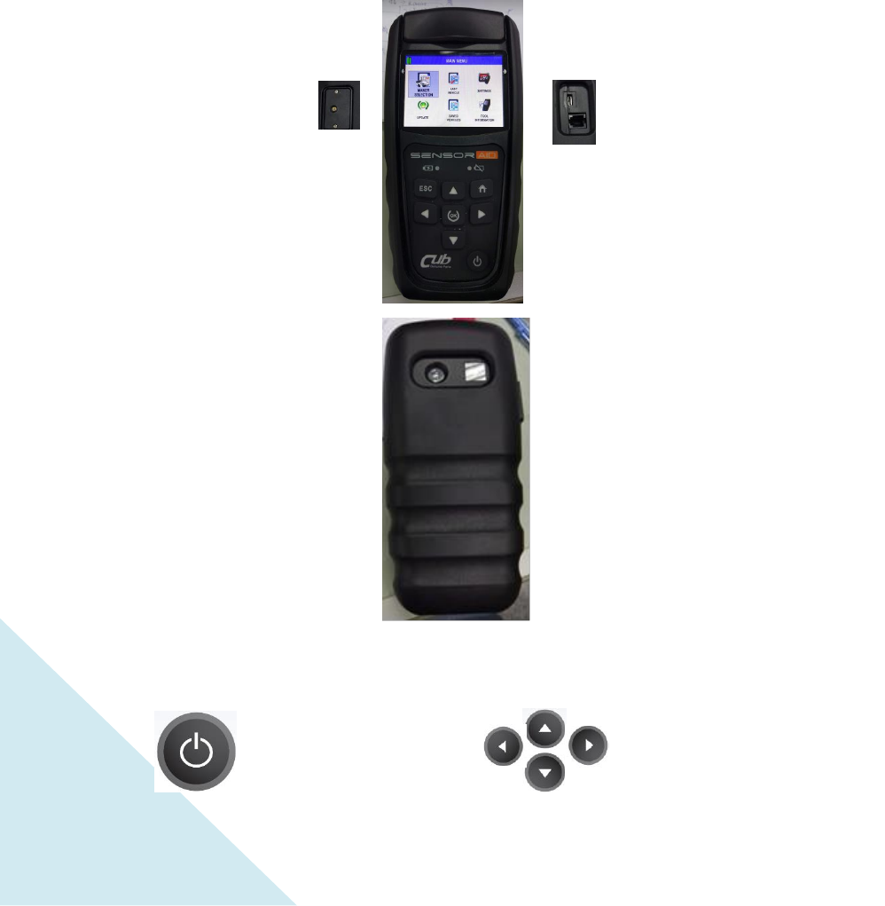
1. Sensor AID DUO TPMS TOOL
Introduction
Sensor AID DUO TPMS TOOL, henceforth called Sensor AID DUO, is
designed
to
promote CUB Uni-Sensor in the whole world. Sensor AID DUO TOOL can diagnose
and interact with tire pressure sensor through wireless (radio frequency)
communication to:
• Retrieve data from tire pressure sensor
• Verify the identity of each tire pressure sensor mounted on the wheels.
• Assist technicians in servicing CUB Uni-Sensor during relearn procedures.
NOTE: Sensor shall be diagnosed close to left or right antenna.
1.1
Appearance
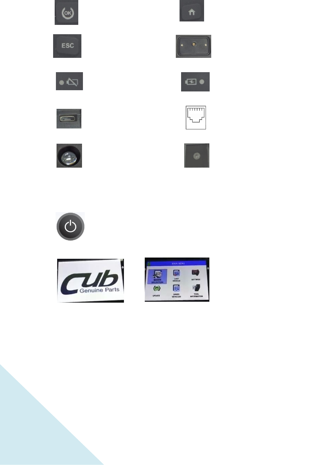
1.2 Keypad Summary
Power
On / Off
Navigate through measured
and parameters
by pressing
keys
4
2
. Function
OK key, press it to
validate or process
function.
The Micro-USB connection
For charging (5V/2A) /
IDtoPC / updating
Indicator will turn red
when battery is low
Indicator will turn orange
when charging
Esc key, press it to return
to the previous menu
without parameter
validation
Press and hold the power key for 3 seconds to power on the device
During power on, The
device display the CUB
logo
Now the device is at the
MAIN MENU
RJ11 cable.
Function pending
Home key, Back to main
menu
Tread Depth mechanism.
This function is for the
60U029 series.
LED for Camera
AF Camera
5
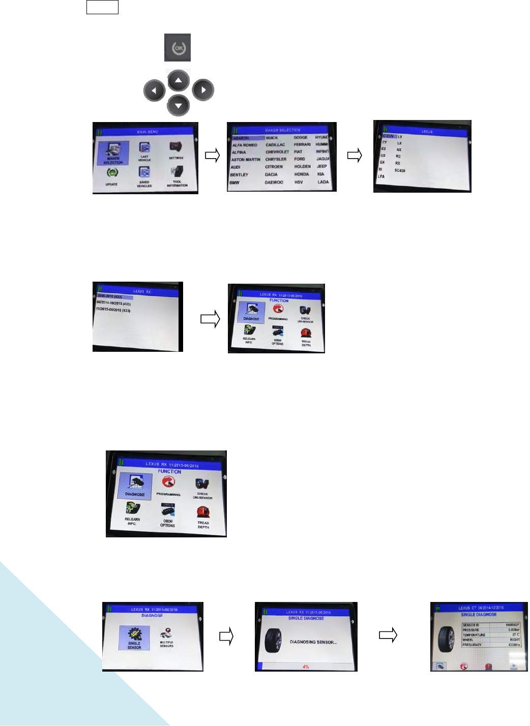
MAKER selection:
Use the arrow key
to browse automakers,
press the “OK” key to
select
MODEL selection:
Use the arrow key
to browse model, press
the “OK” key to select.
YEAR selection:
Use the arrow key
to browse model, press
the “OK” key to select.
MAIN MENU:
Use the arrow key
to browse function, press
the “OK” key to select
FUNCTION selection.
Press the “OK” key to
select DIAGNOSE
function.
Press “OK” key to enter.
2.1 MAKER SELECTION
NOTE: Definition
OK key : Select / Validate / Process
2.1.1 DIAGNOSE
2.1.1.1
Diagnose SINGLE SENSOR
Arrow Key : Use arrow keys to browse
maker.
6
Use the arrow key to select
diagnose “SINGLE
SENSOR” or “MULTIPLE
SENSORS” and press the
“OK” key to select.
Press “OK” key to
diagnose.
Use the arrow key
to browse MULTIPLE
SENSORS, press the
“OK” key to select.
After retrieving data from
sensor, the indicator light
will automatically move to
next wheel. Press “OK”
key to diagnose. Use the
same procedure for the
other wheels.
NOTE The Sensor AID will identify the sensor
information
that
is
transmitted.
Not
all
sensors transmit every
piece of information
shown.
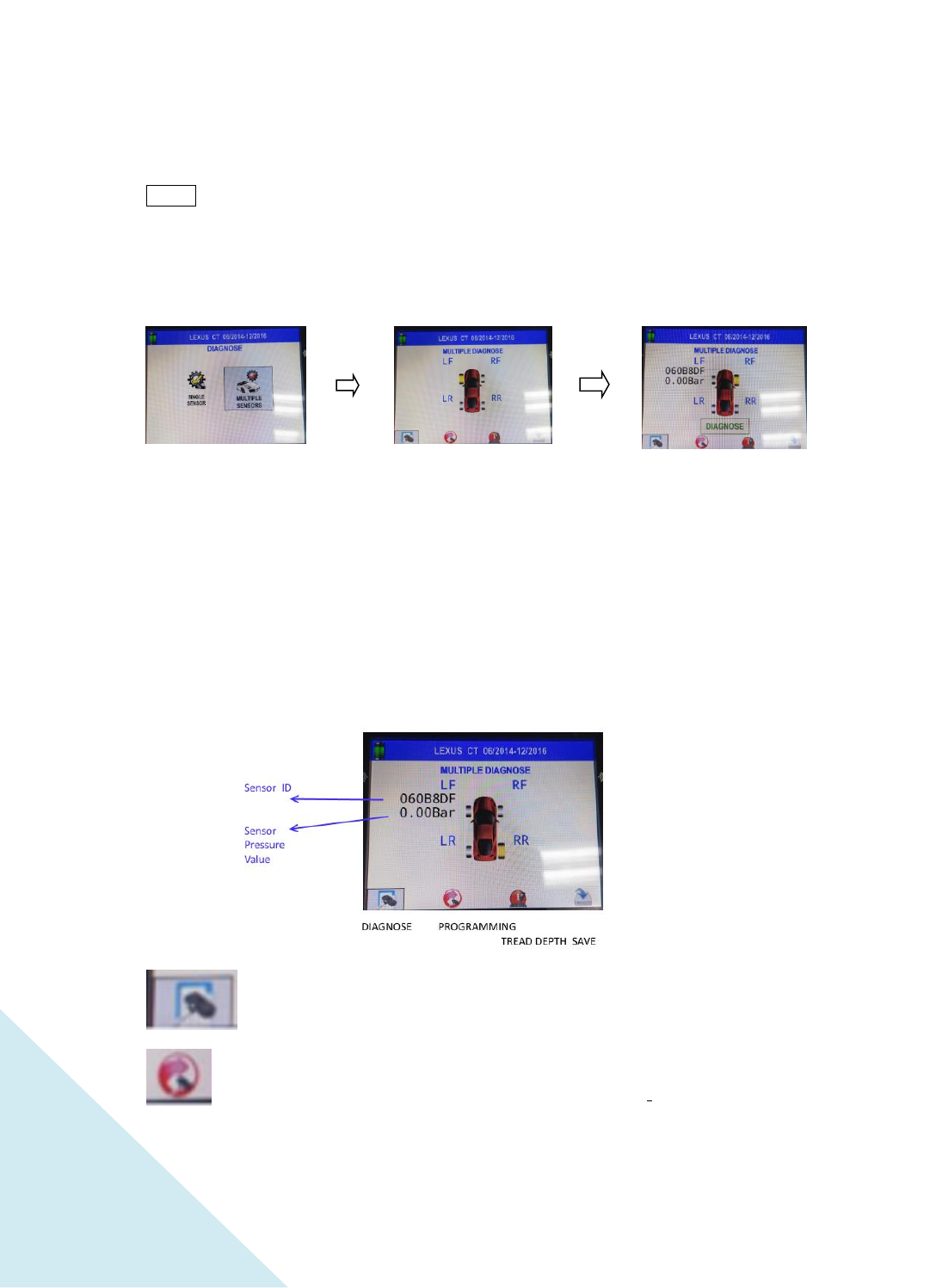
2.1.1.2
Diagnose MULTIPLE SENSORS
The
picture
below is an
example
of sensor data
communication result
DIAGNOSE: To diagnose sensor information.
PROGRAMMING : a shortcut to the Programming menu. (See page 6).
Sensor AID will now activate
the sensor. Sensor response
time may vary depending on
sensor type and brand. Sensor
AID will sound after receiving
sensor information.
The picture above is an
example of sensor data
communication result
7
Press “OK” key to
program.
Use the arrow key
to browse WIRELESS (as
example). Press “OK” key
to program.
Select New Sensor.
Press “OK” key to enter.
See step 2.1.1, then use
arrow key to browse.
Press “OK” key to enter.
TREAD DEPTH: To process TREAD DEPTH function (See page xxx).
SAVE: To save the existing data to SAVED VEHICLES menu (will be enabled when
there is existing data, see page XX).
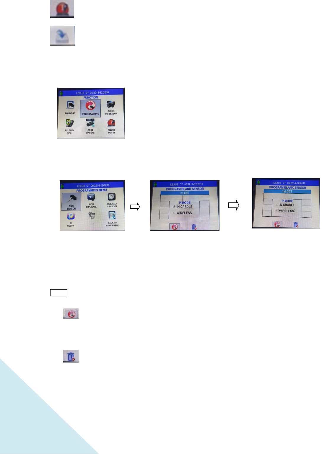
2.1.2 PROGRAMMING
2.1.2.1
NEW SENSOR
HINT:
IN CRADLE: Indicates programming by wire (Uni-Sensor must be placed inside cradle).
WIRELESS: Indicates programming by wireless (Wireless Uni-Sensor must be within
programming range from the tool)
NOTE: Make sure there are no other Wireless Uni-Sensors within 1 m from the tool when you
use wireless programming ; otherwise, the programming will fail.
Program blank sensor. When selected and pressing the “OK” key, it will
automatically program the next Uni-Sensor in the same way (in cradle/wireless) as previously
selected.
DEL ALL: Delete all the existing data of all the previously programmed
Uni-Sensors.
8
See step 2.1.2, then use
arrow key to browse.
Press “OK” key to enter.
See step 2.1.2, then use
arrow key to browse.
Press “OK” key to enter.
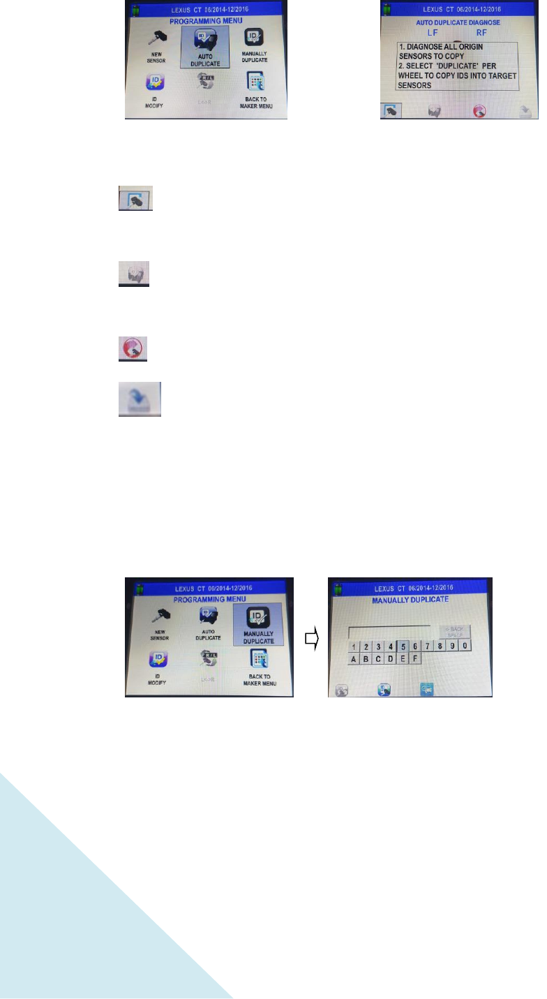
Use the arrow keys
to browse. Press “OK”
key at each character to
enter the ID, then select
Duplicate and press “OK”
key.
Please check if O.E
sensor ID is Hexadecimal
(0~9+A~F) or Decimal
(0~9) to select correct
mode in Manual
Duplicate.
An instruction message
will be displayed during 4
seconds, then will
automatically disappear
2.1.2.2
AUTO DUPLICATE
DIAGNOSE: If there is no existing data, diagnose all sensors that you wish to duplicate at
the beginning
DUPLICATE: Will be enabled when at least one sensor is diagnosed. Select it and press
“OK” to duplicated all previously diagnosed sensor.
PROGRAMMING: a shortcut to the Programming menu.
SAVE: To save the existing data to SAVED VEHICLES menu (will be enabled when there
is existing data, see page XX).
2.1.2.3
MANUALLY DUPLICATE
9
See step 2.1.2, then use
arrow key to browse.
Press “OK” key to enter.
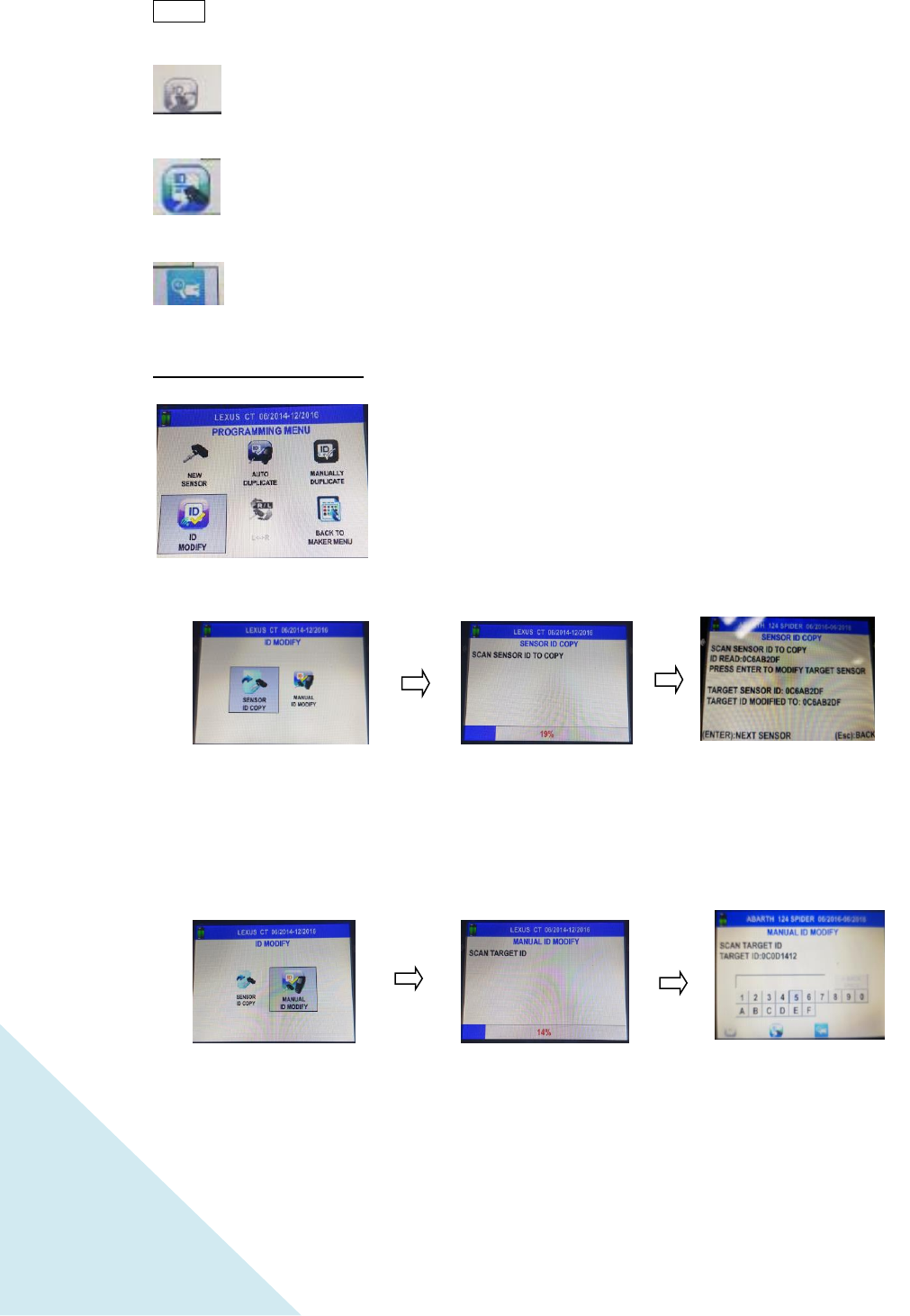
Press “OK” key to enter.
Press “OK” key to enter.
Function immediately
starts scanning for a
source sensor whose ID
will be copied.
After source ID is
detected, press “OK” key
to copy ID into target
sensor.
Function immediately
starts scanning for a
source sensor whose ID
will be copied.
After source ID is
detected, key in new ID
by means of the
keyboard, then select
Modify and press “OK”
key.
NOTE Duplicate and Programming functions will only work with CUB’s Sensor-AID and
Uni-sensor.
Duplicate: To duplicate a manual ID to a Uni-Sensor (will be enabled after keying in
first character).
HEX to DEC: To change between HEX and DEC ID formats (enabled at the beginning,
becomes disabled once first character is keyed in).
ID VIEW: To see the ID location on the OE sensor.
2.1.2.4
ID MODIFY
2.1.2.4.1 SENSOR
ID COPY
2.1.2.4.2 MANUAL
ID MODIFY
10
See step 2.1.2, then use
arrow key to browse.
Press “OK” key to enter.
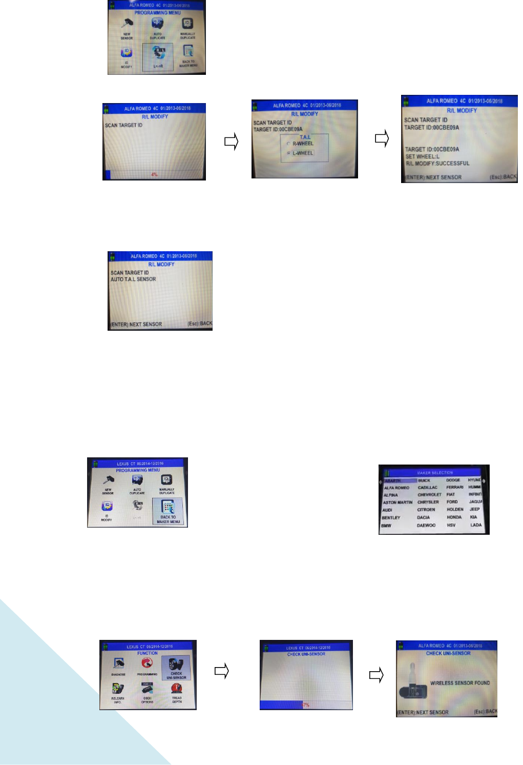
Function immediately
starts scanning for a
source sensor whose
side will be changed.
If a Wireless Sensor is
detected, the message
above is displayed. Press
“ESC” key to go back.
Once source ID is
detected, select side to
program to
The above message
confirms the successful
side programming.
See step 2.1.2, then use
arrow key to browse.
Press “OK” key to enter.
2.1.2.5
L <-> R
2.1.2.6 BACK TO MAKER MENU
2.1.3 CHECK UNI-SENSOR
Back to MAKER SELECTION
11
See step 2.1.1 then use
arrow key to browse.
Press “OK” key to enter.
.
See step 2.1.1 then use
arrow key to browse.
Press “OK” key to enter.
See step 2.1.1 then use
arrow key to browse.
Press “OK” key to enter.
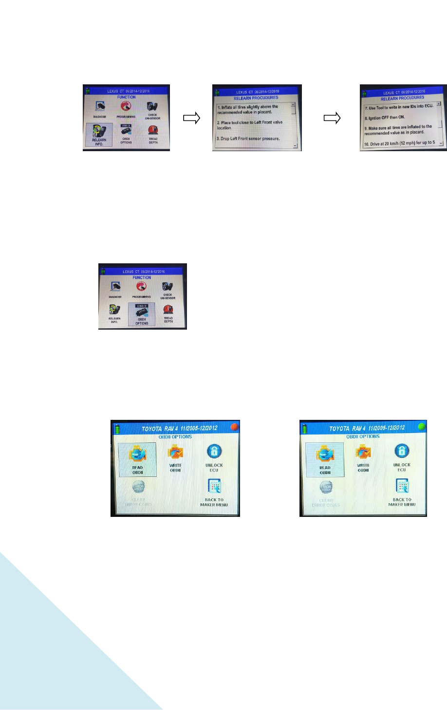
2.1.4 RELEARN INFO.
2.1.5 OBD II OPTIONS
(BT disconnect) (BT connecting)
Note: When you exit OBDII OPTION and back to OBDII OPTION
immediately, it will cost 5-10 second to re-connect.
Function immediately
starts scanning for a
Uni-Sensor.
Once detected, the
screen above is
displayed. Press “OK”
key to scan the next
sensor, or “ESC” to go
back
Use up and down arrow
keys to scroll.
12
Press “OK” key to enter.
Press “OK” key to enter.
Press “OK” key to enter.
Press “OK” key to enter.
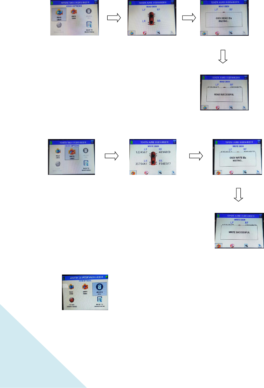
2.1.5.1 READ ID
2.1.5.2 WRITE ID
2.1.5.3 UNLOCK ECU
for some certain vehicles( Toyota )
13
See step 2.1.1 then use
arrow key to browse.
Press “OK” key to enter.
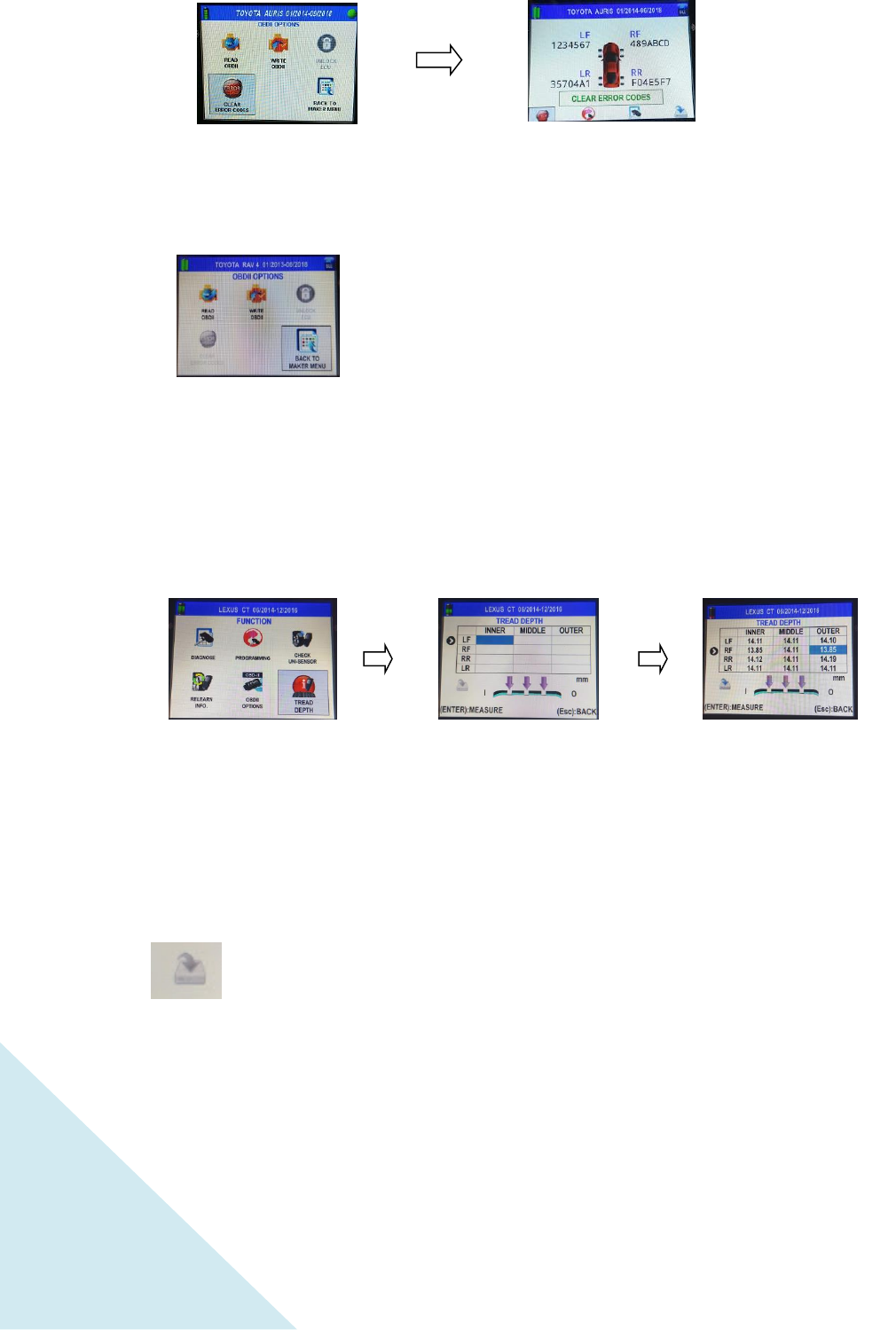
Place tool with tread
depth device in line with
tread, then press “OK”
key at each location
(inner, middle & outer) for
each tire.
You may retake a
measurement at any
position by simply
selecting it in the matrix,
then pressing “OK” key.
2.1.5.4 CLEAR DTC
2.1.5.5 BACK
Back to MAKER SELECTION
2.1.6 TREAD DEPTH
Alarm: Do not use the Tread Depth function on anyone’s
eyes, which can cause visual impairment.
SAVE (Will enable when there is existing data.)
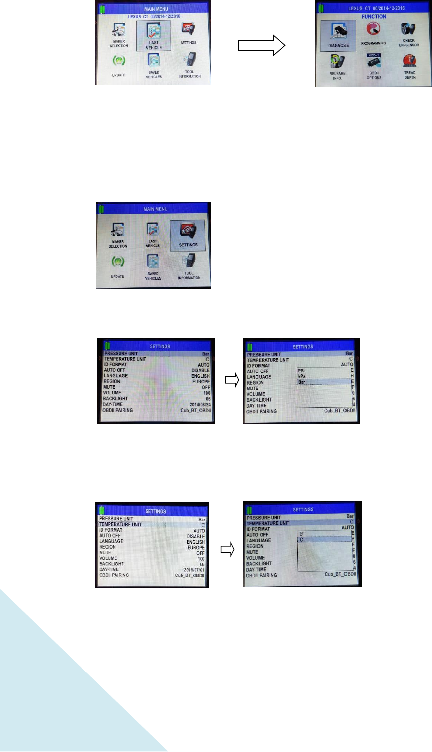
2.2 LAST VEHICLE
This function is the shortcut to the last picked MMY. Select it and the MMY will be displayed
above the icon. Press “OK” key to enter its function menu.
14
Press the “OK” key to
select.
Use the arrow keys
to browse units, press the
“OK” key to select.
See step 2.1,then use
arrow key to browse.
Press “OK” key to enter.
Press the “OK” key to
select.
Use the arrow keys
to browse units, press the
“OK” key to select.
( LEXUS CT 06/2014-12/2016)
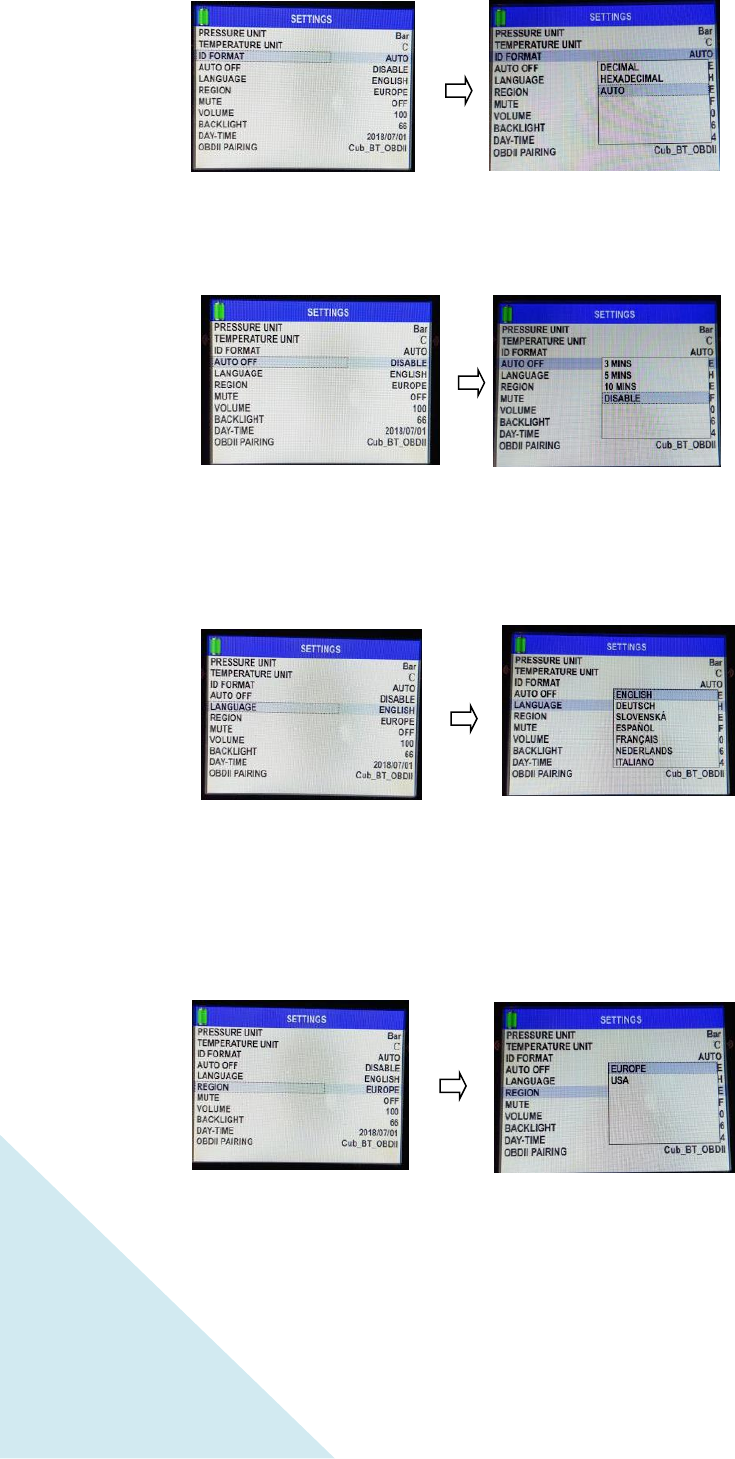
2.3 SETTINGS
2.3.1 PRESSURE UNIT
2.3.2 TEMPERATURE UNIT
15
Press the “OK” key to
select.
Use the arrow keys
to browse formats, press
the “OK” key to select.
Press the “OK” key to
select.
Use the arrow keys
to browse options, press
the “OK” key to select.
Press the “OK” key to
select.
Use the arrow keys
to browse languages,
press the “OK” key to
select.
Press the “OK” key to
select.
Use the arrow keys
to browse regions, press
the “OK” key to select.
2.3.3 ID FORMAT
2.3.4 AUTO OFF
2.3.5 LANGUAGE
2.3.6 REGION
16
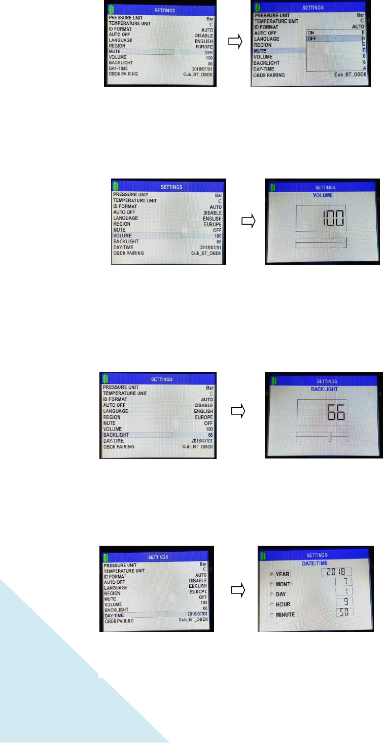
Use the arrow keys
to browse options, press
the “OK” key to select.
Press the “OK” key to
select.
Press the “OK” key to
select.
Press the “OK” key to
select.
Use the arrow keys
to browse volume levels,
press the “OK” key to
select.
Press the “OK” key to
select.
Use the arrow keys
to browse backlight
levels, press the “OK” key
to select.
Press the “OK” key to
select.
Use the arrow keys
to adjust date and time,
then press “OK” to set.
2.3.7 MUTE
2.3.8 VOLUME
2.3.9 BACKLIGHT
2.3.10 DAY-TIME
17
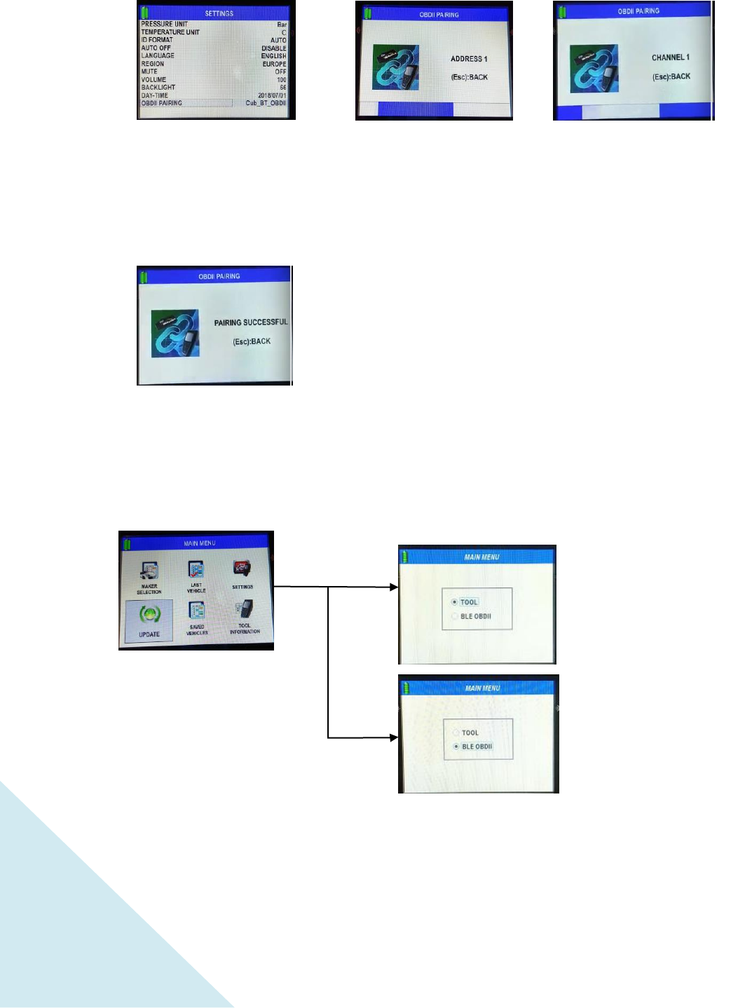
Connect the Cub BLE OBD
II Module to the OBD port of
the vehicle, then turn ACC
on. In the Sensor AID,
under Settings, select OBD
II pairing and then press
“OK” key to select
The pairing process begins
immediately; it may take
several seconds.
Wait for the process to
complete.
Once the paring is
completed, the above
message is displayed.
2.3.11 BT OBD II PAIRING
2.4 UPDATE
Update tool by PC
software.
Update BT OBD II
Moudle.
(Make sure BT
Moudle is plug on a
vehicle.)
18
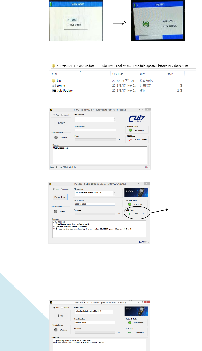
2.4.1 WIRE UPDATE by PC software
1.
2.Extract the file [Cub] TPMS Tool & OBD-II Module Update Platform v1.7 (beta2)(lite).zip
3.Execute Cub Updater.exe
4. Connect Mico usb to TOOL and PC usb port.
5. Click “Download” for auto update
5.1 SN is invalid. You will see the error message “ Serial number “0000F0F10F00” cannot be
found”. Please contact your distributor/dealer.
Enter
Appear
connect
19
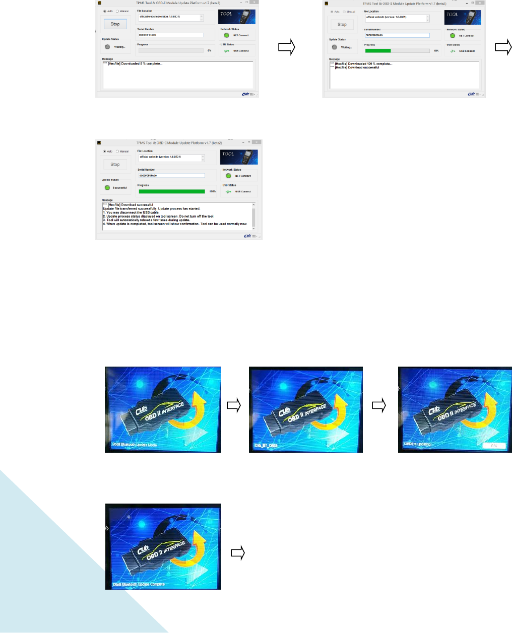
5.2 SN is valid.
2.4.2 BT OBD II module UPDATE
Note: Before you do the OBDII update, please plug OBD II module into an OBD II connector of
any vehicle in order to have the power source for the OBDII module.
Update Mode
Cub_BT_OBDII
OBDII is updating
Reboot
Download file from server
Transmit file to tool
Transmit completed.
Disconnect usb cable. Wait for
tool update.
20
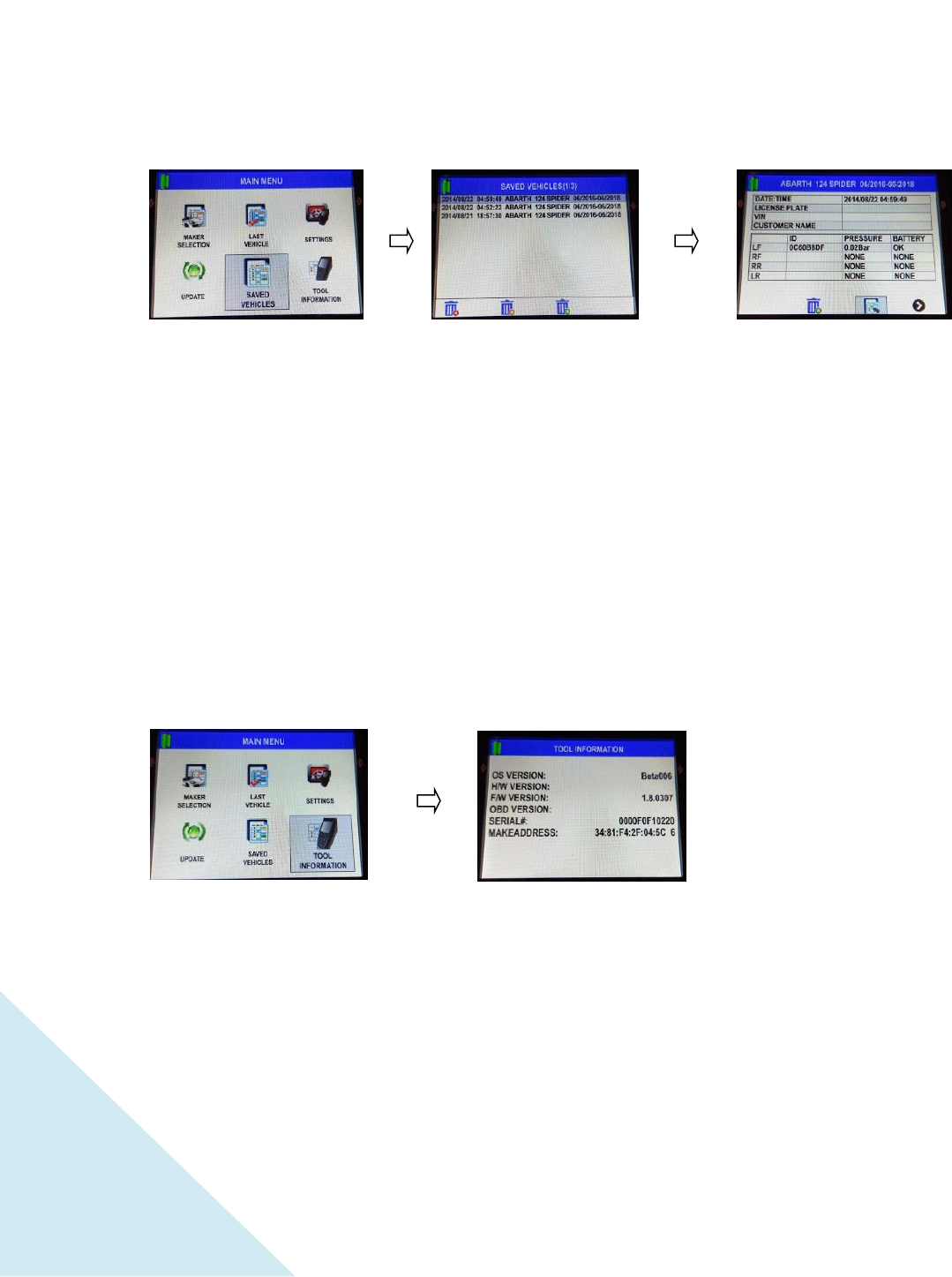
See step 2.1, then use
arrow key to browse.
Press “OK” key to enter.
Use arrow keys to select
saved vehicle, press “OK”
key to enter.
There are three options
underneath:
DEL ALL – Deletes all
data
DEL OLDEST – Deletes
oldest saved vehicle only
DEL SELECTED –
Deletes selected saved
vehicle only
See step 2.1,then use
arrow key to browse.
Press “OK” key to enter.
Tool information is displayed:
OS – Operating Sytem
H/W – Hardware
F/W – Firmware
MAC ADDRESS
2.5 SAVED VEHICLES
DEL ALL DEL OLDEST DEL SELECTED
2.6 TOOL INFORMATION
Update Complete

21
3
. Warranty
CUB autoparts
products
are guaranteed from material defects for 365
days
after the
date of purchase. lf the
product
fails under normal
circumstances
within the first year,
CUB autoparts will repair or replace the
product
.
Product will
not be replaced or
repaired if damaged from misuse or
incorrect application.
To
obtain repair or
replacement of the
product
under
warranty,
contact local
distributor.
Proof of
purchase and date of purchase is required
to
validate the warranty
claim.
CUB
autoparts
is not liable for any direct or consequential loss or
property
damage
arising from use of
product.
NOTE Warranty does not cover tire valves or screws for tire valves
.
The
tire
valves and screws need to be replaced when rotating
tires,
changing
tires or changing the TPMS
sensors.
If
installing /
reinstalling
a TPMS
sensor, new valves and
screws
should be
used.
Warning: Only use Cub autoparts
replacement
parts. Using other
brands
will
not allow the system to work and will void the
warranty.
Caution
Read
these simple
guidelines. Not following them may be dangerous
or
illegal. Read the
complete user guide for further
information.
SWITCH
ON SAFELY
Do not switch the device on when wireless use
is
prohibited
or when it
may
cause interference
or
danger.
SWITCH OFF
NEAR BLASTING
Fellow any
restrictions, Do
not use the device
where
blasting
is in
progress.
USE SENSIBLY
Use only in the
normal
position as explained in the product documentation. Do
not touch the
antenna
unnecessarily.
WATER·RESISTANCE
The device is
not
water-resistant. Keep it
dry.
ENHANCEMENTS AND SATTERIES
Use only
approved
enhancements
and batteries. Do not
connect
incompatible products. The
battery
needs to be charged to
full
for the first
usage.
SWITCH OFF
WHEN REFUELLING
Do not use the device at a
r
efueling point. Do
not
use near fuel
or
chemicals.

22
I
NTERFERENCE
All wireless devices
may
be susceptible
to
interference, which
could
affect
performance.
CONNECTING
TO
OTHER
DEVICES
When
connecting
to any other device, read its
user
guide for detailed
safety
instructions.
Do not connect
incompatible products.
QUALIFIED
SERVICE
Only
qualified personnel
may install or repair
this
device.
RISK OF EXPLOSION IF BATTERY IS REPLACED BY AN
INCORRECT TYPE. DISPOSE OF USED BATTERIES ACCORDING TO
THE INSTRUCTIONS.
FCC
Statement
This
equipment
has been tested and found to comply with the Iimits for a Class B digital
device, pursuant to Part 15 of the
FCC R
ules.
These Iimits are
designed
to provide
reasonable
protection
against
harmful
interference in a
residential
installation. This
equipment
generates, uses and can radiate radio
frequency
energy and, if not installed
and used in accordance with the
instructions, may
cause harmful interference to radio
communications.
However,
there is
no
guarantee that interference will not occur in a
particular installation.
lf
this
equipment
does cause
harmful
interference to radio or
television
reception,
which can be
determined
by
turning
the
equipment
off and on,
the user is
encouraged to try to correct the interference by one of the following
measures:
• Reorient or relocate the receiving
antenna.
• lncrease the separation between the
equipment
and receiver.
• Connect the
equipment
into an outlet on a circuit different from that to
which
the receiver is
connected.
• Consult the dealer or an experienced
radio/TV
technician for help.
IC
Statement
The
requirement
is specified in
RSS-GEN
Section 5.3. This device complies with
Industry
Canada license-exempt RSS standard(s). Operation is subject to
the
following
two
conditions:
(1) this device may not cause interference, and (2)
this
device must
accept any interference, including
interference that may
cause
undesired operation of
the device.
CE
Compliance
Notice
All
CE
marked HERTH+BUSS sensor products are in
compliance
with the essential requirements and other relevant
provisions of Directive 1999/5/EC. A copy of the Declaration of
Conformance will be provided upon request.

23
15.21
You are cautioned that changes or modifications not expressly approved by the part
responsible for compliance could void the user’s authority to operate the equipment.
15.105(b)
This equipment has been tested and found to comply with the limits for a Class B digital
device, pursuant to part 15 of the FCC rules. These limits are designed to provide reasonable
protection against harmful interference in a residential installation. This equipment
generates, uses and can radiate radio frequency energy and, if not installed and used in
accordance with the instructions, may cause harmful interference to radio communications.
However, there is no guarantee that interference will not occur in a particular installation. If
this equipment does cause harmful interference to radio or television reception, which can
be determined by turning the equipment off and on, the user is encouraged to try to correct
the interference by one or more of the following measures:
-Reorient or relocate the receiving antenna.
-Increase the separation between the equipment and receiver.
-Connect the equipment into an outlet on a circuit different from that to which the
receiver is connected.
-Consult the dealer or an experienced radio/TV technician for help.
This device complies with Part 15 of the FCC Rules. Operation is subject to the following two
conditions:
1) this device may not cause harmful interference, and
2) this device must accept any interference received, including interference that may cause
undesired operation of the device.
SAR FCC RF Radiation Exposure Statement:
Federal Communication Commission (FCC) Radiation Exposure Statement
This EUT is compliance with SAR for general population/uncontrolled exposure limits in
ANSI/IEEE C95.1-1999 and had been tested in accordance with the measurement methods
and procedures specified in OET Bulletin 65 Supplement C.

24
Canada, Industry Canada (IC)
This Class B digital apparatus complies with Canadian ICES-003
Cet appareil numérique de classe B est conforme à la norme NMB-003.
This device complies with Industry Canada licence-exempt RSS standard(s). Operation
is subject
to the following two conditions: (1) this device may not cause interference, and (2) this device
must accept any interference, including interference that may cause undesired operation of the
Le présent appareil est conforme aux CNR d'Industrie Canada applicables auxappareils radio
exempts de licence.L'exploitation est autorisée aux deux conditions suivantes:
(1) l'appareil ne doit pas produire de brouillage, et
(2) l'utilisateur de l'appareil doit accepter tout brouillage adioélectrique subi, même si le
brouillage est susceptible d'en compromettre le fonctionnement.
SAR IC RF Radiation Exposure Statement:
The product comply with the Canada portable RF exposure limit set forth for an uncontrolled
environment and are safe for intended operation as described in this manual.
Déclaration d'exposition aux radiations:Le produit est conforme aux limites d'exposition
pour les appareils portables RF pour les Etats-Unis et le Canada établies pour un
environnement non contrôlé.
CUB
ELECPARTS
INC
No.6, Lane 546, Sec. 6, Chang Lu
Rd.,
Fuhsin
Hsiang,Chang
Hua County, Taiwan
http:/
/www.cubautoparts.com
To obtain repair or replacement of the product under warranty, or general
inquiries, assistance, please refer to CUB
information
card to contact our
local
distri
butor.