Cadi Scientific SMB800 SmartBRIDGE User Manual SMB 800 instructions for use
Cadi Scientific Pte. Ltd. SmartBRIDGE SMB 800 instructions for use
Contents
- 1. manual
- 2. manual2
- 3. manual1
manual1

C
Ca
ad
di
i
S
Sc
ci
ie
en
nt
ti
if
fi
ic
c
P
Pt
te
e
L
Lt
td
d
S
SM
MB
B-
-8
80
00
0
S
Sm
ma
ar
rt
tB
Br
ri
id
dg
ge
e
I
In
ns
st
tr
ru
uc
ct
ti
io
on
ns
s
F
Fo
or
r
U
Us
se
e
Document No.:
Established Date: 28 October 2009
Revision: B

C
Ca
ad
di
i
S
Sc
ci
ie
en
nt
ti
if
fi
ic
c
P
Pt
te
e
L
Lt
td
d
Document: Document No.:
Dept. of
preparation: Revision: Issue
Date:
Date Revision Contents of Revision Revised by Reviewed by Approved by
28 October
2009 A New Ng Ken
Wee
22
September
2010 B Update
Ng Ken
Wee

C
Ca
ad
di
i
S
Sc
ci
ie
en
nt
ti
if
fi
ic
c
P
Pt
te
e
L
Lt
td
d
Document: Document No.:
Dept. of
preparation: Revision: Issue
Date:
Notices
Copyright © 2010 Cadi Scientific Pte Ltd.
No part of this manual may be reproduced in any form or by any means (including electronic
storage and retrieval or translation into a foreign language) without prior agreement and
written consent from Cadi Scientific Pte Ltd as governed by international copyright laws.
Regulatory Information
For customer in the U.S.A and Canada
The SMB-800 SmartBRIDGE (FCC ID: VPE-SMB800) has been tested and found to comply
with the limits for a Class B digital device, pursuant to part 15 of the FCC rules. These
limits are designed to provide reasonable protection against harmful interference in a
residential installation. This equipment generates, uses and can radiate radio frequency
energy and, if not installed and used in accordance with the instructions, may cause
harmful interference to radio communications. However, there is no guarantee that
interference will not occur in a particular installation. If this equipment does cause
harmful interference to radio or television reception, which can be determined by turning
the equipment off and on, the user is encouraged to try to correct the interference by one
or more of the following measures:
- Reorient or relocate the receiving antenna.
- Increase the separation between the equipment and receiver.
- Connect the equipment into an outlet on a circuit different from that to which the
receiver is connected.
- Consult the dealer or an experienced radio/TV technician for help.
Operation is subject to the following two conditions:
(1) This device may not cause harmful interference, and
(2) This device must accept any interference received, including interference that may
cause undesired operation.
This equipment complies with FCC radiation exposure limits set forth for an uncontrolled
environment. End users must follow the specific operating instructions for satisfying RF exposure
compliance. This transmitter must not be co-located or operating in conjunction with any other
antenna or transmitter.
The lithium battery inside this product contains Perchlorate. The following statement is required
by the State of California, USA:
Perchlorate Material – special handling may apply.
Changes or modifications not expressly approved by the manufacturer could void the user’s
authority to operate the equipment.
For customer in Europe
This equipment has been tested and found to comply with the limits set out in the R&TTE
Directive.
C
Ca
ad
di
i
S
Sc
ci
ie
en
nt
ti
if
fi
ic
c
P
Pt
te
e
L
Lt
td
d
Document: Quality Objectives and Quality Planning Control
Procedures Document No.: MDDQP-001-A2
Dept. of
preparation: Management
Representative Revision: B01 Issue
Date: 28 Oct 2009 Page 4 of 29
Annex II
Where you see this symbol on any of our electrical products/packaging in Europe, it means that
at end of life the product/battery must be disposed of in accordance with any applicable laws or
requirements for the separate disposal of electrical equipment/batteries.

C
Ca
ad
di
i
S
Sc
ci
ie
en
nt
ti
if
fi
ic
c
P
Pt
te
e
L
Lt
td
d
Document: Quality Objectives and Quality Planning Control
Procedures Document No.: MDDQP-001-A2
Dept. of
preparation: Management
Representative Revision: B01 Issue
Date: 28 Oct 2009 Page 5 of 29
Annex II
Product Information
Product model: CADI SMB-800
Product name: SmartBridge
Manufacturing site: 31 Ubi Road 1, #03-00 Aztech Building, Singapore 408694
Version Information
This version is subject to change or upgrade without notice
Version: A01
Issue date: xxxxxxxx
Declaration
Cadi Scientific Pte Ltd reserves the right to change the product described in this
Operating Manual. All information contained in this Operating Manual is subject to
change without prior notice.
Manufacturer’s Responsibility
Cadi Scientific is responsible for the safety, reliability and performance of the device
under the following conditions:
Assembling, upgrading, resetting and repairing are performed by Cadi’s authorized
personnel.
Operating this device following this manual.
Product serial number and labels are intact to verify the product identity as manufactured
by Cadi Scientific Pte Ltd.
Product storing environment, operating environment and electrical environment are as
described in this manual.
Damages not by misuse of accidental dropping.
Free services apply to products with applicable items within warranty period. For
products beyond the description of warranty conditions, service charge applies.
Customers are required to pay for any transportation and applicable customs fees of
returned goods to Cadi Scientific.
Return Proceedures
If return is necessary, take the following steps:
1. Obtain return goods authorization from Cadi Scientific Customer Service
Department. Inform Cadi Scientific of the serial number and mark this serial
number on the cartons. If the serial number cannot be recognized, the return
cannot be accepted. Describe briefly the reasons for return.
2. Frieght Charge: customer is responsible for freight charges (including customs) for
any returns.
C
Ca
ad
di
i
S
Sc
ci
ie
en
nt
ti
if
fi
ic
c
P
Pt
te
e
L
Lt
td
d
Document: Quality Objectives and Quality Planning Control
Procedures Document No.: MDDQP-001-A2
Dept. of
preparation: Management
Representative Revision: B01 Issue
Date: 28 Oct 2009 Page 6 of 29
Annex II
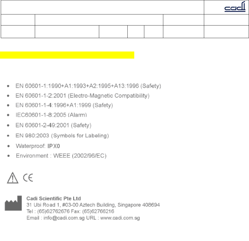
Standards Compliance
This SmartBridge meets the following standards
C
Ca
ad
di
i
S
Sc
ci
ie
en
nt
ti
if
fi
ic
c
P
Pt
te
e
L
Lt
td
d
Document: Quality Objectives and Quality Planning Control
Procedures Document No.: MDDQP-001-A2
Dept. of
preparation: Management
Representative Revision: B01 Issue
Date: 28 Oct 2009 Page 7 of 29
Annex II
1. Safety
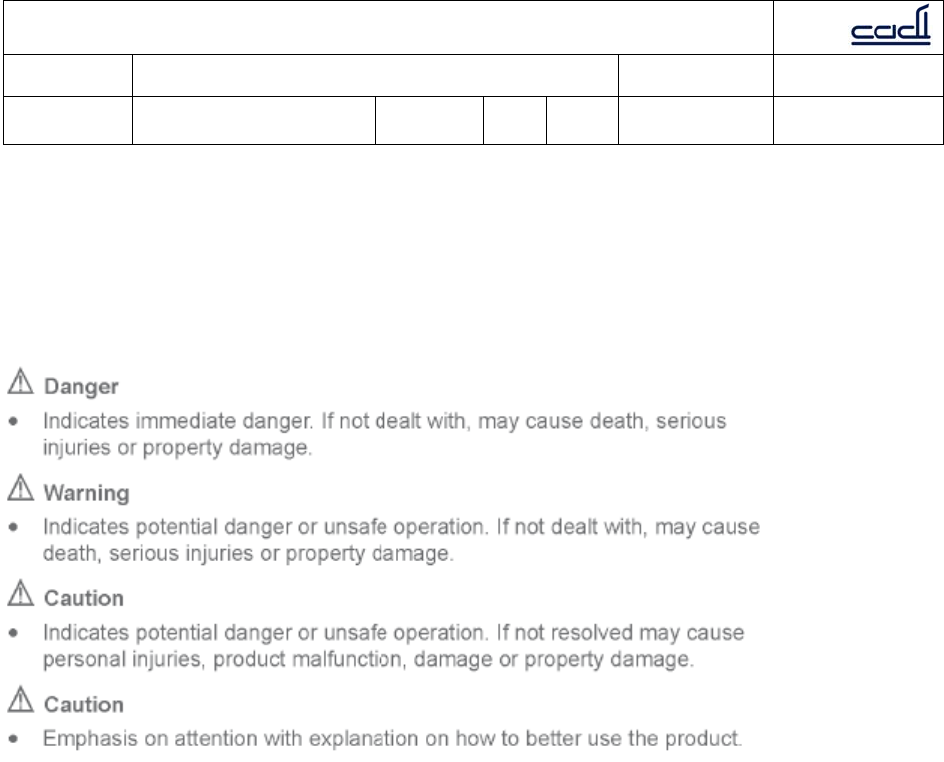
1.1 Safety Information
This chapter lists all warnings, attentions and basic safety information when using
CADI SMB-800 SmartBridge. Other safety information can be found in appropriate
chapters.
1.1.1 Danger
There is no safety information on levels of danger.
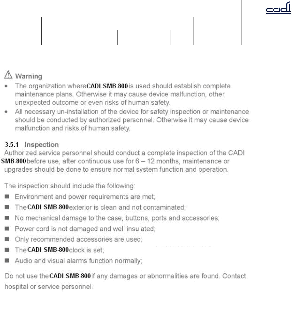
1.1.2 Warning
Only professional doctors and nurses can use this CADI SMB-800 for clinical monitoring
under certain conditions.
Before using CADI SMB-800, users must check the device and its accessories to ensure
its proper function and safety.
Disposable accessories should be disposed according to the regulations of the hospital.
Do not use CADI SMB-800 in an environment where flammable substances are present.
Users should set alarm settings according to patient types and conditions.
Do not open CADI SMB-800 case. Otherwise, it may cause serious injuries or death.
Do not use on patients during defibrillation. Otherwise, it may cause serious injuries or
death.
Ensure patient safety when using CADI SMB-800 with other electrical surgical devices.

C
Ca
ad
di
i
S
Sc
ci
ie
en
nt
ti
if
fi
ic
c
P
Pt
te
e
L
Lt
td
d
Document: Quality Objectives and Quality Planning Control
Procedures Document No.: MDDQP-001-A2
Dept. of
preparation: Management
Representative Revision: B01 Issue
Date: 28 Oct 2009 Page 8 of 29
Annex II
The packaging material should be disposed according to local regulations and should be
kept in a place where no children can reach.
Connect CADI SMB-800 only with the provided power adapter. Use with any other
adapters may cause serious injuries or death.
1.1.3 Caution
Use accessories recommended in this manual to ensure patient safety.
Magnetic fields may affect the performance of CADI SMB-800. Any equipment in use
near CADI SMB-800 must be in compliance with EMC standards. Cell phones, X-ray or
MRI devices are possible interference sources, as they emit high electro-magnetism
radiation.
Before connecting CADI SMB-800 to power, ensure the voltage and frequency are in
accordance with the requirements on the adapter label or in the manual.
Install and transport CADI SMB-800 properly to prevent any damages caused by
dropping, impact, shakes or other mechanical forces.
This equipment should be installed and operated with minimum distance 20cm between
the radiator & your body.
1.1.4 Note
Note
Place this manual next to the CADI SMB-800 for convenience when needed.
The software for the CADI SMB-800 is developed in accordance with IEC60601-1-4
standards to minimize any risks caused by program errors.
Up to 1000 trend data storage.
Place CADI SMB-800 where easy observation, operation and maintenance can be
obtained.
C
Ca
ad
di
i
S
Sc
ci
ie
en
nt
ti
if
fi
ic
c
P
Pt
te
e
L
Lt
td
d
Document: Quality Objectives and Quality Planning Control
Procedures Document No.: MDDQP-001-A2
Dept. of
preparation: Management
Representative Revision: B01 Issue
Date: 28 Oct 2009 Page 9 of 29
Annex II
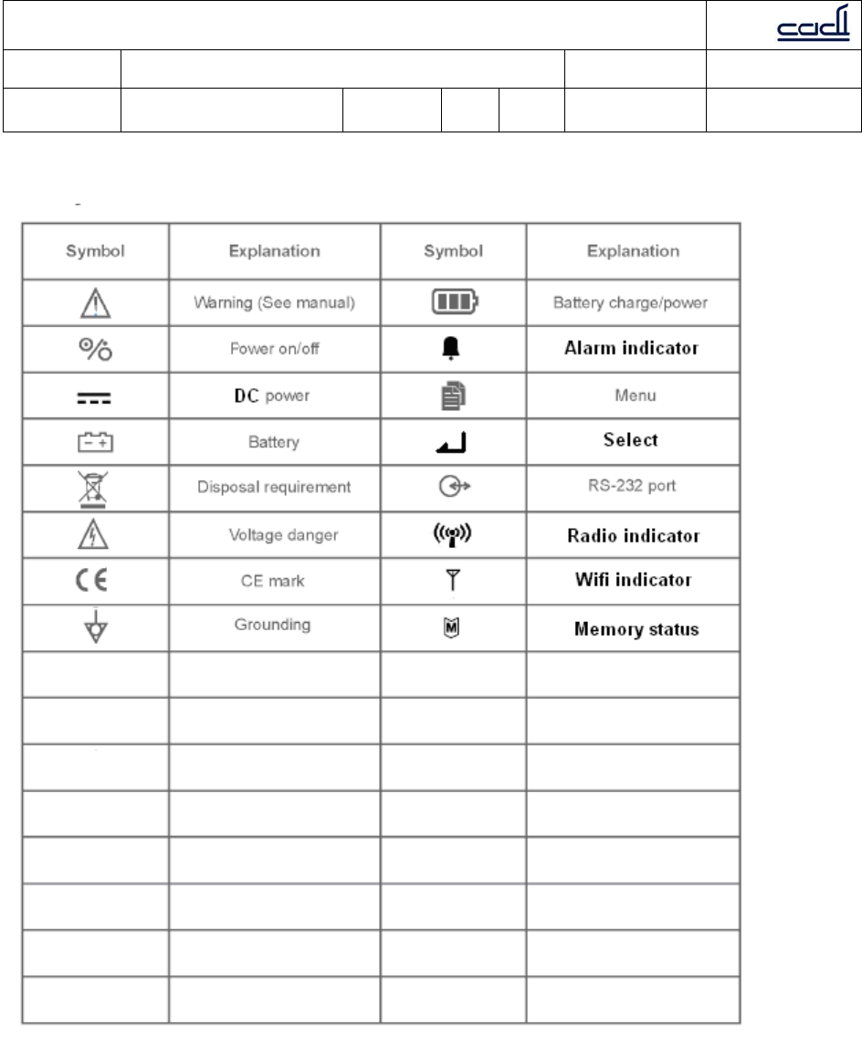
1.2 Symbols

C
Ca
ad
di
i
S
Sc
ci
ie
en
nt
ti
if
fi
ic
c
P
Pt
te
e
L
Lt
td
d
Document: Quality Objectives and Quality Planning Control
Procedures Document No.: MDDQP-001-A2
Dept. of
preparation: Management
Representative Revision: B01 Issue
Date: 28 Oct 2009 Page 10 of 29
Annex II
2. OVERVIEW
2.1 PRODUCT INTRODUCTION
2.1.1 Application range
CADI SMB-800 is intended for medical device connection. It is intended to connect to
devices such as non-invasive blood pressure monitors (NIBP), oxygen saturation of
arterial hemoglobin (SpO2) meters, pulse rate monitors, temperature monitors, and
other Vital Signs Monitors.
2.1.2 Product structure
CADI SMB-800 is composed of the main unit, and adapter power supply/charger.
CADI SMB-800 has the following functions and features:
1. Connecting up to four (4) medical devices to the RS232 communication ports.
2. Receiving ThermoSensor data thru the built-in radio.
3. Upload data thru Wifi 802.11b/g or radio to hospital infrastructure.
4. Display: LCD and LED
5. Battery: internal rechargeable lithium battery, coin cell backup battery.
C
Ca
ad
di
i
S
Sc
ci
ie
en
nt
ti
if
fi
ic
c
P
Pt
te
e
L
Lt
td
d
Document: Quality Objectives and Quality Planning Control
Procedures Document No.: MDDQP-001-A2
Dept. of
preparation: Management
Representative Revision: B01 Issue
Date: 28 Oct 2009 Page 11 of 29
Annex II
2.2 PRODUCT VIEW
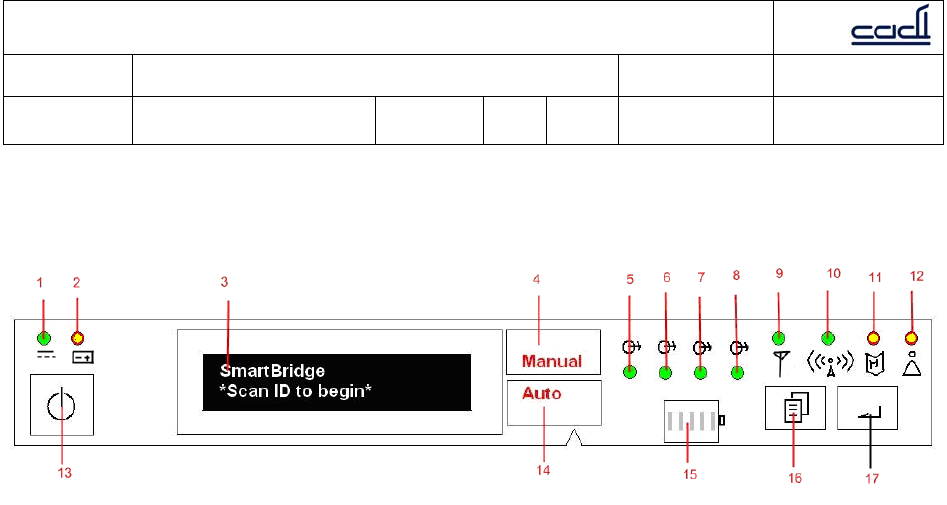
2.2.1 Front
1. DC power indicator: displays green when dc power adapter is connected.
2. Battery indicator: displays green when running on battery, blinks yellow when
battery is low.
3. LCD display: shows information on the 2 line display.
4. Manual mode indicator: displays “Manual” in red when device is in Manual mode.
5. Port 1 indicator: displays green when device connected and working properly.
Flashes yellow when there is error in this communication port.
6. Port 2 indicator: displays green when device connected and working properly.
Flashes yellow when there is error in this communication port.
7. Port 3 indicator: displays green when device connected and working properly.
Flashes yellow when there is error in this communication port.
8. Port 4 indicator: displays green when device connected and working properly.
Flashes yellow when there is error in this communication port.
9. Wifi indicator: displays green when active, flashes green when communicating,
flashes yellow when error.
10. Radio indicator: displays green when active, flashes green when communicating,
flashes yellow when error.
11. Memory indicator: flashes green when communicating, flashes yellow when
nearing full.
12. Alarm indicator: flashes yellow when alarm condition.
13. Power button: press and hold for at least 2 seconds to turn the CADI SMB-800 on
or off.
14. Auto mode indicator: displays “Auto” when device is in Auto mode.
15. Battery charge indicator: indicates battery is charging and quantity of battery
electric charge.
16. Menu button: used in combination with Select button to navigate menus and
settings.
17. Select button: used in combination with Menu button to navigate menus and
settings.
C
Ca
ad
di
i
S
Sc
ci
ie
en
nt
ti
if
fi
ic
c
P
Pt
te
e
L
Lt
td
d
Document: Quality Objectives and Quality Planning Control
Procedures Document No.: MDDQP-001-A2
Dept. of
preparation: Management
Representative Revision: B01 Issue
Date: 28 Oct 2009 Page 12 of 29
Annex II
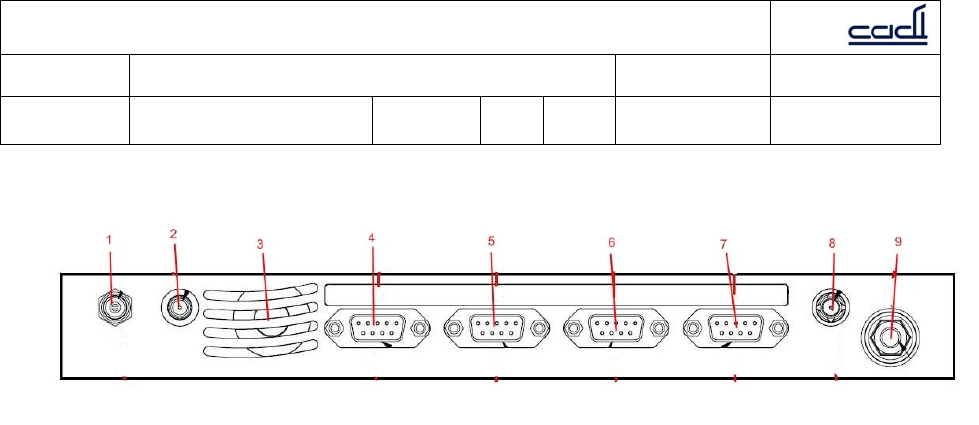
2.2.2 Rear
1. DC power socket.
2. Radio antenna connector.
3. Speaker vent.
4. RS232 port 1: used to connect to other device or PC
5. RS232 port 2: used to connect to other device or PC
6. RS232 port 3: used to connect to other device or PC
7. RS232 port 4: used to connect to other device or PC
8. Wifi antenna connector.
9. Common potential terminal (unused)
C
Ca
ad
di
i
S
Sc
ci
ie
en
nt
ti
if
fi
ic
c
P
Pt
te
e
L
Lt
td
d
Document: Quality Objectives and Quality Planning Control
Procedures Document No.: MDDQP-001-A2
Dept. of
preparation: Management
Representative Revision: B01 Issue
Date: 28 Oct 2009 Page 13 of 29
Annex II
3. INSTALLATION AND MAINTENANCE
3.1 INSTALLATION
CADI SMB-800 should be installed by authorized personnel. The software of CADI SMB-
800 belongs to Cadi Scientific Pte Ltd. No one should, in any manner, alter, copy or
exchange the software without prior permission from Cadi Scientific Pte Ltd.
C
Ca
ad
di
i
S
Sc
ci
ie
en
nt
ti
if
fi
ic
c
P
Pt
te
e
L
Lt
td
d
Document: Quality Objectives and Quality Planning Control
Procedures Document No.: MDDQP-001-A2
Dept. of
preparation: Management
Representative Revision: B01 Issue
Date: 28 Oct 2009 Page 14 of 29
Annex II
Note
Users should have designated personnel to install as needed.
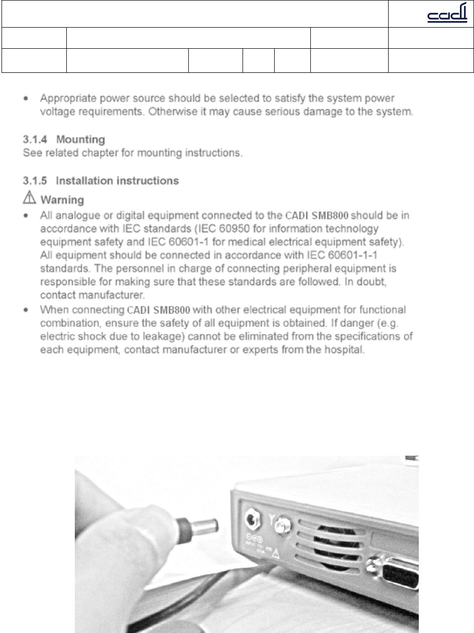
Connect adapter
1. Make sure the original adapter and power cord is used.
2. Plug the adapter into the back of the CADI SMB-800 as shown in figure 3-1.
3. Plug the power cord into a wall outlet.
Warning
Do not plug the into a socket controlled by a switch.
Do not use an adapter plug, use the correct power cord for your country.

C
Ca
ad
di
i
S
Sc
ci
ie
en
nt
ti
if
fi
ic
c
P
Pt
te
e
L
Lt
td
d
Document: Quality Objectives and Quality Planning Control
Procedures Document No.: MDDQP-001-A2
Dept. of
preparation: Management
Representative Revision: B01 Issue
Date: 28 Oct 2009 Page 15 of 29
Annex II
Connect devices
Connect vital sign monitor to port 1,2 or 3. Connect barcode scanner to port 4.
3.1.6 Power on
After installation, follow the following steps:
1. Before power on, see 3.1.1 to conduct safety inspection.
2. Press power on/off button. System conducts self test automatically (POST).
Note
During self test (POST), make sure all displays and indicators illuminate.
3. In the self test (POST), display testing takes about 2 seconds.
All indicators illuminate;
All LEDs illuminate;
The LCD light illuminates and the welcome screen is shown.
Note
If there are any indicators or displays that do not illuminate, do not use CADI SMB-
800. Contact sales or service representatives.
4. After self test for display functions, the welcome screen in the LCD will display the
software version.
The battery might be drained during transportation or storage. If the CADI SMB-800 has
been stored for more than 2 months, it is necessary to re-charge the battery before use
by plugging the CADI SMB-800 into an AC power outlet for at least 30 minutes.
Regardless whether the CADI SMB-800 is powered off or on, the battery will be fully
charged in about 6 hours if the AC power is connected to the CADI SMB-800.
Note
Whenever CADI SMB-800 is connected to AC power, the battery will be charged. Please
keep CADI SMB-800 connected with the AC power even when it is not in use to ensure a
fully charged battery. A connected unit will show the DC power indicator in green.
When using CADI SMB-800 without sufficient battery power, plug CADI SMB-800 into AC
power outlet to charge the battery. CADI SMB-800 can be switched on for normal use.
3.2.2 Inspect battery performance
The battery performance may decrease as the time goes by. Follow the following steps
to inspect the battery performance:
1. Disconnect all connections between CADI SMB-800 and other devices. Stop all
activity.
2. Connect CADI SMB-800 with AC power and keep charging the battery for more
than 6 hours.
3. Disconnect the DC adapter and use the CADI SMB-800 with battery power till the
CADI SMB-800 shuts off.

C
Ca
ad
di
i
S
Sc
ci
ie
en
nt
ti
if
fi
ic
c
P
Pt
te
e
L
Lt
td
d
Document: Quality Objectives and Quality Planning Control
Procedures Document No.: MDDQP-001-A2
Dept. of
preparation: Management
Representative Revision: B01 Issue
Date: 28 Oct 2009 Page 16 of 29
Annex II
4. The battery power duration reflects the battery performance.
If the fully charged battery life is significantly shorter than 6 hours, please contact
authorized service personnel to have the battery replaced.
Note
The life of the battery depends on frequency of usage and duration. With proper
maintenance and charge, the normal battery life is about 3 years. Otherwise, the battery
life can be shorter. Replacing the battery every 3 years is recommended.
The battery power duration depends on CADI SMB-800 set and operation. For example,
many connected devices or frequent measuring can shorten the power duration.
3.2.3 Battery disposal
If there is obvious damage to the battery, replace the battery immediately. Dispose the
battery properly according to local regulations.
Note
Please contact authorized service personnel to have the battery replaced.
Warning
Contact manufacturer at the time to replace the battery which should be replaced by
authorized personnel.
Do not place the battery near or in fire. Burning, explosion or leakage may cause injuries.

C
Ca
ad
di
i
S
Sc
ci
ie
en
nt
ti
if
fi
ic
c
P
Pt
te
e
L
Lt
td
d
Document: Quality Objectives and Quality Planning Control
Procedures Document No.: MDDQP-001-A2
Dept. of
preparation: Management
Representative Revision: B01 Issue
Date: 28 Oct 2009 Page 17 of 29
Annex II
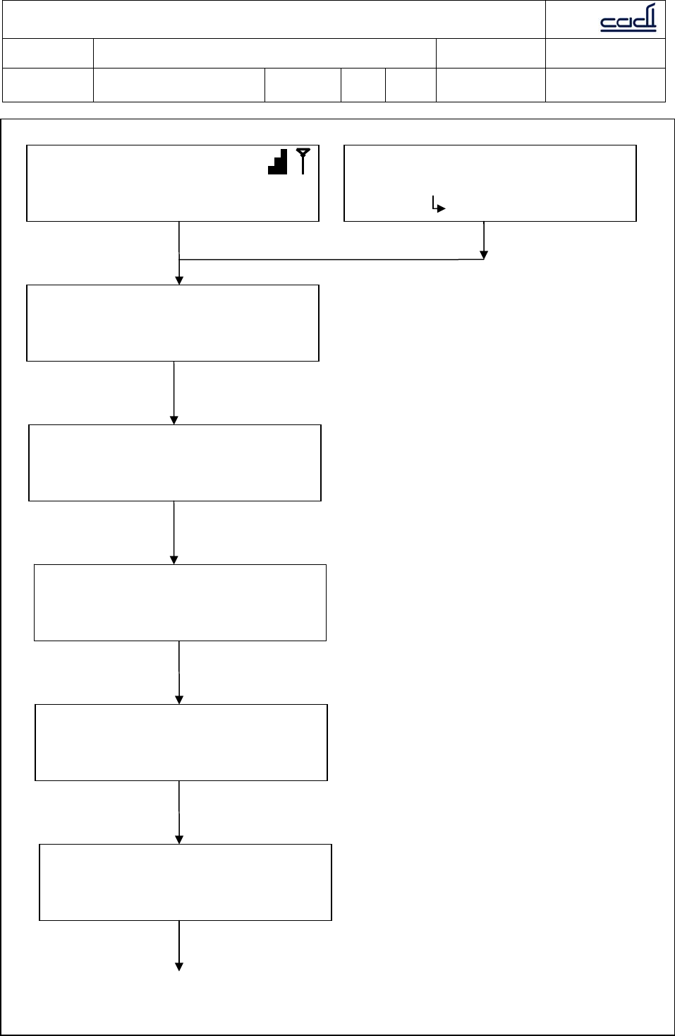
3.3 Setting up the device
There are some settings to be done before CADI SMB-800 can be used. A few statistics
can also be viewed. The figure below shows the menus available to the user. These can
be accessed using the Menu button and Select button to navigate.
The menus available are:
1. Alarm On/Off, Volume
2. Port x Device (nothing to set)
4. Upload Mode Manual/Auto
5. Set Interval Hours, Minutes (for Auto mode only)
5. Date setting dd/mth/yy/day of week
6. Time setting hh:mm, AM/PM
7. Readings saved Number of records stored (nothing to set)
8. Maintenance mode (password protected, for service personnel only)
C
Ca
ad
di
i
S
Sc
ci
ie
en
nt
ti
if
fi
ic
c
P
Pt
te
e
L
Lt
td
d
Document: Quality Objectives and Quality Planning Control
Procedures Document No.: MDDQP-001-A2
Dept. of
preparation: Management
Representative Revision: B01 Issue
Date: 28 Oct 2009 Page 18 of 29
Annex II
07/SEP/09
Scan ID to Start
ID: S90lP06YA
Press to Abort
-PORT 1 DEVICE-
VS300
-PORT 2 DEVICE-
VS300
-PORT 3 DEVICE-
VS300
-PORT 4 DEVICE-
VS300
-ALARM-
ON Vol:01
Press Menu button
Press Menu button
Press Menu button
Press Menu button
Press Menu button
C
Ca
ad
di
i
S
Sc
ci
ie
en
nt
ti
if
fi
ic
c
P
Pt
te
e
L
Lt
td
d
Document: Quality Objectives and Quality Planning Control
Procedures Document No.: MDDQP-001-A2
Dept. of
preparation: Management
Representative Revision: B01 Issue
Date: 28 Oct 2009 Page 19 of 29
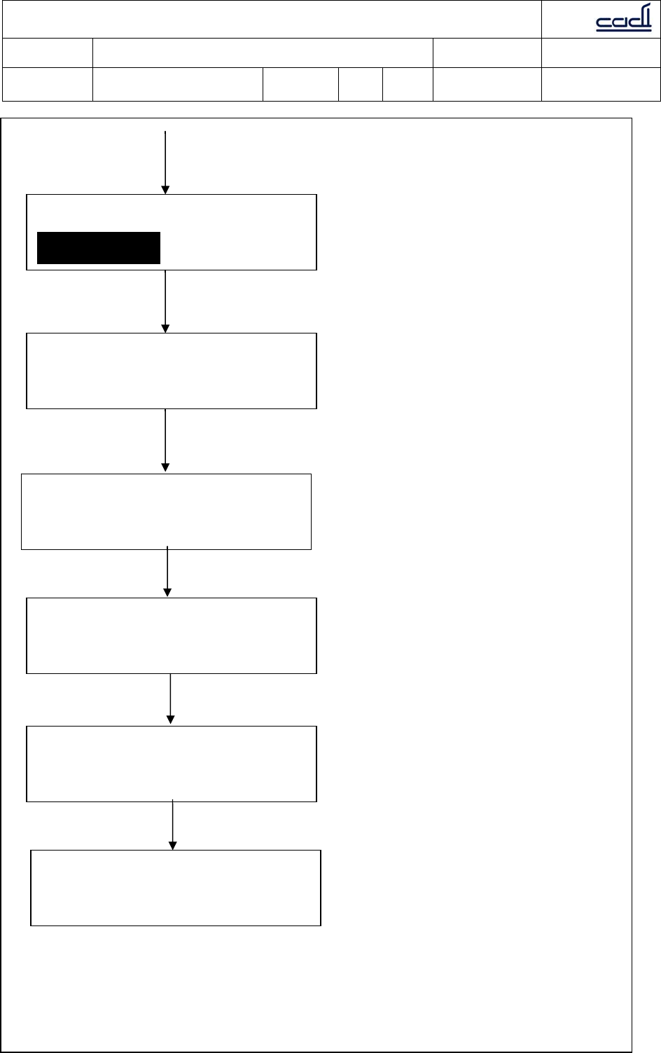
Annex II
UPLOAD MODE
MANUAL
Set Interval
0Hours 30Minutes
-DATE-
07/SEP/2010 THU
-TIME-
02:38 PM
-Readings saved-
1000 set saved
-MAINTENANCE-
ENTER
Press Menu button
Press Menu button
Press Menu button
Press Menu button
Press Menu button
Press Menu button
Note: For AUTO mode only
C
Ca
ad
di
i
S
Sc
ci
ie
en
nt
ti
if
fi
ic
c
P
Pt
te
e
L
Lt
td
d
Document: Quality Objectives and Quality Planning Control
Procedures Document No.: MDDQP-001-A2
Dept. of
preparation: Management
Representative Revision: B01 Issue
Date: 28 Oct 2009 Page 20 of 29
Annex II
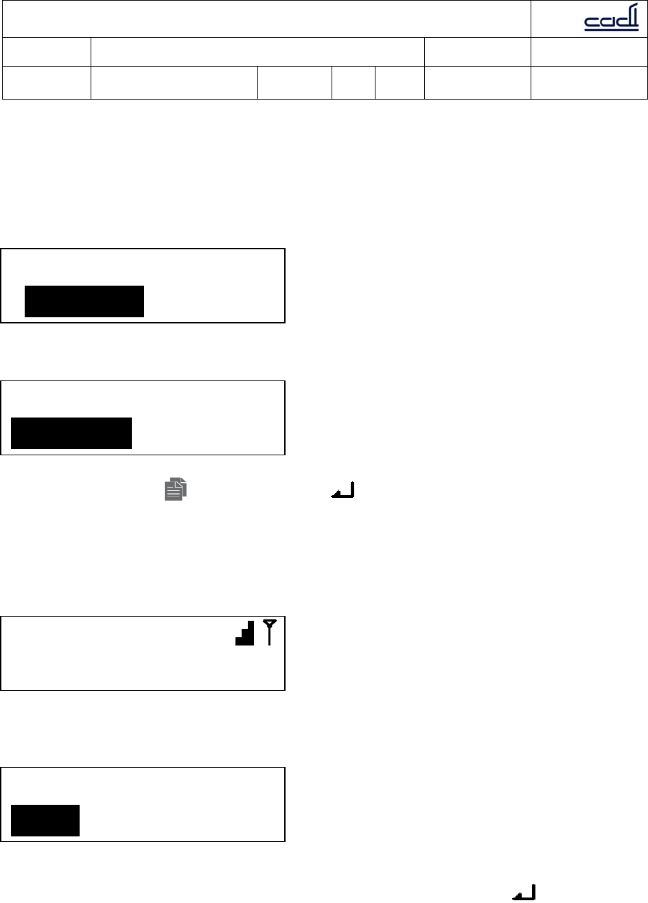
3.4 Using the device
CADI SMB-800 has two modes of operation: 1. MANUAL mode; 2. AUTO mode.
Both can be entered upon power up or by menu navigation.
Upon power up:
Using menu navigation:
Use the Menu button and Select button to navigate.
3.4.1 Manual mode
Manual mode is used for spot measurement. Once Manual mode is selected, the
“Manual” word will light up and the LCD will show the following screen:
Before each measurement, the user has to scan the ID with the barcode scanner. Once
the barcode is scanned, the next screen will show:
After this, activate the attached medical device (refer to the appropriate user manual). If
at any time the user wants to abort, just select ESC and press button here.
Otherwise, navigate to SAVE to save and upload reading, or REVIEW to look at the
results.
Set Mode
MANUAL AUTO
07/SEP/09
Scan ID to start
ID: S90lP06YA
SAVE REVIEW ESC
UPLOAD MODE
MANUAL
C
Ca
ad
di
i
S
Sc
ci
ie
en
nt
ti
if
fi
ic
c
P
Pt
te
e
L
Lt
td
d
Document: Quality Objectives and Quality Planning Control
Procedures Document No.: MDDQP-001-A2
Dept. of
preparation: Management
Representative Revision: B01 Issue
Date: 28 Oct 2009 Page 21 of 29
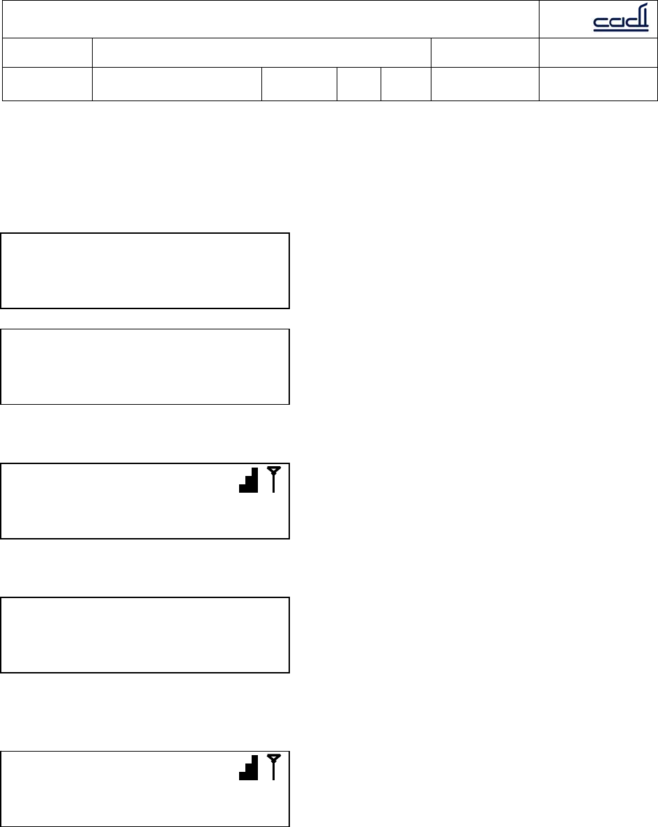
Annex II
SAVE is selected: The LCD will display upload progress bar. Upload status (upload fail or
success) will be shown on screen.
REVIEW is selected: The LCD will display the readings and option to SAVE or DISCARD
reading.
ESC is selected: last measurement is discarded and screen returns to default display:
If something did not go smoothly, the screen below will flash:
If everything goes as normal and the measurement is successfully completed, the next
screen will return to the default display:
07/SEP/09
Scan ID to start
NO MEASUREMENT
Save Measurement?
Save Abort
√P1: SYS 120
√P1: DIA 80
07/SEP/09
Scan ID to Start
C
Ca
ad
di
i
S
Sc
ci
ie
en
nt
ti
if
fi
ic
c
P
Pt
te
e
L
Lt
td
d
Document: Quality Objectives and Quality Planning Control
Procedures Document No.: MDDQP-001-A2
Dept. of
preparation: Management
Representative Revision: B01 Issue
Date: 28 Oct 2009 Page 22 of 29
Annex II
3.4.2 Auto mode
Auto mode is used for single patient use e.g. bedside monitoring. When using Auto mode,
make sure the connected medical device is also set to Auto mode (refer to the respective
user manuals). Once Auto mode is selected, the “Auto” word will light and the LCD will
show the following screen:
The user can set the interval for data upload here. Use the Menu button for
changing the values and Select button for confirmation. This setting is stored in
non-volatile memory. Upon confirmation, the next screen will show the default display:
Once the ID has been scanned via the barcode scanner, the next screen will show:
If the connected medical devices have also been set for Auto mode, no further action is
necessary. The device will activate measuring at the specified interval.
ID: S90lP06YA
SAVE REVIEW ESC
07/SEP/09
Scan ID to Start
Set Interval
0Hours 30Mins
C
Ca
ad
di
i
S
Sc
ci
ie
en
nt
ti
if
fi
ic
c
P
Pt
te
e
L
Lt
td
d
Document: Quality Objectives and Quality Planning Control
Procedures Document No.: MDDQP-001-A2
Dept. of
preparation: Management
Representative Revision: B01 Issue
Date: 28 Oct 2009 Page 23 of 29
Annex II
3.5 MAINTENANCE
C
Ca
ad
di
i
S
Sc
ci
ie
en
nt
ti
if
fi
ic
c
P
Pt
te
e
L
Lt
td
d
Document: Quality Objectives and Quality Planning Control
Procedures Document No.: MDDQP-001-A2
Dept. of
preparation: Management
Representative Revision: B01 Issue
Date: 28 Oct 2009 Page 24 of 29
Annex II
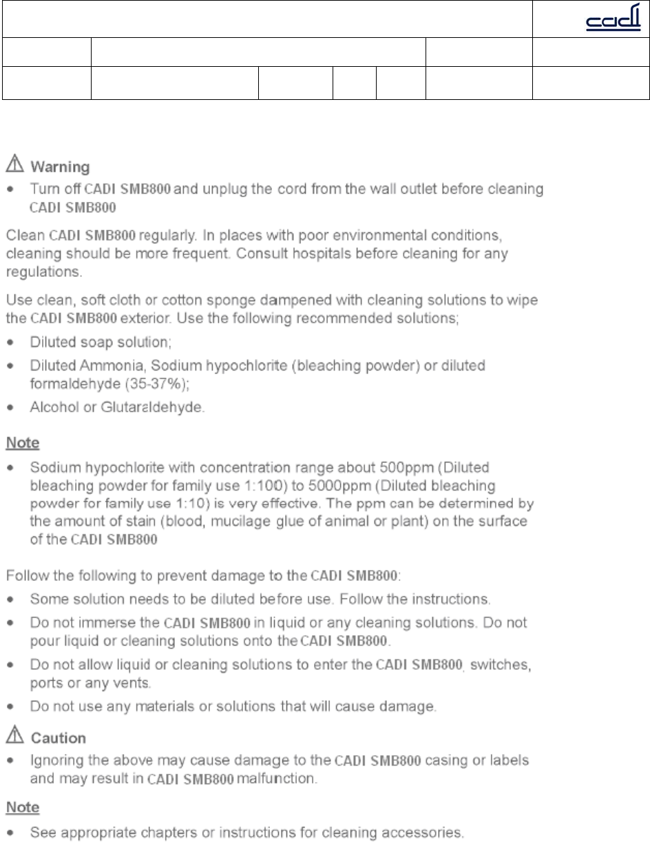
3.5.2 Cleaning
C
Ca
ad
di
i
S
Sc
ci
ie
en
nt
ti
if
fi
ic
c
P
Pt
te
e
L
Lt
td
d
Document: Quality Objectives and Quality Planning Control
Procedures Document No.: MDDQP-001-A2
Dept. of
preparation: Management
Representative Revision: B01 Issue
Date: 28 Oct 2009 Page 25 of 29
Annex II
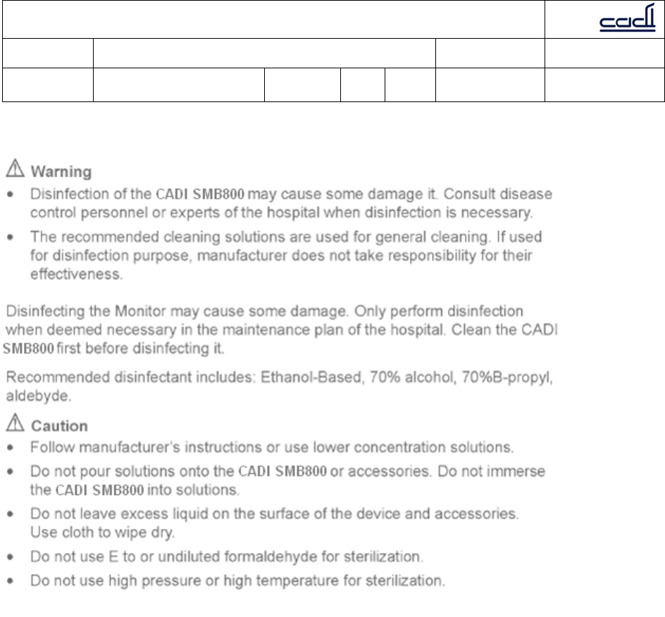
3.5.3 Disinfection

C
Ca
ad
di
i
S
Sc
ci
ie
en
nt
ti
if
fi
ic
c
P
Pt
te
e
L
Lt
td
d
Document: Quality Objectives and Quality Planning Control
Procedures Document No.: MDDQP-001-A2
Dept. of
preparation: Management
Representative Revision: B01 Issue
Date: 28 Oct 2009 Page 26 of 29
Annex II
4. ALARM
4.1 OVERVIEW
Alarms are audio and visual indicators generated by the CADI SMB-800 to alert doctors
and nurses. These alarms occur when the vital signs of the patients being monitored
become abnormal or the CADI SMB-800 itself malfunctions and cannot perform its task.
4.1.1 Alarm types
The alarms are Technical Alarm and Information Prompt.
Technical Alarm
Technical Alarm means the device or parts are not capable to perform the monitoring
task, e.g. device failure.
Information Prompt
Strictly speaking, Information Prompt is not a type of alarm. The CADI SMB-800 can
display some information of the system status, e.g. battery low. This type of
information is not related to device failure.
4.1.2 Alarm levels
There are 3 levels of alarm: High, Mid and Low.
High level alarm
High level alarm indicates life threatening or serious technical problems of the CADI
SMB-800.
Mid level alarm
Mid level alarm occurs when preset thresholds are exceeded.
Low level alarm
The following situations will prompt low level alarms:
1. CADI SMB-800 malfunction;
2. Battery low (when using battery for power supply);
3. Medical device connection lost.
When battery is low, the indicator will illuminate and there will be sound. All Technical
Alarms are default settings which cannot be changed.

C
Ca
ad
di
i
S
Sc
ci
ie
en
nt
ti
if
fi
ic
c
P
Pt
te
e
L
Lt
td
d
Document: Quality Objectives and Quality Planning Control
Procedures Document No.: MDDQP-001-A2
Dept. of
preparation: Management
Representative Revision: B01 Issue
Date: 28 Oct 2009 Page 27 of 29
Annex II
4.1.3 Alarm modes
The alarm modes are:
1. Audio alarm;
2. Visual alarm;
3. Information alarm.
These alarm modes indicate alarm levels differently.
4.2 AUDIO ALARM
Audio alarm includes alarm sound, key pressing sound and pulse sound.
Note
When various levels of alarm occur at the same time, alarm sound indicates the high
level alarm.
Table 4-1 Alarm Sound Functions
Function Explanation Volume Frequency
(Hz) Width
Td(ms) Interval
Ts(ms) Number of sounds
Self test
passed Power-on self
test completed,
one sound
indicates the
test passed.
Cannot be
adjusted 1500 150 N/A One “beep”
Valid key
pressing One sound
indicates the
key pressing is
valid.
Cannot be
adjusted 400 150 N/A One “beep”
High level
alarm One high note
sound with
rapid “beep”
Adjustable 700 150 N/A “beep-beep-beep—
beep-beep, beep-
beep-beep—beep-
beep”
Mid level
alarm Two mid, stable
beeps Adjustable 700 150 200 “beep-beep-beep”
Low level
alarm One low, slow
beep Adjustable 700 150 N/A One “beep”
C
Ca
ad
di
i
S
Sc
ci
ie
en
nt
ti
if
fi
ic
c
P
Pt
te
e
L
Lt
td
d
Document: Quality Objectives and Quality Planning Control
Procedures Document No.: MDDQP-001-A2
Dept. of
preparation: Management
Representative Revision: B01 Issue
Date: 28 Oct 2009 Page 28 of 29
Annex II
4.3 VISUAL ALARM
Yellow light is used for visual alarms. 2Hz flashing yellow light indicates
communication error and battery low. Other alarms do not have flashing light.
4.4 ALARM SETTINGS
4.5 AUDIO ALARM STATUS
Under normal working conditions, all alarm modes for all levels of alarms can be
performed. The user can also set alarms to meet their requirements. The alarm
settings can be accessed from the menu. Note that High level alarms cannot be
disabled.
Normal audio alarms
When alarms occur, there is a normal alarm sound.
Alarm sound setting
Alarm sound OFF means the sound is silenced. Under the menu, navigate to Alarm
screen and select OFF.
-ALARM-
OFF Vol:01
C
Ca
ad
di
i
S
Sc
ci
ie
en
nt
ti
if
fi
ic
c
P
Pt
te
e
L
Lt
td
d
Document: Quality Objectives and Quality Planning Control
Procedures Document No.: MDDQP-001-A2
Dept. of
preparation: Management
Representative Revision: B01 Issue
Date: 28 Oct 2009 Page 29 of 29
Annex II
SPECIFICATIONS
Power 100 - 240 V AC, 50/60 Hz
Power consumption Max 40VA
External dimensions
(excluding maximum
projecting
part)
170 x 280 x 40 mm
Internal battery pack 12.6v Li-Ion (SHENZHEN CHAM BATTERY
CMICR18650)
Clock backup battery 3v Li-Mn cell CR2450
Mass Approx. 1.2 kg (2.6 lb)
Operating
temperature 20°C - 40°C (68°F - 104°F)
Storage temperature 10°C - 50°C (50°F - 122°F)
Transport temperature 10°C - 50°C (50°F - 122°F)
Inputs/outputs DC connector x1
DB9F x4
Supplied accessories DC adapter x1 (SKYNET SNP-A048-M)
AC cable x1
DB9 cable x1
Instruction manual x1
Transmission
frequency 868.4 MHz (For customer in Europe)
919.8 MHz (For customer in U.S.A)
925.0 MHz (For customer in U.S.A)
2.4 Ghz (For customer in Europe and U.S.A)