CalAmp Wireless Networks 1409290100 900 MHz Broadband Base Station User Manual install guide
CALAMP WIRELESS NETWORKS INC. 900 MHz Broadband Base Station install guide
Contents
- 1. antenna information
- 2. operating manual
- 3. install guide
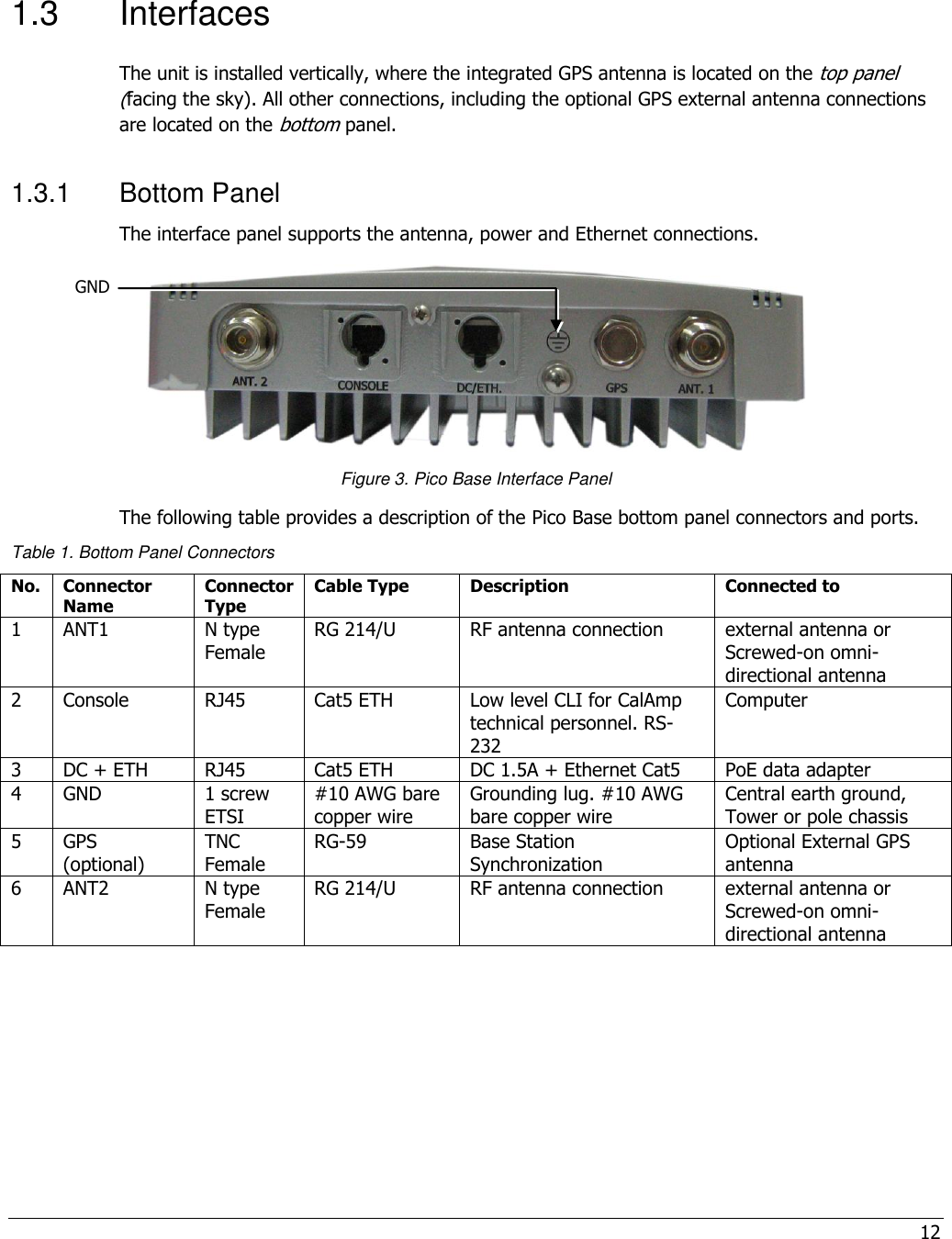
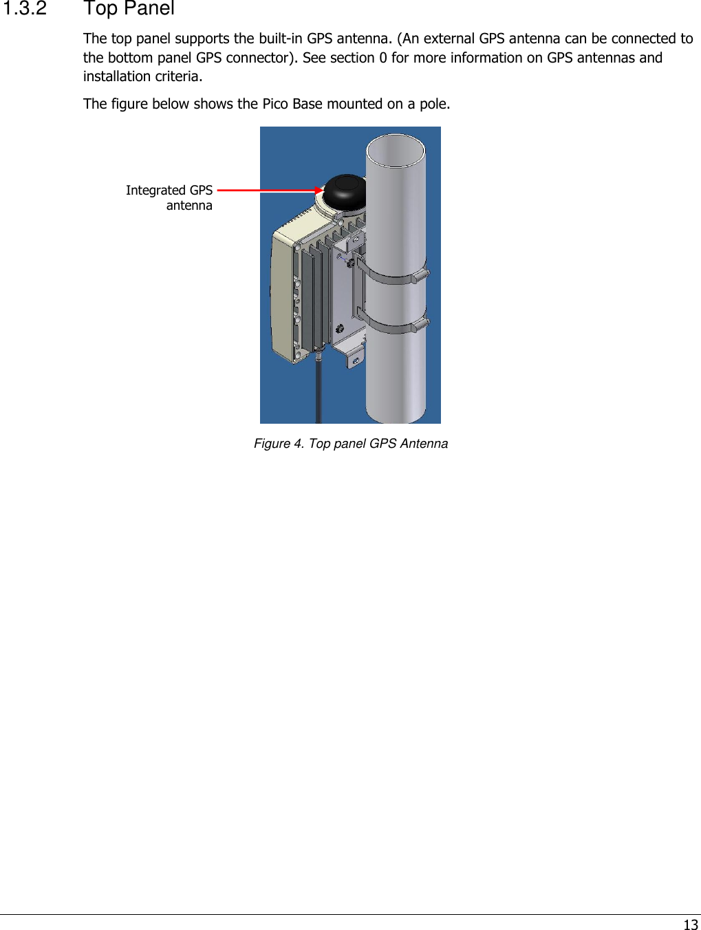
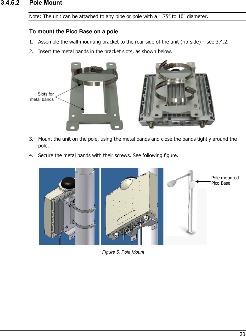
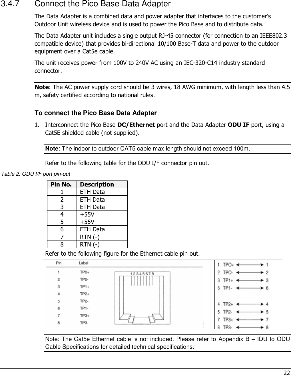
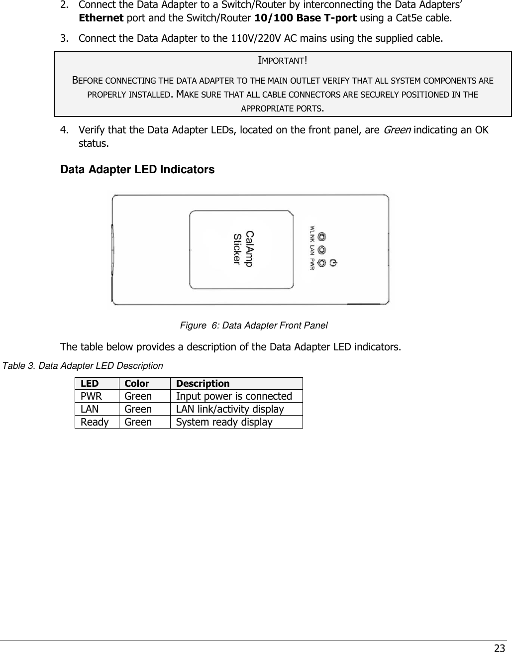
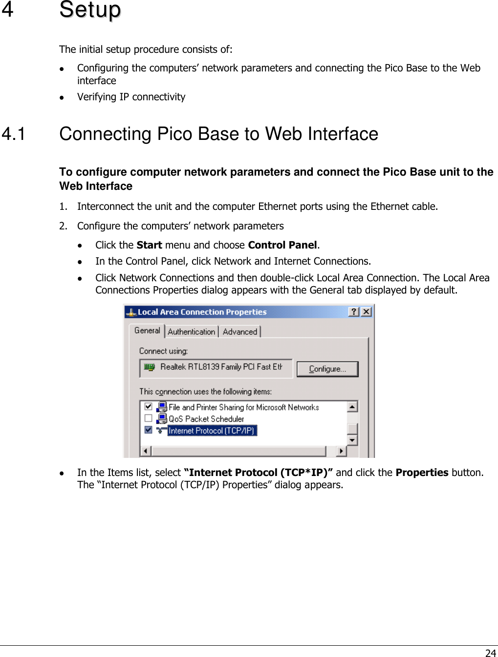
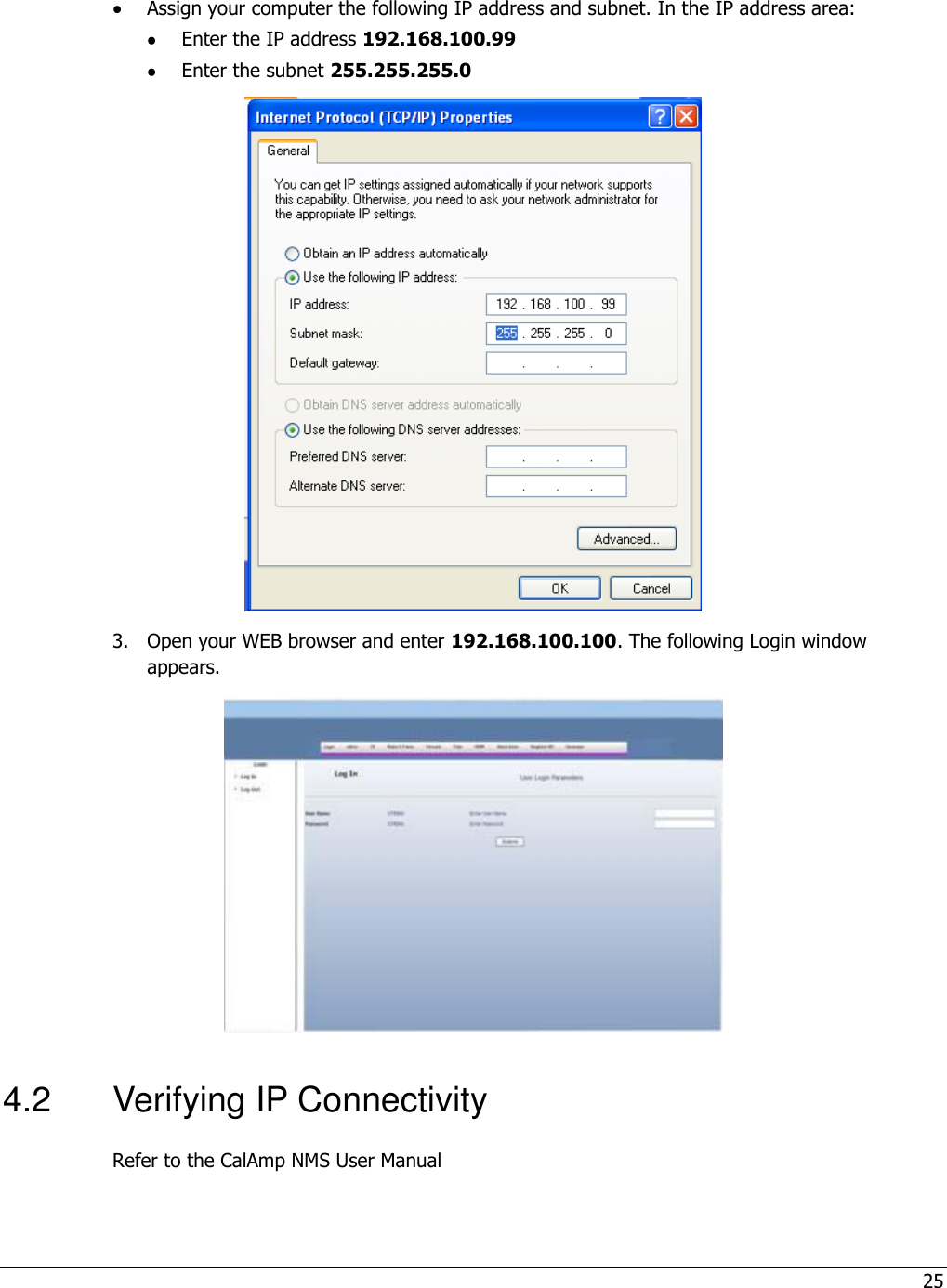
install guide


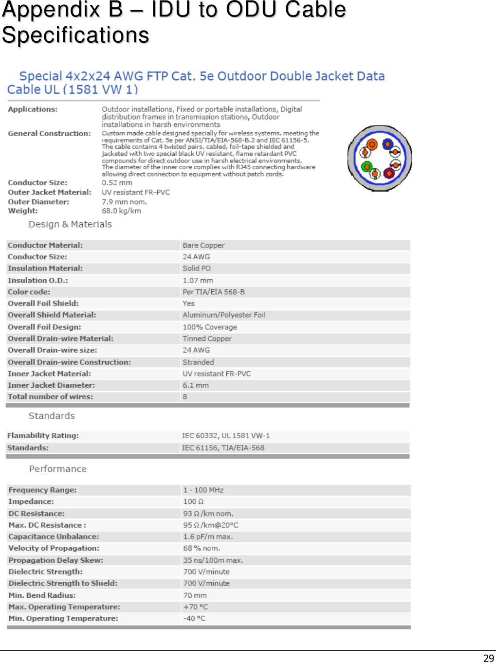
![27 AAppppeennddiixx AA –– SSppeecciiffiiccaattiioonnss Radio and Modem Frequency 903.90-926.10 MHz for 3.5 MHz Channels 904.65-925.30 MHz for 5 MHz Channels 905.75-924.20 MHz for 7 MHz Channels 907.25-922.70 MHz for 10 MHz Channels Radio Access Method IEEE802.16-2005 (16e OFDMA) Operation Mode TDD Channel Bandwidth 3.5Mhz, 5 MHz, 7Mhz, 10 MHz Frequency Resolution 0.25 MHz Antennas Integral Omni (default) Number of Antennas 2 Default Antenna Omni Antennas Connectors 2x N-Type, 50 ohm, lightning protected Diversity Support 2x2, STC/MIMO-SM Output Power [P1dB] 2 x 5W; Output Power (average) 27 dBm +/-1dB maximum FFT/Modulation 512/1024 FFT points; QPSK, 16QAM, 64QAM FEC Convolution Code and Turbo Code TPC 10dB Synchronization GPS or IEEE1588 (optional) Configuration and Management Management SNMP SNMP Agent SNMP ver 2 client: MIB II (RFC 1213), Private MIBs Software Upgrade FTP Remote Configuration FTP Power Interface Input 37-56VDC Power Consumption 45Watt maximum Environmental Operating Temperature -40 C to +55 C Operating Humidity 5%-95% non condensing, Weather protected Standards and Compliances EMC FCC part 15, subpart B, class B ETSI EN 301489-1/4 Safety TUV-UL 60950-1 IEC 61950-1 Environmental ETS 300 019: Part 2-1 T 1.2 & part 2-2 T 2.3 Part 2-4 T 4.1E](https://usermanual.wiki/CalAmp-Wireless-Networks/1409290100.install-guide/User-Guide-1278540-Page-27.png)
![28 Enclosure Type3R (IP66) Immunity EN61000-4-2 EN61000-4-4 EN61000-4-5 Radio FCC Part 15 Subpart C Industry Canada RSS-210 ETSI EN302 326 Mechanical Dimensions [HxWxD] 24cm x 20cm x 4cm Weight <4Kg](https://usermanual.wiki/CalAmp-Wireless-Networks/1409290100.install-guide/User-Guide-1278540-Page-28.png)