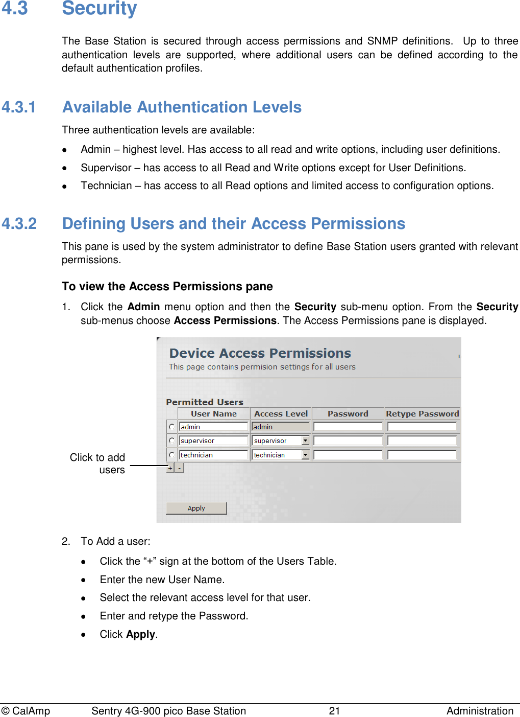
CalAmp Wireless Networks 1409290100 900 MHz Broadband Base Station User Manual operating manual
CALAMP WIRELESS NETWORKS INC. 900 MHz Broadband Base Station operating manual
Contents
- 1. antenna information
- 2. operating manual
- 3. install guide
operating manual
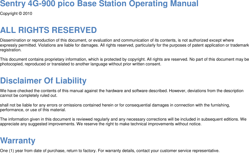
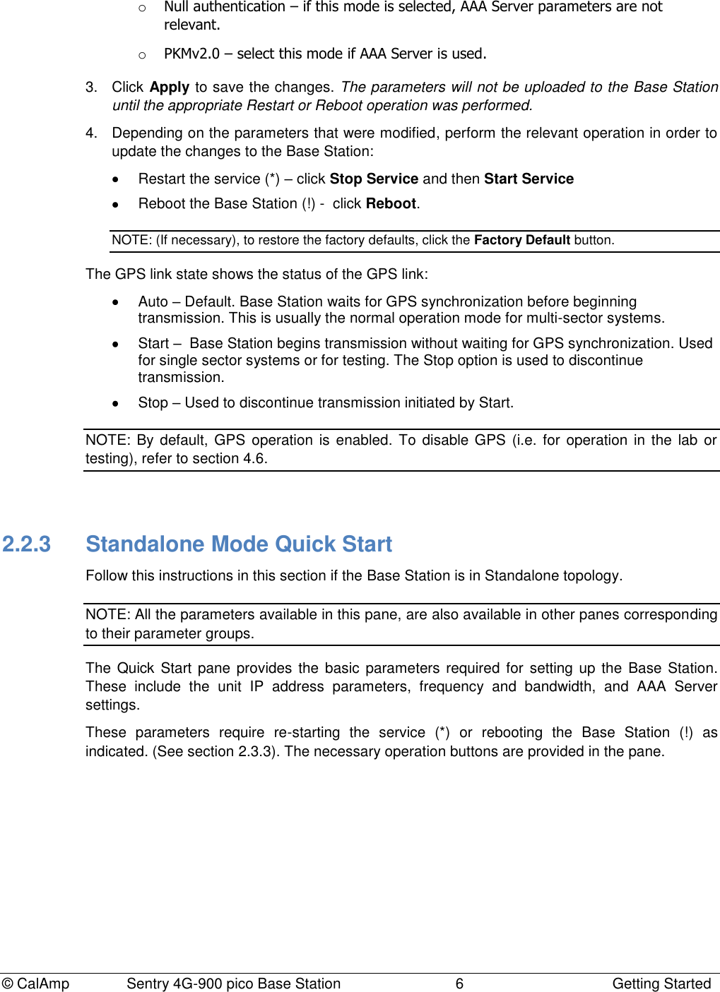
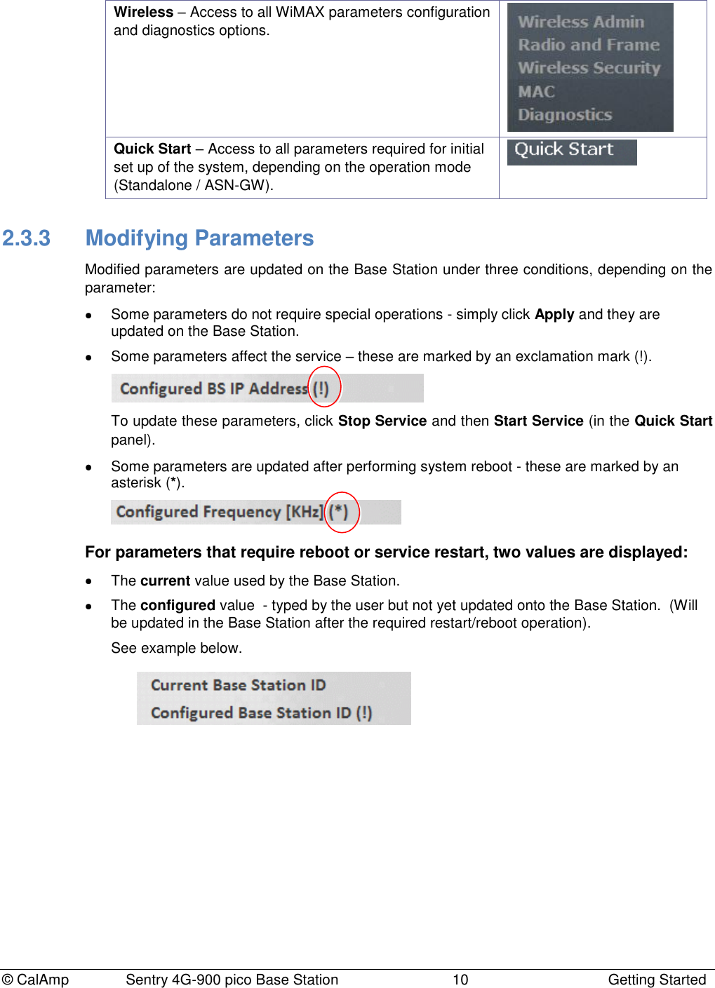
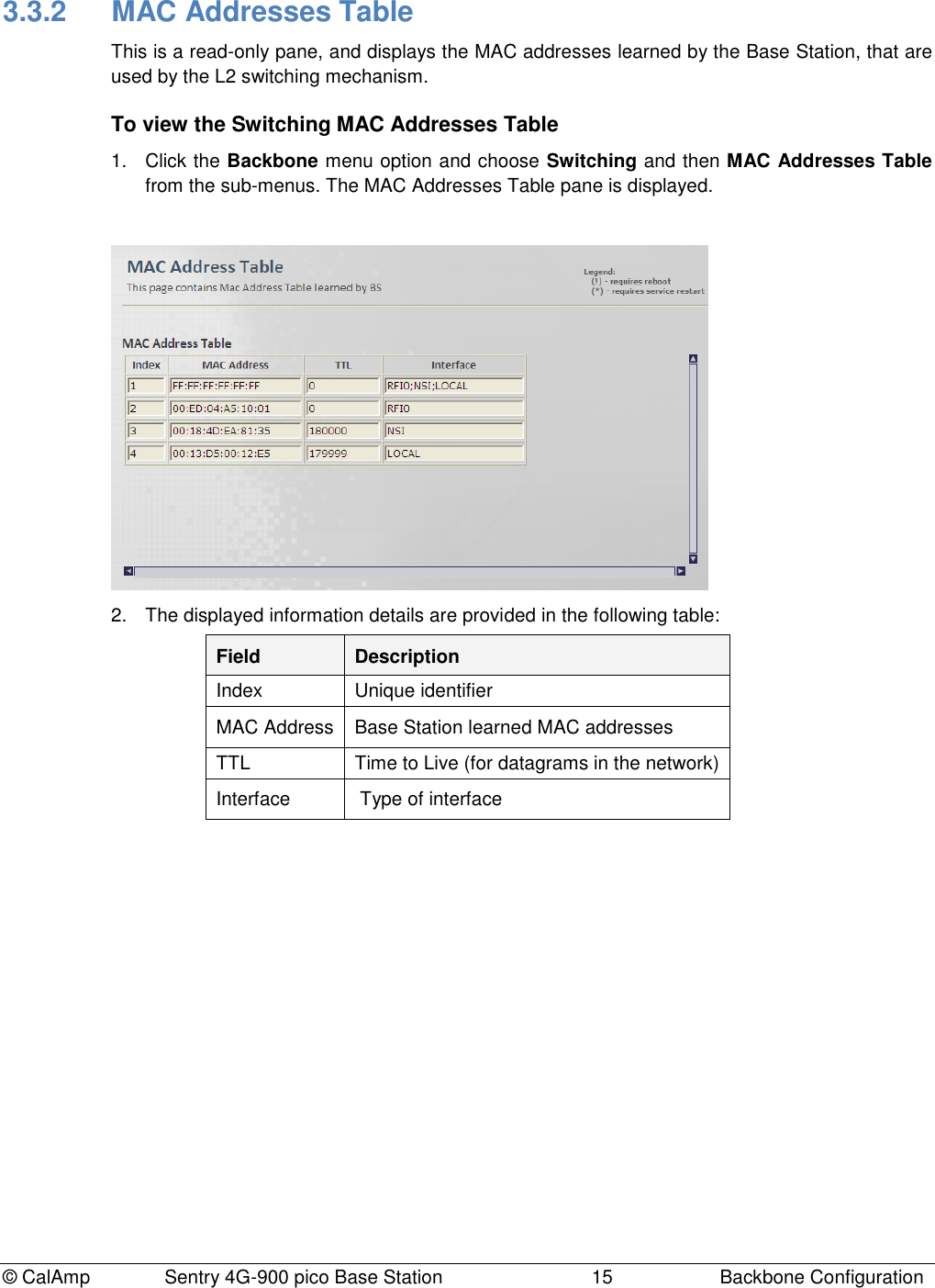
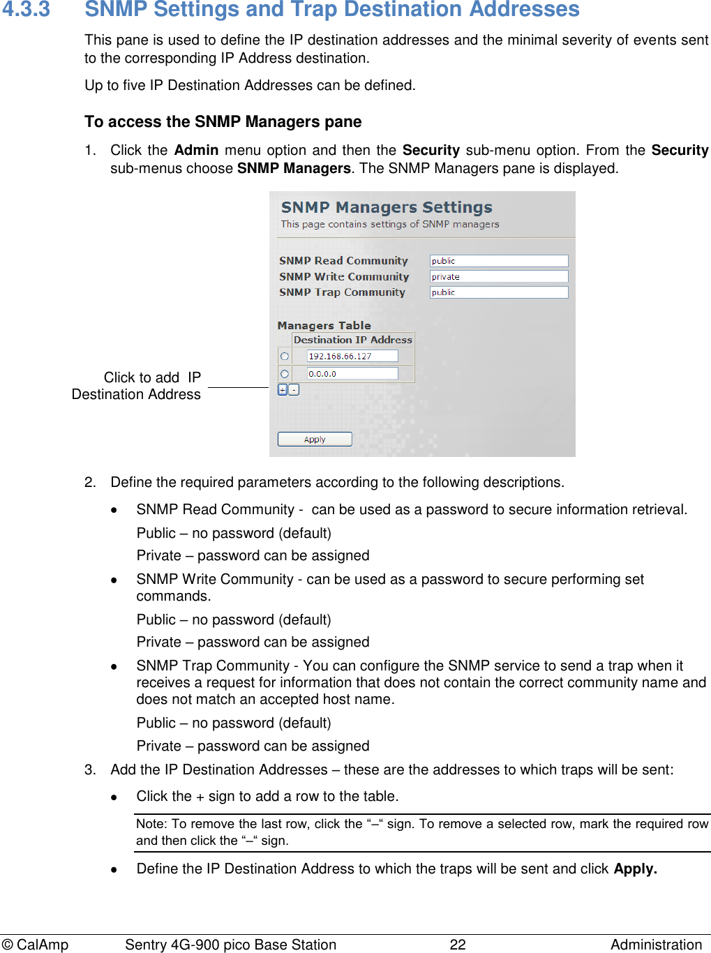
![© CalAmp Sentry 4G-900 pico Base Station 14 Backbone Configuration 3.3.1 Switching Settings This pane provides configuration options for the L2 Switching mode and for the MAC address aging period. To access the Switching Settings pane 1. Click the Backbone menu option and choose Switching and then Switching Settings from the sub-menus. The Switching settings pane is displayed. 2. Define the required parameters according to the following descriptions and click Apply. Field Description Current/Configured Switching Mode This parameter defines the traffic forwarding method: L2 Switching mode: traffic flooding is enabled. To dynamically learn about station locations, the Base Station listens to incoming frames and keeps a table of address information by inspecting the source MAC addresses. If the source MAC address is not in the address table already, it is recorded in the table. As a part of the forwarding decision, if destination MAC address is found, the frame can be forwarded to that address. If the address is not found in the table, the frame is flooded to all the CPEs (if it's a downlink packet) and to the CPEs and network interface (if it's an uplink packet). Forward-to-router mode (To be used for testing purposes only!!!): all traffic is forwarded to the upstream router (no flooding). Do NOT use it. Values: [L2 Switching; Forward-to-router] MAC address Table Aging Time (300…1800) [sec] Mac Address Table Aging period (in seconds), after which unused MAC address entries will be dropped. Values: 300-1800](https://usermanual.wiki/CalAmp-Wireless-Networks/1409290100.operating-manual/User-Guide-1278539-Page-18.png)
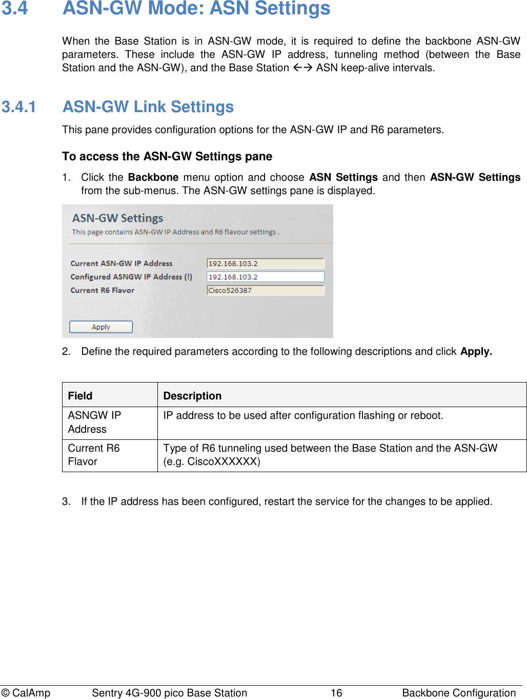
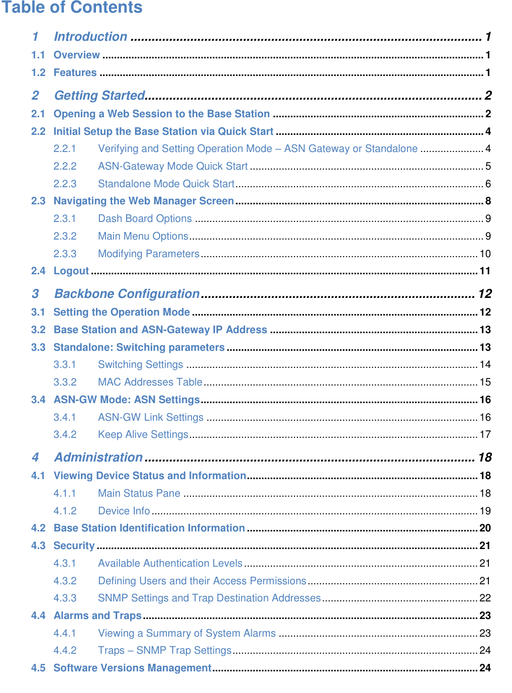
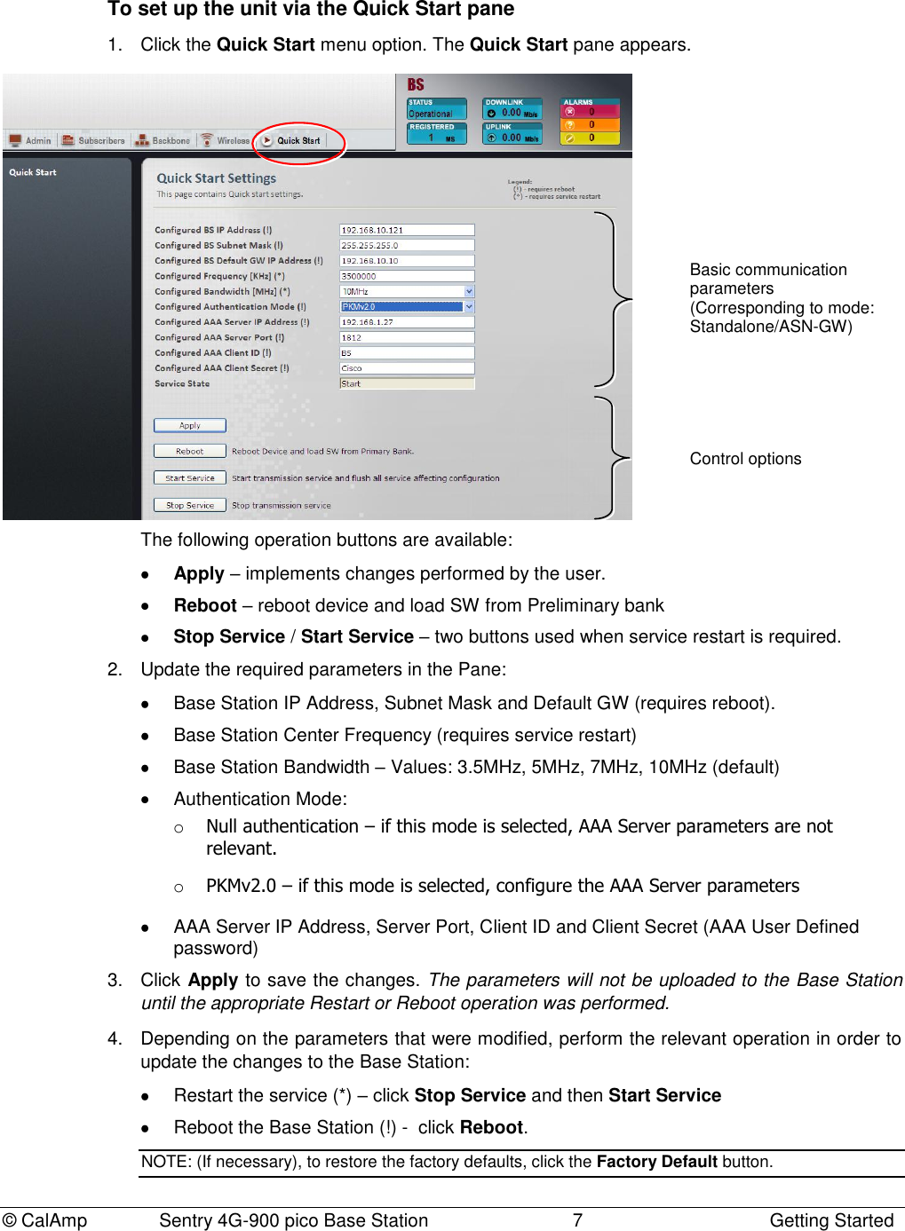
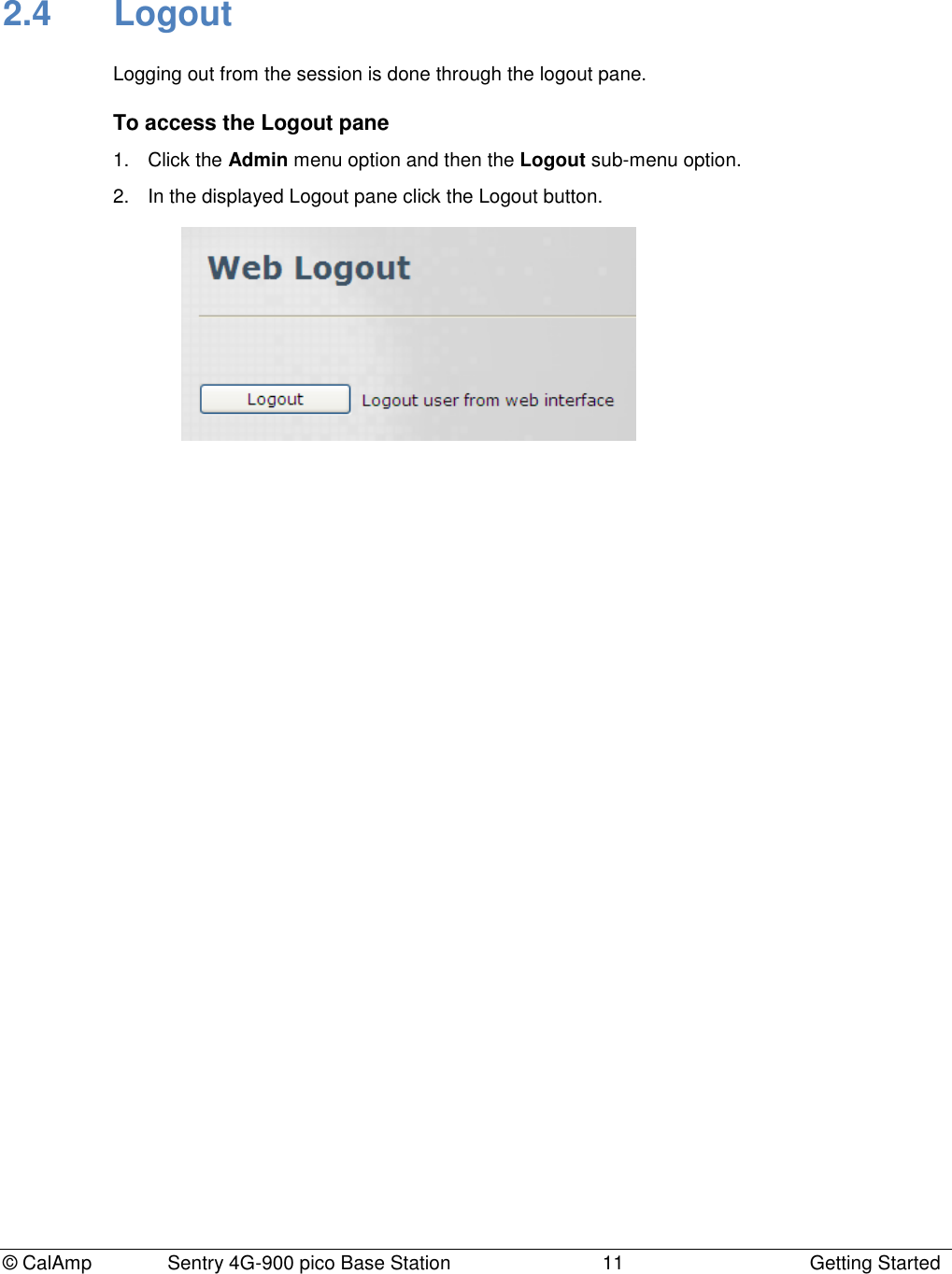
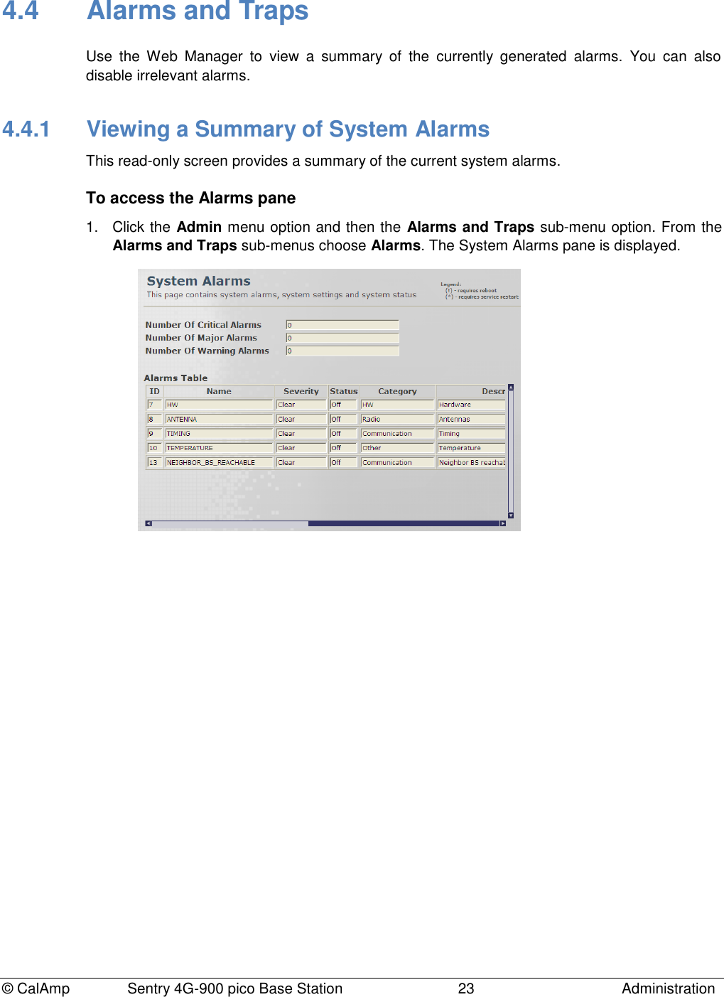
![© CalAmp Sentry 4G-900 pico Base Station 17 Backbone Configuration 3.4.2 Keep Alive Settings This pane provides configuration options for the keep-alive messages intervals and retries protocol. To access the Keep Alive Settings pane 1. Click the Backbone menu option and choose ASN Settings and then Keep Alive Settings from the sub-menus. The Keep Alive settings pane is displayed. 2. Define the required parameters according to the following descriptions and click Apply. Field Description Keep Alive timeout (10000..180000) [µs] This value indicates the time interval (in µSec) that a Base Station waits for the keep-alive response before keep-alive request re-transmission. Keep Alive Retries (1..10) Max number of keep-alive re-transmissions Keep Alive Activation Mode Enable / Disable Keep Alive activation. Values: [True, False] 3. If the Keep Alive Activation Mode has been configured, reboot the Base Station for the changes to be applied.](https://usermanual.wiki/CalAmp-Wireless-Networks/1409290100.operating-manual/User-Guide-1278539-Page-21.png)
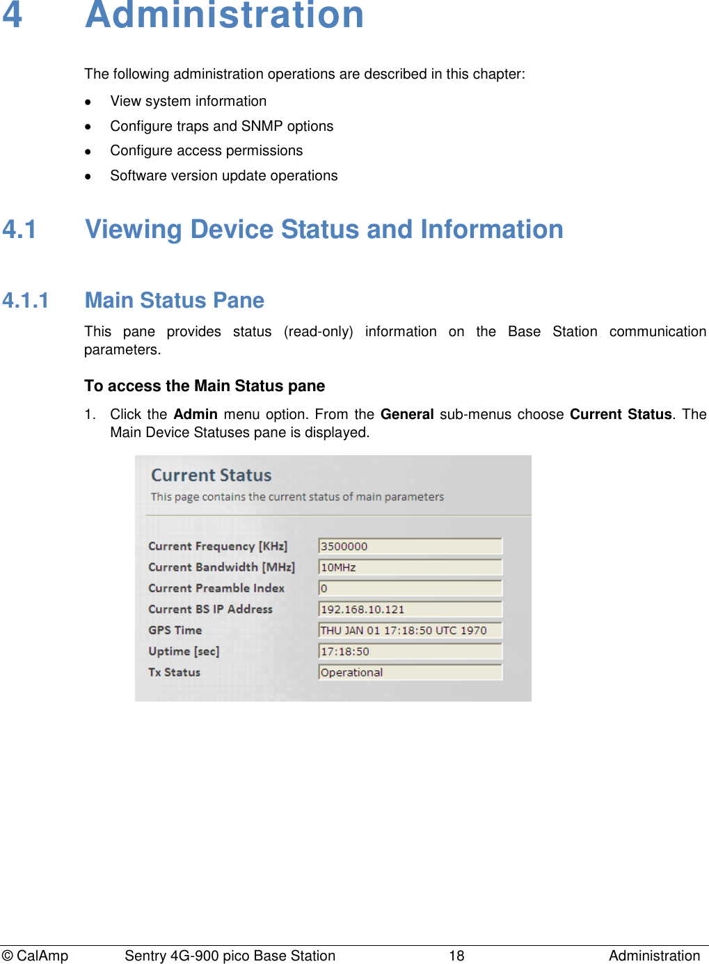
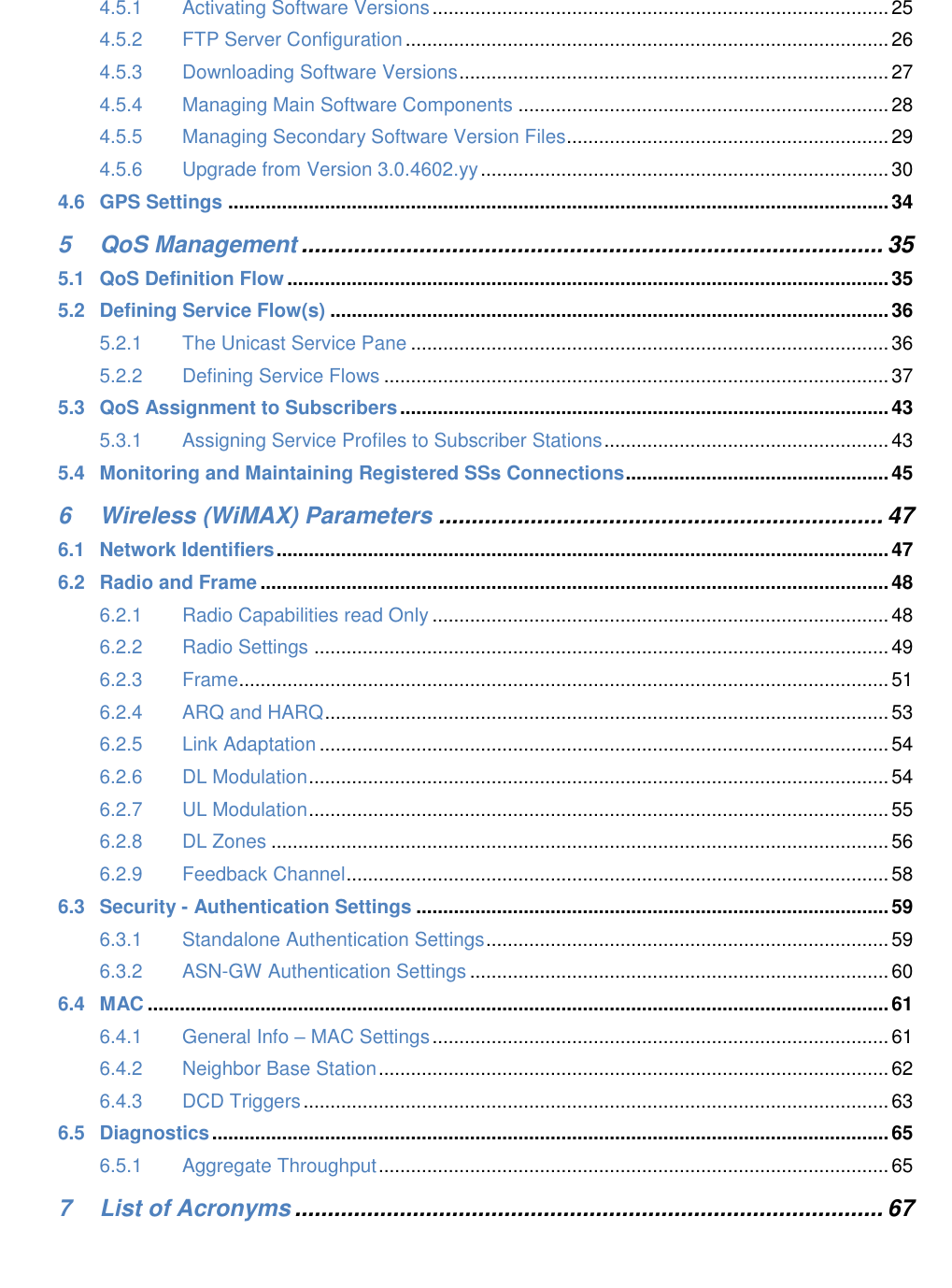
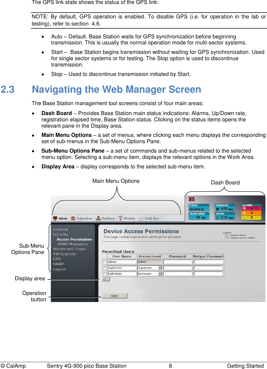
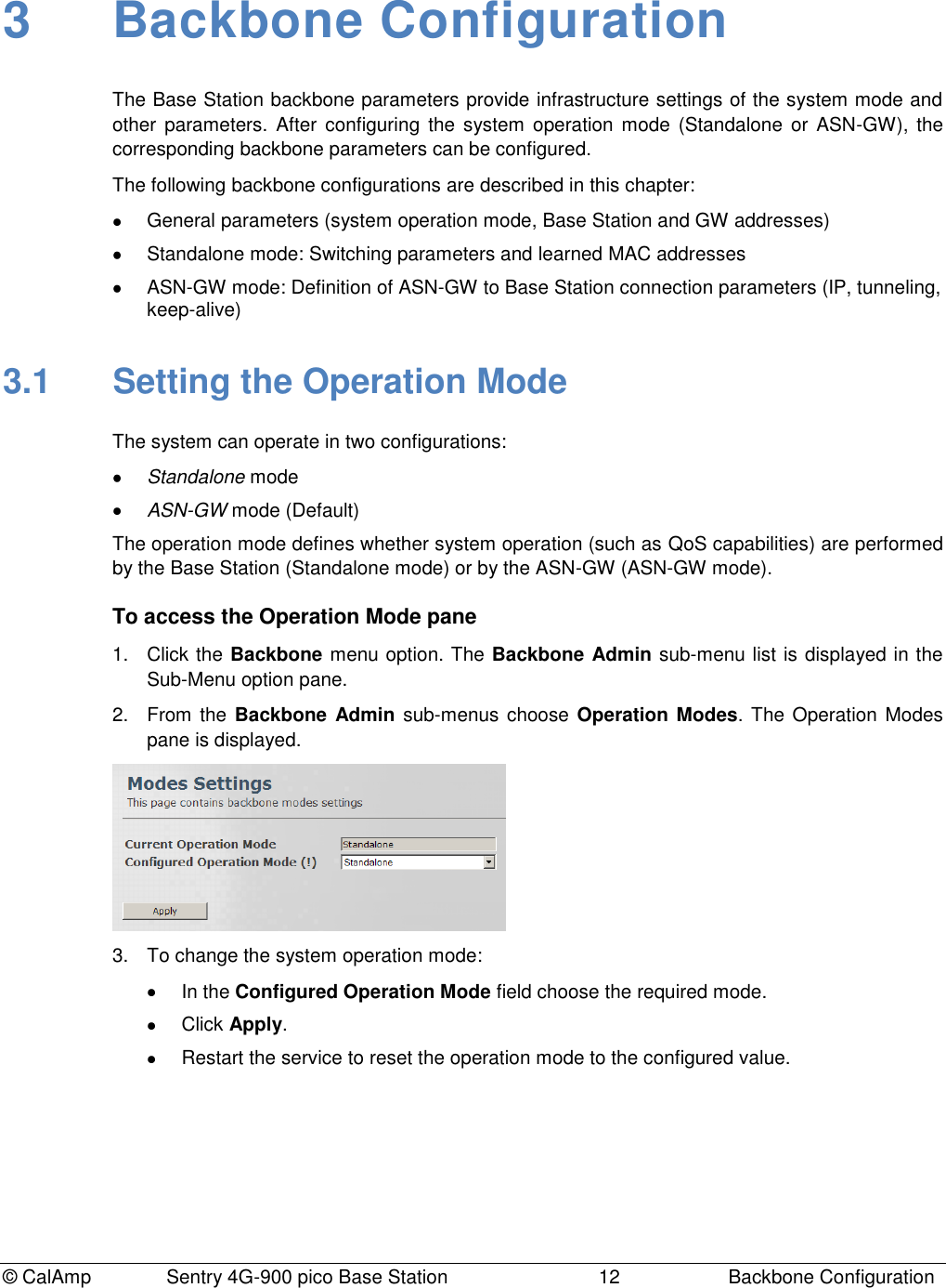
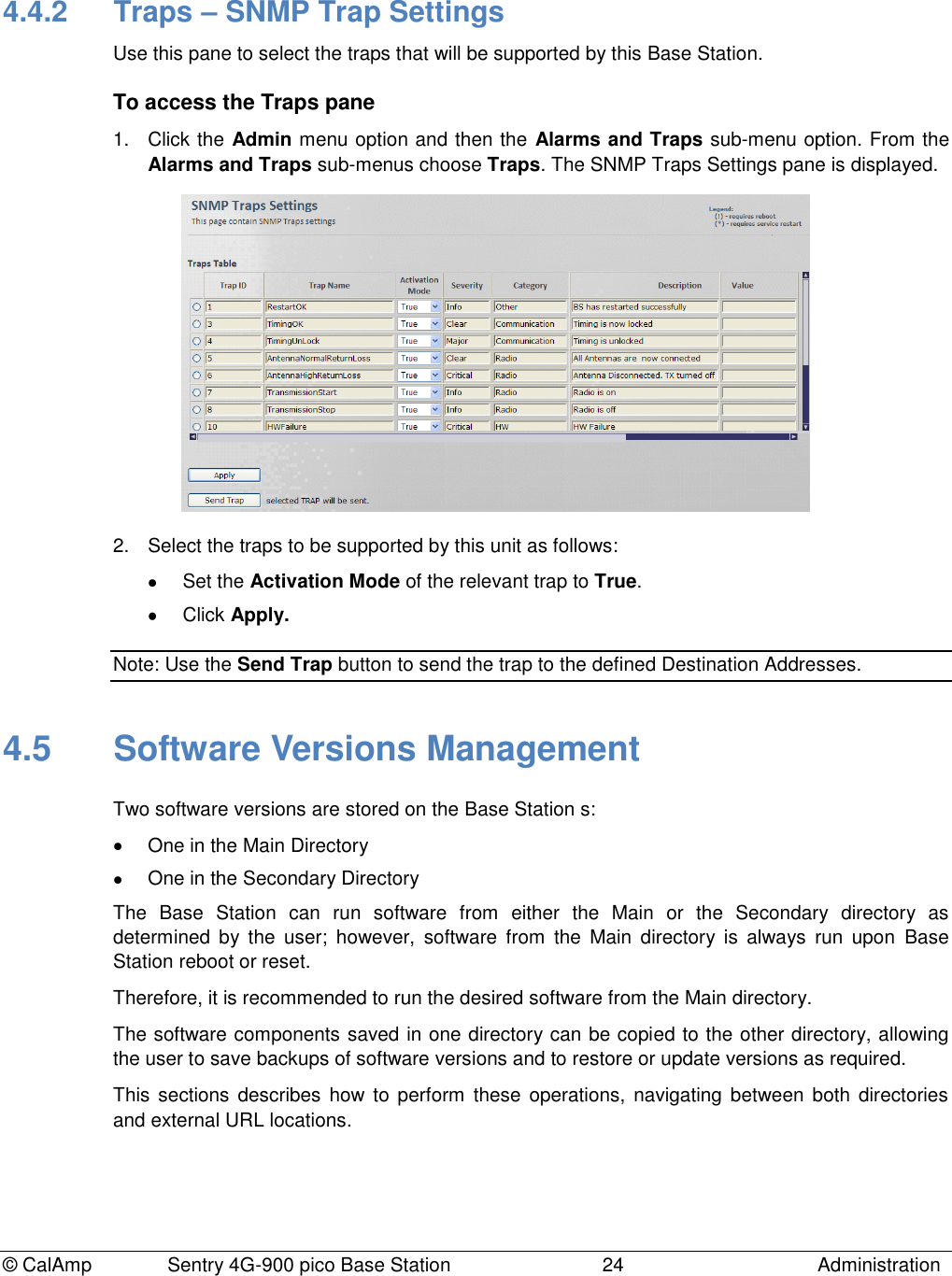
![© CalAmp Sentry 4G-900 pico Base Station 19 Administration 2. The displayed information details are provided in the following table: Field Description Current Frequency [KHz] Current Frequency in KHz Current Bandwidth [MHz] Current Operative BW in Mhz; Must be one of the supported BWs Current Preamble Index Current Operative Preamble Index Current Base Station IP Address Current Base Station IP Address Current ASN-GW IP Address Current ASNGW IP Address GPS Time Time & Date in UTC; Source is Base Station GPS Uptime [sec] Running Time [sec] (from last restart) Tx Status Shows status of system operation. 4.1.2 Device Info This pane provides Base Station hardware identification information (read only) such as Device Serial Number, Manufacturer identifier, etc. To access the Device Info pane Click the Admin menu option and then the General sub-menu option. From the General sub-menus choose Device Info. The Device Info pane is displayed.](https://usermanual.wiki/CalAmp-Wireless-Networks/1409290100.operating-manual/User-Guide-1278539-Page-23.png)
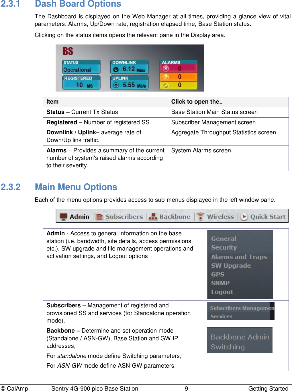
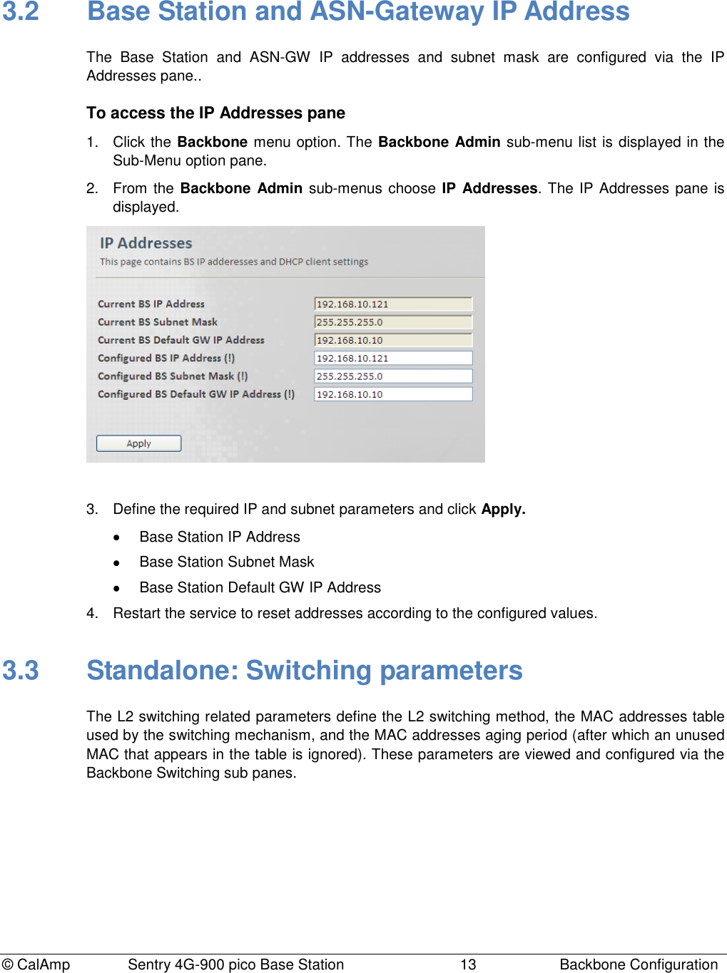
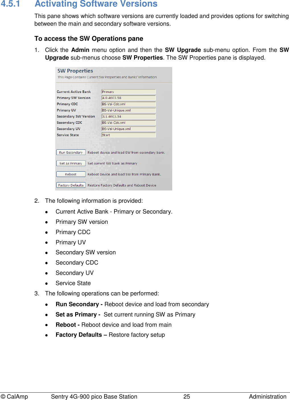
![© CalAmp Sentry 4G-900 pico Base Station 20 Administration 4.2 Base Station Identification Information This information includes the site ID, Base Station location and antenna details. To define Base Station identification information 1. Click the Admin menu option, the General sub-menu option and then choose Installation Specific. The Installation Specifics 2. Define the Site ID as defined by the Network Operator and click Apply. Several Base Station may have the same site ID. Values: [0,1000000] 3. Enter more descriptions on the location of the Base Station: Choose Installation Description (from the Admin menu, General sub-menus). The Installation Description pane appears. Define the fields and click Apply: o Address of Base Station (up to 30 characters) o Antenna type: Omni, Directional or Unknown o Antenna Azimuth in degrees, as configured by the installer: 0 to 359 o Inclination: Vertical inclination of antenna in degrees, as configured by the installer. Values: [-90,90] o Contact details: name, telephone ,etc. of service person that can be contacted.](https://usermanual.wiki/CalAmp-Wireless-Networks/1409290100.operating-manual/User-Guide-1278539-Page-24.png)
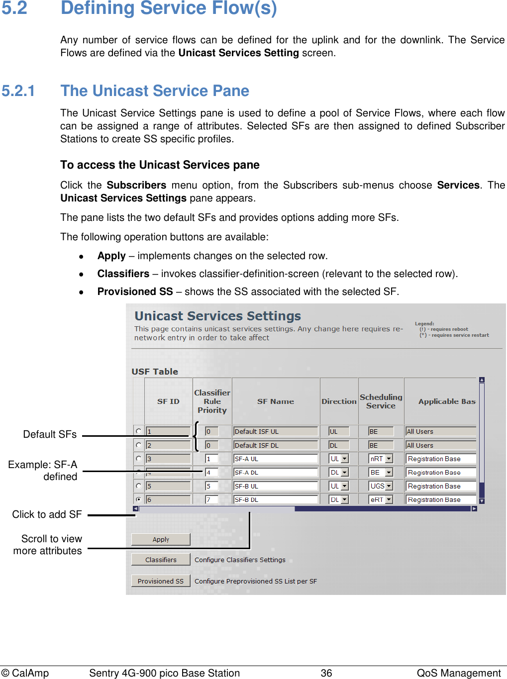
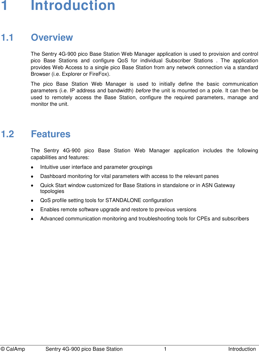
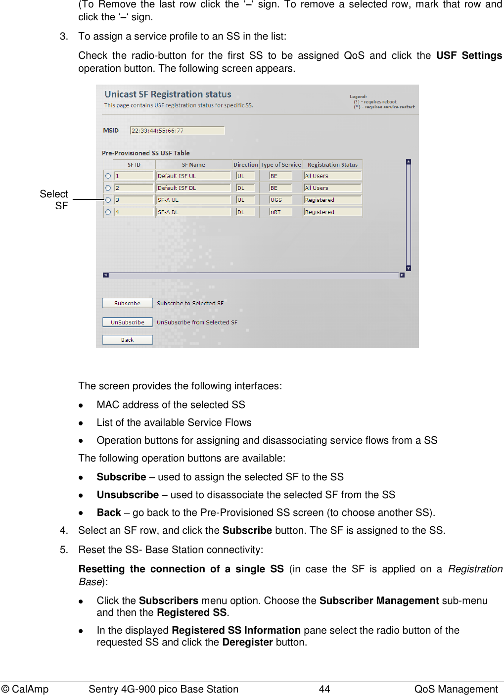
![© CalAmp Sentry 4G-900 pico Base Station 38 QoS Management Field Description SF ID Read only. Service Flow ID automatically provided by the system after applying the changes. Classification Rule Priority Classification rule priority: 0 to 255 The Priority Level determining how the SF data will be classified. The same priority can be assigned to an UL and to a DL SF. The Classification Rule Priority must be unique for each SF UL or SF DL. This parameter is related to the selected classifer. SF Name User assigned unique name identifying the Service Flow. The name should include the SF direction (UL or DL). Direction Direction to which SF is assigned - Downlink or Uplink Scheduling Service Service Scheduling Flows supported by WiMAX. Service Flow Designation Defining QoS Parameters Application Examples UGS - Unsolicited Grant Services Maximum sustained rate Maximum latency tolerance Jitter tolerance Voice over IP (VoIP) without silence suppression RT – Real-Time Polling service Minimum reserved rate Maximum sustained rate Maximum latency tolerance Traffic priority Streaming audio and video, MPEG (Motion Picture Experts Group) encoded nRT – Non-Real-Time Polling service Minimum reserved rate Maximum sustained rate Traffic priority File Transfer Protocol (FTP) BE – Best-effort service Maximum sustained rate Traffic priority Web browsing, data transfer eRT – Extended-Real-Time Polling service Minimum reserved rate Maximum sustained rate Maximum latency tolerance Jitter tolerance Traffic priority VoIP with silence suppression Applicable Base Determines the group of subscribers to which the SF will be assigned. Registration Base - assigns the SF to the explicitly configured (registered) SS. All Users - this SF will be applied to all subscribed SSs. Select this option to set this as the default profile. Min Rate [Kbits/sec] Minimum bandwidth rate for this SF.](https://usermanual.wiki/CalAmp-Wireless-Networks/1409290100.operating-manual/User-Guide-1278539-Page-42.png)
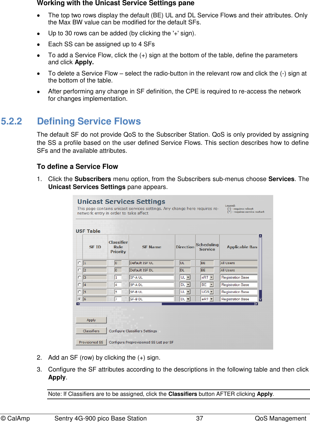
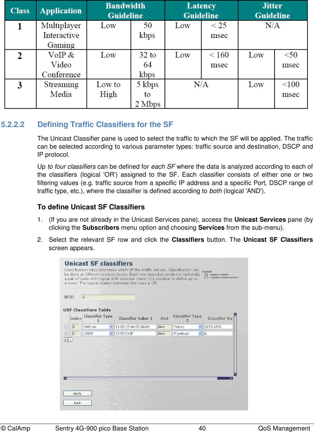
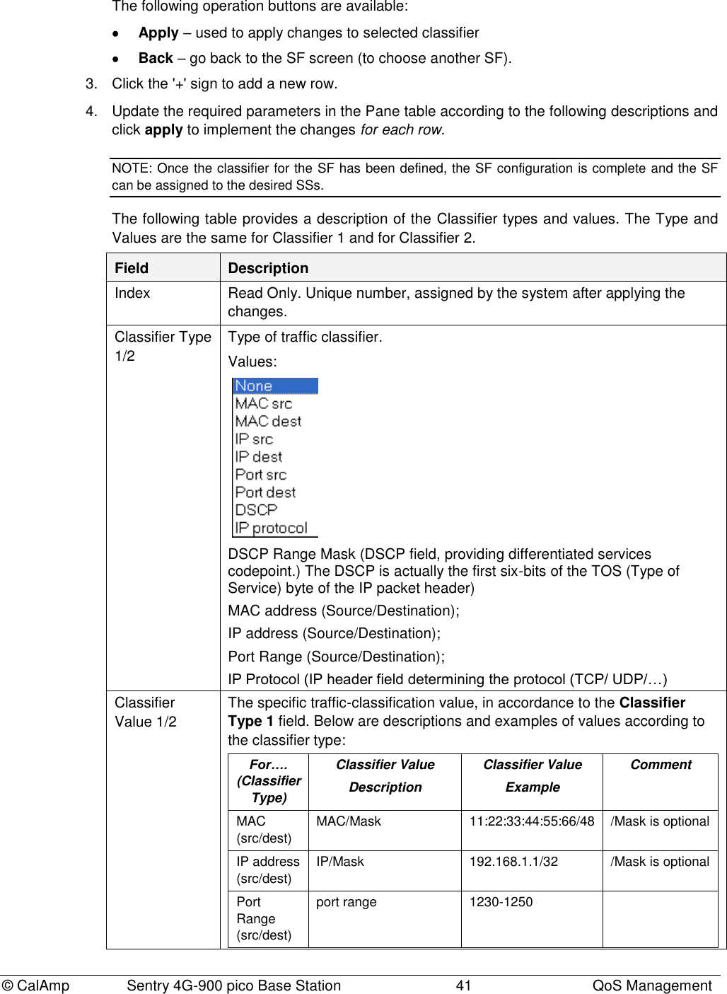
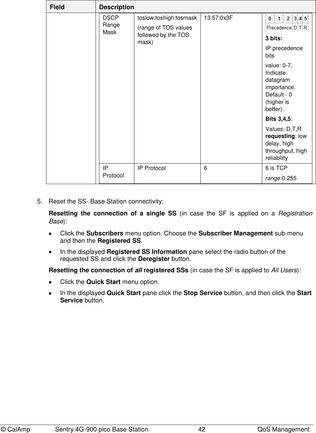
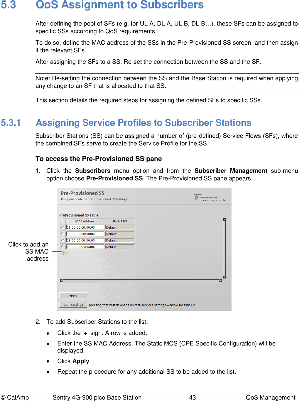
![© CalAmp Sentry 4G-900 pico Base Station 39 QoS Management Max Rate [Kbits/sec] Maximum rate for this SF. A value of „0‟ provides unlimited rate. Max Latency [µsec] (UGS, RT, eRT) Relevant only for UGS, RT and eRT. A value of „0‟ does not put a limit on latency. Maximum Latency (delay) for this SF. Set value according to the type of service (i.e. <100ms for Voice and Video applications. Unsolicited Grant [µsec] Interval (UGS, eRT) Relevant if the UGS – UGI - TBD A value of „0‟ provides unlimited UGI. Tolerated Jitter (UGS only) [µsec] the UGS tolerated jitter parameter…. A value of „0‟ does not put a limit on jitter. Unsolicited Polling Interval (RT, nRT) [µsec] The maximal nominal interval between successive polling grants opportunities for this Service Flow, especially used for silence period of VoIP traffic with silence suppression. Has Classifiers Read only. Displays whether or not this SF is assigned Traffic Classifiers. Values: [True, False] To configure the SF Classifiers see 5.2.2.2. 4. If required, define the Traffic classifiers according to the following section. 5. Reset the SS-Base Station connectivity: Resetting the connection of a single SS (in case the SF is applied on a Registration Base): Click the Subscribers menu option. Choose the Subscriber Management sub-menu and then the Registered SS. In the displayed Registered SS Information pane select the radio button of the requested SS and click the Deregister button. Resetting the connection of all registered SSs (in case the SF is applied to All Users): Click the Quick Start menu option. In the displayed Quick Start pane click the Stop Service button, and then click the Start Service button. 5.2.2.1 Bandwidth Latency and Jitter Guidelines](https://usermanual.wiki/CalAmp-Wireless-Networks/1409290100.operating-manual/User-Guide-1278539-Page-43.png)
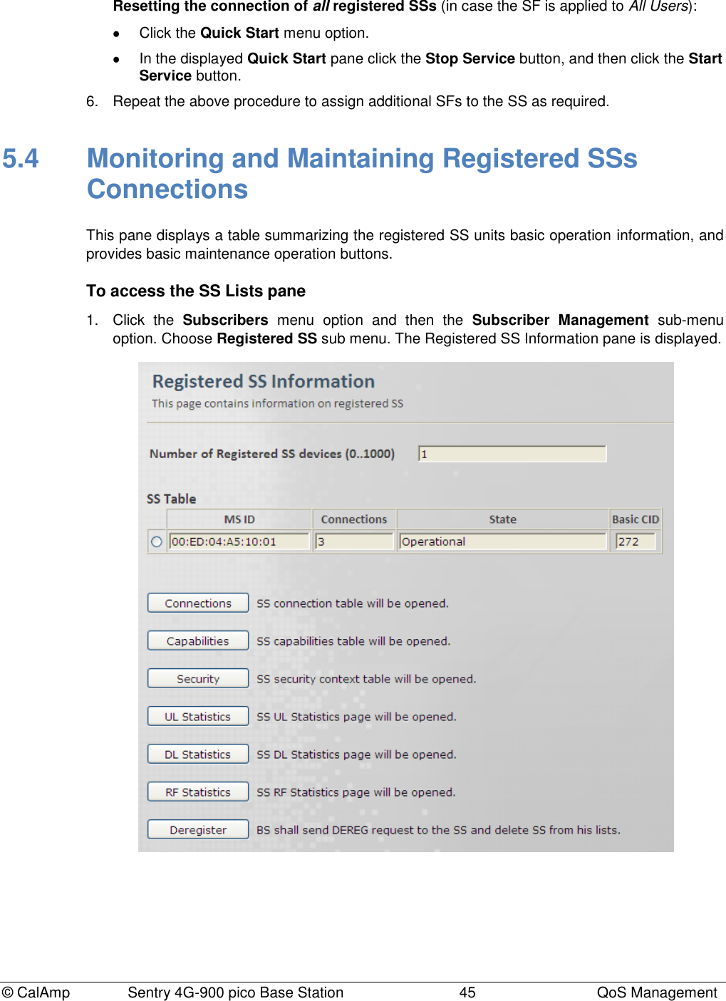
![© CalAmp Sentry 4G-900 pico Base Station 46 QoS Management 2. The following information is available: Field Description Number of Registered SS devices Range [0,1000] SS Table The displayed table provides the following information for each SS: Field Description MS ID MAC Address of SS Connections Number of DL & UL connections, associated with that MSID State SS Operation state. Values: init, DL Synchronization, Handover DL acquisition, UL Acquisition, Ranging, Handover ranging, Capabilities negotiation, Authorization, Registration, DHCP, TOD, TFTP, Operational, Sleep, IDLE, Aborted Basic CID 3. Use the available buttons to perform additional operations: Connections - SS connection hidden subtab table will be opened Capabilities – SS Capabilities hidden subtab will be opened Security – SS Security context hidden subtab will be opened UL Statistics – Provides UL Statistics DL Statistics - Provides DL Statistics RF Statistics - Provides RF Statistics Deregister – Reset the connection between the Base Station and the selected SS (Base Station shall send DEREG request to the SS and delete the SS from the lists).](https://usermanual.wiki/CalAmp-Wireless-Networks/1409290100.operating-manual/User-Guide-1278539-Page-50.png)
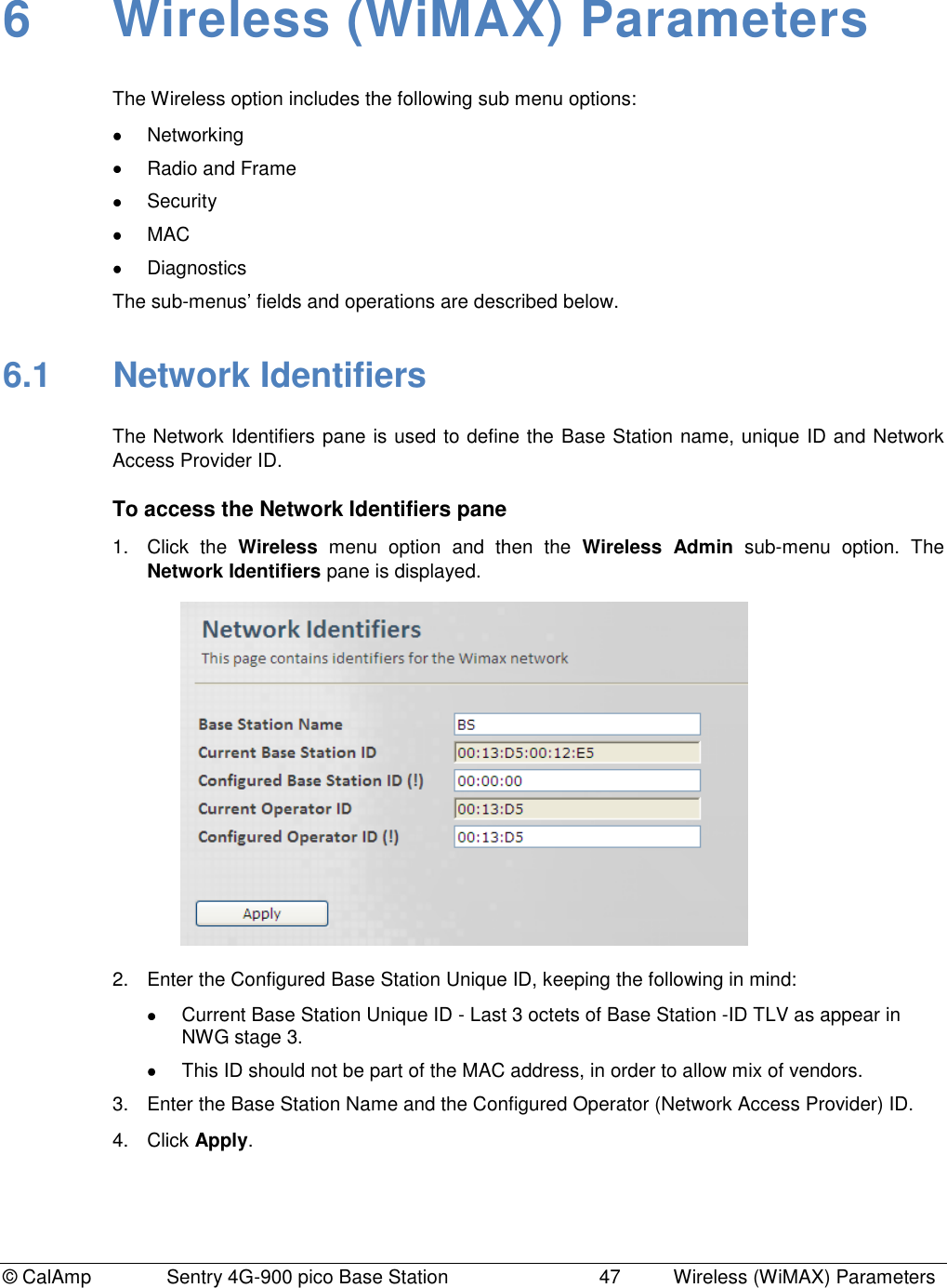
![© CalAmp Sentry 4G-900 pico Base Station 48 Wireless (WiMAX) Parameters 6.2 Radio and Frame Radio and Frame configurations and capabilities. Radio configurable parameters should be set within the valid range of values. This range is determined by the specific country regulations, and in accordance to the device capabilities. 6.2.1 Radio Capabilities read Only This pane displays the Device HW Radio configurations and capabilities. To access the Radio Capabilities pane 1. Click the Wireless menu option and then the Radio and Frame sub-menu option. From the Radio and Frame sub-menus choose Radio Capabilities. The Radio Capabilities pane is displayed. 2. The Pane displays information as follows: Field Description Min / Max Supported Frequency [KHz] Min / Max supported frequency range. Values: Min to Max, Separated by a comma. Example: 1350,1450 Supported BW [KHz] Supported bandwidths in KHz. Values are separated by commas. Example: 5000,7000,10000 Supported MIMO Schemes Supported MIMO schemes. Values: Matrixes separated with comma: A,B](https://usermanual.wiki/CalAmp-Wireless-Networks/1409290100.operating-manual/User-Guide-1278539-Page-52.png)
![© CalAmp Sentry 4G-900 pico Base Station 49 Wireless (WiMAX) Parameters Field Description Min / Max support Transmit Power [dBm] Min / Max support Transmit Power [dbm]. Values: Min and Max separated by comma. Example: 10,36 Number of RF Channels[2x2] Number of RF TX Channels 6.2.2 Radio Settings This pane provides Radio parameters settings. To access the Radio Settings pane 1. Click the Wireless menu option and then the Radio and Frame sub-menu option. From the Radio and Frame sub-menus choose Radio. The Radio Settings pane is displayed.](https://usermanual.wiki/CalAmp-Wireless-Networks/1409290100.operating-manual/User-Guide-1278539-Page-53.png)
![© CalAmp Sentry 4G-900 pico Base Station 50 Wireless (WiMAX) Parameters 2. Update the required parameters in the Pane according to the following descriptions and click Apply. Field Description Frequency [KHz] Current / Configured Frequency. This value will be in use after the next reboot or configuration flashing. Values: must be within the range of allowed frequencies (i.e. between the Min Supported Frequency and Max Supported Frequency fields – see below) Min / Max Supported Frequency [KHz] Min / Max frequency supported by the Base Station (read-only). Values: Min to Max separated by a comma. Example: 1350,1450 Tx power [dBm] Tx Transmit Power Setting. Configured Tx power should be in the valid range, as determined by the regulations and the device capabilities (i.e. Min Supported Transmit Power and Max Supported Transmit Power fields, see below). Min / Max support Transmit Power [dBm] Min / Max supported transmission power by the Base Station (read-only). Values: Min and Max separated by a comma. Example: 10,36 Initial Ranging Power [dBm] Maximum Initial Ranging Power. (Look for WiMAX def). If received power exceeds the maximum Initial ranging power, signal will not be accepted. Limits signal levels of third party equipment – used to minimize possible interference. Values: [-90,111] RF Channel RF Unit Name or ID. Values: [0,1] Active This Parameter sets\shows the Transmission Activation Status of the Base Station . Values: False - disabled True - enabled Tx Power RF unit Transmit Power (Tx) [dBm]. Values: [-50,100] Analog RSSI Analog RSSI level [dBm]. Temperature RF2 Temperature [Celsius]. Antenna Antenna Connectivity Status. Values: [Connected, Disconnected]](https://usermanual.wiki/CalAmp-Wireless-Networks/1409290100.operating-manual/User-Guide-1278539-Page-54.png)
![© CalAmp Sentry 4G-900 pico Base Station 51 Wireless (WiMAX) Parameters 6.2.3 Frame This pane provides Frame parameters settings. To access the Frame pane 1. Click the Wireless menu option and then the Radio and Frame sub-menu option. From the Radio and Frame sub-menus choose Frame. The Frame Settings pane is displayed. 2. Update the required parameters in the Pane according to the following descriptions and click Apply. Field Description Bandwidth [MHz] Configured Bandwidth. This value will be in use in the next service. Configured BW must be one of the supported BWs. Values: Default: 10 Preamble Index Configured Frame Preamble Index: Preamble Index allows the SS to perform frequency and time synchronization. The value should be different for neighboring Base Station.](https://usermanual.wiki/CalAmp-Wireless-Networks/1409290100.operating-manual/User-Guide-1278539-Page-55.png)
![© CalAmp Sentry 4G-900 pico Base Station 52 Wireless (WiMAX) Parameters Field Description Values: [0,113] Default: 0 TDD Split [%] Current / Configured DL frame resources [%]: Ratio (in percentage) between DL and UL. Values: [53,75] Default: 66 DL Major Groups Bitmap (0..63) Each bit 1-6 represents one Major or Minor group of DL resources (1-6 correspondingly). Note at least one major group shall be selected. Values: [0,63] Default: 63 UL Subchannels Bitmap UL Sub-channels Bitmap DCD Count Downlink Channel Descriptor Count. UCD Count Uplink Channel Descriptor Count.](https://usermanual.wiki/CalAmp-Wireless-Networks/1409290100.operating-manual/User-Guide-1278539-Page-56.png)
![© CalAmp Sentry 4G-900 pico Base Station 53 Wireless (WiMAX) Parameters 6.2.4 ARQ and HARQ This pane provides HARQ and ARQ parameters settings for UL and DL. To access the ARQ and HARQ pane 1. Click the Wireless menu option and then the Radio and Frame sub-menu option. From the Radio and Frame sub-menus choose ARQ and HARQ. The ARQ and HARQ Settings pane is displayed. 2. Update the required parameters in the Pane according to the following descriptions and click Apply. Field Description Type of Service This parameter defines ARQ and HARQ per type of service when operating in local mode. Default: BE, nRT, RT, eRT, UGS ARQ Activation Status This parameter specifies the activation status of ARQ for local mode per type of service. Values: [False, True] Default: False, False, False, False, False HARQ Activation Status This parameter specifies the activation status of HARQ for local mode per type of service. Values: [False, True] Default: True, True, False, False, False](https://usermanual.wiki/CalAmp-Wireless-Networks/1409290100.operating-manual/User-Guide-1278539-Page-57.png)
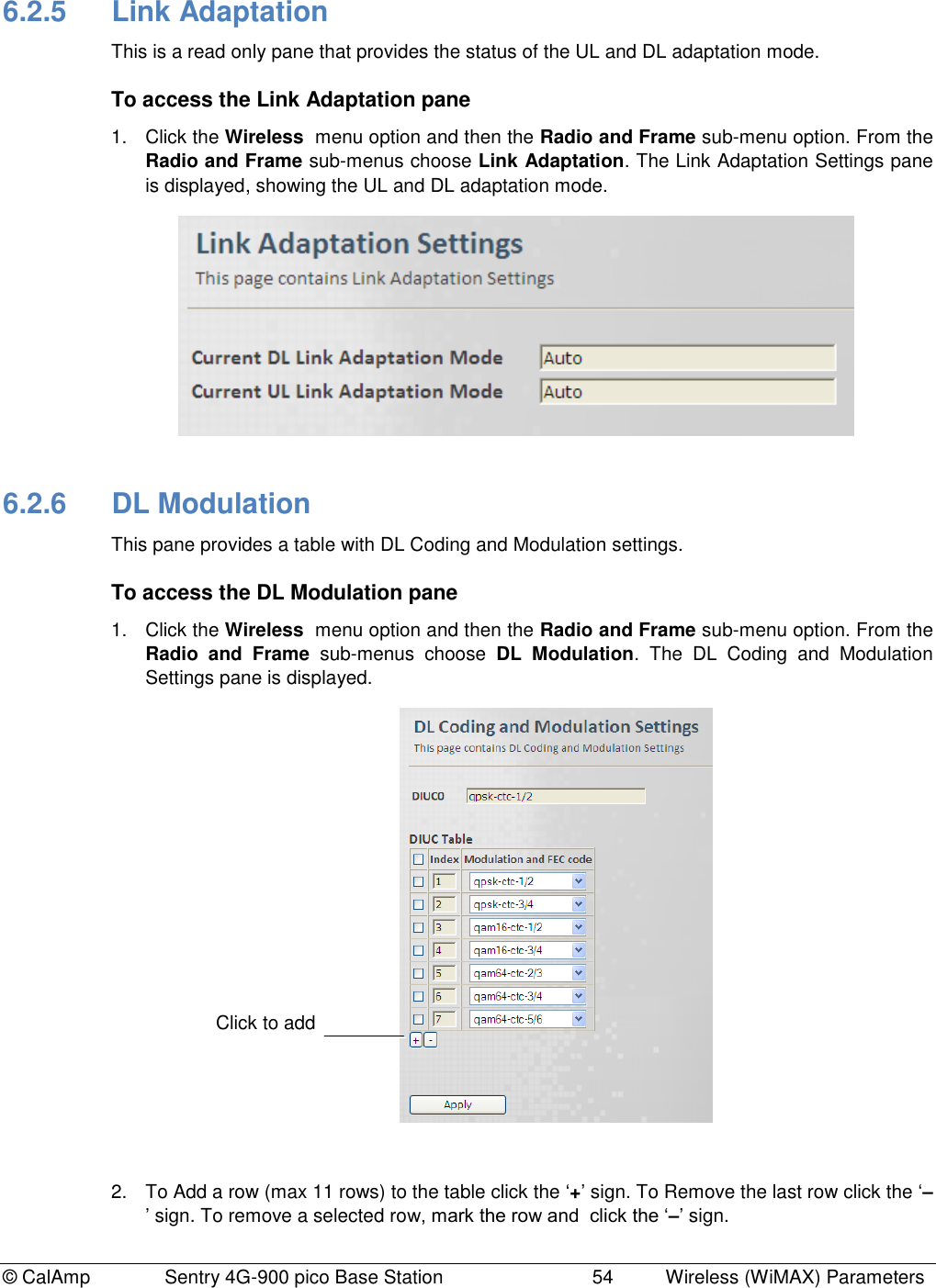
![© CalAmp Sentry 4G-900 pico Base Station 55 Wireless (WiMAX) Parameters 3. Update the required parameters in the Pane table according to the following descriptions and click Apply. Field Description Index DIUC Index Table Index is for: 0 - IUC 0 1 - IUC 1 2 - IUC 2 : 12- IUC 12 Values: [0,11] Default: 0 Modulation and FEC code Values: 6.2.7 UL Modulation This pane provides a table with UL Coding and Modulation settings. To access the UL Modulation pane 1. Click the Wireless menu option and then the Radio and Frame sub-menu option. From the Radio and Frame sub-menus choose UL Modulation. The UL Coding and Modulation Settings pane is displayed. 2. To Add a row (max 11 rows) to the table click the „+‟ sign. To Remove the last row click the „–‟ sign. To remove a selected row, mark the row and click the „–‟ sign. Click to add](https://usermanual.wiki/CalAmp-Wireless-Networks/1409290100.operating-manual/User-Guide-1278539-Page-59.png)
![© CalAmp Sentry 4G-900 pico Base Station 56 Wireless (WiMAX) Parameters 3. Update the required parameters in the Pane table according to the following descriptions and click Apply. Field Description Index UIUC Index Table Index is: 0- IUC 0 (FFB) 1- IUC 1 2- IUC 2 : 10- IUC 10 Values: [0,11] Default: 0 Modulation and FEC code Values: 6.2.8 DL Zones This pane provides DL Zone settings. To access the DL Zones pane 1. Click the Wireless menu option and then the Radio and Frame sub-menu option. From the Radio and Frame sub-menus choose DL Zones. The DL Zone Settings pane is displayed. 2. To Add a row to the table click the ‘+’ sign. To Remove the last row click the ‘–’ sign. To remove a selected row, mark the row and click the ‘–’ sign. 3. Update the required parameters in the Pane table according to the following descriptions and click Apply. Click to add](https://usermanual.wiki/CalAmp-Wireless-Networks/1409290100.operating-manual/User-Guide-1278539-Page-60.png)
![© CalAmp Sentry 4G-900 pico Base Station 57 Wireless (WiMAX) Parameters Field Description Mandatory Zone Minimal Duration in [slots] Minimal Zone Duration in [slots]. Must not exceeds DL/UL ratio. Values: [4,100] Default: 4 Mandatory Zone Maximal Duration in [slots] Maximal Zone Duration in [slots] Must be greater or equal to: Min-Number-Of-Slots-In-Time-Axis Values: [4,100] Default: 4 Mandatory Zone Permutation Type Permutation Type: a label showing the permutation type of Zone 0. Values: Default: PUSC Zone ID Zone ID Values: [0,10] Default: 1 Min slots Minimal duration in slots. Must not exceeds DL/UL ratio. Values: [0,100] Default: 0 Max slots Maximal duration in slots. Must be greater or equal to of that zone: Min-Number-Of-Slots-In-Time-Axis. Values: [0,100] Default: 100 Permutation Permutation Type (Base) Values: 0 - PUSC 1 - FUSC 2 – AMC Default: PUSC MIMO Config MIMO Configuration Values: Default: MIMO A](https://usermanual.wiki/CalAmp-Wireless-Networks/1409290100.operating-manual/User-Guide-1278539-Page-61.png)
![© CalAmp Sentry 4G-900 pico Base Station 58 Wireless (WiMAX) Parameters Field Description PRBS ID Pseudo random bit sequence (PRBS). Determines carrier and pilot position. Values: [0,2] Default: 0 Perm Base The permutation base (PermBase) is used together with the WiMAX physical layer profile to compute the subcarrier-to-sub-channel map used by a given cell. Values: [0,31] Default: 0 Use all Sub Channels Use All Sub Channels (Disable sub channels rotation). Values: True/False Default: False 6.2.9 Feedback Channel This pane provides CQICH setting options. To access the Feedback Channel (CQICH) pane Click the Wireless menu option and then the Radio and Frame sub-menu option. From the Radio and Frame sub-menus choose Feedback Channel. The Feedback Channel Settings pane is displayed. The pane displays the current feedback type.](https://usermanual.wiki/CalAmp-Wireless-Networks/1409290100.operating-manual/User-Guide-1278539-Page-62.png)
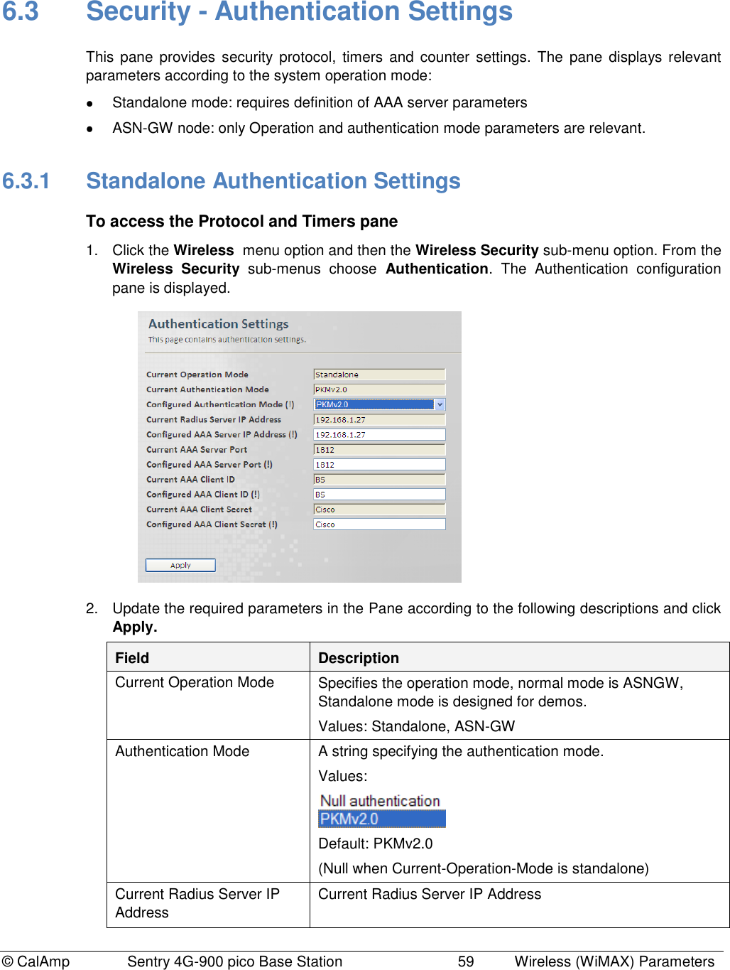
![© CalAmp Sentry 4G-900 pico Base Station 60 Wireless (WiMAX) Parameters Configured AAA Server IP Address AAA Server IP Address, Server Port, Client ID and Client Secret (AAA User Defined password AAA Server Port, Client ID, Client Secret AAA Parameters TEK Lifetime Traffic Encryption Key Lifetime in [sec]. Values: [1800,604800] Default: 43200 6.3.2 ASN-GW Authentication Settings To access the Protocol and Timers pane 1. Click the Wireless menu option and then the Wireless Security sub-menu option. From the Wireless Security sub-menus choose Authentication. The Authentication configuration pane is displayed. 2. Update the required parameters in the Pane according to the following descriptions and click Apply. Field Description Current Operation Mode Specifies the operation mode, normal mode is ASNGW, Standalone mode is designed for demos. Values: Standalone, ASN-GW Authentication Mode A string specifying the authentication mode. Values: Default: PKMv2.0 (Null when Current-Operation-Mode is standalone)](https://usermanual.wiki/CalAmp-Wireless-Networks/1409290100.operating-manual/User-Guide-1278539-Page-64.png)
![© CalAmp Sentry 4G-900 pico Base Station 61 Wireless (WiMAX) Parameters 6.4 MAC The MAC configurations menus are displayed according to the Base Station operation mode: Standalone mode – A single pane is available, providing the UCD/DCD time interval and the UCD/DCD number of notifications. ASN-GW mode – three panes are available, describing the MAC settings, Neighbor Base Stations and DCD triggers. The following sections describe the ASN-GW mode MAC screens. 6.4.1 General Info – MAC Settings This pane provides general MAC settings such as MAC messages time intervals, formats, etc. To access the General Info – MAC Settings pane 1. Click the Wireless menu option and then the MAC sub-menu option. From the MAC sub-menus choose General Info. The General Info MAC Settings pane is displayed. 2. Update the required parameters in the Pane according to the following descriptions and click Apply. Field Description UCD Period Defines the time interval (in [ms]), after which the UCD appears (e.g. every 100 ms). Values: [5,20000] Default: 1000 DCD Period Defines the time interval(in [ms]) after which the DCD appears (e.g. every 100 ms). Values: [5,20000] Default: 1000](https://usermanual.wiki/CalAmp-Wireless-Networks/1409290100.operating-manual/User-Guide-1278539-Page-65.png)
![© CalAmp Sentry 4G-900 pico Base Station 62 Wireless (WiMAX) Parameters Field Description UCD Repeat Number of UCD message notifications before new message appears. Values: [1,5] Default: 3 DCD Repeat Number of DCD message notifications before new message appears. Values: [1,5] Default: 3 NBR advertise Period Period in frames to advertise neighboring Base Station. Values: [1000,100000] Default: 1000 NBR Advertisement Activation Mode Enable/Disable Base Station advertisement of NSP in NBR TLV message broadcasting. Values: False - disable, True – enable Default: True 6.4.2 Neighbor Base Station This pane provides a table of the Neighbor Base Station‟s details – used for handover. To access the Neighbor Base Station Settings pane 1. Click the Wireless menu option and then the MAC sub-menu option. From the MAC sub-menus choose Neighbor Base Station. The Neighbor Base Station Settings pane is displayed. Click to add](https://usermanual.wiki/CalAmp-Wireless-Networks/1409290100.operating-manual/User-Guide-1278539-Page-66.png)
![© CalAmp Sentry 4G-900 pico Base Station 63 Wireless (WiMAX) Parameters 2. To Add a row to the table click the „+‟ sign. To Remove the last row click the „–‟ sign. To remove a selected row, mark the row and click the „–‟ sign. 3. Update the required parameters in the Pane table and click Apply. The table provides neighboring Base Stations attributes. 6.4.3 DCD Triggers This pane provides a table of the DCD Trigger Settings. Timing for handover triggers. Look for neighbors in order to perform handover…… To access the DCD Triggers Settings pane 1. Click the Wireless menu option and then the MAC sub-menu option. From the MAC sub-menus choose DCD Triggers. The DCD Triggers Settings pane is displayed. 2. To Add a row to the table click the “+” sign. To Remove the last row click the “–“ sign. To remove a selected row, mark the row and click the “–“ sign. 3. Update the required parameters in the Pane table according to the following descriptions and click Apply. Field Description Number of DCD Triggers Number of configured DCD triggers Index DCD Trigger Index. Default: 0 Metric This parameter specifies the DCD metric. Values: Default: CINR Duration This parameter specifies the average interval in frames duration. Values: [1,100] Click to add](https://usermanual.wiki/CalAmp-Wireless-Networks/1409290100.operating-manual/User-Guide-1278539-Page-67.png)
![© CalAmp Sentry 4G-900 pico Base Station 64 Wireless (WiMAX) Parameters Field Description Default: 40 Value [1/4, 1/2 , 1/F dB] Trigger value is the value used in comparing measured metric. The value quota measurement depends on the trigger type (metric) as follows: For RSSI – [1/4dB] For CINR – [1/2 dB] For RTD – [1/Fs] (frequency sample) Default: 16 Function This parameter specifies the function used for the metric. Values: Default: Sbs greater abs value Action Action performed upon reaching trigger condition. Values: Default: Report](https://usermanual.wiki/CalAmp-Wireless-Networks/1409290100.operating-manual/User-Guide-1278539-Page-68.png)
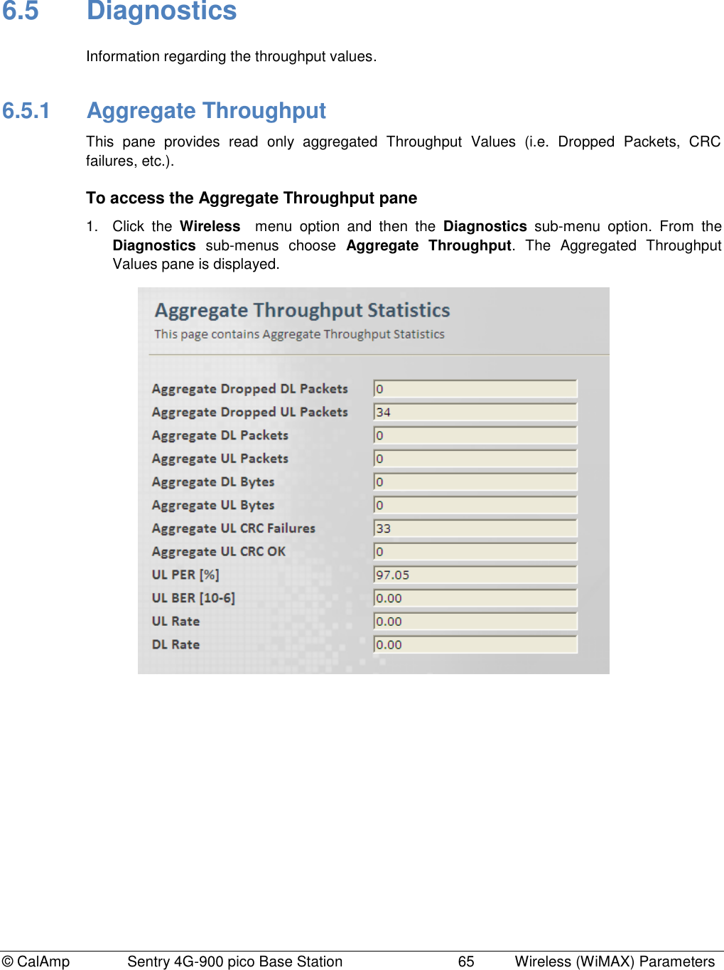
![© CalAmp Sentry 4G-900 pico Base Station 66 Wireless (WiMAX) Parameters 2. The parameters displayed in the Pane are according to the following descriptions: Field Description Aggregated Dropped DL / UL Packets Total number of aggregated Dropped DL / UL Packets since last reset. Aggregated DL / UL Packets Total number of Aggregated DL / UL Packets since last reset. Aggregated DL / UL Bytes Total number of Aggregated DL / UL Bytes since last reset. Aggregated UL CRC Failures Total number of Aggregated UL CRC Failures since last reset. Aggregated UL CRC OK Total number of Aggregated UL CRC OK since last reset. UL PER [%] UL Packet Error Rate UL BER [10-6] UL Bit Error Rate UL / DL Rate UL / DL Rate](https://usermanual.wiki/CalAmp-Wireless-Networks/1409290100.operating-manual/User-Guide-1278539-Page-70.png)