CalAmp Wireless Networks 1409290100 900 MHz Broadband Base Station User Manual operating manual
CALAMP WIRELESS NETWORKS INC. 900 MHz Broadband Base Station operating manual
Contents
- 1. antenna information
- 2. operating manual
- 3. install guide
operating manual
Sentry4G-900 pico Base Station
Operating Manual
May 2010
299 Johnson Ave, Suite 110
Waseca, MN 56093
Phone: (800) 992-7774
Fax: (507) 833-6748
www.calamp.com
Sentry 4G-900 pico Base Station Operating Manual
Copyright © 2010
ALL RIGHTS RESERVED
Dissemination or reproduction of this document, or evaluation and communication of its contents, is not authorized except where
expressly permitted. Violations are liable for damages. All rights reserved, particularly for the purposes of patent application or trademark
registration.
This document contains proprietary information, which is protected by copyright. All rights are reserved. No part of this document may be
photocopied, reproduced or translated to another language without prior written consent.
Disclaimer Of Liability
We have checked the contents of this manual against the hardware and software described. However, deviations from the description
cannot be completely ruled out.
shall not be liable for any errors or omissions contained herein or for consequential damages in connection with the furnishing,
performance, or use of this material.
The information given in this document is reviewed regularly and any necessary corrections will be included in subsequent editions. We
appreciate any suggested improvements. We reserve the right to make technical improvements without notice.
Warranty
One (1) year from date of purchase, return to factory. For warranty details, contact your customer service representative.

Table of Contents
1 Introduction .................................................................................................... 1
1.1 Overview .................................................................................................................................... 1
1.2 Features ..................................................................................................................................... 1
2 Getting Started................................................................................................ 2
2.1 Opening a Web Session to the Base Station ......................................................................... 2
2.2 Initial Setup the Base Station via Quick Start ........................................................................ 4
2.2.1 Verifying and Setting Operation Mode – ASN Gateway or Standalone ...................... 4
2.2.2 ASN-Gateway Mode Quick Start ................................................................................. 5
2.2.3 Standalone Mode Quick Start ...................................................................................... 6
2.3 Navigating the Web Manager Screen ...................................................................................... 8
2.3.1 Dash Board Options .................................................................................................... 9
2.3.2 Main Menu Options ...................................................................................................... 9
2.3.3 Modifying Parameters ................................................................................................ 10
2.4 Logout ...................................................................................................................................... 11
3 Backbone Configuration .............................................................................. 12
3.1 Setting the Operation Mode ................................................................................................... 12
3.2 Base Station and ASN-Gateway IP Address ........................................................................ 13
3.3 Standalone: Switching parameters ....................................................................................... 13
3.3.1 Switching Settings ..................................................................................................... 14
3.3.2 MAC Addresses Table ............................................................................................... 15
3.4 ASN-GW Mode: ASN Settings ................................................................................................ 16
3.4.1 ASN-GW Link Settings .............................................................................................. 16
3.4.2 Keep Alive Settings .................................................................................................... 17
4 Administration .............................................................................................. 18
4.1 Viewing Device Status and Information ................................................................................ 18
4.1.1 Main Status Pane ...................................................................................................... 18
4.1.2 Device Info ................................................................................................................. 19
4.2 Base Station Identification Information ................................................................................ 20
4.3 Security .................................................................................................................................... 21
4.3.1 Available Authentication Levels ................................................................................. 21
4.3.2 Defining Users and their Access Permissions ........................................................... 21
4.3.3 SNMP Settings and Trap Destination Addresses ...................................................... 22
4.4 Alarms and Traps .................................................................................................................... 23
4.4.1 Viewing a Summary of System Alarms ..................................................................... 23
4.4.2 Traps – SNMP Trap Settings ..................................................................................... 24
4.5 Software Versions Management ............................................................................................ 24

4.5.1 Activating Software Versions ..................................................................................... 25
4.5.2 FTP Server Configuration .......................................................................................... 26
4.5.3 Downloading Software Versions ................................................................................ 27
4.5.4 Managing Main Software Components ..................................................................... 28
4.5.5 Managing Secondary Software Version Files ............................................................ 29
4.5.6 Upgrade from Version 3.0.4602.yy ............................................................................ 30
4.6 GPS Settings ........................................................................................................................... 34
5 QoS Management ......................................................................................... 35
5.1 QoS Definition Flow ................................................................................................................ 35
5.2 Defining Service Flow(s) ........................................................................................................ 36
5.2.1 The Unicast Service Pane ......................................................................................... 36
5.2.2 Defining Service Flows .............................................................................................. 37
5.3 QoS Assignment to Subscribers ........................................................................................... 43
5.3.1 Assigning Service Profiles to Subscriber Stations ..................................................... 43
5.4 Monitoring and Maintaining Registered SSs Connections ................................................. 45
6 Wireless (WiMAX) Parameters .................................................................... 47
6.1 Network Identifiers .................................................................................................................. 47
6.2 Radio and Frame ..................................................................................................................... 48
6.2.1 Radio Capabilities read Only ..................................................................................... 48
6.2.2 Radio Settings ........................................................................................................... 49
6.2.3 Frame ......................................................................................................................... 51
6.2.4 ARQ and HARQ ......................................................................................................... 53
6.2.5 Link Adaptation .......................................................................................................... 54
6.2.6 DL Modulation ............................................................................................................ 54
6.2.7 UL Modulation ............................................................................................................ 55
6.2.8 DL Zones ................................................................................................................... 56
6.2.9 Feedback Channel ..................................................................................................... 58
6.3 Security - Authentication Settings ........................................................................................ 59
6.3.1 Standalone Authentication Settings ........................................................................... 59
6.3.2 ASN-GW Authentication Settings .............................................................................. 60
6.4 MAC .......................................................................................................................................... 61
6.4.1 General Info – MAC Settings ..................................................................................... 61
6.4.2 Neighbor Base Station ............................................................................................... 62
6.4.3 DCD Triggers ............................................................................................................. 63
6.5 Diagnostics .............................................................................................................................. 65
6.5.1 Aggregate Throughput ............................................................................................... 65
7 List of Acronyms .......................................................................................... 67

© CalAmp Sentry 4G-900 pico Base Station 1 Introduction
1 Introduction
1.1 Overview
The Sentry 4G-900 pico Base Station Web Manager application is used to provision and control
pico Base Stations and configure QoS for individual Subscriber Stations . The application
provides Web Access to a single pico Base Station from any network connection via a standard
Browser (i.e. Explorer or FireFox).
The pico Base Station Web Manager is used to initially define the basic communication
parameters (i.e. IP address and bandwidth) before the unit is mounted on a pole. It can then be
used to remotely access the Base Station, configure the required parameters, manage and
monitor the unit.
1.2 Features
The Sentry 4G-900 pico Base Station Web Manager application includes the following
capabilities and features:
Intuitive user interface and parameter groupings
Dashboard monitoring for vital parameters with access to the relevant panes
Quick Start window customized for Base Stations in standalone or in ASN Gateway
topologies
QoS profile setting tools for STANDALONE configuration
Enables remote software upgrade and restore to previous versions
Advanced communication monitoring and troubleshooting tools for CPEs and subscribers

© CalAmp Sentry 4G-900 pico Base Station 2 Getting Started
2 Getting Started
The Base Station should be provisioned with basic parameters BEFORE it is mounted (i.e. on
the pole) where physical access will be more challenging. This is easily and quickly
accomplished by opening a Web session to the Base Station and using the Web Manager Quick
Start screen.
This chapter provides the following information:
How to open a Web session to the Base Station
How to provision the unit via the Quick Start tab in two operation modes: ASN-Gateway
(default mode) and standalone mode
Navigating the Web Manager application
2.1 Opening a Web Session to the Base Station
A Web session can be opened to the Base Station using two methods: local and remote.
Local Web sessions are usually used during setup to provision the unit with the IP address
provided by the system administrator and to configure basic parameters. All the parameters
required for initial setup are concentrated in the Quick Start menu.
NOTE: Remote sessions are used during normal operation.
To open a local session
Note: The default IP address of the Base Station is 192.168.100.100
1. Verify that your computer is running Windows XP OS.
2. Use an Ethernet cross-cable to connect your computer (i.e. laptop) Ethernet port to the Base
Station Ethernet management port.
NOTE: Some laptops may not require a cross-cable to locally connect to an Ethernet port since
automatic identification of cross-cable connections are supported. For these type of computers, a
standard Ethernet may be connected locally to the Base Station.
Ethernet cross-cable
© CalAmp Sentry 4G-900 pico Base Station 3 Getting Started
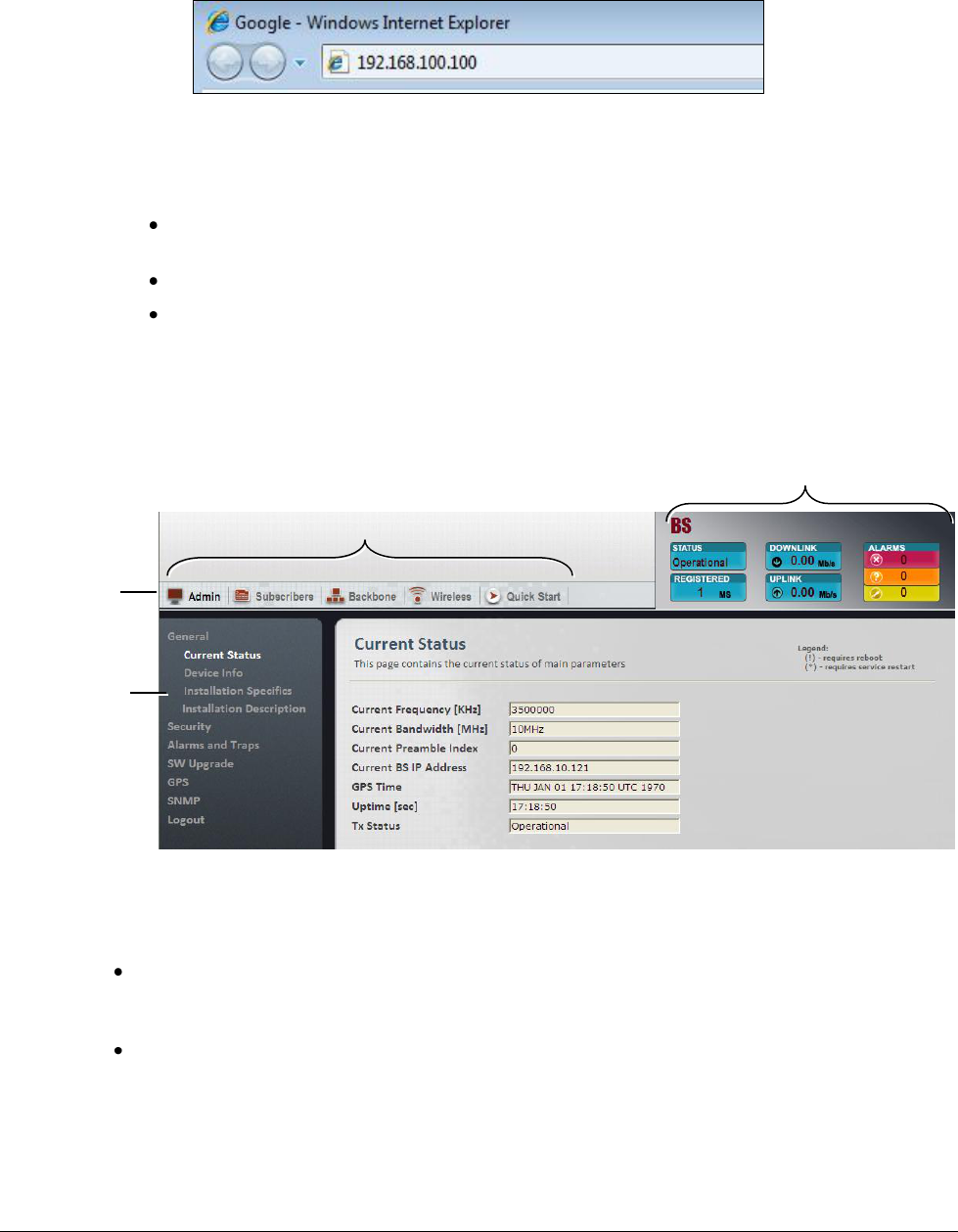
3. Launch your Web Browser (i.e. Explorer or FireFox) and enter the Base Station
default IP address in the address bar.
4. Press the Enter key. The login window appears.
5. In the Login window, enter your provided User Name and Password.
The Web Manager window appears. The window consists of:
Dashboard showing the main readings – click on a reading to access the corresponding
screen.
Main menu options – the relevant sub-menus are displayed in the left pane
The display area showing the currently selected sub-pane options.
For a detailed explanation on navigating the Web Manager, refer to section 2.3.
The Admin menu, Current Status sub-menu item is displayed by default, providing status
information on the Base Station.
What next?
To provision the unit (before physical mounting) - define the Quick Start parameters (see
2.2). Once the Quick Start parameters have been defined, you will be able to access the
Base Station remotely via an internet connection.
Learn how to navigate the Web Manager – refer to 2.3 Navigating the Web Manager Screen.
Admin menu
Sub-menus
Dash Board
Main menus
© CalAmp Sentry 4G-900 pico Base Station 4 Getting Started
2.2 Initial Setup the Base Station via Quick Start
NOTE: The Quick Start menu is usually accessed for the first time via a local connection
BEFORE the Base Station is mounted onto the pole.
The Quick Start screen concentrates the IP address and other basic parameters required to set
up the Base Station and to perform basic operations; these include Base Station service control
and reboot.
The Web Manager supports two operation modes, each with a dedicated Quick Start screen:
ASN Gateway – this is the default mode, corresponding to an installation topology that
includes an ASN Gateway. In this type of installation the QoS is configured through the
Gateway. No QoS set up is required at the Base Station.
Standalone – in this mode, the Base Station installation topology does NOT include an ASN
Gateway. It is required to configure the Web Browser to run in this mode.
The operation mode can be verified and modified through the Web Manager (Backbone menu).
This section describes how to verify and modify the Web Manager mode according to the
installation topology, and the Quick Start options for each mode.
2.2.1 Verifying and Setting Operation Mode – ASN Gateway or
Standalone
The Web Manager is by default set to operate in ASN-GW mode. Configure the Web Manager
operation mode to correspond the system topology: Standalone or ASN-GW. The selected
mode affects some of the Web Manger features and displays.
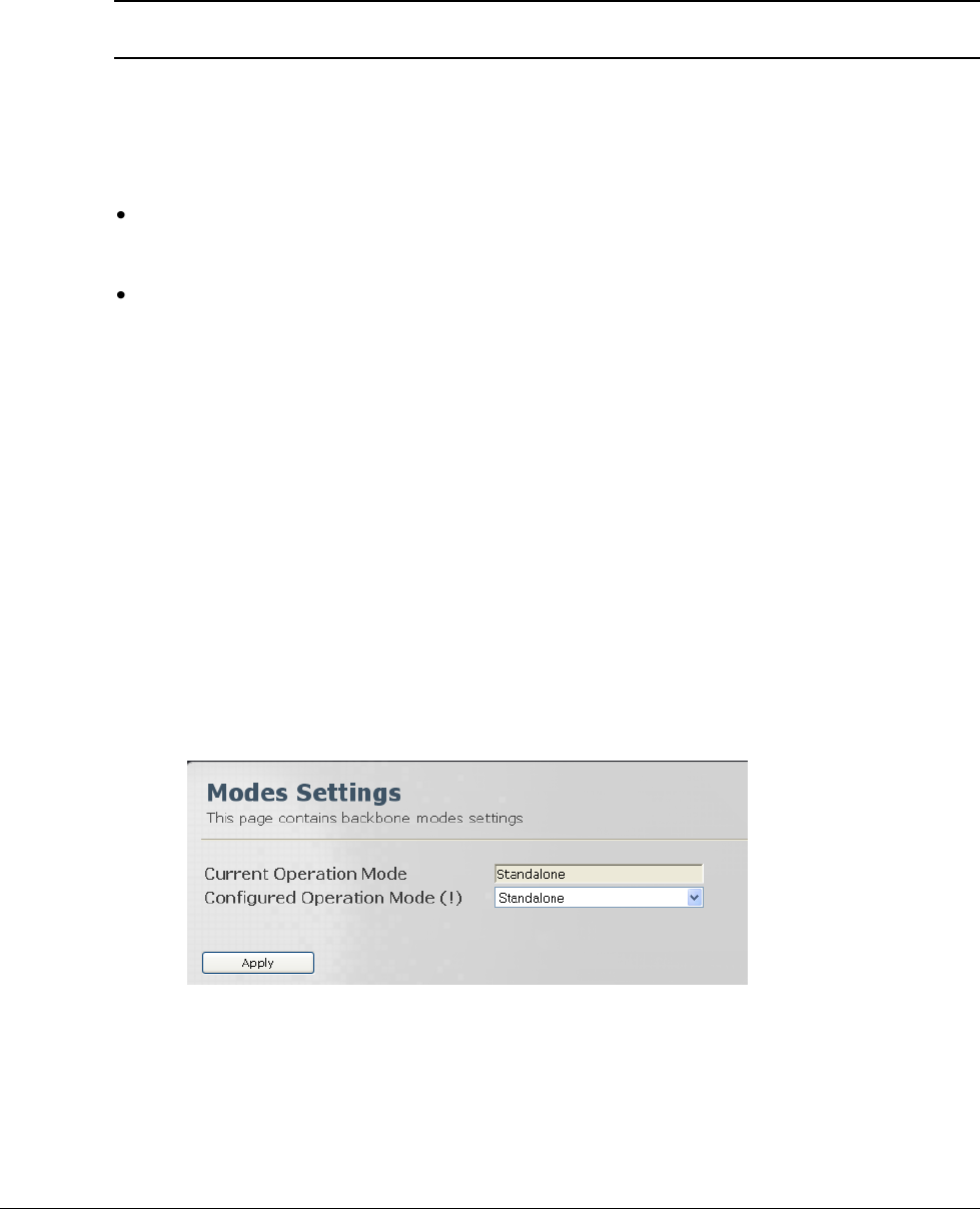
To view and configure the operation mode
1. Click the Backbone menu option. Choose the Backbone Admin sub-menu and then the
Operation Modes. The Operation Modes screen appears.
2. In the Configured Operation Mode field set the value to Standalone or ASN-GW according
to the system topology and click Apply.
© CalAmp Sentry 4G-900 pico Base Station 5 Getting Started
2.2.2 ASN-Gateway Mode Quick Start
Follow this instructions in this section if the Base Station is in an ASN Gateway topology.
NOTE: All the parameters available in this pane, are also available in other panes corresponding
to their parameter groups.
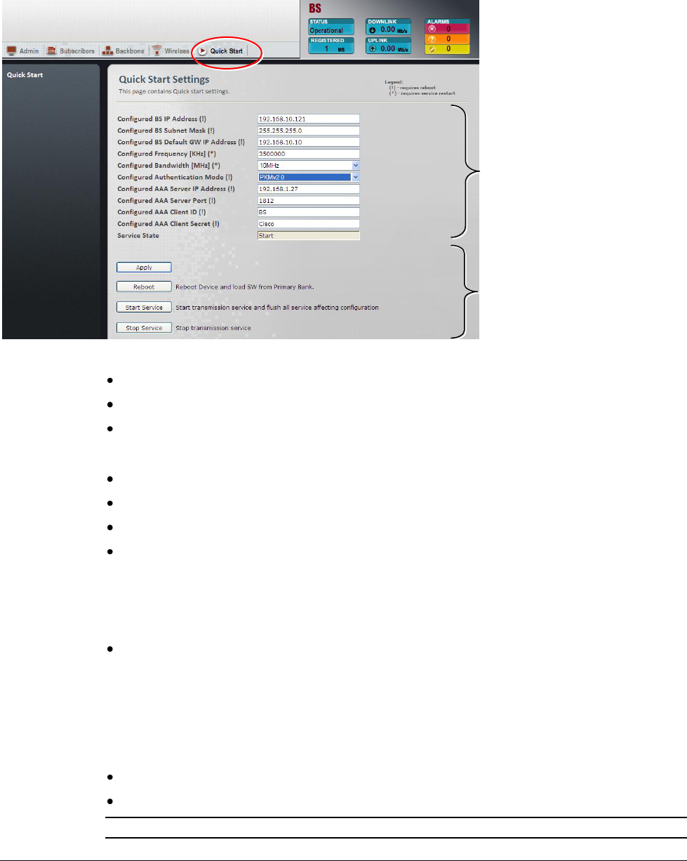
The Quick Start pane provides the basic parameters required for setting up the Base Station.
These include the unit and ASN Gateway address, frequency, bandwidth, etc.
These parameters require re-starting the service (*) or rebooting the Base Station (!) as
indicated. (See section 2.3.3). The necessary operation buttons are provided in the pane.
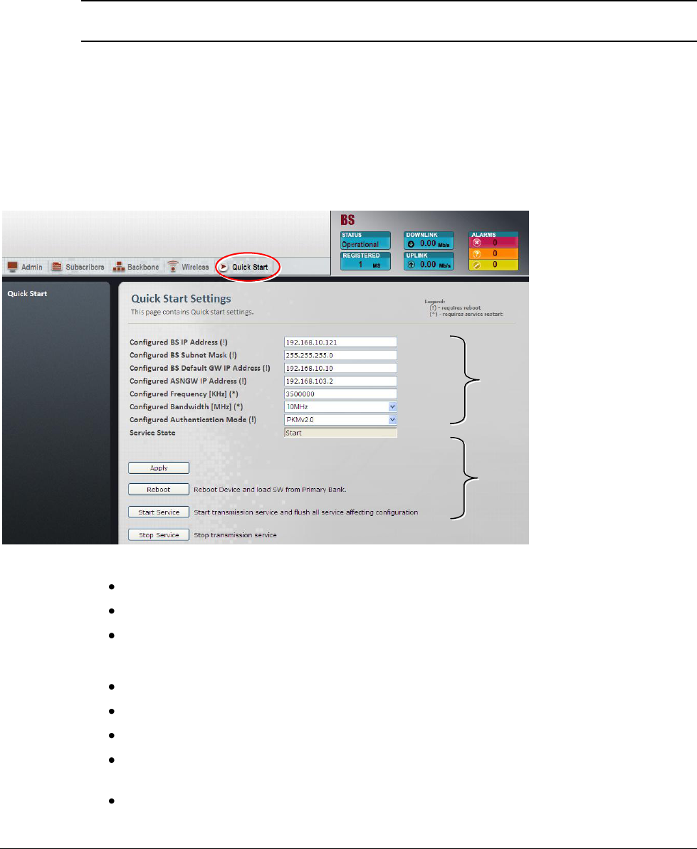
To set up the unit via the Quick Start pane
1. Click the Quick Start menu option. The Quick Start pane appears.
The following operation buttons are available:
Apply – implements changes performed by the user.
Reboot – reboot device and load SW from Preliminary bank
Stop Service / Start Service – two buttons used when service restart is required.
2. Update the required parameters in the Pane:
Base Station IP Address, Subnet Mask and Default GW (requires reboot).
ASN Gateway IP Address (requires reboot)
Base Station Center Frequency (requires service restart)
Base Station Bandwidth – Values: 3.5MHz, 5MHz, 7MHz, 10MHz. (requires service
restart)
Authentication Mode:
Basic communication
parameters
(Corresponding to mode:
Standalone/ASN-GW)
Control options

© CalAmp Sentry 4G-900 pico Base Station 6 Getting Started
o Null authentication – if this mode is selected, AAA Server parameters are not
relevant.
o PKMv2.0 – select this mode if AAA Server is used.
3. Click Apply to save the changes. The parameters will not be uploaded to the Base Station
until the appropriate Restart or Reboot operation was performed.
4. Depending on the parameters that were modified, perform the relevant operation in order to
update the changes to the Base Station:
Restart the service (*) – click Stop Service and then Start Service
Reboot the Base Station (!) - click Reboot.
NOTE: (If necessary), to restore the factory defaults, click the Factory Default button.
The GPS link state shows the status of the GPS link:
Auto – Default. Base Station waits for GPS synchronization before beginning
transmission. This is usually the normal operation mode for multi-sector systems.
Start – Base Station begins transmission without waiting for GPS synchronization. Used
for single sector systems or for testing. The Stop option is used to discontinue
transmission.
Stop – Used to discontinue transmission initiated by Start.
NOTE: By default, GPS operation is enabled. To disable GPS (i.e. for operation in the lab or
testing), refer to section 4.6.
2.2.3 Standalone Mode Quick Start
Follow this instructions in this section if the Base Station is in Standalone topology.
NOTE: All the parameters available in this pane, are also available in other panes corresponding
to their parameter groups.
The Quick Start pane provides the basic parameters required for setting up the Base Station.
These include the unit IP address parameters, frequency and bandwidth, and AAA Server
settings.
These parameters require re-starting the service (*) or rebooting the Base Station (!) as
indicated. (See section 2.3.3). The necessary operation buttons are provided in the pane.
© CalAmp Sentry 4G-900 pico Base Station 7 Getting Started
To set up the unit via the Quick Start pane
1. Click the Quick Start menu option. The Quick Start pane appears.
The following operation buttons are available:
Apply – implements changes performed by the user.
Reboot – reboot device and load SW from Preliminary bank
Stop Service / Start Service – two buttons used when service restart is required.
2. Update the required parameters in the Pane:
Base Station IP Address, Subnet Mask and Default GW (requires reboot).
Base Station Center Frequency (requires service restart)
Base Station Bandwidth – Values: 3.5MHz, 5MHz, 7MHz, 10MHz (default)
Authentication Mode:
o Null authentication – if this mode is selected, AAA Server parameters are not
relevant.
o PKMv2.0 – if this mode is selected, configure the AAA Server parameters
AAA Server IP Address, Server Port, Client ID and Client Secret (AAA User Defined
password)
3. Click Apply to save the changes. The parameters will not be uploaded to the Base Station
until the appropriate Restart or Reboot operation was performed.
4. Depending on the parameters that were modified, perform the relevant operation in order to
update the changes to the Base Station:
Restart the service (*) – click Stop Service and then Start Service
Reboot the Base Station (!) - click Reboot.
NOTE: (If necessary), to restore the factory defaults, click the Factory Default button.
Basic communication
parameters
(Corresponding to mode:
Standalone/ASN-GW)
Control options
© CalAmp Sentry 4G-900 pico Base Station 8 Getting Started
The GPS link state shows the status of the GPS link:
NOTE: By default, GPS operation is enabled. To disable GPS (i.e. for operation in the lab or
testing), refer to section 4.6.
Auto – Default. Base Station waits for GPS synchronization before beginning
transmission. This is usually the normal operation mode for multi-sector systems.
Start – Base Station begins transmission without waiting for GPS synchronization. Used
for single sector systems or for testing. The Stop option is used to discontinue
transmission.
Stop – Used to discontinue transmission initiated by Start.
2.3 Navigating the Web Manager Screen
The Base Station management tool screens consist of four main areas:
Dash Board – Provides Base Station main status indications: Alarms, Up/Down rate,
registration elapsed time, Base Station status. Clicking on the status items opens the
relevant pane in the Display area.
Main Menu Options – a set of menus, where clicking each menu displays the corresponding
set of sub-menus in the Sub-Menu Options Pane.
Sub-Menu Options Pane – a set of commands and sub-menus related to the selected
menu option. Selecting a sub-menu item, displays the relevant options in the Work Area.
Display Area – display corresponds to the selected sub-menu item.
Sub-Menu
Options Pane
Main Menu Options
Dash Board
Display area
Operation
button
© CalAmp Sentry 4G-900 pico Base Station 9 Getting Started
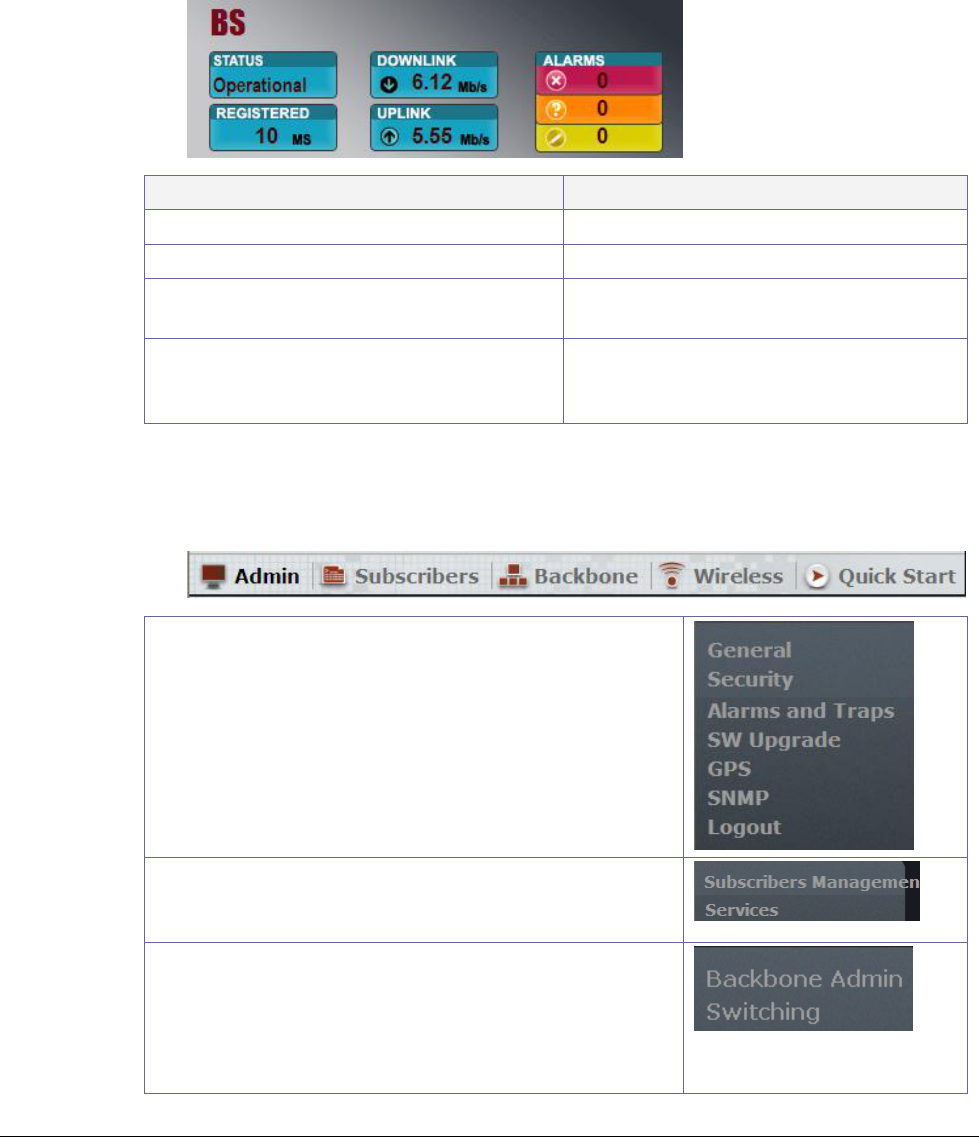
2.3.1 Dash Board Options
The Dashboard is displayed on the Web Manager at all times, providing a glance view of vital
parameters: Alarms, Up/Down rate, registration elapsed time, Base Station status.
Clicking on the status items opens the relevant pane in the Display area.
Item
Click to open the..
Status – Current Tx Status
Base Station Main Status screen
Registered – Number of registered SS.
Subscriber Management screen
Downlink / Uplink– average rate of
Down/Up link traffic.
Aggregate Throughput Statistics screen
Alarms – Provides a summary of the current
number of system's raised alarms according
to their severity.
System Alarms screen
2.3.2 Main Menu Options
Each of the menu options provides access to sub-menus displayed in the left window pane.
Admin - Access to general information on the base
station (i.e. bandwidth, site details, access permissions
etc.), SW upgrade and file management operations and
activation settings, and Logout options
Subscribers – Management of registered and
provisioned SS and services (for Standalone operation
mode).
Backbone – Determine and set operation mode
(Standalone / ASN-GW), Base Station and GW IP
addresses;
For standalone mode define Switching parameters;
For ASN-GW mode define ASN-GW parameters.
© CalAmp Sentry 4G-900 pico Base Station 10 Getting Started
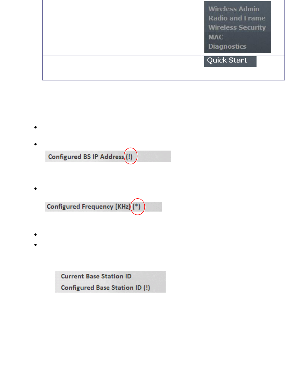
Wireless – Access to all WiMAX parameters configuration
and diagnostics options.
Quick Start – Access to all parameters required for initial
set up of the system, depending on the operation mode
(Standalone / ASN-GW).
2.3.3 Modifying Parameters
Modified parameters are updated on the Base Station under three conditions, depending on the
parameter:
Some parameters do not require special operations - simply click Apply and they are
updated on the Base Station.
Some parameters affect the service – these are marked by an exclamation mark (!).
To update these parameters, click Stop Service and then Start Service (in the Quick Start
panel).
Some parameters are updated after performing system reboot - these are marked by an
asterisk (*).
For parameters that require reboot or service restart, two values are displayed:
The current value used by the Base Station.
The configured value - typed by the user but not yet updated onto the Base Station. (Will
be updated in the Base Station after the required restart/reboot operation).
See example below.
© CalAmp Sentry 4G-900 pico Base Station 11 Getting Started
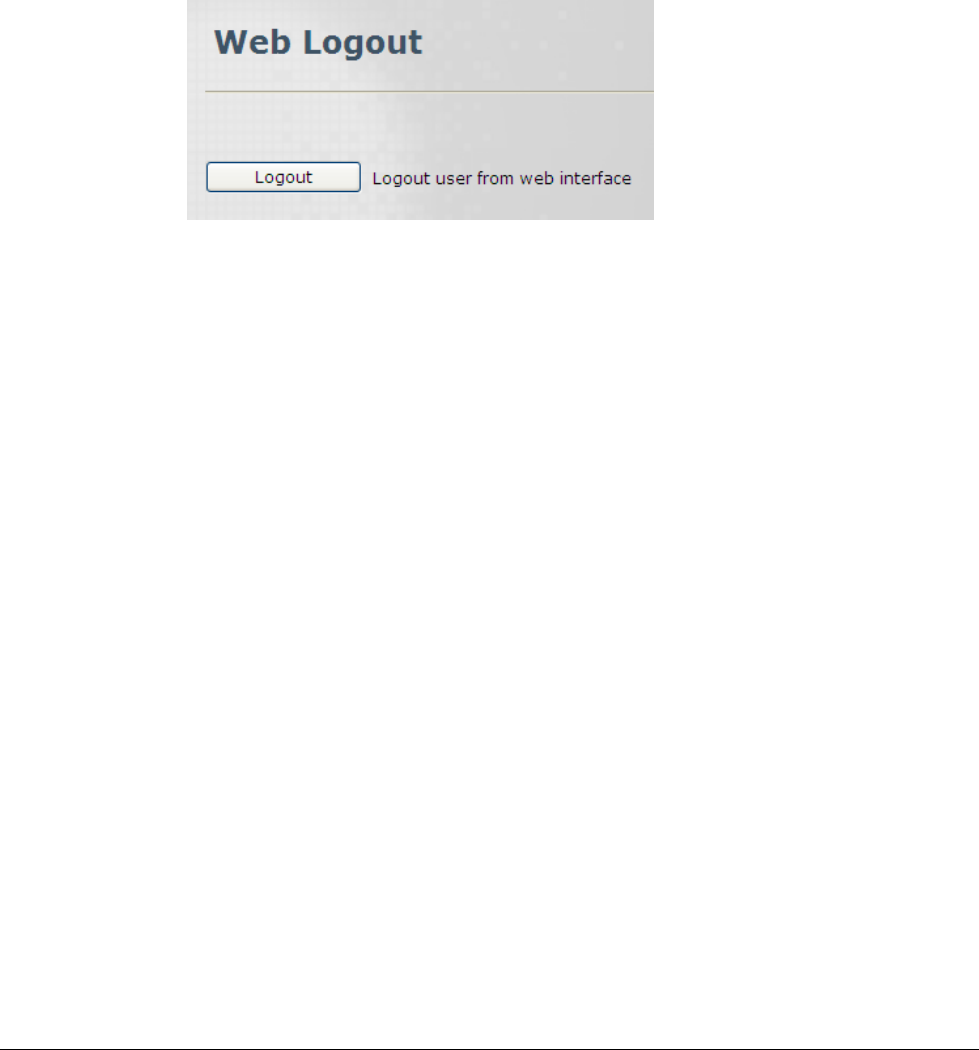
2.4 Logout
Logging out from the session is done through the logout pane.
To access the Logout pane
1. Click the Admin menu option and then the Logout sub-menu option.
2. In the displayed Logout pane click the Logout button.
© CalAmp Sentry 4G-900 pico Base Station 12 Backbone Configuration
3 Backbone Configuration
The Base Station backbone parameters provide infrastructure settings of the system mode and
other parameters. After configuring the system operation mode (Standalone or ASN-GW), the
corresponding backbone parameters can be configured.
The following backbone configurations are described in this chapter:
General parameters (system operation mode, Base Station and GW addresses)
Standalone mode: Switching parameters and learned MAC addresses
ASN-GW mode: Definition of ASN-GW to Base Station connection parameters (IP, tunneling,
keep-alive)
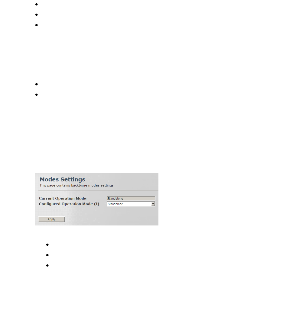
3.1 Setting the Operation Mode
The system can operate in two configurations:
Standalone mode
ASN-GW mode (Default)
The operation mode defines whether system operation (such as QoS capabilities) are performed
by the Base Station (Standalone mode) or by the ASN-GW (ASN-GW mode).
To access the Operation Mode pane
1. Click the Backbone menu option. The Backbone Admin sub-menu list is displayed in the
Sub-Menu option pane.
2. From the Backbone Admin sub-menus choose Operation Modes. The Operation Modes
pane is displayed.
3. To change the system operation mode:
In the Configured Operation Mode field choose the required mode.
Click Apply.
Restart the service to reset the operation mode to the configured value.
© CalAmp Sentry 4G-900 pico Base Station 13 Backbone Configuration
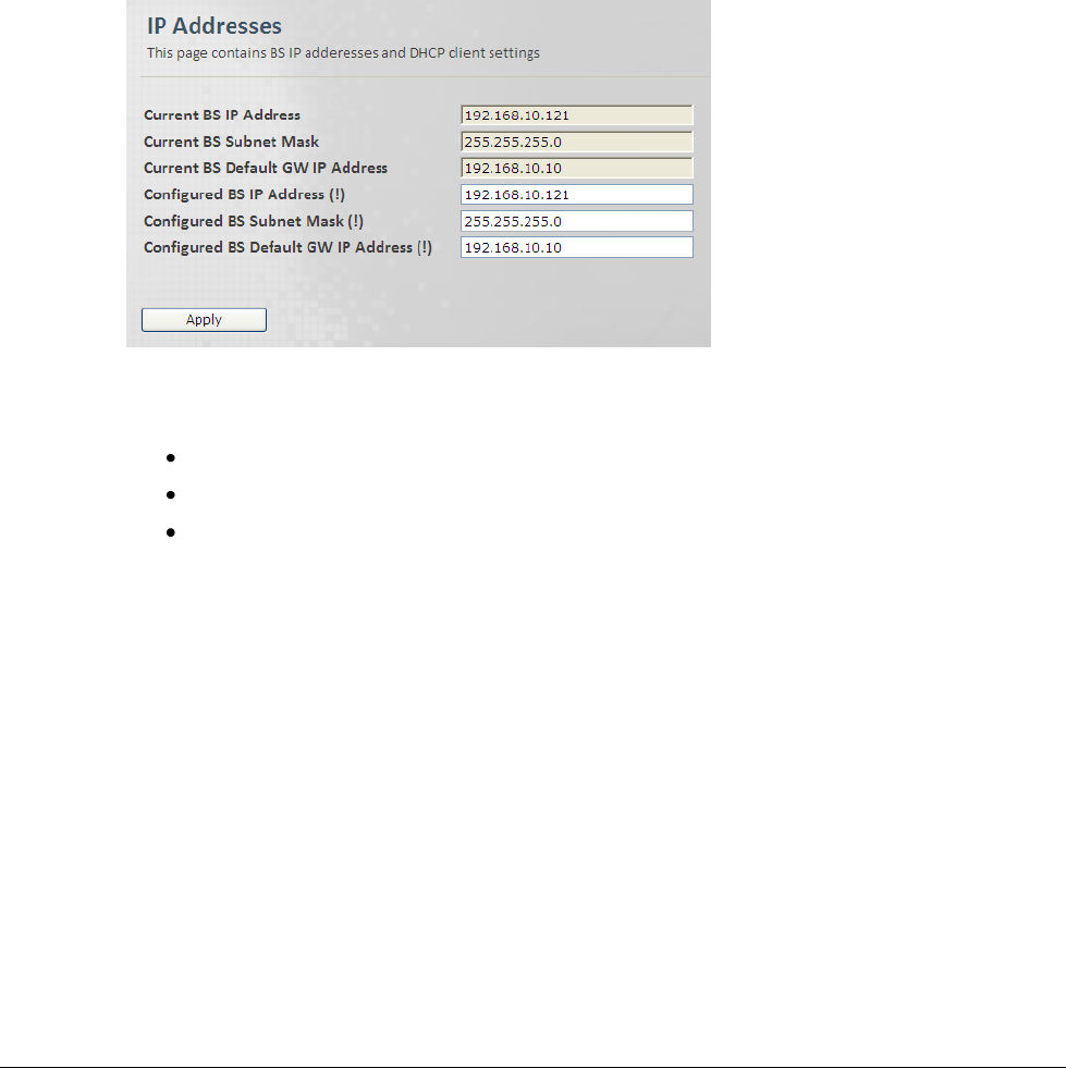
3.2 Base Station and ASN-Gateway IP Address
The Base Station and ASN-GW IP addresses and subnet mask are configured via the IP
Addresses pane..
To access the IP Addresses pane
1. Click the Backbone menu option. The Backbone Admin sub-menu list is displayed in the
Sub-Menu option pane.
2. From the Backbone Admin sub-menus choose IP Addresses. The IP Addresses pane is
displayed.
3. Define the required IP and subnet parameters and click Apply.
Base Station IP Address
Base Station Subnet Mask
Base Station Default GW IP Address
4. Restart the service to reset addresses according to the configured values.
3.3 Standalone: Switching parameters
The L2 switching related parameters define the L2 switching method, the MAC addresses table
used by the switching mechanism, and the MAC addresses aging period (after which an unused
MAC that appears in the table is ignored). These parameters are viewed and configured via the
Backbone Switching sub panes.
© CalAmp Sentry 4G-900 pico Base Station 14 Backbone Configuration
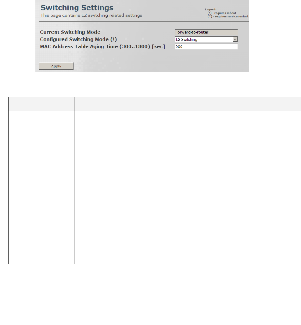
3.3.1 Switching Settings
This pane provides configuration options for the L2 Switching mode and for the MAC address
aging period.
To access the Switching Settings pane
1. Click the Backbone menu option and choose Switching and then Switching Settings from
the sub-menus. The Switching settings pane is displayed.
2. Define the required parameters according to the following descriptions and click Apply.
Field
Description
Current/Configured
Switching Mode
This parameter defines the traffic forwarding method:
L2 Switching mode: traffic flooding is enabled.
To dynamically learn about station locations, the Base Station listens to incoming
frames and keeps a table of address information by inspecting the source MAC
addresses. If the source MAC address is not in the address table already, it is
recorded in the table.
As a part of the forwarding decision, if destination MAC address is found, the
frame can be forwarded to that address. If the address is not found in the table,
the frame is flooded to all the CPEs (if it's a downlink packet) and to the CPEs
and network interface (if it's an uplink packet).
Forward-to-router mode (To be used for testing purposes only!!!): all traffic is
forwarded to the upstream router (no flooding). Do NOT use it.
Values: [L2 Switching; Forward-to-router]
MAC address Table
Aging Time
(300…1800) [sec]
Mac Address Table Aging period (in seconds), after which unused MAC address
entries will be dropped.
Values: 300-1800
© CalAmp Sentry 4G-900 pico Base Station 15 Backbone Configuration
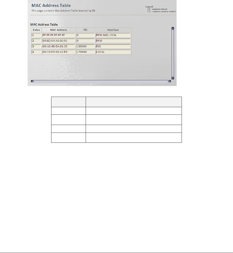
3.3.2 MAC Addresses Table
This is a read-only pane, and displays the MAC addresses learned by the Base Station, that are
used by the L2 switching mechanism.
To view the Switching MAC Addresses Table
1. Click the Backbone menu option and choose Switching and then MAC Addresses Table
from the sub-menus. The MAC Addresses Table pane is displayed.
2. The displayed information details are provided in the following table:
Field
Description
Index
Unique identifier
MAC Address
Base Station learned MAC addresses
TTL
Time to Live (for datagrams in the network)
Interface
Type of interface
© CalAmp Sentry 4G-900 pico Base Station 16 Backbone Configuration
3.4 ASN-GW Mode: ASN Settings
When the Base Station is in ASN-GW mode, it is required to define the backbone ASN-GW
parameters. These include the ASN-GW IP address, tunneling method (between the Base
Station and the ASN-GW), and the Base Station ASN keep-alive intervals.
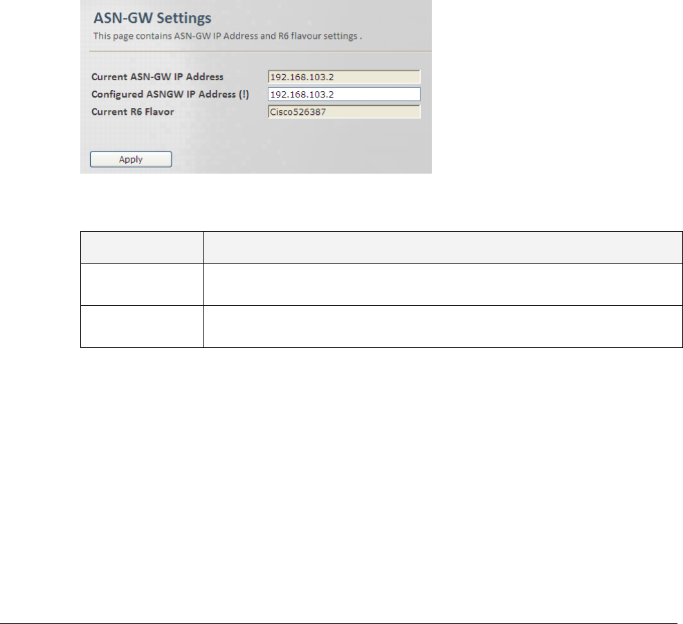
3.4.1 ASN-GW Link Settings
This pane provides configuration options for the ASN-GW IP and R6 parameters.
To access the ASN-GW Settings pane
1. Click the Backbone menu option and choose ASN Settings and then ASN-GW Settings
from the sub-menus. The ASN-GW settings pane is displayed.
2. Define the required parameters according to the following descriptions and click Apply.
Field
Description
ASNGW IP
Address
IP address to be used after configuration flashing or reboot.
Current R6
Flavor
Type of R6 tunneling used between the Base Station and the ASN-GW
(e.g. CiscoXXXXXX)
3. If the IP address has been configured, restart the service for the changes to be applied.
© CalAmp Sentry 4G-900 pico Base Station 17 Backbone Configuration
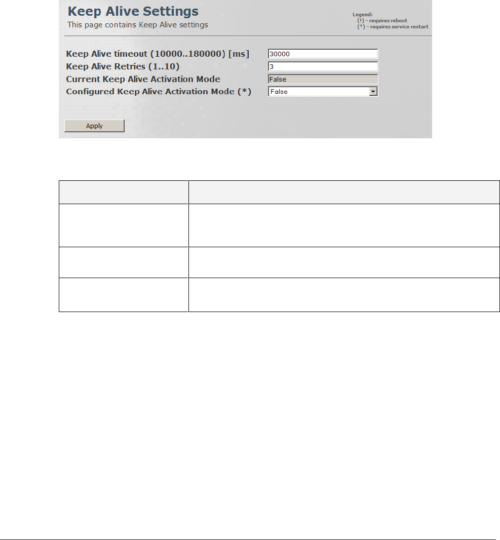
3.4.2 Keep Alive Settings
This pane provides configuration options for the keep-alive messages intervals and retries
protocol.
To access the Keep Alive Settings pane
1. Click the Backbone menu option and choose ASN Settings and then Keep Alive Settings
from the sub-menus. The Keep Alive settings pane is displayed.
2. Define the required parameters according to the following descriptions and click Apply.
Field
Description
Keep Alive timeout
(10000..180000) [µs]
This value indicates the time interval (in µSec) that a Base Station
waits for the keep-alive response before keep-alive request re-
transmission.
Keep Alive Retries (1..10)
Max number of keep-alive re-transmissions
Keep Alive Activation
Mode
Enable / Disable Keep Alive activation.
Values: [True, False]
3. If the Keep Alive Activation Mode has been configured, reboot the Base Station for the
changes to be applied.
© CalAmp Sentry 4G-900 pico Base Station 18 Administration
4 Administration
The following administration operations are described in this chapter:
View system information
Configure traps and SNMP options
Configure access permissions
Software version update operations
4.1 Viewing Device Status and Information
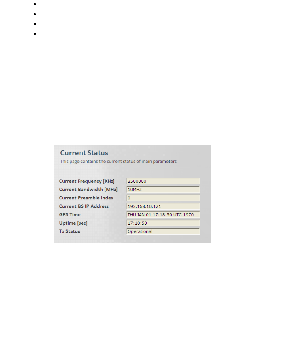
4.1.1 Main Status Pane
This pane provides status (read-only) information on the Base Station communication
parameters.
To access the Main Status pane
1. Click the Admin menu option. From the General sub-menus choose Current Status. The
Main Device Statuses pane is displayed.
© CalAmp Sentry 4G-900 pico Base Station 19 Administration
2. The displayed information details are provided in the following table:
Field
Description
Current Frequency [KHz]
Current Frequency in KHz
Current Bandwidth [MHz]
Current Operative BW in Mhz;
Must be one of the supported BWs
Current Preamble Index
Current Operative Preamble Index
Current Base Station IP Address
Current Base Station IP Address
Current ASN-GW IP Address
Current ASNGW IP Address
GPS Time
Time & Date in UTC; Source is Base Station GPS
Uptime [sec]
Running Time [sec] (from last restart)
Tx Status
Shows status of system operation.
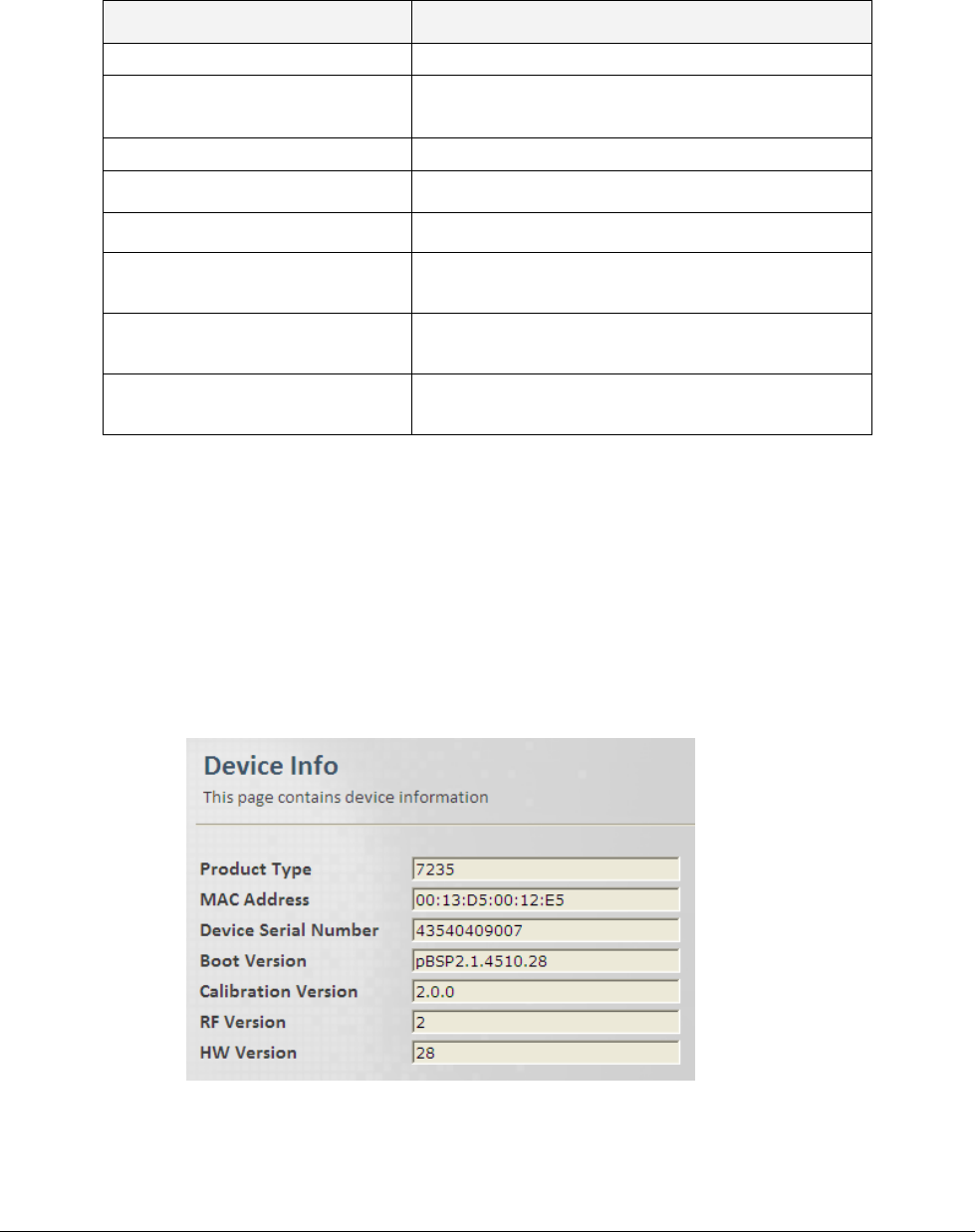
4.1.2 Device Info
This pane provides Base Station hardware identification information (read only) such as Device
Serial Number, Manufacturer identifier, etc.
To access the Device Info pane
Click the Admin menu option and then the General sub-menu option. From the General sub-
menus choose Device Info. The Device Info pane is displayed.
© CalAmp Sentry 4G-900 pico Base Station 20 Administration
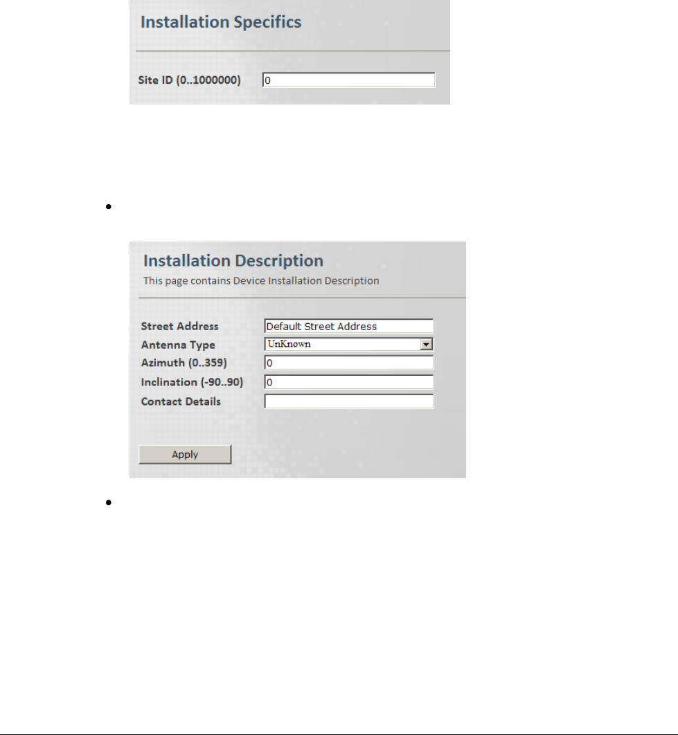
4.2 Base Station Identification Information
This information includes the site ID, Base Station location and antenna details.
To define Base Station identification information
1. Click the Admin menu option, the General sub-menu option and then choose Installation
Specific. The Installation Specifics
2. Define the Site ID as defined by the Network Operator and click Apply.
Several Base Station may have the same site ID. Values: [0,1000000]
3. Enter more descriptions on the location of the Base Station:
Choose Installation Description (from the Admin menu, General sub-menus). The
Installation Description pane appears.
Define the fields and click Apply:
o Address of Base Station (up to 30 characters)
o Antenna type: Omni, Directional or Unknown
o Antenna Azimuth in degrees, as configured by the installer: 0 to 359
o Inclination: Vertical inclination of antenna in degrees, as configured by the installer.
Values: [-90,90]
o Contact details: name, telephone ,etc. of service person that can be contacted.
© CalAmp Sentry 4G-900 pico Base Station 21 Administration
4.3 Security
The Base Station is secured through access permissions and SNMP definitions. Up to three
authentication levels are supported, where additional users can be defined according to the
default authentication profiles.
4.3.1 Available Authentication Levels
Three authentication levels are available:
Admin – highest level. Has access to all read and write options, including user definitions.
Supervisor – has access to all Read and Write options except for User Definitions.
Technician – has access to all Read options and limited access to configuration options.
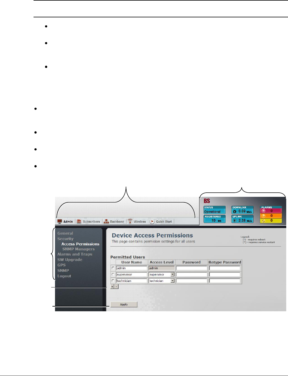
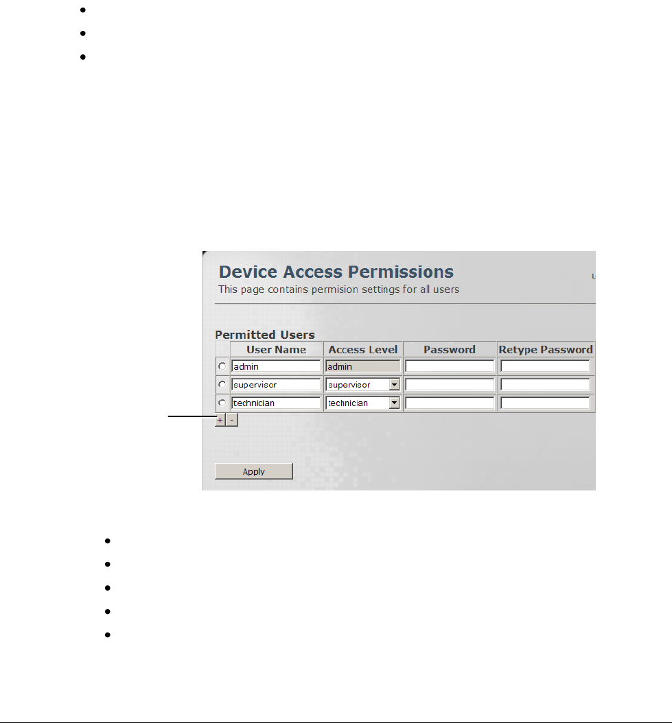
4.3.2 Defining Users and their Access Permissions
This pane is used by the system administrator to define Base Station users granted with relevant
permissions.
To view the Access Permissions pane
1. Click the Admin menu option and then the Security sub-menu option. From the Security
sub-menus choose Access Permissions. The Access Permissions pane is displayed.
2. To Add a user:
Click the “+” sign at the bottom of the Users Table.
Enter the new User Name.
Select the relevant access level for that user.
Enter and retype the Password.
Click Apply.
Click to add
users
© CalAmp Sentry 4G-900 pico Base Station 22 Administration
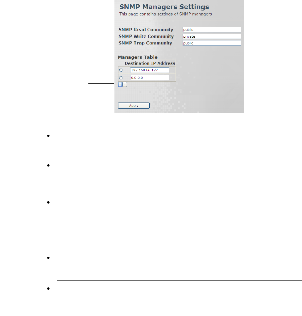
4.3.3 SNMP Settings and Trap Destination Addresses
This pane is used to define the IP destination addresses and the minimal severity of events sent
to the corresponding IP Address destination.
Up to five IP Destination Addresses can be defined.
To access the SNMP Managers pane
1. Click the Admin menu option and then the Security sub-menu option. From the Security
sub-menus choose SNMP Managers. The SNMP Managers pane is displayed.
2. Define the required parameters according to the following descriptions.
SNMP Read Community - can be used as a password to secure information retrieval.
Public – no password (default)
Private – password can be assigned
SNMP Write Community - can be used as a password to secure performing set
commands.
Public – no password (default)
Private – password can be assigned
SNMP Trap Community - You can configure the SNMP service to send a trap when it
receives a request for information that does not contain the correct community name and
does not match an accepted host name.
Public – no password (default)
Private – password can be assigned
3. Add the IP Destination Addresses – these are the addresses to which traps will be sent:
Click the + sign to add a row to the table.
Note: To remove the last row, click the “–“ sign. To remove a selected row, mark the required row
and then click the “–“ sign.
Define the IP Destination Address to which the traps will be sent and click Apply.
Click to add IP
Destination Address
© CalAmp Sentry 4G-900 pico Base Station 23 Administration
4.4 Alarms and Traps
Use the Web Manager to view a summary of the currently generated alarms. You can also
disable irrelevant alarms.
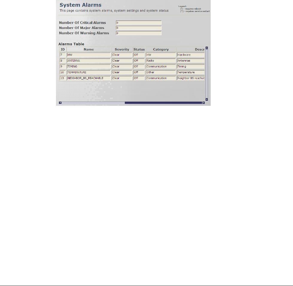
4.4.1 Viewing a Summary of System Alarms
This read-only screen provides a summary of the current system alarms.
To access the Alarms pane
1. Click the Admin menu option and then the Alarms and Traps sub-menu option. From the
Alarms and Traps sub-menus choose Alarms. The System Alarms pane is displayed.
© CalAmp Sentry 4G-900 pico Base Station 24 Administration
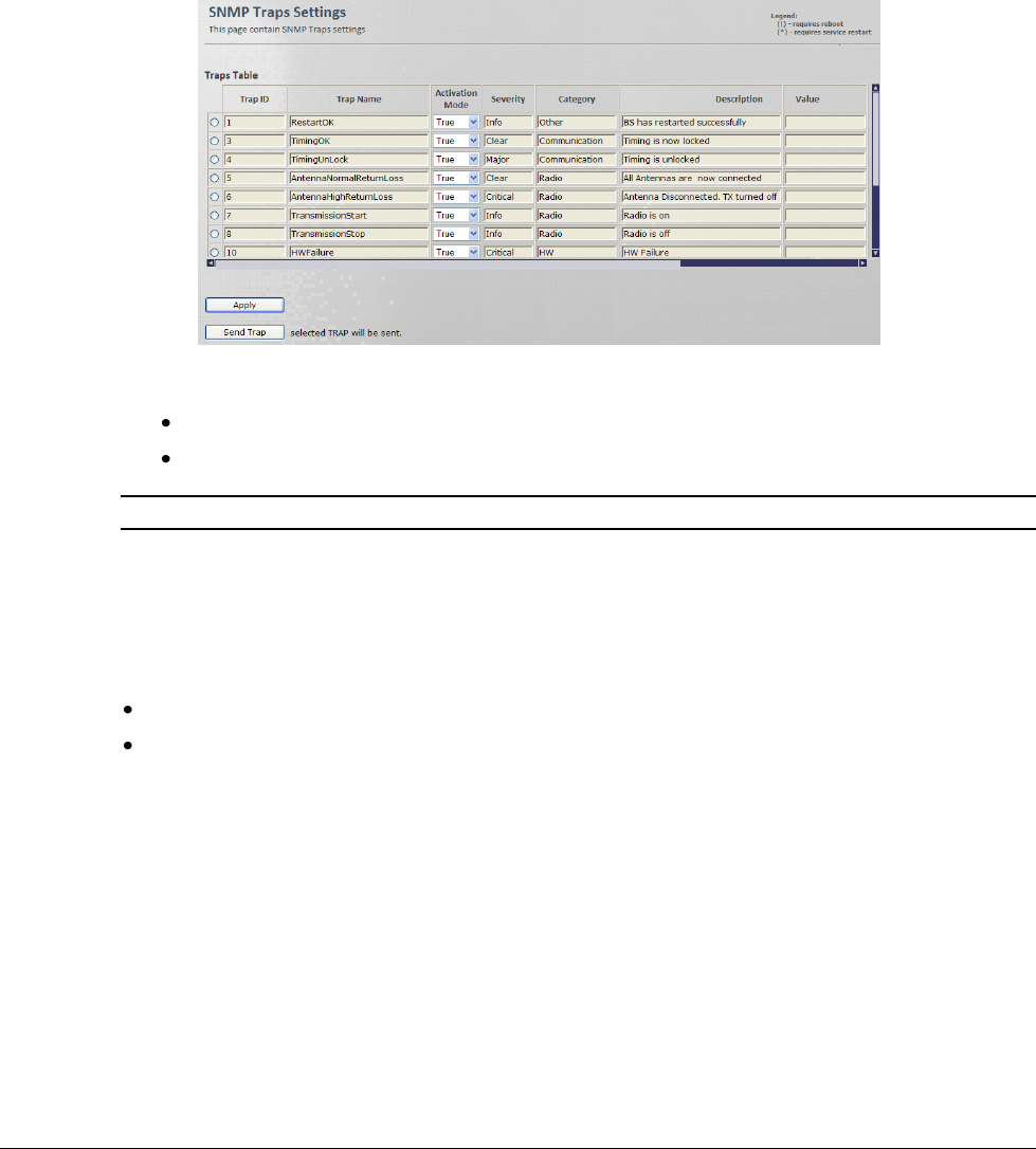
4.4.2 Traps – SNMP Trap Settings
Use this pane to select the traps that will be supported by this Base Station.
To access the Traps pane
1. Click the Admin menu option and then the Alarms and Traps sub-menu option. From the
Alarms and Traps sub-menus choose Traps. The SNMP Traps Settings pane is displayed.
2. Select the traps to be supported by this unit as follows:
Set the Activation Mode of the relevant trap to True.
Click Apply.
Note: Use the Send Trap button to send the trap to the defined Destination Addresses.
4.5 Software Versions Management
Two software versions are stored on the Base Station s:
One in the Main Directory
One in the Secondary Directory
The Base Station can run software from either the Main or the Secondary directory as
determined by the user; however, software from the Main directory is always run upon Base
Station reboot or reset.
Therefore, it is recommended to run the desired software from the Main directory.
The software components saved in one directory can be copied to the other directory, allowing
the user to save backups of software versions and to restore or update versions as required.
This sections describes how to perform these operations, navigating between both directories
and external URL locations.
© CalAmp Sentry 4G-900 pico Base Station 25 Administration
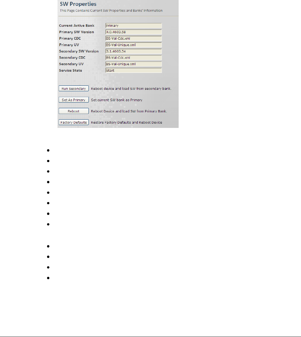
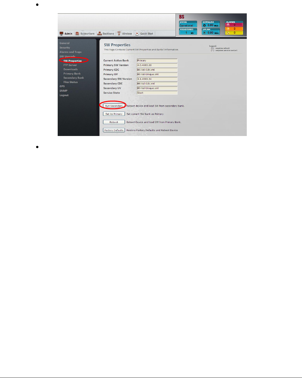
4.5.1 Activating Software Versions
This pane shows which software versions are currently loaded and provides options for switching
between the main and secondary software versions.
To access the SW Operations pane
1. Click the Admin menu option and then the SW Upgrade sub-menu option. From the SW
Upgrade sub-menus choose SW Properties. The SW Properties pane is displayed.
2. The following information is provided:
Current Active Bank - Primary or Secondary.
Primary SW version
Primary CDC
Primary UV
Secondary SW version
Secondary CDC
Secondary UV
Service State
3. The following operations can be performed:
Run Secondary - Reboot device and load from secondary
Set as Primary - Set current running SW as Primary
Reboot - Reboot device and load from main
Factory Defaults – Restore factory setup
© CalAmp Sentry 4G-900 pico Base Station 26 Administration
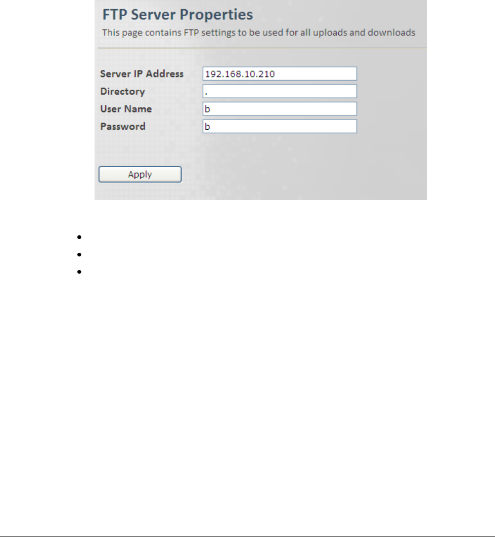
4.5.2 FTP Server Configuration
Use this pane to define the location and access information of the FTP server in which software
versions are stored.
To define the FTP Server parameters
1. Click the Admin menu option and then the SW Upgrade sub-menu option. From the SW
Upgrade sub-menus choose FTP Server. The FTP Server Properties pane is displayed.
2. Define the FTP server parameters described below and click Apply:
Server IP Address
Directory – directory in which files are located
User Name and Password – your FTP User Name and Password.
© CalAmp Sentry 4G-900 pico Base Station 27 Administration
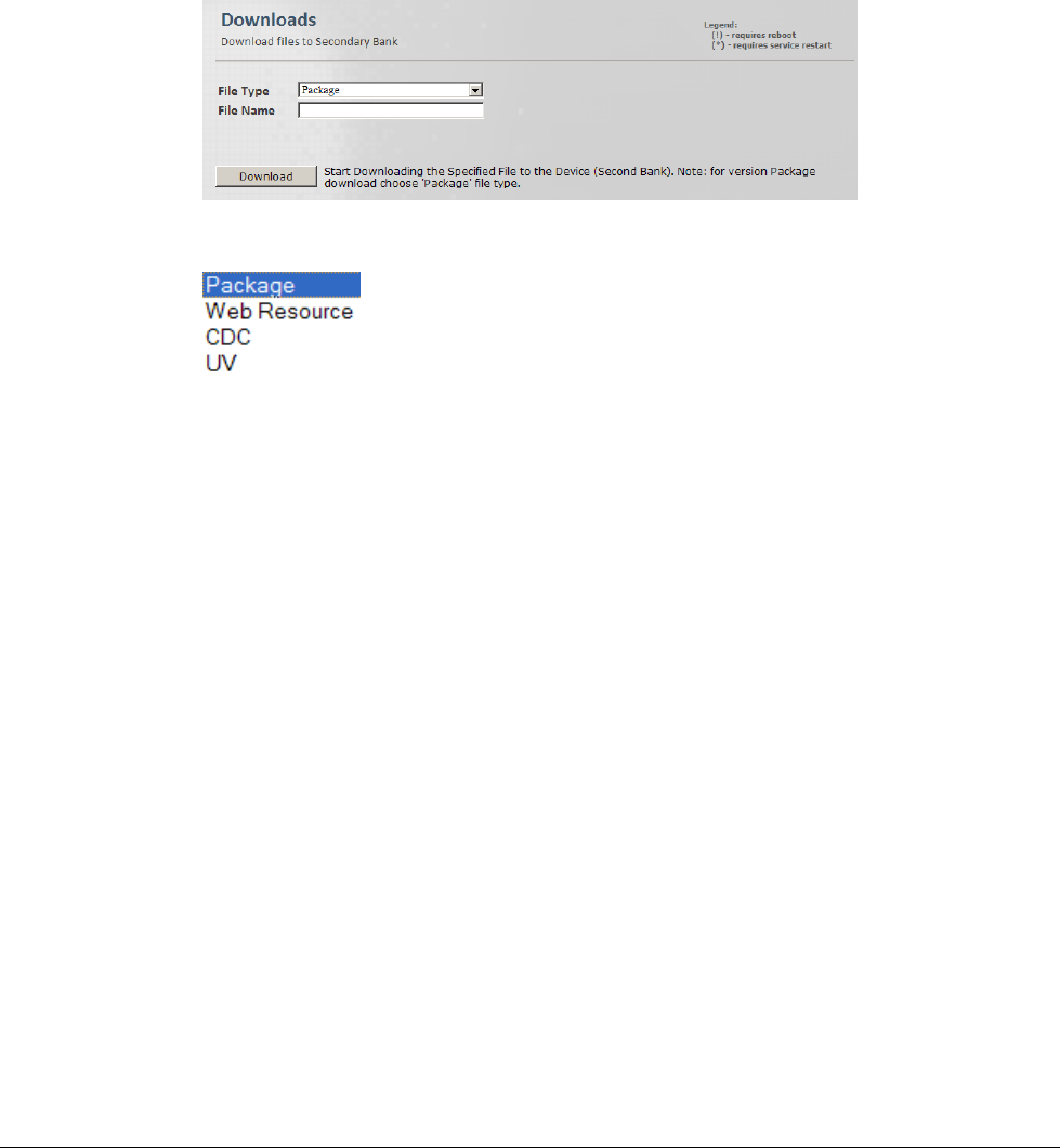
4.5.3 Downloading Software Versions
This pane is used to download a new SW version from the FTP server to the Base Station
Secondary SW directory.
To download SW to the Base Station Secondary SW directory
1. Click the Admin menu option and then the SW Upgrades sub-menu option. From the SW
Upgrades sub-menus choose Downloads. The SW Downloads pane is displayed.
2. Select the Type of File to be downloaded:
3. In the Download File Name, enter the name of the file to be downloaded.
4. Click Download. The specified file will be downloaded from the predefined FTP server to the
BTS Secondary SW directory.
© CalAmp Sentry 4G-900 pico Base Station 28 Administration
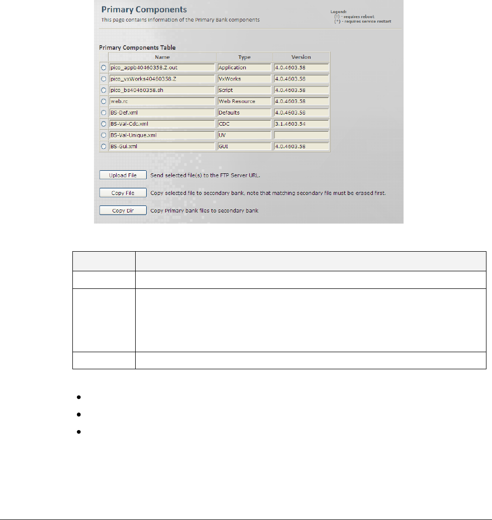
4.5.4 Managing Main Software Components
This pane provides options for copying selected Main software files to a user defined URL or to
the Base Station Secondary software directory.
To access the Primary Bank (Main Version) pane
1. Click the Admin menu option and then the SW Upgrade sub-menu option. From the SW
Upgrade sub-menus choose Primary Bank. The SW Primary Version Components pane is
displayed.
2. Update the required parameters in the Pane table according to the following descriptions.
Field
Description
Name
SW Component Name (e.g. Base Station -GUI, etc.)
Type
Type of the SW component.
Values:
Package, Application, VxWorks, Blob, Script, Web Resource, Defaults,
CDC, Regulation, UV, GUI
Version
SW Component Version
3. Click one of the buttons:
Upload File - Send selected files to the specified URL
Copy File - Copy selected file to secondary.
Copy Dir - Copy main zone files to secondary zone.
© CalAmp Sentry 4G-900 pico Base Station 29 Administration
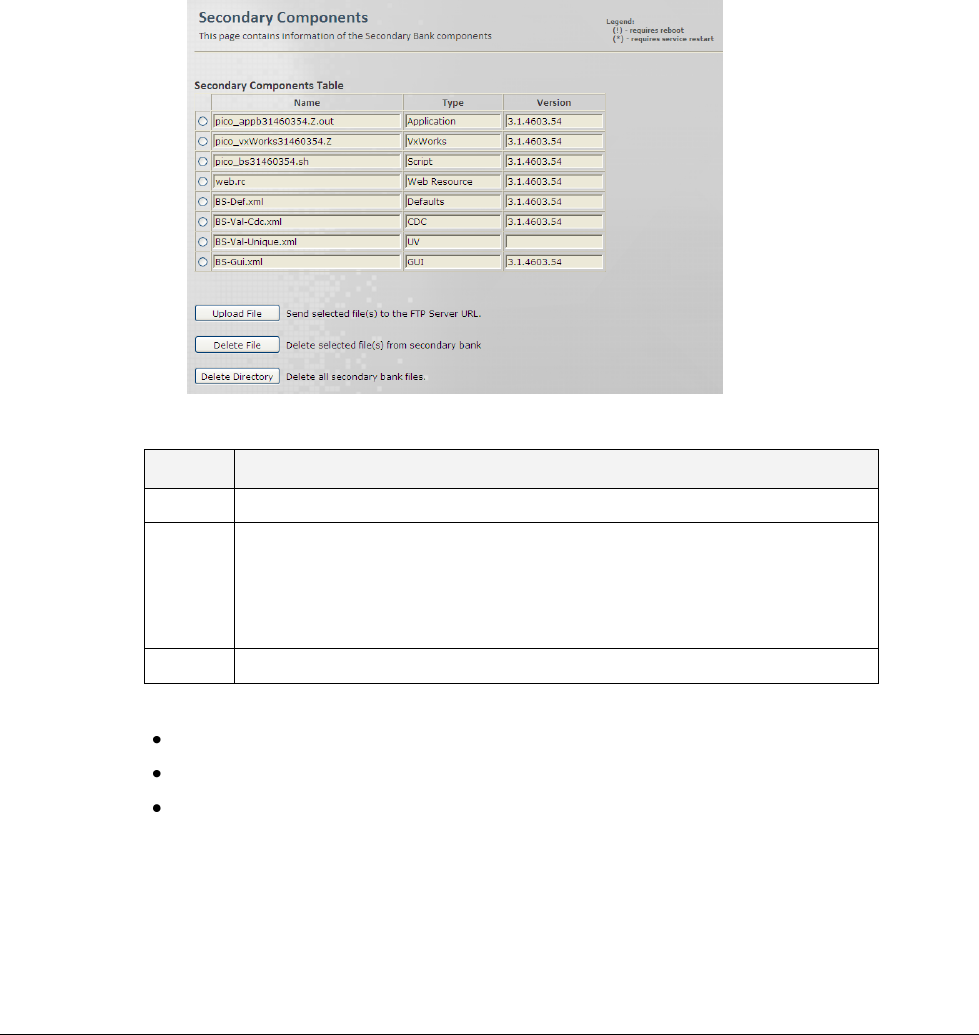
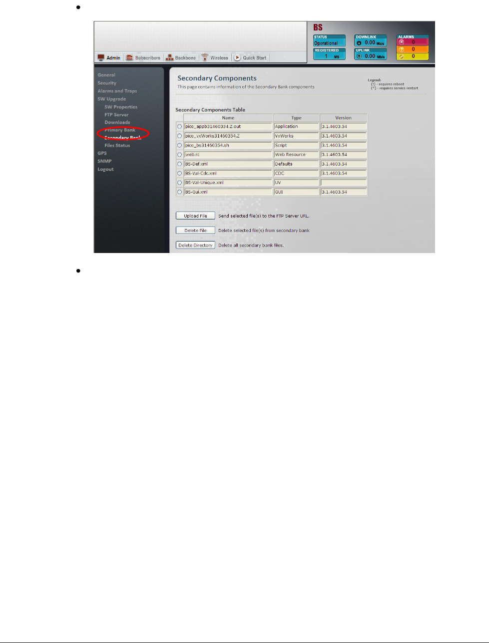
4.5.5 Managing Secondary Software Version Files
This pane provides options for uploading selected Secondary software version files to a specified
URL and for removing selected files.
To access the Secondary Bank (Version) pane
1. Click the Admin menu option and then the SW Upgrade sub-menu option. From the SW
Upgrade sub-menus choose Secondary Bank. The SW Secondary Bank Components pane
is displayed.
2. Update the required parameters in the Pane table according to the following descriptions.
Field
Description
Name
SW Component Name (e.g. BSP, CPLD )
Type
Type of SW component.
Values:
Package, Application, VxWorks, Blob, Script, Web Resource,
Defaults, CDC, Regulation, UV, GUI
Version
SW Component Version
3. Click one of the buttons:
Upload File - Send selected files to the specified URL
Delete File - Delete selected file from the secondary storage.
Delete Directory - Delete all secondary files.
© CalAmp Sentry 4G-900 pico Base Station 30 Administration
4.5.6 Upgrade from Version 3.0.4602.yy
This procedure consists of the following steps:
1. Automatically loading a set of files as a package to the secondary directory
2. Running the version and verifying unit operation.
3. Setting the version to run from the Main directory.
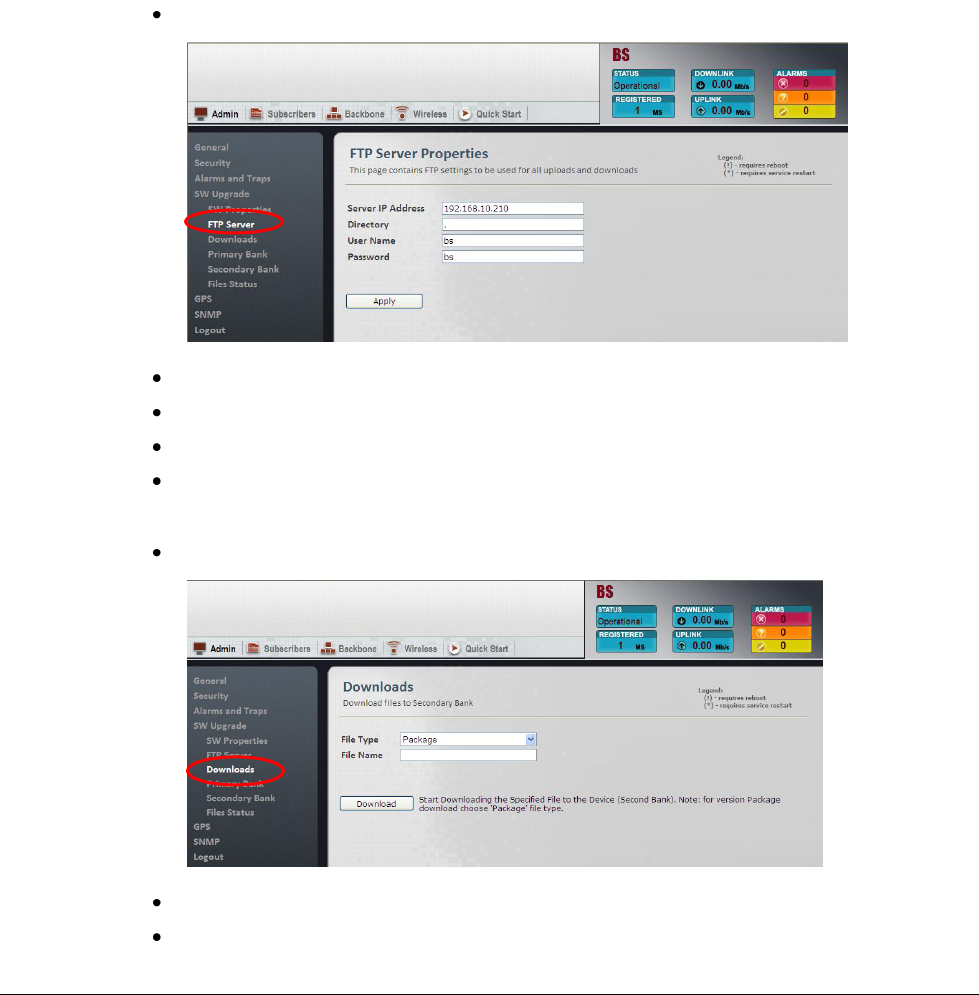
4.5.6.1 Loading the New Version to the Secondary Directory
1. Configure FTP server from which the new software file will be downloaded:
From the Admin menu, select SW Uprade and choose FTP Server.
Type the IP of the FTP server.
Type the directory on which the software file is stored
Type your FTP Server User Name and Password.
Click Apply.
2. Download the files to the Secondary Directory by doing the following:
In the left pane, under SW Upgrade, click Downloads.
Select the File Type as Package.
Click Download to begin the process.
© CalAmp Sentry 4G-900 pico Base Station 31 Administration
3. Verify that the downloaded version is saved into the Secondary Directory:
Under SW Upgrade, choose Secondary Bank.
Under Secondary Components Table, verify that the software components are
downloaded to the Secondary directory.
© CalAmp Sentry 4G-900 pico Base Station 32 Administration
4.5.6.2 Running the New Software Version
Run the Secondary software version:
Under SW Upgrade, choose SW Properties.
Click Run Secondary. The Base Station will reset and the Secondary files will be loaded.
This will take about 2 minutes.
© CalAmp Sentry 4G-900 pico Base Station 33 Administration
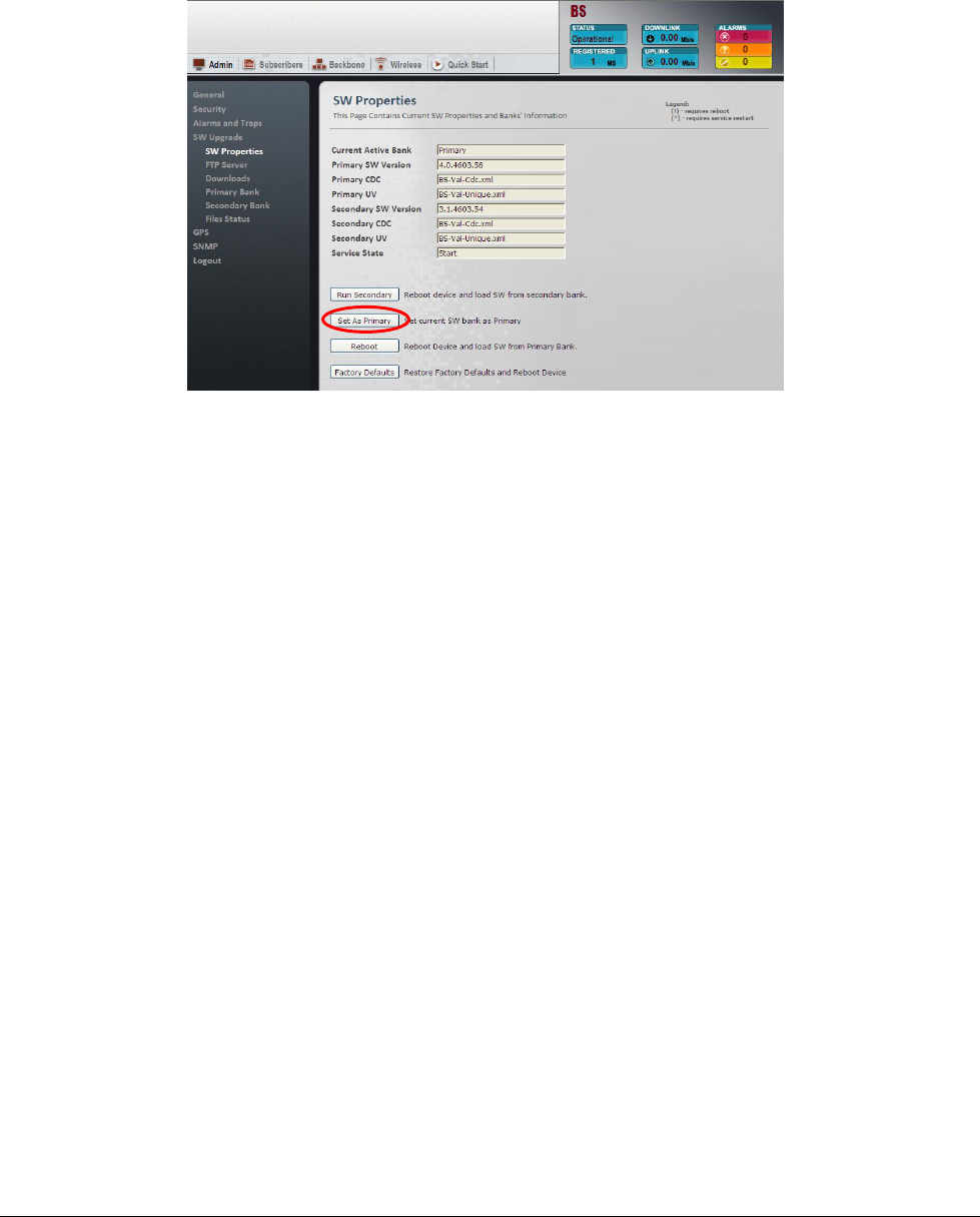
4.5.6.3 Setting the Version to Run from the Primary Directory
Click Set as Primary. The software files will run from the Primary directory.
The Software Upgrade procedure is now complete.
© CalAmp Sentry 4G-900 pico Base Station 34 Administration
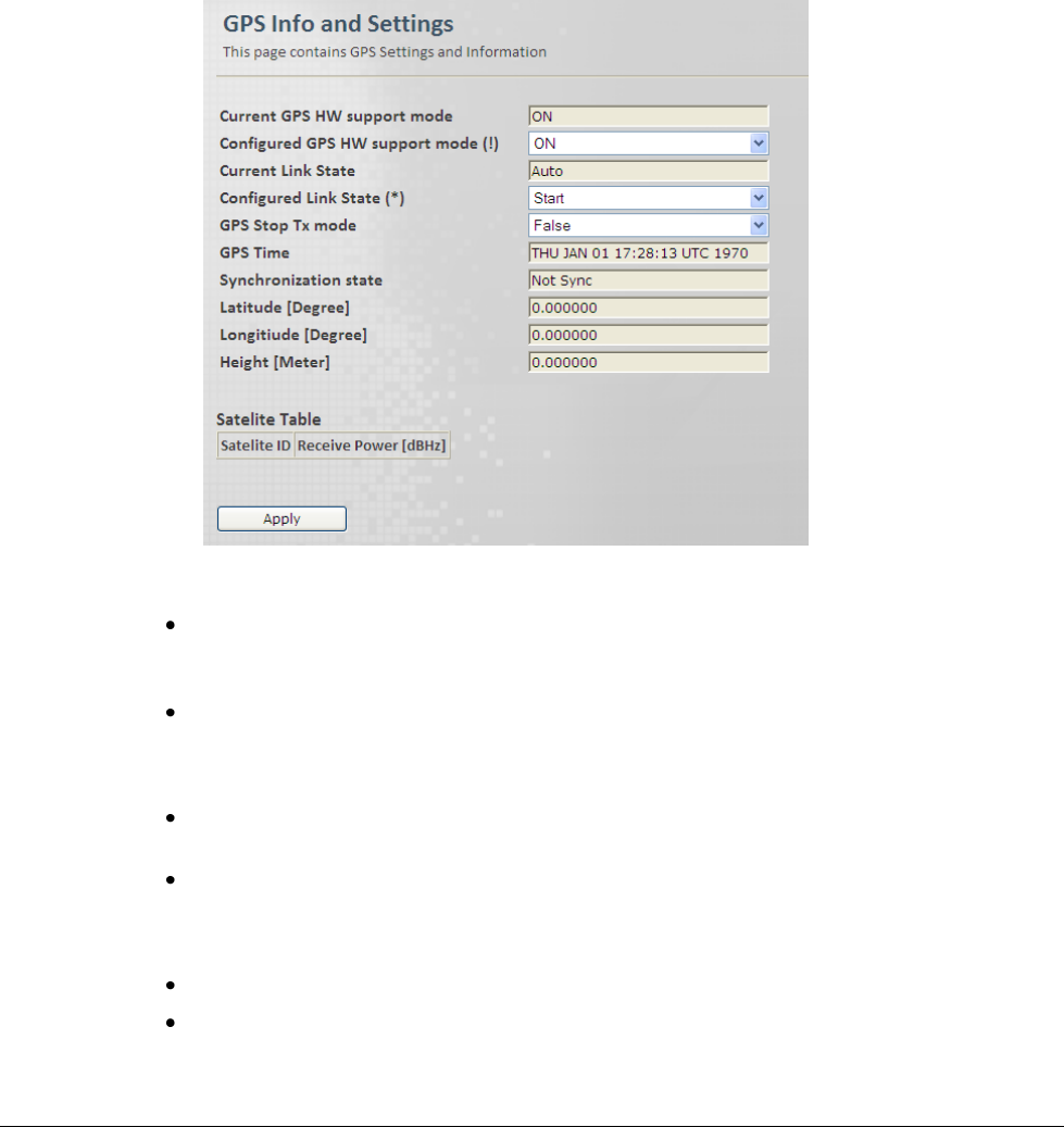
4.6 GPS Settings
The Base Station is set up by default, to operate with GPS. This section provides instructions on
disabling the GPS for troubleshooting purposes or for lab operation conditions.
To access the GPS Info and Settings pane
1. Click the Admin menu option and then the GPS sub-menu option. From the GPS sub-menus
choose Info and Settings. The GPS Info and Settings pane is displayed.
2. To disable (or re-enable) the GPS, set the GPS HW Support mode and click Apply:
OFF - used in special cases. System does not attempt to synchronize with GPS. For
example, for maintenance, or installations with a single Base Station. Or in cases where
GPS is not relevant and we do not want device to continuously attempt to synchronize.
ON – normal operation.
3. To troubleshoot or for maintenance, use the Link State option – used for troubleshooting or
for turning off Tx during maintenance. (Values: Stop, Start, Auto)
Auto – Default. Transmission is codependent on GPS and cannot be interrupted. Tx is
stopped only if GPS is not synchronized (not controlled by user).
Start and Stop – used to start and stop Tx.
4. Set the GPS Stop Tx mode - Determine if the Base Station will continue transmitting after
hold over.
False – off. Default.
True – on. Base Station continues transmitting after hold-over.

© CalAmp Sentry 4G-900 pico Base Station 35 QoS Management
5. The remaining parameters are read-only and provide information on the GPS status and
location.
5 QoS Management
NOTE: The QoS capabilities are only relevant for Standalone configuration. In ASN-GW mode,
QoS management is performed through the ASN-GW.
By default, Subscriber Stations (SS) are assigned a Best Effort (BE) service profile for the UL
and DL channels. Only the maximum bandwidth can be configured for the default service profile.
In addition, any SS can be assigned a number of user defined uplink and downlink Service Flows
(SF) that together make up the service profile corresponding to the QoS requirements of that SS.
For example, a profile can consist of the following service flows: a flow matching VoIP needs,
another matching video conferencing needs and a third matching web browsing needs.
The service flows are defined and allocated as SS profiles through the Subscribers set of
screens.
5.1 QoS Definition Flow
The steps below summarize the procedure for defining SFs and assigning them to SSs (as a
QoS profile):
1. Define a set of Service Flows (SFs) for the UL and for the DL.
2. For each SF define the relevant attributes: Classification-Rule-Priority, Scheduling, Min and
Max rates, Latency, etc.
3. For each defined SF, you may define relevant classifiers. These are used to determine the
traffic to which this rule (SF) will be applied.
The traffic can be defined according to the source of traffic or according to the type or any
(logical OR) combination: DSCP range, port range, IP address source or destination, etc.
4. Define the MAC address of the SS to which the SFs will be assigned.
5. Define a QoS profile to the selected SS by assigning it the relevant Service Flows.
Note: For every SF change, it is required to perform service-restart to any CPE to which that SF
has been allocated.
© CalAmp Sentry 4G-900 pico Base Station 36 QoS Management
5.2 Defining Service Flow(s)
Any number of service flows can be defined for the uplink and for the downlink. The Service
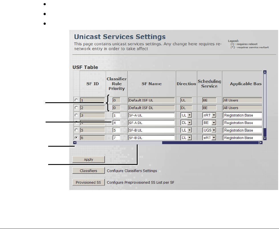
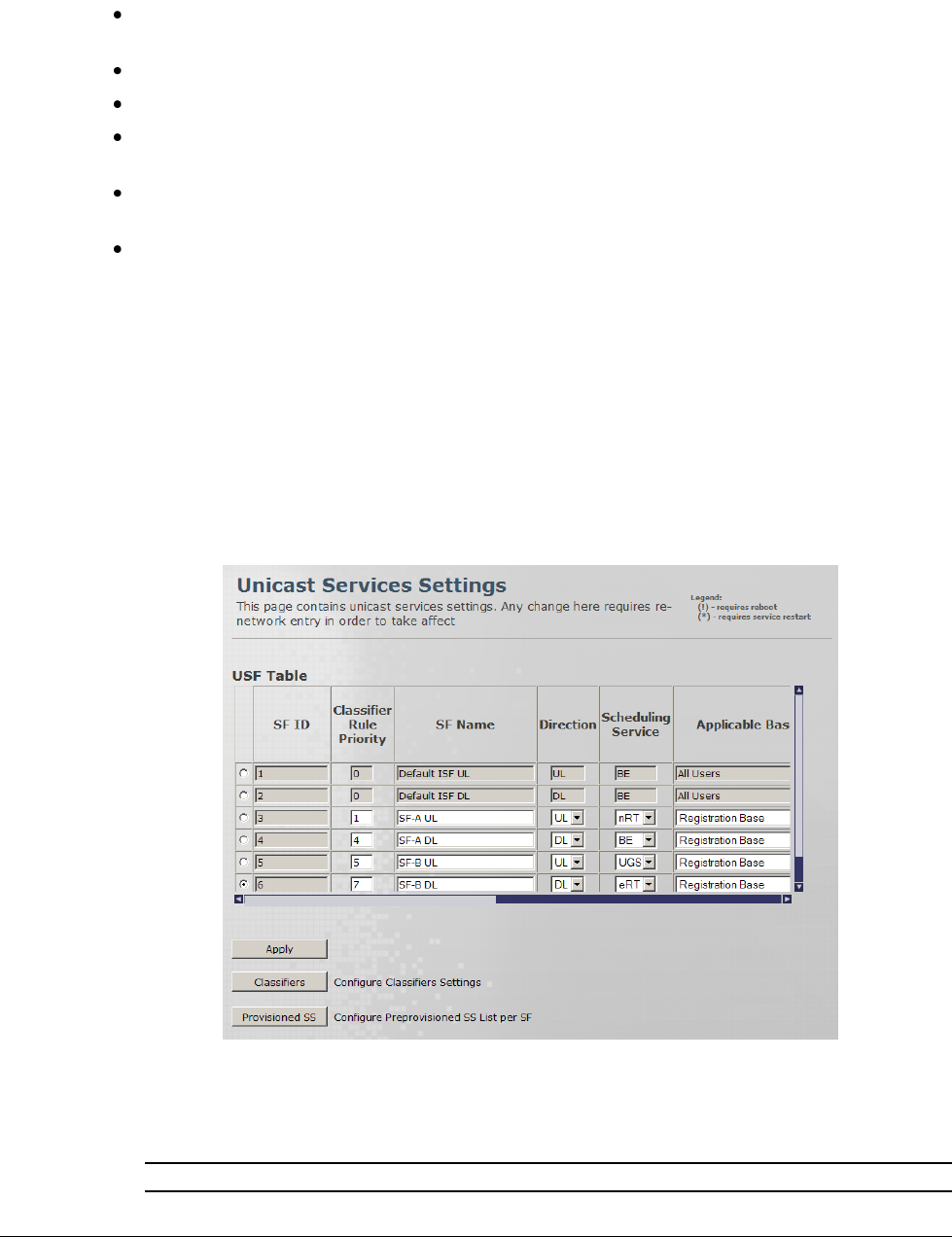
Flows are defined via the Unicast Services Setting screen.
5.2.1 The Unicast Service Pane
The Unicast Service Settings pane is used to define a pool of Service Flows, where each flow
can be assigned a range of attributes. Selected SFs are then assigned to defined Subscriber
Stations to create SS specific profiles.
To access the Unicast Services pane
Click the Subscribers menu option, from the Subscribers sub-menus choose Services. The
Unicast Services Settings pane appears.
The pane lists the two default SFs and provides options adding more SFs.
The following operation buttons are available:
Apply – implements changes on the selected row.
Classifiers – invokes classifier-definition-screen (relevant to the selected row).
Provisioned SS – shows the SS associated with the selected SF.
Click to add SF
Example: SF-A
defined
Scroll to view
more attributes
Default SFs
© CalAmp Sentry 4G-900 pico Base Station 37 QoS Management
Working with the Unicast Service Settings pane
The top two rows display the default (BE) UL and DL Service Flows and their attributes. Only
the Max BW value can be modified for the default SFs.
Up to 30 rows can be added (by clicking the '+' sign).
Each SS can be assigned up to 4 SFs
To add a Service Flow, click the (+) sign at the bottom of the table, define the parameters
and click Apply.
To delete a Service Flow – select the radio-button in the relevant row and click the (-) sign at
the bottom of the table.
After performing any change in SF definition, the CPE is required to re-access the network
for changes implementation.
5.2.2 Defining Service Flows
The default SF do not provide QoS to the Subscriber Station. QoS is only provided by assigning
the SS a profile based on the user defined Service Flows. This section describes how to define
SFs and the available attributes.
To define a Service Flow
1. Click the Subscribers menu option, from the Subscribers sub-menus choose Services. The
Unicast Services Settings pane appears.
2. Add an SF (row) by clicking the (+) sign.
3. Configure the SF attributes according to the descriptions in the following table and then click
Apply.
Note: If Classifiers are to be assigned, click the Classifiers button AFTER clicking Apply.

© CalAmp Sentry 4G-900 pico Base Station 38 QoS Management
Field
Description
SF ID
Read only. Service Flow ID automatically provided by the system after applying
the changes.
Classification Rule
Priority
Classification rule priority: 0 to 255
The Priority Level determining how the SF data will be classified.
The same priority can be assigned to an UL and to a DL SF. The Classification
Rule Priority must be unique for each SF UL or SF DL. This parameter is related to
the selected classifer.
SF Name
User assigned unique name identifying the Service Flow. The name should
include the SF direction (UL or DL).
Direction
Direction to which SF is assigned - Downlink or Uplink
Scheduling Service
Service Scheduling Flows supported by WiMAX.
Service Flow
Designation
Defining QoS
Parameters
Application Examples
UGS - Unsolicited Grant
Services
Maximum sustained rate
Maximum latency
tolerance
Jitter tolerance
Voice over IP (VoIP)
without silence
suppression
RT – Real-Time Polling
service
Minimum reserved rate
Maximum sustained rate
Maximum latency
tolerance
Traffic priority
Streaming audio and
video, MPEG (Motion
Picture Experts Group)
encoded
nRT – Non-Real-Time
Polling service
Minimum reserved rate
Maximum sustained rate
Traffic priority
File Transfer Protocol
(FTP)
BE – Best-effort service
Maximum sustained rate
Traffic priority
Web browsing, data
transfer
eRT – Extended-Real-
Time Polling service
Minimum reserved rate
Maximum sustained rate
Maximum latency
tolerance
Jitter tolerance
Traffic priority
VoIP with silence
suppression
Applicable Base
Determines the group of subscribers to which the SF will be assigned.
Registration Base - assigns the SF to the explicitly configured (registered) SS.
All Users - this SF will be applied to all subscribed SSs. Select this option to set
this as the default profile.
Min Rate [Kbits/sec]
Minimum bandwidth rate for this SF.

© CalAmp Sentry 4G-900 pico Base Station 39 QoS Management
Max Rate [Kbits/sec]
Maximum rate for this SF. A value of „0‟ provides unlimited rate.
Max Latency [µsec]
(UGS, RT, eRT)
Relevant only for UGS, RT and eRT. A value of „0‟ does not put a limit on latency.
Maximum Latency (delay) for this SF. Set value according to the type of service
(i.e. <100ms for Voice and Video applications.
Unsolicited Grant [µsec]
Interval (UGS, eRT)
Relevant if the UGS – UGI - TBD
A value of „0‟ provides unlimited UGI.
Tolerated Jitter (UGS
only) [µsec]
the UGS tolerated jitter parameter…. A value of „0‟ does not put a limit on jitter.
Unsolicited Polling
Interval (RT, nRT)
[µsec]
The maximal nominal interval between successive polling grants opportunities for
this Service Flow, especially used for silence period of VoIP traffic with silence
suppression.
Has Classifiers
Read only. Displays whether or not this SF is assigned Traffic Classifiers.
Values: [True, False]
To configure the SF Classifiers see 5.2.2.2.
4. If required, define the Traffic classifiers according to the following section.
5. Reset the SS-Base Station connectivity:
Resetting the connection of a single SS (in case the SF is applied on a Registration
Base):
Click the Subscribers menu option. Choose the Subscriber Management sub-menu
and then the Registered SS.
In the displayed Registered SS Information pane select the radio button of the
requested SS and click the Deregister button.
Resetting the connection of all registered SSs (in case the SF is applied to All Users):
Click the Quick Start menu option.
In the displayed Quick Start pane click the Stop Service button, and then click the Start
Service button.
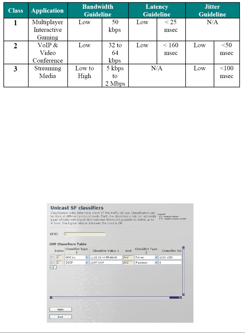
5.2.2.1 Bandwidth Latency and Jitter Guidelines
© CalAmp Sentry 4G-900 pico Base Station 40 QoS Management
5.2.2.2 Defining Traffic Classifiers for the SF
The Unicast Classifier pane is used to select the traffic to which the SF will be applied. The traffic
can be selected according to various parameter types: traffic source and destination, DSCP and
IP protocol.
Up to four classifiers can be defined for each SF where the data is analyzed according to each of
the classifiers (logical 'OR') assigned to the SF. Each classifier consists of either one or two
filtering values (e.g. traffic source from a specific IP address and a specific Port, DSCP range of
traffic type, etc.), where the classifier is defined according to both (logical 'AND').
To define Unicast SF Classifiers
1. (If you are not already in the Unicast Services pane), access the Unicast Services pane (by
clicking the Subscribers menu option and choosing Services from the sub-menu).
2. Select the relevant SF row and click the Classifiers button. The Unicast SF Classifiers
screen appears.
© CalAmp Sentry 4G-900 pico Base Station 41 QoS Management
The following operation buttons are available:
Apply – used to apply changes to selected classifier
Back – go back to the SF screen (to choose another SF).
3. Click the '+' sign to add a new row.
4. Update the required parameters in the Pane table according to the following descriptions and
click apply to implement the changes for each row.
NOTE: Once the classifier for the SF has been defined, the SF configuration is complete and the SF
can be assigned to the desired SSs.
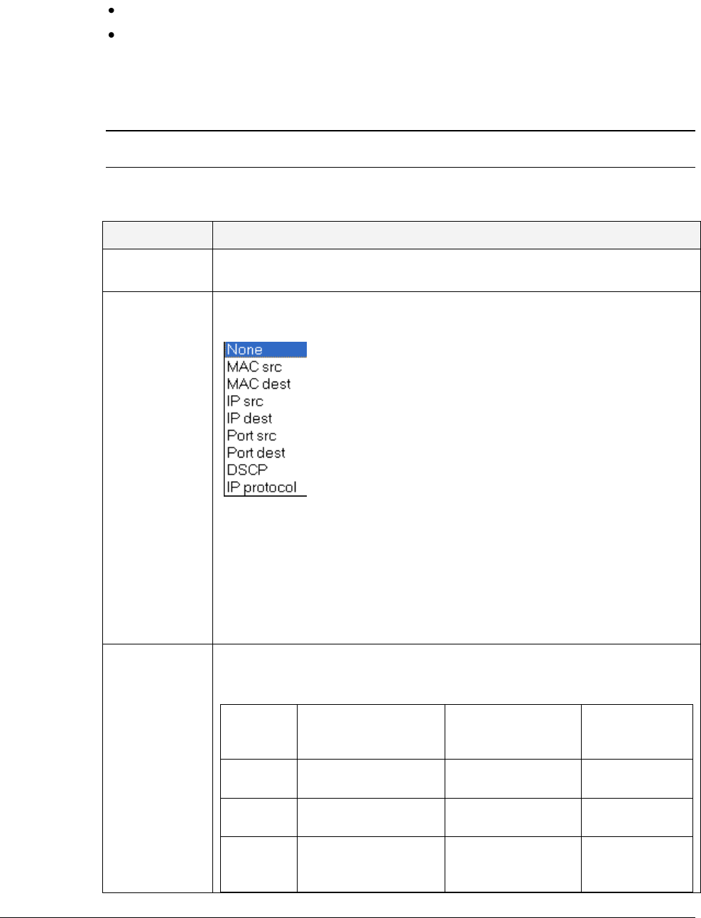
The following table provides a description of the Classifier types and values. The Type and
Values are the same for Classifier 1 and for Classifier 2.
Field
Description
Index
Read Only. Unique number, assigned by the system after applying the
changes.
Classifier Type
1/2
Type of traffic classifier.
Values:
DSCP Range Mask (DSCP field, providing differentiated services
codepoint.) The DSCP is actually the first six-bits of the TOS (Type of
Service) byte of the IP packet header)
MAC address (Source/Destination);
IP address (Source/Destination);
Port Range (Source/Destination);
IP Protocol (IP header field determining the protocol (TCP/ UDP/…)
Classifier
Value 1/2
The specific traffic-classification value, in accordance to the Classifier
Type 1 field. Below are descriptions and examples of values according to
the classifier type:
For….
(Classifier
Type)
Classifier Value
Description
Classifier Value
Example
Comment
MAC
(src/dest)
MAC/Mask
11:22:33:44:55:66/48
/Mask is optional
IP address
(src/dest)
IP/Mask
192.168.1.1/32
/Mask is optional
Port
Range
(src/dest)
port range
1230-1250

© CalAmp Sentry 4G-900 pico Base Station 42 QoS Management
Field
Description
DSCP
Range
Mask
toslow:toshigh:tosmask
(range of TOS values
followed by the TOS
mask)
13:57:0x3F
3 bits:
IP precedence
bits
value: 0-7,
Indicate
datagram
importance.
Default - 0
(higher is
better).
Bits 3,4,5:
Values: D,T,R
requesting: low
delay, high
throughput, high
reliability
IP
Protocol
IP Protocol
6
6 is TCP
range:0-255
5. Reset the SS- Base Station connectivity:
Resetting the connection of a single SS (in case the SF is applied on a Registration
Base):
Click the Subscribers menu option. Choose the Subscriber Management sub-menu
and then the Registered SS.
In the displayed Registered SS Information pane select the radio button of the
requested SS and click the Deregister button.
Resetting the connection of all registered SSs (in case the SF is applied to All Users):
Click the Quick Start menu option.
In the displayed Quick Start pane click the Stop Service button, and then click the Start
Service button.
© CalAmp Sentry 4G-900 pico Base Station 43 QoS Management
5.3 QoS Assignment to Subscribers
After defining the pool of SFs (e.g. for UL A, DL A, UL B, DL B…), these SFs can be assigned to
specific SSs according to QoS requirements.
To do so, define the MAC address of the SSs in the Pre-Provisioned SS screen, and then assign
it the relevant SFs.
After assigning the SFs to a SS, Re-set the connection between the SS and the SF.
Note: Re-setting the connection between the SS and the Base Station is required when applying
any change to an SF that is allocated to that SS.
This section details the required steps for assigning the defined SFs to specific SSs.
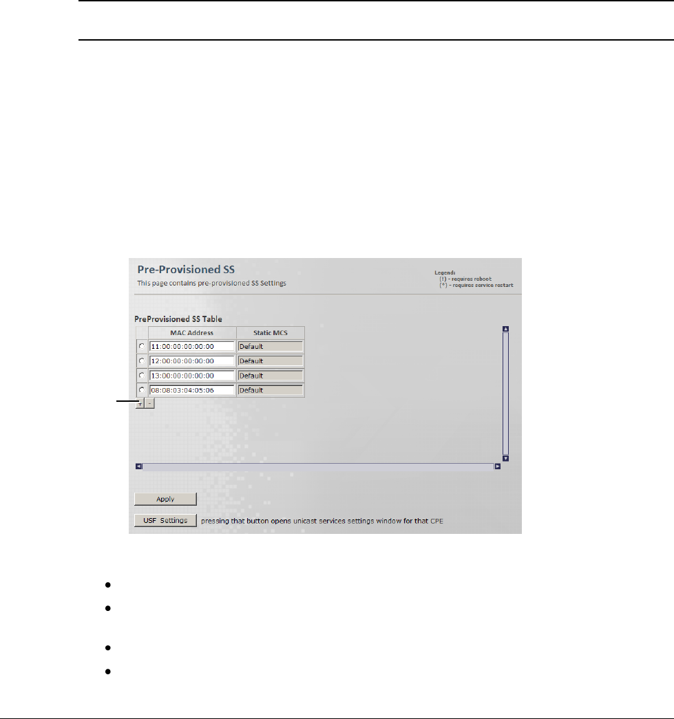
5.3.1 Assigning Service Profiles to Subscriber Stations
Subscriber Stations (SS) can be assigned a number of (pre-defined) Service Flows (SFs), where
the combined SFs serve to create the Service Profile for the SS.
To access the Pre-Provisioned SS pane
1. Click the Subscribers menu option and from the Subscriber Management sub-menu
option choose Pre-Provisioned SS. The Pre-Provisioned SS pane appears.
2. To add Subscriber Stations to the list:
Click the „+‟ sign. A row is added.
Enter the SS MAC Address. The Static MCS (CPE Specific Configuration) will be
displayed.
Click Apply.
Repeat the procedure for any additional SS to be added to the list.
Click to add an
SS MAC
address
© CalAmp Sentry 4G-900 pico Base Station 44 QoS Management
(To Remove the last row click the „–„ sign. To remove a selected row, mark that row and
click the „–„ sign.
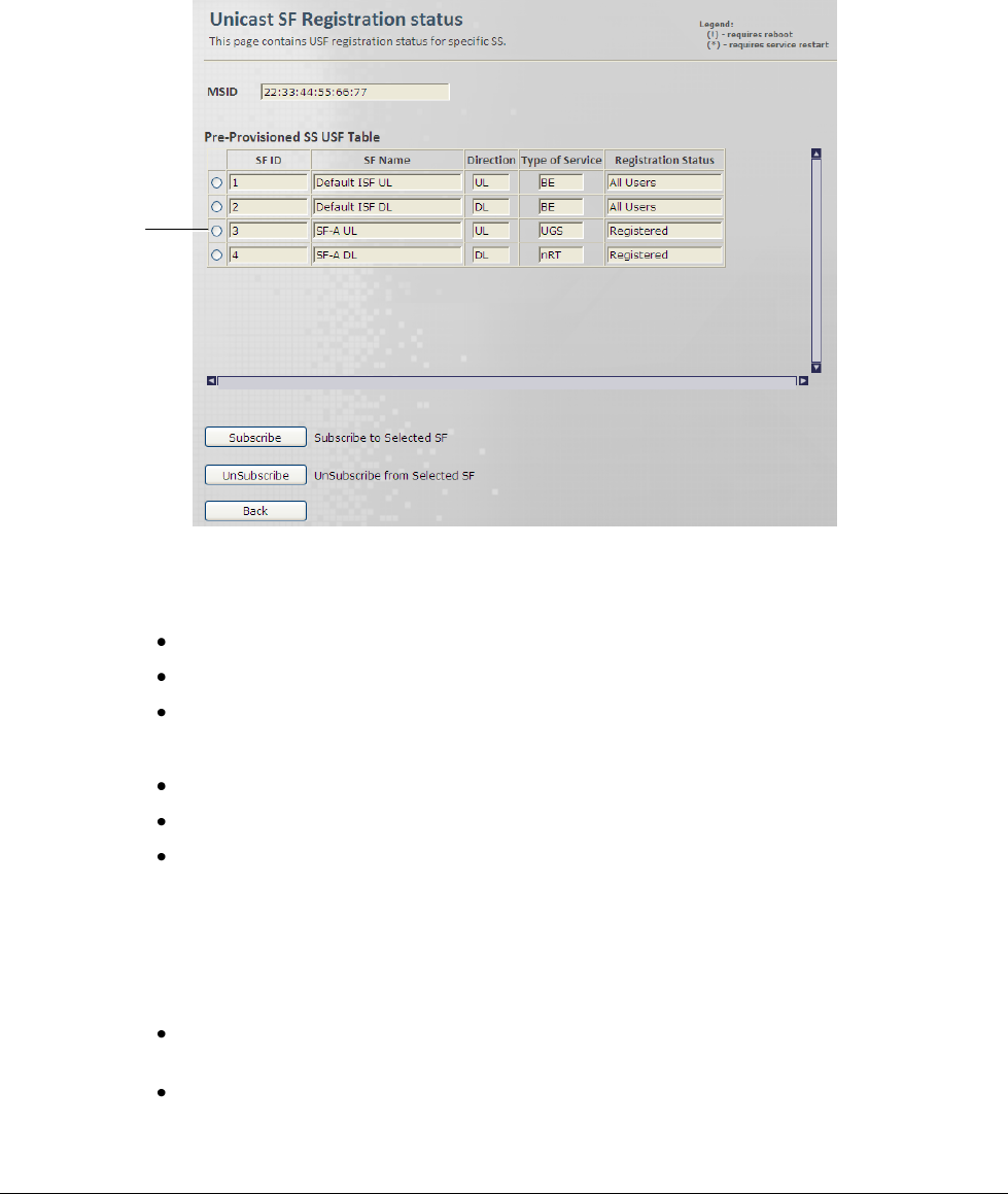
3. To assign a service profile to an SS in the list:
Check the radio-button for the first SS to be assigned QoS and click the USF Settings
operation button. The following screen appears.
The screen provides the following interfaces:
MAC address of the selected SS
List of the available Service Flows
Operation buttons for assigning and disassociating service flows from a SS
The following operation buttons are available:
Subscribe – used to assign the selected SF to the SS
Unsubscribe – used to disassociate the selected SF from the SS
Back – go back to the Pre-Provisioned SS screen (to choose another SS).
4. Select an SF row, and click the Subscribe button. The SF is assigned to the SS.
5. Reset the SS- Base Station connectivity:
Resetting the connection of a single SS (in case the SF is applied on a Registration
Base):
Click the Subscribers menu option. Choose the Subscriber Management sub-menu
and then the Registered SS.
In the displayed Registered SS Information pane select the radio button of the
requested SS and click the Deregister button.
Select
SF
© CalAmp Sentry 4G-900 pico Base Station 45 QoS Management
Resetting the connection of all registered SSs (in case the SF is applied to All Users):
Click the Quick Start menu option.
In the displayed Quick Start pane click the Stop Service button, and then click the Start
Service button.
6. Repeat the above procedure to assign additional SFs to the SS as required.
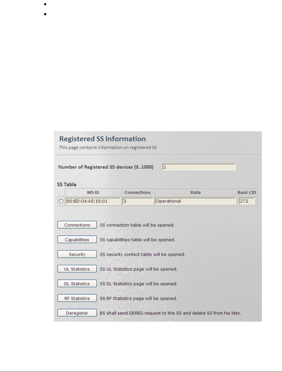
5.4 Monitoring and Maintaining Registered SSs
Connections
This pane displays a table summarizing the registered SS units basic operation information, and
provides basic maintenance operation buttons.
To access the SS Lists pane
1. Click the Subscribers menu option and then the Subscriber Management sub-menu
option. Choose Registered SS sub menu. The Registered SS Information pane is displayed.

© CalAmp Sentry 4G-900 pico Base Station 46 QoS Management
2. The following information is available:
Field
Description
Number of Registered
SS devices
Range [0,1000]
SS Table
The displayed table provides the following information for each
SS:
Field
Description
MS ID
MAC Address of SS
Connections
Number of DL & UL connections, associated
with that MSID
State
SS Operation state.
Values: init, DL Synchronization, Handover
DL acquisition, UL Acquisition, Ranging,
Handover ranging, Capabilities negotiation,
Authorization, Registration, DHCP, TOD,
TFTP, Operational, Sleep, IDLE, Aborted
Basic CID
3. Use the available buttons to perform additional operations:
Connections - SS connection hidden subtab table will be opened
Capabilities – SS Capabilities hidden subtab will be opened
Security – SS Security context hidden subtab will be opened
UL Statistics – Provides UL Statistics
DL Statistics - Provides DL Statistics
RF Statistics - Provides RF Statistics
Deregister – Reset the connection between the Base Station and the selected SS (Base
Station shall send DEREG request to the SS and delete the SS from the lists).
© CalAmp Sentry 4G-900 pico Base Station 47 Wireless (WiMAX) Parameters
6 Wireless (WiMAX) Parameters
The Wireless option includes the following sub menu options:
Networking
Radio and Frame
Security
MAC
Diagnostics
The sub-menus‟ fields and operations are described below.
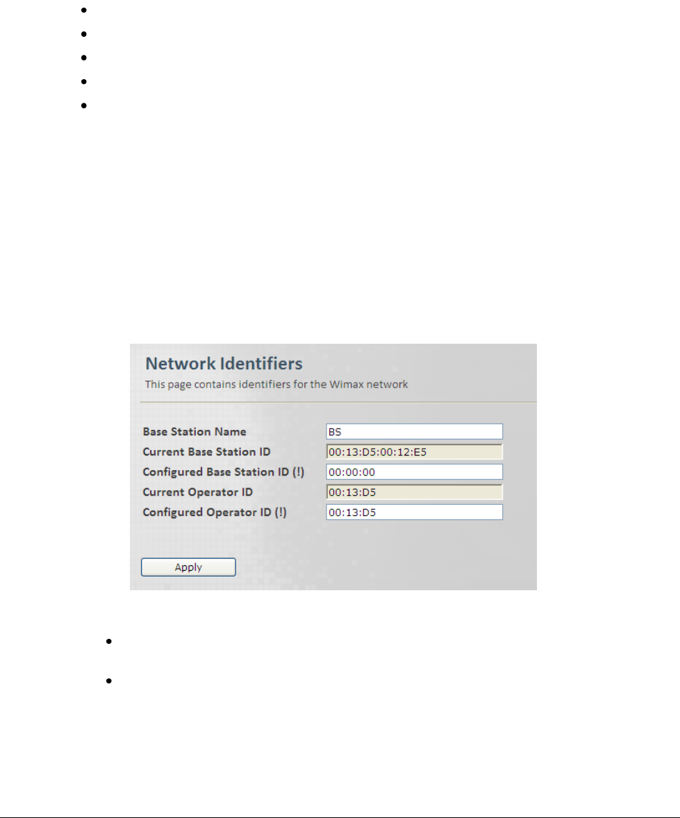
6.1 Network Identifiers
The Network Identifiers pane is used to define the Base Station name, unique ID and Network
Access Provider ID.
To access the Network Identifiers pane
1. Click the Wireless menu option and then the Wireless Admin sub-menu option. The
Network Identifiers pane is displayed.
2. Enter the Configured Base Station Unique ID, keeping the following in mind:
Current Base Station Unique ID - Last 3 octets of Base Station -ID TLV as appear in
NWG stage 3.
This ID should not be part of the MAC address, in order to allow mix of vendors.
3. Enter the Base Station Name and the Configured Operator (Network Access Provider) ID.
4. Click Apply.
© CalAmp Sentry 4G-900 pico Base Station 48 Wireless (WiMAX) Parameters
6.2 Radio and Frame
Radio and Frame configurations and capabilities.
Radio configurable parameters should be set within the valid range of values. This range is
determined by the specific country regulations, and in accordance to the device capabilities.
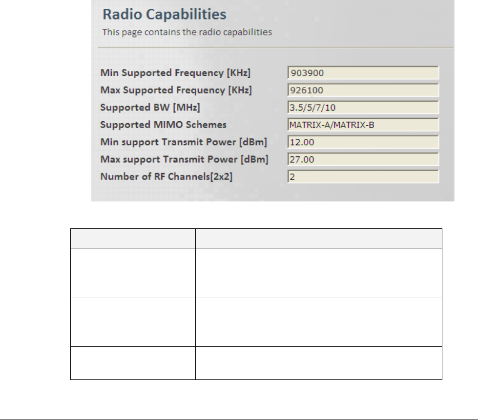
6.2.1 Radio Capabilities read Only
This pane displays the Device HW Radio configurations and capabilities.
To access the Radio Capabilities pane
1. Click the Wireless menu option and then the Radio and Frame sub-menu option. From the
Radio and Frame sub-menus choose Radio Capabilities. The Radio Capabilities pane is
displayed.
2. The Pane displays information as follows:
Field
Description
Min / Max Supported
Frequency [KHz]
Min / Max supported frequency range.
Values: Min to Max, Separated by a comma.
Example: 1350,1450
Supported BW [KHz]
Supported bandwidths in KHz.
Values are separated by commas.
Example: 5000,7000,10000
Supported MIMO
Schemes
Supported MIMO schemes.
Values: Matrixes separated with comma: A,B
© CalAmp Sentry 4G-900 pico Base Station 49 Wireless (WiMAX) Parameters
Field
Description
Min / Max support
Transmit Power [dBm]
Min / Max support Transmit Power [dbm].
Values: Min and Max separated by comma.
Example: 10,36
Number of RF
Channels[2x2]
Number of RF TX Channels
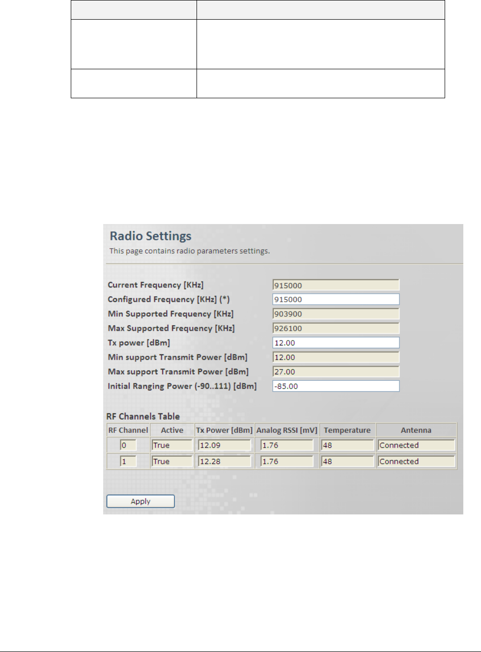
6.2.2 Radio Settings
This pane provides Radio parameters settings.
To access the Radio Settings pane
1. Click the Wireless menu option and then the Radio and Frame sub-menu option. From the
Radio and Frame sub-menus choose Radio. The Radio Settings pane is displayed.

© CalAmp Sentry 4G-900 pico Base Station 50 Wireless (WiMAX) Parameters
2. Update the required parameters in the Pane according to the following descriptions and click
Apply.
Field
Description
Frequency [KHz]
Current / Configured Frequency.
This value will be in use after the next reboot or configuration
flashing.
Values: must be within the range of allowed frequencies (i.e.
between the Min Supported Frequency and Max Supported
Frequency fields – see below)
Min / Max Supported
Frequency [KHz]
Min / Max frequency supported by the Base Station (read-only).
Values: Min to Max separated by a comma.
Example: 1350,1450
Tx power [dBm]
Tx Transmit Power Setting. Configured Tx power should be in the
valid range, as determined by the regulations and the device
capabilities (i.e. Min Supported Transmit Power and Max
Supported Transmit Power fields, see below).
Min / Max support
Transmit Power [dBm]
Min / Max supported transmission power by the Base Station
(read-only).
Values: Min and Max separated by a comma.
Example: 10,36
Initial Ranging Power
[dBm]
Maximum Initial Ranging Power. (Look for WiMAX def). If received
power exceeds the maximum Initial ranging power, signal will not
be accepted. Limits signal levels of third party equipment – used to
minimize possible interference.
Values: [-90,111]
RF Channel
RF Unit Name or ID.
Values: [0,1]
Active
This Parameter sets\shows the Transmission Activation Status of
the Base Station .
Values:
False - disabled
True - enabled
Tx Power
RF unit Transmit Power (Tx) [dBm].
Values: [-50,100]
Analog RSSI
Analog RSSI level [dBm].
Temperature
RF2 Temperature [Celsius].
Antenna
Antenna Connectivity Status.
Values: [Connected, Disconnected]
© CalAmp Sentry 4G-900 pico Base Station 51 Wireless (WiMAX) Parameters
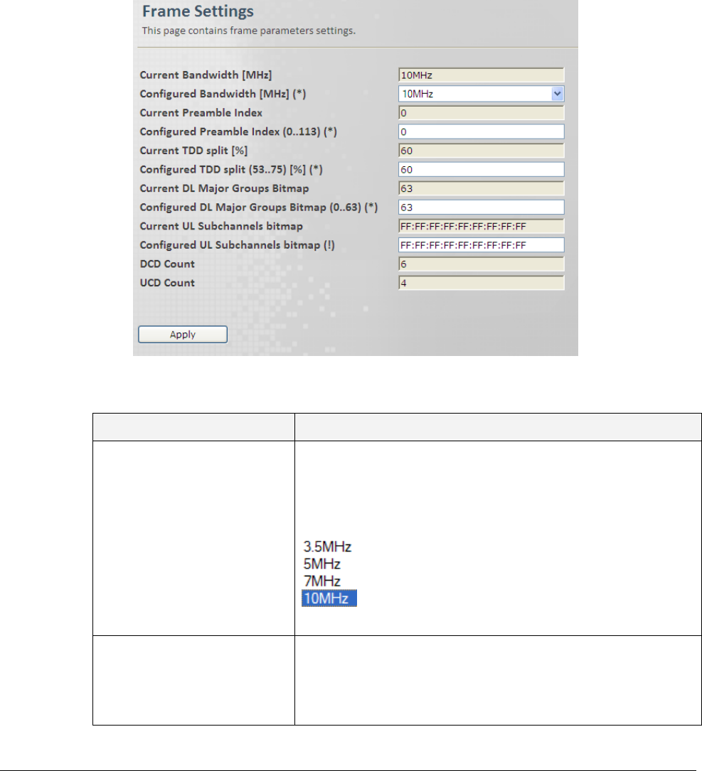
6.2.3 Frame
This pane provides Frame parameters settings.
To access the Frame pane
1. Click the Wireless menu option and then the Radio and Frame sub-menu option. From the
Radio and Frame sub-menus choose Frame. The Frame Settings pane is displayed.
2. Update the required parameters in the Pane according to the following descriptions and click
Apply.
Field
Description
Bandwidth [MHz]
Configured Bandwidth.
This value will be in use in the next service.
Configured BW must be one of the supported BWs.
Values:
Default: 10
Preamble Index
Configured Frame Preamble Index:
Preamble Index allows the SS to perform frequency and time
synchronization.
The value should be different for neighboring Base Station.

© CalAmp Sentry 4G-900 pico Base Station 52 Wireless (WiMAX) Parameters
Field
Description
Values: [0,113]
Default: 0
TDD Split [%]
Current / Configured DL frame resources [%]: Ratio (in
percentage) between DL and UL.
Values: [53,75]
Default: 66
DL Major Groups Bitmap
(0..63)
Each bit 1-6 represents one Major or Minor group of DL
resources (1-6 correspondingly). Note at least one major
group shall be selected.
Values: [0,63]
Default: 63
UL Subchannels Bitmap
UL Sub-channels Bitmap
DCD Count
Downlink Channel Descriptor Count.
UCD Count
Uplink Channel Descriptor Count.
© CalAmp Sentry 4G-900 pico Base Station 53 Wireless (WiMAX) Parameters
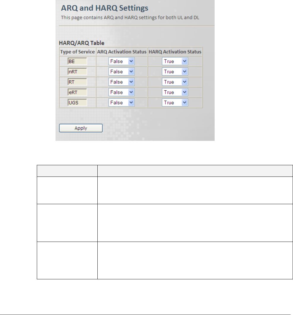
6.2.4 ARQ and HARQ
This pane provides HARQ and ARQ parameters settings for UL and DL.
To access the ARQ and HARQ pane
1. Click the Wireless menu option and then the Radio and Frame sub-menu option. From the
Radio and Frame sub-menus choose ARQ and HARQ. The ARQ and HARQ Settings pane
is displayed.
2. Update the required parameters in the Pane according to the following descriptions and click
Apply.
Field
Description
Type of Service
This parameter defines ARQ and HARQ per type of service when
operating in local mode.
Default: BE, nRT, RT, eRT, UGS
ARQ Activation
Status
This parameter specifies the activation status of ARQ for local mode
per type of service.
Values: [False, True]
Default: False, False, False, False, False
HARQ Activation
Status
This parameter specifies the activation status of HARQ for local mode
per type of service.
Values: [False, True]
Default: True, True, False, False, False
© CalAmp Sentry 4G-900 pico Base Station 54 Wireless (WiMAX) Parameters
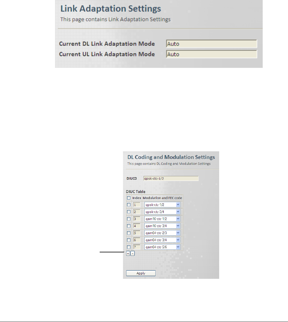
6.2.5 Link Adaptation
This is a read only pane that provides the status of the UL and DL adaptation mode.
To access the Link Adaptation pane
1. Click the Wireless menu option and then the Radio and Frame sub-menu option. From the
Radio and Frame sub-menus choose Link Adaptation. The Link Adaptation Settings pane
is displayed, showing the UL and DL adaptation mode.
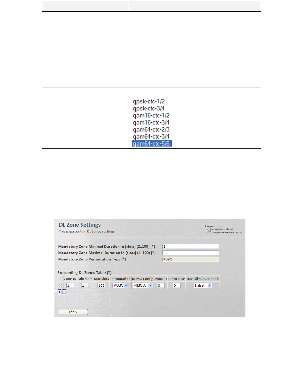
6.2.6 DL Modulation
This pane provides a table with DL Coding and Modulation settings.
To access the DL Modulation pane
1. Click the Wireless menu option and then the Radio and Frame sub-menu option. From the
Radio and Frame sub-menus choose DL Modulation. The DL Coding and Modulation
Settings pane is displayed.
2. To Add a row (max 11 rows) to the table click the „+‟ sign. To Remove the last row click the „–
‟ sign. To remove a selected row, mark the row and click the „–‟ sign.
Click to add
© CalAmp Sentry 4G-900 pico Base Station 55 Wireless (WiMAX) Parameters
3. Update the required parameters in the Pane table according to the following descriptions and
click Apply.
Field
Description
Index
DIUC Index
Table Index is for:
0 - IUC 0
1 - IUC 1
2 - IUC 2
:
12- IUC 12
Values: [0,11]
Default: 0
Modulation and FEC code
Values:
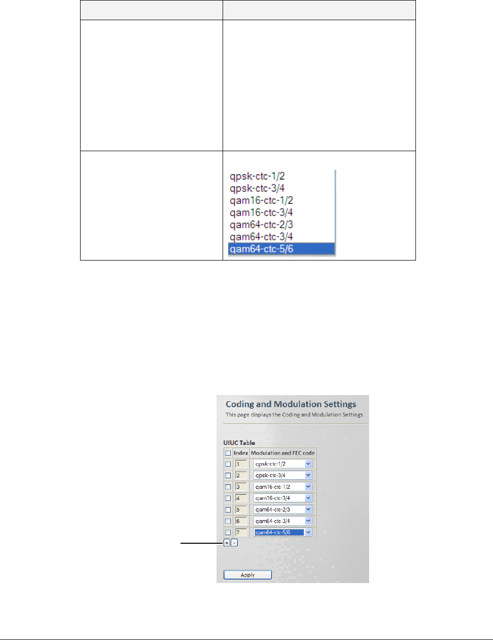
6.2.7 UL Modulation
This pane provides a table with UL Coding and Modulation settings.
To access the UL Modulation pane
1. Click the Wireless menu option and then the Radio and Frame sub-menu option. From the
Radio and Frame sub-menus choose UL Modulation. The UL Coding and Modulation
Settings pane is displayed.
2. To Add a row (max 11 rows) to the table click the „+‟ sign. To Remove the last row click the „–
‟ sign. To remove a selected row, mark the row and click the „–‟ sign.
Click to
add
© CalAmp Sentry 4G-900 pico Base Station 56 Wireless (WiMAX) Parameters
3. Update the required parameters in the Pane table according to the following descriptions and
click Apply.
Field
Description
Index
UIUC Index
Table Index is:
0- IUC 0 (FFB)
1- IUC 1
2- IUC 2
:
10- IUC 10
Values: [0,11]
Default: 0
Modulation and FEC code
Values:
6.2.8 DL Zones
This pane provides DL Zone settings.
To access the DL Zones pane
1. Click the Wireless menu option and then the Radio and Frame sub-menu option. From the
Radio and Frame sub-menus choose DL Zones. The DL Zone Settings pane is displayed.
2. To Add a row to the table click the ‘+’ sign. To Remove the last row click the ‘–’ sign. To
remove a selected row, mark the row and click the ‘–’ sign.
3. Update the required parameters in the Pane table according to the following descriptions and
click Apply.
Click to
add

© CalAmp Sentry 4G-900 pico Base Station 57 Wireless (WiMAX) Parameters
Field
Description
Mandatory Zone
Minimal Duration in
[slots]
Minimal Zone Duration in [slots].
Must not exceeds DL/UL ratio.
Values: [4,100]
Default: 4
Mandatory Zone
Maximal Duration in
[slots]
Maximal Zone Duration in [slots]
Must be greater or equal to: Min-Number-Of-Slots-In-Time-Axis
Values: [4,100]
Default: 4
Mandatory Zone
Permutation Type
Permutation Type: a label showing the permutation type of Zone
0.
Values:
Default: PUSC
Zone ID
Zone ID
Values: [0,10]
Default: 1
Min slots
Minimal duration in slots.
Must not exceeds DL/UL ratio.
Values: [0,100]
Default: 0
Max slots
Maximal duration in slots.
Must be greater or equal to of that zone: Min-Number-Of-Slots-In-
Time-Axis.
Values: [0,100]
Default: 100
Permutation
Permutation Type (Base)
Values:
0 - PUSC
1 - FUSC
2 – AMC
Default: PUSC
MIMO Config
MIMO Configuration
Values:
Default: MIMO A
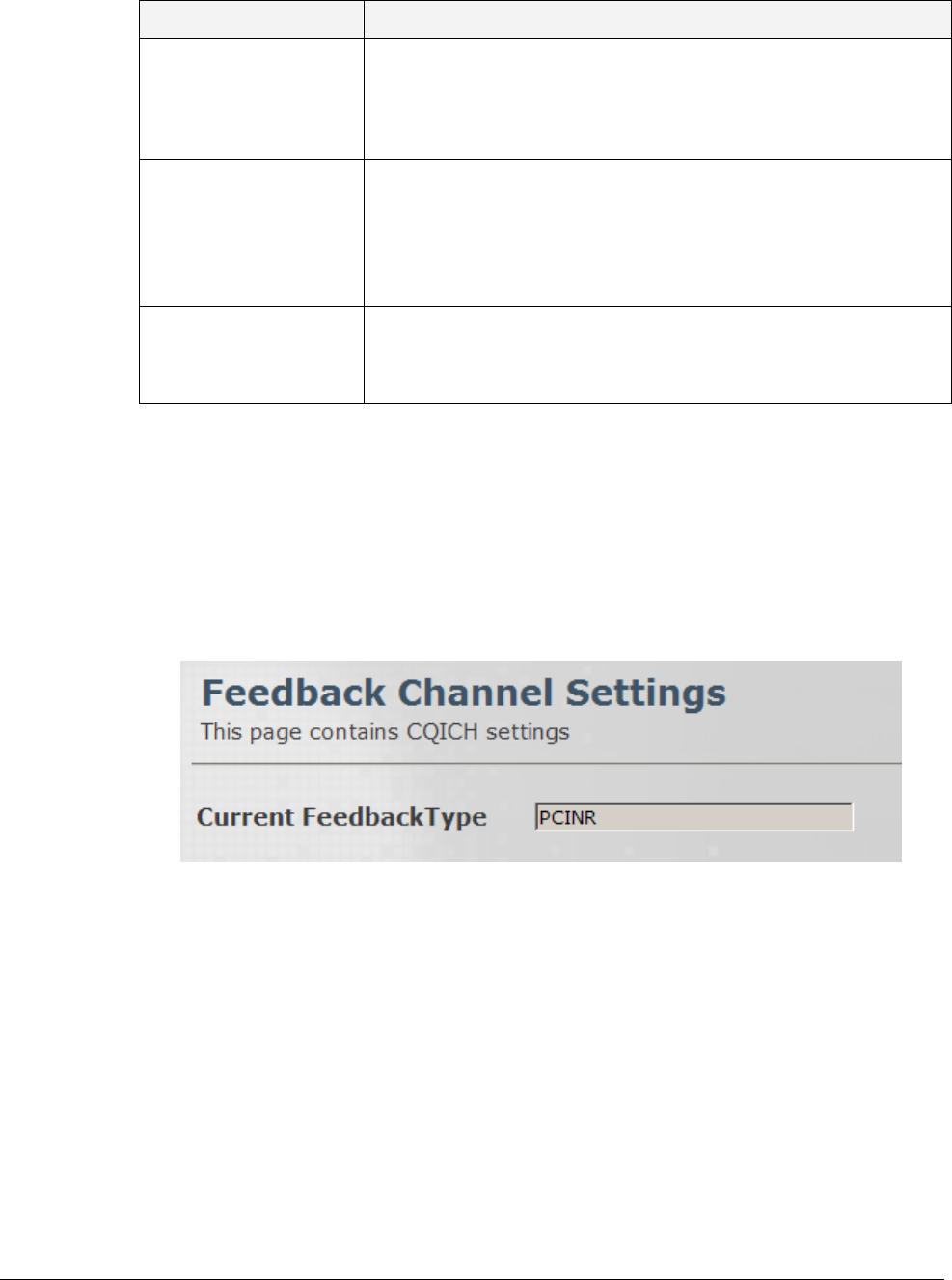
© CalAmp Sentry 4G-900 pico Base Station 58 Wireless (WiMAX) Parameters
Field
Description
PRBS ID
Pseudo random bit sequence (PRBS). Determines carrier and
pilot position.
Values: [0,2]
Default: 0
Perm Base
The permutation base (PermBase) is used together with the
WiMAX physical layer profile to compute the subcarrier-to-sub-
channel map used by a given cell.
Values: [0,31]
Default: 0
Use all Sub Channels
Use All Sub Channels (Disable sub channels rotation).
Values: True/False
Default: False
6.2.9 Feedback Channel
This pane provides CQICH setting options.
To access the Feedback Channel (CQICH) pane
Click the Wireless menu option and then the Radio and Frame sub-menu option. From the
Radio and Frame sub-menus choose Feedback Channel. The Feedback Channel Settings
pane is displayed.
The pane displays the current feedback type.
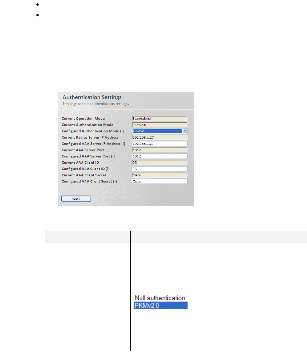
© CalAmp Sentry 4G-900 pico Base Station 59 Wireless (WiMAX) Parameters
6.3 Security - Authentication Settings
This pane provides security protocol, timers and counter settings. The pane displays relevant
parameters according to the system operation mode:
Standalone mode: requires definition of AAA server parameters
ASN-GW node: only Operation and authentication mode parameters are relevant.
6.3.1 Standalone Authentication Settings
To access the Protocol and Timers pane
1. Click the Wireless menu option and then the Wireless Security sub-menu option. From the
Wireless Security sub-menus choose Authentication. The Authentication configuration
pane is displayed.
2. Update the required parameters in the Pane according to the following descriptions and click
Apply.
Field
Description
Current Operation Mode
Specifies the operation mode, normal mode is ASNGW,
Standalone mode is designed for demos.
Values: Standalone, ASN-GW
Authentication Mode
A string specifying the authentication mode.
Values:
Default: PKMv2.0
(Null when Current-Operation-Mode is standalone)
Current Radius Server IP
Address
Current Radius Server IP Address
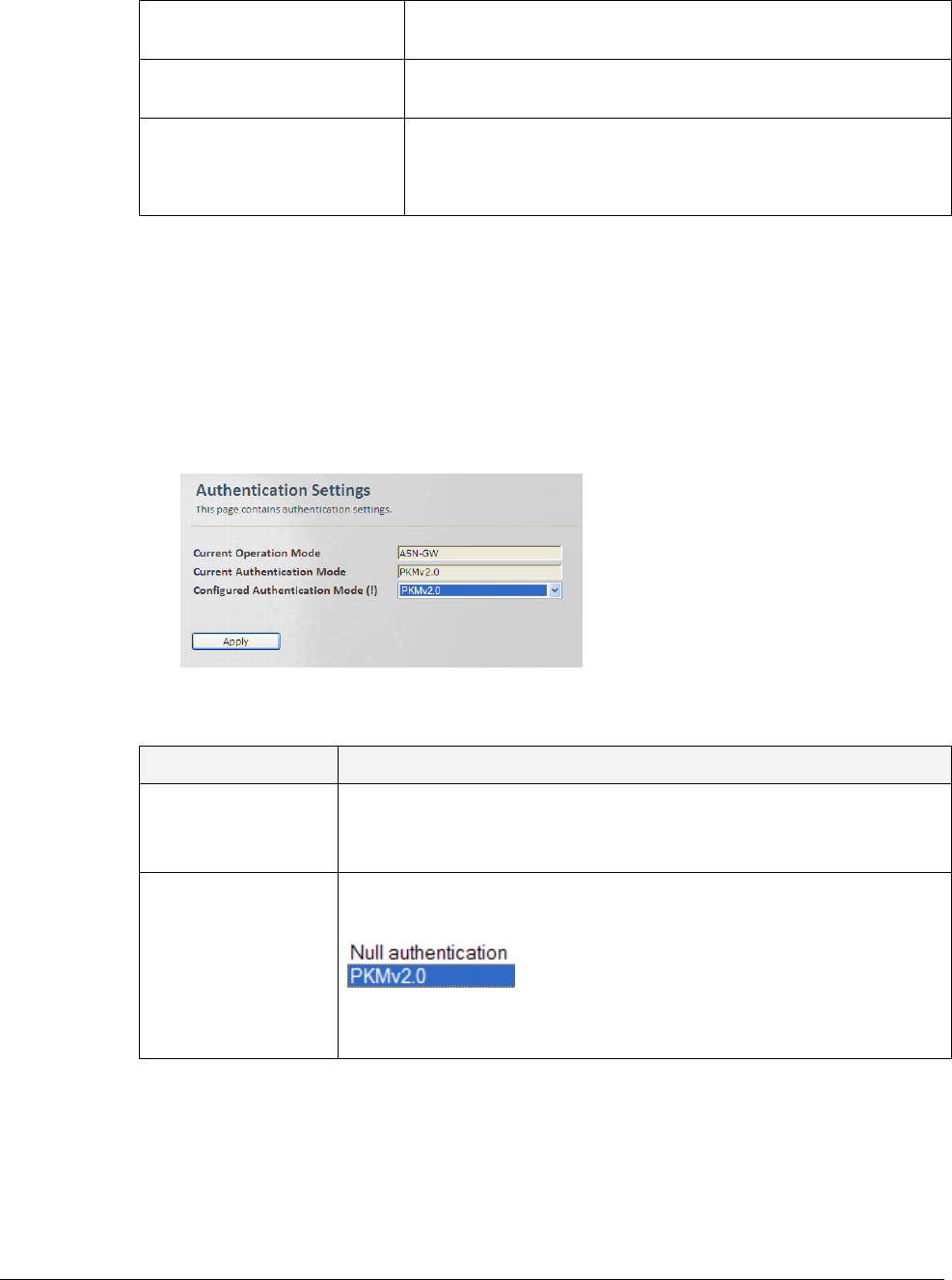
© CalAmp Sentry 4G-900 pico Base Station 60 Wireless (WiMAX) Parameters
Configured AAA Server IP
Address
AAA Server IP Address, Server Port, Client ID and Client
Secret (AAA User Defined password
AAA Server Port, Client ID,
Client Secret
AAA Parameters
TEK Lifetime
Traffic Encryption Key Lifetime in [sec].
Values: [1800,604800]
Default: 43200
6.3.2 ASN-GW Authentication Settings
To access the Protocol and Timers pane
1. Click the Wireless menu option and then the Wireless Security sub-menu option. From the
Wireless Security sub-menus choose Authentication. The Authentication configuration
pane is displayed.
2. Update the required parameters in the Pane according to the following descriptions and click
Apply.
Field
Description
Current Operation
Mode
Specifies the operation mode, normal mode is ASNGW, Standalone
mode is designed for demos.
Values: Standalone, ASN-GW
Authentication Mode
A string specifying the authentication mode.
Values:
Default: PKMv2.0
(Null when Current-Operation-Mode is standalone)
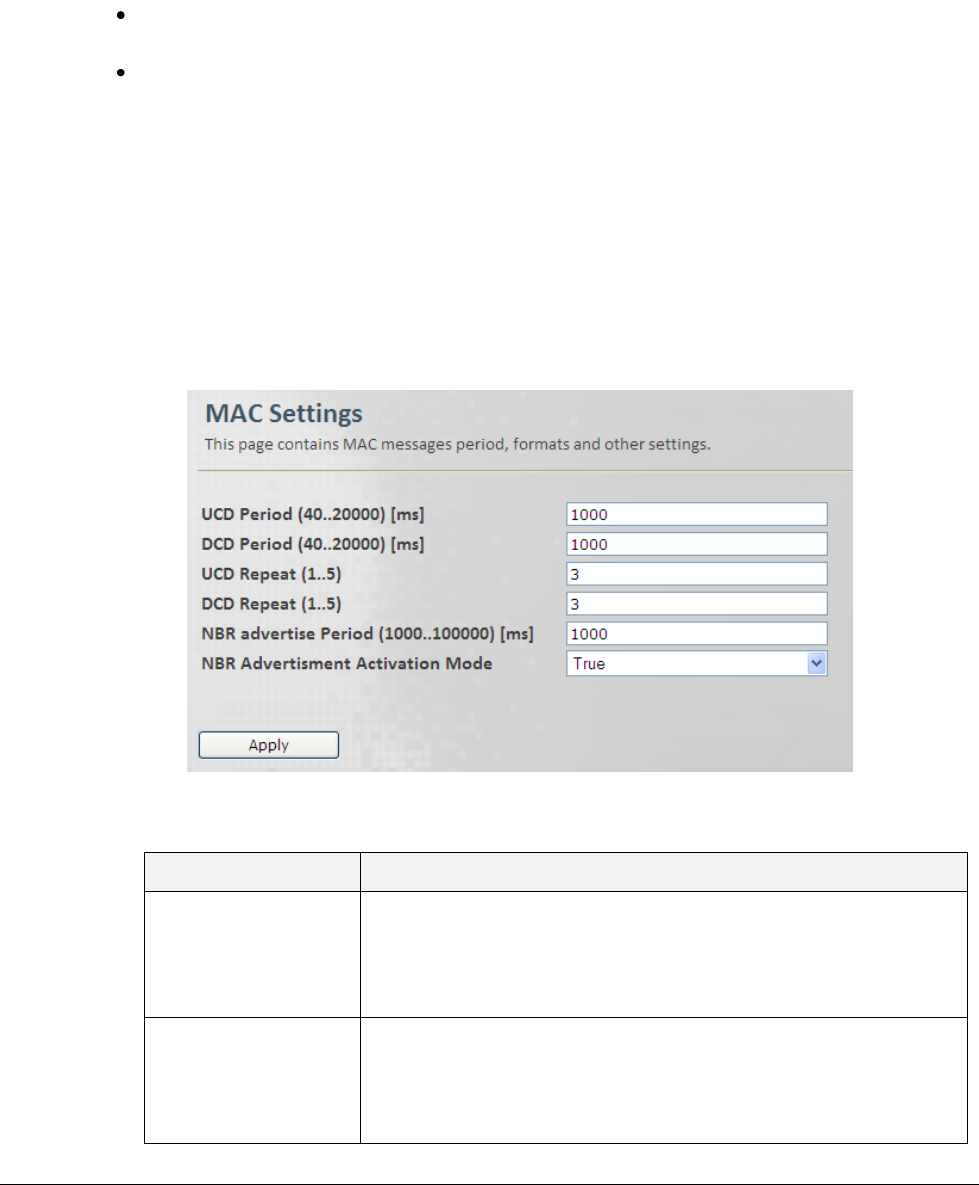
© CalAmp Sentry 4G-900 pico Base Station 61 Wireless (WiMAX) Parameters
6.4 MAC
The MAC configurations menus are displayed according to the Base Station operation mode:
Standalone mode – A single pane is available, providing the UCD/DCD time interval and the
UCD/DCD number of notifications.
ASN-GW mode – three panes are available, describing the MAC settings, Neighbor Base
Stations and DCD triggers.
The following sections describe the ASN-GW mode MAC screens.
6.4.1 General Info – MAC Settings
This pane provides general MAC settings such as MAC messages time intervals, formats, etc.
To access the General Info – MAC Settings pane
1. Click the Wireless menu option and then the MAC sub-menu option. From the MAC sub-
menus choose General Info. The General Info MAC Settings pane is displayed.
2. Update the required parameters in the Pane according to the following descriptions and click
Apply.
Field
Description
UCD Period
Defines the time interval (in [ms]), after which the UCD appears
(e.g. every 100 ms).
Values: [5,20000]
Default: 1000
DCD Period
Defines the time interval(in [ms]) after which the DCD appears
(e.g. every 100 ms).
Values: [5,20000]
Default: 1000
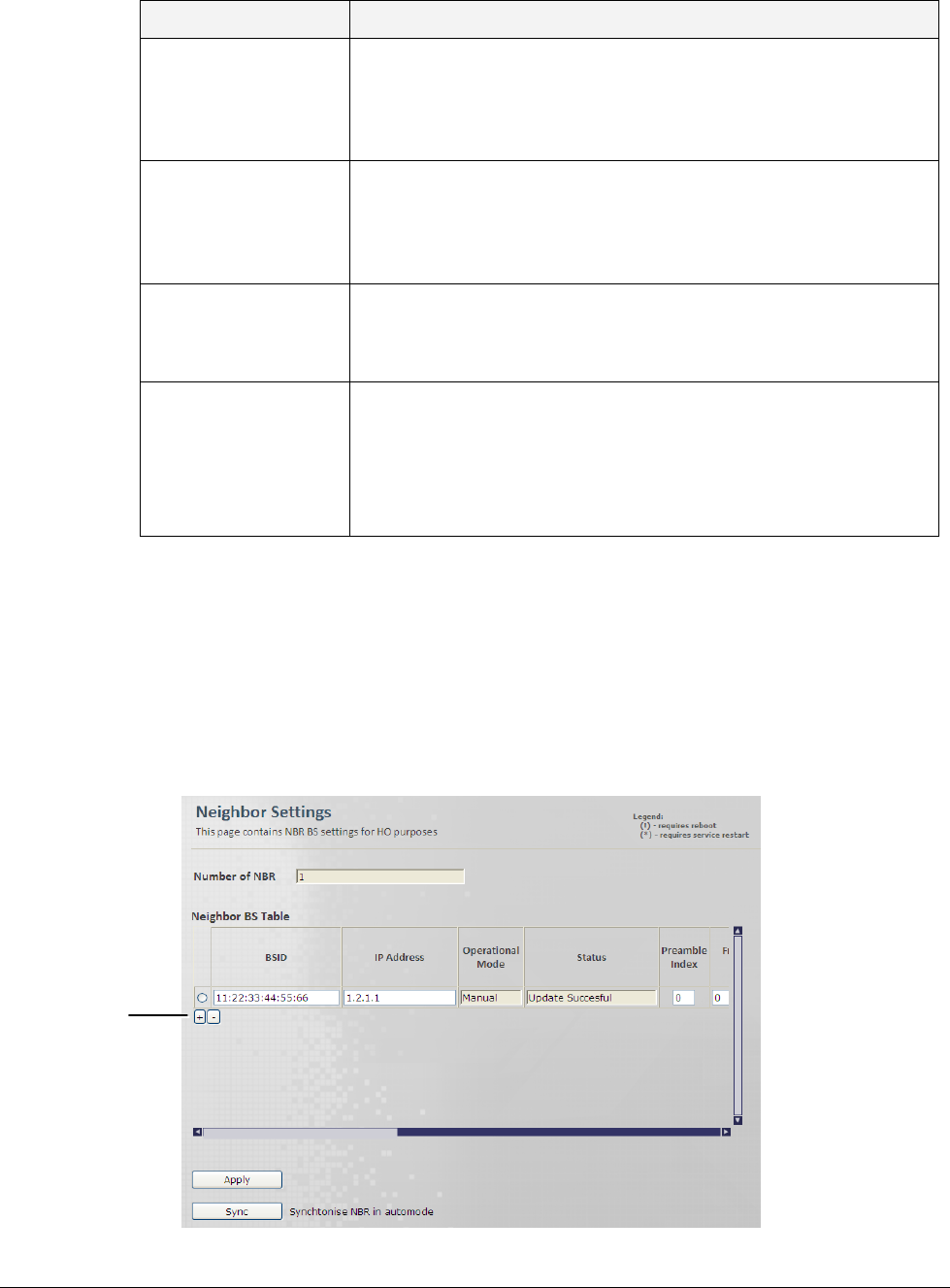
© CalAmp Sentry 4G-900 pico Base Station 62 Wireless (WiMAX) Parameters
Field
Description
UCD Repeat
Number of UCD message notifications before new message
appears.
Values: [1,5]
Default: 3
DCD Repeat
Number of DCD message notifications before new message
appears.
Values: [1,5]
Default: 3
NBR advertise Period
Period in frames to advertise neighboring Base Station.
Values: [1000,100000]
Default: 1000
NBR Advertisement
Activation Mode
Enable/Disable Base Station advertisement of NSP in NBR TLV
message broadcasting.
Values:
False - disable, True – enable
Default: True
6.4.2 Neighbor Base Station
This pane provides a table of the Neighbor Base Station‟s details – used for handover.
To access the Neighbor Base Station Settings pane
1. Click the Wireless menu option and then the MAC sub-menu option. From the MAC sub-
menus choose Neighbor Base Station. The Neighbor Base Station Settings pane is
displayed.
Click to
add
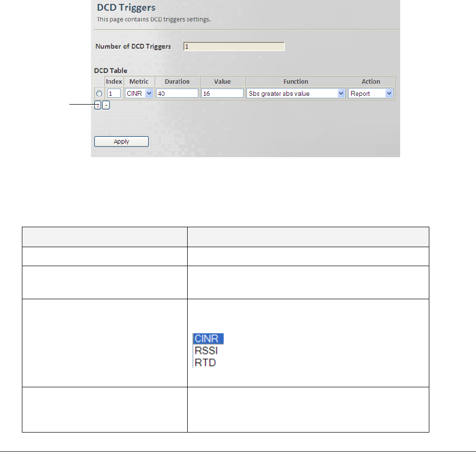
© CalAmp Sentry 4G-900 pico Base Station 63 Wireless (WiMAX) Parameters
2. To Add a row to the table click the „+‟ sign. To Remove the last row click the „–‟ sign. To
remove a selected row, mark the row and click the „–‟ sign.
3. Update the required parameters in the Pane table and click Apply.
The table provides neighboring Base Stations attributes.
6.4.3 DCD Triggers
This pane provides a table of the DCD Trigger Settings. Timing for handover triggers. Look for
neighbors in order to perform handover……
To access the DCD Triggers Settings pane
1. Click the Wireless menu option and then the MAC sub-menu option. From the MAC sub-
menus choose DCD Triggers. The DCD Triggers Settings pane is displayed.
2. To Add a row to the table click the “+” sign. To Remove the last row click the “–“ sign. To
remove a selected row, mark the row and click the “–“ sign.
3. Update the required parameters in the Pane table according to the following descriptions and
click Apply.
Field
Description
Number of DCD Triggers
Number of configured DCD triggers
Index
DCD Trigger Index.
Default: 0
Metric
This parameter specifies the DCD metric.
Values:
Default: CINR
Duration
This parameter specifies the average interval in
frames duration.
Values: [1,100]
Click to
add
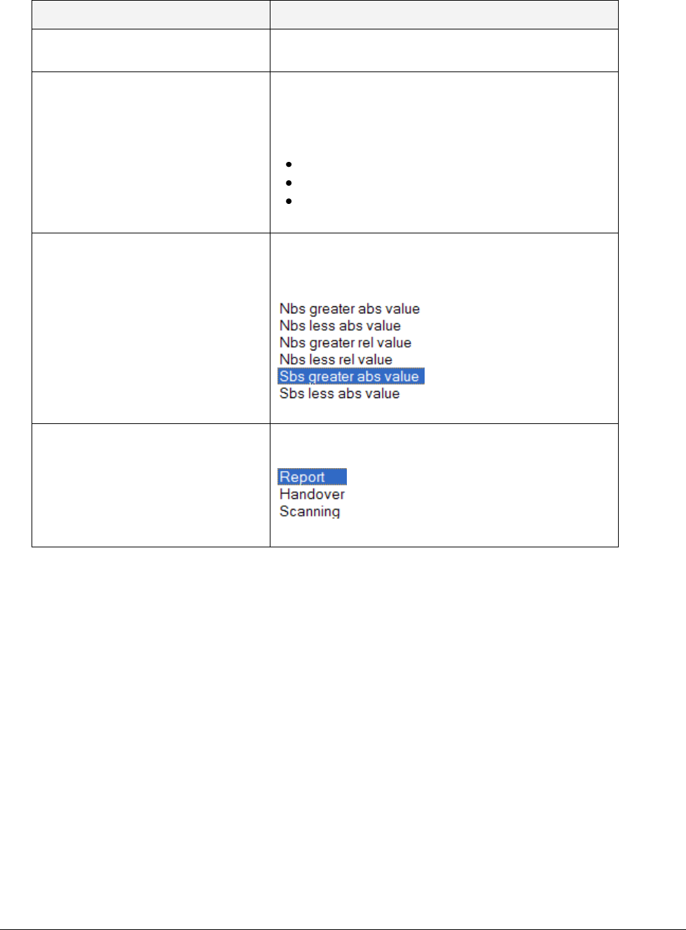
© CalAmp Sentry 4G-900 pico Base Station 64 Wireless (WiMAX) Parameters
Field
Description
Default: 40
Value [1/4, 1/2 , 1/F dB]
Trigger value is the value used in comparing
measured metric.
The value quota measurement depends on the
trigger type (metric) as follows:
For RSSI – [1/4dB]
For CINR – [1/2 dB]
For RTD – [1/Fs] (frequency sample)
Default: 16
Function
This parameter specifies the function used for the
metric.
Values:
Default: Sbs greater abs value
Action
Action performed upon reaching trigger condition.
Values:
Default: Report
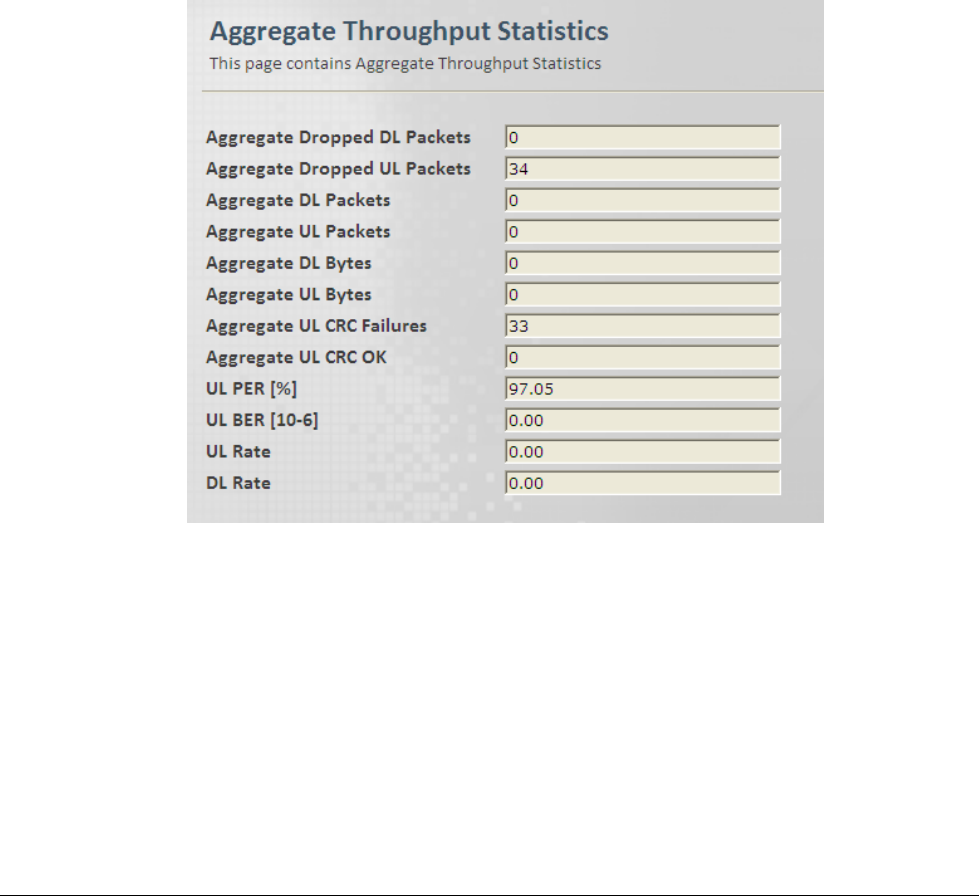
© CalAmp Sentry 4G-900 pico Base Station 65 Wireless (WiMAX) Parameters
6.5 Diagnostics
Information regarding the throughput values.
6.5.1 Aggregate Throughput
This pane provides read only aggregated Throughput Values (i.e. Dropped Packets, CRC
failures, etc.).
To access the Aggregate Throughput pane
1. Click the Wireless menu option and then the Diagnostics sub-menu option. From the
Diagnostics sub-menus choose Aggregate Throughput. The Aggregated Throughput
Values pane is displayed.

© CalAmp Sentry 4G-900 pico Base Station 66 Wireless (WiMAX) Parameters
2. The parameters displayed in the Pane are according to the following descriptions:
Field
Description
Aggregated Dropped DL / UL
Packets
Total number of aggregated Dropped DL / UL
Packets since last reset.
Aggregated DL / UL Packets
Total number of Aggregated DL / UL Packets
since last reset.
Aggregated DL / UL Bytes
Total number of Aggregated DL / UL Bytes
since last reset.
Aggregated UL CRC Failures
Total number of Aggregated UL CRC Failures
since last reset.
Aggregated UL CRC OK
Total number of Aggregated UL CRC OK since
last reset.
UL PER [%]
UL Packet Error Rate
UL BER [10-6]
UL Bit Error Rate
UL / DL Rate
UL / DL Rate

© CalAmp Sentry 4G-900 pico Base Station 67 List of Acronyms
7 List of Acronyms
Term
Description
AAA
Authentication Authorization Accounting
AES
Advanced Encryption Standard
AMC
Adaptive Modulation and Coding
API
Application Programming Interface
ASN
Access Service Network
ASP
Application Service Provider
ATPC
Automatic Transmit Power Control
BE
Best Effort
BPSK
Binary Phase Shift Keying
BS
Base Station
BWA
Broadband Wireless Access
cBS
Compact Base Station
CPE
Customer Premise Equipment
DHCP
Dynamic Host Configuration Protocol
DNS
Domain Name System
EAP
Extensible Authentication Protocol
ErtPS
Extended Real-Time Polling Service
FFT
Fast Fourier Transfer
FTP
File Transfer Protocol
FUSC
Fully Used Sub-Channelization
GW
Gateway
HA
Home Agent
HTTP
Hypertext Transport Protocol
ICMP
Internet Control Message Protocol
IDU
Indoor Units
IEEE
Institute of Electronic and Eclectic Engineers
IGMP
Internet Group Multicast Protocol
IMS
IP Multimedia System
IP
Internet Protocol
IPSec
IP Security
LAN
Local Area Network
LOS
Line-of-sight
MAC
Media Access Control

© CalAmp Sentry 4G-900 pico Base Station 68 List of Acronyms
Term
Description
MAI
Multiple Access Interference
MAN
Metropolitan Area Network
MGCP
Media Gateway Control Protocol
MIMO
Multiple-Input, Multiple-Output
MIP
Mobile IP
MSG
Multi-Service Gateways
NAP
Network Access Provider
NMS
Network Management System
NLOS
Non-line-of-sight
nrtPS
Non-Real Time Polling Service
NSP
Network Service Provider
OAM
Operations and Maintenance
ODU
Outdoor Units
OFDM
Orthogonal Frequency Division Multiplexing
OFDMA
Orthogonal frequency division multiple access
pBS
Pico Base Station
PDA
Personal Digital Assistant
PMIP
Proxy Media IP
POP
Point of Presence
PPTP
Point-to-Point Tunneling Protocol
PUSC
Partially used sub-channelization
QAM
Quadrature Amplitude Modulation
QoS
Quality of Service
QPSK
Quadrature Phase Shift Keying
RF
Radio Frequency
rtPS
Real-Time Polling Service
SF
Service Flow
SIP
Session Initiation Protocol
SLA
Service Level Agreements
SNMP
Simple Network Management Protocol
SS
Subscriber Station
STC
Space-time coding
SU
Subscriber Unit
TCP
Transmission Control Protocol
TDD
Time Division Duplex
TFTP
Trivial File Transfer Protocol

© CalAmp Sentry 4G-900 pico Base Station 69 List of Acronyms
Term
Description
UDP
User Datagram Protocol
UGS
Unsolicited Grant Service
VoIP
Voice over IP
VPN
Virtual Private Network
WAN
Wide Area Network
WiMAX
Worldwide Interoperability for Microwave Access