CalAmp Wireless Networks 1409290100 900 MHz Broadband Base Station User Manual install guide
CALAMP WIRELESS NETWORKS INC. 900 MHz Broadband Base Station install guide
Contents
- 1. antenna information
- 2. operating manual
- 3. install guide
install guide

Sentry 4G-900 Pico Base Station
Installation and Setup Guide
PN: 001-9290-001
Revision 1
May 2010

II
P
Pr
re
ef
fa
ac
ce
e
M
Ma
at
te
er
ri
ia
al
l
THE SPECIFICATIONS AND INFORMATION REGARDING THE PRODUCTS IN THIS MANUAL ARE SUBJECT TO CHANGE WITHOUT
NOTICE. ALL STATEMENTS, INFORMATION, AND RECOMMENDATIONS IN THIS MANUAL ARE BELIEVED TO BE ACCURATE BUT
ARE PRESENTED WITHOUT WARRANTY OF ANY KI ND, EXPRESSED OR IMPLIED. USERS MUST TAKE FULL RESPONSIBILITY
FOR THEIR APPLICATION OF ANY PRODUCTS.
THE SOFTWARE LICENSE AND LIMITED WARRANTY FOR THE ACCOMPANYING PRODUCT ARE SET FORTH IN THE
INFORMATION PACKET SHIPPED WITH THE PRODUCT AND ARE INCORPORATED HEREIN BY THIS REFERENCE. IF YOU ARE
UNABLE TO LOCATE THE SOFTWARE LICENSE OR LIMITED WARRANTY, CONTACT YOUR CALAMP REPRESENTATIVE FOR A
COPY.
NOTWITHSTANDING ANY OTHER WARRANTY HEREIN, ALL DOCUMENT FILES AND SOFTWARE OF THESE SUPPLIERS ARE
PROVIDED “AS IS”WITH ALL FAULTS. CALAMP AND ITS SUPPLIERS DISCLAIM ALL WARRANTIES,EXPRESSED OR IMPLIED,
INCLUDING,WITHOUT LIMITATION, THOSE OF MERCHANTABILITY, FITNESS FOR A PARTICULAR PURPOSE AND
NONINFRINGEMENT OR ARISING FROM A COURSE OF DEALING, USAGE, OR TRADE PRACTICE.
IN NO EVENT SHALL CALAMP OR ITS SUPPLIERS BE LIABLE FOR ANY INDIRECT, SPECIAL, CONSEQUENTIAL, OR INCIDENTAL
DAMAGES,INCLUDING,WITHOUT LIMITATION,LOST PROFITS OR LOSS OR DAMAGE TO DATA ARISING OUT OF THE USE OR
INABILITY TO USE THIS MANUAL, EVEN IF CALAMP OR ITS SUPPLIERS HAVE BEEN ADVISED OF THE POSSIBILITY OF SUCH
DAMAGES.
COPYRIGHT ©2010 CALAMP. ALL RIGHTS RESERVED.
CALAMP AND SENTRY 4G-900™ ARE REGISTERED TRADEMARKS OF CALAMP AND/OR ITS AFFILIATES IN THE U.S.AND
CERTAIN OTHER COUNTRIES.

III
Safety Information
General
Read this User Manual and follow all operating and safety instructions.
The base station and antennas must be installed by a professional installer.
The power requirements are indicated on the product-marking label. Do not exceed the
described limits.
Equipment Installation
The equipment should be installed in accordance with the National Electrical Code (NEC),
ANSI/NFPA 70, the Canadian Electrical Code (CEC), Part 1, CSA C22.1; and when applicable, the
National Electrical Safety Code IEEE C2. And unless marked or otherwise identified, the Standard
for the Protection of Electronic Computer/Data Processing Equipment, ANSI/NFPA 75.
RF Exposure
Sentry 4G-900 Pico Base Station is compliant with the requirements set forth in CFR 47 section
1.1307, addressing RF Exposure from radio frequency devices as defined in OET Bulletin 65. The
outdoor base station should be positioned more than 0.6 feet (20 cm) from humans. Lightning
Protection
When Sentry 4G-900 Pico Base unit is installed in an outdoor location, all indoor
components (Ethernet, power supply) should be connected through a lightning protector.
The purpose of the lightning protection is to protect people and equipment located indoors from
lightning that might strike the Sentry 4G-900 Pico Base unit or its outdoor cables. Therefore, the
lightning protector device should be installed indoors, as close as possible to the point where the
cables enter the building. The lightning protector can also be installed outdoors, as long as the
cables that go from it indoors are well protected from lightning between the box and the building
entrance.
Power Cord Protection
The Sentry 4G-900 Pico Base should always be connected to the supplied data adapter for both
power supply and data transfer purposes.
Any other type of connection/application of the Sentry 4G-900 Pico Base and/or supplied data
adapter is not allowed.
Route all power supply cords so that people cannot walk on them, or place objects on or against
them. This can pinch or damage the cords.
IV
Servicing
Do not open the cover of this product and attempt service unless instructed by a CalAmp
certified technician. Refer all repairs to qualified service personnel. Removing the covers or
modifying any part of this device voids its warranty.
Keep away from electric power lines!
Carefully read and follow all instructions in this manual. By nature of the installation, you may be
exposed to hazardous environments and high voltage. Use caution when installing the outdoor
system.
Antenna Grounding Requirements
Verify that the antenna or cable system is grounded (earthed).
The antenna installation must be as per Article 810 of the NEC. Of particular note is the
requirement that the grounding conductor not be less than 10 AWG (Cu). The scheme should be
either in accordance with UL 96 and 96A. Lightning Protection Components and Installation
Requirements for Lightning Protection Systems, or tested in accordance with UL 50 and UL 497.
Outdoor Grounding System
Verify that the base station is grounded.
The system must be properly grounded to protect against power surges and accumulated static
electricity. It is the installer responsibility to install this device in accordance with the local
electrical codes.
Safety Hazards
Warning!
Installing Sentry 4G-900 Pico Base can pose a serious hazard. Be sure to take
precautions to avoid the following:
Exposure to high voltage lines during installation
Falling when working at heights or with ladders
Injuries from dropping tools
Contact with AC wiring (power system connection)
Warning!
To reduce the risk of fire, only use a No. 24AWG or larger telecommunication line cord between
the indoor and outdoor units.

V
Important Note:
This device complies with part 15 of the FCC Rules. Operation is subject to the following two
conditions: (1) This device may not cause harmful interference, and (2) this device must accept
any interference received, including interference that may cause undesired operation.
Changes or modifications not expressly approved by the party responsible for compliance could
void the user's authority to operate the equipment.
Note: This equipment has been tested and found to comply with the limits for a Class B digital
device, pursuant to part 15 of the FCC Rules. These limits are designed to provide reasonable
protection against harmful interference in a residential installation. This equipment generates,
uses and can radiate radio frequency energy and, if not installed and used in accordance with
the instructions, may cause harmful interference to radio communications. However, there is no
guarantee that interference will not occur in a particular installation. If this equipment does
cause harmful interference to radio or television reception, which can be determined by turning
the equipment off and on, the user is encouraged to try to correct the interference by one or
more of the following measures:
Reorient or relocate the receiving antenna.
Increase the separation between the equipment and receiver.
Connect the equipment into an outlet on a circuit different from that to which the
receiver is connected.
Consult the dealer or an experienced radio/TV technician for help.

About This Guide
This user guide provides essential product functionality with all the information necessary to
professionally install and configure the Sentry 4G-900 Pico Base Station.
This guide is intended for experienced technicians and operators. It is assumed that the
customers installing, operating and maintaining this product are familiar with WiMAX
technologies and procedures.
While some safety precautions are reviewed here, this manual assumes that installers have been
trained in safe installation practices. Users, who are new to WiMAX technologies and service
procedures, should not rely on this manual for comprehensive guidance.

VII
List of Acronyms
ASN
Access Service Network
CPE
Customer Premise Equipment
FTP
File Transfer Protocol
GW
Gateway
HTTP
Hypertext Transport Protocol
IDU
Indoor Units
IEEE
Institute of Electronic and Eclectic Engineers
IP
Internet Protocol
LAN
Local Area Network
LOS
Line-of-sight
NMS
Network Management System
ODU
Outdoor Units
QoS
Quality of Service
RF
Radio Frequency
SLA
Service Level Agreements
SNMP
Simple Network Management Protocol
TCP
Transmission Control Protocol
WiMAX
Worldwide Interoperability for Microwave Access

VIII
Table of Contents
Preface Material ........................................................................................................................ II
About This Guide .............................................................................................................................. VI
List of Acronyms .............................................................................................................................. VII
Table of Contents............................................................................................................................ VIII
1 Introduction ...................................................................................................................... 10
1.1 About Sentry 4G-900 Pico Base Station ....................................................................................... 10
1.1.1 Main Features and Capabilities .......................................................................................... 11
1.2 System Architecture ................................................................................................................... 11
1.3 Interfaces .................................................................................................................................. 12
1.3.1 Bottom Panel ................................................................................................................... 12
1.3.2 Top Panel ........................................................................................................................ 13
2 Site and Installation Requirements ................................................................................. 14
2.1 Pico Base Installation Location .................................................................................................... 14
2.1.1 Criteria for Outdoor Locations ........................................................................................... 14
2.1.2 Criteria for Indoor Locations .............................................................................................. 14
2.1.3 Antenna Grounding Requirements ..................................................................................... 14
3 Installation Procedure ...................................................................................................... 15
3.1 Pre-Installation Safety Instructions ............................................................................................. 15
3.2 Unpacking ................................................................................................................................. 15
3.3 Required Tools and Materials ...................................................................................................... 16
3.4 Installing the Pico Base .............................................................................................................. 16
3.4.1 Overview ......................................................................................................................... 16
3.4.2 Cover Console Port ........................................................................................................... 17
3.4.3 Assemble PoE Connector................................................................................................... 17
3.4.4 Assemble Mounting Bracket .............................................................................................. 18
3.4.5 Mount the Pico Base ......................................................................................................... 19
3.4.5.1 Wall Mount .......................................................................................................... 19
3.4.5.2 Pole Mount .......................................................................................................... 20
3.4.6 Antenna Connections ........................................................................................................ 21
3.4.6.1 RF Connections and Grounding ............................................................................. 21

IX
3.4.7 Connect the Pico Base Data Adapter .................................................................................. 22
4 Setup ................................................................................................................................. 24
4.1 Connecting Pico Base to Web Interface ....................................................................................... 24
4.2 Verifying IP Connectivity ............................................................................................................ 25
5 Troubleshooting ............................................................................................................... 26
5.1 No IP connectivity ...................................................................................................................... 26
5.2 No Serial Connection .................................................................................................................. 26
Appendix A – Specifications .................................................................................................. 27
Appendix B – IDU to ODU Cable Specifications ................................................................... 29
Appendix C – Console Connector ......................................................................................... 30
Appendix D - Mechanical Drawing ......................................................................................... 31
10
1 I
In
nt
tr
ro
od
du
uc
ct
ti
io
on
n
1.1 About Sentry 4G-900 Pico Base Station
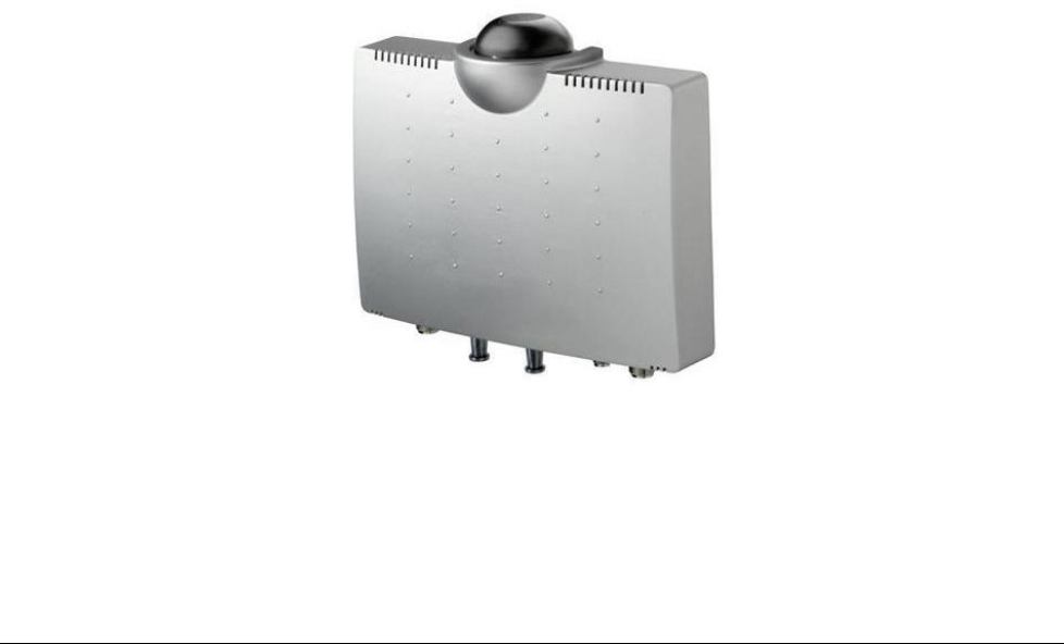
CalAmp Sentry 4G-900 Pico Base Station is a single sector station used to enhance outdoor and
indoor WiMAX coverage and capacity. The unit is easily installable, powered by PoE and supports
remote management.
Sentry 4G-900 Pico Base provides the full base station functionality necessary for serving a
single sector and operating in the 902-928 MHz ISM band. It supports up to 512 subscriber units
and its light weight and small footprint allow it to be easily mounted by one person on poles,
street lamps or walls.
The Pico Base is a broadband wireless access system based on the 802.16e mobile WiMAX
standard. Sentry 4G-900 systems are designed for robustness and simplicity, offering feature-
rich services with low deployment and operation costs, for unmatched operator competitiveness
and fast ROI.
The Pico Base provides all the functionality necessary to communicate with fixed and mobile
subscriber units according to the service criteria and customer Service Level Agreements
(SLA). The end-to-end Quality of Service (QoS) ensures the same high quality WiMAX experience
is delivered to customers outside or inside his/her home or small office.
The Pico Base is supported by CalAmp management system.
Figure 1. Sentry 4G-900 Pico Base Station
11
1.1.1 Main Features and Capabilities
All outdoor, one-box Pico Base Station solution
GPS synchronization
MIMO (2x2) support
NLOS
Small footprint and light weight enables simple installation and deployment by a single
person
IEEE802.16e Wave2 Standard Compliance
Backbone Ethernet connectivity via a 10/100 Base-T network interface
Supports fixed and mobile CPEs
Supports 3.5 MHz, 5MHz,7MHz and 10MHz channel bandwidth
Traffic classification and connection establishment initiation
Policy-based data switching
Quality of Service (QoS) management
Alarms management
An SNMP agent incorporated into the unit enables extensive In-Band (IB) management of
the Base Station and all its registered CPEs
R6 interface to ASN GW profile C
1.2 System Architecture
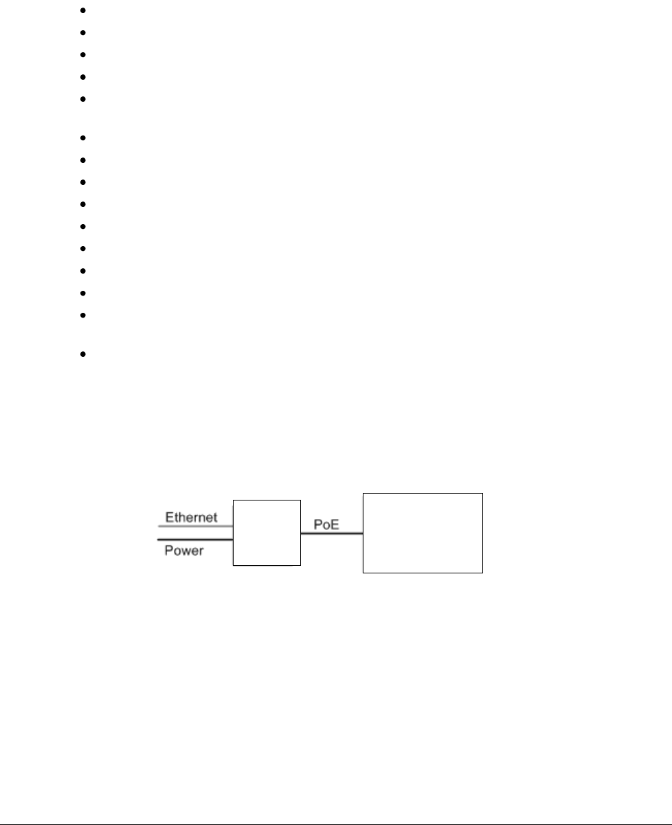
The Pico Base unit receives power and data over PoE.
Figure 2. Block Diagram
Pico Base
PoE
Device
12
1.3 Interfaces
The unit is installed vertically, where the integrated GPS antenna is located on the
top panel
(
facing the sky). All other connections, including the optional GPS external antenna connections
are located on the
bottom
panel.
1.3.1 Bottom Panel
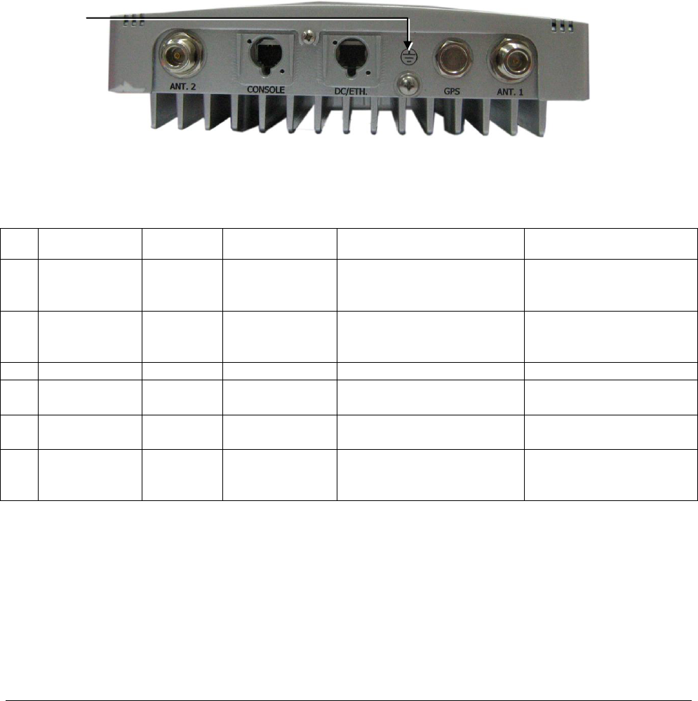
The interface panel supports the antenna, power and Ethernet connections.
Figure 3. Pico Base Interface Panel
The following table provides a description of the Pico Base bottom panel connectors and ports.
Table 1. Bottom Panel Connectors
No.
Connector
Name
Connector
Type
Cable Type
Description
Connected to
1
ANT1
N type
Female
RG 214/U
RF antenna connection
external antenna or
Screwed-on omni-
directional antenna
2
Console
RJ45
Cat5 ETH
Low level CLI for CalAmp
technical personnel. RS-
232
Computer
3
DC + ETH
RJ45
Cat5 ETH
DC 1.5A + Ethernet Cat5
PoE data adapter
4
GND
1 screw
ETSI
#10 AWG bare
copper wire
Grounding lug. #10 AWG
bare copper wire
Central earth ground,
Tower or pole chassis
5
GPS
(optional)
TNC
Female
RG-59
Base Station
Synchronization
Optional External GPS
antenna
6
ANT2
N type
Female
RG 214/U
RF antenna connection
external antenna or
Screwed-on omni-
directional antenna
GND
13
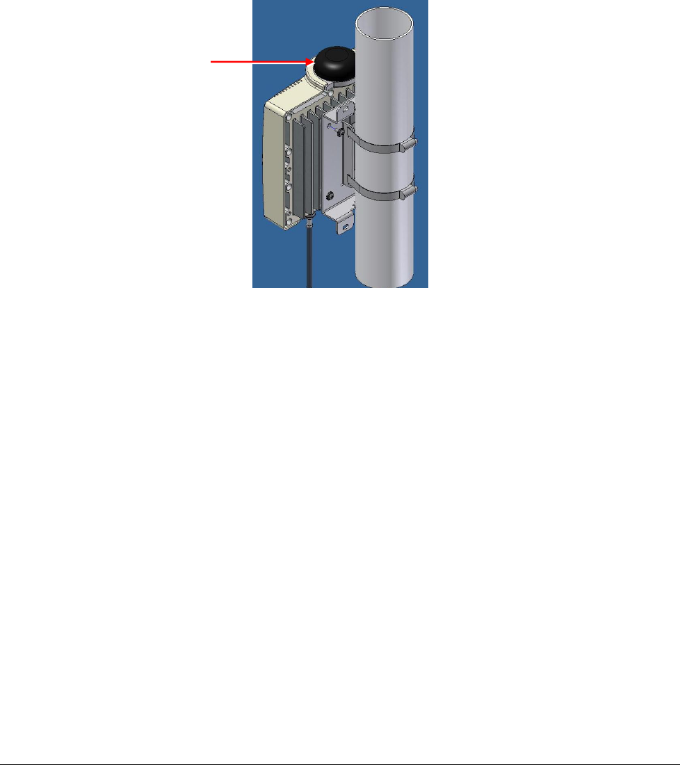
1.3.2 Top Panel
The top panel supports the built-in GPS antenna. (An external GPS antenna can be connected to
the bottom panel GPS connector). See section 0 for more information on GPS antennas and
installation criteria.
The figure below shows the Pico Base mounted on a pole.
Figure 4. Top panel GPS Antenna
Integrated GPS
antenna

14
2 S
Si
it
te
e
a
an
nd
d
I
In
ns
st
ta
al
ll
la
at
ti
io
on
n
R
Re
eq
qu
ui
ir
re
em
me
en
nt
ts
s
2.1 Pico Base Installation Location
WARNING!
THE PICO BASE UNIT MUST ALWAYS BE INSTALLED VERTICALLY AND TOP-DOWN –
WITH THE CONNECTORS ON THE UNDERSIDE FOR PROTECTION.
This section describes the criteria that should be considered when selecting the Pico Base
installation location.
2.1.1 Criteria for Outdoor Locations
Take into account your site plan and local regulations that define distance from populated areas.
The unit should be mounted in the highest possible point. Reception will increase according
to the height of the antennas.
There should be minimum obstacles between the antenna and the planned coverage area
(zone) – minimum of 55% exposure to the sky.
Take into account (according to your coverage site plan) distance from other antennas or
devices that may cause interferences.
Accessibility for maintenance (where possible).
2.1.2 Criteria for Indoor Locations
A minimum of 55% direct LOS exposure of the external GPS antenna to sky.
Maximum distance between external GPS antenna to Pico Base = 22 meters.
2.1.3 Antenna Grounding Requirements
The antenna installation must be as per Article 810 of the NEC. Of particular note is the
requirement that the grounding conductor not be less than 10 AWG (Cu). The scheme should
either correspond to UL 96 and 96A. Lightning Protection Components and Installation
Requirements for Lightning Protection Systems, or tested in according to UL 50 and UL 497.

15
3 I
In
ns
st
ta
al
ll
la
at
ti
io
on
n
P
Pr
ro
oc
ce
ed
du
ur
re
e
3.1 Pre-Installation Safety Instructions
Warning!
Before installing the Pico Base, review the following safety hazards:
Installing Pico Base can pose a serious hazard. Be sure to take precautions to avoid the
following:
Exposure to high voltage lines during installation
Falling when working at heights or with ladders
Injuries from dropping tools
Contact with AC wiring (power system connection)
3.2 Unpacking
Upon receiving the Pico Base unit, perform the following:
1. Examine the shipping container for damage before unpacking the unit.
2. Perform a visual inspection to reveal any physical damage to the equipment.
Note: In case of damage, contact the shipping company.
3. Verify that all of the equipment (listed below) is included. Otherwise contact CalAmp.
4. The Pico Base is shipped with the following equipment:
Sentry 4G-900 Pico Base Station.
Integral 2 x omni-directional antennas.
Data adapter including Power Supply.
Internal GPS receiver and integrated GPS antenna
Pico Base pole/wall mounting bracket.
Cat5 Serial cable (2m) for the console connector of the Pico Base (cable connectors:
DB9F, RJ45)
Note: The connection between the Pico Base to the data adapter is performed by a standard
outdoor Cat5E shielded Ethernet cable. The Ethernet cable is not supplied.
Metal bands x 2 for mounting on poles
Screws, springs and washers x 4

16
3.3 Required Tools and Materials
In order to install the Pico Base, a standard professional toolbox is required.
3.4 Installing the Pico Base
Note: Should be installed at highest possible point!
Important!
The equipment should be installed in compliance with the National Electrical Code (NEC),
ANSI/NFPA 70, the Canadian Electrical Code (CEC), Part 1, CSA C22.1; and when applicable, the
National Electrical Safety Code IEEE C2. Unless marked or otherwise identified, the Standard for
the Protection of Electronic Computer/Data Processing Equipment, ANSI/NFPA 75.
There are two types of installations for the Pico Base:
Wall mount - The Pico Base can be attached to any wall that can support the load of the
unit.
Pole mount - The unit can be attached to any pipe or pole with diameter 1.75” to 10".
3.4.1 Overview
The Pico Base installation procedure consists of the following steps:
1. Covering the Console port (only used for maintenance purposes by authorized personnel) –
see 3.4.2.
2. Assembling the PoE connector – see 3.4.3.
3. Assembling the Pico Base mounting bracket – see 3.4.4.
4. Mounting the Pico Base (wall/pole mount) – See 3.4.5.
5. Antenna connections and grounding – see 3.4.6.
6. Connecting the Pico Base Data Adapter – see 3.4.7.
7. See chapter 4 for the initial Setup procedure.
17
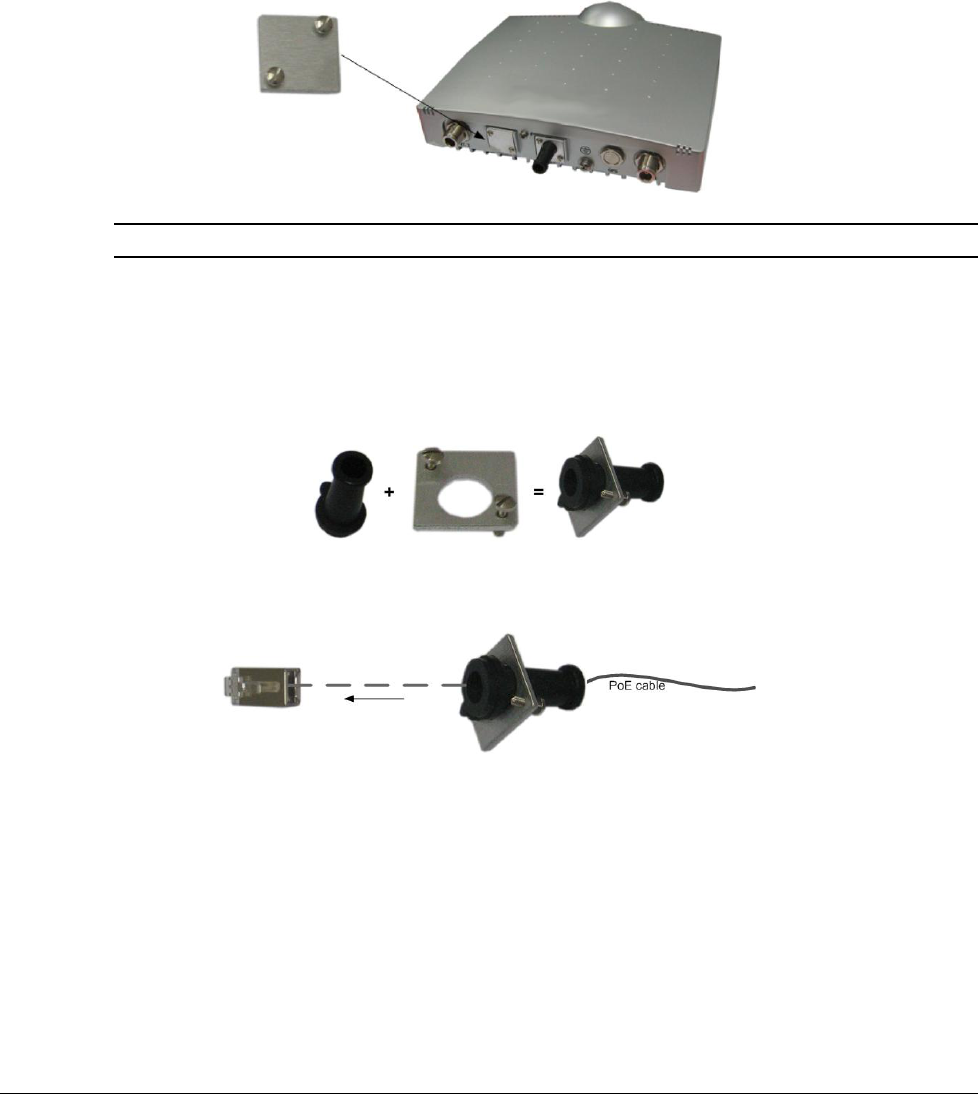
3.4.2 Cover Console Port
The Console port is only used for maintenance operations performed by authorized service
personnel and should be closed in normal conditions.
Secure the Console port with both of the (supplied) screws to the port panel. See figure below.
Note: See Appendix C – Console C for Console cable pin out.
3.4.3 Assemble PoE Connector
The DC/Ethernet connector that provides the PoE connection must be assembled as follows:
1. Insert the cap in to the DC/Ethernet port cover, with the as shown below.
2. Insert the PoE cable (not supplied) through the cap and connect it to the supplied J45
connector.
3. Snap the J45 connector into the DC/Ethernet opening.
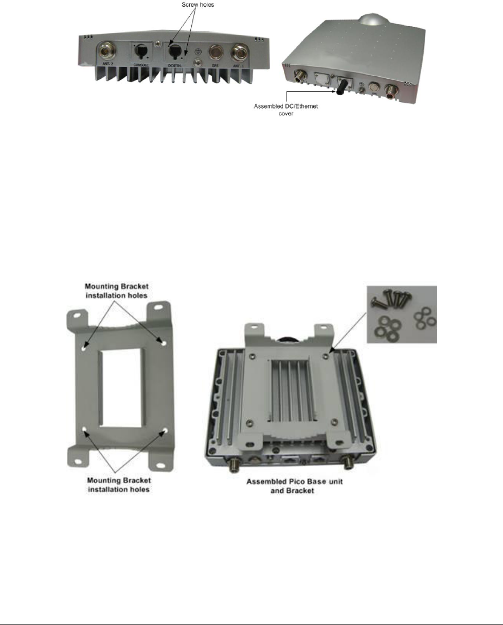
18
4. Align the cap ridge with slot in port and insert both screws into the cover screw holes and
insert in to corresponding screw holes located at the top-left and bottom-right of the
DC/Ethernet port.
5. Tighten the screws and secure cover to port.
3.4.4 Assemble Mounting Bracket
To assemble the mounting bracket on the Pico Base unit
1. Align the mounting brackets’ four inner holes with the Pico Base installation holes, located on
the under-side of the unit (rib-side). See figure below.
2. Using a Phillips screwdriver, secure the bracket to the Pico Base unit with the four screws
and washers (supplied).
19
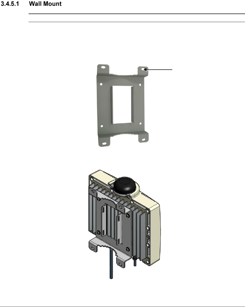
3.4.5 Mount the Pico Base
Note: The Pico Base can be attached to any wall that can support the load of the unit.
To mount the unit on the wall
1. Determine the location of the Pico Base mounting bracket and mark the drilling holes on the
wall surface based on the brackets’ four (outer) mounting holes (two at the top and two at
the bottom).
PLAN THE INSTALLATION SO THE INTERFACES FACE DOWN- PROVIDING MORE
PROTECTION AGAINST THE ELEMENTS.
2. Drill the four holes in the wall and align the bracket installation holes with the holes in the
wall. Secure with the appropriate screws and washers (not supplied).
Mounting holes x 4
20
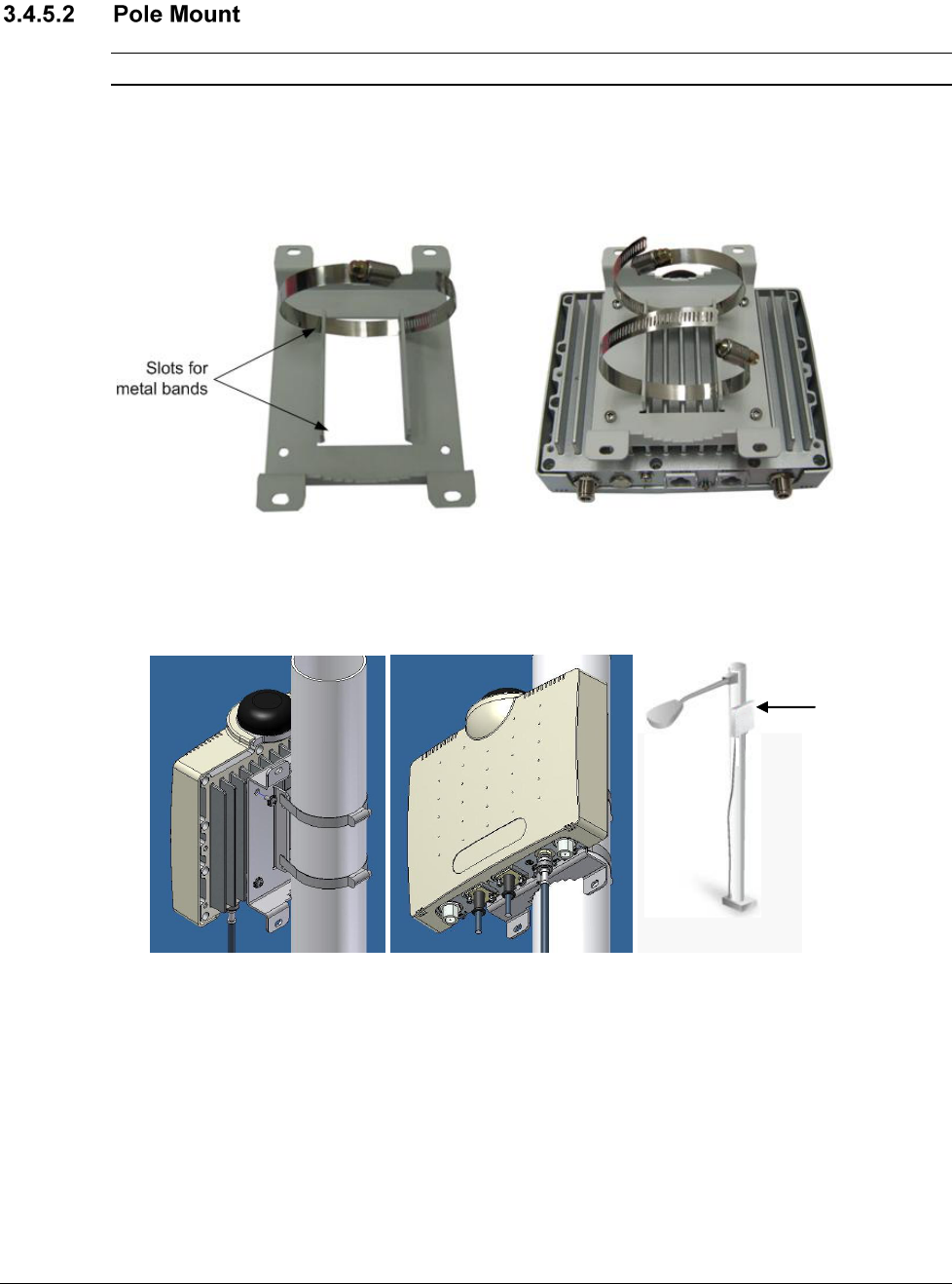
Note: The unit can be attached to any pipe or pole with a 1.75” to 10" diameter.
To mount the Pico Base on a pole
1. Assemble the wall-mounting bracket to the rear side of the unit (rib-side) – see 3.4.2.
2. Insert the metal bands in the bracket slots, as shown below.
3. Mount the unit on the pole, using the metal bands and close the bands tightly around the
pole.
4. Secure the metal bands with their screws. See following figure.
Figure 5. Pole Mount
Pole mounted
Pico Base

21
3.4.6 Antenna Connections
IMPORTANT!
THE PART OF THE ANTENNA THAT IS CONNECTED TO THE CENTRAL PIN OF THE
ANTENNA CONNECTOR SOULD BE COVERED BY ISOLATION MATERIAL WHICH IS
SUFFICIENTLY RESISTANT TO DEGRADATION BY ULTRA-VIOLET (UV) RADIATION.
Note: See 2.1.3 for antenna grounding requirements.
Connect the omni-antennas to the N-Type ANT1 and ANT2 connectors and connect the
grounding lug to the common ground.
Caution: This device has been designed to operate with the antenna described below, and
having a maximum gain of 7.15dBi. Other antennas or having an antenna with a gain greater
than 7.15dBi are strictly prohibited for use with this device. The required antenna impedance is
50Ω.
Antenna Information: MAXRAD model MFB 9155
The installation of this equipment and the antenna must be performed by a professional.
22
3.4.7 Connect the Pico Base Data Adapter
The Data Adapter is a combined data and power adapter that interfaces to the customer’s
Outdoor Unit wireless device and is used to power the Pico Base and to distribute data.
The Data Adapter unit includes a single output RJ-45 connector (for connection to an IEEE802.3
compatible device) that provides bi-directional 10/100 Base-T data and power to the outdoor
equipment over a Cat5e cable.
The unit receives power from 100V to 240V AC using an IEC-320-C14 industry standard
connector.
Note: The AC power supply cord should be 3 wires, 18 AWG minimum, with length less than 4.5
m, safety certified according to national rules.
To connect the Pico Base Data Adapter
1. Interconnect the Pico Base DC/Ethernet port and the Data Adapter ODU IF port, using a
Cat5E shielded cable (not supplied).
Note: The indoor to outdoor CAT5 cable max length should not exceed 100m.
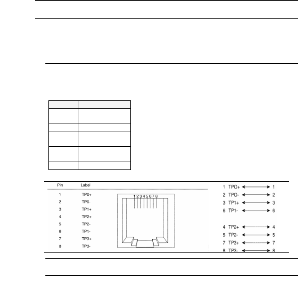
Refer to the following table for the ODU I/F connector pin out.
Table 2. ODU I/F port pin-out
Pin No.
Description
1
ETH Data
2
ETH Data
3
ETH Data
4
+55V
5
+55V
6
ETH Data
7
RTN (-)
8
RTN (-)
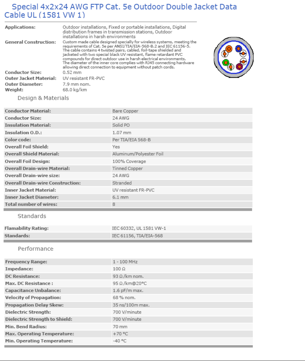
Refer to the following figure for the Ethernet cable pin out.
Note: The Cat5e Ethernet cable is not included. Please refer to Appendix B – IDU to ODU
Cable Specifications for detailed technical specifications.
23
2. Connect the Data Adapter to a Switch/Router by interconnecting the Data Adapters’
Ethernet port and the Switch/Router 10/100 Base T-port using a Cat5e cable.
3. Connect the Data Adapter to the 110V/220V AC mains using the supplied cable.
IMPORTANT!
BEFORE CONNECTING THE DATA ADAPTER TO THE MAIN OUTLET VERIFY THAT ALL SYSTEM COMPONENTS ARE
PROPERLY INSTALLED. MAKE SURE THAT ALL CABLE CONNECTORS ARE SECURELY POSITIONED IN THE
APPROPRIATE PORTS.
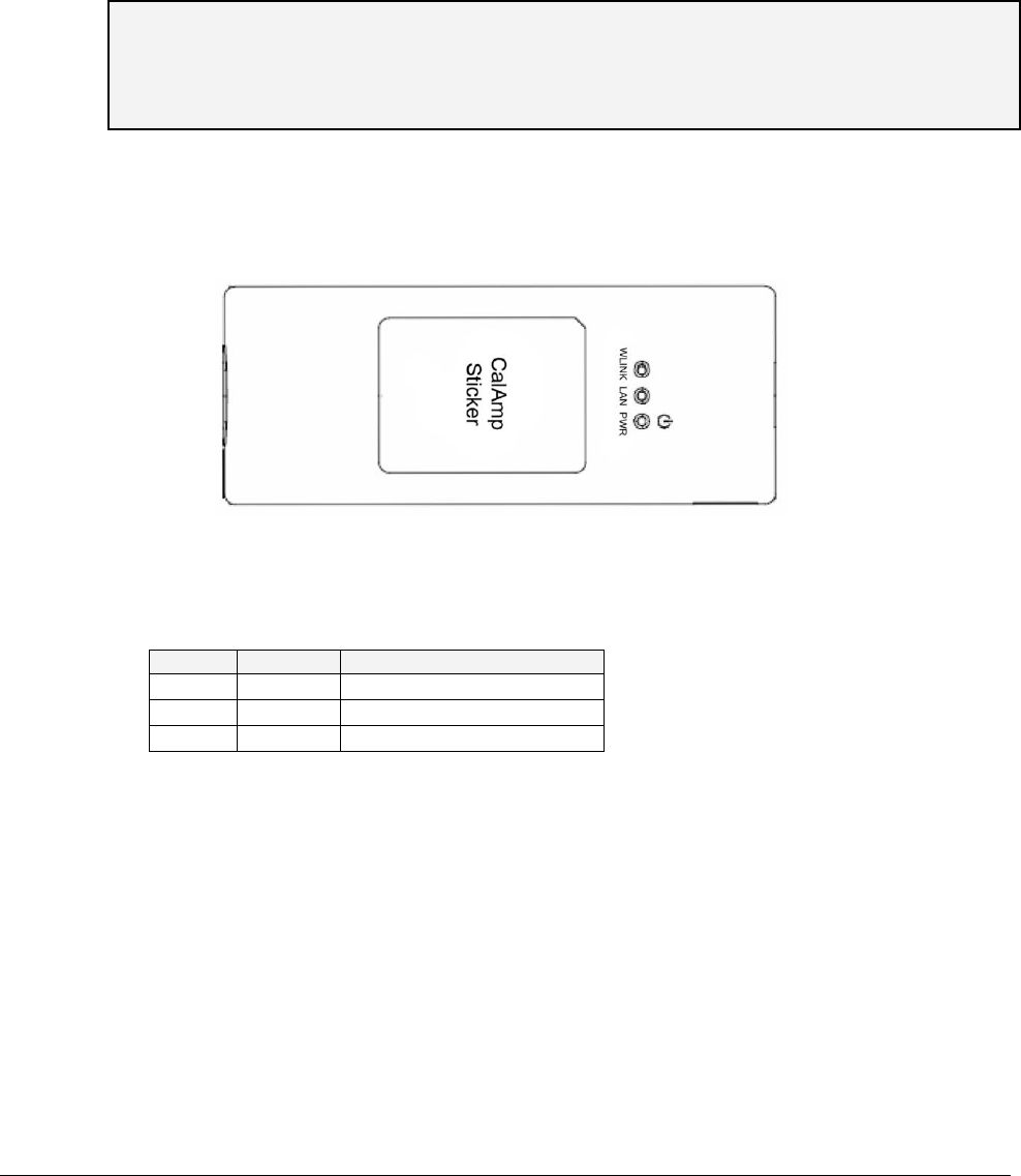
4. Verify that the Data Adapter LEDs, located on the front panel, are
Green
indicating an OK
status.
Data Adapter LED Indicators
Figure 6: Data Adapter Front Panel
The table below provides a description of the Data Adapter LED indicators.
Table 3. Data Adapter LED Description
LED
Color
Description
PWR
Green
Input power is connected
LAN
Green
LAN link/activity display
Ready
Green
System ready display
24
4 S
Se
et
tu
up
p
The initial setup procedure consists of:
Configuring the computers’ network parameters and connecting the Pico Base to the Web
interface
Verifying IP connectivity
4.1 Connecting Pico Base to Web Interface
To configure computer network parameters and connect the Pico Base unit to the
Web Interface
1. Interconnect the unit and the computer Ethernet ports using the Ethernet cable.
2. Configure the computers’ network parameters
Click the Start menu and choose Control Panel.
In the Control Panel, click Network and Internet Connections.
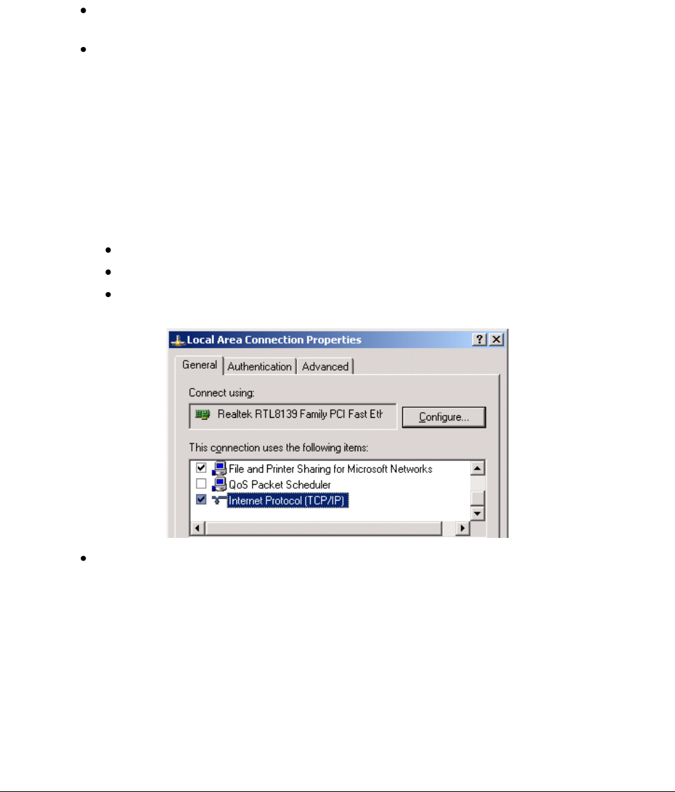
Click Network Connections and then double-click Local Area Connection. The Local Area
Connections Properties dialog appears with the General tab displayed by default.
In the Items list, select “Internet Protocol (TCP*IP)” and click the Properties button.
The “Internet Protocol (TCP/IP) Properties” dialog appears.
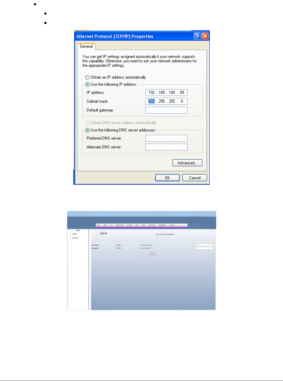
25
Assign your computer the following IP address and subnet. In the IP address area:
Enter the IP address 192.168.100.99
Enter the subnet 255.255.255.0
3. Open your WEB browser and enter 192.168.100.100. The following Login window
appears.
4.2 Verifying IP Connectivity
Refer to the CalAmp NMS User Manual

26
5 T
Tr
ro
ou
ub
bl
le
es
sh
ho
oo
ot
ti
in
ng
g
5.1 No IP connectivity
If there is no IP connectivity between the Pico Base unit and the NMS, perform the following
steps:
1. Interconnect computer and Pico Base Console connector (serial connection), located on the
units’ bottom panel.
2. In the terminal type the command: showIPAddr. The Pico Base IP address will be
displayed.
3. Try to ping the Pico Base unit address.
4. If connectivity is still not established, contact CalAmp customer support
5.2 No Serial Connection
If there is no serial connection when using the serial cable perform the following:
Verify IP connectivity using ping to the Pico Base unit IP address (see 5.1).
If there is no IP connectivity - verify the power connections.
If the power connections are OK, however there is still no serial connection or IP
connectivity, contact CalAmp customer support.

27
A
Ap
pp
pe
en
nd
di
ix
x
A
A
–
–
S
Sp
pe
ec
ci
if
fi
ic
ca
at
ti
io
on
ns
s
Radio and Modem
Frequency
903.90-926.10 MHz for 3.5 MHz Channels
904.65-925.30 MHz for 5 MHz Channels
905.75-924.20 MHz for 7 MHz Channels
907.25-922.70 MHz for 10 MHz Channels
Radio Access Method
IEEE802.16-2005 (16e OFDMA)
Operation Mode
TDD
Channel Bandwidth
3.5Mhz, 5 MHz, 7Mhz, 10 MHz
Frequency Resolution
0.25 MHz
Antennas
Integral Omni (default)
Number of Antennas
2
Default Antenna
Omni
Antennas Connectors
2x N-Type, 50 ohm, lightning protected
Diversity Support
2x2, STC/MIMO-SM
Output Power [P1dB]
2 x 5W;
Output Power (average)
27 dBm +/-1dB maximum
FFT/Modulation
512/1024 FFT points;
QPSK, 16QAM, 64QAM
FEC
Convolution Code and Turbo Code
TPC
10dB
Synchronization
GPS or IEEE1588 (optional)
Configuration and Management
Management
SNMP
SNMP Agent
SNMP ver 2 client: MIB II (RFC 1213), Private MIBs
Software Upgrade
FTP
Remote Configuration
FTP
Power Interface
Input
37-56VDC
Power Consumption
45Watt maximum
Environmental
Operating Temperature
-40 C to +55 C
Operating Humidity
5%-95% non condensing, Weather protected
Standards and Compliances
EMC
FCC part 15, subpart B, class B
ETSI EN 301489-1/4
Safety
TUV-UL 60950-1
IEC 61950-1
Environmental
ETS 300 019:
Part 2-1 T 1.2 & part 2-2 T 2.3
Part 2-4 T 4.1E

28
Enclosure
Type3R (IP66)
Immunity
EN61000-4-2
EN61000-4-4
EN61000-4-5
Radio
FCC Part 15 Subpart C
Industry Canada RSS-210
ETSI EN302 326
Mechanical
Dimensions [HxWxD]
24cm x 20cm x 4cm
Weight
<4Kg
29
A
Ap
pp
pe
en
nd
di
ix
x
B
B
–
–
I
ID
DU
U
t
to
o
O
OD
DU
U
C
Ca
ab
bl
le
e
S
Sp
pe
ec
ci
if
fi
ic
ca
at
ti
io
on
ns
s

30
A
Ap
pp
pe
en
nd
di
ix
x
C
C
–
–
C
Co
on
ns
so
ol
le
e
C
Co
on
nn
ne
ec
ct
to
or
r
Important! The Console connector should be closed in normal condition and is only intended
for the use of an authorized technician.
The chassis has RJ-45 maintenance female connector, used by a technician to connect a
“console”.
The port is used (by maintenance personnel) to communicate with the processor when the
normal management interfaces cannot be used. The console port is based on RS-232 serial
standard and support a standard terminal connection.
The Console port enables the technician to configure and monitor the Pico DST unit through CLI
(Command Language Interface) for low level debug.
The following table provides a description of the connector pin out.
Table 4: Maintenance connector
Pin Number
Type
1
TX
2
RX
5
GND
The serial cable used to connect the Pico Base
Console port
to the console is supplied by
CalAmp:
Cable Type – Cat5
Cable Connectors – DB9F; RJ45
Cable Length – 2m
31
A
Ap
pp
pe
en
nd
di
ix
x
D
D
-
-
M
Me
ec
ch
ha
an
ni
ic
ca
al
l
D
Dr
ra
aw
wi
in
ng
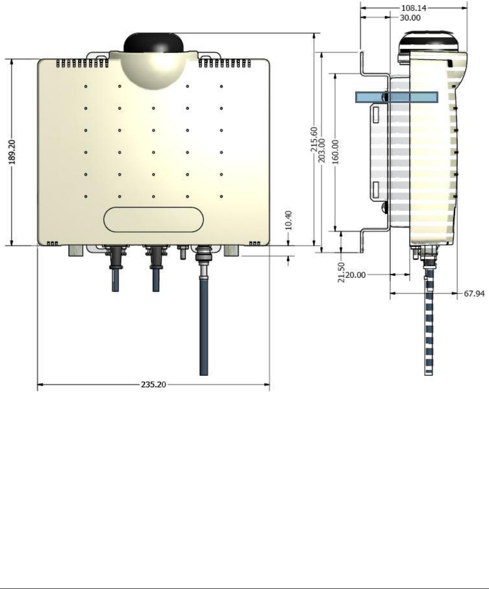
g
The following figure shows the Pico Base units’ dimensions (and with the mounting bracket).