CalAmp Wireless Networks 2424016-001 T-96SR Telemetry Transceiver/Modem User Manual HNETmanual
CalAmp Wireless Networks Corporation T-96SR Telemetry Transceiver/Modem HNETmanual
UserManual.wiki
>
CalAmp Wireless Networks
>
2424016-001 User Manual
>
Modem manual
Contents
1.
Transceiver manual
2.
Modem manual
Modem manual
Navigation menu
Upload a User Manual
Namespaces
Wiki Guide
HTML
PDF
Info
Views
User Manual
Discussion / Help
Navigation
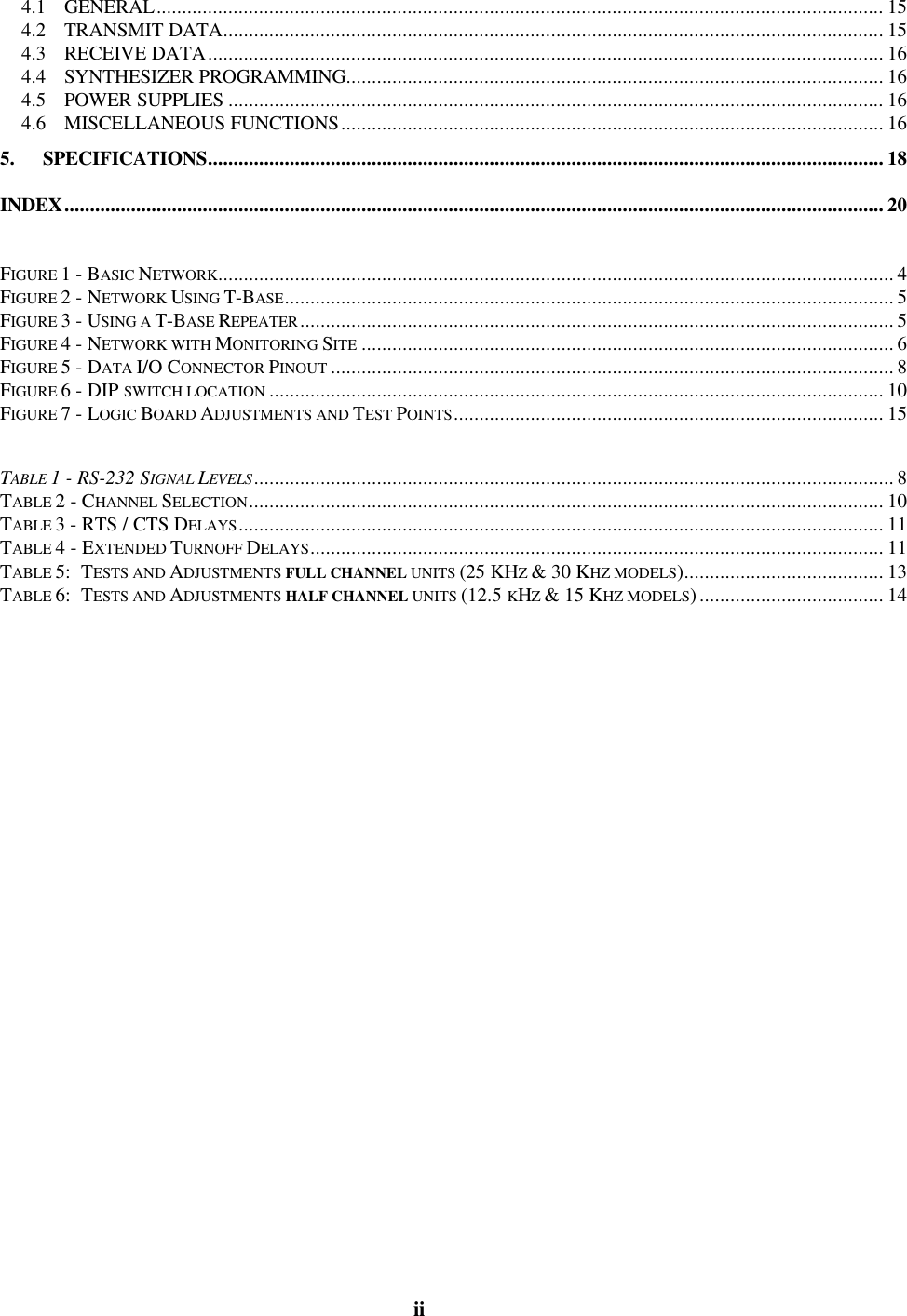
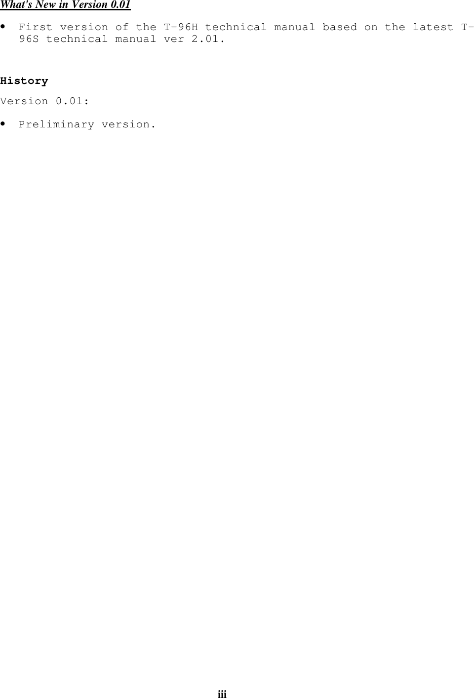
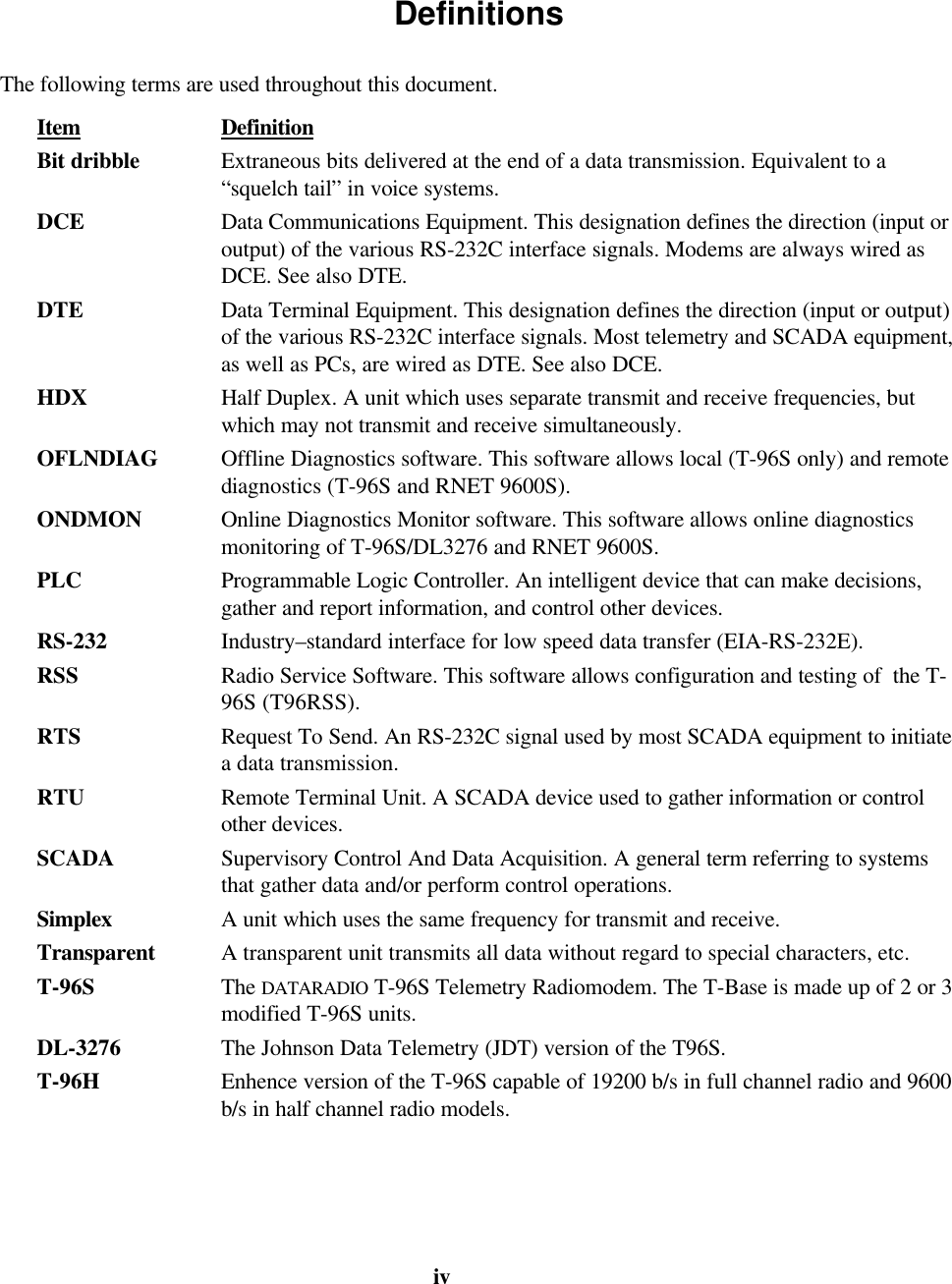
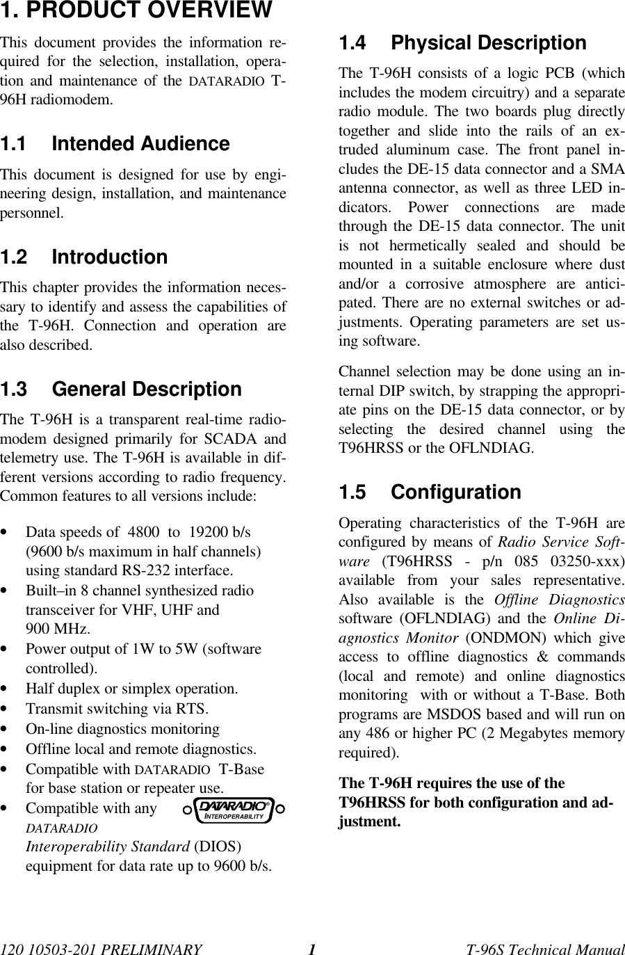
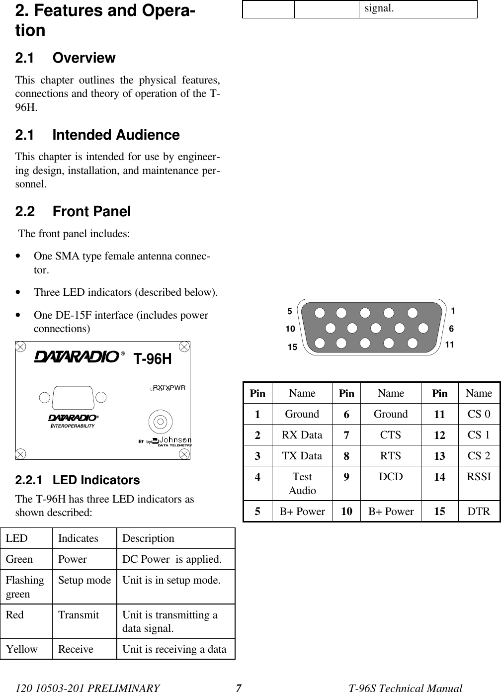
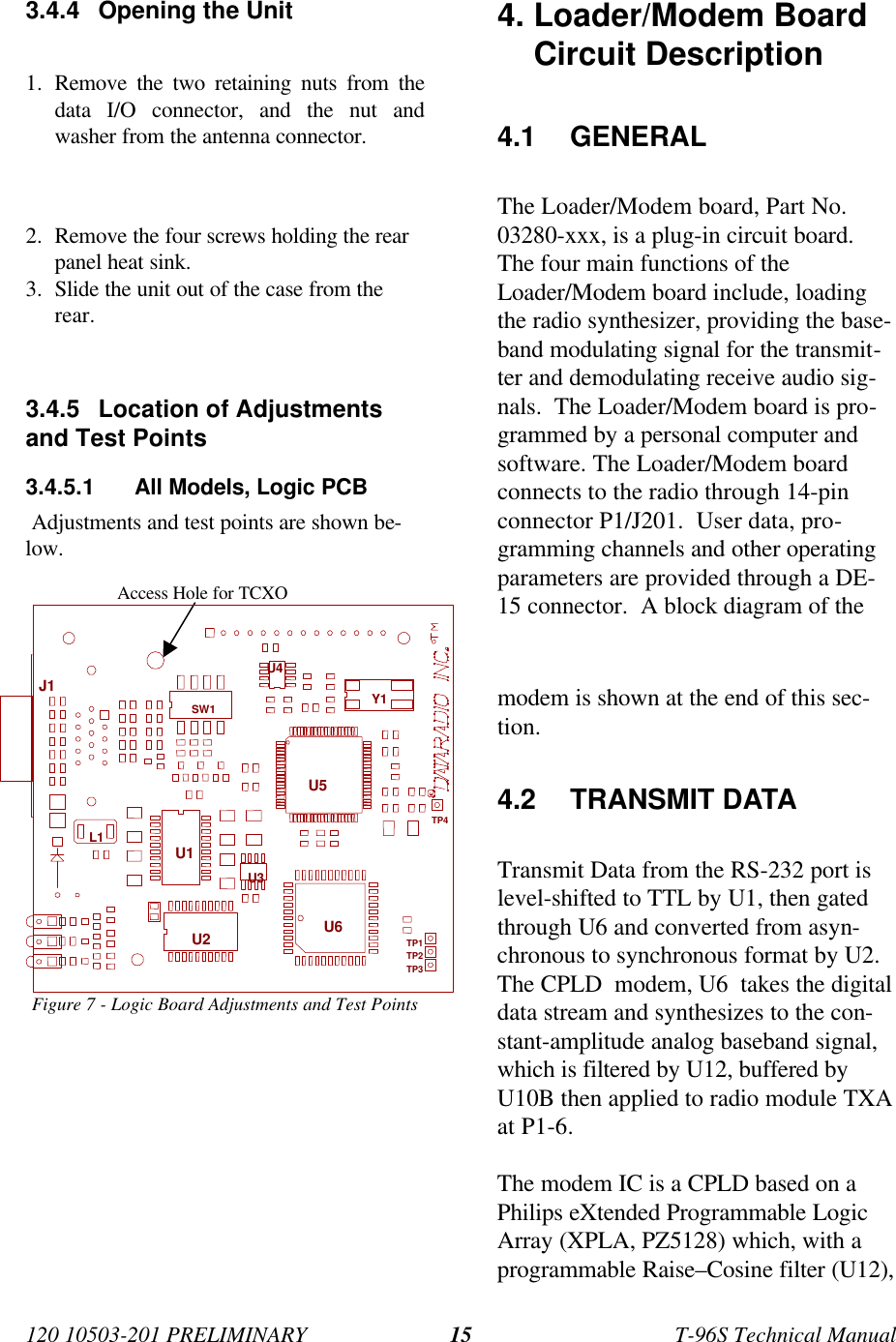
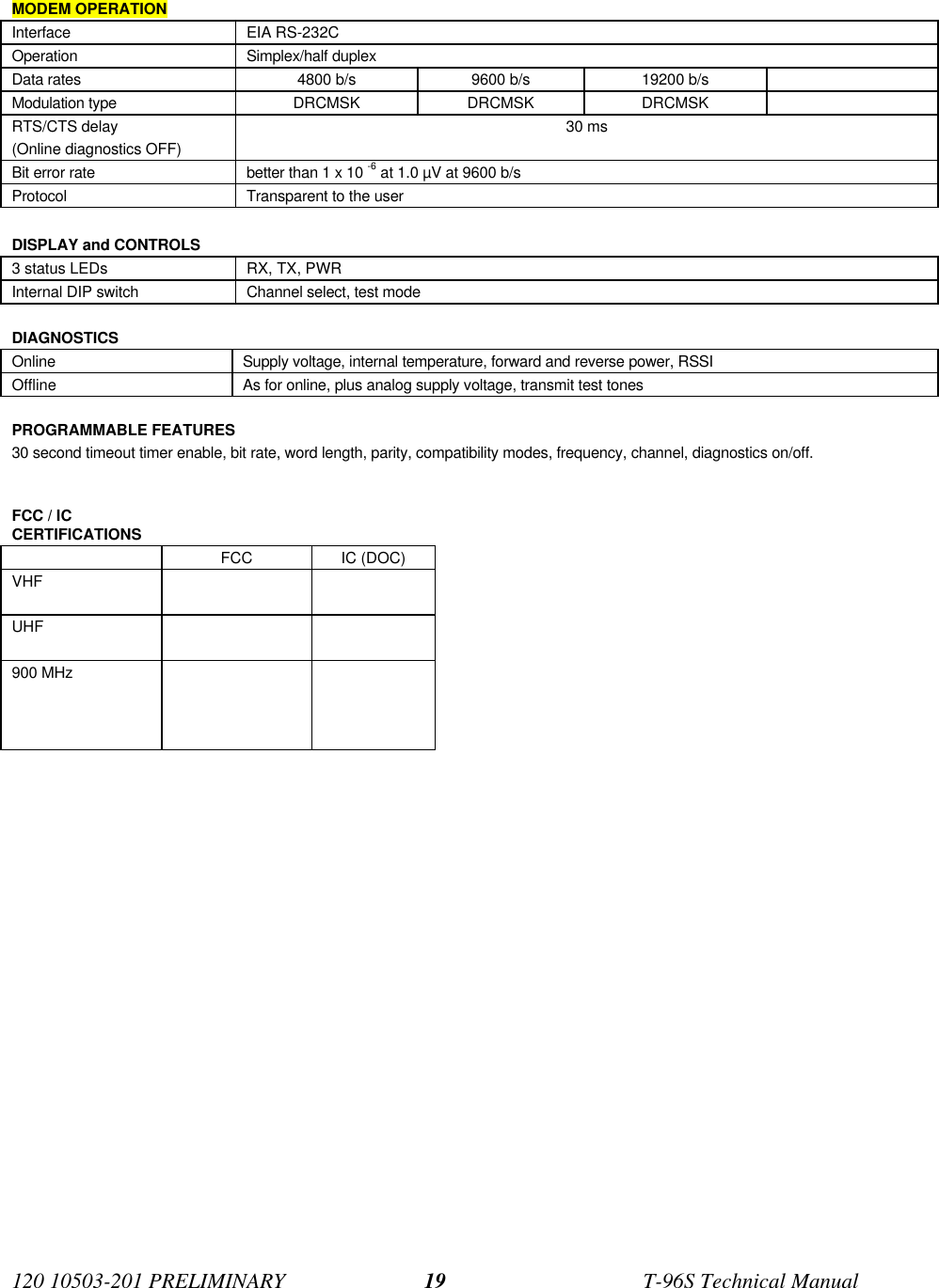
![120 10503-201 PRELIMINARY T-96S Technical Manual21.6 Catalog Numbers A T-96H may be identified from its catalognumber.CATALOG NUMBERSFormat is TH[radio][band][channel spacing]0radio22 VHF12 UHF92 900band (frequencies in MHz)1380 - 4032403 - 4193419 - 4354132 – 150 435 - 4515150 – 174 450 - 470 928 - 9606464 - 4807480 - 4968496 - 512channel spacing (frequencies in MHz)115.0 12.5 12.5330.0 25.0 25.0For example, a TH12530 is a UHF, 450-470 MHz unit with25 kHz channel spacing.1.7 Factory TechnicalSupport The Technical Support departments ofDATARADIO and Johnson Data Telemetry(JDT) provide customer assistance on techni-cal problems and serve as an interface withfactory repair facilities. They can bereached in the following ways: DATARADIO Inc. 5500 Royalmount Ave, suite 200 Town of Mount Royal Quebec, Canada H4P 1H7 Technical support hours: Monday to Friday9:00 AM to 5:00 PM, Eastern Time,. phone: +1 514 737-0020 fax: +1 514 737-7883Email address: support@dataradio.com Johnson Data Telemetry Corp. Customer Service Department 299 Johnson Avenue, P.O. Box 1733 Waseca, MN 56093-0833 Technical support hours: Monday to Friday9:00 AM to 5:00 PM, Central Time,. phone: 800 992-7774 and +1 507 835-6911 fax: 507 835-6969Email address: support@johnsondata.com1.8 Product Warranty Warranty information may be obtained bycontacting your sales representative.1.9 Replacement Parts This product is normally not field service-able, except by the replacement of completeunits. Specialized equipment and training isrequired to repair logic boards and radiomodules. Contact Technical Support for service infor-mation before returning equipment. A Tech-nical Support representative may suggest asolution eliminating the need to returnequipment.1.9.1 Factory Repair When returning equipment for repair, youmust request an RMA (Returned MaterialAuthorization) number. The Tech Supportrepresentative will ask you several questionsto clearly identify the problem. Please givethe representative the name of a contact per-son who is familiar with the problem, shouldquestions arise during servicing of the unit. Customers are responsible for shippingcharges for returned units. Units in warrantywill be repaired free of charge unless there isevidence of abuse or damage beyond theterms of the warranty. Units out of warrantywill be subject to service charges. Informa-tion about these charges is available fromTechnical Support.](https://usermanual.wiki/CalAmp-Wireless-Networks/2424016-001.Modem-manual/User-Guide-7126-Page-7.png)