CalAmp Wireless Networks 2424016-001 T-96SR Telemetry Transceiver/Modem User Manual HNETmanual
CalAmp Wireless Networks Corporation T-96SR Telemetry Transceiver/Modem HNETmanual
Contents
- 1. Transceiver manual
- 2. Modem manual
Modem manual

T-96H
Radio Modem
Technical Manual
version 0.01
PRELIMINARY
The entire contents of this manual and the Radio Service Software
described in this manual are copyright 1998 by DATARADIO Inc.
Copyright DATARADIO Inc.
August 1998
part no.: 120 10504-001
i
Table of Contents
1. PRODUCT OVERVIEW ............................................................................................................................ 1
1.1 INTENDED AUDIENCE ................................................................................................................................. 1
1.2 INTRODUCTION .......................................................................................................................................... 1
1.3 GENERAL DESCRIPTION .............................................................................................................................. 1
1.4 PHYSICAL DESCRIPTION.............................................................................................................................. 1
1.5 CONFIGURATION ........................................................................................................................................ 1
1.6 CATALOG NUMBERS ................................................................................................................................... 2
1.7 FACTORY TECHNICAL SUPPORT................................................................................................................... 2
1.8 PRODUCT WARRANTY ................................................................................................................................ 2
1.9 REPLACEMENT PARTS................................................................................................................................. 2
1.9.1 Factory Repair.................................................................................................................................. 2
1.10 DIAGNOSTICS AND REMOTE COMMANDS ................................................................................................. 3
1.10.1 Addressing.................................................................................................................................... 3
1.10.2 Online Diagnostics ....................................................................................................................... 3
1.10.3 Offline Diagnostics....................................................................................................................... 4
1.10.4 Remote Commands ....................................................................................................................... 4
1.11 NETWORK CONFIGURATION .................................................................................................................... 4
1.11.1 Basic Network............................................................................................................................... 4
1.11.2 Network Using T-Base .................................................................................................................. 5
1.11.3 Network Using T-Base Repeater ................................................................................................... 5
1.11.4 Network Using T-96H for Online Diagnostics............................................................................... 6
2. FEATURES AND OPERATION ................................................................................................................ 7
1.1 OVERVIEW ................................................................................................................................................. 7
2.1 INTENDED AUDIENCE ................................................................................................................................. 7
2.2 FRONT PANEL ............................................................................................................................................ 7
2.2.1 LED Indicators ................................................................................................................................. 7
2.3 DTE PORT INTERFACE ............................................................................................................................... 8
2.3.1 RS-232 Inteface Signal Levels........................................................................................................... 8
2.3.2 Interface Port.................................................................................................................................... 9
2.3.3 Interface Signal Description ............................................................................................................. 9
2.4 CHANNEL SELECTION ............................................................................................................................... 10
2.5 OPERATION .............................................................................................................................................. 10
2.5.1 RTS/CTS Timing ............................................................................................................................. 11
2.5.2 XTAL mode..................................................................................................................................... 11
2.5.3 Extended Turnoff ............................................................................................................................ 11
3. ADJUSTMENTS AND MAINTENANCE ................................................................................................ 12
1.1 OVERVIEW ............................................................................................................................................... 12
3.1 INTENDED AUDIENCE ............................................................................................................................... 12
3.2 EQUIPMENT REQUIRED ............................................................................................................................. 12
3.3 MAINTENANCE INTERVALS ....................................................................................................................... 12
3.4 T96H ADJUSTMENTS................................................................................................................................ 12
3.4.1 Preliminary Verification ................................................................................................................. 12
3.4.2 Basic Adjustments........................................................................................................................... 12
3.4.3 Tests & ajustments .......................................................................................................................... 12
3.4.4 Opening the Unit............................................................................................................................. 15
3.4.5 Location of Adjustments and Test Points......................................................................................... 15
3.4.5.1 All Models, Logic PCB ..........................................................................................................................15
4. LOADER/MODEM BOARD CIRCUIT DESCRIPTION ....................................................................... 15
ii
4.1 GENERAL.............................................................................................................................................. 15
4.2 TRANSMIT DATA................................................................................................................................. 15
4.3 RECEIVE DATA.................................................................................................................................... 16
4.4 SYNTHESIZER PROGRAMMING......................................................................................................... 16
4.5 POWER SUPPLIES ................................................................................................................................ 16
4.6 MISCELLANEOUS FUNCTIONS.......................................................................................................... 16
5. SPECIFICATIONS.................................................................................................................................... 18
INDEX................................................................................................................................................................ 20
FIGURE 1 - BASIC NETWORK.................................................................................................................................... 4
FIGURE 2 - NETWORK USING T-BASE....................................................................................................................... 5
FIGURE 3 - USING A T-BASE REPEATER.................................................................................................................... 5
FIGURE 4 - NETWORK WITH MONITORING SITE ........................................................................................................ 6
FIGURE 5 - DATA I/O CONNECTOR PINOUT .............................................................................................................. 8
FIGURE 6 - DIP SWITCH LOCATION ........................................................................................................................ 10
FIGURE 7 - LOGIC BOARD ADJUSTMENTS AND TEST POINTS.................................................................................... 15
TABLE 1 - RS-232 SIGNAL LEVELS............................................................................................................................. 8
TABLE 2 - CHANNEL SELECTION............................................................................................................................ 10
TABLE 3 - RTS / CTS DELAYS.............................................................................................................................. 11
TABLE 4 - EXTENDED TURNOFF DELAYS................................................................................................................ 11
TABLE 5: TESTS AND ADJUSTMENTS FULL CHANNEL UNITS (25 KHZ & 30 KHZ MODELS)....................................... 13
TABLE 6: TESTS AND ADJUSTMENTS HALF CHANNEL UNITS (12.5 KHZ & 15 KHZ MODELS).................................... 14

iii
What's New in Version 0.01
• First version of the T-96H technical manual based on the latest T-
96S technical manual ver 2.01.
History
Version 0.01:
• Preliminary version.

iv
Definitions
The following terms are used throughout this document.
Item Definition
Bit dribble Extraneous bits delivered at the end of a data transmission. Equivalent to a
“squelch tail” in voice systems.
DCE Data Communications Equipment. This designation defines the direction (input or
output) of the various RS-232C interface signals. Modems are always wired as
DCE. See also DTE.
DTE Data Terminal Equipment. This designation defines the direction (input or output)
of the various RS-232C interface signals. Most telemetry and SCADA equipment,
as well as PCs, are wired as DTE. See also DCE.
HDX Half Duplex. A unit which uses separate transmit and receive frequencies, but
which may not transmit and receive simultaneously.
OFLNDIAG Offline Diagnostics software. This software allows local (T-96S only) and remote
diagnostics (T-96S and RNET 9600S).
ONDMON Online Diagnostics Monitor software. This software allows online diagnostics
monitoring of T-96S/DL3276 and RNET 9600S.
PLC Programmable Logic Controller. An intelligent device that can make decisions,
gather and report information, and control other devices.
RS-232 Industry–standard interface for low speed data transfer (EIA-RS-232E).
RSS Radio Service Software. This software allows configuration and testing of the T-
96S (T96RSS).
RTS Request To Send. An RS-232C signal used by most SCADA equipment to initiate
a data transmission.
RTU Remote Terminal Unit. A SCADA device used to gather information or control
other devices.
SCADA Supervisory Control And Data Acquisition. A general term referring to systems
that gather data and/or perform control operations.
Simplex A unit which uses the same frequency for transmit and receive.
Transparent A transparent unit transmits all data without regard to special characters, etc.
T-96S The DATARADIO T-96S Telemetry Radiomodem. The T-Base is made up of 2 or 3
modified T-96S units.
DL-3276 The Johnson Data Telemetry (JDT) version of the T96S.
T-96H Enhence version of the T-96S capable of 19200 b/s in full channel radio and 9600
b/s in half channel radio models.

120 10503-201 PRELIMINARY T-96S Technical Manual1
1. PRODUCT OVERVIEW
This document provides the information re-
quired for the selection, installation, opera-
tion and maintenance of the DATARADIO T-
96H radiomodem.
1.1 Intended Audience
This document is designed for use by engi-
neering design, installation, and maintenance
personnel.
1.2 Introduction
This chapter provides the information neces-
sary to identify and assess the capabilities of
the T-96H. Connection and operation are
also described.
1.3 General Description
The T-96H is a transparent real-time radio-
modem designed primarily for SCADA and
telemetry use. The T-96H is available in dif-
ferent versions according to radio frequency.
Common features to all versions include:
• Data speeds of 4800 to 19200 b/s
(9600 b/s maximum in half channels)
using standard RS-232 interface.
• Built–in 8 channel synthesized radio
transceiver for VHF, UHF and
900 MHz.
• Power output of 1W to 5W (software
controlled).
• Half duplex or simplex operation.
• Transmit switching via RTS.
• On-line diagnostics monitoring
• Offline local and remote diagnostics.
• Compatible with DATARADIO T-Base
for base station or repeater use.
• Compatible with any
DATARADIO
Interoperability Standard (DIOS)
equipment for data rate up to 9600 b/s.
1.4 Physical Description
The T-96H consists of a logic PCB (which
includes the modem circuitry) and a separate
radio module. The two boards plug directly
together and slide into the rails of an ex-
truded aluminum case. The front panel in-
cludes the DE-15 data connector and a SMA
antenna connector, as well as three LED in-
dicators. Power connections are made
through the DE-15 data connector. The unit
is not hermetically sealed and should be
mounted in a suitable enclosure where dust
and/or a corrosive atmosphere are antici-
pated. There are no external switches or ad-
justments. Operating parameters are set us-
ing software.
Channel selection may be done using an in-
ternal DIP switch, by strapping the appropri-
ate pins on the DE-15 data connector, or by
selecting the desired channel using the
T96HRSS or the OFLNDIAG.
1.5 Configuration
Operating characteristics of the T-96H are
configured by means of Radio Service Soft-
ware (T96HRSS - p/n 085 03250-xxx)
available from your sales representative.
Also available is the Offline Diagnostics
software (OFLNDIAG) and the Online Di-
agnostics Monitor (ONDMON) which give
access to offline diagnostics & commands
(local and remote) and online diagnostics
monitoring with or without a T-Base. Both
programs are MSDOS based and will run on
any 486 or higher PC (2 Megabytes memory
required).
The T-96H requires the use of the
T96HRSS for both configuration and ad-
justment.
INTEROPERABILITY
®
120 10503-201 PRELIMINARY T-96S Technical Manual2
1.6 Catalog Numbers
A T-96H may be identified from its catalog
number.
CATALOG NUMBERS
Format is TH[radio][band][channel spacing]0
radio
22 VHF
12 UHF
92 900
band (frequencies in MHz)
1380 - 403
2403 - 419
3419 - 435
4132 – 150 435 - 451
5150 – 174 450 - 470 928 - 960
6464 - 480
7480 - 496
8496 - 512
channel spacing (frequencies in MHz)
115.0 12.5 12.5
330.0 25.0 25.0
For example, a TH12530 is a UHF, 450-470 MHz unit with
25 kHz channel spacing.
1.7 Factory Technical
Support
The Technical Support departments of
DATARADIO and Johnson Data Telemetry
(JDT) provide customer assistance on techni-
cal problems and serve as an interface with
factory repair facilities. They can be
reached in the following ways:
DATARADIO Inc.
5500 Royalmount Ave, suite 200
Town of Mount Royal
Quebec, Canada H4P 1H7
Technical support hours: Monday to Friday
9:00 AM to 5:00 PM, Eastern Time,.
phone: +1 514 737-0020
fax: +1 514 737-7883
Email address: support@dataradio.com
Johnson Data Telemetry Corp.
Customer Service Department
299 Johnson Avenue, P.O. Box 1733
Waseca, MN 56093-0833
Technical support hours: Monday to Friday
9:00 AM to 5:00 PM, Central Time,.
phone: 800 992-7774 and
+1 507 835-6911
fax: 507 835-6969
Email address: support@johnsondata.com
1.8 Product Warranty
Warranty information may be obtained by
contacting your sales representative.
1.9 Replacement Parts
This product is normally not field service-
able, except by the replacement of complete
units. Specialized equipment and training is
required to repair logic boards and radio
modules.
Contact Technical Support for service infor-
mation before returning equipment. A Tech-
nical Support representative may suggest a
solution eliminating the need to return
equipment.
1.9.1 Factory Repair
When returning equipment for repair, you
must request an RMA (Returned Material
Authorization) number. The Tech Support
representative will ask you several questions
to clearly identify the problem. Please give
the representative the name of a contact per-
son who is familiar with the problem, should
questions arise during servicing of the unit.
Customers are responsible for shipping
charges for returned units. Units in warranty
will be repaired free of charge unless there is
evidence of abuse or damage beyond the
terms of the warranty. Units out of warranty
will be subject to service charges. Informa-
tion about these charges is available from
Technical Support.
120 10503-201 PRELIMINARY T-96S Technical Manual3
1.10 Diagnostics and Remote
Commands
Diagnostics and remote commands are proc-
essed using the T96H Offline Diagnostics
software (OFLNDIAG). Diagnostics can be
monitored using the T96H Online Diagnos-
tics Monitor program (ONDMON).
The T-96H has the following diagnostic and
command features:
Online diagnostics. Information is automati-
cally sent by each unit at the beginning
of every transmission. May be disabled
for back compatibility with DATARADIO
T-Modem 96 or Motorola RNET 9600.
Offline diagnostics. Information is sent by a
specific unit in response to an inquiry by
the master or monitoring station.
Remote commands. Commands may be sent
by the master or monitoring station to
any specific remote unit.
1.10.1 Addressing
Each T-96H has addressing capability which
is used for diagnostics and remote commands
only. Two addresses are used:
ID Number: This value (maximum 1023) is
assigned at the factory but may be modi-
fied using the T96RSS. The ID Number
is used to uniquely identify the T-96H
for remote commands and offline diag-
nostics. The ID Number may have val-
ues within the range of 1 to 99,999,999
but multiples of 1024 should not be
used.
Short ID: This value is the low order 10 bits
of the ID Number. It is used to identify
online diagnostics only. It may not be
modified directly using the T96HRSS; it
is always derived from the ID Number.
All units within a network should have
unique Short ID numbers to avoid ambi-
guity in Online Diagnostics reports.
Either the T96HRSS or OFLNDIAG may be
used to check the value of the Short ID.
When setting up a network, we recommend
checking each unit to make sure that there is
no duplication of Short ID numbers. Dupli-
cations may be resolved by changing the ID
Number.
If ID Numbers are set so that their value is
within the range of 1 to 1023, the ID Number
and the Short ID will always have the same
value. Customers may find this to be a con-
venience.
1.10.2 Online Diagnostics
Online diagnostics (statistics) require the use
of a network configuration such as that
specified in section 1.11.2. or 1.11.4 Online
diagnostics do not interfere with normal net-
work operation. The following information is
gathered:
• Supply voltage
• Internal temperature
• Forward and reverse power in watts
(T96S models only)
• Received signal strength in dBm
Each T-96H can accumulate these statistics
for the last 15 stations heard. The accumu-
lated values may be displayed using the
OFLNDIAG or dynamically monitored by
the Online Diagnostics Monitor program
(ONDMON).
120 10503-201 PRELIMINARY T-96S Technical Manual4
1.10.3 Offline Diagnostics
Offline diagnostics are statistics returned in
response to a specific request to a particular
station. The use of this feature requires that
network operation temporarily be suspended.
The following information may be gathered
and displayed via the OFLNDIAG:
• Supply voltage
• Analog supply voltage
• Internal temperature
• Received signal strength in dBm
• Forward and relected power in watts
(T96S models only)
1.10.4 Remote Commands
The following commands may be sent re-
motely (using the OFLNDIAG).
• Begin test transmission (several types
available).
• Get statistics (diagnostics).
• Sample network statistics (monitoring
online diagnostics).
• Get parameters (configuration) from re-
mote unit.
Sending remote commands and receiving re-
sponses is done with the host application off-
line.
1.11 Network Configuration
The T-96H is designed to replace wire lines in SCADA, telemetry and control applications. The
RS-232 serial port allows direct connection to PLCs (Programmable Logic Controllers) or RTUs
(Remote Terminal Units). Several network configurations are described in the sections that follow.
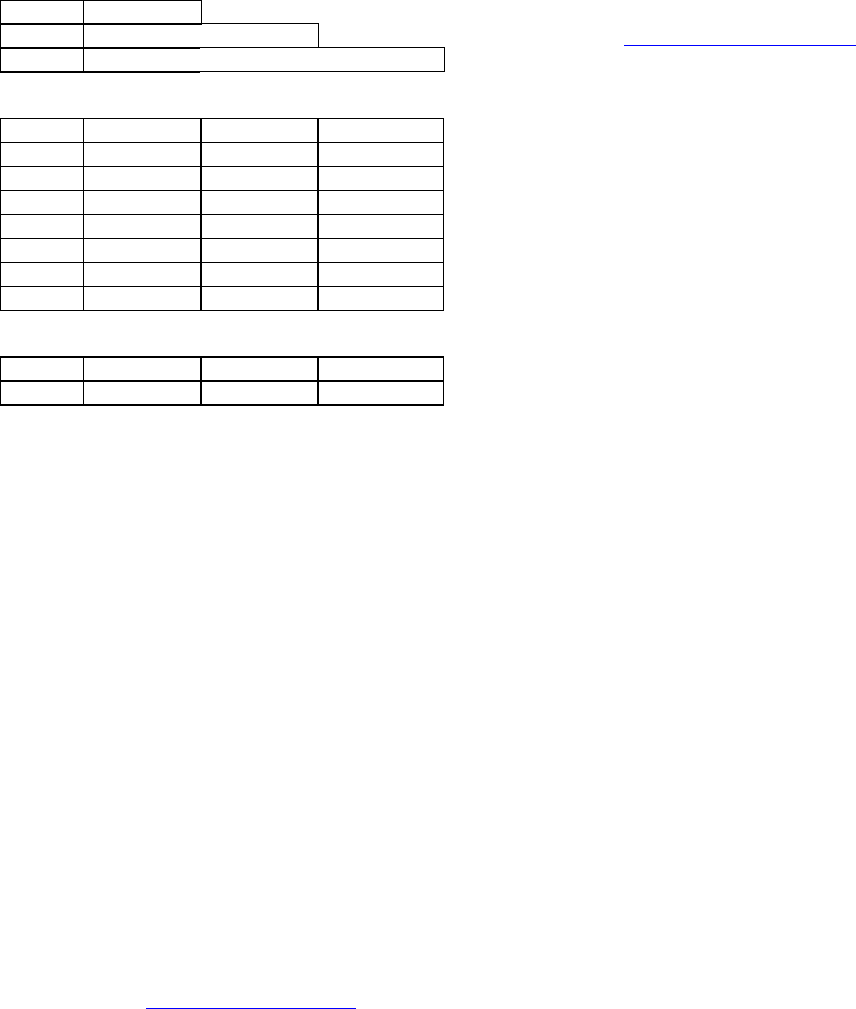
1.11.1 Basic Network
This configuration has the following characteristics:
• Master station may be half duplex or
simplex.
• Online diagnostics are not available in
real time.
• Remote and local diagnostics, accumu-
lated online diagnostics and control are
available by disconnecting the master
PLC and substituting a PC running the
T96H Offline Diagnostics software
(OFLNDIAG).
PLC
Master
PLC T96H
T96H
T96H
PLC
Figure 1 - Basic Network
120 10503-201 PRELIMINARY T-96S Technical Manual5
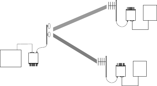
1.11.2 Network Using T-Base
This configuration has the following characteristics:
• Master station may be full duplex (du-
plexer required), half duplex or simplex.
• Online diagnostics are available using
the Online Diagnostics Monitor pro-
gram (ONDMON) without disrupting
network activity.
• Remote and local diagnostics, statistics
and control are available using the T-
96H OFLNDIAG.
• The T-Base provides output of online
diagnostic information which could be
processed by the T-96H ONDMON pro-
gram or by a user-supplied network
management program. Contact your
sales representative for further informa-
tion.
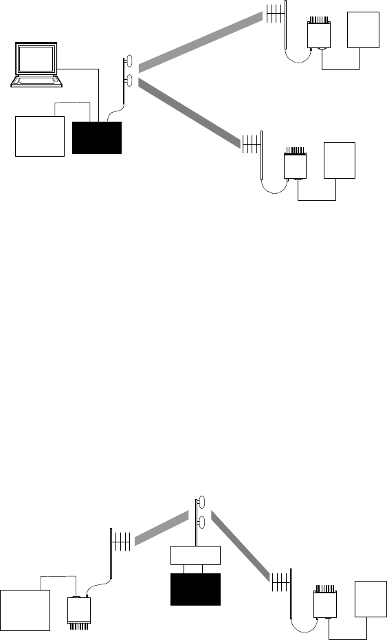
1.11.3 Network Using T-Base Repeater
This configuration has the following characteristics:
• Master station and all remotes must be
half duplex.
• Any of the network types described in
sections 1.11.1, 1.11.2 or 1.11.4 may be
used with a T-Base repeater.
• The RTS/CTS delays for each T-96H in
the system must be extended as shown in
section 2.5.1
PLC
Master
PLC
T96H
T96H
T-Base
PC for online
diagnostics PLC
Figure 2 - Network Using T-Base
PLC
Master
PLC T96H
T96H
T-Base
repeater
duplexer
Figure 3 - Using a T-Base Repeater
120 10503-201 PRELIMINARY T-96S Technical Manual6
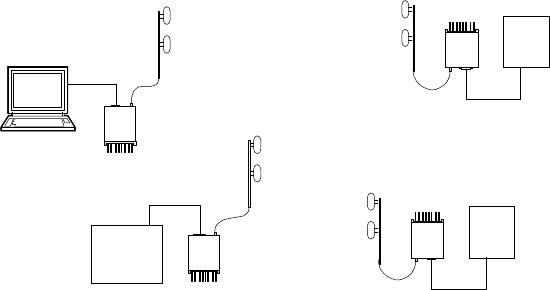
1.11.4 Network Using T-96H for Online Diagnostics
This configuration has the following characteristics:
• Master station may be half duplex or
simplex.
• Accumulated online diagnostics for a
maximum of 15 stations are available at
a monitoring site (monitoring site must
be in range of all remotes).
• Online diagnostics are available in real
time at the monitoring site.
• Remote offline diagnostics, statistics and
control are available from the monitoring
site by temporarily disabling network
activity.
Online diagnostics are accumulated in the
monitoring T-96H for the last 15 stations
heard. This information may be viewed using
the OFLNDIAG. For larger networks, the T-
96H can output raw diagnostic data only,
which may be interpreted for network man-
agement by the Dataradio ONDMON pro-
gram or by a user-supplied software pro-
gram. Contact your sales representatives for
more information.
PLC
Master
PLC T96H
T96H
T96H
T96H
PC for online
diagnostics PLC
Figure 4 - Network with Monitoring Site
120 10503-201 PRELIMINARY T-96S Technical Manual7
2. Features and Opera-
tion
2.1 Overview
This chapter outlines the physical features,
connections and theory of operation of the T-
96H.
2.1 Intended Audience
This chapter is intended for use by engineer-
ing design, installation, and maintenance per-
sonnel.
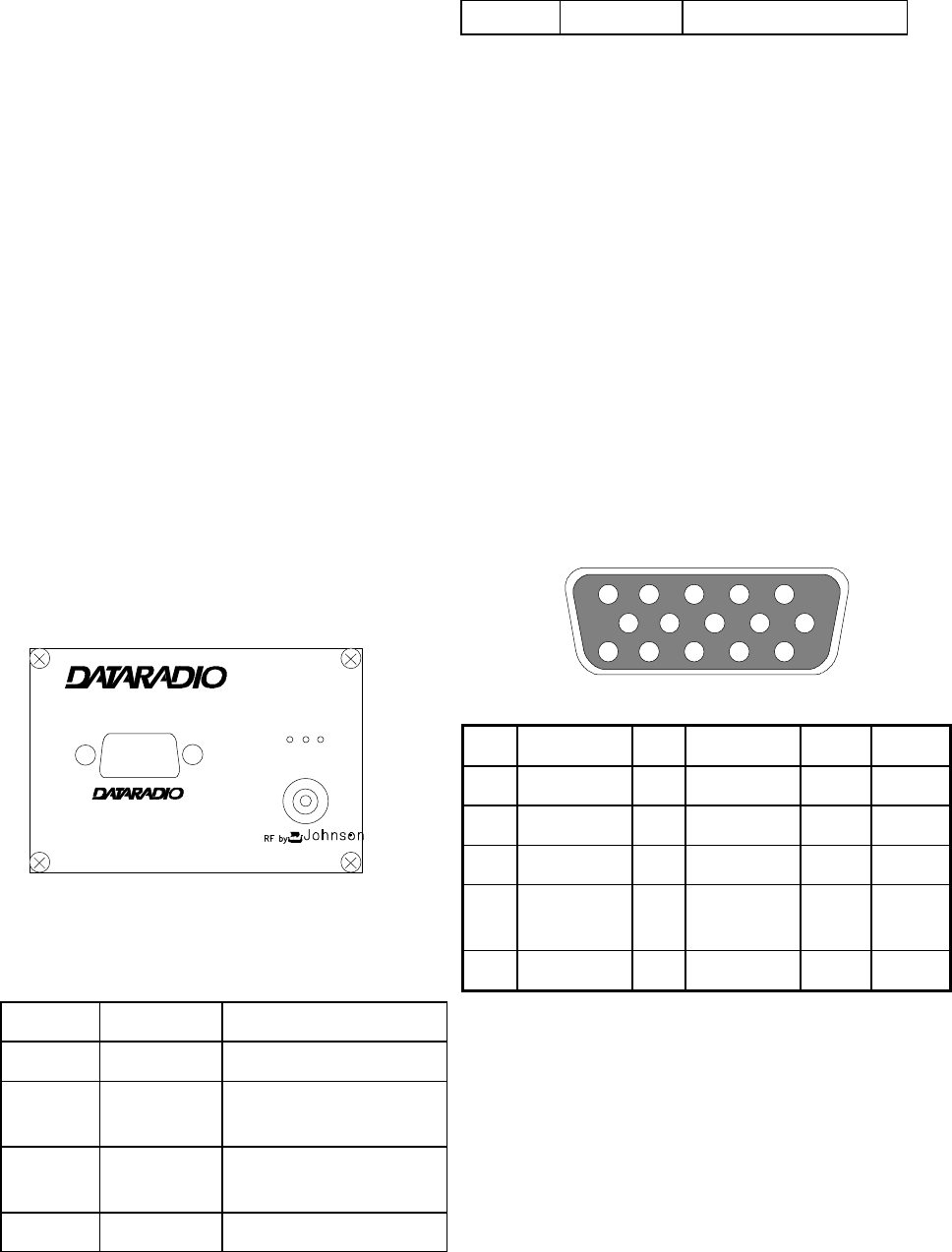
2.2 Front Panel
The front panel includes:
• One SMA type female antenna connec-
tor.
• Three LED indicators (described below).
• One DE-15F interface (includes power
connections)
T-96H
RX
TX
PWR
I
NTEROPERABILITY
®
DATA TELEMETR
Y
®
2.2.1 LED Indicators
The T-96H has three LED indicators as
shown described:
LED Indicates Description
Green Power DC Power is applied.
Flashing
green Setup mode Unit is in setup mode.
Red Transmit Unit is transmitting a
data signal.
Yellow Receive Unit is receiving a data
signal.
15
11
10
6
5
1
Pin Name Pin Name Pin Name
1Ground 6Ground 11 CS 0
2RX Data 7CTS 12 CS 1
3TX Data 8RTS 13 CS 2
4Test
Audio 9DCD 14 RSSI
5B+ Power 10 B+ Power 15 DTR

120 10503-201 PRELIMINARY T-96S Technical Manual8
2.3 DTE Port Interface
2.3.1 RS-232 Inteface Signal
Levels
In the descriptions of data signals, the fol-
lowing conventions are used:
Table 1 - RS-232 Signal Levels
Term Alternates Signal level
ON asserted, spacing +3 to +15 V
OFF dropped, marking -3 to -15 V
Figure 5 - Data I/O Connector Pinout
120 10503-201 PRELIMINARY T-96S Technical Manual9
2.3.2 Interface Port
The T-96H signals are defined as DCE.
Connection to user DTE is made via a DE-
15 female connector. This connection meets
the DATARADIO Interoperability Standard
(DIOS).
Users can build a suitable cable by referring
to the connector pinout and the Interface Sig-
nal Description given in the next section. A
cable for connection to a PC AT type DE-9
connector is available from DATARADIO as
p/n 730 03267-001.
Important Note: The T96H RSS kit, used to
configure the T-96H, includes a special setup
cable, p/n 730 03266-001. Do not use this
cable to connect a user application. Doing
so will result in the T-96H switching to
“setup mode”, in which case it will not
transmit or receive user data. The green LED
flashes to indicate that the unit is in this
mode.
2.3.3 Interface Signal Description
B+ power (input). 10 - 16 VDC (13.3V
nominal), maximum 2 A.
RX Data. Received data from T-96H to
DTE.
TX Data. Transmit data from DTE to
T-96H.
CTS. Clear to Send. Asserted when the
T-96H is ready to accept TX Data.
RTS. Request to Send. Causes the T-
96H to transmit when asserted by the
DTE.
DCD. Data Carrier Detect. Asserted by
the T-96H when a data signal is being
received.
DTR. Data Terminal Ready. Asserted by
the T96HRSS/OFLNDIAG to select
setup mode. Do not connect to this pin
for user applications.
Test Audio. Output signal used during
adjustment and testing.
RSSI. Output signal used during testing.
120 10503-201 PRELIMINARY T-96S Technical Manual10
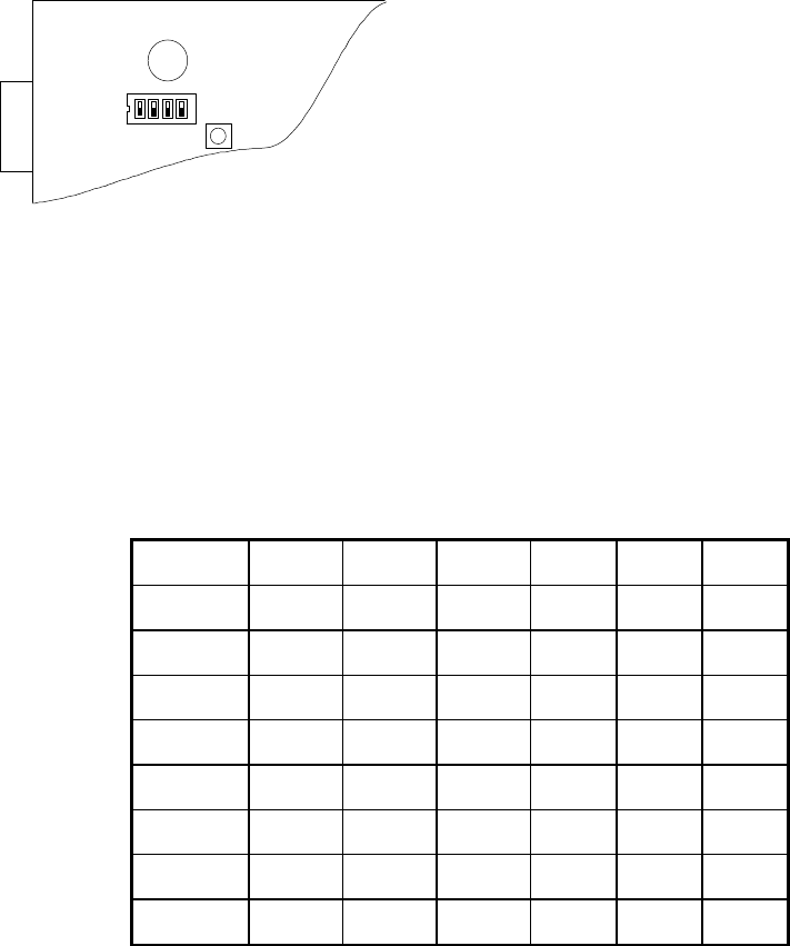
2.4 Channel Selection
Channel frequencies for 8 channels are se-
lected using the T96HRSS. Once selected,
the current operating channel may be selected
in one of three ways:
1. By setting the channel on the internal
DIP switch. CS0 to CS2 on the inter-
face connector must be left discon-
nected.
2. By strapping connections on the interface
connector. There is a 10KΩ pull up re-
sistor on each line (CS0 to CS2). The
DIP switch channel settings must be all
OFF.
3. By selecting the channel from the
T96RSS or the OFLNDIAG programs.
The DIP switch channel settings must
be all OFF and CS0 to CS2 on the in-
terface connector must be discon-
nected (open).
Table 2 - Channel Selection
Channel SW1-3 SW1-2 SW1-1 CS 2 CS 1 CS 0
1on on on gnd gnd gnd
2on on off gnd gnd open
3on off on gnd open gnd
4on off off gnd open open
5off on on open gnd gnd
6off on off open gnd open
7off off on open open gnd
8off off off open open open
In the table, “gnd” indicates that the pin should be connected to ground (pin 1 or 6)
2.5 Operation
The T-96H operates transparently at the
speed set using the Radio Service Software
(T96HRSS) and is designed to operate unat-
tended. Basic operation is as follows.
1. The DTE starts a data transfer by as-
serting RTS. CTS is returned after the
transmitter has been keyed and a modem
synchronization preamble sent.
See Table 3 - RTS / CTS Delays for
actual value.
2. Data are transmitted as long as RTS is
asserted and the PTT timer, if enabled,
has not expired. RTS can be dropped
after the last stop bit of the last character
has been given to the T-96H. CTS will
be dropped when the last character has
been transmitted on the network.
SW1
F
igure 6 - DIP switch location

120 10503-201 PRELIMINARY T-96S Technical Manual11
3. In the idle mode, i.e. no transmission or
reception, RX Data will be held in the
idle (i.e. “marking”) condition.
4. When a valid radio data signal is re-
ceived, DCD will be asserted and data
will be delivered.
5. When the radio carrier is dropped, the T-
96H will clamp RX Data idle (marking)
again and drop DCD. At 19200 b/s a
few extraneous bits may be delivered af-
ter the carrier is dropped (sometimes
called “bit dribble”). User software
should take this possibility into account.
2.5.1 RTS/CTS Timing
The T-96H asserts CTS after RTS has been
asserted and a sufficient time has elapsed to
allow modem synchronization. The times are
fixed at the factory and are not user–adjust-
able.
Repeater mode (Extended time) must be set
(via the T96HRSS) if the unit is to commu-
nicate through a repeater.
Times are increased if online diagnostics are
enabled, as shown in the columns diag. on.
Table 3 - RTS / CTS Delays
RTS/CTS delay (normal) RTS/CTS delay (extended)
Speed diag. off diag. on diag. off diag. on
1200 b/s 50 ms 144 ms 80 ms 174 ms
2400 b/s 40 ms 87 ms 70 ms 117 ms
4800 b/s 30 ms 54 ms 60 ms 84 ms
9600 b/s 30 ms 41 ms 60 ms 71 ms
19200 b/s 30 ms 36 ms 60 ms 66 ms
2.5.2 XTAL mode
This mode extends all RTS/CTS delays by 5
ms for compatibility with earlier, crystal
controlled products (T-Modem 96, RNet
9600). Select this mode from the T96RSS.
2.5.3 Extended Turnoff
An end–of–transmission quiet period ap-
proximately 8 characters long can be invoked
on the T-96H by holding its tranmitter on
briefly after RTS is dropped. This quiet pe-
riod, which occurs between the last valid
data character and any possible extraneous
“noise” bits, may be of benefit to some DTE
that would otherwise be adversely affected
by the extraneous bits. This quiet period is
selected via the T96RSS.
Table 4 - Extended Turnoff Delays
Speed Quiet “turnoff” period
1200 b/s 70 ms
2400 b/s 35 ms
4800 b/s 16 ms
9600 b/s 8 ms
19200 b/s 4 ms
120 10503-201 PRELIMINARY T-96S Technical Manual12
3. Adjustments and
Maintenance
1.1 Overview
This chapter outlines the basic adjustment proce-
dures required upon initial installation and there-
after at prescribed maintenance intervals. Units
are delivered from the factory properly aligned
and tested on the frequencies specified at time of
order. Adjustment beyond that described in this
chapter is not required unless radio modules have
been tampered with or repaired. In such cases we
recommend complete factory re-alignment as
special test jigs are required.
3.1 Intended Audience
This chapter is intended for use by installation
and maintenance personnel.
3.2 Equipment Required
The adjustments described below require the fol-
lowing equipment:
• 13.3 VDC (nominal), 3A regulated power
supply.
• Radio service monitor (IFR or equivalent).
• Cable with SMA-male connector to connect
T-96H to the service monitor.
• T96H Radio Service Software (T96HRSS)
kit, including setup cable (p/n 085 03250-
xxx)
• A 486 PC (or better) to run the T96HRSS.
• Normal radio shop tools.
3.3 Maintenance Intervals
The adjustments described below should be done
once upon initial installation of the unit, and
thereafter at annual intervals or whenever a dete-
rioration in performance indicates that adjust-
ment may be required.
3.4 T96H Adjustments
3.4.1 Preliminary Verification
Before performing any adjustments, verify the
performance of the unit as shown in the Table 5
for full channel units in the Table 6 for half
channel units.
Important Note: Before proceeding make sure
that the service monitor has been calibrated
recently and has warmed up for at least the
time specified by its manufacturer.
Some reported frequency and deviation problems
have actually been erroneous indications from
service monitors that have not adequately
warmed up. This is particularly likely when field
service is done during winter months.
3.4.2 Basic Adjustments
Basic adjustments to be performed are:
1. Transmitter power output
2. TX/RX frequency
3. Transmitter deviation
4. Demodulated audio level
These adjustments should be performed in the
sequence shown above.
3.4.3 Tests & ajustments
Refer to the T96HRSS help file for parameter
information.
1. Connect the T-96H antenna connector to the
TX/RX input of the service monitor using a
suitable length of 50 ohm cable.
2. Connect the T-96H to a suitable power sup-
ply and adjust the supply voltage to 13.3
volts.
3. Using the setup cable (p/n 730 03266-001;
part of kit 085 03250-xxx) connect the
T-96H Data connector to the serial port of a
PC and run the T96HRSS program. This ca-
ble is required to put the T-96H into setup
mode.
4. Press GET to get the configuration of the
unit.
5. Refer to “Tests and Adjustments” tables re-
lated to the radio type (half or full channel).

120 10503-201 PRELIMINARY T-96S Technical Manual13
Table 5: Tests and Adjustments full channel units (25 KHz & 30 Khz models)
STEP ACTION EXPECTED
RESULTS at
25°°C
MEASURE
WITH IF NOT?
1Output Power
Press PTT Channel x
5 watts 1
+10%, -20%
Service monitor
set to read
power
Check T96HRSS maximum
power output setting: must
be set to 255 (means 5W)
Refer to factory tech
support.
2Frequency Error
Press PTT Channel x
±300 Hz Service monitor
set to read fre-
quency error
Open the unit (see 3.4.4)
Adjust the Frequency Ad-
just control on the TCXO 2
3Deviation
Press PTT Channel x
±4.0 kHz 3
+5%, -10%
Service monitor
set to read de-
viation with mid
(15 - 30 kHz) IF
filter.
Using T96HRSS, adjust TX
deviation with the up/down
arrows.
4Set the service monitor to generate a -80 dBm signal on the selected receive frequency. The
signal should be modulated with a 1.0 kHz tone.
5Demodulated Audio
• For 9600 b/s set
generator deviation
to ±2.5 kHz.
• For 1200 - 4800 b/s
set generator devia-
tion to ±4.0 kHz.
2.0 ±0.2 Vpp Oscilloscope
connected to
pin 4 of the data
I/O connector. 4
Using T96HRSS, adjust
receive audio level with the
up/down arrows.
612 dB SINAD
Set deviation to ±3 kHz.
Set IF filter to mid (15-
30 kHz), no audio filter.
≤ 0.5 µV 5Service monitor
set for SINAD.
Connect to pin
4 of the data
I/O connector 4.
Refer to factory technical
support.
7Distortion
Set deviation to ±3 kHz.
Set IF filter to mid (15-
30 kHz), no audio filter.
< 3% Service monitor
set for Distor-
tion. Connect to
pin 4 of the data
I/O connector 4.
Refer to factory technical
support.
1(unless you have set a lower value). Note that readings less than 5 watts may be due to losses in the cables used for testing.
Check also your wattmeter frequency calibration curve. Do not be too ready to condemn the transmitter.
2The TCXO adjustment is accessible through the hole next to the DIP switch on the logic board.
3The unit is automatically set to 19200 b/s (Bt.3) for this procedure. If the unit is later used at 9600 b/s (Bt.5) or 4800 b/s, the
deviation be will automatically set to ±3.0 kHz and ±4.0kHz respectively.
4Pin 4 is accessible by removing the cable connector hood. If you anticipate frequent need for access to this pin, solder a short
insulated lead to that pin on the cable connector and replace the hood. (The same signal is available at TP1 on the logic
board if the unit is open).
5If a psophometrically weighted filter is available on the service monitor, use 0.35 µV.

120 10503-201 PRELIMINARY T-96S Technical Manual14
Table 6: Tests and Adjustments half channel units (12.5 kHz & 15 Khz models)
STEP ACTION EXPECTED
RESULTS at
25°°C
MEASURE
WITH IF NOT?
1Output Power
Press PTT Channel x
5 watts 1
+10%, -20%
Service monitor
set to read
power
Check T96RSS maximum
power output setting: must
be set to 255 (means 5W)
Refer to factory tech
support.
2Frequency Error
Press PTT Channel x
±300 Hz Service monitor
set to read fre-
quency error
Open the uniit (see 3.4.4)
Adjust the Frequency Ad-
just control on the TCXO 2
3Deviation
Press PTT Channel x
±3.0 kHz 3
+5%, -10%
Service monitor
set to read de-
viation with mid
(15 - 30 kHz) IF
filter.
Using T96HRSS, adjust TX
deviation with the up/down
arrows.
4Set the service monitor to generate a -80 dBm signal on the selected receive frequency. The
signal should be modulated with a 1.0 kHz tone.
5Demodulated Audio
For 1200 - 4800 b/s set
generator deviation to
±2.0 kHz.
2.0 ±0.2 Vpp Oscilloscope
connected to
pin 4 of the data
I/O connector. 4
Using T96HRSS, adjust
receive audio level with the
up/down arrows.
612 dB SINAD
Set deviation to 1.5kHz.
Set IF filter to mid (15-
30 kHz), no audio filter.
≤ 0.5 µV 5Service monitor
set for SINAD.
Connect to pin
4 of the data
I/O connector 4.
Refer to factory technical
support.
7Distortion
Set deviation to 1.5kHz.
Set IF filter to mid (15-
30 kHz), no audio filter.
< 3% Service monitor
set for Distor-
tion. Connect to
pin 4 of the data
I/O connector 4.
Refer to factory technical
support.
1(unless you have set a lower value). Note that readings less than 5 watts may be due to losses in the cables used for
testing. Check also your wattmeter frequency calibration curve. Do not be too ready to condemn the transmitter.
2The TCXO adjustment is accessible through the hole next to the DIP switch on the logic board.
3The unit is automatically set to 9600 b/s (Bt.3) for this procedure. This T96H model has not been designed to
operate at 19200 b/s using half channel radios. If the unit is later used at 4800 b/s (Bt.5), the deviation will be
automatically set to ±2.0 kHz.
4Pin 4 is accessible by removing the cable connector hood. If you anticipate frequent need for access to this pin,
solder a short insulated lead to that pin on the cable connector and replace the hood. (The same signal is available
at TP1 on the logic board if the unit is open).
5If a psophometrically weighted filter is available on the service monitor, use 0.35 µV.

120 10503-201 PRELIMINARY T-96S Technical Manual15
3.4.4 Opening the Unit
1. Remove the two retaining nuts from the
data I/O connector, and the nut and
washer from the antenna connector.
2. Remove the four screws holding the rear
panel heat sink.
3. Slide the unit out of the case from the
rear.
3.4.5 Location of Adjustments
and Test Points
3.4.5.1 All Models, Logic PCB
Adjustments and test points are shown be-
low.
Figure 7 - Logic Board Adjustments and Test Points
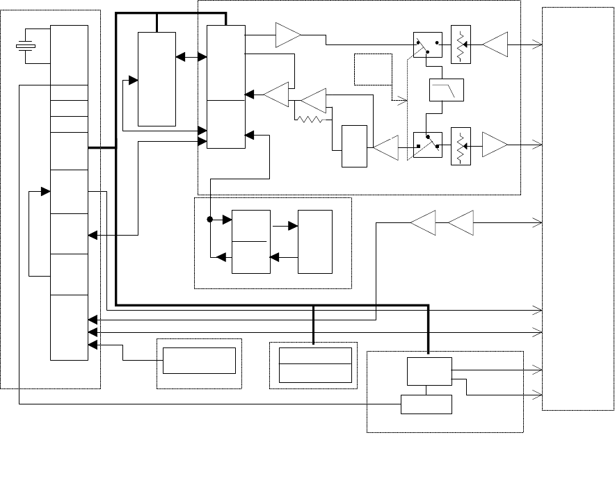
4. Loader/Modem Board
Circuit Description
4.1 GENERAL
The Loader/Modem board, Part No.
03280-xxx, is a plug-in circuit board.
The four main functions of the
Loader/Modem board include, loading
the radio synthesizer, providing the base-
band modulating signal for the transmit-
ter and demodulating receive audio sig-
nals. The Loader/Modem board is pro-
grammed by a personal computer and
software. The Loader/Modem board
connects to the radio through 14-pin
connector P1/J201. User data, pro-
gramming channels and other operating
parameters are provided through a DE-
15 connector. A block diagram of the
modem is shown at the end of this sec-
tion.
4.2 TRANSMIT DATA
Transmit Data from the RS-232 port is
level-shifted to TTL by U1, then gated
through U6 and converted from asyn-
chronous to synchronous format by U2.
The CPLD modem, U6 takes the digital
data stream and synthesizes to the con-
stant-amplitude analog baseband signal,
which is filtered by U12, buffered by
U10B then applied to radio module TXA
at P1-6.
The modem IC is a CPLD based on a
Philips eXtended Programmable Logic
Array (XPLA, PZ5128) which, with a
programmable Raise–Cosine filter (U12),
Access Hole for TCXO
SW1
L1
TP2
TP4
Y1
U3
U6
U2
U1
U4
TP1
TP3
U5
J1

120 10503-201 PRELIMINARY T-96S Technical Manual16
operates in DRCMSK1 mode at 4800,
9600 and 19200 bits/sec. It incorporates
a 7-bit hardware scrambler and uses
Differential (NRZI) encoding in
DRCMSK mode to minimize data pat-
tern-sensitivity. Electronic potentiometer
U9B (E-Pot), controlled by CPU U5, is
used to set the transmitter deviation by
amplitude adjustment of the baseband
signal.
4.3 RECEIVE DATA
Received signals are applied to the RXA
pin on P1-13 and amplified by U7A,
whose gain is set by the electronic po-
tentiometer U9A, then filtered by U12.
The same filter circuit is used for trans-
mission and reception: two analog multi-
plexer/demultiplexer gates (U11 A and
B) controlled by TX_EN line are used
for sharing. The filter U12 cut-off fre-
quency is programmable by the CPU,
based on the data rate. The analog signal
is then fed to Peak Detectors U7C and
U7D, to the slicer circuit U8C via U7B
and U8B. The resulting synchronous bit
stream is converted to asynchronous at
U2 and shifted to RS-232 levels by U1.
4.4 SYNTHESIZER
PROGRAMMING
The CPU programs the RF module syn-
thesizer serially on each Tx/Rx transi-
tion. Logic of U1 and U11A/B switch
the receive and transmit data path from
the modem to the radio and/or the exter-
nal serial port, under CPU control. The
CPU also controls the sync/async con-
1 DRCMSK = Differential Raise Cosine Minimum
Shift Keying
verter U2, the filter cut-off frequency,
the serial port handshake lines, and the
LED indicators via Q1-3.
Three channel select inputs, ESD pro-
tected by D1,2,3, in parallel with the on-
board DIP switches, are read by the CPU
to select the active channel. The fourth
DIP switch puts the unit in TEST mode,
which sends a test, tone (data rate/4).
4.5 POWER SUPPLIES
The main DC power (13.3V nom.) com-
ing from J1.5,10 is filtered out for tran-
zient and then sent directly to power-up
the radio module at P1.2. Voltage
Regulator U14 (AVCC) provides 5 V
for the receiver RX_5V and analog mo-
dem circuitry, while U13 (DVCC) pro-
vides 5V for the CPU and other digital
logic.
4.6 MISCELLANEOUS
FUNCTIONS
U4 generates a power-on reset for the
CPU and U3 is a temperature sensor
used by the firmware to compensate for
variations in RSSI.
The RF module’s RSSI output, P1-12, is
read by an analog input on the CPU,
which implements a squelch threshold in
software. Other analog inputs are used
to read ambient temperature (used to
correct RSSI variations) and various in-
ternal voltages (B+_LVL, AVCC, etc.).
The DTR_PGM input, J2-10, puts the
CPU in programming mode in which the
CPU accepts commands and setup data
from the Radio Service Software.
120 10503-201 PRELIMINARY T-96S Technical Manual17
CONTROL BUS
U3
MONITORING
SIO 2
SIO 1
CTC
U5 U6 U8A U7A
RXA
U8D
PEAK
DETECT
U7C,D,B
CPLD
Modem
RXS
DRIVER
U1
RCVR
DE15
RXD
CTS
DCD
DTR
TXD
RTS
SYNTHESIZER
TX SUPPLY
RX SUPPLY
MODEM
CPU
RS232
Y1
DIAGNOSTICS
RSSI
RADIO
MODULE
POWER SUPPLY
LEDS
DIP SWITCHES
TEMPERATURE
VOLTAGES 5.0V
13.3V
RESET
U10C U10D
U2
SYNC-ASYNC
CONVERTER
U13,
U14,F1
RESET
RAM
ROM
W.DOG
DIGITAL
I/O
A/D
Logic
Gates
U4
TXA
TXA
E-Pot
U9B
E-Pot
U9A
U10B
U8B
Slicer
Level
U8C
Controlled
by CPU'
TX_EN
Line
U12
Figure 8 – Logic / Modem board Block Diagram

120 10503-201 PRELIMINARY T-96S Technical Manual18
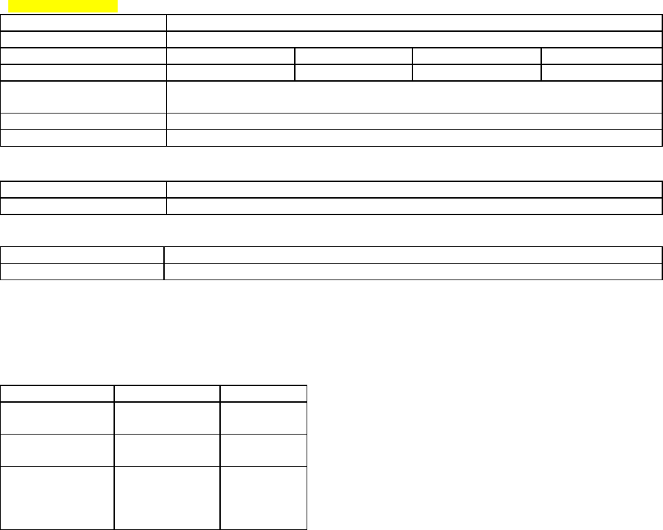
5. Specifications
GENERAL
VHF UHF 900 MHz
Frequency 132 - 174 MHz 403 - 512 MHz 928 - 960 MHz
Channel spacing 15 or 30 kHz 12.5 or 25 kHz 12.5 or 25 kHz
Operating temperature -30°C to +60°C
Supply voltage 10 - 16 VDC (applied through the interface connector)
RX Current at 13.3 VDC 120 mA 125 mA 135 mA
TX Current at 13.3 VDC 1.6 A 1.8 A 2.3 A
RX/TX bandwidth 18 MHz (132 - 150)
24 MHz (150 - 174)
16 MHz except
20 MHz (450 - 470)
32 MHz
Nominal Dimensions 2.25” (H) x 3.25” (W) x 4.75” (L)
RF connector SMA-F
Interface connector DE-15F high density D-subminiature
RECEIVER
VHF UHF 900 MHz
Sensitivity (12 dB SINAD) < 0.35 µV *
Selectivity (25 or 30 kHz) 75 dB typical
70 dB minimum
72 dB typical
65 dB minimum
Selectivity (12.5 or 15 kHz) 65 dB typical
60 dB minimum
63 dB typical
60 dB minimum
Intermodulation 75 dB typical
70 dB minimum
72 dB typical
70 dB minimum
Spurious rejection 75 dB typical
70 dB minimum
75 dB typical
70 dB minimum
FM hum & noise -48 dB typical *
-45 dB max (30 kHz) *
-40 dB max (15 kHz) *
-40 dB max (25 kHz)*
-35 dB max (12.5 kHz)*
Conducted spurious < -57 dBm maximum
* psophometrically weighted filter
TRANSMITTER
VHF UHF 900 MHz
Power output 1 - 5 watts 1 - 5 watts 1 - 5 watts
Spurious and harmonics -63 dBc (-26 dBm) typ
-57dBc (-20 dBm) max
-75 dBc (-38 dBm) typ
-63dBc (-26 dBm) max
-75 dBc (-38 dBm) typ
-57 dBc (-20 dBm) max
Frequency stability 2.5 ppm 1.5 ppm
FM hum and noise -50 dB typ (30 kHz)
-45 dB max (30 kHz)
-40 dB max (15 kHz)
-50 dB typical (25 kHz)
-45 dB max 25 kHz)
-40 dB max (12.5 kHz)
-50 dB typ (25 kHz)
-40 dB max (25 kHz)
-35 dB max (12.5 kHz)
Attack time < 7 ms
Duty cycle 50% at full power, 30 seconds maximum transmit time
120 10503-201 PRELIMINARY T-96S Technical Manual19
MODEM OPERATION
Interface EIA RS-232C
Operation Simplex/half duplex
Data rates 4800 b/s 9600 b/s 19200 b/s
Modulation type DRCMSK DRCMSK DRCMSK
RTS/CTS delay
(Online diagnostics OFF)
30 ms
Bit error rate better than 1 x 10 -6 at 1.0 µV at 9600 b/s
Protocol Transparent to the user
DISPLAY and CONTROLS
3 status LEDs RX, TX, PWR
Internal DIP switch Channel select, test mode
DIAGNOSTICS
Online Supply voltage, internal temperature, forward and reverse power, RSSI
Offline As for online, plus analog supply voltage, transmit test tones
PROGRAMMABLE FEATURES
30 second timeout timer enable, bit rate, word length, parity, compatibility modes, frequency, channel, diagnostics on/off.
FCC / IC
CERTIFICATIONS
FCC IC (DOC)
VHF
UHF
900 MHz
120 10503-201 20 T-96S Technical Manual
INDEX
A
addressing 3
adjustments 11
equipment required 11
location of controls 14
maintenance intervals 11
B
bit dribble 10
C
channel selection 9
commands 4
compatibility 10
configuration 1
D
diagnostics 3
offline 4
online 3, 6
E
extended delay 10
extended turnoff 10
F
full channel units 12
H
half channel units 13
I
ID number 3
L
LED indicators 7
N
networks 4
O
operation 9
P
performance verification 11
R
RS-232 signal description 8
RS-232 signal levels 7
RTS/CTS timing 10
S
specifications 17
T
T-Base 5