Cambium Networks 45700 Wireless Ethernet Bridge, Dual Channel OFDM MIMO Combination Point to Point / Point to Multipoint Equipment User Manual PTP700 Series User Guide
Cambium Networks Limited Wireless Ethernet Bridge, Dual Channel OFDM MIMO Combination Point to Point / Point to Multipoint Equipment PTP700 Series User Guide
Contents
Installation Guide Part 1


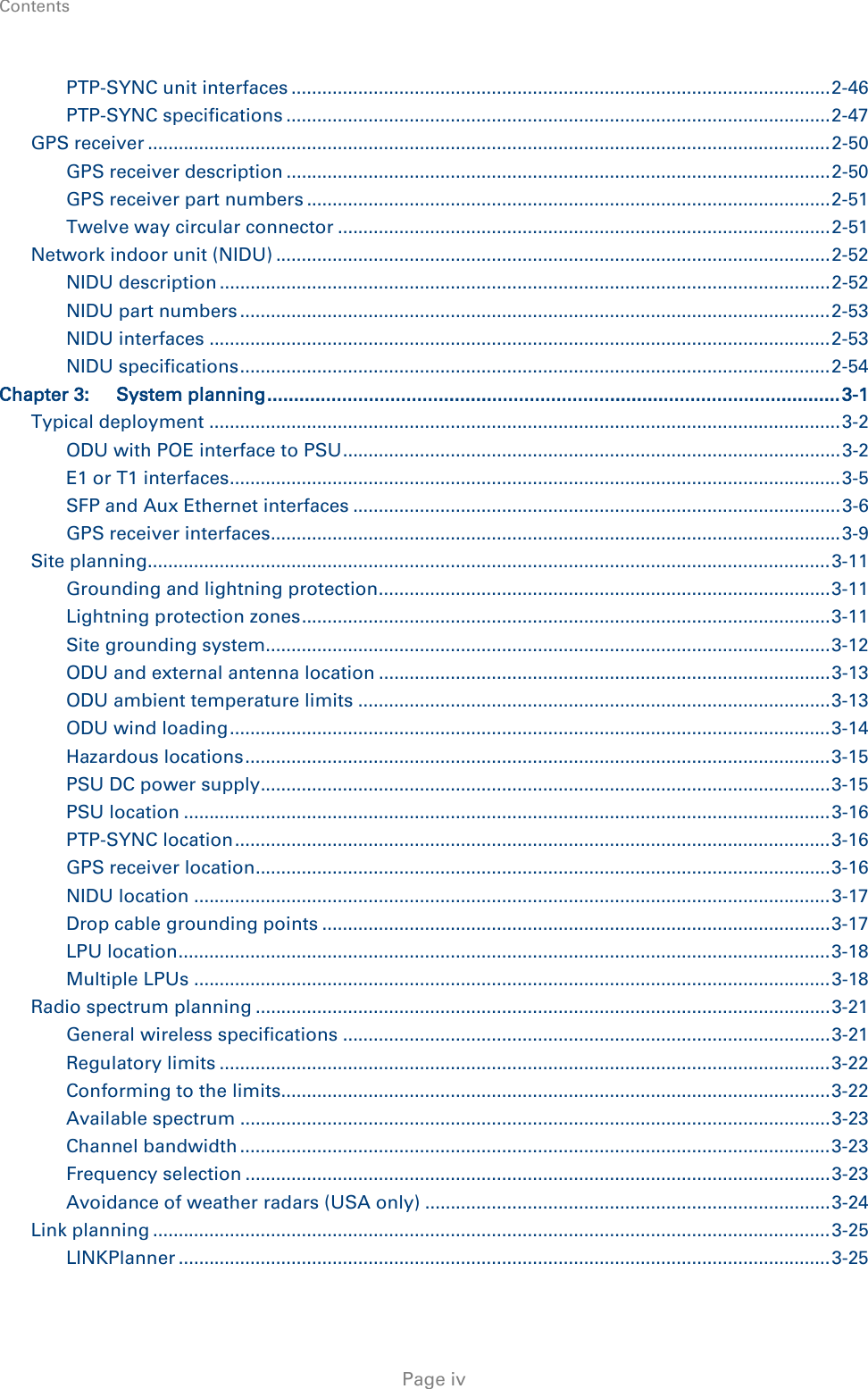

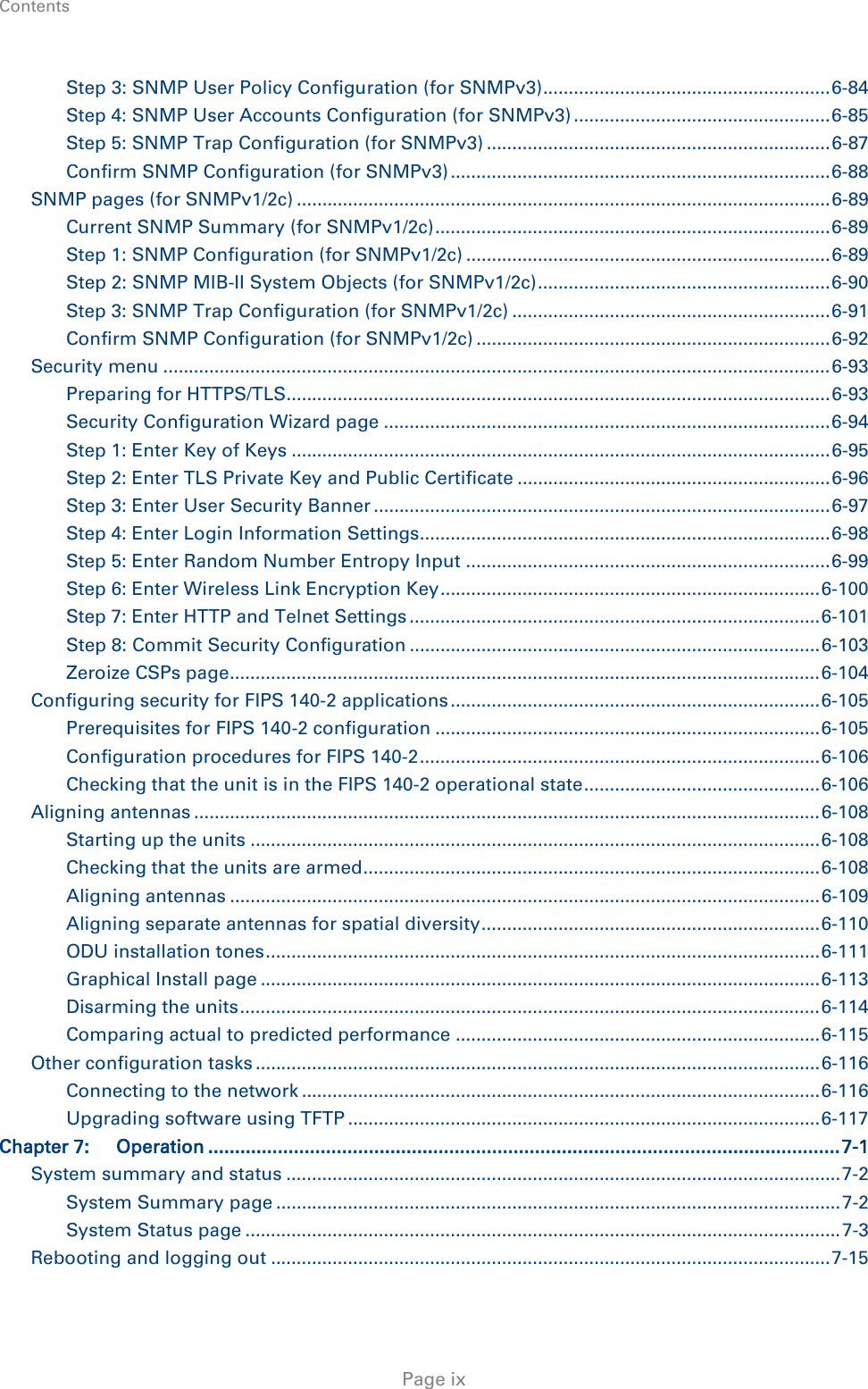
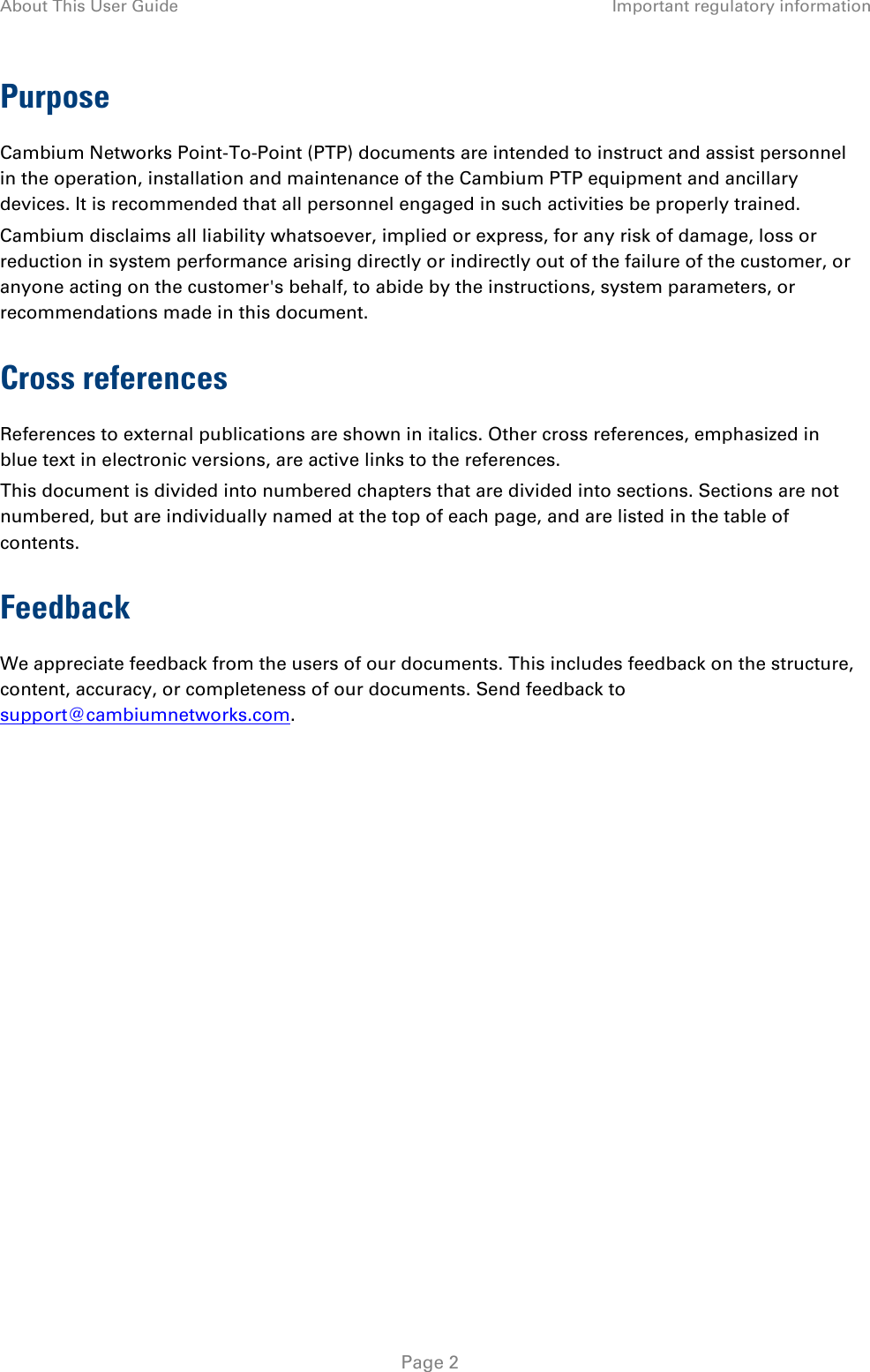


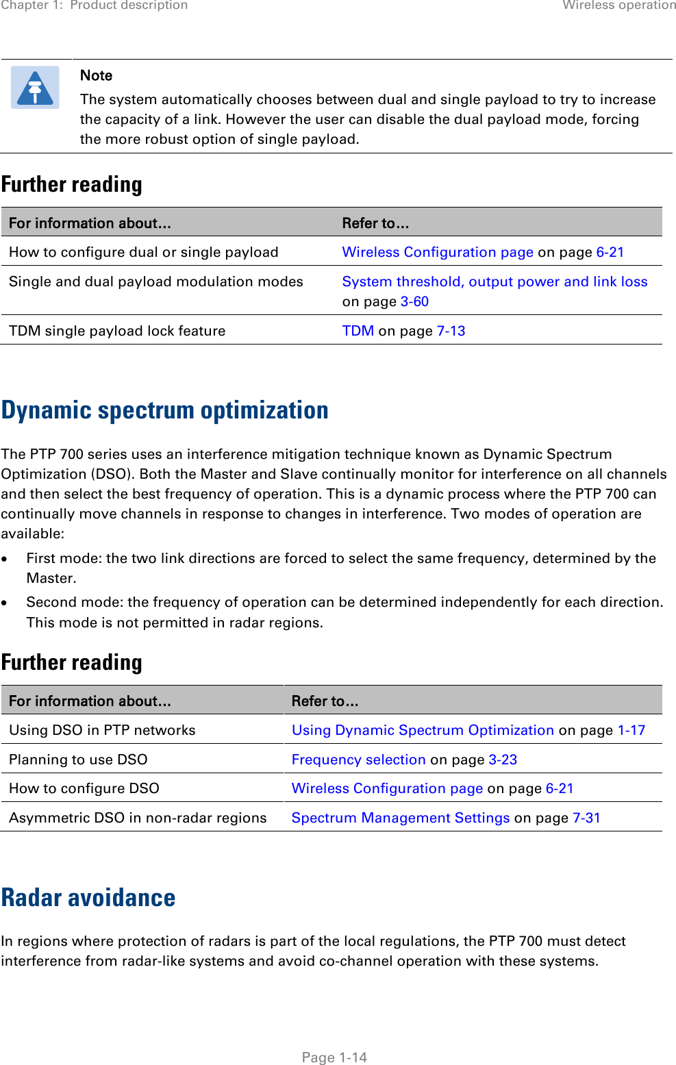
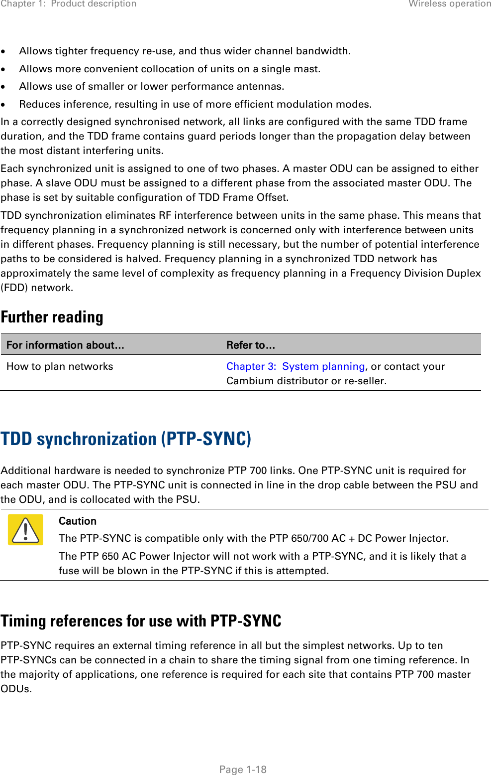
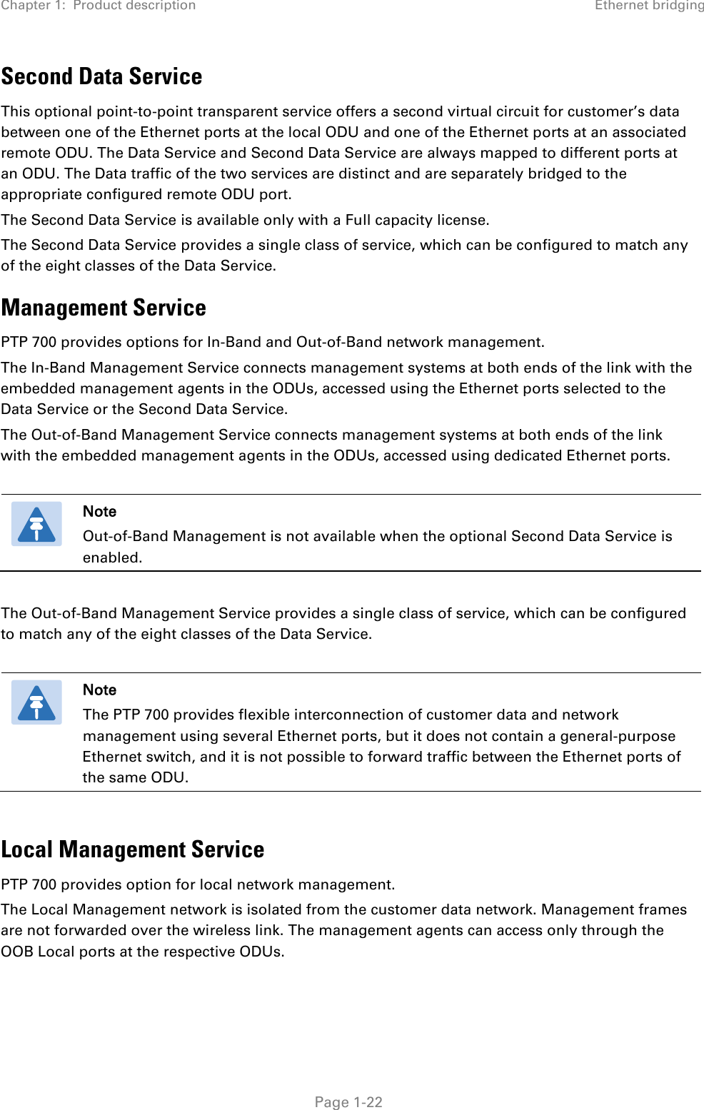
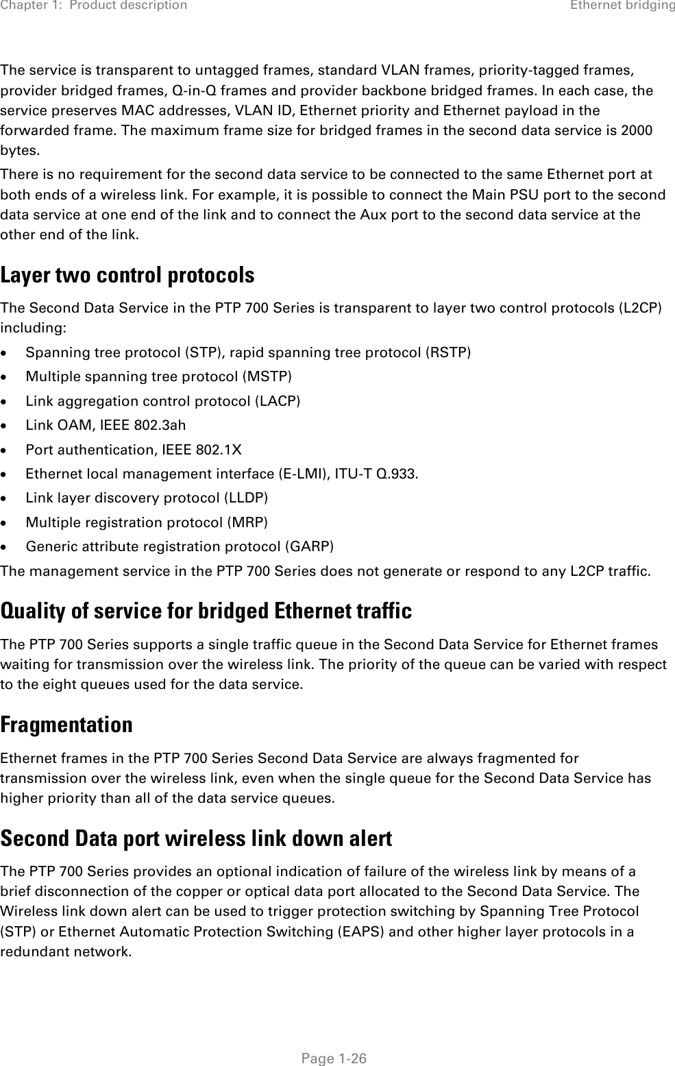
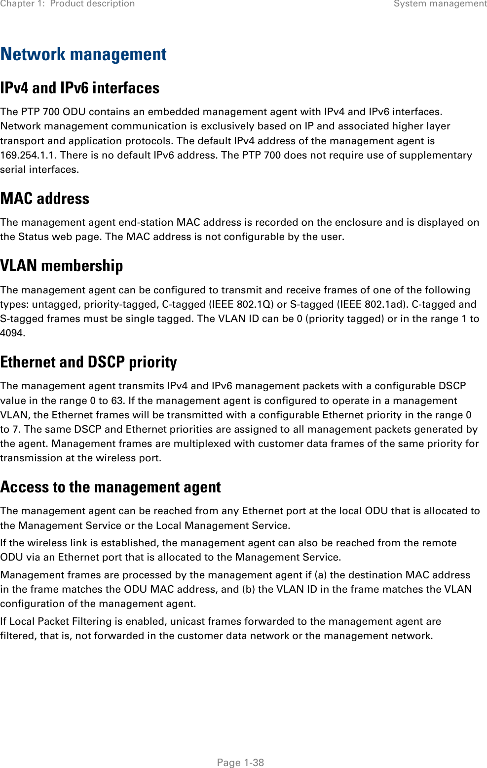
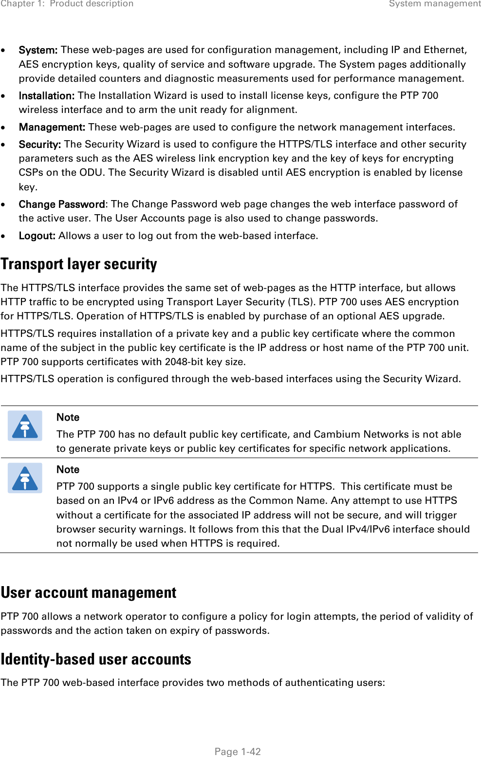
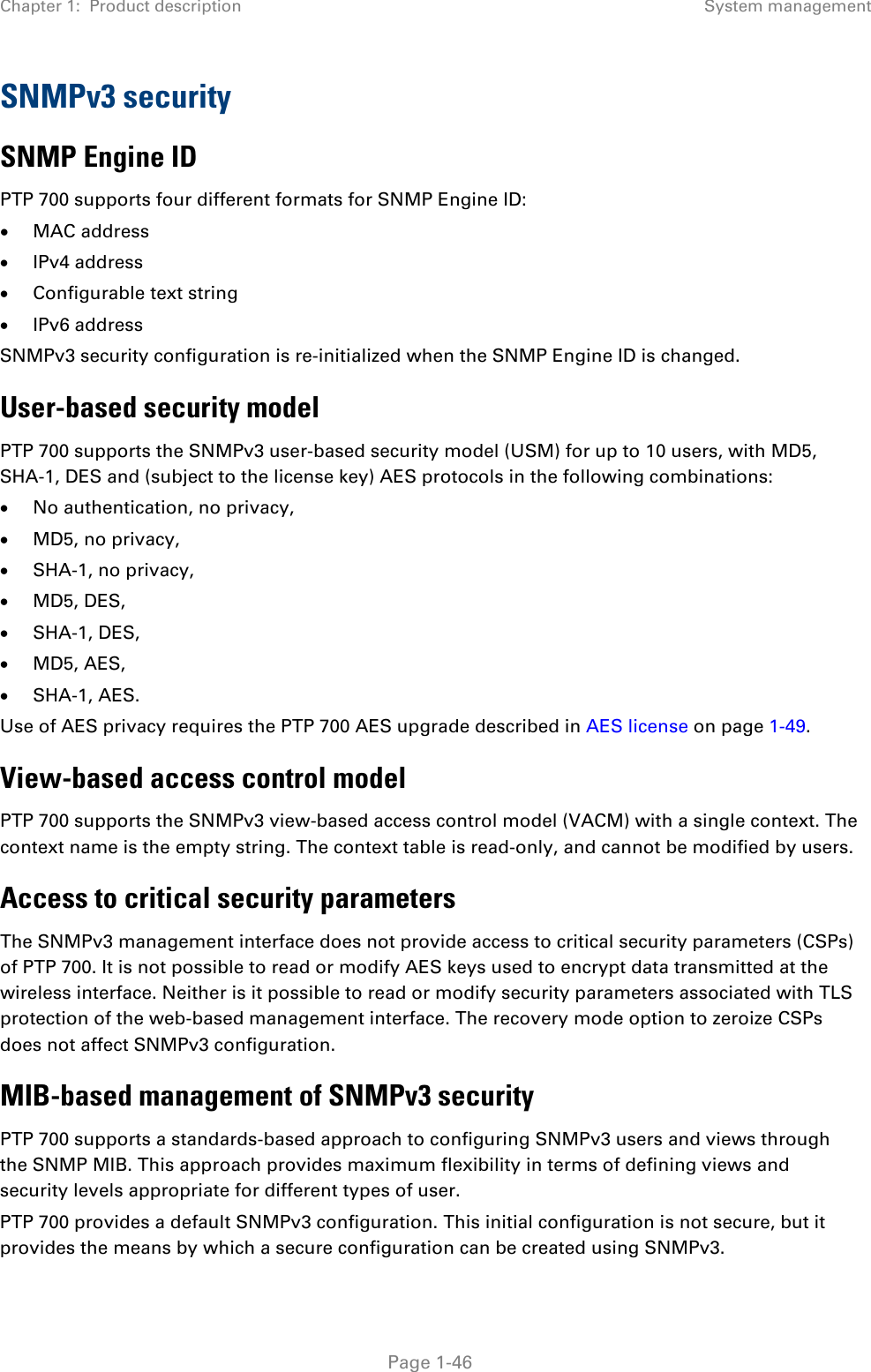
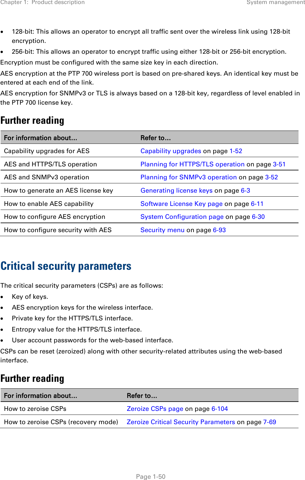
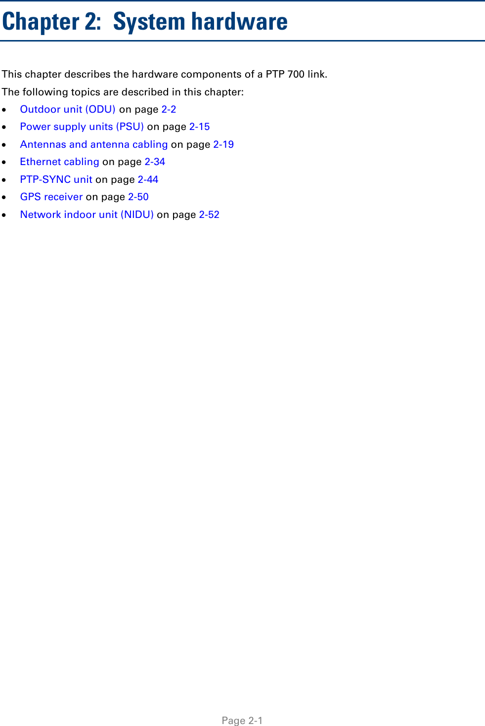


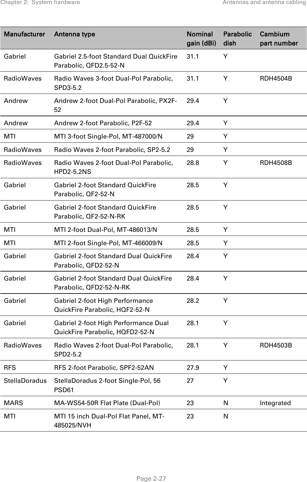
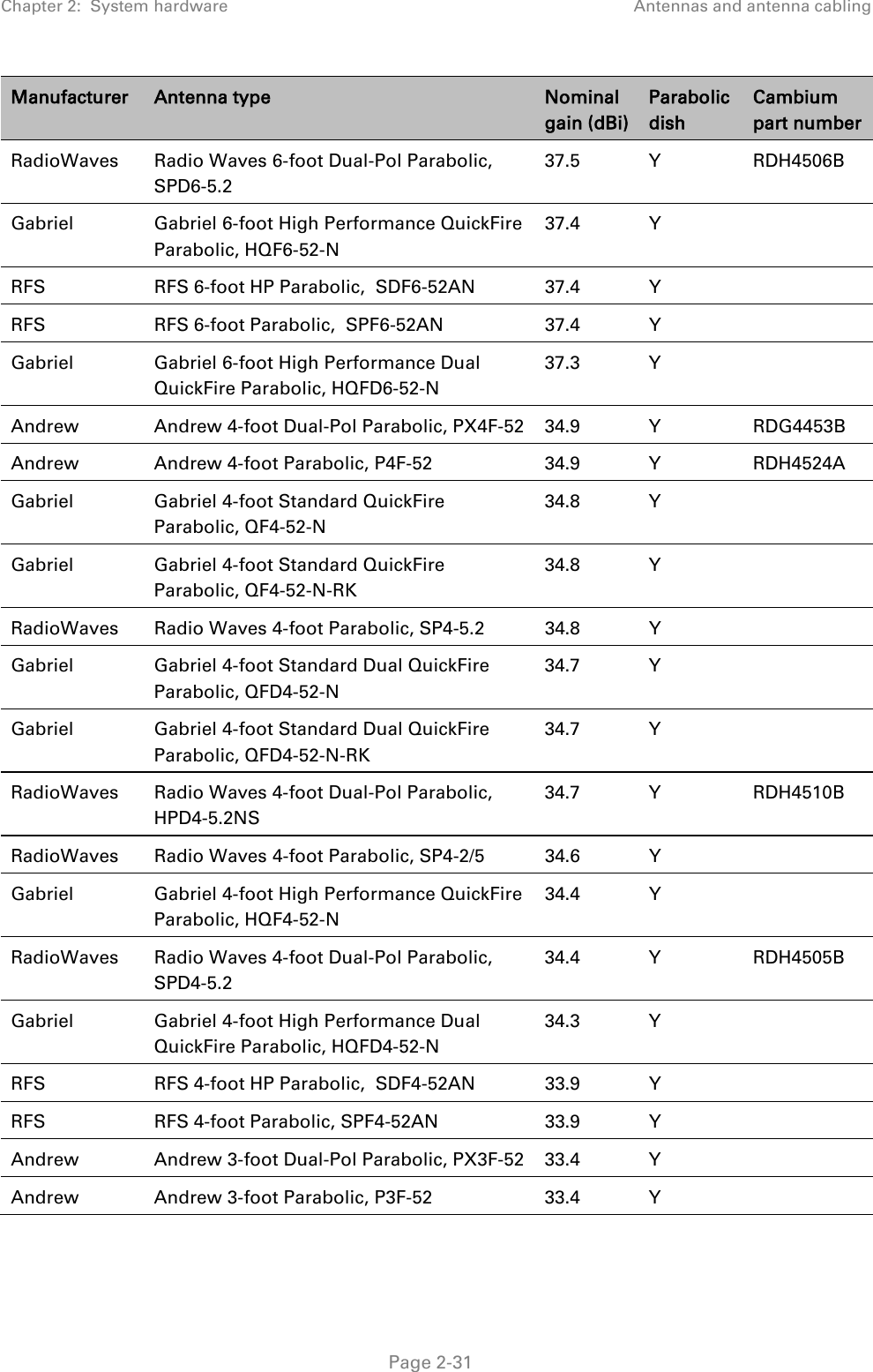


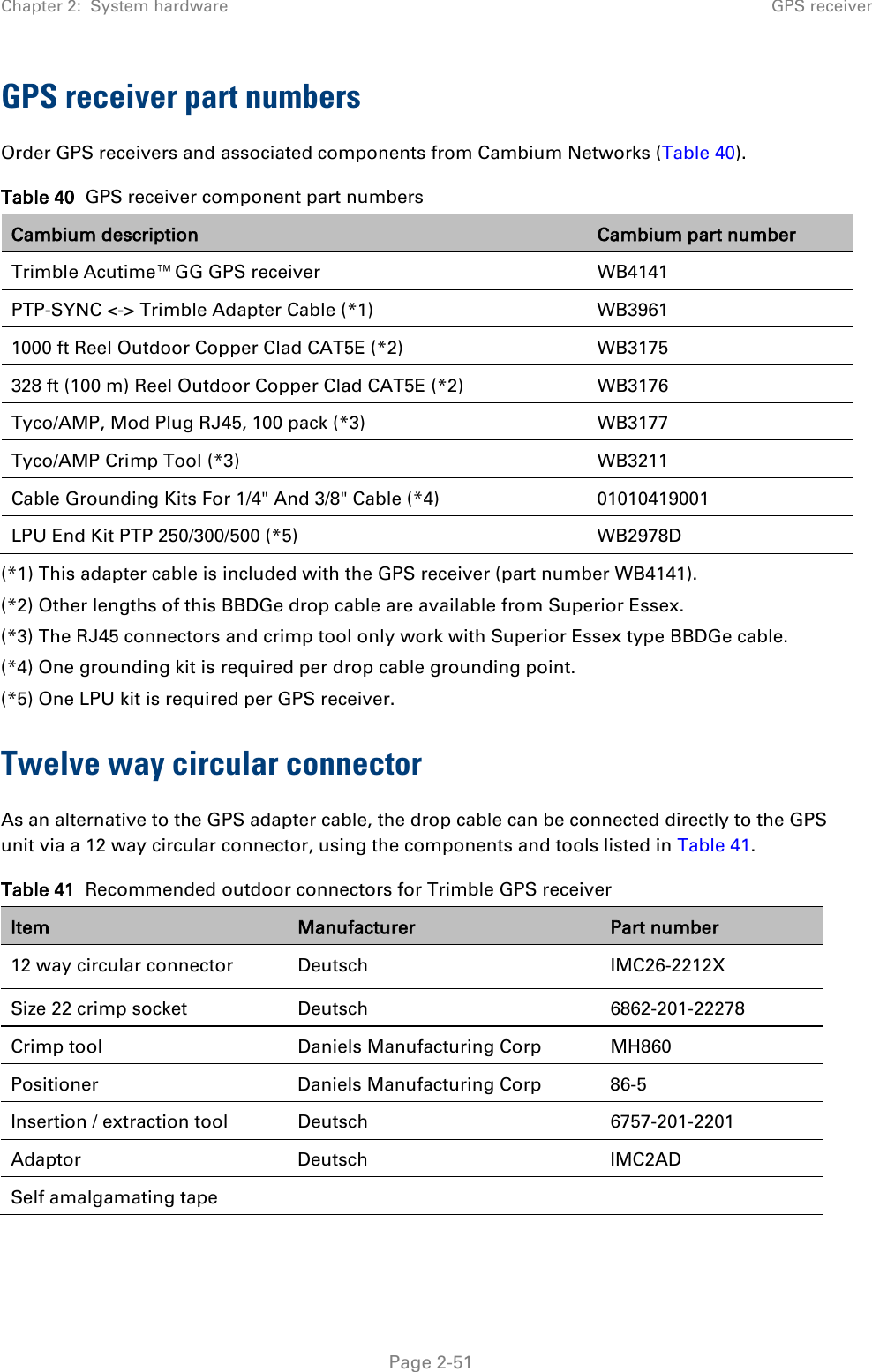

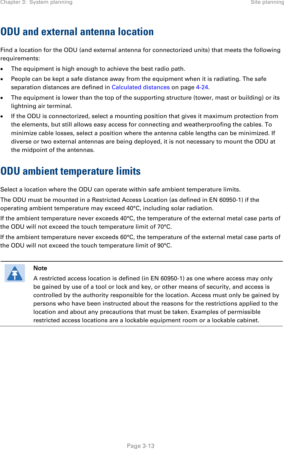

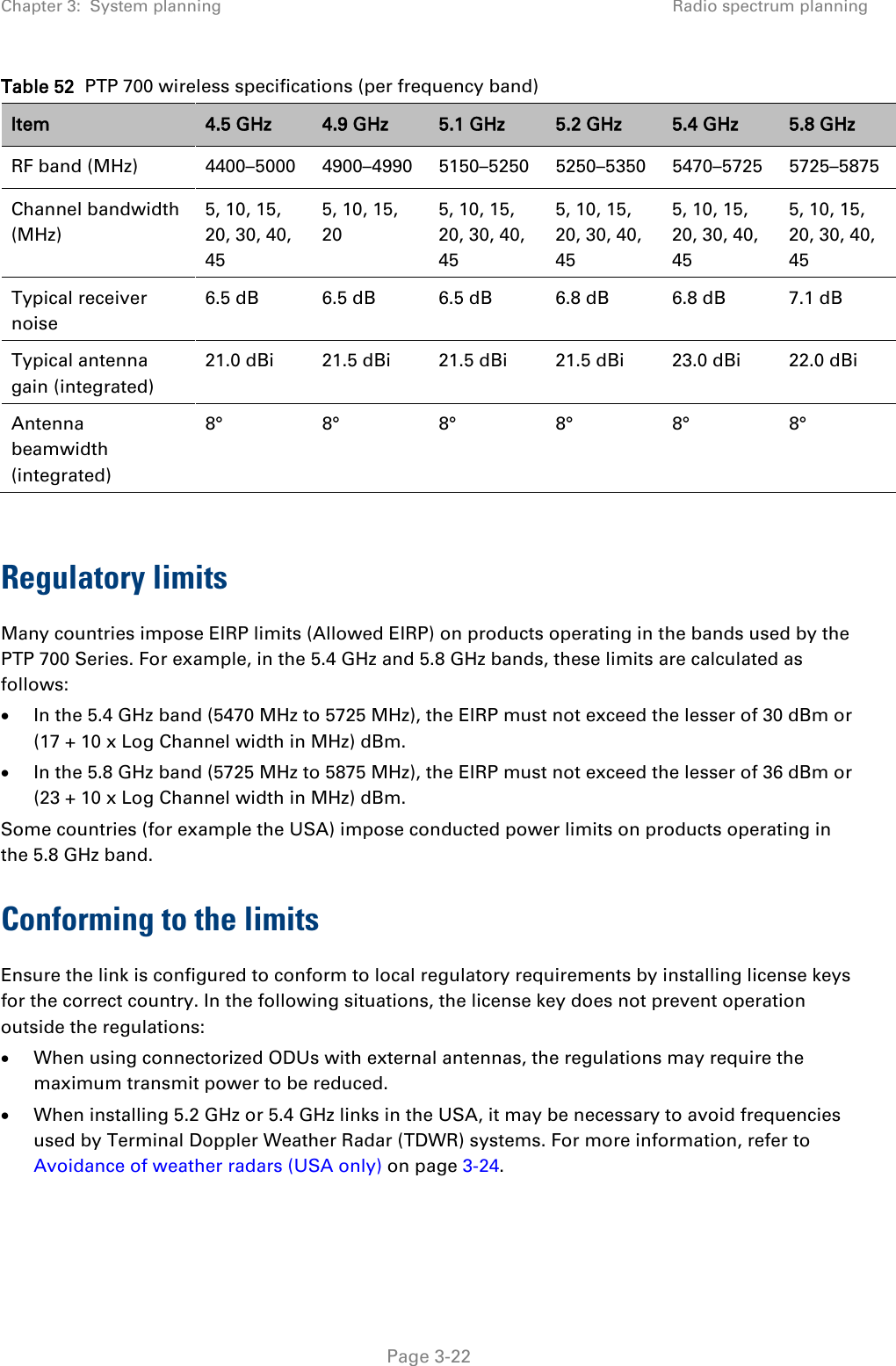

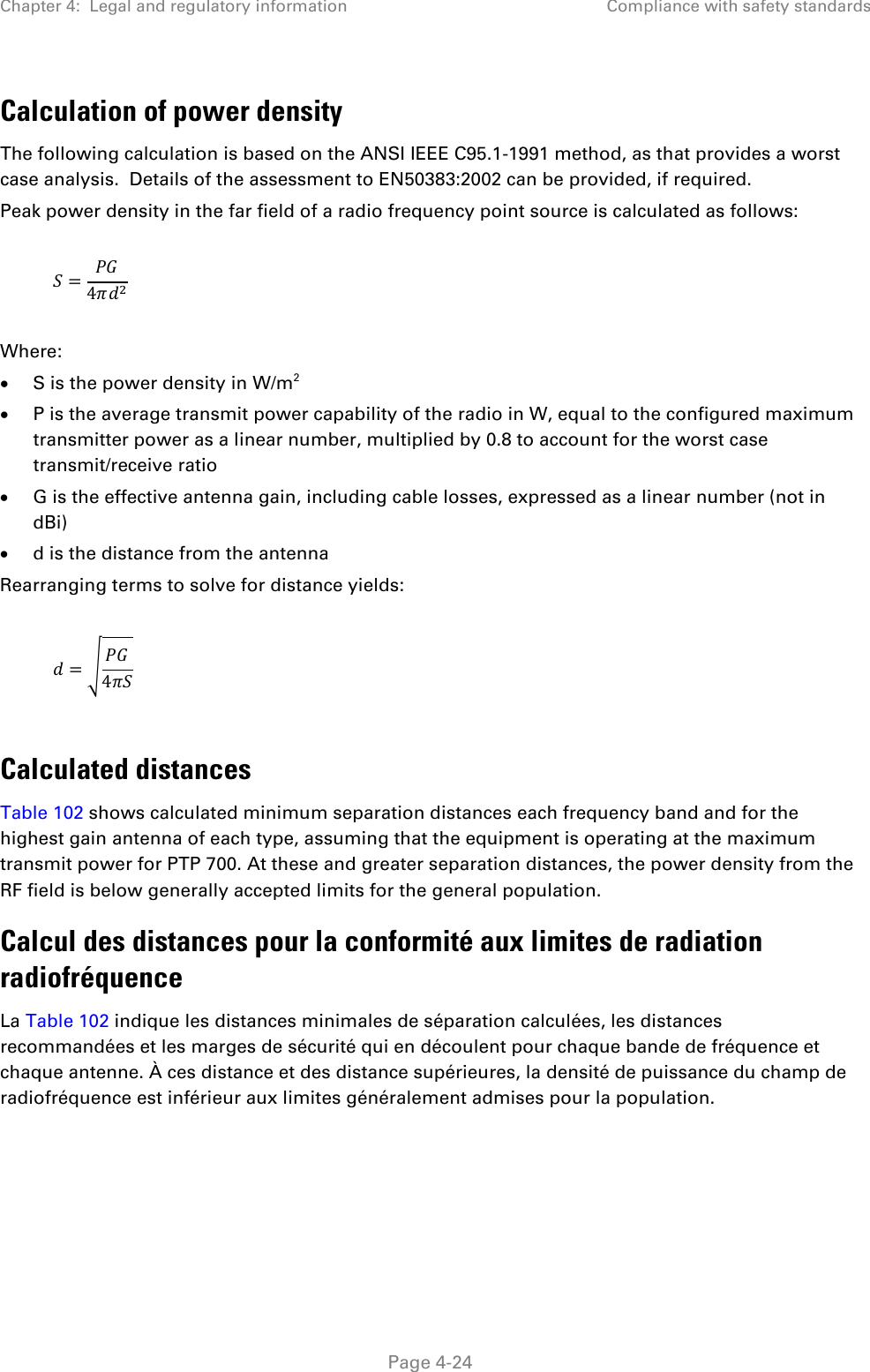
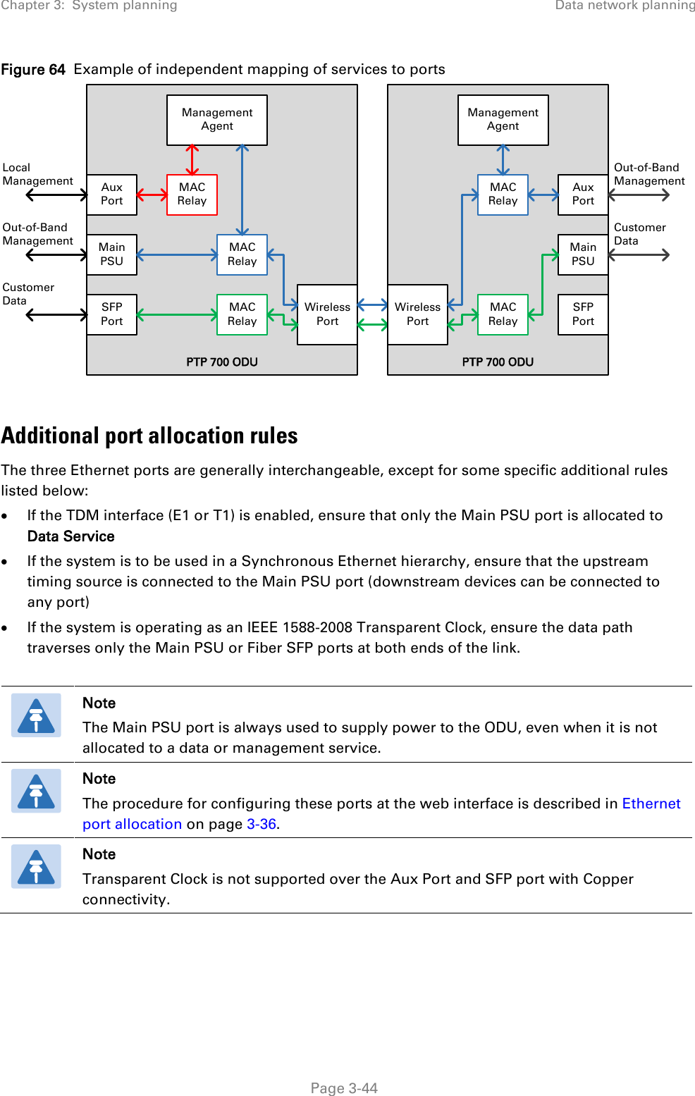
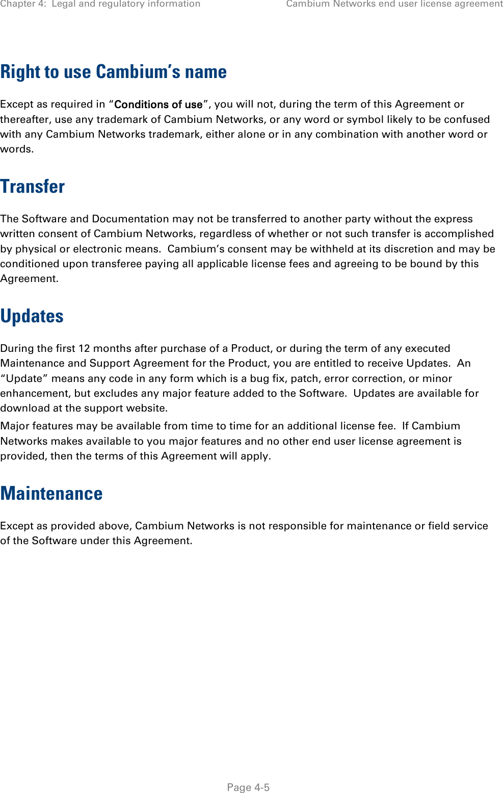
![Chapter 3: System planning Data network planning Table 57 Combinations of services with optional Local Management Service combination Data + Local Management + [Local Management] Data + In-Band Management + [Local Management] + [Local Management] Data + Out-of-Band Management + [Local Management] Data + Second Data + In-Band Management (with Data) + [Local Management] Data + Second Data + In-Band Management (with Second Data) + [Local Management] Data + Second Data + Local Management Ensure that the same service combination from Table 57 is used at both ends of the link. Warning Take care to avoid selecting different combinations of services at the two ends of the link. Mapping services to physical Ethernet ports In general, the three physical Ethernet ports (Main PSU, Aux and SFP) are interchangeable. Allowing for the freedom to choose the physical Ethernet ports, the six combinations in Table 57 give rise to a much larger number of different permutations (actually 63 of them). There is no objection to mapping the services to different physical ports at the two ends of the link, providing that the same row of Table 57 is used at each end. For example, Figure 64 shows a link where the combination of services is from the third row of Table 57. Local Management is provided at one end only. The Management Service maps the Main PSU Port at one end and the Aux Port at the other end. The Data Service maps to the SFP Port at one end of the link and to the Main PSU Port at the other end of the link. Note SFP will only be shown as an option when SFP Port Support is enabled via the licence key. Page 3-43](https://usermanual.wiki/Cambium-Networks/45700.Installation-Guide-Part-1/User-Guide-2625257-Page-178.png)

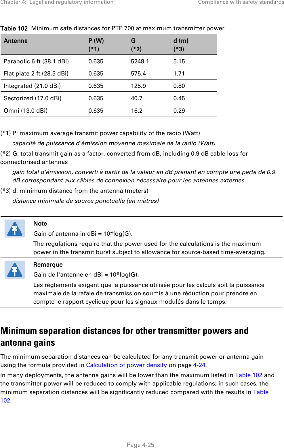
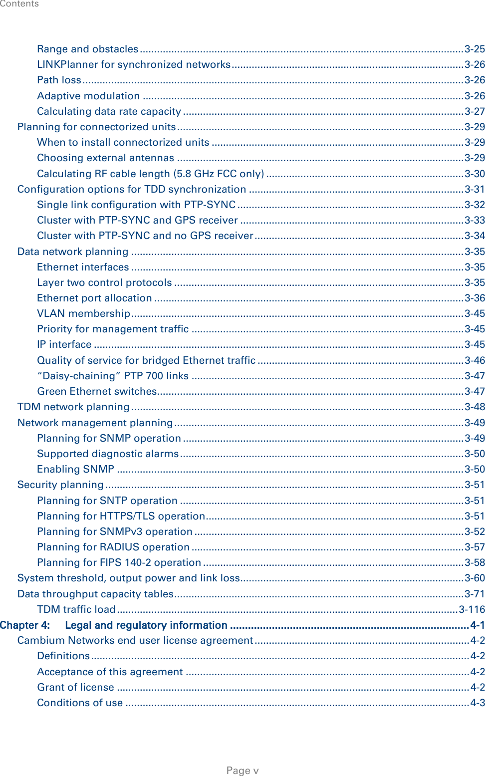
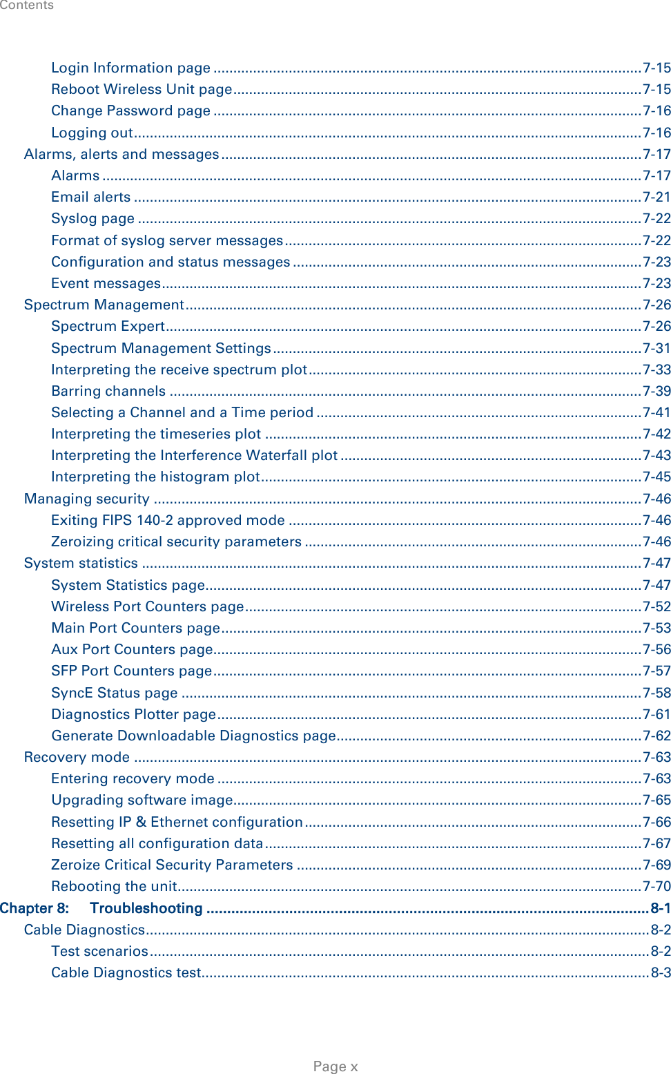
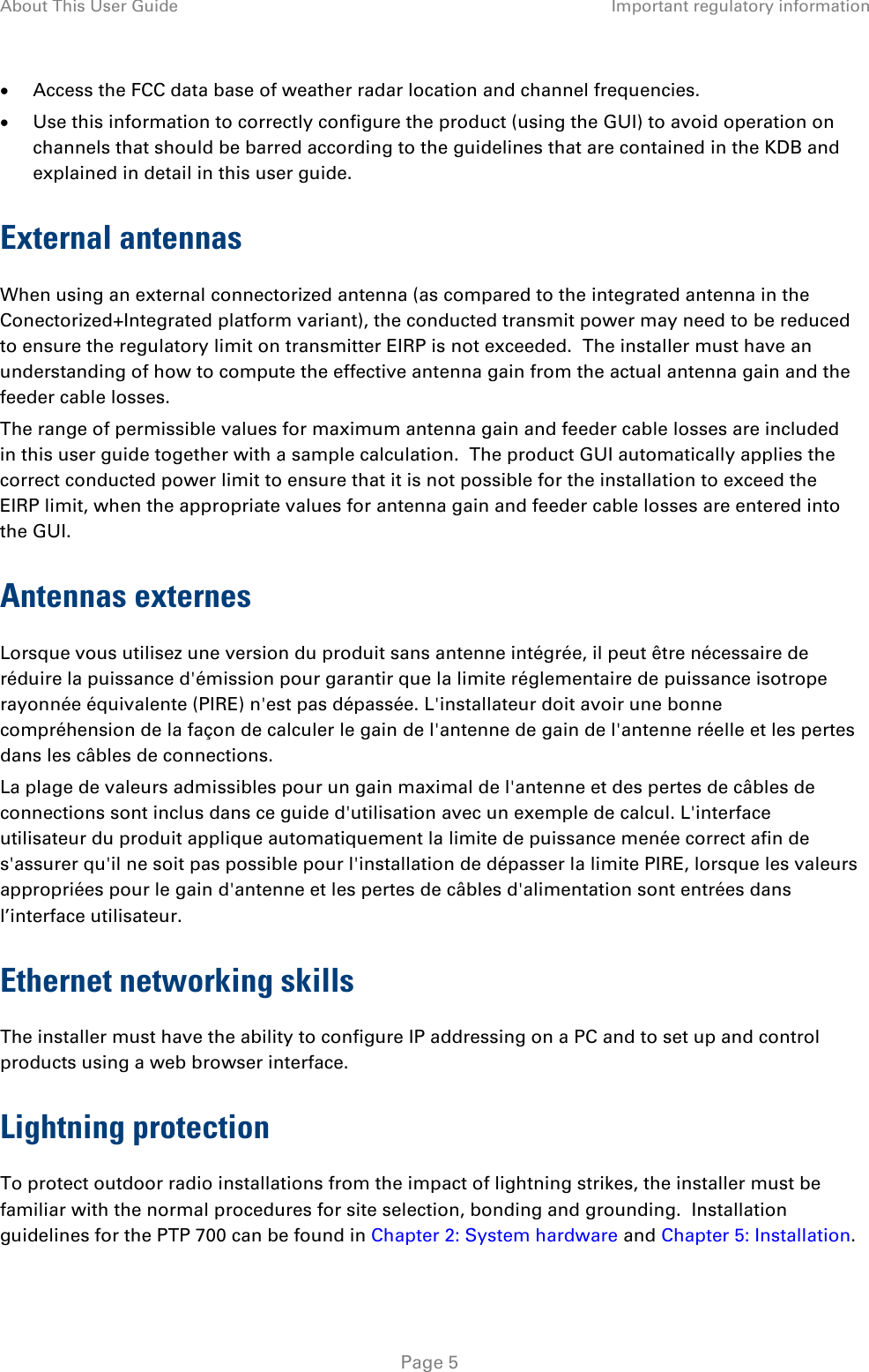
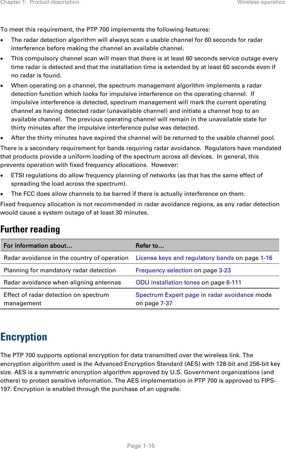
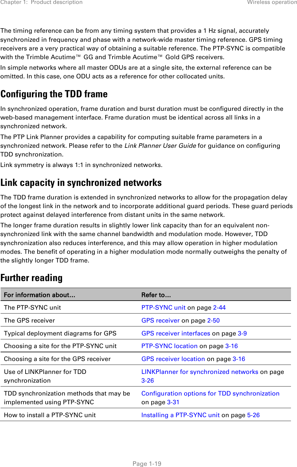
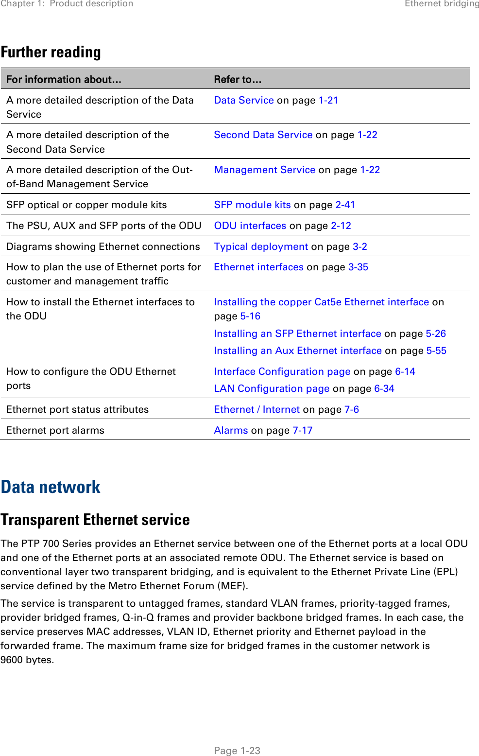
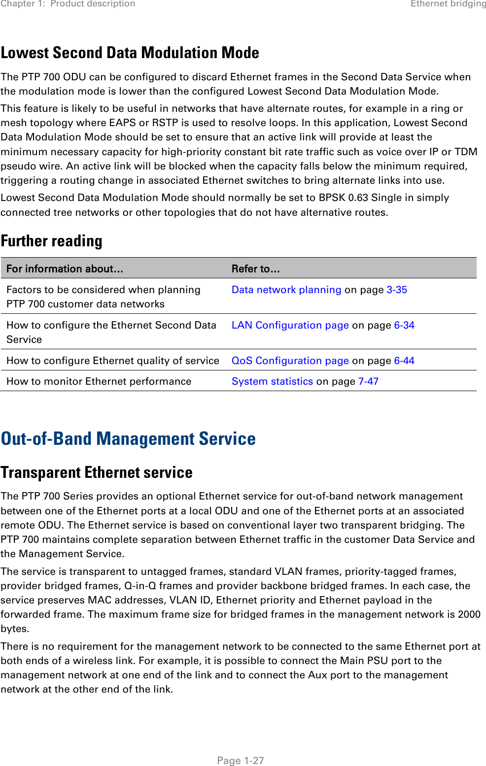
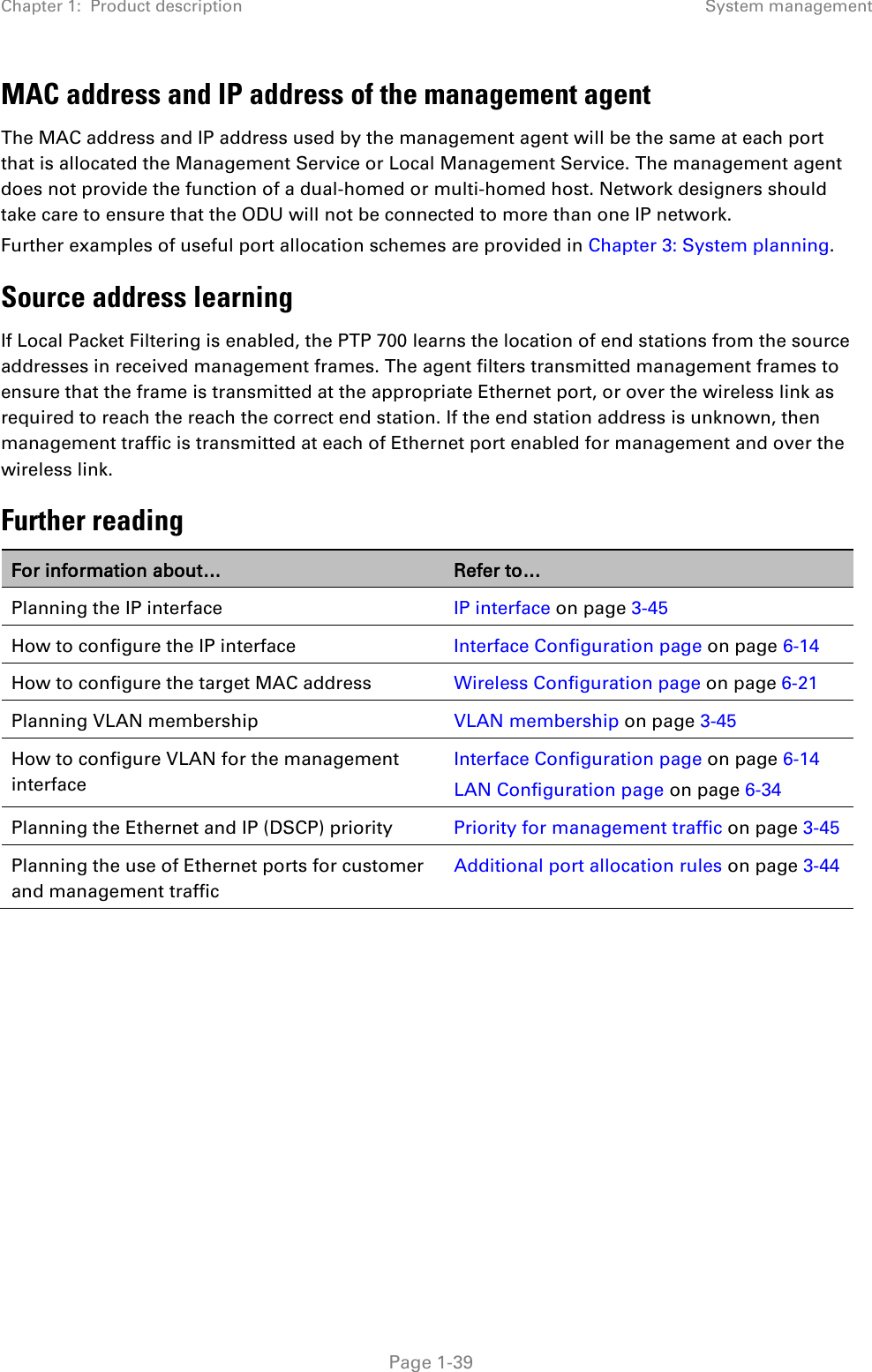
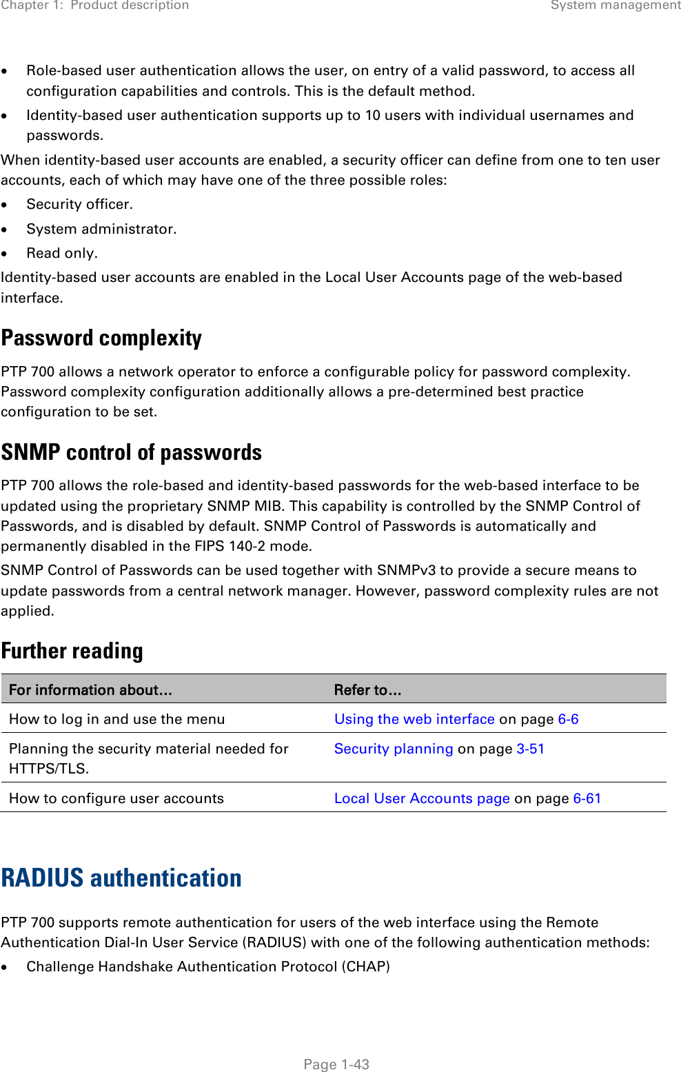
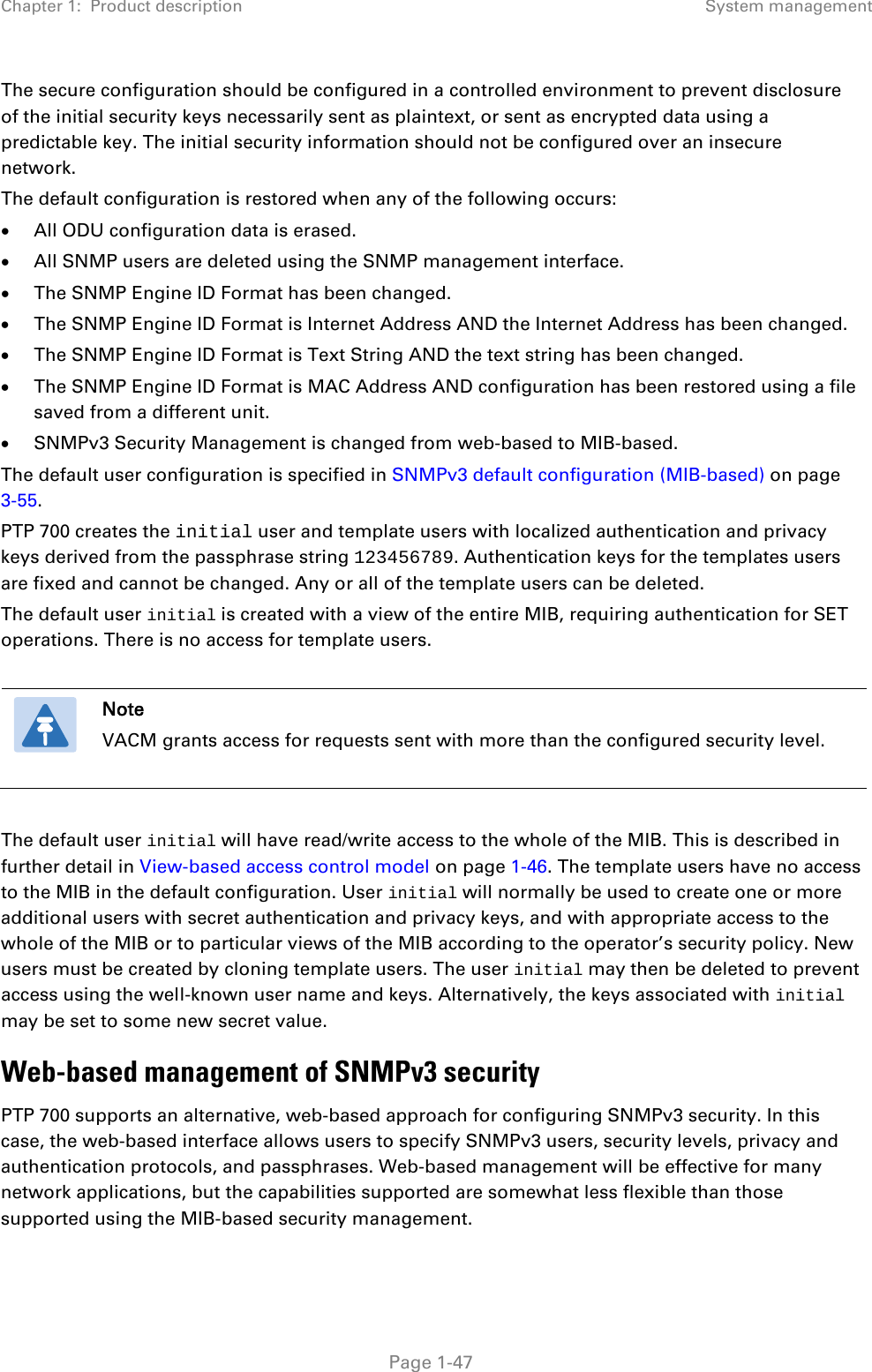
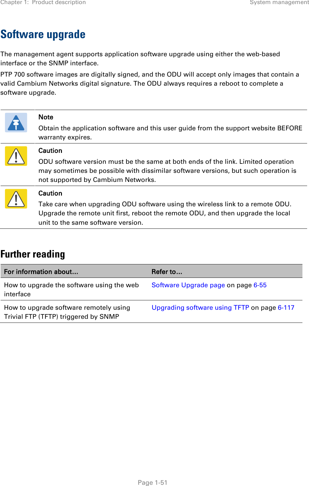
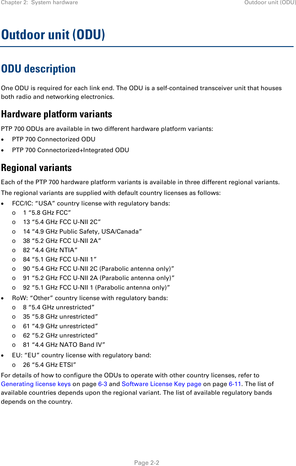
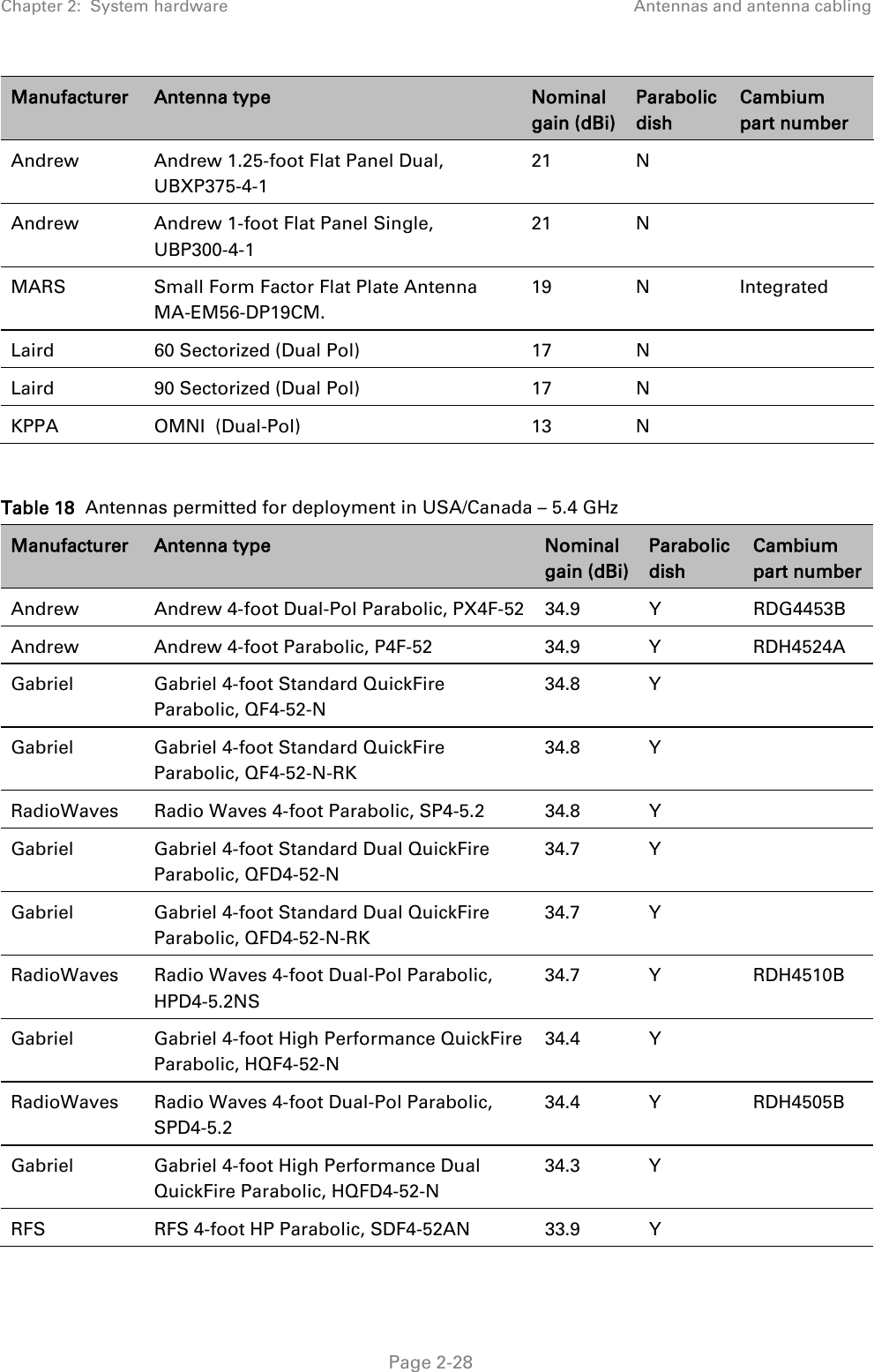
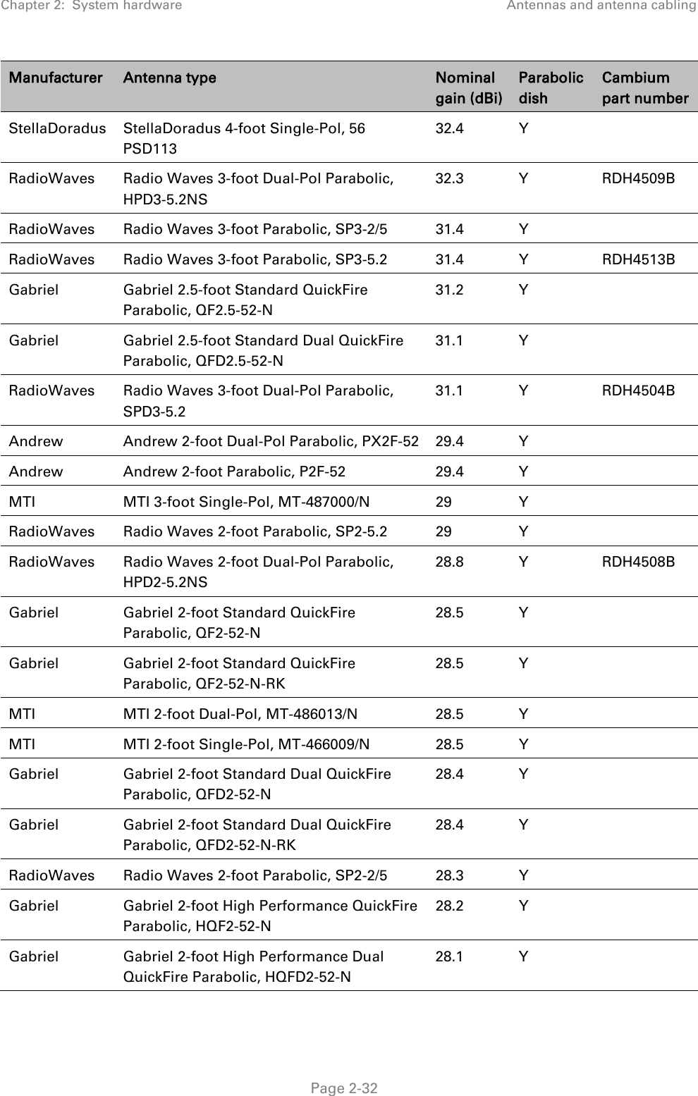
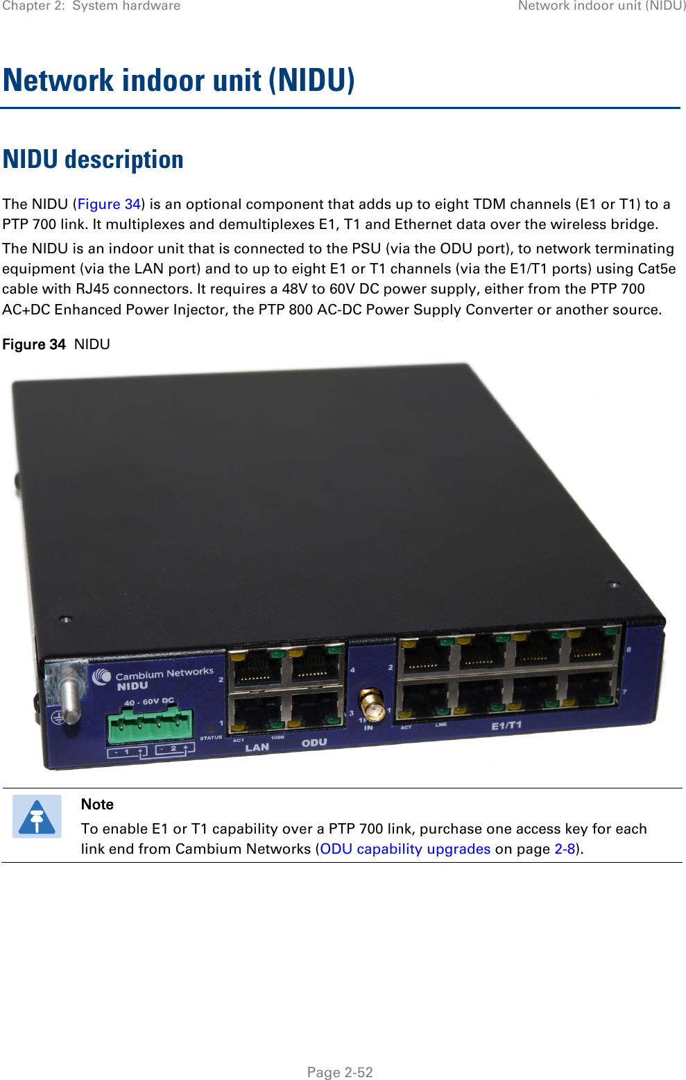
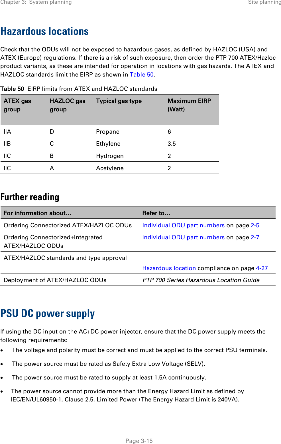
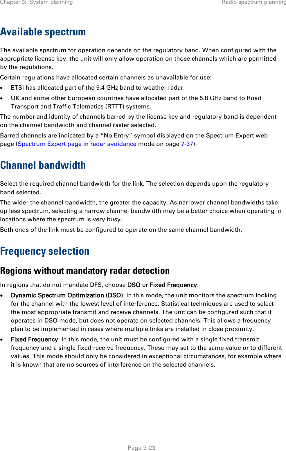
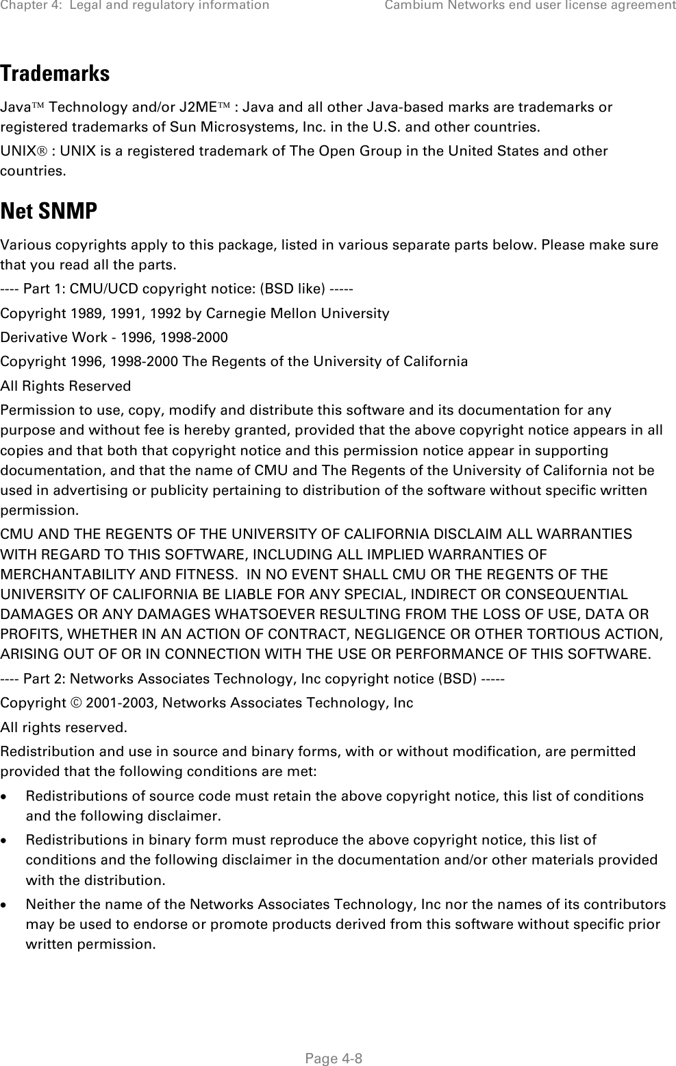
![Chapter 3: System planning Security planning Table 60 Permitted character set for SNMPv3 passphrases Character Code Character Code <space> 32 ; 59 ! 33 < 60 “ 34 = 61 # 35 > 62 $ 36 ? 63 % 37 @ 64 & 38 A..Z 65..90 ' 39 [ 91 ( 40 \ 92 ) 41 ] 93 * 42 ^ 94 + 43 _ 95 , 44 ` 96 - 45 a..z 97..122 . 46 { 123 / 47 | 124 0..9 48..57 } 125 : 58 ~ 126 Identify up to two SNMP users that will be configured to receive notifications (traps). Identify the Internet address (IPv4 or IPv6) and UDP port number of the associated SNMP manager. Page 3-54](https://usermanual.wiki/Cambium-Networks/45700.Installation-Guide-Part-1/User-Guide-2625257-Page-189.png)


![Chapter 4: Legal and regulatory information Cambium Networks end user license agreement The license and distribution terms for any publically available version or derivative of this code cannot be changed. i.e. this code cannot simply be copied and put under another distribution license [including the GNU Public License.] Zlib Copyright © 1995-2005 Jean-loup Gailly and Mark Adler This software is provided ‘as-is’, without any express or implied warranty. In no event will the authors be held liable for any damages arising from the use of this software. Permission is granted to anyone to use this software for any purpose, including commercial applications, and to alter it and redistribute it freely, subject to the following restrictions: 1. The origin of this software must not be misrepresented; you must not claim that you wrote the original software. If you use this software in a product, an acknowledgment in the product documentation would be appreciated but is not required. 2. Altered source versions must be plainly marked as such, and must not be misrepresented as being the original software. 3. This notice may not be removed or altered from any source distribution. Jean-loup Gailly jloup@gzip.org Mark Adler madler@alumni.caltech.edu Libpng libpng versions 1.2.6, August 15, 2004, through 1.2.35, February 14, 2009, are Copyright © 2004, 2006-2008 Glenn Randers-Pehrson, and are distributed according to the same disclaimer and license as libpng-1.2.5 with the following individual added to the list of Contributing Authors Cosmin Truta libpng versions 1.0.7, July 1, 2000, through 1.2.5 - October 3, 2002, are Copyright © 2000-2002 Glenn Randers-Pehrson, and are distributed according to the same disclaimer and license as libpng-1.0.6 with the following individuals added to the list of Contributing Authors Simon-Pierre Cadieux Eric S. Raymond Gilles Vollant and with the following additions to the disclaimer: There is no warranty against interference with your enjoyment of the library or against infringement. There is no warranty that our efforts or the library will fulfil any of your particular purposes or needs. This library is provided with all faults, and the entire risk of satisfactory quality, performance, accuracy, and effort is with the user. libpng versions 0.97, January 1998, through 1.0.6, March 20, 2000, are Copyright © 1998, 1999 Glenn Randers-Pehrson, and are distributed according to the same disclaimer and license as libpng-0.96, with the following individuals added to the list of Contributing Authors: Tom Lane Glenn Randers-Pehrson Page 4-14](https://usermanual.wiki/Cambium-Networks/45700.Installation-Guide-Part-1/User-Guide-2625257-Page-266.png)


![Chapter 4: Legal and regulatory information Cambium Networks end user license agreement or other liability obligations and/or rights consistent with this License. However, in accepting such obligations, You may act only on Your own behalf and on Your sole responsibility, not on behalf of any other Contributor, and only if You agree to indemnify, defend, and hold each Contributor harmless for any liability incurred by, or claims asserted against, such Contributor by reason of your accepting any such warranty or additional liability. END OF TERMS AND CONDITIONS APPENDIX: How to apply the Apache License to your work. To apply the Apache License to your work, attach the following boilerplate notice, with the fields enclosed by brackets "[]" replaced with your own identifying information. (Don't include the brackets!) The text should be enclosed in the appropriate comment syntax for the file format. We also recommend that a file or class name and description of purpose be included on the same "printed page" as the copyright notice for easier identification within third-party archives. Copyright [yyyy] [name of copyright owner] Licensed under the Apache License, Version 2.0 (the "License"); you may not use this file except in compliance with the License. You may obtain a copy of the License at http://www.apache.org/licenses/LICENSE-2.0 Unless required by applicable law or agreed to in writing, software distributed under the License is distributed on an "AS IS" BASIS, WITHOUT WARRANTIES OR CONDITIONS OF ANY KIND, either express or implied. See the License for the specific language governing permissions and limitations under the License. Page 4-20](https://usermanual.wiki/Cambium-Networks/45700.Installation-Guide-Part-1/User-Guide-2625257-Page-272.png)