Cambium Networks 50650 Wireless Ethernet Bridge User Manual PTP 650 Series User Guide
Cambium Networks Limited Wireless Ethernet Bridge PTP 650 Series User Guide
UserManual.wiki
>
Cambium Networks
>
50650 User Manual
>
User Manual Part 1
Contents
1.
User Manual Part 1
2.
User Manual Part 2
3.
Installation Guide
4.
User Guide Part 1
5.
User Guide Part 2
6.
User Guide Part 3
User Manual Part 1
Navigation menu
Upload a User Manual
Namespaces
Wiki Guide
HTML
PDF
Info
Views
User Manual
Discussion / Help
Navigation

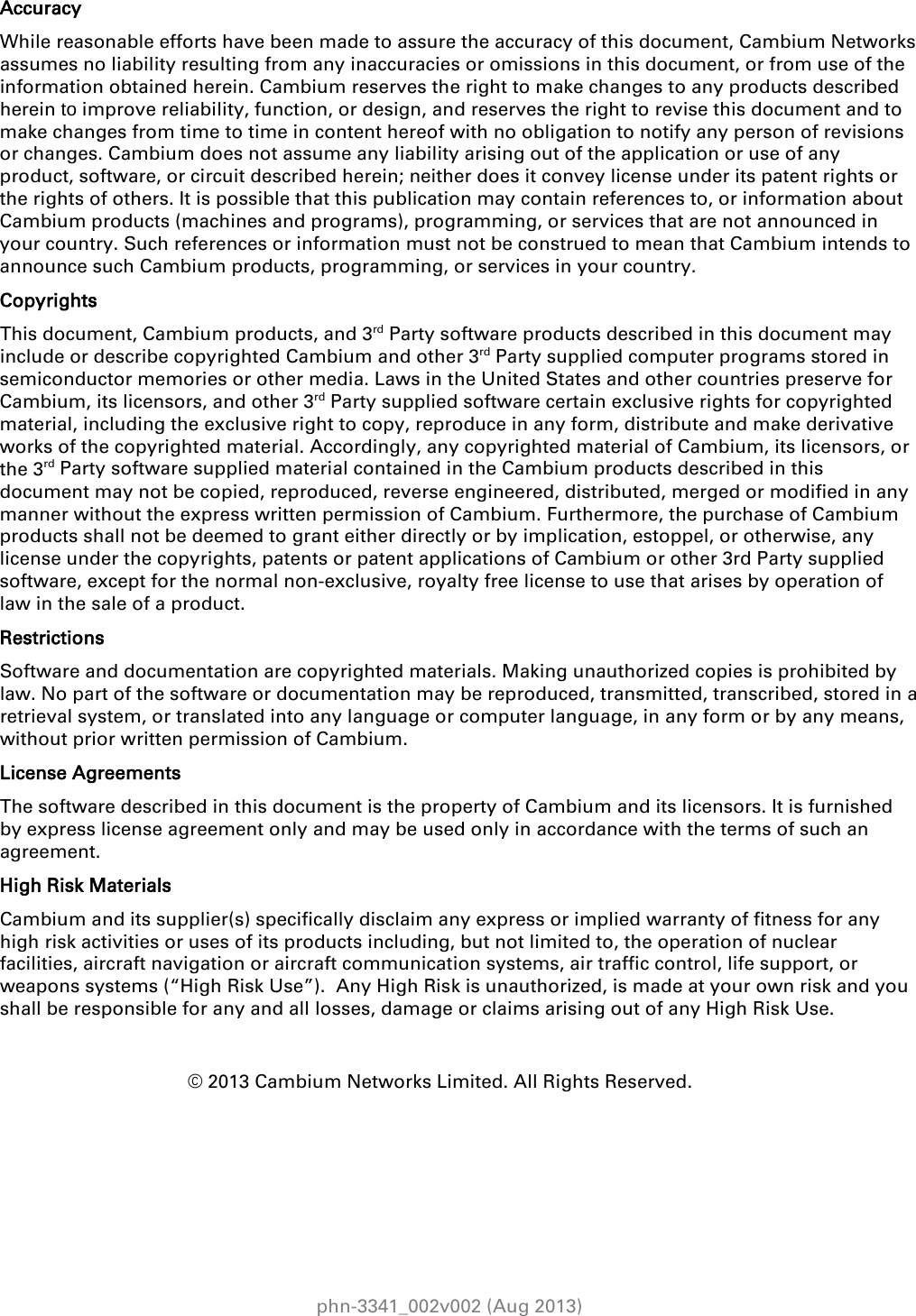

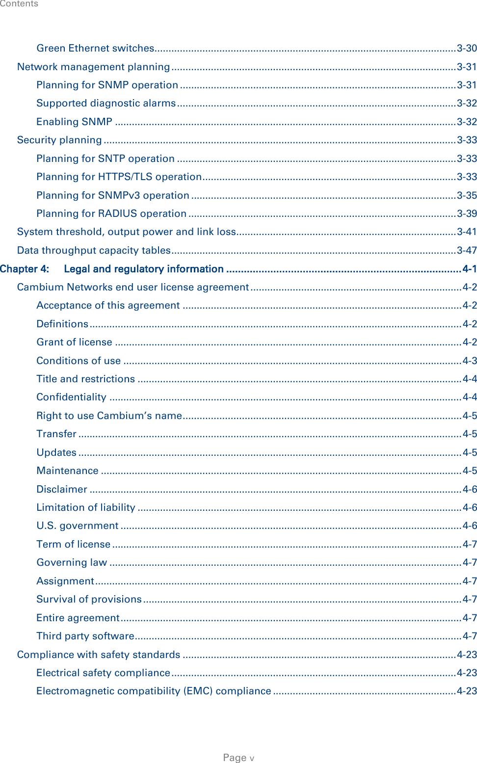


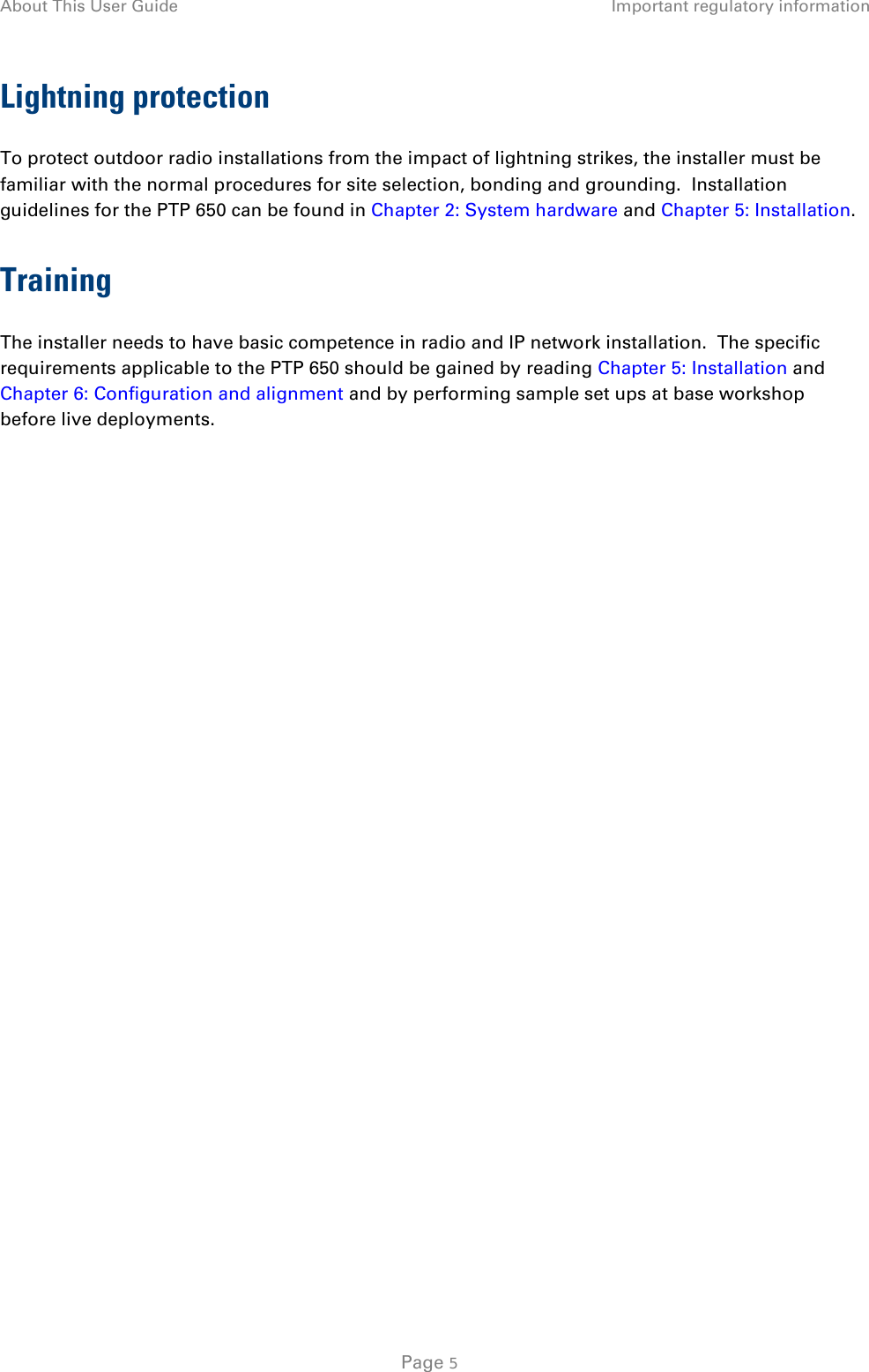

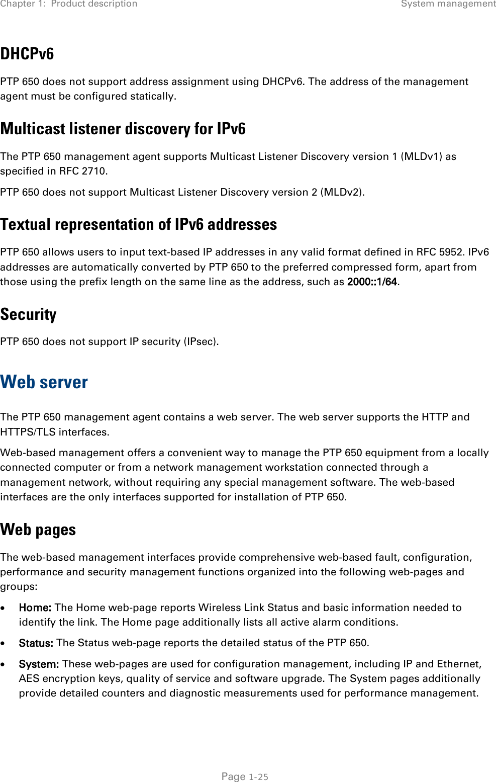
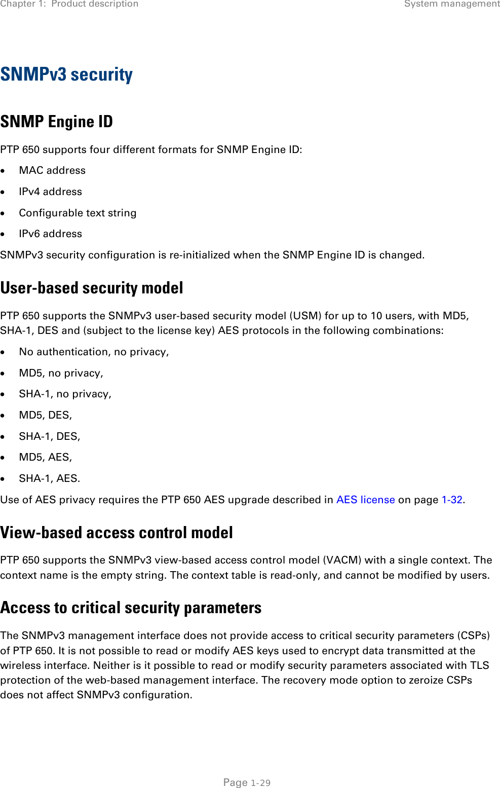


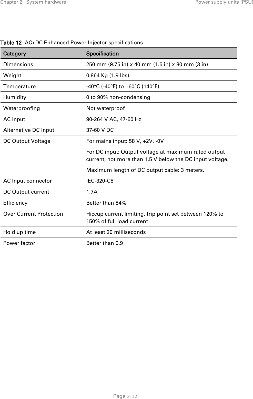


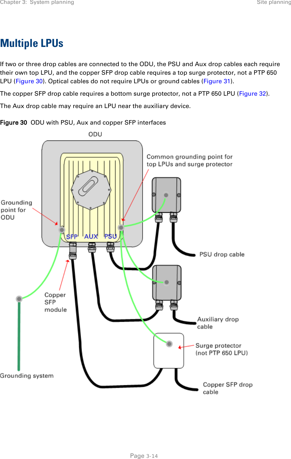
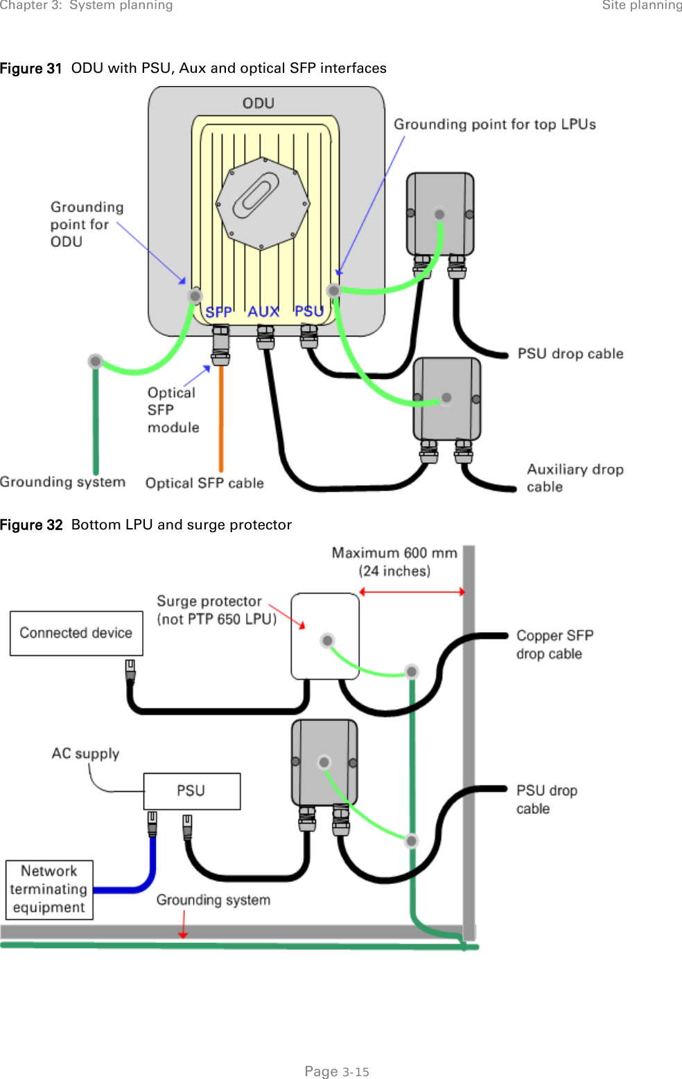
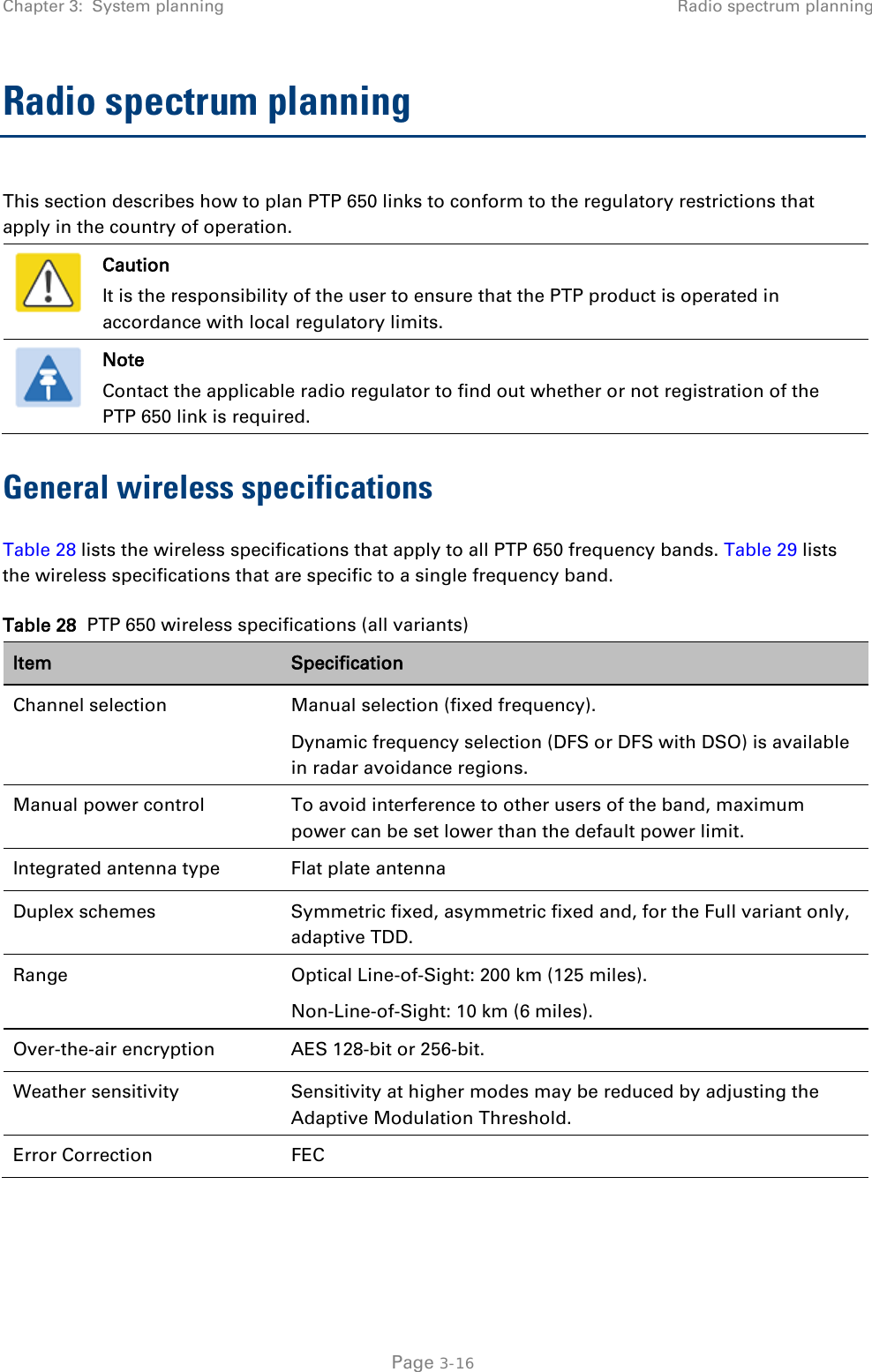
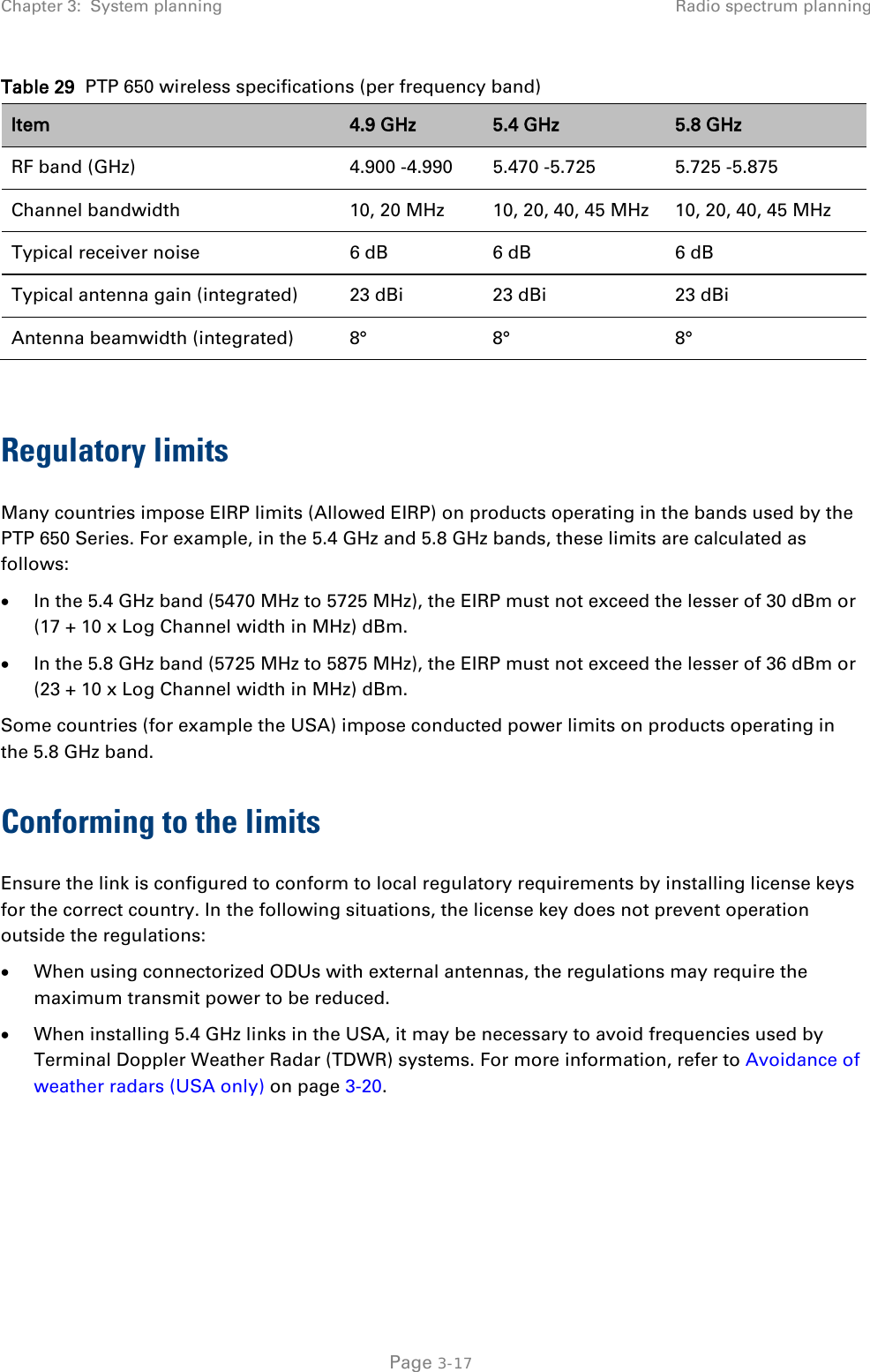
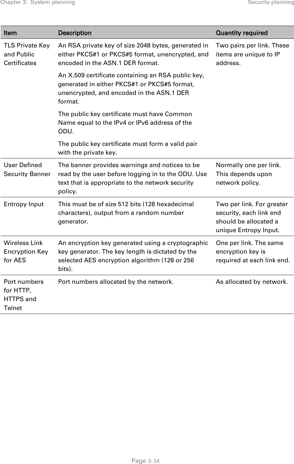
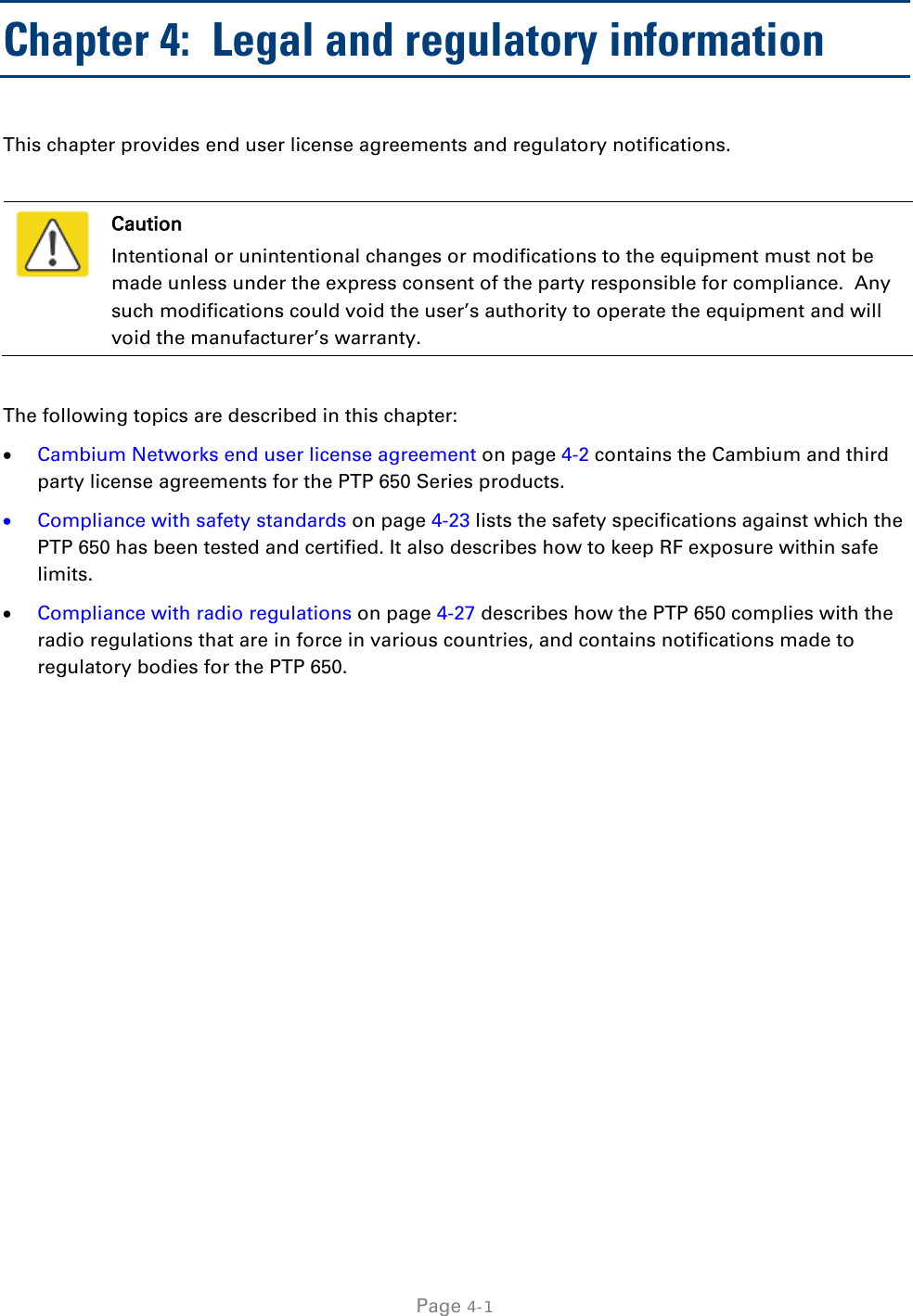
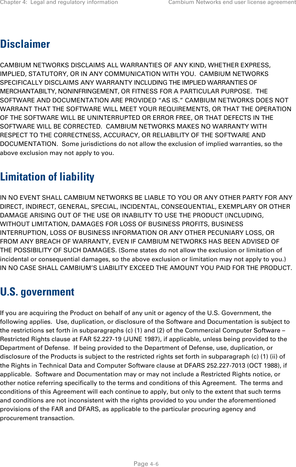
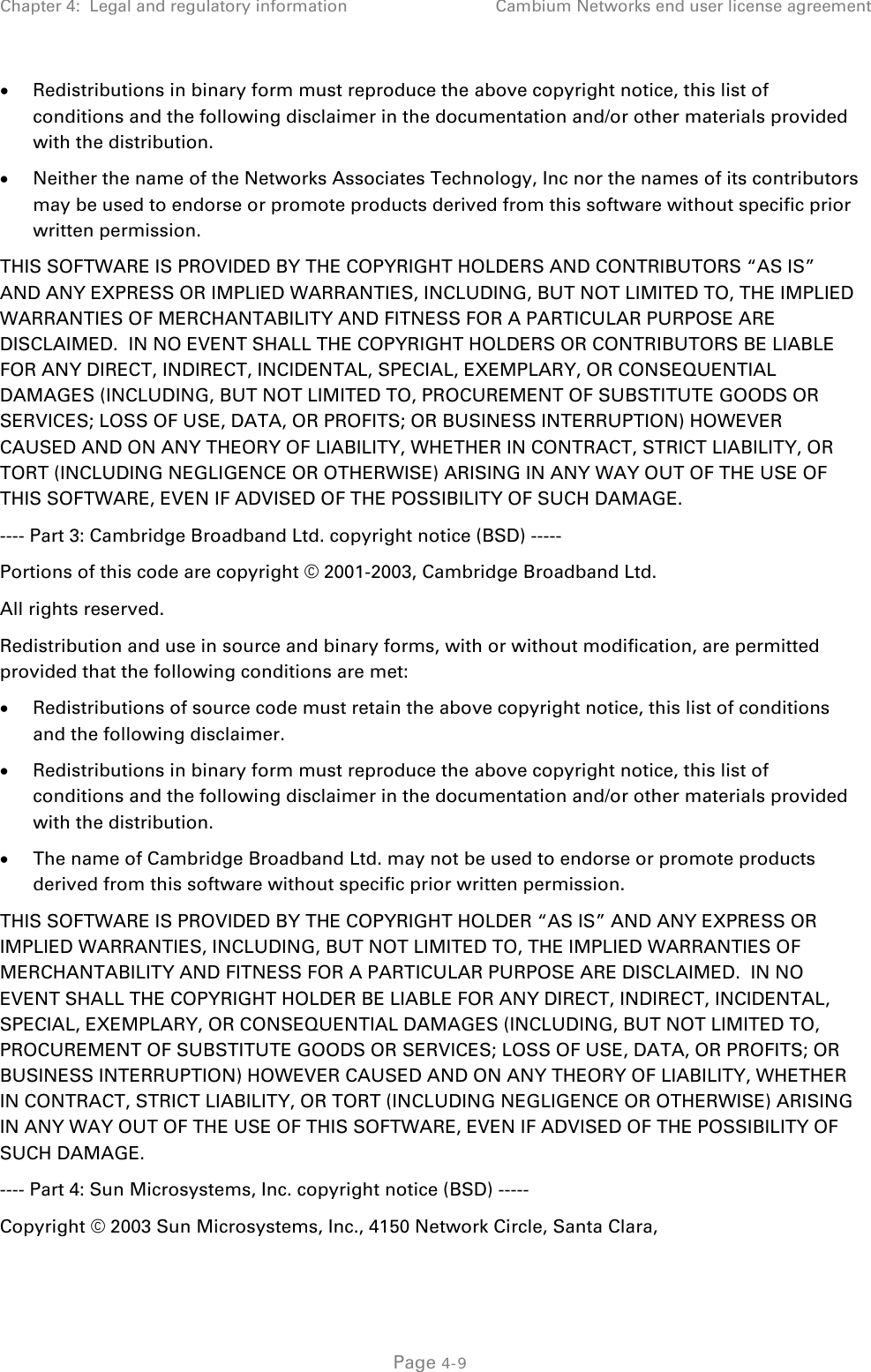
![Chapter 3: System planning Security planning Identify the security level for each of the security roles. Three security levels are available: (a) No authentication, no privacy; (b) Authentication, no privacy; (c) Authentication, privacy. If authentication is required, identify the protocol. Two authentication protocols are available: MD5 or SHA. If privacy will be used, identify the protocol. Two privacy protocols are available: DES or AES (an AES 128-bit or 256-bit capability upgrade must be purchased). If authentication or authentication and privacy protocols are required, identify passphrases for each protocol for each SNMP user. It is considered good practice to use different passphrases for authentication and privacy. Passphrases must have length between 8 and 32 characters, and may contain any of the characters listed in Table 34. Table 34 Permitted character set for SNMPv3 passphrases Character Code Character Code <space> 32 ; 59 ! 33 < 60 “ 34 = 61 # 35 > 62 $ 36 ? 63 % 37 @ 64 & 38 A..Z 65..90 ' 39 [ 91 ( 40 \ 92 ) 41 ] 93 * 42 ^ 94 + 43 _ 95 , 44 ` 96 - 45 a..z 97..122 . 46 { 123 / 47 | 124 0..9 48..57 } 125 : 58 ~ 126 Identify up to two SNMP users that will be configured to receive notifications (traps). Identify the Internet address (IPv4 or IPv6) and UDP port number of the associated SNMP manager. Page 3-36](https://usermanual.wiki/Cambium-Networks/50650.User-Manual-Part-1/User-Guide-2061301-Page-121.png)


![Chapter 4: Legal and regulatory information Cambium Networks end user license agreement The word ‘cryptographic’ can be left out if the routines from the library being used are not cryptographic related. 4. If you include any Windows specific code (or a derivative thereof) from the apps directory (application code) you must include an acknowledgement: “This product includes software written by Tim Hudson (tjh@cryptsoft.com)” THIS SOFTWARE IS PROVIDED BY ERIC YOUNG “AS IS” AND ANY EXPRESS OR IMPLIED WARRANTIES, INCLUDING, BUT NOT LIMITED TO, THE IMPLIED WARRANTIES OF MERCHANTABILITY AND FITNESS FOR A PARTICULAR PURPOSE ARE DISCLAIMED. IN NO EVENT SHALL THE AUTHOR OR CONTRIBUTORS BE LIABLE FOR ANY DIRECT, INDIRECT, INCIDENTAL, SPECIAL, EXEMPLARY, OR CONSEQUENTIAL DAMAGES (INCLUDING, BUT NOT LIMITED TO, PROCUREMENT OF SUBSTITUTE GOODS OR SERVICES; LOSS OF USE, DATA, OR PROFITS; OR BUSINESS INTERRUPTION) HOWEVER CAUSED AND ON ANY THEORY OF LIABILITY, WHETHER IN CONTRACT, STRICT LIABILITY, OR TORT (INCLUDING NEGLIGENCE OR OTHERWISE) ARISING IN ANY WAY OUT OF THE USE OF THIS SOFTWARE, EVEN IF ADVISED OF THE POSSIBILITY OF SUCH DAMAGE. The license and distribution terms for any publically available version or derivative of this code cannot be changed. i.e. this code cannot simply be copied and put under another distribution license [including the GNU Public License.] Zlib Copyright © 1995-2005 Jean-loup Gailly and Mark Adler This software is provided ‘as-is’, without any express or implied warranty. In no event will the authors be held liable for any damages arising from the use of this software. Permission is granted to anyone to use this software for any purpose, including commercial applications, and to alter it and redistribute it freely, subject to the following restrictions: 1. The origin of this software must not be misrepresented; you must not claim that you wrote the original software. If you use this software in a product, an acknowledgment in the product documentation would be appreciated but is not required. 2. Altered source versions must be plainly marked as such, and must not be misrepresented as being the original software. 3. This notice may not be removed or altered from any source distribution. Jean-loup Gailly jloup@gzip.org Mark Adler madler@alumni.caltech.edu Page 4-14](https://usermanual.wiki/Cambium-Networks/50650.User-Manual-Part-1/User-Guide-2061301-Page-175.png)
![Chapter 4: Legal and regulatory information Cambium Networks end user license agreement and charge a fee for, acceptance of support, warranty, indemnity, or other liability obligations and/or rights consistent with this License. However, in accepting such obligations, You may act only on Your own behalf and on Your sole responsibility, not on behalf of any other Contributor, and only if You agree to indemnify, defend, and hold each Contributor harmless for any liability incurred by, or claims asserted against, such Contributor by reason of your accepting any such warranty or additional liability. END OF TERMS AND CONDITIONS APPENDIX: How to apply the Apache License to your work. To apply the Apache License to your work, attach the following boilerplate notice, with the fields enclosed by brackets "[]" replaced with your own identifying information. (Don't include the brackets!) The text should be enclosed in the appropriate comment syntax for the file format. We also recommend that a file or class name and description of purpose be included on the same "printed page" as the copyright notice for easier identification within third-party archives. Copyright [yyyy] [name of copyright owner] Licensed under the Apache License, Version 2.0 (the "License"); you may not use this file except in compliance with the License. You may obtain a copy of the License at http://www.apache.org/licenses/LICENSE-2.0 Unless required by applicable law or agreed to in writing, software distributed under the License is distributed on an "AS IS" BASIS, WITHOUT WARRANTIES OR CONDITIONS OF ANY KIND, either express or implied. See the License for the specific language governing permissions and limitations under the License. Page 4-21](https://usermanual.wiki/Cambium-Networks/50650.User-Manual-Part-1/User-Guide-2061301-Page-182.png)