Cambium Networks 50650 Wireless Ethernet Bridge User Manual PTP 650 Series User Guide
Cambium Networks Limited Wireless Ethernet Bridge PTP 650 Series User Guide
UserManual.wiki
>
Cambium Networks
>
50650 User Manual
>
User Guide Part 1
Contents
1.
User Manual Part 1
2.
User Manual Part 2
3.
Installation Guide
4.
User Guide Part 1
5.
User Guide Part 2
6.
User Guide Part 3
User Guide Part 1
Navigation menu
Upload a User Manual
Namespaces
Wiki Guide
HTML
PDF
Info
Views
User Manual
Discussion / Help
Navigation


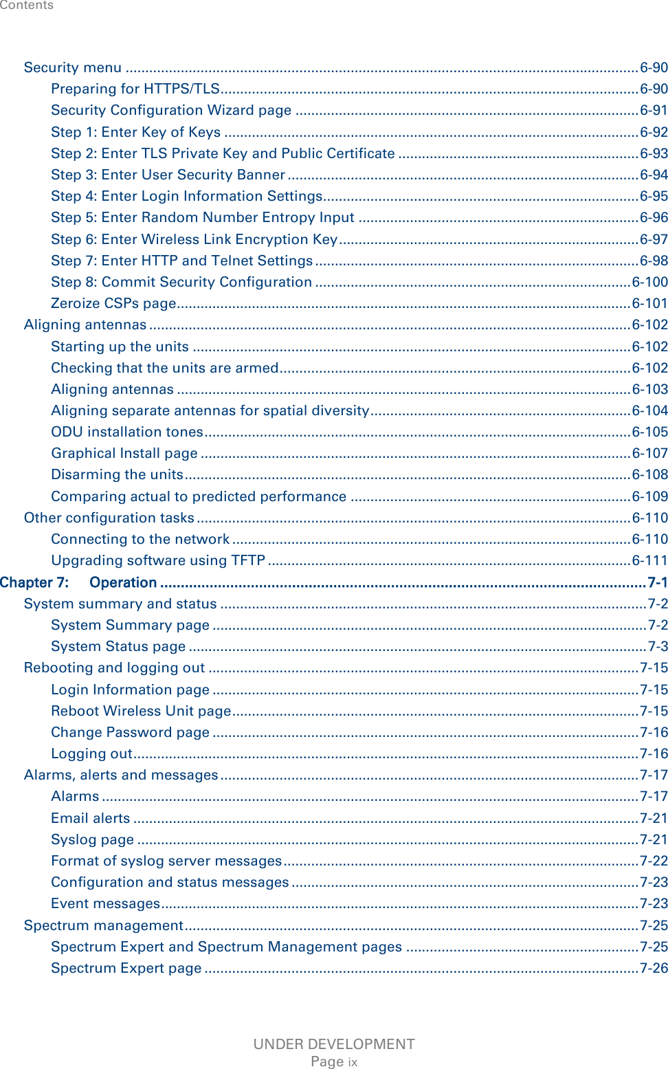

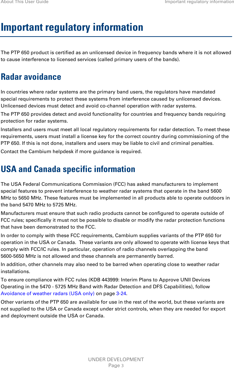
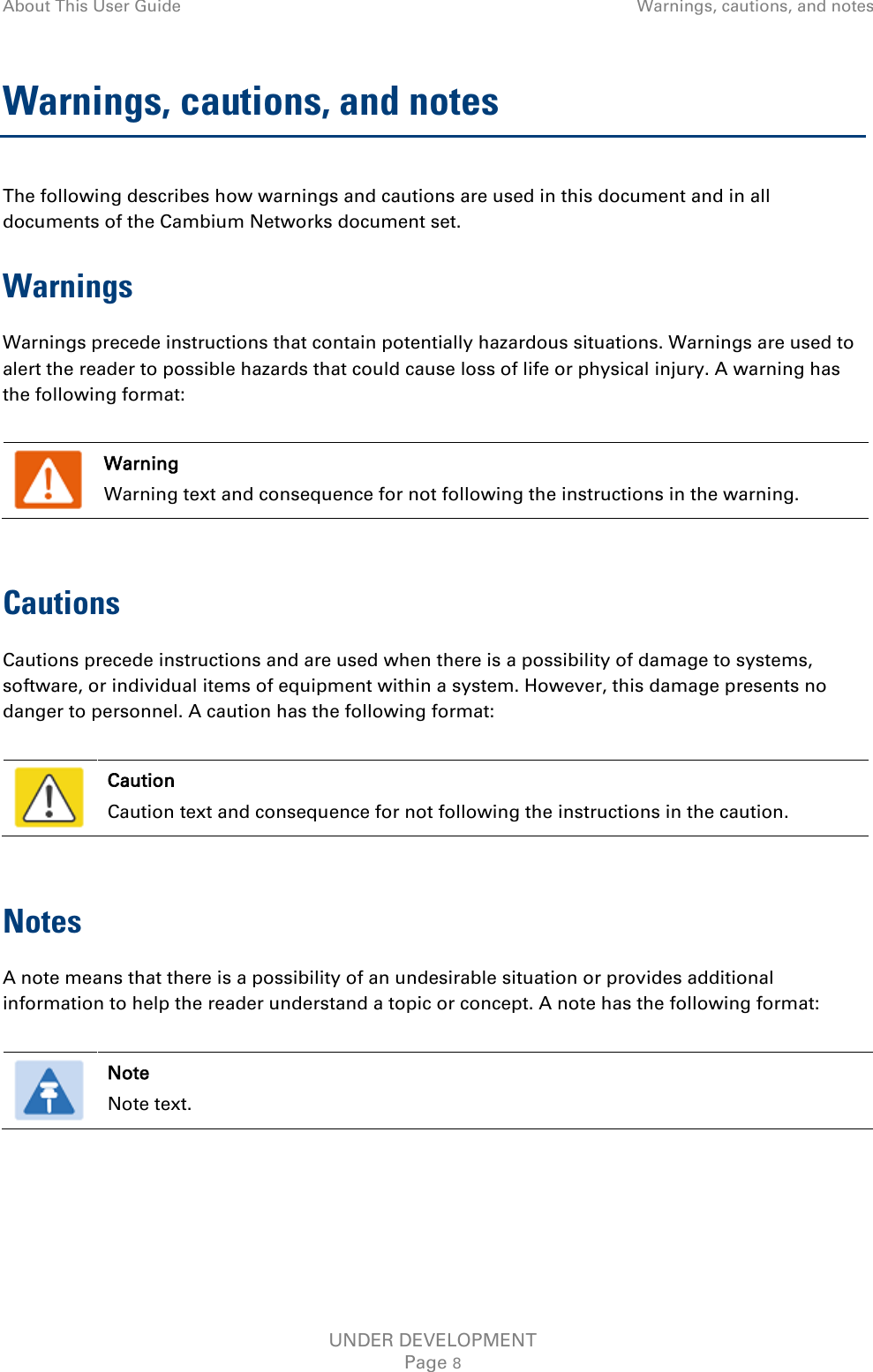
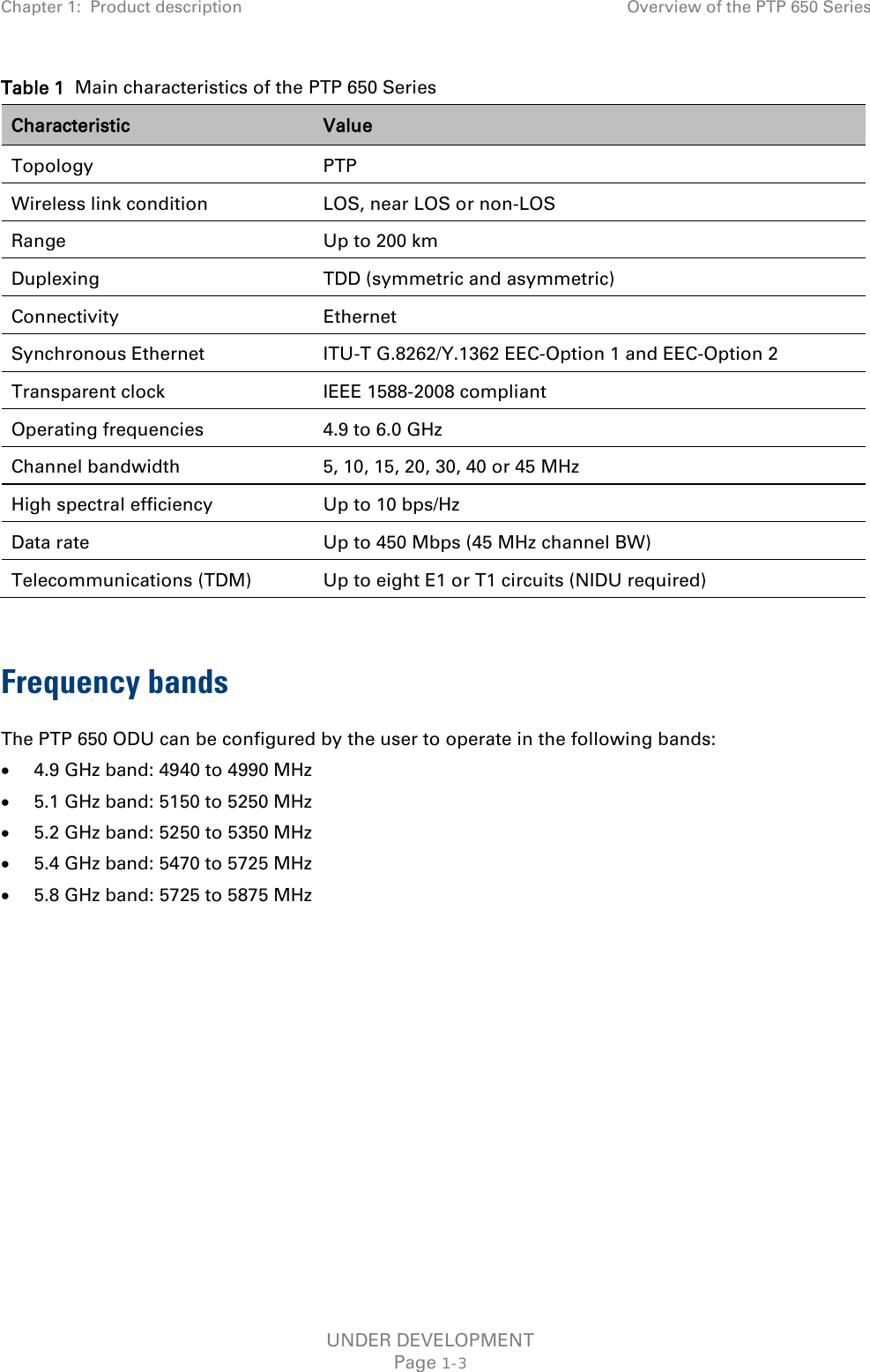
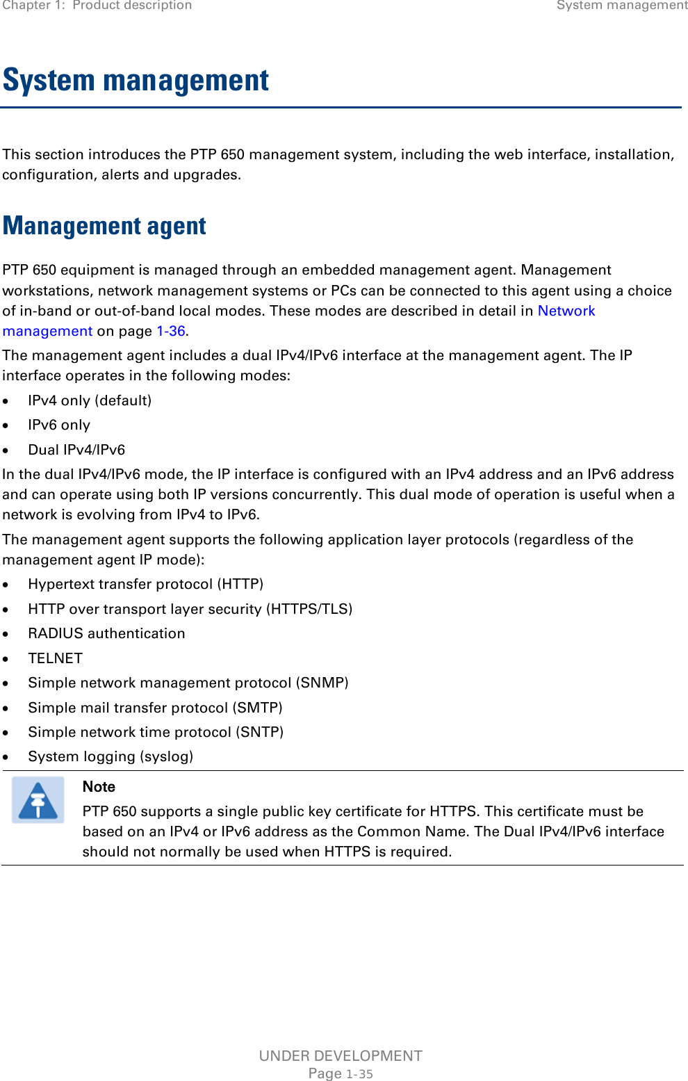
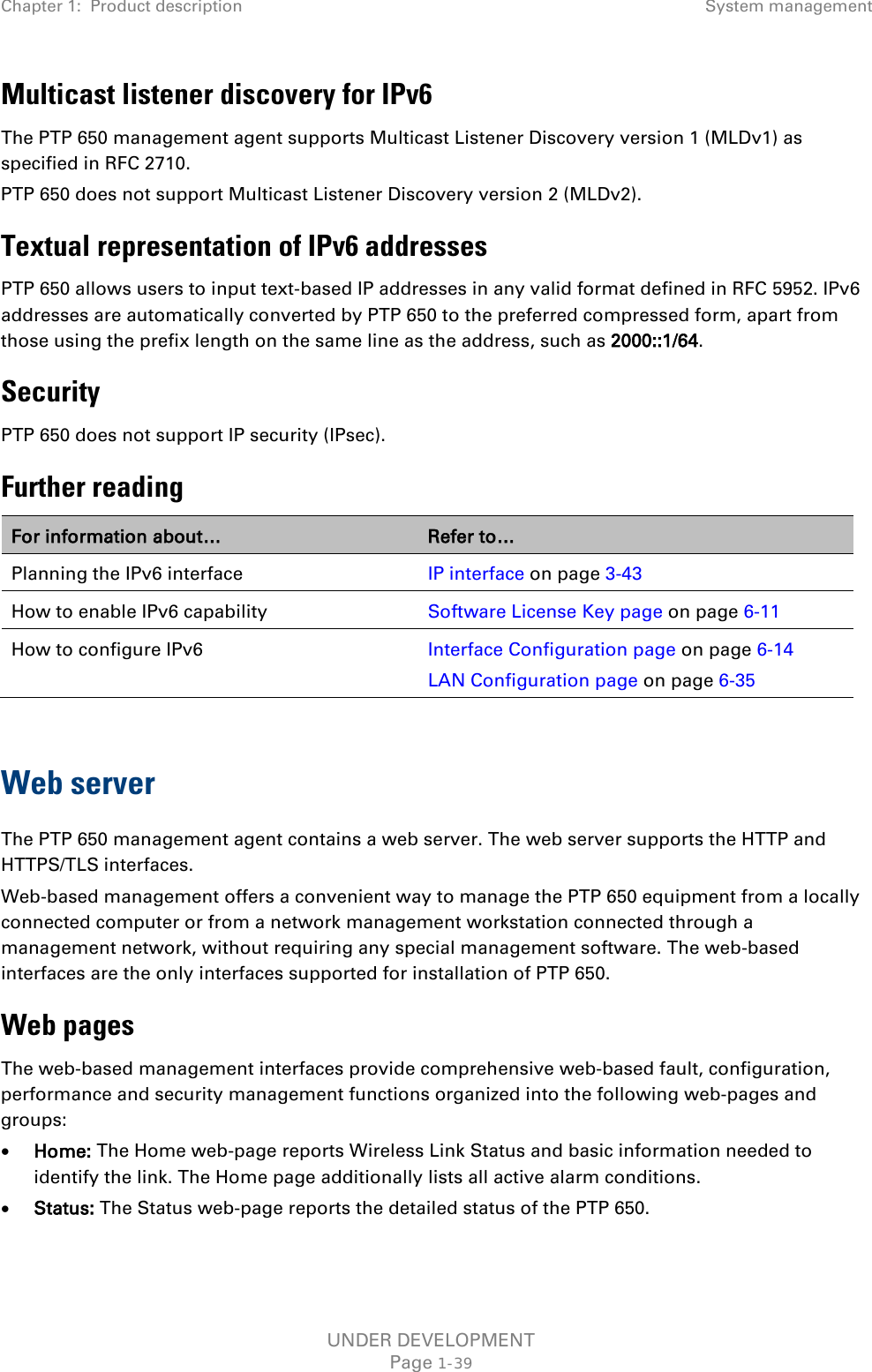
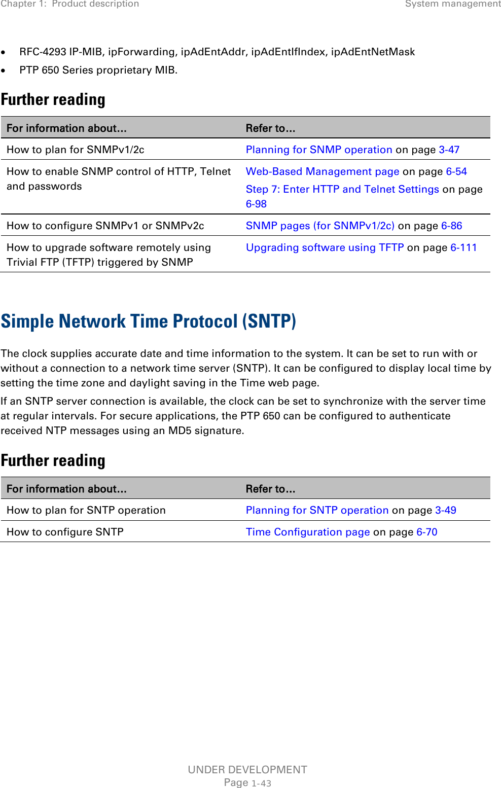


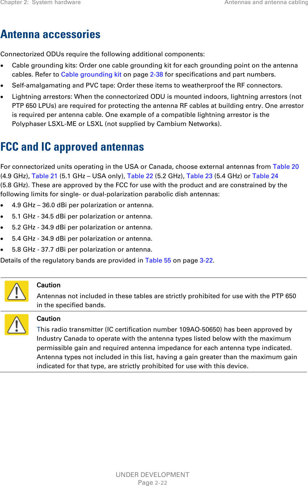

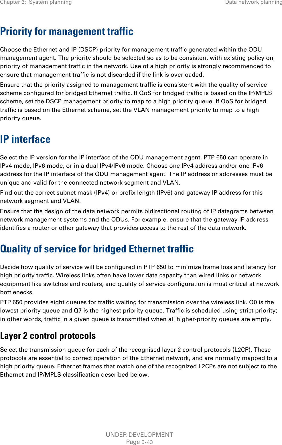

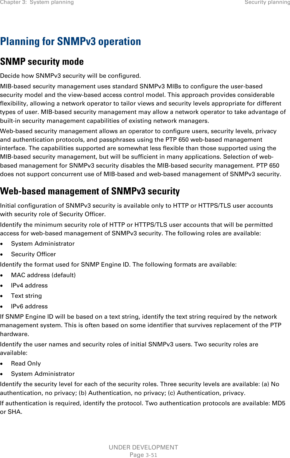
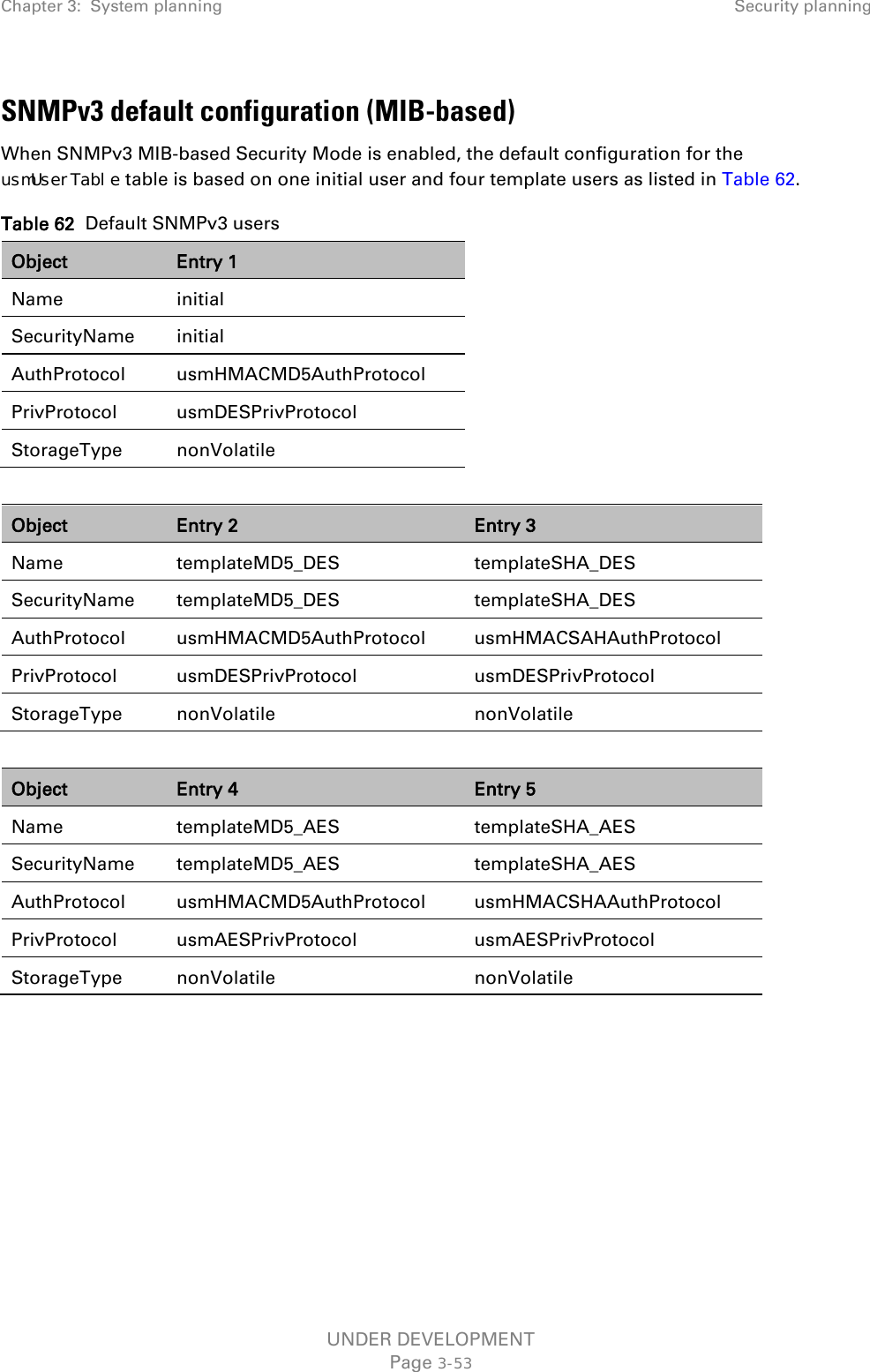
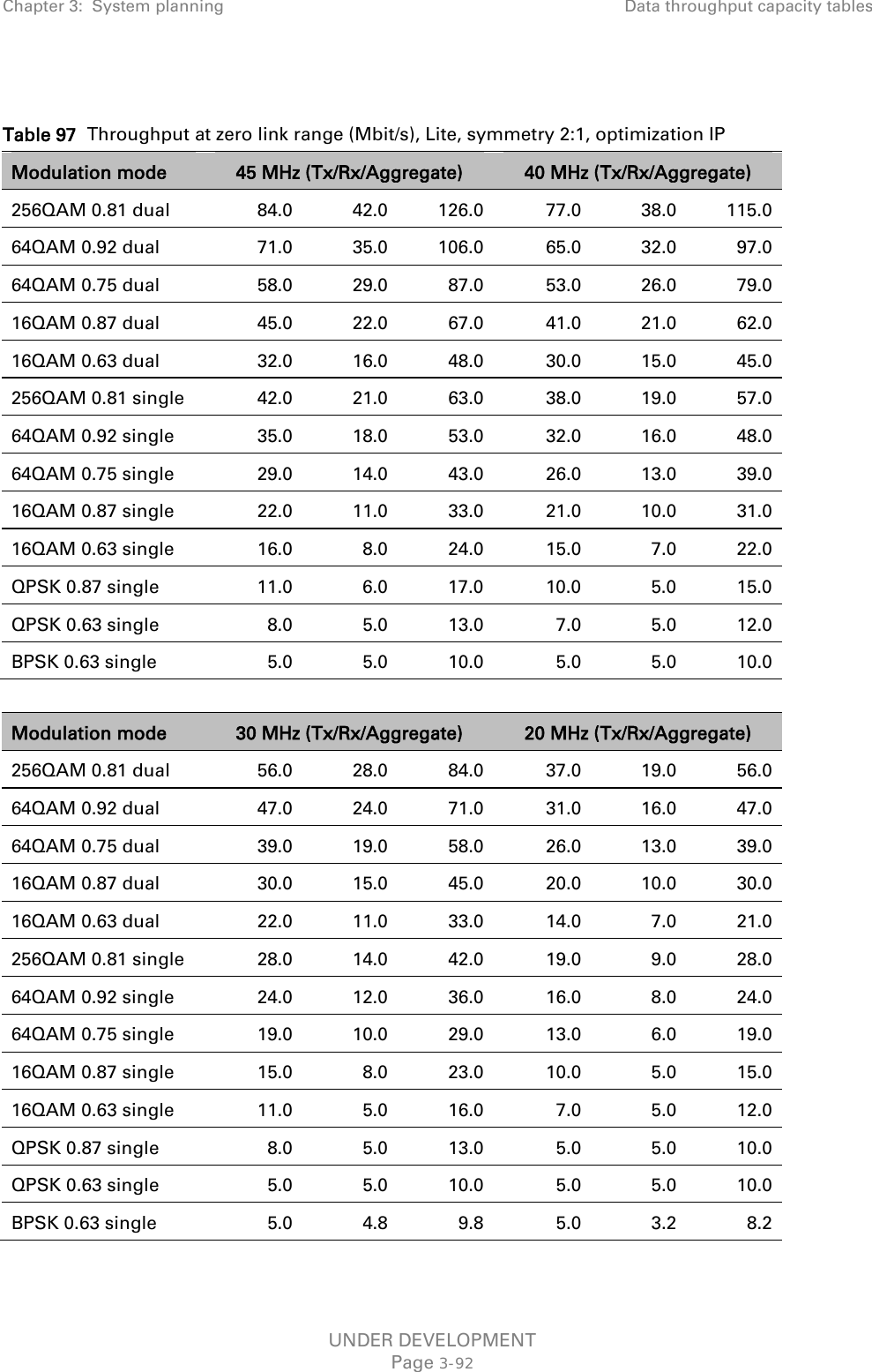
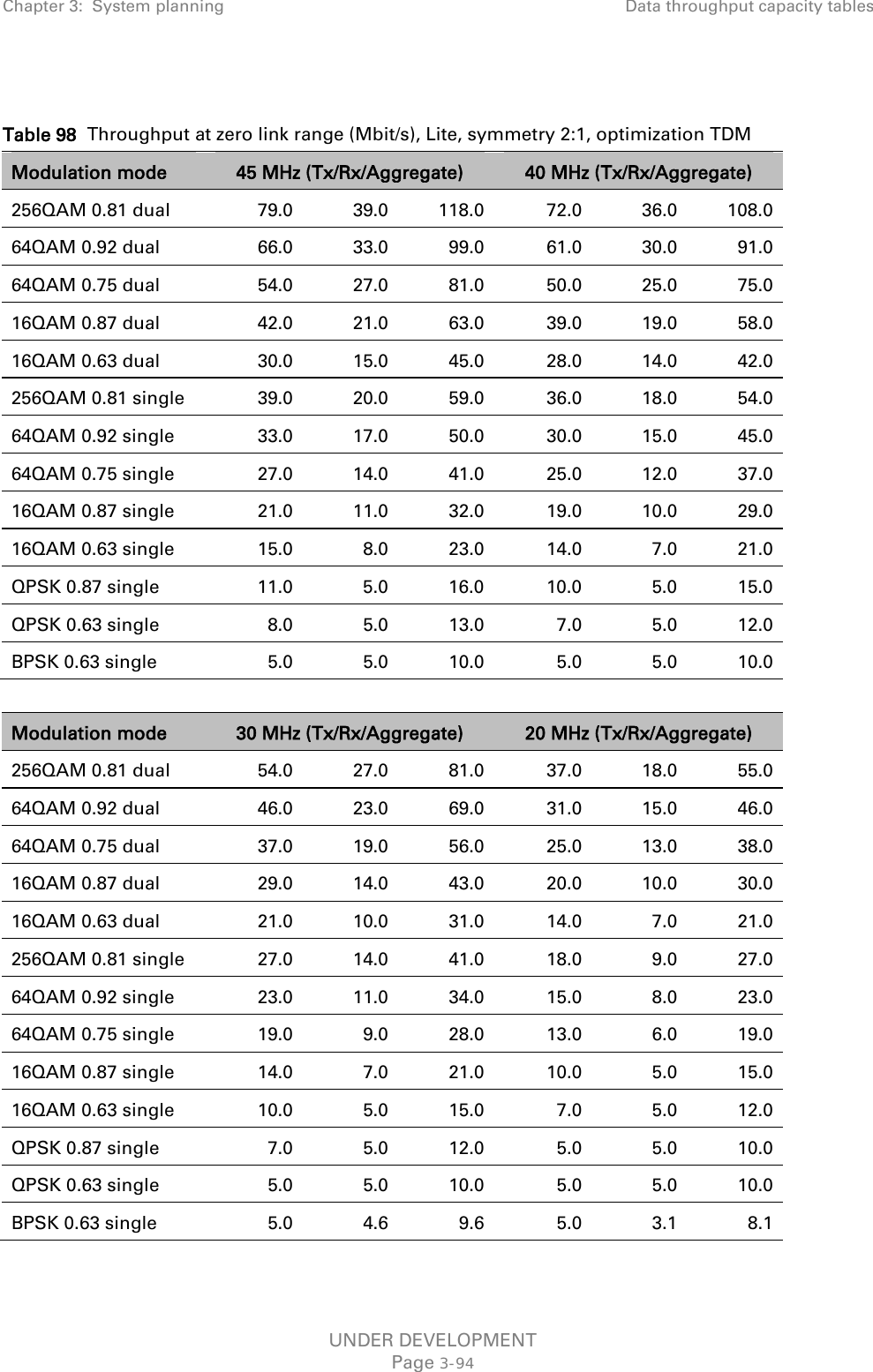
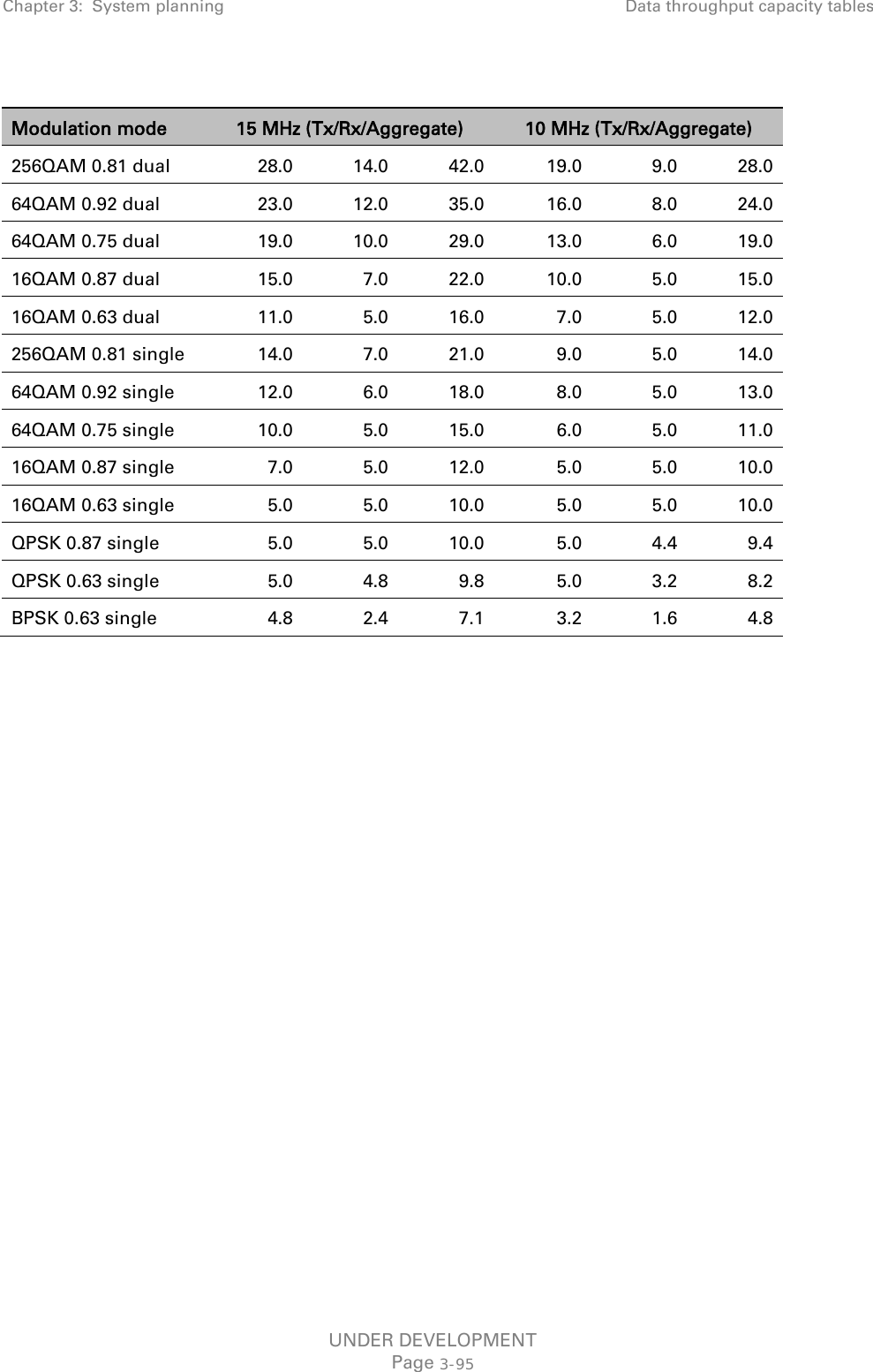
![Chapter 3: System planning Security planning If privacy will be used, identify the protocol. Two privacy protocols are available: DES or AES (an AES 128-bit or 256-bit capability upgrade must be purchased). If authentication or authentication and privacy protocols are required, identify passphrases for each protocol for each SNMP user. It is considered good practice to use different passphrases for authentication and privacy. Passphrases must have length between 8 and 32 characters, and may contain any of the characters listed in Table 61. Table 61 Permitted character set for SNMPv3 passphrases Character Code Character Code <space> 32 ; 59 ! 33 < 60 “ 34 = 61 # 35 > 62 $ 36 ? 63 % 37 @ 64 & 38 A..Z 65..90 ' 39 [ 91 ( 40 \ 92 ) 41 ] 93 * 42 ^ 94 + 43 _ 95 , 44 ` 96 - 45 a..z 97..122 . 46 { 123 / 47 | 124 0..9 48..57 } 125 : 58 ~ 126 Identify up to two SNMP users that will be configured to receive notifications (traps). Identify the Internet address (IPv4 or IPv6) and UDP port number of the associated SNMP manager. UNDER DEVELOPMENT Page 3-52](https://usermanual.wiki/Cambium-Networks/50650.User-Guide-Part-1/User-Guide-2331812-Page-182.png)