Cambium Networks 50650 Wireless Ethernet Bridge User Manual Installation Guide
Cambium Networks Limited Wireless Ethernet Bridge Installation Guide
UserManual.wiki
>
Cambium Networks
>
50650 User Manual
>
Installation Guide
Contents
1.
User Manual Part 1
2.
User Manual Part 2
3.
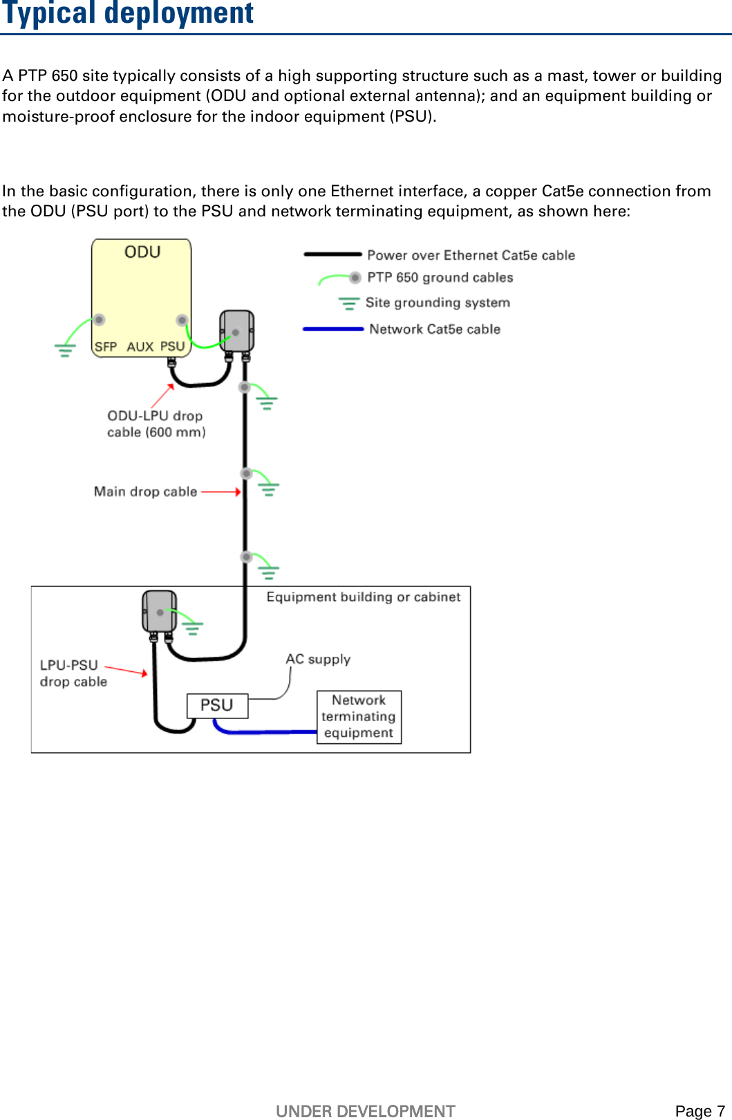
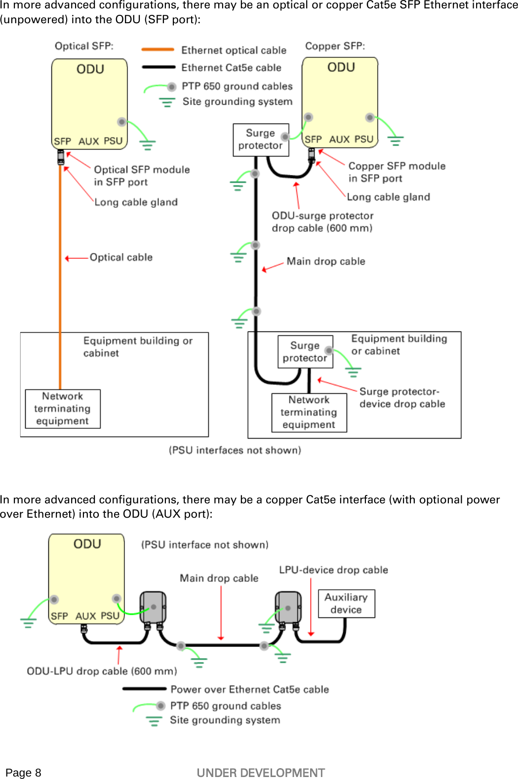
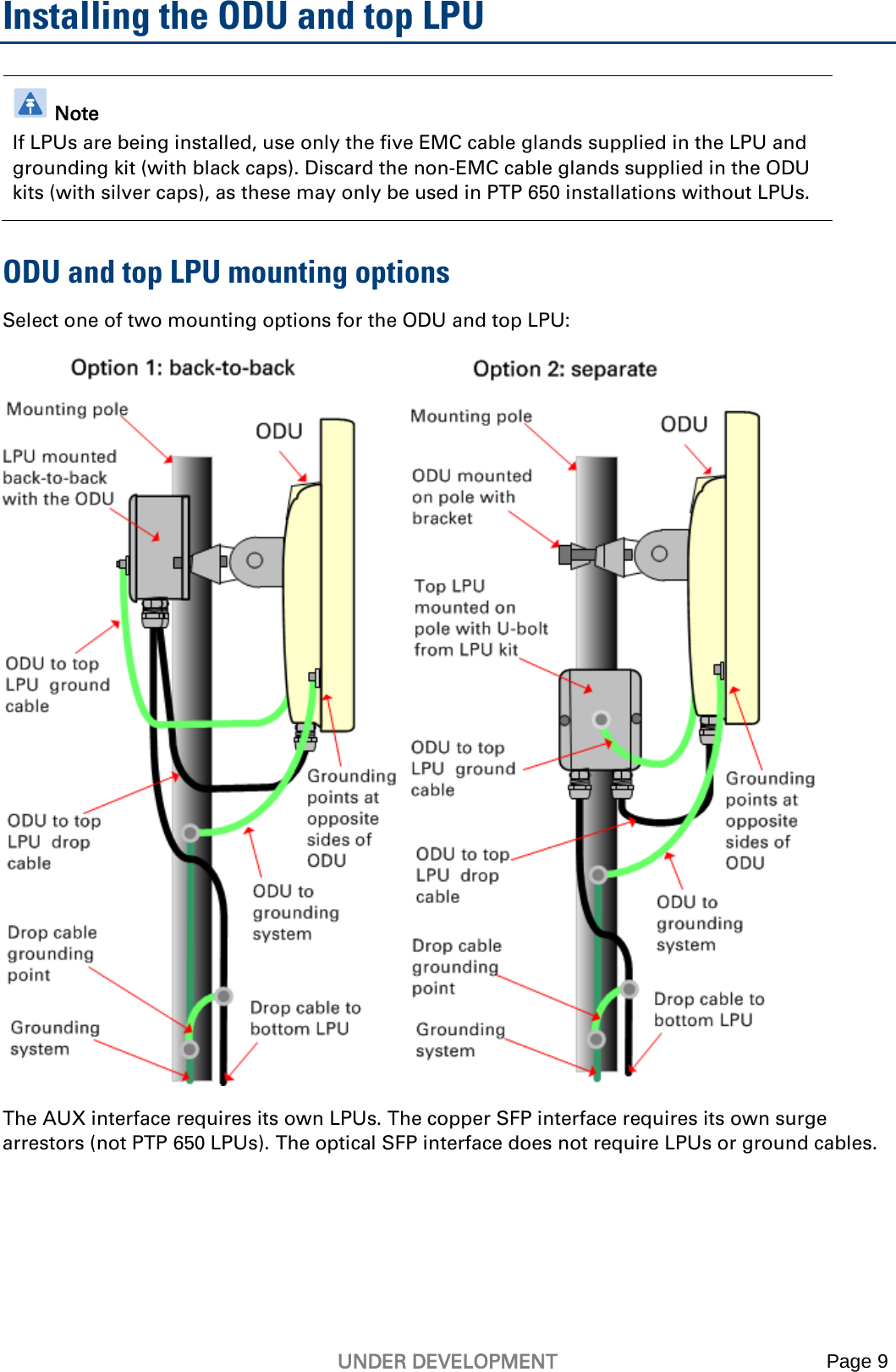
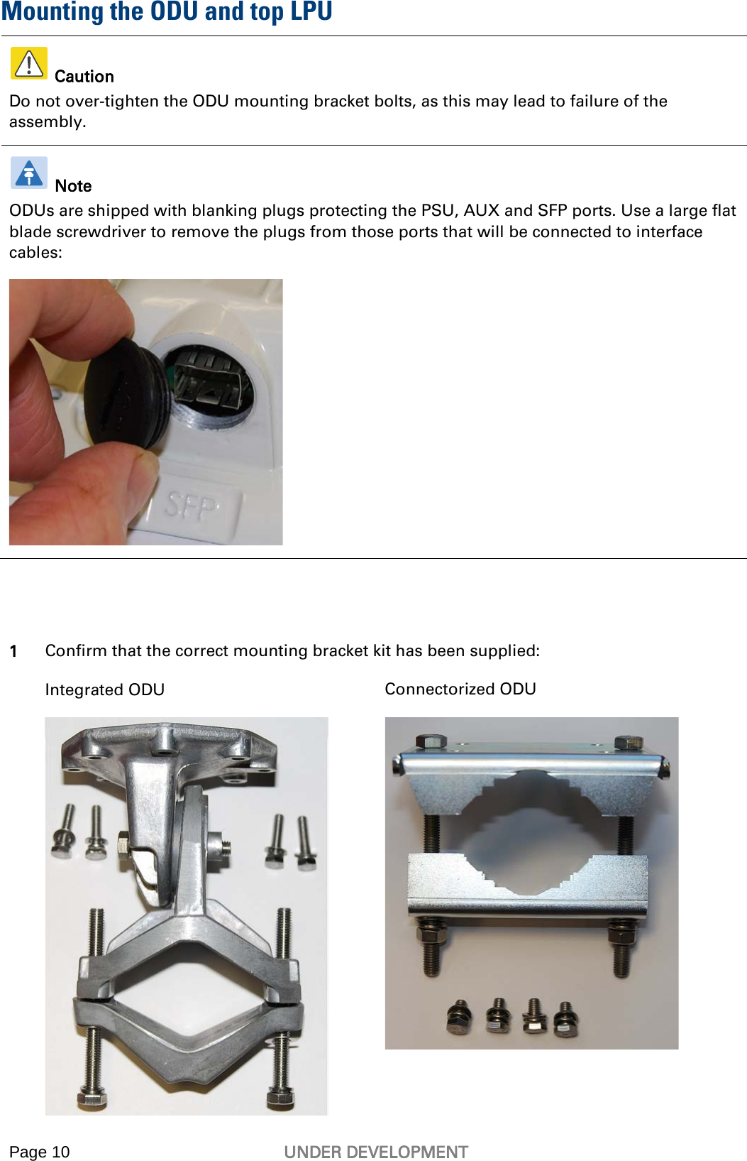
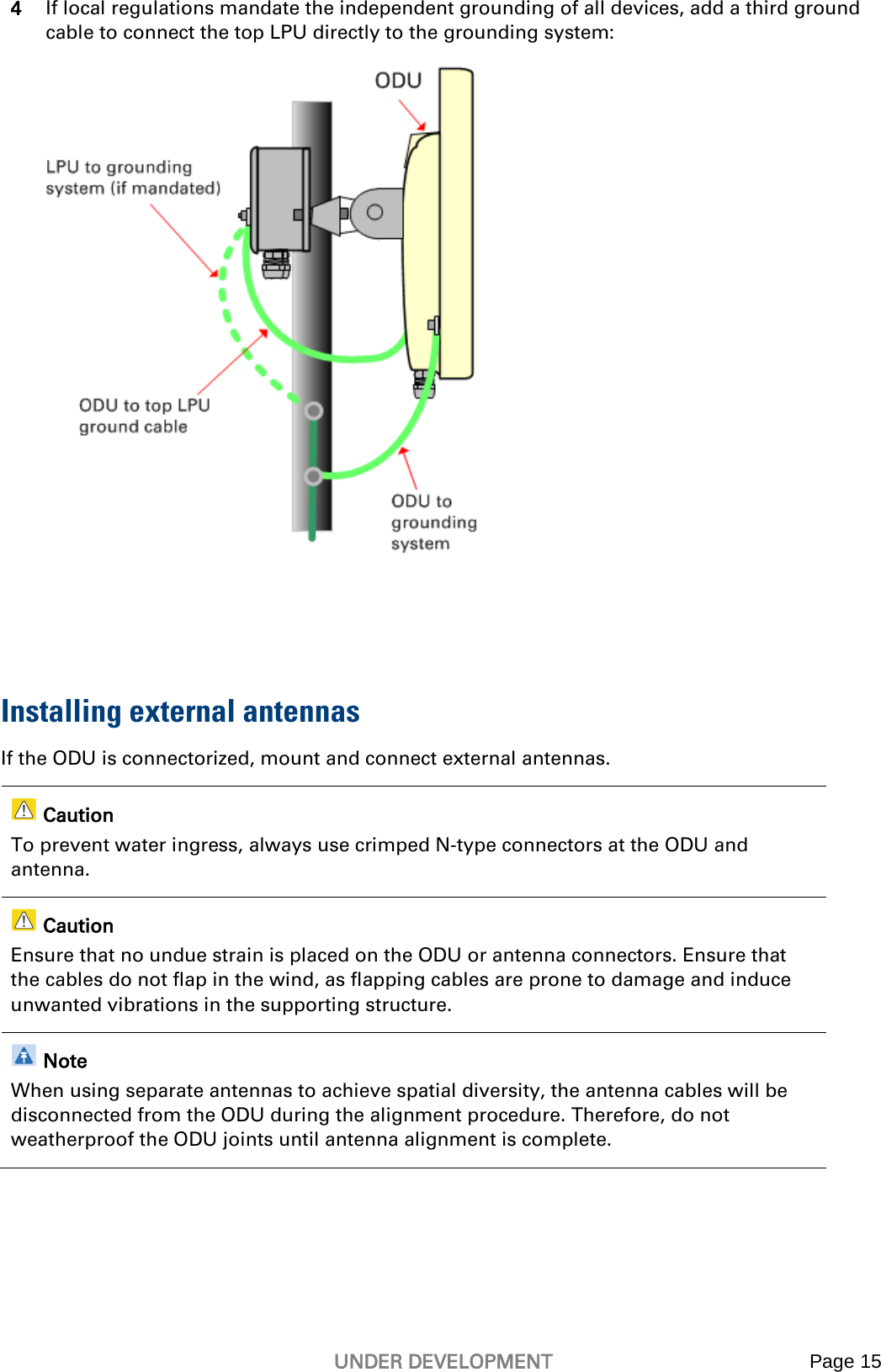
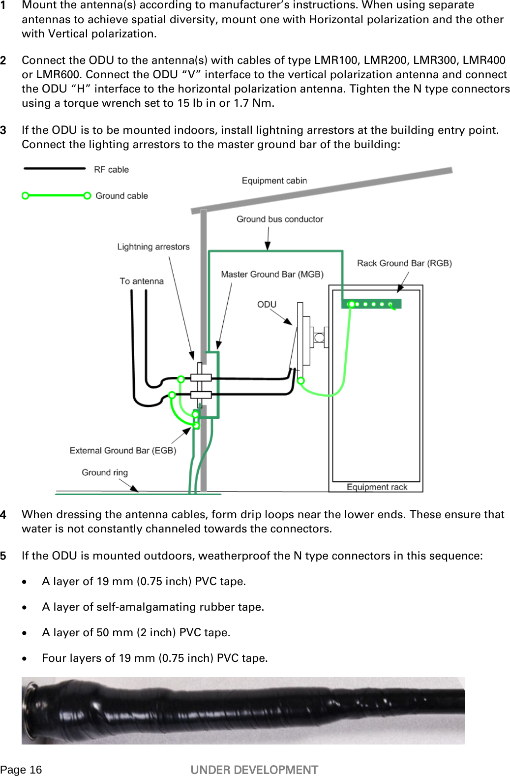
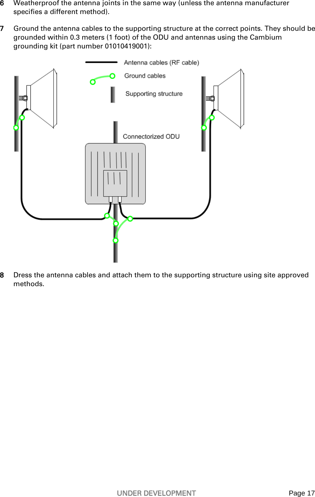
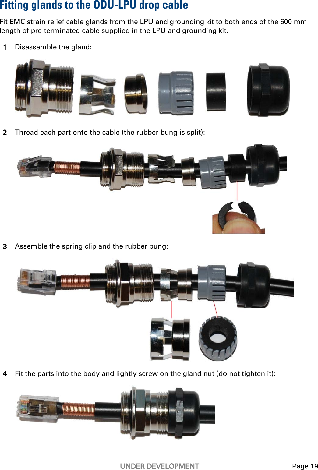
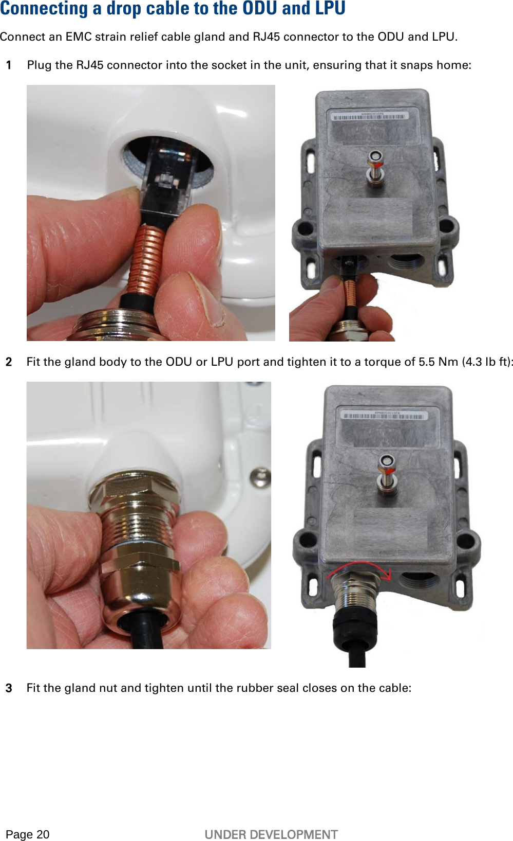
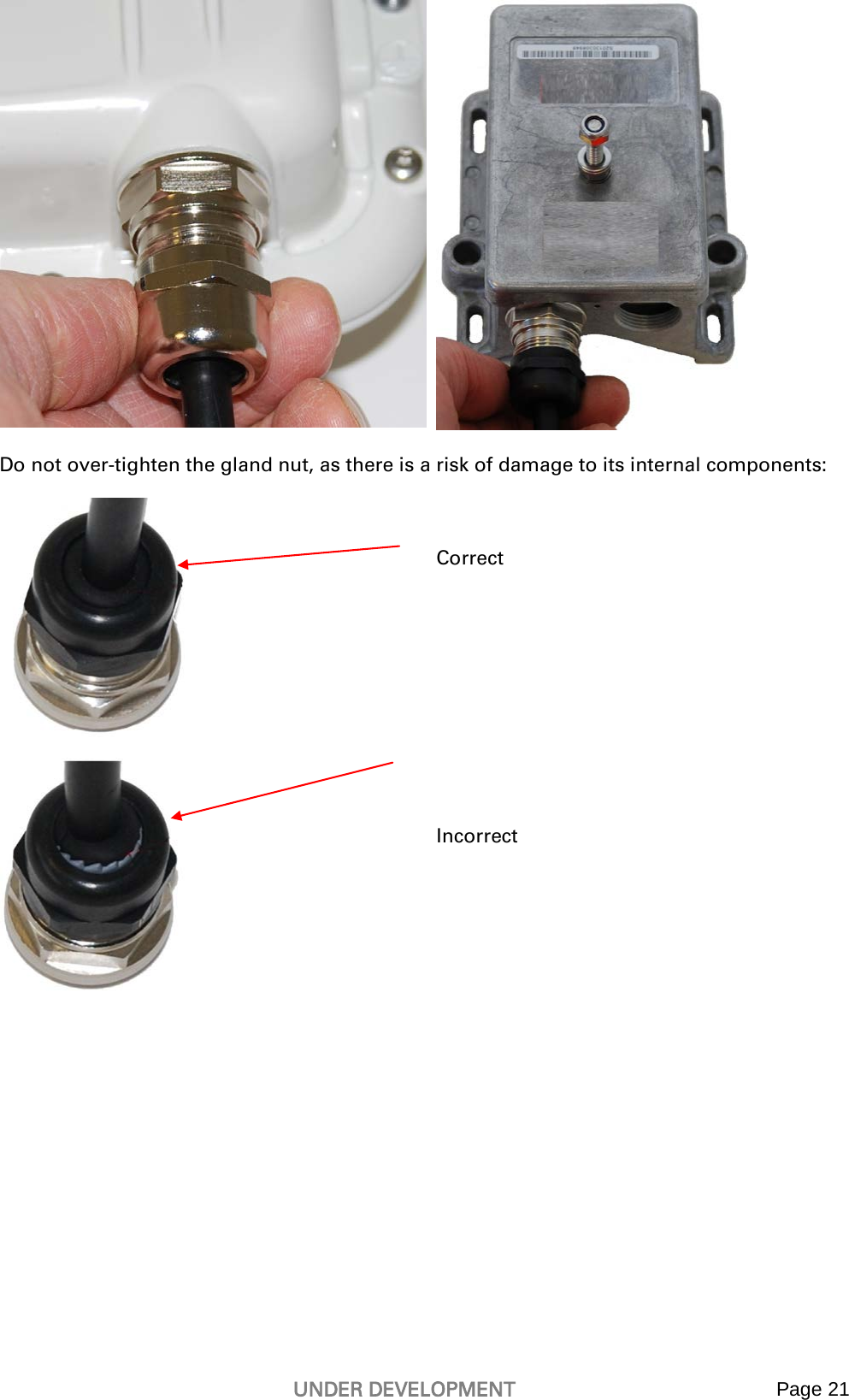
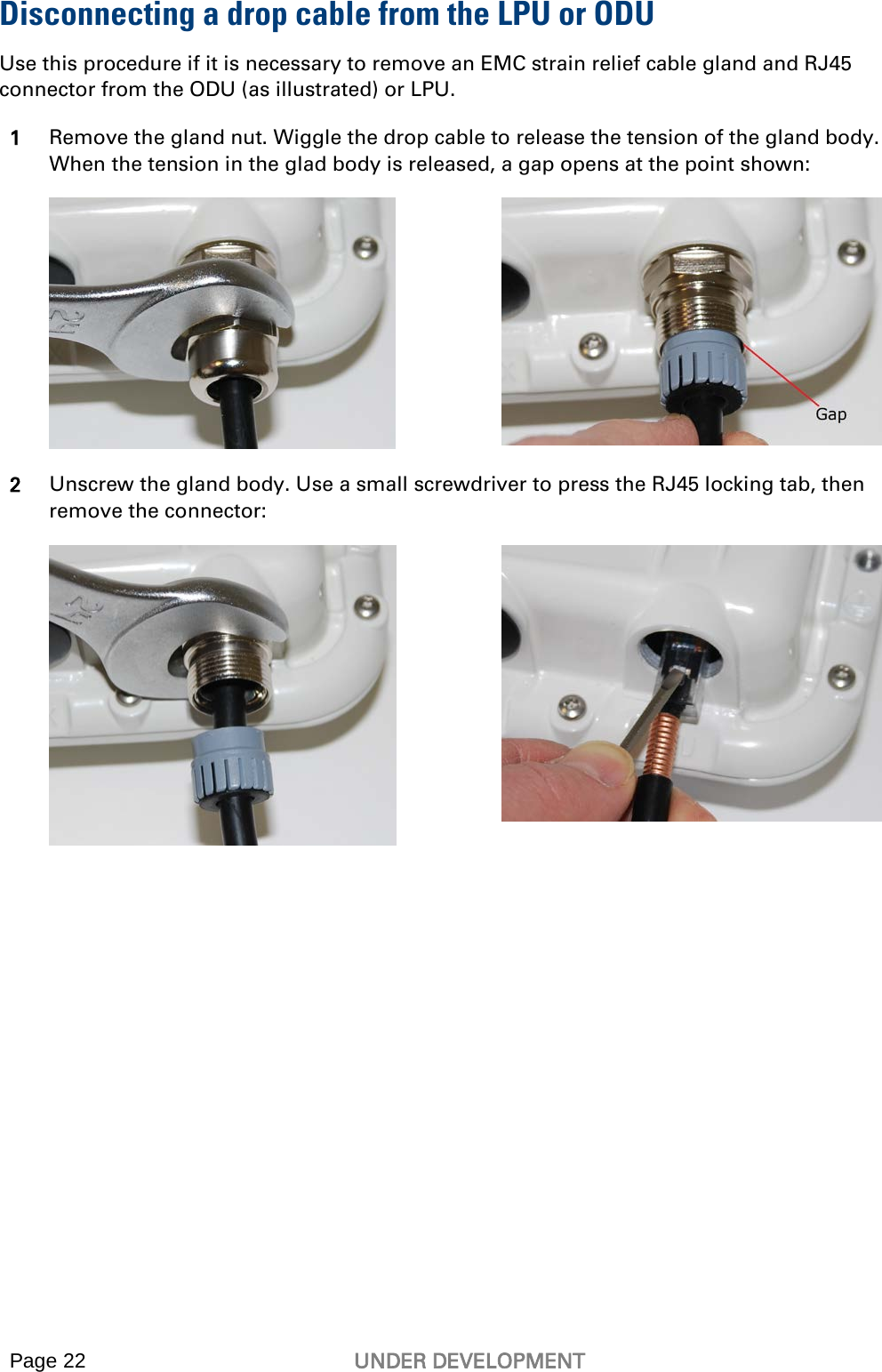
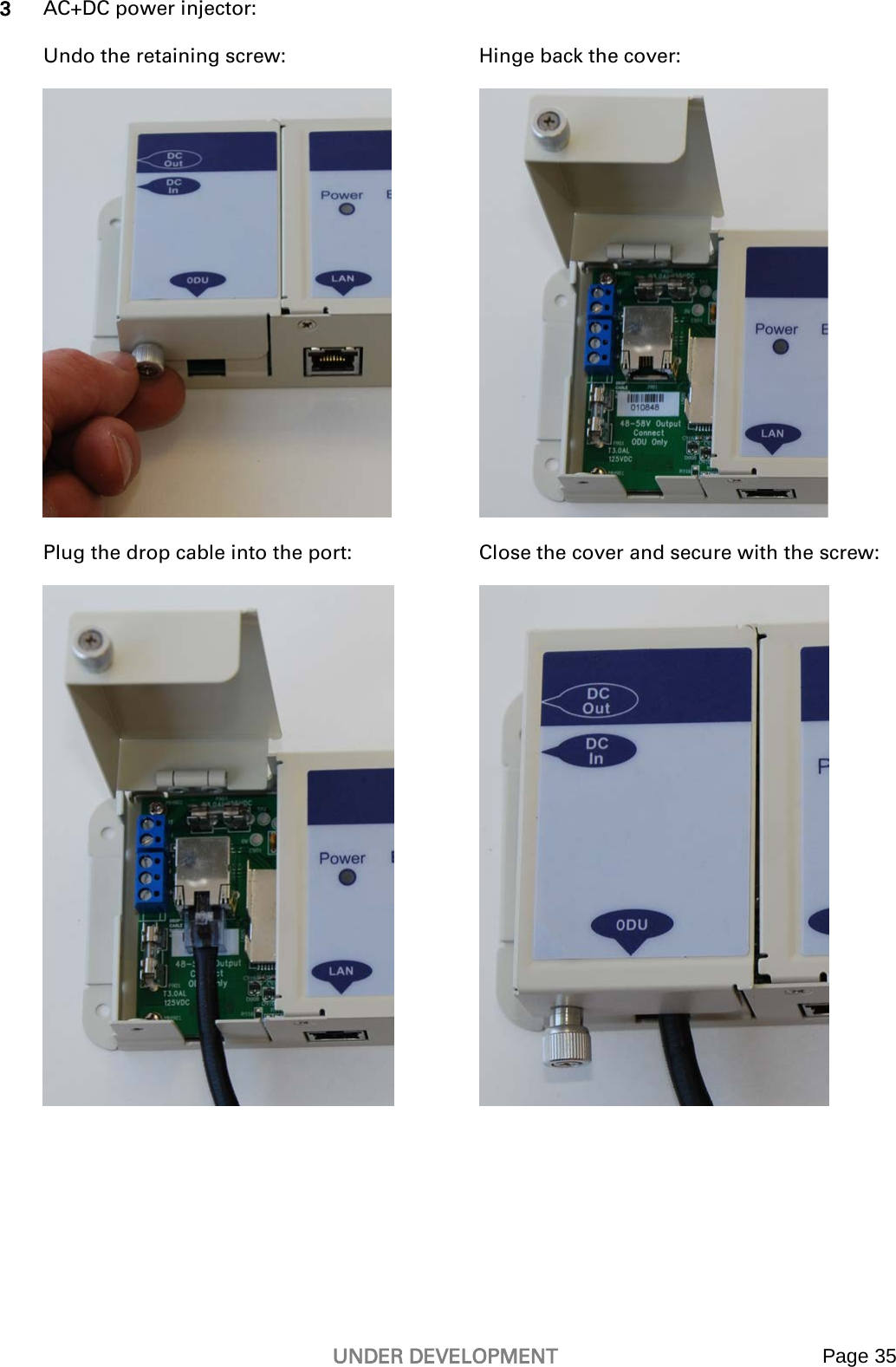
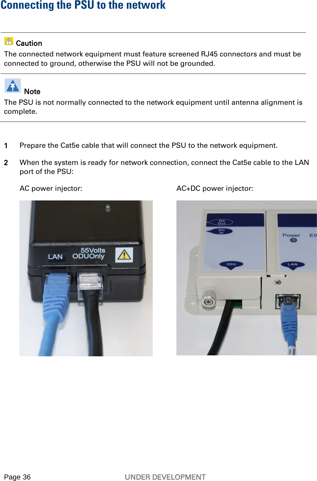
Installation Guide
4.
User Guide Part 1
5.
User Guide Part 2
6.
User Guide Part 3
Installation Guide
Navigation menu
Upload a User Manual
Namespaces
Wiki Guide
HTML
PDF
Info
Views
User Manual
Discussion / Help
Navigation