Cambium Networks 50650 Wireless Ethernet Bridge User Manual PTP 650 Series User Guide
Cambium Networks Limited Wireless Ethernet Bridge PTP 650 Series User Guide
Contents
User Guide Part 2

Chapter 4: Legal and regulatory information
This chapter provides end user license agreements and regulatory notifications.
Caution
Intentional or unintentional changes or modifications to the equipment must not be
made unless under the express consent of the party responsible for compliance. Any
such modifications could void the user’s authority to operate the equipment and will
void the manufacturer’s warranty.
Attention
Changements ou modifications Intentionnels ou non de l'équipement ne doivent pas
être entrepris sans l'autorisation de l’organisme responsable de la déclaration de
conformité. Ces modifications ou changements pourraient invalider le droit de
l'utilisateur à utiliser cet appareil et annuleraient la garantie du fabricant.
The following topics are described in this chapter:
• Cambium Networks end user license agreement on page 4-2 contains the Cambium and third
party license agreements for the PTP 650 Series products.
• Compliance with safety standards on page 4-22 lists the safety specifications against which the
PTP 650 has been tested and certified. It also describes how to keep RF exposure within safe
limits.
• Compliance with radio regulations on page 4-27 describes how the PTP 650 complies with the
radio regulations that are in force in various countries, and contains notifications made to
regulatory bodies for the PTP 650.
UNDER DEVELOPMENT
Page 4-1

Chapter 4: Legal and regulatory information Cambium Networks end user license agreement
Cambium Networks end user license agreement
Acceptance of this agreement
In connection with Cambium Networks’ delivery of certain proprietary software or products
containing embedded or pre-loaded proprietary software, or both, Cambium Networks is willing to
license this certain proprietary software and the accompanying documentation to you only on the
condition that you accept all the terms in this End User License Agreement (“Agreement”).
IF YOU DO NOT AGREE TO THE TERMS OF THIS AGREEMENT, DO NOT USE THE PRODUCT OR
INSTALL THE SOFTWARE. INSTEAD, YOU MAY, FOR A FULL REFUND, RETURN THIS PRODUCT
TO THE LOCATION WHERE YOU ACQUIRED IT OR PROVIDE WRITTEN VERIFICATION OF
DELETION OF ALL COPIES OF THE SOFTWARE. ANY USE OF THE SOFTWARE, INCLUDING BUT
NOT LIMITED TO USE ON THE PRODUCT, WILL CONSTITUTE YOUR ACCEPTANCE TO THE
TERMS OF THIS AGREEMENT.
Definitions
In this Agreement, the word “Software” refers to the set of instructions for computers, in
executable form and in any media, (which may include diskette, CD-ROM, downloadable internet,
hardware, or firmware) licensed to you. The word “Documentation” refers to electronic or printed
manuals and accompanying instructional aids licensed to you. The word “Product” refers to
Cambium Networks’ fixed wireless broadband devices for which the Software and Documentation
is licensed for use.
Grant of license
Cambium Networks Limited (“Cambium”) grants you (“Licensee” or “you”) a personal,
nonexclusive, non-transferable license to use the Software and Documentation subject to the
Conditions of Use set forth in “
Conditions of use
” and the terms and conditions of this Agreement.
Any terms or conditions relating to the Software and Documentation appearing on the face or
reverse side of any purchase order, purchase order acknowledgment or other order document that
are different from, or in addition to, the terms of this Agreement will not be binding on the parties,
even if payment is accepted.
UNDER DEVELOPMENT
Page 4-2
Chapter 4: Legal and regulatory information Cambium Networks end user license agreement
Conditions of use
Any use of the Software and Documentation outside of the conditions set forth in this Agreement
is strictly prohibited and will be deemed a breach of this Agreement.
1. Only you, your employees or agents may use the Software and Documentation. You will take all
necessary steps to insure that your employees and agents abide by the terms of this Agreement.
2. You will use the Software and Documentation (i) only for your internal business purposes; (ii)
only as described in the Software and Documentation; and (iii) in strict accordance with this
Agreement.
3. You may use the Software and Documentation, provided that the use is in conformance with the
terms set forth in this Agreement.
4. Portions of the Software and Documentation are protected by United States copyright laws,
international treaty provisions, and other applicable laws. Therefore, you must treat the Software
like any other copyrighted material (for example, a book or musical recording) except that you may
either: (i) make 1 copy of the transportable part of the Software (which typically is supplied on
diskette, CD-ROM, or downloadable internet), solely for back-up purposes; or (ii) copy the
transportable part of the Software to a PC hard disk, provided you keep the original solely for back-
up purposes. If the Documentation is in printed form, it may not be copied. If the Documentation
is in electronic form, you may print out 1 copy, which then may not be copied. With regard to the
copy made for backup or archival purposes, you agree to reproduce any Cambium Networks
copyright notice, and other proprietary legends appearing thereon. Such copyright notice(s) may
appear in any of several forms, including machine-readable form, and you agree to reproduce
such notice in each form in which it appears, to the extent it is physically possible to do so.
Unauthorized duplication of the Software or Documentation constitutes copyright infringement,
and in the United States is punishable in federal court by fine and imprisonment.
5. You will not transfer, directly or indirectly, any product, technical data or software to any
country for which the United States Government requires an export license or other governmental
approval without first obtaining such license or approval.
UNDER DEVELOPMENT
Page 4-3
Chapter 4: Legal and regulatory information Cambium Networks end user license agreement
Title and restrictions
If you transfer possession of any copy of the Software and Documentation to another party outside
of the terms of this agreement, your license is automatically terminated. Title and copyrights to
the Software and Documentation and any copies made by you remain with Cambium Networks
and its licensors. You will not, and will not permit others to: (i) modify, translate, decompile,
bootleg, reverse engineer, disassemble, or extract the inner workings of the Software or
Documentation, (ii) copy the look-and-feel or functionality of the Software or Documentation;
(iii) remove any proprietary notices, marks, labels, or logos from the Software or Documentation;
(iv) rent or transfer all or some of the Software or Documentation to any other party without
Cambium’s prior written consent; or (v) utilize any computer software or hardware which is
designed to defeat any copy protection device, should the Software and Documentation be
equipped with such a protection device. If the Software and Documentation is provided on
multiple types of media (such as diskette, CD-ROM, downloadable internet), then you will only use
the medium which best meets your specific needs, and will not loan, rent, lease, or transfer the
other media contained in the package without Cambium’s written consent. Unauthorized copying
of the Software or Documentation, or failure to comply with any of the provisions of this
Agreement, will result in automatic termination of this license.
Confidentiality
You acknowledge that all Software and Documentation contain valuable proprietary information
and trade secrets and that unauthorized or improper use of the Software and Documentation will
result in irreparable harm to Cambium Networks for which monetary damages would be
inadequate and for which Cambium Networks will be entitled to immediate injunctive relief. If
applicable, you will limit access to the Software and Documentation to those of your employees
and agents who need to use the Software and Documentation for your internal business purposes,
and you will take appropriate action with those employees and agents to preserve the
confidentiality of the Software and Documentation, using the same degree of care to avoid
unauthorized or improper disclosure as you use for the protection of your own proprietary
software, but in no event less than reasonable care.
You have no obligation to preserve the confidentiality of any proprietary information that: (i) was
in the public domain at the time of disclosure; (ii) entered the public domain through no fault of
yours; (iii) was given to you free of any obligation to keep it confidential; (iv) is independently
developed by you; or (v) is disclosed as required by law provided that you notify Cambium
Networks prior to such disclosure and provide Cambium Networks with a reasonable opportunity
to respond.
UNDER DEVELOPMENT
Page 4-4
Chapter 4: Legal and regulatory information Cambium Networks end user license agreement
Right to use Cambium’s name
Except as required in “
Conditions of use
”, you will not, during the term of this Agreement or
thereafter, use any trademark of Cambium Networks, or any word or symbol likely to be confused
with any Cambium Networks trademark, either alone or in any combination with another word or
words.
Transfer
The Software and Documentation may not be transferred to another party without the express
written consent of Cambium Networks, regardless of whether or not such transfer is accomplished
by physical or electronic means. Cambium’s consent may be withheld at its discretion and may be
conditioned upon transferee paying all applicable license fees and agreeing to be bound by this
Agreement.
Updates
During the first 12 months after purchase of a Product, or during the term of any executed
Maintenance and Support Agreement for the Product, you are entitled to receive Updates. An
“Update” means any code in any form which is a bug fix, patch, error correction, or minor
enhancement, but excludes any major feature added to the Software. Updates are available for
download at the support website.
Major features may be available from time to time for an additional license fee. If Cambium
Networks makes available to you major features and no other end user license agreement is
provided, then the terms of this Agreement will apply.
Maintenance
Except as provided above, Cambium Networks is not responsible for maintenance or field service
of the Software under this Agreement.
UNDER DEVELOPMENT
Page 4-5
Chapter 4: Legal and regulatory information Cambium Networks end user license agreement
Disclaimer
CAMBIUM NETWORKS DISCLAIMS ALL WARRANTIES OF ANY KIND, WHETHER EXPRESS,
IMPLIED, STATUTORY, OR IN ANY COMMUNICATION WITH YOU. CAMBIUM NETWORKS
SPECIFICALLY DISCLAIMS ANY WARRANTY INCLUDING THE IMPLIED WARRANTIES OF
MERCHANTABILTY, NONINFRINGEMENT, OR FITNESS FOR A PARTICULAR PURPOSE. THE
SOFTWARE AND DOCUMENTATION ARE PROVIDED “AS IS.” CAMBIUM NETWORKS DOES NOT
WARRANT THAT THE SOFTWARE WILL MEET YOUR REQUIREMENTS, OR THAT THE OPERATION
OF THE SOFTWARE WILL BE UNINTERRUPTED OR ERROR FREE, OR THAT DEFECTS IN THE
SOFTWARE WILL BE CORRECTED. CAMBIUM NETWORKS MAKES NO WARRANTY WITH
RESPECT TO THE CORRECTNESS, ACCURACY, OR RELIABILITY OF THE SOFTWARE AND
DOCUMENTATION. Some jurisdictions do not allow the exclusion of implied warranties, so the
above exclusion may not apply to you.
Limitation of liability
IN NO EVENT SHALL CAMBIUM NETWORKS BE LIABLE TO YOU OR ANY OTHER PARTY FOR ANY
DIRECT, INDIRECT, GENERAL, SPECIAL, INCIDENTAL, CONSEQUENTIAL, EXEMPLARY OR OTHER
DAMAGE ARISING OUT OF THE USE OR INABILITY TO USE THE PRODUCT (INCLUDING,
WITHOUT LIMITATION, DAMAGES FOR LOSS OF BUSINESS PROFITS, BUSINESS
INTERRUPTION, LOSS OF BUSINESS INFORMATION OR ANY OTHER PECUNIARY LOSS, OR
FROM ANY BREACH OF WARRANTY, EVEN IF CAMBIUM NETWORKS HAS BEEN ADVISED OF
THE POSSIBILITY OF SUCH DAMAGES. (Some states do not allow the exclusion or limitation of
incidental or consequential damages, so the above exclusion or limitation may not apply to you.)
IN NO CASE SHALL CAMBIUM’S LIABILITY EXCEED THE AMOUNT YOU PAID FOR THE PRODUCT.
U.S. government
If you are acquiring the Product on behalf of any unit or agency of the U.S. Government, the
following applies. Use, duplication, or disclosure of the Software and Documentation is subject to
the restrictions set forth in subparagraphs (c) (1) and (2) of the Commercial Computer Software –
Restricted Rights clause at FAR 52.227-19 (JUNE 1987), if applicable, unless being provided to the
Department of Defense. If being provided to the Department of Defense, use, duplication, or
disclosure of the Products is subject to the restricted rights set forth in subparagraph (c) (1) (ii) of
the Rights in Technical Data and Computer Software clause at DFARS 252.227-7013 (OCT 1988), if
applicable. Software and Documentation may or may not include a Restricted Rights notice, or
other notice referring specifically to the terms and conditions of this Agreement. The terms and
conditions of this Agreement will each continue to apply, but only to the extent that such terms
and conditions are not inconsistent with the rights provided to you under the aforementioned
provisions of the FAR and DFARS, as applicable to the particular procuring agency and
procurement transaction.
UNDER DEVELOPMENT
Page 4-6
Chapter 4: Legal and regulatory information Cambium Networks end user license agreement
Term of license
Your right to use the Software will continue in perpetuity unless terminated as follows. Your right
to use the Software will terminate immediately without notice upon a breach of this Agreement by
you. Within 30 days after termination of this Agreement, you will certify to Cambium Networks in
writing that through your best efforts, and to the best of your knowledge, the original and all
copies, in whole or in part, in any form, of the Software and all related material and
Documentation, have been destroyed, except that, with prior written consent from Cambium
Networks, you may retain one copy for archival or backup purposes. You may not sublicense,
assign or transfer the license or the Product, except as expressly provided in this Agreement. Any
attempt to otherwise sublicense, assign or transfer any of the rights, duties or obligations
hereunder is null and void.
Governing law
This Agreement is governed by the laws of the United States of America to the extent that they
apply and otherwise by the laws of the State of Illinois.
Assignment
This agreement may not be assigned by you without Cambium’s prior written consent.
Survival of provisions
The parties agree that where the context of any provision indicates an intent that it survives the
term of this Agreement, then it will survive.
Entire agreement
This agreement contains the parties’ entire agreement regarding your use of the Software and
may be amended only in writing signed by both parties, except that Cambium Networks may
modify this Agreement as necessary to comply with applicable laws.
Third party software
The software may contain one or more items of Third-Party Software supplied by other third-party
suppliers. The terms of this Agreement govern your use of any Third-Party Software UNLESS A
SEPARATE THIRD-PARTY SOFTWARE LICENSE IS INCLUDED, IN WHICH CASE YOUR USE OF THE
THIRD-PARTY SOFTWARE WILL THEN BE GOVERNED BY THE SEPARATE THIRD-PARTY LICENSE.
UNDER DEVELOPMENT
Page 4-7
Chapter 4: Legal and regulatory information Cambium Networks end user license agreement
Trademarks
Java Technology and/or J2ME : Java and all other Java-based marks are trademarks or
registered trademarks of Sun Microsystems, Inc. in the U.S. and other countries.
UNIX : UNIX is a registered trademark of The Open Group in the United States and other
countries.
Net SNMP
Various copyrights apply to this package, listed in various separate parts below. Please make sure
that you read all the parts.
---- Part 1: CMU/UCD copyright notice: (BSD like) -----
Copyright 1989, 1991, 1992 by Carnegie Mellon University
Derivative Work - 1996, 1998-2000
Copyright 1996, 1998-2000 The Regents of the University of California
All Rights Reserved
Permission to use, copy, modify and distribute this software and its documentation for any
purpose and without fee is hereby granted, provided that the above copyright notice appears in all
copies and that both that copyright notice and this permission notice appear in supporting
documentation, and that the name of CMU and The Regents of the University of California not be
used in advertising or publicity pertaining to distribution of the software without specific written
permission.
CMU AND THE REGENTS OF THE UNIVERSITY OF CALIFORNIA DISCLAIM ALL WARRANTIES
WITH REGARD TO THIS SOFTWARE, INCLUDING ALL IMPLIED WARRANTIES OF
MERCHANTABILITY AND FITNESS. IN NO EVENT SHALL CMU OR THE REGENTS OF THE
UNIVERSITY OF CALIFORNIA BE LIABLE FOR ANY SPECIAL, INDIRECT OR CONSEQUENTIAL
DAMAGES OR ANY DAMAGES WHATSOEVER RESULTING FROM THE LOSS OF USE, DATA OR
PROFITS, WHETHER IN AN ACTION OF CONTRACT, NEGLIGENCE OR OTHER TORTIOUS ACTION,
ARISING OUT OF OR IN CONNECTION WITH THE USE OR PERFORMANCE OF THIS SOFTWARE.
---- Part 2: Networks Associates Technology, Inc copyright notice (BSD) -----
Copyright © 2001-2003, Networks Associates Technology, Inc
All rights reserved.
Redistribution and use in source and binary forms, with or without modification, are permitted
provided that the following conditions are met:
• Redistributions of source code must retain the above copyright notice, this list of conditions
and the following disclaimer.
• Redistributions in binary form must reproduce the above copyright notice, this list of
conditions and the following disclaimer in the documentation and/or other materials provided
with the distribution.
• Neither the name of the Networks Associates Technology, Inc nor the names of its contributors
may be used to endorse or promote products derived from this software without specific prior
written permission.
UNDER DEVELOPMENT
Page 4-8
Chapter 4: Legal and regulatory information Cambium Networks end user license agreement
THIS SOFTWARE IS PROVIDED BY THE COPYRIGHT HOLDERS AND CONTRIBUTORS “AS IS”
AND ANY EXPRESS OR IMPLIED WARRANTIES, INCLUDING, BUT NOT LIMITED TO, THE IMPLIED
WARRANTIES OF MERCHANTABILITY AND FITNESS FOR A PARTICULAR PURPOSE ARE
DISCLAIMED. IN NO EVENT SHALL THE COPYRIGHT HOLDERS OR CONTRIBUTORS BE LIABLE
FOR ANY DIRECT, INDIRECT, INCIDENTAL, SPECIAL, EXEMPLARY, OR CONSEQUENTIAL
DAMAGES (INCLUDING, BUT NOT LIMITED TO, PROCUREMENT OF SUBSTITUTE GOODS OR
SERVICES; LOSS OF USE, DATA, OR PROFITS; OR BUSINESS INTERRUPTION) HOWEVER
CAUSED AND ON ANY THEORY OF LIABILITY, WHETHER IN CONTRACT, STRICT LIABILITY, OR
TORT (INCLUDING NEGLIGENCE OR OTHERWISE) ARISING IN ANY WAY OUT OF THE USE OF
THIS SOFTWARE, EVEN IF ADVISED OF THE POSSIBILITY OF SUCH DAMAGE.
---- Part 3: Cambridge Broadband Ltd. copyright notice (BSD) -----
Portions of this code are copyright © 2001-2003, Cambridge Broadband Ltd.
All rights reserved.
Redistribution and use in source and binary forms, with or without modification, are permitted
provided that the following conditions are met:
• Redistributions of source code must retain the above copyright notice, this list of conditions
and the following disclaimer.
• Redistributions in binary form must reproduce the above copyright notice, this list of
conditions and the following disclaimer in the documentation and/or other materials provided
with the distribution.
• The name of Cambridge Broadband Ltd. may not be used to endorse or promote products
derived from this software without specific prior written permission.
THIS SOFTWARE IS PROVIDED BY THE COPYRIGHT HOLDER “AS IS” AND ANY EXPRESS OR
IMPLIED WARRANTIES, INCLUDING, BUT NOT LIMITED TO, THE IMPLIED WARRANTIES OF
MERCHANTABILITY AND FITNESS FOR A PARTICULAR PURPOSE ARE DISCLAIMED. IN NO
EVENT SHALL THE COPYRIGHT HOLDER BE LIABLE FOR ANY DIRECT, INDIRECT, INCIDENTAL,
SPECIAL, EXEMPLARY, OR CONSEQUENTIAL DAMAGES (INCLUDING, BUT NOT LIMITED TO,
PROCUREMENT OF SUBSTITUTE GOODS OR SERVICES; LOSS OF USE, DATA, OR PROFITS; OR
BUSINESS INTERRUPTION) HOWEVER CAUSED AND ON ANY THEORY OF LIABILITY, WHETHER
IN CONTRACT, STRICT LIABILITY, OR TORT (INCLUDING NEGLIGENCE OR OTHERWISE) ARISING
IN ANY WAY OUT OF THE USE OF THIS SOFTWARE, EVEN IF ADVISED OF THE POSSIBILITY OF
SUCH DAMAGE.
---- Part 4: Sun Microsystems, Inc. copyright notice (BSD) -----
Copyright © 2003 Sun Microsystems, Inc., 4150 Network Circle, Santa Clara,
California 95054, U.S.A. All rights reserved.
Use is subject to license terms below.
This distribution may include materials developed by third parties.
Sun, Sun Microsystems, the Sun logo and Solaris are trademarks or registered trademarks of Sun
Microsystems, Inc. in the U.S. and other countries.
Redistribution and use in source and binary forms, with or without modification, are permitted
provided that the following conditions are met:
UNDER DEVELOPMENT
Page 4-9
Chapter 4: Legal and regulatory information Cambium Networks end user license agreement
• Redistributions of source code must retain the above copyright notice, this list of conditions
and the following disclaimer.
• Redistributions in binary form must reproduce the above copyright notice, this list of
conditions and the following disclaimer in the documentation and/or other materials provided
with the distribution.
• Neither the name of the Sun Microsystems, Inc. nor the names of its contributors may be used
to endorse or promote products derived from this software without specific prior written
permission.
THIS SOFTWARE IS PROVIDED BY THE COPYRIGHT HOLDERS AND CONTRIBUTORS “AS IS”
AND ANY EXPRESS OR IMPLIED WARRANTIES, INCLUDING, BUT NOT LIMITED TO, THE IMPLIED
WARRANTIES OF MERCHANTABILITY AND FITNESS FOR A PARTICULAR PURPOSE ARE
DISCLAIMED. IN NO EVENT SHALL THE COPYRIGHT HOLDERS OR CONTRIBUTORS BE LIABLE
FOR ANY DIRECT, INDIRECT, INCIDENTAL, SPECIAL, EXEMPLARY, OR CONSEQUENTIAL
DAMAGES (INCLUDING, BUT NOT LIMITED TO, PROCUREMENT OF SUBSTITUTE GOODS OR
SERVICES; LOSS OF USE, DATA, OR PROFITS; OR BUSINESS INTERRUPTION) HOWEVER
CAUSED AND ON ANY THEORY OF LIABILITY, WHETHER IN CONTRACT, STRICT LIABILITY, OR
TORT (INCLUDING NEGLIGENCE OR OTHERWISE) ARISING IN ANY WAY OUT OF THE USE OF
THIS SOFTWARE, EVEN IF ADVISED OF THE POSSIBILITY OF SUCH DAMAGE.
---- Part 5: Sparta, Inc copyright notice (BSD) -----
Copyright © 2003-2008, Sparta, Inc
All rights reserved.
Redistribution and use in source and binary forms, with or without modification, are permitted
provided that the following conditions are met:
• Redistributions of source code must retain the above copyright notice, this list of conditions
and the following disclaimer.
• Redistributions in binary form must reproduce the above copyright notice, this list of
conditions and the following disclaimer in the documentation and/or other materials provided
with the distribution.
• Neither the name of Sparta, Inc nor the names of its contributors may be used to endorse or
promote products derived from this software without specific prior written permission.
THIS SOFTWARE IS PROVIDED BY THE COPYRIGHT HOLDERS AND CONTRIBUTORS “AS IS”
AND ANY EXPRESS OR IMPLIED WARRANTIES, INCLUDING, BUT NOT LIMITED TO, THE IMPLIED
WARRANTIES OF MERCHANTABILITY AND FITNESS FOR A PARTICULAR PURPOSE ARE
DISCLAIMED. IN NO EVENT SHALL THE COPYRIGHT HOLDERS OR CONTRIBUTORS BE LIABLE
FOR ANY DIRECT, INDIRECT, INCIDENTAL, SPECIAL, EXEMPLARY, OR CONSEQUENTIAL
DAMAGES (INCLUDING, BUT NOT LIMITED TO, PROCUREMENT OF SUBSTITUTE GOODS OR
SERVICES; LOSS OF USE, DATA, OR PROFITS; OR BUSINESS INTERRUPTION) HOWEVER
CAUSED AND ON ANY THEORY OF LIABILITY, WHETHER IN CONTRACT, STRICT LIABILITY, OR
TORT (INCLUDING NEGLIGENCE OR OTHERWISE) ARISING IN ANY WAY OUT OF THE USE OF
THIS SOFTWARE, EVEN IF ADVISED OF THE POSSIBILITY OF SUCH DAMAGE.
---- Part 6: Cisco/BUPTNIC copyright notice (BSD) -----
Copyright © 2004, Cisco, Inc and Information Network
Center of Beijing University of Posts and Telecommunications.
UNDER DEVELOPMENT
Page 4-10
Chapter 4: Legal and regulatory information Cambium Networks end user license agreement
All rights reserved.
Redistribution and use in source and binary forms, with or without modification, are permitted
provided that the following conditions are met:
• Redistributions of source code must retain the above copyright notice, this list of conditions
and the following disclaimer.
• Redistributions in binary form must reproduce the above copyright notice, this list of
conditions and the following disclaimer in the documentation and/or other materials provided
with the distribution.
• Neither the name of Cisco, Inc, Beijing University of Posts and Telecommunications, nor the
names of their contributors may be used to endorse or promote products derived from this
software without specific prior written permission.
THIS SOFTWARE IS PROVIDED BY THE COPYRIGHT HOLDERS AND CONTRIBUTORS “AS IS”
AND ANY EXPRESS OR IMPLIED WARRANTIES, INCLUDING, BUT NOT LIMITED TO, THE IMPLIED
WARRANTIES OF MERCHANTABILITY AND FITNESS FOR A PARTICULAR PURPOSE ARE
DISCLAIMED. IN NO EVENT SHALL THE COPYRIGHT HOLDERS OR CONTRIBUTORS BE LIABLE
FOR ANY DIRECT, INDIRECT, INCIDENTAL, SPECIAL, EXEMPLARY, OR CONSEQUENTIAL
DAMAGES (INCLUDING, BUT NOT LIMITED TO, PROCUREMENT OF SUBSTITUTE GOODS OR
SERVICES; LOSS OF USE, DATA, OR PROFITS; OR BUSINESS INTERRUPTION) HOWEVER
CAUSED AND ON ANY THEORY OF LIABILITY, WHETHER IN CONTRACT, STRICT LIABILITY, OR
TORT (INCLUDING NEGLIGENCE OR OTHERWISE) ARISING IN ANY WAY OUT OF THE USE OF
THIS SOFTWARE, EVEN IF ADVISED OF THE POSSIBILITY OF SUCH DAMAGE.
---- Part 7: Fabasoft R&D Software GmbH & Co KG copyright notice (BSD) -----
Copyright © Fabasoft R&D Software GmbH & Co KG, 2003
oss@fabasoft.com
Author: Bernhard Penz
Redistribution and use in source and binary forms, with or without modification, are permitted
provided that the following conditions are met:
• Redistributions of source code must retain the above copyright notice, this list of conditions
and the following disclaimer.
• Redistributions in binary form must reproduce the above copyright notice, this list of
conditions and the following disclaimer in the documentation and/or other materials provided
with the distribution.
• The name of Fabasoft R&D Software GmbH & Co KG or any of its subsidiaries, brand or
product names may not be used to endorse or promote products derived from this software
without specific prior written permission.
UNDER DEVELOPMENT
Page 4-11
Chapter 4: Legal and regulatory information Cambium Networks end user license agreement
THIS SOFTWARE IS PROVIDED BY THE COPYRIGHT HOLDER “AS IS” AND ANY EXPRESS OR
IMPLIED WARRANTIES, INCLUDING, BUT NOT LIMITED TO, THE IMPLIED WARRANTIES OF
MERCHANTABILITY AND FITNESS FOR A PARTICULAR PURPOSE ARE DISCLAIMED. IN NO
EVENT SHALL THE COPYRIGHT HOLDER BE LIABLE FOR ANY DIRECT, INDIRECT, INCIDENTAL,
SPECIAL, EXEMPLARY, OR CONSEQUENTIAL DAMAGES (INCLUDING, BUT NOT LIMITED TO,
PROCUREMENT OF SUBSTITUTE GOODS OR SERVICES; LOSS OF USE, DATA, OR PROFITS; OR
BUSINESS INTERRUPTION) HOWEVER CAUSED AND ON ANY THEORY OF LIABILITY, WHETHER
IN CONTRACT, STRICT LIABILITY, OR TORT (INCLUDING NEGLIGENCE OR OTHERWISE) ARISING
IN ANY WAY OUT OF THE USE OF THIS SOFTWARE, EVEN IF ADVISED OF THE POSSIBILITY OF
SUCH DAMAGE.
OpenSSL
Copyright (c) 1998-2008 The OpenSSL Project. All rights reserved.
Redistribution and use in source and binary forms, with or without modification, are permitted
provided that the following conditions are met:
1. Redistributions of source code must retain the above copyright notice, this list of conditions and
the following disclaimer.
2. Redistributions in binary form must reproduce the above copyright notice, this list of conditions
and the following disclaimer in the documentation and/or other materials provided with the
distribution.
3. All advertising materials mentioning features or use of this software must display the following
acknowledgment:
“This product includes software developed by the OpenSSL Project for use in the OpenSSL
Toolkit. (http://www.openssl.org/)”
4. The names “OpenSSL Toolkit” and “OpenSSL Project” must not be used to endorse or promote
products derived from this software without prior written permission. For written permission,
please contact openssl-core@openssl.org.
5. Products derived from this software may not be called “OpenSSL” nor may “OpenSSL” appear
in their names without prior written permission of the OpenSSL Project.
6. Redistributions of any form whatsoever must retain the following acknowledgment:
“This product includes software developed by the OpenSSL Project for use in the OpenSSL Toolkit
(http://www.openssl.org/)”
THIS SOFTWARE IS PROVIDED BY THE OpenSSL PROJECT “AS IS” AND ANY EXPRESSED OR
IMPLIED WARRANTIES, INCLUDING, BUT NOT LIMITED TO, THE IMPLIED WARRANTIES OF
MERCHANTABILITY AND FITNESS FOR A PARTICULAR PURPOSE ARE DISCLAIMED. IN NO
EVENT SHALL THE OpenSSL PROJECT OR ITS CONTRIBUTORS BE LIABLE FOR ANY DIRECT,
INDIRECT, INCIDENTAL, SPECIAL, EXEMPLARY, OR CONSEQUENTIAL DAMAGES (INCLUDING,
BUT NOT LIMITED TO, PROCUREMENT OF SUBSTITUTE GOODS OR SERVICES; LOSS OF USE,
DATA, OR PROFITS; OR BUSINESS INTERRUPTION) HOWEVER CAUSED AND ON ANY THEORY
OF LIABILITY, WHETHER IN CONTRACT, STRICT LIABILITY, OR TORT (INCLUDING NEGLIGENCE
OR OTHERWISE) ARISING IN ANY WAY OUT OF THE USE OF THIS SOFTWARE, EVEN IF ADVISED
OF THE POSSIBILITY OF SUCH DAMAGE.
UNDER DEVELOPMENT
Page 4-12
Chapter 4: Legal and regulatory information Cambium Networks end user license agreement
This product includes cryptographic software written by Eric Young (eay@cryptsoft.com). This
product includes software written by Tim Hudson (tjh@cryptsoft.com).
Original SSLeay License
Copyright © 1995-1998 Eric Young (eay@cryptsoft.com)
All rights reserved.
This package is an SSL implementation written by Eric Young (eay@cryptsoft.com). The
implementation was written so as to conform with Netscapes SSL.
This library is free for commercial and non-commercial use as long as the following conditions are
adhered to. The following conditions apply to all code found in this distribution, be it the RC4,
RSA, lhash, DES, etc., code; not just the SSL code. The SSL documentation included with this
distribution is covered by the same copyright terms except that the holder is Tim Hudson
(tjh@cryptsoft.com).
Copyright remains Eric Young's, and as such any Copyright notices in the code are not to be
removed.
If this package is used in a product, Eric Young should be given attribution as the author of the
parts of the library used. This can be in the form of a textual message at program startup or in
documentation (online or textual) provided with the package.
Redistribution and use in source and binary forms, with or without modification, are permitted
provided that the following conditions are met:
1. Redistributions of source code must retain the copyright notice, this list of conditions and the
following disclaimer.
2. Redistributions in binary form must reproduce the above copyright notice, this list of conditions
and the following disclaimer in the documentation and/or other materials provided with the
distribution.
3. All advertising materials mentioning features or use of this software must display the following
acknowledgement:
“This product includes cryptographic software written by Eric Young (eay@cryptsoft.com)”
The word ‘cryptographic’ can be left out if the routines from the library being used are not
cryptographic related.
4. If you include any Windows specific code (or a derivative thereof) from the apps directory
(application code) you must include an acknowledgement:
“This product includes software written by Tim Hudson (tjh@cryptsoft.com)”
THIS SOFTWARE IS PROVIDED BY ERIC YOUNG “AS IS” AND ANY EXPRESS OR IMPLIED
WARRANTIES, INCLUDING, BUT NOT LIMITED TO, THE IMPLIED WARRANTIES OF
MERCHANTABILITY AND FITNESS FOR A PARTICULAR PURPOSE ARE DISCLAIMED. IN NO
EVENT SHALL THE AUTHOR OR CONTRIBUTORS BE LIABLE FOR ANY DIRECT, INDIRECT,
INCIDENTAL, SPECIAL, EXEMPLARY, OR CONSEQUENTIAL DAMAGES (INCLUDING, BUT NOT
LIMITED TO, PROCUREMENT OF SUBSTITUTE GOODS OR SERVICES; LOSS OF USE, DATA, OR
PROFITS; OR BUSINESS INTERRUPTION) HOWEVER CAUSED AND ON ANY THEORY OF
LIABILITY, WHETHER IN CONTRACT, STRICT LIABILITY, OR TORT (INCLUDING NEGLIGENCE OR
OTHERWISE) ARISING IN ANY WAY OUT OF THE USE OF THIS SOFTWARE, EVEN IF ADVISED OF
THE POSSIBILITY OF SUCH DAMAGE.
UNDER DEVELOPMENT
Page 4-13

Chapter 4: Legal and regulatory information Cambium Networks end user license agreement
The license and distribution terms for any publically available version or derivative of this code
cannot be changed. i.e. this code cannot simply be copied and put under another distribution
license [including the GNU Public License.]
Zlib
Copyright © 1995-2005 Jean-loup Gailly and Mark Adler
This software is provided ‘as-is’, without any express or implied warranty. In no event will the
authors be held liable for any damages arising from the use of this software.
Permission is granted to anyone to use this software for any purpose, including commercial
applications, and to alter it and redistribute it freely, subject to the following restrictions:
1. The origin of this software must not be misrepresented; you must not claim that you wrote the
original software. If you use this software in a product, an acknowledgment in the product
documentation would be appreciated but is not required.
2. Altered source versions must be plainly marked as such, and must not be misrepresented as
being the original software.
3. This notice may not be removed or altered from any source distribution.
Jean-loup Gailly jloup@gzip.org
Mark Adler madler@alumni.caltech.edu
Libpng
libpng versions 1.2.6, August 15, 2004, through 1.2.35, February 14, 2009, are Copyright © 2004,
2006-2008 Glenn Randers-Pehrson, and are distributed according to the same disclaimer and
license as libpng-1.2.5 with the following individual added to the list of Contributing Authors
Cosmin Truta
libpng versions 1.0.7, July 1, 2000, through 1.2.5 - October 3, 2002, are Copyright © 2000-2002
Glenn Randers-Pehrson, and are distributed according to the same disclaimer and license as
libpng-1.0.6 with the following individuals added to the list of Contributing Authors
Simon-Pierre Cadieux
Eric S. Raymond
Gilles Vollant
and with the following additions to the disclaimer:
There is no warranty against interference with your enjoyment of the library or against
infringement. There is no warranty that our efforts or the library will fulfil any of your particular
purposes or needs. This library is provided with all faults, and the entire risk of satisfactory
quality, performance, accuracy, and effort is with the user.
libpng versions 0.97, January 1998, through 1.0.6, March 20, 2000, are Copyright © 1998, 1999
Glenn Randers-Pehrson, and are distributed according to the same disclaimer and license as
libpng-0.96, with the following individuals added to the list of Contributing Authors:
Tom Lane
Glenn Randers-Pehrson
UNDER DEVELOPMENT
Page 4-14
Chapter 4: Legal and regulatory information Cambium Networks end user license agreement
Willem van Schaik
libpng versions 0.89, June 1996, through 0.96, May 1997, are Copyright © 1996, 1997 Andreas
Dilger
Distributed according to the same disclaimer and license as libpng-0.88, with the following
individuals added to the list of Contributing Authors:
John Bowler
Kevin Bracey
Sam Bushell
Magnus Holmgren
Greg Roelofs
Tom Tanner
libpng versions 0.5, May 1995, through 0.88, January 1996, are Copyright © 1995, 1996 Guy Eric
Schalnat, Group 42, Inc.
For the purposes of this copyright and license, “Contributing Authors” is defined as the following
set of individuals:
Andreas Dilger
Dave Martindale
Guy Eric Schalnat
Paul Schmidt
Tim Wegner
The PNG Reference Library is supplied “AS IS”. The Contributing Authors and Group 42, Inc.
disclaim all warranties, expressed or implied, including, without limitation, the warranties of
merchantability and of fitness for any purpose. The Contributing Authors and Group 42, Inc.
assume no liability for direct, indirect, incidental, special, exemplary, or consequential damages,
which may result from the use of the PNG Reference Library, even if advised of the possibility of
such damage.
Permission is hereby granted to use, copy, modify, and distribute this source code, or portions
hereof, for any purpose, without fee, subject to the following restrictions:
1. The origin of this source code must not be misrepresented.
2. Altered versions must be plainly marked as such and must not be misrepresented as being the
original source.
3. This Copyright notice may not be removed or altered from any source or altered source
distribution.
The Contributing Authors and Group 42, Inc. specifically permit, without fee, and encourage the
use of this source code as a component to supporting the PNG file format in commercial products.
If you use this source code in a product, acknowledgment is not required but would be
appreciated.
A “png_get_copyright” function is available, for convenient use in “about” boxes and the like:
printf("%s",png_get_copyright(NULL));
Also, the PNG logo (in PNG format, of course) is supplied in the files "pngbar.png" and "pngbar.jpg
(88x31) and "pngnow.png" (98x31).
UNDER DEVELOPMENT
Page 4-15

Chapter 4: Legal and regulatory information Cambium Networks end user license agreement
Libpng is OSI Certified Open Source Software. OSI Certified Open Source is a certification mark of
the Open Source Initiative.
Glenn Randers-Pehrson
glennrp at users.sourceforge.net
February 14, 2009
Bzip2
This program, "bzip2", the associated library "libbzip2", and all documentation, are copyright (C)
1996-2007 Julian R Seward. All rights reserved.
Redistribution and use in source and binary forms, with or without modification, are permitted
provided that the following conditions are met:
1. Redistributions of source code must retain the above copyright notice, this list of conditions and
the following disclaimer.
2. The origin of this software must not be misrepresented; you must not claim that you wrote the
original software. If you use this software in a product, an acknowledgment in the product
documentation would be appreciated but is not required.
3. Altered source versions must be plainly marked as such, and must not be misrepresented as
being the original software.
4. The name of the author may not be used to endorse or promote products derived from this
software without specific prior written permission.
THIS SOFTWARE IS PROVIDED BY THE AUTHOR “AS IS” AND ANY EXPRESS OR IMPLIED
WARRANTIES, INCLUDING, BUT NOT LIMITED TO, THE IMPLIED WARRANTIES OF
MERCHANTABILITY AND FITNESS FOR A PARTICULAR PURPOSE ARE DISCLAIMED. IN NO
EVENT SHALL THE AUTHOR BE LIABLE FOR ANY DIRECT, INDIRECT, INCIDENTAL, SPECIAL,
EXEMPLARY, OR CONSEQUENTIAL DAMAGES (INCLUDING, BUT NOT LIMITED TO,
PROCUREMENT OF SUBSTITUTE GOODS OR SERVICES; LOSS OF USE, DATA, OR PROFITS; OR
BUSINESS INTERRUPTION) HOWEVER CAUSED AND ON ANY THEORY OF LIABILITY, WHETHER
IN CONTRACT, STRICT LIABILITY, OR TORT (INCLUDING NEGLIGENCE OR OTHERWISE) ARISING
IN ANY WAY OUT OF THE USE OF THIS SOFTWARE, EVEN IF ADVISED OF THE POSSIBILITY OF
SUCH DAMAGE.
Julian Seward, jseward@bzip.org
USB library functions
Atmel Corporation
2325 Orchard Parkway
San Jose, Ca 95131
Copyright (c) 2004 Atmel
UNDER DEVELOPMENT
Page 4-16
Chapter 4: Legal and regulatory information Cambium Networks end user license agreement
Apache
Apache License
Version 2.0, January 2004
http://www.apache.org/licenses/
TERMS AND CONDITIONS FOR USE, REPRODUCTION, AND DISTRIBUTION
1. Definitions.
"License" shall mean the terms and conditions for use, reproduction,
and distribution as defined by Sections 1 through 9 of this document.
"Licensor" shall mean the copyright owner or entity authorized by
the copyright owner that is granting the License.
"Legal Entity" shall mean the union of the acting entity and all
other entities that control, are controlled by, or are under common
control with that entity. For the purposes of this definition,
"control" means (i) the power, direct or indirect, to cause the
direction or management of such entity, whether by contract or
otherwise, or (ii) ownership of fifty percent (50%) or more of the
outstanding shares, or (iii) beneficial ownership of such entity.
"You" (or "Your") shall mean an individual or Legal Entity
exercising permissions granted by this License.
"Source" form shall mean the preferred form for making modifications,
including but not limited to software source code, documentation
source, and configuration files.
"Object" form shall mean any form resulting from mechanical
transformation or translation of a Source form, including but
not limited to compiled object code, generated documentation,
and conversions to other media types.
"Work" shall mean the work of authorship, whether in Source or
Object form, made available under the License, as indicated by a
copyright notice that is included in or attached to the work
(an example is provided in the Appendix below).
"Derivative Works" shall mean any work, whether in Source or Object
form, that is based on (or derived from) the Work and for which the
editorial revisions, annotations, elaborations, or other modifications
represent, as a whole, an original work of authorship. For the purposes
of this License, Derivative Works shall not include works that remain
separable from, or merely link (or bind by name) to the interfaces of,
the Work and Derivative Works thereof.
"Contribution" shall mean any work of authorship, including
the original version of the Work and any modifications or additions
to that Work or Derivative Works thereof, that is intentionally
submitted to Licensor for inclusion in the Work by the copyright owner
or by an individual or Legal Entity authorized to submit on behalf of
the copyright owner. For the purposes of this definition, "submitted"
UNDER DEVELOPMENT
Page 4-17
Chapter 4: Legal and regulatory information Cambium Networks end user license agreement
means any form of electronic, verbal, or written communication sent
to the Licensor or its representatives, including but not limited to
communication on electronic mailing lists, source code control systems,
and issue tracking systems that are managed by, or on behalf of, the
Licensor for the purpose of discussing and improving the Work, but
excluding communication that is conspicuously marked or otherwise
designated in writing by the copyright owner as "Not a Contribution."
"Contributor" shall mean Licensor and any individual or Legal Entity
on behalf of whom a Contribution has been received by Licensor and
subsequently incorporated within the Work.
2. Grant of Copyright License. Subject to the terms and conditions of
this License, each Contributor hereby grants to You a perpetual,
worldwide, non-exclusive, no-charge, royalty-free, irrevocable
copyright license to reproduce, prepare Derivative Works of,
publicly display, publicly perform, sublicense, and distribute the
Work and such Derivative Works in Source or Object form.
3. Grant of Patent License. Subject to the terms and conditions of
this License, each Contributor hereby grants to You a perpetual,
worldwide, non-exclusive, no-charge, royalty-free, irrevocable
(except as stated in this section) patent license to make, have made,
use, offer to sell, sell, import, and otherwise transfer the Work,
where such license applies only to those patent claims licensable
by such Contributor that are necessarily infringed by their
Contribution(s) alone or by combination of their Contribution(s)
with the Work to which such Contribution(s) was submitted. If You
institute patent litigation against any entity (including a
cross-claim or counterclaim in a lawsuit) alleging that the Work
or a Contribution incorporated within the Work constitutes direct
or contributory patent infringement, then any patent licenses
granted to You under this License for that Work shall terminate
as of the date such litigation is filed.
4. Redistribution. You may reproduce and distribute copies of the
Work or Derivative Works thereof in any medium, with or without
modifications, and in Source or Object form, provided that You
meet the following conditions:
(a) You must give any other recipients of the Work or
Derivative Works a copy of this License; and
(b) You must cause any modified files to carry prominent notices
stating that You changed the files; and
(c) You must retain, in the Source form of any Derivative Works
that You distribute, all copyright, patent, trademark, and
attribution notices from the Source form of the Work,
excluding those notices that do not pertain to any part of
the Derivative Works; and
(d) If the Work includes a "NOTICE" text file as part of its
distribution, then any Derivative Works that You distribute must
include a readable copy of the attribution notices contained
within such NOTICE file, excluding those notices that do not
pertain to any part of the Derivative Works, in at least one
UNDER DEVELOPMENT
Page 4-18
Chapter 4: Legal and regulatory information Cambium Networks end user license agreement
of the following places: within a NOTICE text file distributed
as part of the Derivative Works; within the Source form or
documentation, if provided along with the Derivative Works; or,
within a display generated by the Derivative Works, if and
wherever such third-party notices normally appear. The contents
of the NOTICE file are for informational purposes only and
do not modify the License. You may add Your own attribution
notices within Derivative Works that You distribute, alongside
or as an addendum to the NOTICE text from the Work, provided
that such additional attribution notices cannot be construed
as modifying the License.
You may add Your own copyright statement to Your modifications and
may provide additional or different license terms and conditions
for use, reproduction, or distribution of Your modifications, or
for any such Derivative Works as a whole, provided Your use,
reproduction, and distribution of the Work otherwise complies with
the conditions stated in this License.
5. Submission of Contributions. Unless You explicitly state otherwise,
any Contribution intentionally submitted for inclusion in the Work
by You to the Licensor shall be under the terms and conditions of
this License, without any additional terms or conditions.
Notwithstanding the above, nothing herein shall supersede or modify
the terms of any separate license agreement you may have executed
with Licensor regarding such Contributions.
6. Trademarks. This License does not grant permission to use the trade
names, trademarks, service marks, or product names of the Licensor,
except as required for reasonable and customary use in describing the
origin of the Work and reproducing the content of the NOTICE file.
7. Disclaimer of Warranty. Unless required by applicable law or
agreed to in writing, Licensor provides the Work (and each
Contributor provides its Contributions) on an "AS IS" BASIS,
WITHOUT WARRANTIES OR CONDITIONS OF ANY KIND, either express or
implied, including, without limitation, any warranties or conditions
of TITLE, NON-INFRINGEMENT, MERCHANTABILITY, or FITNESS FOR A
PARTICULAR PURPOSE. You are solely responsible for determining the
appropriateness of using or redistributing the Work and assume any
risks associated with Your exercise of permissions under this License.
8. Limitation of Liability. In no event and under no legal theory,
whether in tort (including negligence), contract, or otherwise,
unless required by applicable law (such as deliberate and grossly
negligent acts) or agreed to in writing, shall any Contributor be
liable to You for damages, including any direct, indirect, special,
incidental, or consequential damages of any character arising as a
result of this License or out of the use or inability to use the
Work (including but not limited to damages for loss of goodwill,
work stoppage, computer failure or malfunction, or any and all
other commercial damages or losses), even if such Contributor
has been advised of the possibility of such damages.
9. Accepting Warranty or Additional Liability. While redistributing
the Work or Derivative Works thereof, You may choose to offer,
and charge a fee for, acceptance of support, warranty, indemnity,
UNDER DEVELOPMENT
Page 4-19
Chapter 4: Legal and regulatory information Cambium Networks end user license agreement
or other liability obligations and/or rights consistent with this
License. However, in accepting such obligations, You may act only
on Your own behalf and on Your sole responsibility, not on behalf
of any other Contributor, and only if You agree to indemnify,
defend, and hold each Contributor harmless for any liability
incurred by, or claims asserted against, such Contributor by reason
of your accepting any such warranty or additional liability.
END OF TERMS AND CONDITIONS
APPENDIX: How to apply the Apache License to your work.
To apply the Apache License to your work, attach the following
boilerplate notice, with the fields enclosed by brackets "[]"
replaced with your own identifying information. (Don't include
the brackets!) The text should be enclosed in the appropriate
comment syntax for the file format. We also recommend that a
file or class name and description of purpose be included on the
same "printed page" as the copyright notice for easier
identification within third-party archives.
Copyright [yyyy] [name of copyright owner]
Licensed under the Apache License, Version 2.0 (the "License");
you may not use this file except in compliance with the License.
You may obtain a copy of the License at
http://www.apache.org/licenses/LICENSE-2.0
Unless required by applicable law or agreed to in writing, software
distributed under the License is distributed on an "AS IS" BASIS,
WITHOUT WARRANTIES OR CONDITIONS OF ANY KIND, either express or implied.
See the License for the specific language governing permissions and
limitations under the License.
UNDER DEVELOPMENT
Page 4-20
Chapter 4: Legal and regulatory information Cambium Networks end user license agreement
D3 JS library
Copyright (c) 2013, Michael Bostock
All rights reserved.
Redistribution and use in source and binary forms, with or without
modification, are permitted provided that the following conditions are met:
* Redistributions of source code must retain the above copyright notice, this
list of conditions and the following disclaimer.
* Redistributions in binary form must reproduce the above copyright notice,
this list of conditions and the following disclaimer in the documentation
and/or other materials provided with the distribution.
* The name Michael Bostock may not be used to endorse or promote products
derived from this software without specific prior written permission.
THIS SOFTWARE IS PROVIDED BY THE COPYRIGHT HOLDERS AND CONTRIBUTORS "AS IS"
AND ANY EXPRESS OR IMPLIED WARRANTIES, INCLUDING, BUT NOT LIMITED TO, THE
IMPLIED WARRANTIES OF MERCHANTABILITY AND FITNESS FOR A PARTICULAR PURPOSE ARE
DISCLAIMED. IN NO EVENT SHALL MICHAEL BOSTOCK BE LIABLE FOR ANY DIRECT,
INDIRECT, INCIDENTAL, SPECIAL, EXEMPLARY, OR CONSEQUENTIAL DAMAGES (INCLUDING,
BUT NOT LIMITED TO, PROCUREMENT OF SUBSTITUTE GOODS OR SERVICES; LOSS OF USE,
DATA, OR PROFITS; OR BUSINESS INTERRUPTION) HOWEVER CAUSED AND ON ANY THEORY
OF LIABILITY, WHETHER IN CONTRACT, STRICT LIABILITY, OR TORT (INCLUDING
NEGLIGENCE OR OTHERWISE) ARISING IN ANY WAY OUT OF THE USE OF THIS SOFTWARE,
EVEN IF ADVISED OF THE POSSIBILITY OF SUCH DAMAGE
UNDER DEVELOPMENT
Page 4-21
Chapter 4: Legal and regulatory information Compliance with safety standards
Compliance with safety standards
This section lists the safety specifications against which the PTP 650 has been tested and certified.
It also describes how to keep RF exposure within safe limits.
Electrical safety compliance
The PTP 650 hardware has been tested for compliance to the electrical safety specifications listed
in Table 101.
Table 101
PTP 650 safety compliance specifications
Region
Standard
USA UL 60950-1, 2nd Edition; UL60950-22
Canada CAN/CSA C22.2 No.60950-1-07, 2nd Edition; CAN/CSA C22.2 No.60950-22-07
EU EN 60950-1:2006 + Amendment 12:2011, EN 60950-22
International CB certified to IEC 60950-1: 2005 (modified); IEC 60950-22: 2005 (modified)
Electromagnetic compatibility (EMC) compliance
The PTP 650 complies with European EMC Specification EN301 489-1 with testing carried out to
the detailed requirements of EN301 489-4.
Note
For EN 61000-4-2: 1995 to 2009 Electro Static Discharge (ESD), Class 2, 8 kV air, 4 kV
contact discharge, the PTP 650 has been tested to ensure immunity to 15 kV air and
8 kV contact.
Table 102 lists the EMC specification type approvals that have been granted for PTP 650 products.
Table 102
EMC emissions compliance
Region
Specification (Type Approvals)
Europe ETSI EN301 489-4
UNDER DEVELOPMENT
Page 4-22

Chapter 4: Legal and regulatory information Compliance with safety standards
Human exposure to radio frequency energy
Relevant standards (USA and EC) applicable when working with RF equipment are:
• ANSI IEEE C95.1-1991, IEEE Standard for Safety Levels with Respect to Human Exposure to
Radio Frequency Electromagnetic Fields, 3 kHz to 300 GHz.
• Council recommendation of 12 July 1999 on the limitation of exposure of the general public to
electromagnetic fields (0 Hz to 300 GHz) (1999/519/EC) and respective national regulations.
• Directive 2004/40/EC of the European Parliament and of the Council of 29 April 2004 on the
minimum health and safety requirements regarding the exposure of workers to the risks
arising from physical agents (electromagnetic fields) (18th individual Directive within the
meaning of Article 16(1) of Directive 89/391/EEC).
• US FCC limits for the general population. See the FCC web site at http://www.fcc.gov, and the
policies, guidelines, and requirements in Part 1 of Title 47 of the Code of Federal Regulations,
as well as the guidelines and suggestions for evaluating compliance in FCC OET Bulletin 65.
• Health Canada limits for the general population. See the Health Canada web site at
http://www.hc-sc.gc.ca/ewh-semt/pubs/radiation/99ehd-dhm237/limits-limites_e.html and
Safety Code 6.
• EN 50383:2002 to 2010 Basic standard for the calculation and measurement of electromagnetic
field strength and SAR related to human exposure from radio base stations and fixed terminal
stations for wireless telecommunication systems (110 MHz - 40 GHz).
• BS EN 50385:2002 Product standard to demonstrate the compliances of radio base stations and
fixed terminal stations for wireless telecommunication systems with the basic restrictions or
the reference levels related to human exposure to radio frequency electromagnetic fields (110
MHz – 40 GHz) – general public.
• ICNIRP (International Commission on Non-Ionizing Radiation Protection) guidelines for the
general public. See the ICNIRP web site at http://www.icnirp.de/ and Guidelines for Limiting
Exposure to Time-Varying Electric, Magnetic, and Electromagnetic Fields.
Power density exposure limit
Install the radios for the PTP 650 family of PTP wireless solutions so as to provide and maintain the
minimum separation distances from all persons.
The applicable power density exposure limit for RF energy in the 4.9, 5.4 and 5.8 GHz frequency
bands is
10 W/m2
. For more information, see Human exposure to radio frequency energy on page
4-23.
UNDER DEVELOPMENT
Page 4-23

Chapter 4: Legal and regulatory information Compliance with safety standards
Calculation of power density
The following calculation is based on the ANSI IEEE C95.1-1991 method, as that provides a worst
case analysis. Details of the assessment to EN50383:2002 can be provided, if required.
Peak power density in the far field of a radio frequency point source is calculated as follows:
Where:
Is:
S power density in W/m2
P maximum average transmit power
capability of the radio, in W
G total Tx gain as a factor, converted
from dB
d distance from point source, in m
Rearranging terms to solve for distance yields:
Calculated distances
Table 103 shows calculated minimum separation distances, recommended distances and resulting
margins for each frequency band and antenna combination. These are conservative distances that
include compliance margins. At these and greater separation distances, the power density from
the RF field is below generally accepted limits for the general population.
Calcul des distances pour la conformité aux limites de radiation
radiofréquence
La Table 103 indique les distances minimales de séparation calculées, les distances
recommandées et les marges de sécurité qui en découlent pour chaque bande de fréquence et
chaque antenne. Ces distances comprennent les marges de sécurité recommandées par les
régulateurs. À ces distance et des distance supérieures, la densité de puissance du champ de
radiofréquence est inférieur aux limites généralement admises pour la population.
2
4
.
d
GP
S
π
=
S
GP
d.4
.
π
=
UNDER DEVELOPMENT
Page 4-24

Chapter 4: Legal and regulatory information Compliance with safety standards
Table 103
Minimum safe distances
Band
Antenna
Tx burst (W)
(*1)
P (W)
(*2)
G
(*3)
S (W/m2)
(*4)
D (m)
(*5)
4.9 GHz Integrated (23.0 dBi) 0.25 0.2 200 10 0.47
Parabolic 6 ft (36.0 dBi) 0.2 0.16 2818 10 1.89
Sectorized (17.0 dBi) 0.25 0.2 35.5 10 0.24
Omni (13.0 dBi) 0.25 0.2 14 10 0.15
5.1 GHz Integrated (23.0 dBi) 0.025 0.02 200 10 0.18
Parabolic 4 ft (34.5 dBi) 0.1 0.079 1995 10 1.12
Sectorized (17.0 dBi) 0.08 0.006 35.5 10 0.04
Omni (13.0 dBi) 0.025 0.02 14 10 0.05
5.2 GHz,
5.4 GHz
Integrated (23.0 dBi) 0.005 0.004 200 10 0.08
Parabolic 4 ft (34.9 dBi) 0.0005 0.001 2188 10 0.08
Sectorized (17.0 dBi) 0.008 0.006 35.5 10 0.04
Omni (13.0 dBi) 0.025 0.02 14 10 0.05
5.8 GHz Integrated (23.0 dBi) 0.646 0.513 200 10 0.9
Parabolic 6 ft (38.1 dBi) 0.646 0.513 4571 10 4.32
Sectorized (17.0 dBi) 0.1 0.079 35.5 10 0.15
Omni (13.0 dBi) 0.25 0.2 14 10 0.15
(*1) Tx burst: maximum average transmit power in burst (Watt)
puissance d'émission maximale moyenne instantanée (Watt)
(*2) P: maximum average transmit power capability of the radio including cable loss (Watt)
capacité de puissance d'émission moyenne maximale de la radio comprenant la perte dans les
câble de connexion (W)
(*3) G: total transmit gain as a factor, converted from dB
gain total d'émission, converti à partir de la valeur en dB
(*4) S: power density (W/m2)
densité de puissance (W/m2)
(*5) d: minimum distance from point source (meters)
distance minimale de source ponctuelle (en mètres)
UNDER DEVELOPMENT
Page 4-25

Chapter 4: Legal and regulatory information Compliance with safety standards
Note
Gain of antenna in dBi = 10*log(G).
The regulations require that the power used for the calculations is the maximum
power in the transmit burst subject to allowance for source-based time-averaging.
At 5.4 GHz and EU 5.8 GHz, the products are generally limited to a fixed EIRP which
can be achieved with the Integrated Antenna. The calculations above assume that the
maximum EIRP allowed by the regulations is being transmitted.
Note
If there are no EIRP limits in the country of deployment, use the distance calculations
for FCC 5.8 GHz for all frequency bands.
At FCC 5.8 GHz, for antennas between 0.6m (2ft) and 1.8m (6ft), alter the distance
proportionally to the antenna gain.
Remarque
Gain de l'antenne en dBi = 10 * log (G).
Les règlements exigent que la puissance utilisée pour les calculs soit la puissance
maximale de la rafale de transmission soumis à une réduction pour prendre en
compte le rapport cyclique pour les signaux modulés dans le temps.
Pour une opération dans la CEE dans les bandes 5,4 GHz et 5,8 GHz, les produits sont
généralement limités à une PIRE qui peut être atteinte avec l'antenne intégrée. Les
calculs ci-dessus supposent que la PIRE maximale autorisée par la réglementation est
atteinte.
Remarque
Si aucune limite de PIRE existe pour le pays de déploiement, utilisez les calculs de
distance pour FCC 5,8 GHz pour toutes les bandes de fréquence.
Pour la band FCC 5,8 GHz et les antennes entre 0,6 m (2 pieds) et 1,8 m (6 pieds),
modifier la distance proportionnellement au gain de l'antenne.
UNDER DEVELOPMENT
Page 4-26

Chapter 4: Legal and regulatory information Compliance with radio regulations
Compliance with radio regulations
This section describes how the PTP 650 complies with the radio regulations that are in force in
various countries.
Caution
Where necessary, the end user is responsible for obtaining any National licenses
required to operate this product and these must be obtained before using the product
in any particular country. Contact the appropriate national administrations for details
of the conditions of use for the bands in question and any exceptions that might
apply.
Caution
Changes or modifications not expressly approved by Cambium Networks could void
the user’s authority to operate the system.
Caution
For the connectorized version of the product and in order to reduce potential radio
interference to other users, the antenna type and its gain should be so chosen that the
Effective Isotropically Radiated Power (EIRP) is not more than that permitted for
successful communication.
Attention
Le cas échéant, l'utilisateur final est responsable de l'obtention des licences nationales
nécessaires pour faire fonctionner ce produit. Celles-ci doivent être obtenus avant
d'utiliser le produit dans un pays particulier. Contactez les administrations nationales
concernées pour les détails des conditions d'utilisation des bandes en question, et
toutes les exceptions qui pourraient s'appliquer
Attention
Les changements ou modifications non expressément approuvés par les réseaux de
Cambium pourraient annuler l'autorité de l'utilisateur à faire fonctionner le système.
Attention
Pour la version du produit avec une antenne externe, et afin de réduire le risque
d'interférence avec d'autres utilisateurs, le type d'antenne et son gain doivent être
choisis afin que la puissance isotrope rayonnée équivalente (PIRE) ne soit pas
supérieure au minimum nécessaire pour établir une liaison de la qualité requise.
UNDER DEVELOPMENT
Page 4-27

Chapter 4: Legal and regulatory information Compliance with radio regulations
Type approvals
The system has been tested against various local technical regulations and found to comply. Table
104 to Table 108 list the radio specification type approvals that have been granted for PTP 650
products.
Some of the frequency bands in which the system operates are “license exempt” and the system
is allowed to be used provided it does not cause interference. In these bands, the licensing
authority does not guarantee protection against interference from other products and installations.
Table 104
Radio certifications (4.9 GHz)
Region
Regulatory approvals
USA FCC 47 CFR Part 90
Canada IC RSS-211, Issue 4
Europe Europe EN302 625; V1.1.1 Broadband Disaster Relief (BBDR)
Table 105
Radio certifications (5.1 GHz)
Region
Regulatory approvals
USA FCC 47 CFR Part 15 E
Table 106
Radio certifications (5.2 GHz)
Region
Regulatory approvals
USA FCC 47 CFR Part 15 E
Canada IC RSS-210 Issue 8, Annex 9 (or latest)
Table 107
Radio certifications (5.4 GHz)
Region
Regulatory approvals
USA FCC 47 CFR Part 15 E
Canada IC RSS-210 Issue 8, Annex 9 (or latest)
Europe ETSI EN301 893 v1.6.1
UNDER DEVELOPMENT
Page 4-28
Chapter 4: Legal and regulatory information Compliance with radio regulations
Table 108
Radio certifications (5.8 GHz)
Region
Regulatory approvals
USA FCC 47 CFR Part 15 C
Canada IC RSS-210 Issue 8, Annex 8 (or latest)
Denmark Radio Interface 00 007
Eire ComReg 02/71R4
Germany Order No 47/2007
Iceland ETSI EN302 502 v1.2.1
Finland ETSI EN302 502 v1.2.1
Greece ETSI EN302 502 v1.2.1
Liechtenstein ETSI EN302 502 v1.2.1
Norway REG 2009-06-02 no. 580
Portugal ETSI EN302 502 v1.2.1
Serbia ETSI EN302 502 v1.2.1
Spain CNAF 2010
Switzerland ETSI EN302 502 v1.2.1
UK UK IR 2007
FCC/IC compliance
The PTP 650 complies with the regulations that are in force in the USA and Canada.
Caution
If this equipment does cause interference to radio or television reception, refer to
Radio and television interference on page 8-9 for corrective actions.
Attention
Si cet équipement cause des interférences à la réception radio ou télévision, reportez-
vous a la section Radio and television interference page 8-9 pour déterminer comment
remédier au problème.
UNDER DEVELOPMENT
Page 4-29
Chapter 4: Legal and regulatory information Compliance with radio regulations
FCC product labels
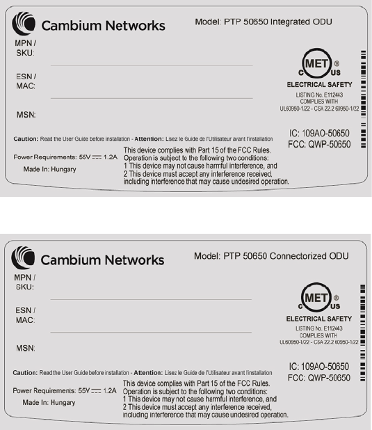
FCC identifiers are reproduced on the product labels for the FCC/IC regional variant (Figure 90 and
Figure 91).
Figure 90
FCC and IC certifications on integrated ODU product labels
Figure 91
FCC and IC certifications on connectorized ODU product labels
Industry Canada product labels
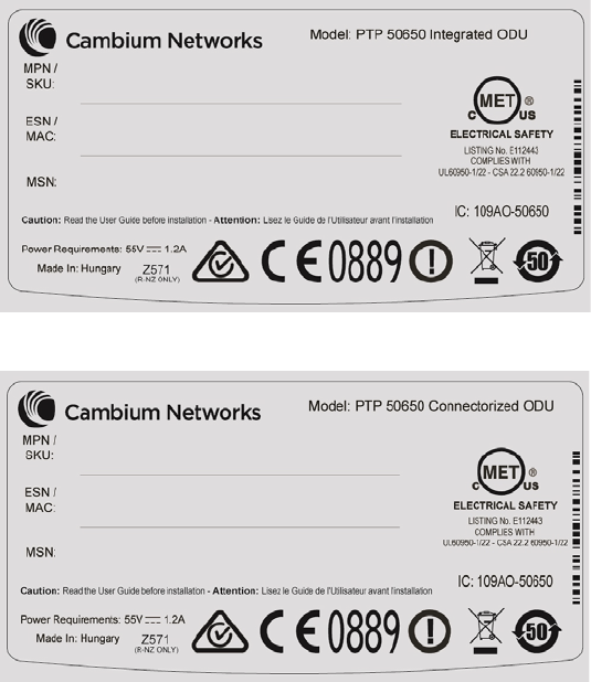
Industry Canada Certification Numbers are reproduced on the product labels for the FCC/IC
regional variant (Figure 90 and Figure 91) and also on the Rest of the World (RoW) regional variant
(Figure 92 and Figure 93).
UNDER DEVELOPMENT
Page 4-30
Chapter 4: Legal and regulatory information Compliance with radio regulations
Figure 92
IC certification on integrated ODU product labels
Figure 93
IC certification on connectorized ODU product labels
4.9 GHz FCC and IC notification
The system has been approved under FCC Part 90 and Industry Canada RSS-111 for Public Safety
Agency usage. The installer or operator is responsible for obtaining the appropriate site licenses
before installing or using the system.
Utilisation de la bande 4.9 GHz FCC et IC
Le système a été approuvé en vertu de FCC Part 90 et Industrie Canada RSS-111 pour l'utilisation
par l'Agence de la Sécurité publique. L'installateur ou l'exploitant est responsable de l'obtention
des licences de appropriées avant d'installer ou d'utiliser le système.
5.1 GHz FCC notification
This device complies with part 15E of the US FCC Rules and Regulations. Operation is subject to
the following two conditions: (1) This device may not cause harmful interference, and (2) This
device must accept any interference received, including interference that may cause undesired
operation.
UNDER DEVELOPMENT
Page 4-31
Chapter 4: Legal and regulatory information Compliance with radio regulations
For the connectorized version of the product and in order to reduce potential radio interference to
other users, the antenna type and its gain should be so chosen that the equivalent isotropically
radiated power (EIRP) is not more than that permitted by the regulations. The transmitted power
must be reduced to achieve this requirement.
5.2 GHz and 5.4 GHz FCC and IC notification
This device complies with part 15E of the US FCC Rules and Regulations and with Industry Canada
RSS-210 Annex 9. Operation is subject to the following two conditions: (1) This device may not
cause harmful interference, and (2) This device must accept any interference received, including
interference that may cause undesired operation. In Canada, users should be cautioned to take
note that high power radars are allocated as primary users (meaning they have priority) of 5250 –
5350 MHz and 5650 – 5850 MHz and these radars could cause interference and/or damage to
license-exempt local area networks (LELAN).
For the connectorized version of the product and in order to reduce potential radio interference to
other users, the antenna type and its gain should be so chosen that the equivalent isotropically
radiated power (EIRP) is not more than that permitted by the regulations. The transmitted power
must be reduced to achieve this requirement.
Utilisation de la bande 5.4 GHz FCC et IC
Cet appareil est conforme à la Section 15E de la réglementation FCC aux États-Unis et aux
règlementations et avec Industrie Canada RSS-210 Annexe 9. Son fonctionnement est soumis aux
deux conditions suivantes: (1) Ce dispositif ne doit pas causer d'interférences nuisibles, et (2) Cet
appareil doit tolérer toute interférence reçue, y compris les interférences pouvant entraîner un
fonctionnement indésirable. Au Canada, les utilisateurs doivent prendre garde au fait que les
radars à haute puissance sont considères comme les utilisateurs prioritaires de 5250 à 5350 MHz et
5650 à 5850 MHz et ces radars peuvent causer des interférences et / ou interférer avec un réseau
local ne nécessitant pas de licence.
Pour la version du produit avec antenne externe et afin de réduire le risque d'interférence avec
d'autres utilisateurs, le type d'antenne et son gain doivent être choisis afin que la puissance
isotrope rayonnée équivalente (PIRE) ne soit pas supérieure à celle permise par la règlementation.
Il peut être nécessaire de réduire la puissance transmise doit être réduite pour satisfaire cette
exigence.
5.8 GHz FCC notification
This device complies with part 15C of the US FCC Rules. Operation is subject to the following two
conditions: (1) This device may not cause harmful interference, and (2) This device must accept
any interference received, including interference that may cause undesired operation.
UNDER DEVELOPMENT
Page 4-32

Chapter 4: Legal and regulatory information Compliance with radio regulations
5.8 GHz IC notification
RSS-GEN issue 3 (7.1.3) Licence-Exempt Radio Apparatus:
This device complies with Industry Canada license-exempt RSS standard(s). Operation is
subject to the following two conditions: (1) this device may not cause interference, and (2) this
device must accept any interference, including interference that may cause undesired
operation of the device.
Le présent appareil est conforme aux CNR d'Industrie Canada applicables aux appareils radio
exempts de licence. L'exploitation est autorisée aux deux conditions suivantes : (1) l'appareil
ne doit pas produire de brouillage, et (2) l'utilisateur de l'appareil doit accepter tout brouillage
radioélectrique subi, même si le brouillage est susceptible d'en compromettre le
fonctionnement.
In Canada, high power radars are allocated as primary users (meaning they have priority) of the
5650 – 5850 MHz spectrum. These radars could cause interference or damage to license-exempt
local area network (LE-LAN) devices.
Au Canada, les radars à haute puissance sont désignés comme utilisateurs principaux (ils ont la
priorité) de la 5650 - spectre 5850 MHz. Ces radars peuvent causer des interférences et / ou
interférer avec un réseau local ne nécessitant pas de licence.
5.1 GHz band edge channel power reduction
Equivalent isotropic radiated power (EIRP) is restricted in edge channels when the PTP 650 is
operated the 5.1 GHz band with the USA country license. The amount of EIRP reduction has been
determined during regulatory testing and cannot be changed by professional installers or end
users. Units intended for the USA market are locked for use in the USA and cannot be operated
under the regulations for other regulatory domains.
The PTP 650 takes into account the antenna gain and cable loss configured by the professional
installer in the web-based interface to limit the EIRP to ensure regulatory compliance. No
additional action is required by the installer to reduce transmitter power in band edge channels.
The maximum EIRP in band edge channels for the USA 5.1 GHz band is listed in Table 109.
Table 109
Edge channel power reduction in regulatory band 84
Channel Bandwidth
Channel Frequency
Maximum EIRP
5 MHz Below 5158 MHz 26 dBm
5158 to 5200 MHz 30 dBm
Above 5200 MHz 33 dBm
10 MHz Below 5164 23 dBm
5164 and above 31 dBm
15 MHz Below 5170 23 dBm
5170 to 5181 31 dBm
Above 5181 37 dBm
UNDER DEVELOPMENT
Page 4-33

Chapter 4: Legal and regulatory information Compliance with radio regulations
Channel Bandwidth
Channel Frequency
Maximum EIRP
20 MHz Below 5175 23 dBm
5175 to 5187 30 dBm
Above 5187 36 dBm
30 MHz Below 5187 24 dBm
5187 to 5200 30 dBm
Above 5200 35 dBm
40 MHz Below 5200 24 dBm
5200 and above 30 dBm
45 MHz Below 5205 23 dBm
5205 and above 30 dBm
5.2 GHz band edge channel power reduction
Equivalent isotropic radiated power (EIRP) is restricted in edge channels when the PTP 650 is
operated the 5.2 GHz band with the USA or Canada country license. The amount of EIRP reduction
has been determined during regulatory testing and cannot be changed by professional installers or
end users. Units intended for the USA and Canada market are locked for use in the USA or Canada
and cannot be operated under the regulations for other regulatory domains.
The PTP 650 takes into account the antenna gain and cable loss configured by the professional
installer in the web-based interface to limit the EIRP to ensure regulatory compliance. No
additional action is required by the installer to reduce transmitter power in band edge channels.
The maximum EIRP in band edge channels for the USA and Canada 5.2 GHz band is listed in Table
110.
Table 110
Edge channel power reduction in regulatory band 38
Channel Bandwidth
Channel Frequency
Maximum EIRP
5 MHz Below 5256.0 MHz 24 dBm
Above 5344.0 MHz 24 dBm
10 MHz Below 5260.0 MHz 23 dBm
Above 5337.0 MHz 23 dBm
15 MHz Below 5267.0 MHz 22 dBm
Above 5330.0 MHz 22 dBm
20 MHz Below 5271.0 MHz 25 dBm
UNDER DEVELOPMENT
Page 4-34

Chapter 4: Legal and regulatory information Compliance with radio regulations
Channel Bandwidth
Channel Frequency
Maximum EIRP
Above 5325.0 MHz 21 dBm
30 MHz Below 5280.0 MHz 25 dBm
Above 5308.0 MHz 23 dBm
40 MHz Below 5290.0 MHz 24 dBm
Above 5299.0 MHz 20 dBm
45 MHz Below 5295.0 MHz 24 dBm
Above 5295.0 MHz 20 dBm
5.4 GHz band edge channel power reduction
Equivalent isotropic radiated power (EIRP) is restricted in edge channels when the PTP 650 is
operated the 5.4 GHz band with the USA or Canada country license. The amount of EIRP reduction
has been determined during regulatory testing and cannot be changed by professional installers or
end users. Units intended for the USA and Canada market are locked for use in the USA or Canada
and cannot be operated under the regulations for other regulatory domains.
The PTP 650 takes into account the antenna gain and cable loss configured by the professional
installer in the web-based interface to limit the EIRP to ensure regulatory compliance. No
additional action is required by the installer to reduce transmitter power in band edge channels.
The maximum EIRP in band edge channels for the USA and Canada 5.4 GHz band is listed in Table
111.
Réduction de puissance aux bords de la bande 5.4 GHz
La Puissance isotrope rayonnée équivalente (PIRE) est limitée dans les canaux en bord de la
bandes lorsque le PTP 650 est configuré pour utiliser la band 5,4 GHz aux les Etats-Unis ou au
Canada. La réduction de la PIRE a été déterminée lors de tests réglementaires et ne peut être
changée par des installateurs professionnels ou les utilisateurs. Les PTP 650 destinées aux USA et
Canada sont limitées pour opérer exclusivement aux États-Unis ou au Canada et ne peuvent pas
être configurés pour adhérer à la réglementation d’autres pays.
Le PTP 650 prend en compte le gain de l'antenne et les pertes des câbles de connexion configurés
par l'installateur professionnel via l'interface graphique pour limiter la PIRE pour assurer la
conformité à la réglementation en vigueur. Aucune action supplémentaire n'est requise par
l'installateur afin de réduire la puissance d'émission dans les canaux aux bords de bande.
La PIRE maximale dans les canaux aux bords de bande 5,4 GHz pour les Etats-Unis et le Canada
est listée dans la Table 111.
UNDER DEVELOPMENT
Page 4-35

Chapter 4: Legal and regulatory information Compliance with radio regulations
Table 111
Edge channel power reduction in regulatory bands 12 and 13
Channel Bandwidth
Channel Frequency
Maximum EIRP
5 MHz Below 5476.0 MHz 24 dBm
Above 5720.0 MHz 24 dBm
10 MHz Below 5478.0 MHz 27 dBm
Above 5715.0 MHz 25 dBm
15 MHz Below 5480.0 MHz 29 dBm
Above 5709.0 MHz 26 dBm
20 MHz Below 5482.0 MHz 30 dBm
Above 5704.0 MHz 23 dBm
30 MHz Below 5492.0 MHz 27 dBm
Above 5694.0 MHz 25 dBm
40 MHz Below 5500.0 MHz 28 dBm
Above 5691.0 MHz 24 dBm
45 MHz Below 5508.0 MHz 24 dBm
Above 5686.0 MHz 22 dBm
5.8 GHz band edge channel power reduction
Transmitter power is restricted in edge channels when the PTP 650 is operated the 5.8 GHz band
with the USA or Canada country license. The amount of transmitter power reduction has been
determined during regulatory testing and cannot be changed by professional installers or end
users. Units intended for the USA and Canada market are locked for use in the USA or Canada and
cannot be operated under the regulations for other regulatory domains.
The maximum transmitter power in band edge channels for the FCC 5.8 GHz band is listed in Table
112.
Réduction de puissance aux bords de la bande 5.8 GHz
La Puissance isotrope rayonnée équivalente (PIRE) est limitée dans les canaux en bord de la
bandes lorsque le PTP 650 est configuré pour utiliser la band 5,8 GHz aux les Etats-Unis ou au
Canada. La réduction de la PIRE a été déterminée lors de tests réglementaires et ne peut être
changée par des installateurs professionnels ou les utilisateurs. Les PTP 650 destinées aux USA et
Canada sont limitées pour opérer exclusivement aux États-Unis ou au Canada et ne peuvent pas
être configurés pour adhérer à la réglementation d’autres pays.
UNDER DEVELOPMENT
Page 4-36

Chapter 4: Legal and regulatory information Compliance with radio regulations
La PIRE maximale dans les canaux aux bords de bande 5,4 GHz pour les Etats-Unis et le Canada
est listée dans la Table 112.
Table 112
Edge channel power reduction in regulatory band 1
Channel Bandwidth
Channel Frequency
Maximum conducted power
5 MHz Below 5733.0 MHz 24 dBm
Above 5838.0 MHz 24 dBm
10 MHz Below 5737.0 MHz 25 dBm
Above 5837.0 MHz 25 dBm
15 MHz Below 5740.0 MHz 25 dBm
Above 5835.0 MHz 25 dBm
20 MHz Below 5742.0 MHz 25 dBm
Above 5832.0 MHz 25 dBm
30 MHz Below 5752.0 MHz 25 dBm
Above 5822.0 MHz 25 dBm
40 MHz Below 5765.0 MHz 25 dBm
Above 5810.0 MHz 25 dBm
45 MHz Below 5778.0 MHz 23 dBm
Above 5795.0 MHz 22 dBm
Selection of antennas
For guidance on the selection of dedicated external antennas refer to Choosing external antennas
on page 3-29.
For a list of antennas submitted to the FCC and IC for use with the PTP 650 refer to FCC and IC
approved antennas on page 2-22.
UNDER DEVELOPMENT
Page 4-37
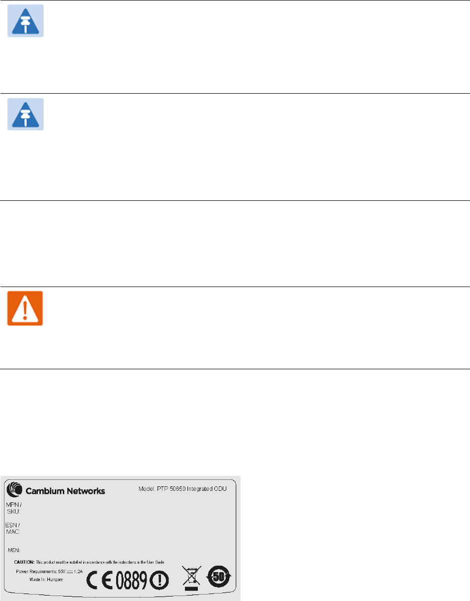
Chapter 4: Legal and regulatory information Compliance with radio regulations
Note
Under Industry Canada regulations, this radio transmitter may only operate using an
antenna of a type and maximum (or lesser) gain approved for the transmitter by
Industry Canada. To reduce potential radio interference to other users, the antenna
type and its gain should be so chosen that the equivalent isotropically radiated power
(EIRP) is not more than that necessary for successful communication.
Remarque
Conformément à la réglementation d'Industrie Canada, le présent émetteur radio peut
fonctionner avec une antenne d'un type et d'un gain maximal (ou inférieur) approuvé
pour l'émetteur par Industrie Canada. Dans le but de réduire les risques de brouillage
radioélectrique à l'intention des autres utilisateurs, il faut choisir le type d'antenne et
son gain de sorte que la puissance isotrope rayonnée équivalente (p.i.r.e.) ne dépasse
pas l'intensité nécessaire à l'établissement d'une communication satisfaisante.
European Union compliance
The PTP 650 complies with the regulations that are in force in the European Union.
Warning
This is a Class A product. In a domestic environment this product may cause radio
interference, in which case the user may be required to take adequate measures.
If this equipment does cause interference to radio or television reception, refer to
Radio and television interference on page 8-9 for corrective actions.
EU product labels
The European R&TTE directive 1999/5/EC Certification Number is reproduced on the product labels
(Figure 94 and Figure 95).
Figure 94
European Union certification on integrated product label
UNDER DEVELOPMENT
Page 4-38
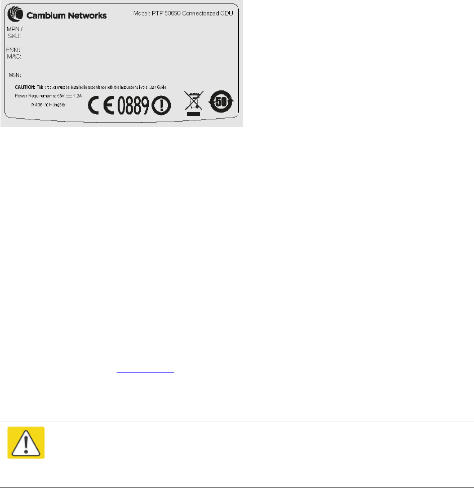
Chapter 4: Legal and regulatory information Compliance with radio regulations
Figure 95
European Union certification on connectorized product label
5.4 GHz European Union notification
The PTP 650 product is a two-way radio transceiver suitable for use in Broadband Wireless Access
System (WAS), Radio Local Area Network (RLAN), or Fixed Wireless Access (FWA) systems. It is a
Class 1 device and uses operating frequencies that are harmonized throughout the EU member
states. The operator is responsible for obtaining any national licenses required to operate this
product and these must be obtained before using the product in any particular country.
Hereby, Cambium Networks declares that the PTP 650 product complies with the essential
requirements and other relevant provisions of Directive 1999/5/EC. The declaration of conformity
may be consulted at the support website (see Contacting Cambium Networks on page 1).
5.8 GHz European Union notification
The PTP 650 is a Class 2 device as it operates on frequencies that are not harmonized across the
EU. Currently the product may only be operated in the countries listed in Table 108. However, the
regulatory situation in Europe is changing and the radio spectrum may become available in other
countries in future. See www.ero.dk for further information. The operator is responsible for
obtaining any national licenses required to operate this product and these must be obtained before
using the product in any particular country.
Caution
This equipment operates as a secondary application, so it has no rights against
harmful interference, even if generated by similar equipment, and must not cause
harmful interference on systems operating as primary applications.
Hereby, Cambium Networks declares that the PTP 650 product complies with the essential
requirements and other relevant provisions of Directive 1999/5/EC. The declaration of conformity
may be consulted at the support website (see Contacting Cambium Networks on page 1).
UNDER DEVELOPMENT
Page 4-39
Chapter 4: Legal and regulatory information Compliance with radio regulations
5.8 GHz operation in the UK
The PTP 650 Connectorized product has been notified for operation in the UK, and when operated
in accordance with instructions for use it is compliant with UK Interface Requirement IR2007. For
UK use, installations must conform to the requirements of IR2007 in terms of EIRP spectral density
against elevation profile above the local horizon in order to protect Fixed Satellite Services. The
frequency range 5795-5815 MHz is assigned to Road Transport & Traffic Telematics (RTTT) in the
U.K. and shall not be used by FWA systems in order to protect RTTT devices. UK Interface
Requirement IR2007 specifies that radiolocation services shall be protected by a Dynamic
Frequency Selection (DFS) mechanism to prevent co-channel operation in the presence of radar
signals.
UNDER DEVELOPMENT
Page 4-40

Chapter 5: Installation
This chapter describes how to install and test the hardware for a PTP 650 link. It contains the
following topics:
• Safety on page 5-2 contains important safety guidelines that must be observed by personnel
installing or operating PTP 650 equipment.
• ODU variants and mounting bracket options on page 5-6 provides details of six different
bracket options, including the type of ODu and range of pole diameters supported by each
option.
• Installing the ODU and top LPU on page 5-7 describes how to mount and ground an integrated
or connectorized ODU, how to mount and ground the top LPU.
• Install external antennas for a connectorized ODU on page 5-16 describes how to mount and
connect an external antenna for the connectorized ODU.
• Installing the copper Cat5e Ethernet interface on page 5-18 describes how to install the copper
Cat5e power over Ethernet interface from the ODU (PSU port) to the PSU.
• Installing the PSU on page 5-26 describes how to install a power supply unit for the PTP 650,
either the AC Power Injector or the AC+DC Enhanced Power Injector.
• Installing a PTP-SYNC unit on page 5-28 describes how to install a PTP-SYNC unit for TDD
synchronization.
• Installing a GPS receiver on page 5-32 describes how to install a GPS receiver as the timing
reference source for PTP-SYNC.
• Installing a NIDU on page 5-42 describes how to install a network indoor unit (NIDU) for TDM
(T1 or E1) interfaces.
• Installing an SFP Ethernet interface on page 5-28 describes how to install an optical or copper
Cat5e Ethernet interface from the ODU (SFP port) to a connected device.
• Installing an Aux Ethernet interface on page 5-57 describes how to install a copper Cat5e
Ethernet interface from the ODU (Aux port) to a connected device.
• Supplemental installation information on page 5-58 contains detailed installation procedures
that are not included in the above topics, such as how to strip cables, create grounding points
and weatherproof connectors.
Note
These instructions assume that LPUs are being installed from the PTP 650 LPU and
grounding kit (Cambium part number C000065L007). If the installation does not
require LPUs, adapt these instructions as appropriate.
If LPUs are being installed, only use the five black-capped EMC cable glands supplied
in the LPU and grounding kit. The silver-capped cable glands supplied in the ODU kits
must only be used in PTP 650 installations which do not require LPUs.
UNDER DEVELOPMENT
Page 5-1

Chapter 5: Installation Safety
Safety
Warning
To prevent loss of life or physical injury, observe the following safety guidelines. In no
event shall Cambium Networks be liable for any injury or damage caused during the
installation of the Cambium PTP 650. Ensure that only qualified personnel install a PTP
650 link.
Power lines
Exercise extreme care when working near power lines.
Working at heights
Exercise extreme care when working at heights.
PSU
Always use one of the Cambium PTP 650 Series power supply units (PSU) to power the ODU.
Failure to use a Cambium supplied PSU could result in equipment damage and will invalidate the
safety certification and may cause a safety hazard.
Grounding and protective earth
The Outdoor Unit (ODU) must be properly grounded to protect against lightning. It is the user’s
responsibility to install the equipment in accordance with national regulations. In the USA follow
the requirements of the National Electrical code NFPA 70-2005 and 780-2004 Installation of
Lightning Protection Systems. In Canada, follow Section 54 of the Canadian Electrical Code. These
codes describe correct installation procedures for grounding the outdoor unit, mast, lead-in wire
and discharge unit, size of grounding conductors and connection requirements for grounding
electrodes. Other regulations may apply in different countries and therefore it is recommended
that installation of the outdoor unit be contracted to a professional installer.
UNDER DEVELOPMENT
Page 5-2
Chapter 5: Installation Safety
DC supply
To power the ODU from a DC supply, use the AC+DC Enhanced Power Injector (PSU) (Cambium
part number C000065L002). Ensure that the DC power supply meets the requirements specified in
PSU DC power supply on page 3-15.
Powering down before servicing
Before servicing PTP 650 equipment, always switch off the power supply and unplug it from the
PSU.
Do not disconnect the RJ45 drop cable connectors from the ODU while the PSU is connected to the
power supply. Always remove the AC or DC input power from the PSU.
Primary disconnect device
The main power supply is the primary disconnect device. The AC+DC Enhanced power injector is
fused on the DC input. Some installations will also require an additional circuit breaker or isolation
switch to be fitted in the DC supply.
External cables
Safety may be compromised if outdoor rated cables are not used for connections that will be
exposed to the outdoor environment. For outdoor copper Cat5e Ethernet interfaces, always use
Cat5e cable that is gel-filled and shielded with copper-plated steel. Alternative types of drop cable
are not supported by Cambium Networks.
Drop cable tester
The PSU output voltage may be hazardous in some conditions, for example in wet weather. Do
NOT connect the drop cable tester to the PSU, either directly or via LPUs.
Grounding PTP-SYNC
In order to meet the safety requirements for deployment in Australia and New Zealand
(AS/NZS 60950-1), the PTP-SYNC unit, if deployed, must be grounded to a Protective Ground in
accordance with Local Electrical Regulations.
UNDER DEVELOPMENT
Page 5-3
Chapter 5: Installation Safety
RF exposure near the antenna
Strong radio frequency (RF) fields will be present close to the antenna when the transmitter is on.
Always turn off the power to the ODU before undertaking maintenance activities in front of the
antenna.
Minimum separation distances
Ensure that personnel are not exposed to unsafe levels of RF energy. The units start to radiate RF
energy as soon as they are powered up. Never work in front of the antenna when the ODU is
powered. Install the ODUs so as to provide and maintain the minimum separation distances from
all persons. For minimum separation distances, see Calculated distances on page 4-24.
Grounding and lightning protection requirements
Ensure that the installation meets the requirements defined in Grounding and lightning protection
on page 3-11.
Grounding cable installation methods
To provide effective protection against lightning induced surges, observe these requirements:
• Grounding conductor runs are as short, straight and smooth as possible, with bends and
curves kept to a minimum.
• Grounding cables must not be installed with drip loops.
• All bends must have a minimum radius of 200 mm (8 in) and a minimum angle of 90°. A
diagonal run is preferable to a bend, even though it does not follow the contour or run parallel
to the supporting structure.
• All bends, curves and connections must be routed towards the grounding electrode system,
ground rod, or ground bar.
• Grounding conductors must be securely fastened.
• Braided grounding conductors must not be used.
• Approved bonding techniques must be used for the connection of dissimilar metals.
Siting ODUs and antennas
ODUs, external antennas and GPS receivers for PTP-SYNC are not designed to survive direct
lightning strikes. For this reason they must be installed in Zone B as defined in Lightning
protection zones on page 3-11. Mounting in Zone A may put equipment, structures and life at risk.
UNDER DEVELOPMENT
Page 5-4

Chapter 5: Installation Safety
Thermal Safety
The ODU enclosure may be hot to the touch when in operation. The ODU must not be operated in
ambient temperatures exceeding 40°C unless mounted in a Restricted Access Location. For more
information, see ODU ambient temperature limits on page 3-13.
Warning
Do not install the ODU in a location where the ambient temperature could exceed 40°C
unless this is a Restricted Access Location as defined by EN 60950-1.
Alerte
L’unité externe ne doit pas être installée dans un endroit où la température ambiante
est supérieure à 40C à moins que l’accès soit limité au personnel autorisé.
UNDER DEVELOPMENT
Page 5-5

Chapter 5: Installation ODU variants and mounting bracket options
ODU variants and mounting bracket options
Mounting bracket options
The PTP 650 series supports five mounting bracket options. Select the optimum mounting bracket
arrangement based on the pole diameter and the ODU variant:
Table 113
ODU mounting bracket part numbers
Bracket
Pole diameter
ODU variants
Bracket part
number
Mounting bracket
(integrated)
40 mm to 82 mm
(1.6 inches to 3.2 inches)
PTP 650 Integrated
PTP 650S Integrated
PTP 650L Integrated
N000065L031
Mounting bracket
(connectorized)
40 mm to 82 mm
(1.6 inches to 3.2 inches)
PTP 650 Connectorized N000065L032
Extended integrated
mounting bracket
89 mm OR 114 mm
(3.5 inches OR 4.5 inches)
PTP 650 Integrated
PTP 650S Integrated
PTP 650L Integrated
PTP 650 Connectorized
N000065L030
Mounting bracket
(integrated) with large
diameter extension kit
89 mm to 229 mm
(3.5 inches to 9.0 inches)
PTP 650 Integrated
PTP 650S Integrated
PTP 650L Integrated
PTP 650 Connectorized
N000065L031
with
N000065L042
Low profile bracket 40 mm to 82 mm
(1.6 inches to 3.2 inches)
PTP 650S Integrated
PTP 650L Integrated
N000065L039
89 mm to 229 mm
(3.5 inches to 9.0 inches)
The low profile bracket provides elevation adjustment with the PTP 650S and PTP 650L Integrated
ODUs of +10° to –5° or +5° to –10°. A larger adjustment range is available using the standard
integrated mounting bracket. The connectorized mounting bracket does not provide elevation
adjustment.
Note
The connectorized mounting bracket is included with the PTP 650 Connectorized ODU.
Order a bracket separately for PTP 650 or PTP 650S Integrated or PTP 650L Integrated
ODUs.
UNDER DEVELOPMENT
Page 5-6
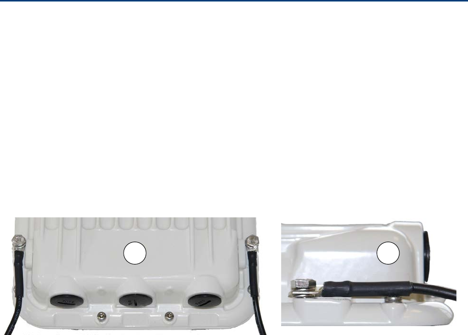
Chapter 5: Installation Installing the ODU and top LPU
Installing the ODU and top LPU
To install the ODU and top LPU, use the following procedures:
• Attach ground cables to the ODU on page 5-7
• Mount the ODU on the mast on page 5-7
• Mount the top LPU on page 5-14
• Interconnect and ground the ODU and top LPU on page 5-14
Attach ground cables to the ODU
1
Fasten one ground cable to each ODU grounding point
using the M6 (small) lugs: one is for the
top LPU (M6 lug at other end) and the other is for the tower or building (M10 lug at other end).
It does not matter which cable goes on which ODU grounding point.
2
T
ighten both ODU grounding bolts to a torque of 5 Nm (3.9 lb ft).
Mount the ODU on the mast
Select the most appropriate bracket mounting arrangement from the options listed in Mounting
bracket options on page 5-6. Refer to individual procedures below for each of the options:
• Mounting bracket (integrated) on page 5-8
• Mounting bracket (connectorized) on page 5-9
• Extended integrated mounting bracket on page 5-10
• Mounting bracket (integrated) with large diameter extension kit on page 5-11
• Low profile bracket on small diameter pole on page 5-12
• Low profile bracket on large pole on page 5-13
The procedure for the Mounting bracket (connectorized) can be readily adapted to attach the ODU
to a horizontal pole of similar size.
The procedure for the Mounting bracket (integrated) and the Extended integrated mounting
bracket can be adapted to attach the ODU to a suitable horizontal pole, but the adjustment of
azimuth angle is necessarily limited compared with an installation on a vertical pole.
2
1
UNDER DEVELOPMENT
Page 5-7
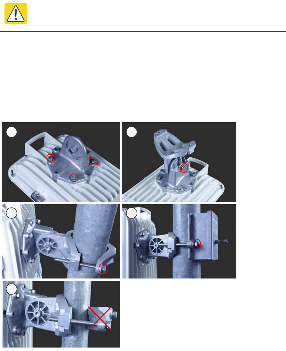
Chapter 5: Installation Installing the ODU and top LPU
Mounting bracket (integrated)
Caution
Do not reverse the bracket clamp, as this arrangement may lead to failure of the
assembly. Do not over-tighten the bolts as this may lead to failure of the assembly.
1
Fix the mounting plate to the back of the ODU using the four bolts, and spring and plain
washers provided. Tighten the bolts to a torque setting of 5.0 Nm (3.7 lb ft).
2
Attach the bracket body to the mounting plate using the M8 bolt, spring and plain washers.
3
Hoist the ODU to the mounting position.
4
Attach the bracket body to the pole using the bracket clamp, M8 bolts, and spring and plain
washers. For back-to-back mounting, use the LPU in place of the clamp.
5
Adjust the elevation and azimuth to achieve visual alignment. Tighten all three bracket bolts to
a torque of 8.0 Nm (6.0 lb ft).
1 2
4 5
7
UNDER DEVELOPMENT
Page 5-8
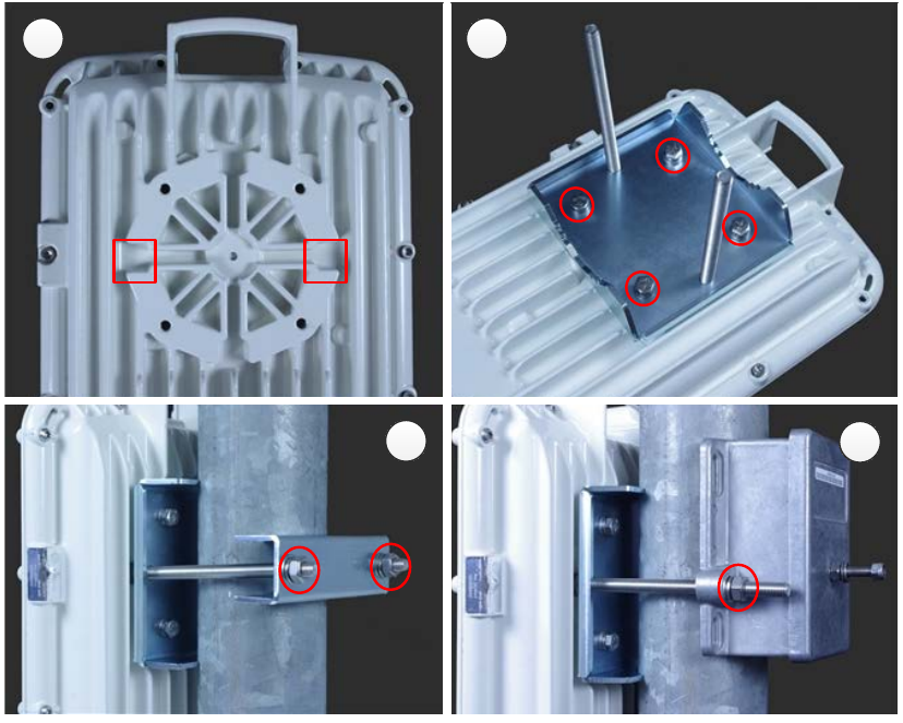
Chapter 5: Installation Installing the ODU and top LPU
Mounting bracket (connectorized)
1
Identify the square cavities in the casting on the back of the ODU. These cavities will be used
to accommodate the heads of two M8 bracket bolts.
2
Fix the mounting plate to the ODU using the four M6 bolts, and spring and plain washers
provided. Ensure that the M8 bolts are correctly held between the mounting plate and the
ODU. Tighten the M6 bolts to a torque setting of 5.0 Nm (3.7 lb ft).
3
Hoist the ODU to the mounting position.
4
Attach the bracket body to the pole using the bracket clamp, spring and plain washers, and M8
nuts.
5
Alternatively, use the LPU in place of the clamp to provide a back-to-back arrangement.
6
Tighten the two M8 bracket bolts to a torque setting of 8.0 Nm (6.0 lb ft). Do not over-tighten
the bolts as this may lead to failure of the assembly.
1 2
45
UNDER DEVELOPMENT
Page 5-9
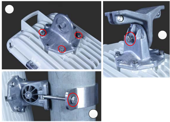
Chapter 5: Installation Installing the ODU and top LPU
Extended integrated mounting bracket
1
Fix the mounting plate to the back of the ODU using the four M6 bolts, and spring and plain
washers provided. Tighten the bolts to a torque setting of 5.0 Nm (3.7 lb ft). The step is common
with the standard integrated bracket.
2
Attach the bracket body of the extended bracket on the mounting plate on the ODU to using the
M8 bolt and spring and plain washer.
3
Hoist the ODU to the mounting position.
4
Select the correct clamp. The larger clamp is intended for poles of diameter 114 mm (4.5
inches). The smaller clamp is intended for poles of diameter 89 mm (3.5 inches).
5
Attach the bracket body to the pole using the selected bracket clamp, washers and M8 bolts.
6
Adjust the elevation and azimuth to achieve visual alignment. Tighten all three M8 bracket bolts
to a torque setting of 8.0 Nm (6.0 lb ft). Do not over-tighten the bolts as this may lead to failure
of the assembly.
1
2
5
UNDER DEVELOPMENT
Page 5-10
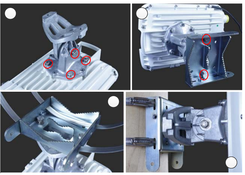
Chapter 5: Installation Installing the ODU and top LPU
Mounting bracket (integrated) with large diameter extension kit
1
Fix the mounting plate to the back of the ODU using the bolts and washers provided. Tighten
the four bolts to a torque setting of 5.0 Nm (3.7 lb ft). Attach the bracket body to the mounting
plate using the M8 bolt and spring and plain washer. This is equivalent to the first two steps for
the standard integrated bracket.
2
Attach the adaptor plate of the large diameter extension kit to the bracket body using the bolts
and washers provided. Tighten the two bolts to a torque setting of 5.0 Nm (3.7 lb ft).
3
Feed the Jubilee straps through the slots in the adaptor plate.
4
Hoist the ODU to the mounting position.
5
Attach the adaptor plate to the pole using the Jubilee straps.
6
Adjust the azimuth to achieve visual alignment. Tighten the Jubilee straps to a torque setting of
6.0 Nm (4.5 lb ft).
7
Adjust the elevation to achieve visual alignment. Tighten M8 bracket bolt to a torque setting of
8.0 Nm (6.0 lb ft). Do not over-tighten this bolt as this may lead to failure of the assembly.
1 2
3
5
UNDER DEVELOPMENT
Page 5-11
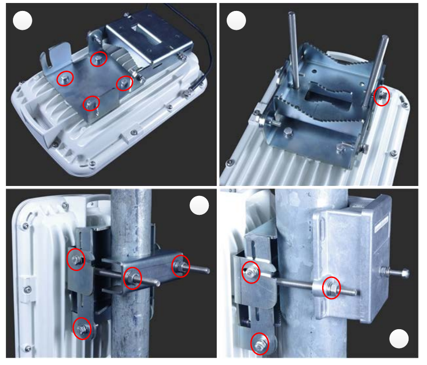
Chapter 5: Installation Installing the ODU and top LPU
Low profile bracket on small diameter pole
1
Fix the low profile bracket to the back of the ODU using the M6 bolts and washers provided.
Tighten the four bolts to a torque setting of 5.0 Nm (3.7 lb ft).
2
Pass the M8 coach bolts through the square holes in the hinged portion of the bracket. Close the
bracket. Two M6 bolts should pass through slots in the fixed portion of the bracket. Ensure that
the spring and plain washers of the M6 bolts are on the outside of the bracket assembly. Tighten
the four M6 bolts to ensure that the bracket cannot open accidentally.
3
Hoist the ODU to the mounting position.
4
Attach the bracket to the pole using the bracket clamp, washers and M8 nuts.
5
Alternatively, use the LPU in place of the clamp to provide a back-to-back arrangement.
6
Adjust the azimuth to achieve visual alignment. Tighten the two M8 bracket nuts to a torque
setting of 8.0 Nm (6.0 lb ft). Do not over-tighten these nuts as this may lead to failure of the
assembly.
7
Adjust the elevation to achieve visual alignment. Tighten the four M6 bolts to a torque setting of
5.0 Nm (3.7 lb ft).
1 2
4
5
UNDER DEVELOPMENT
Page 5-12
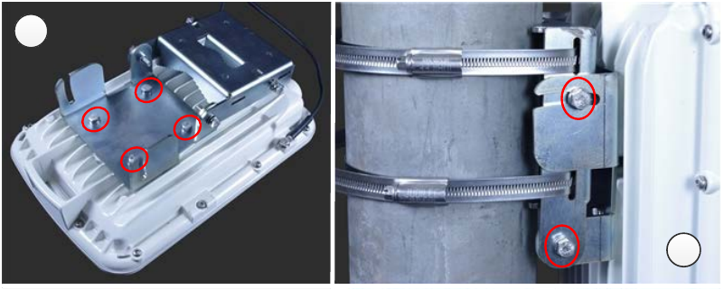
Chapter 5: Installation Installing the ODU and top LPU
Low profile bracket on large pole
1
Fix the low profile bracket to the back of the ODU using the M6 bolts and washers provided.
Tighten the four bolts to a torque setting of 5.0 Nm (3.7 lb ft). This step is common with the low
profile bracket on a smaller diameter pole.
2
Close the bracket. Two M6 bolts should pass through slots in the fixed portion of the bracket.
Ensure that the spring and plain washers of the M6 bolts are on the outside of the bracket
assembly. Tighten the four M6 bolts to ensure that the bracket cannot open accidentally. Feed
the Jubilee straps through the slots in the adaptor plate. This is similar to the procedure for the
large diameter extension kit.
3
Hoist the ODU to the mounting position.
4
Attach the bracket to the pole using the Jubilee straps.
5
Adjust the azimuth to achieve visual alignment. Tighten the Jubilee straps to a torque setting of
6.0 Nm (4.5 lb ft).
6
Adjust the elevation to achieve visual alignment. Tighten the four M6 bolts to a torque setting of
5.0 Nm (3.7 lb ft).
1
4
UNDER DEVELOPMENT
Page 5-13
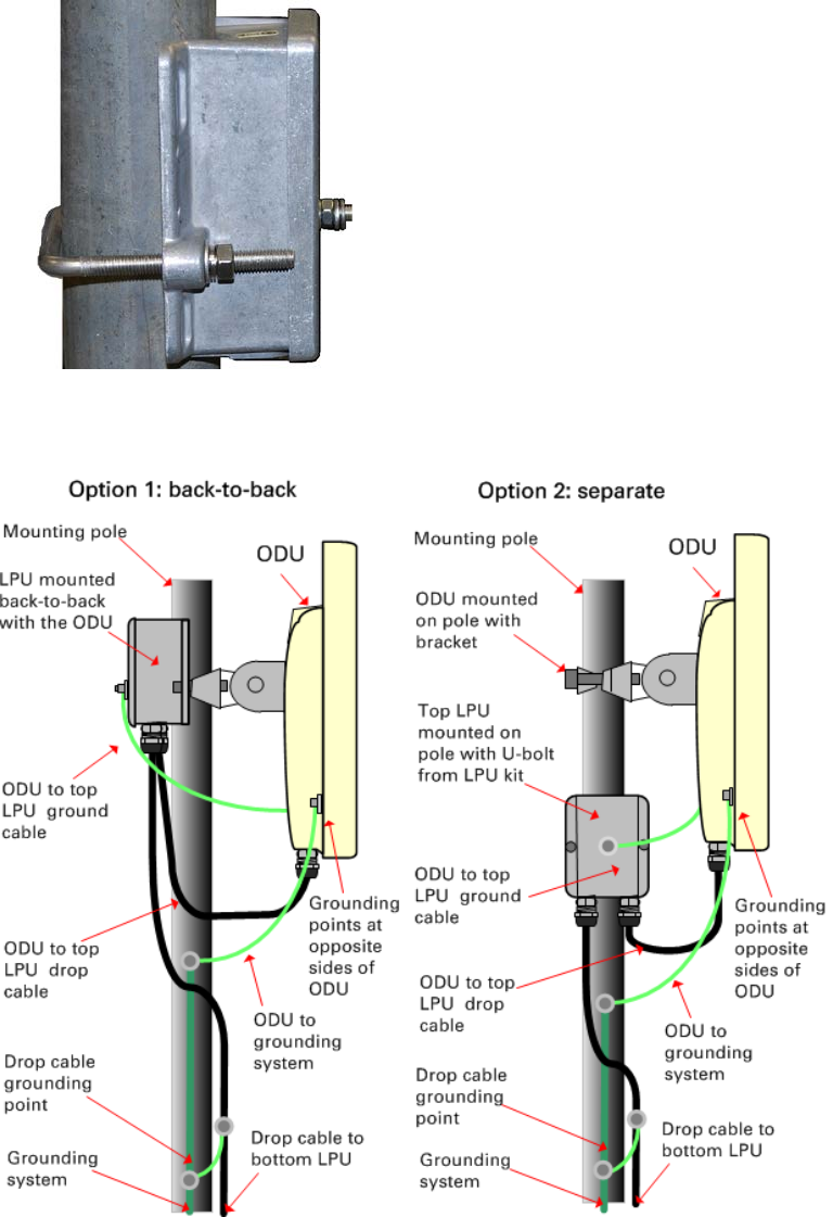
Chapter 5: Installation Installing the ODU and top LPU
Mount the top LPU
1
For separate LPU mounting,
use the U-bolt bracket from the LPU kit to mount the top LPU on the
pole below the ODU. Tighten
to a torque setting of 7.0 Nm (5.2 lb ft):
Interconnect and ground the ODU and top LPU
UNDER DEVELOPMENT
Page 5-14
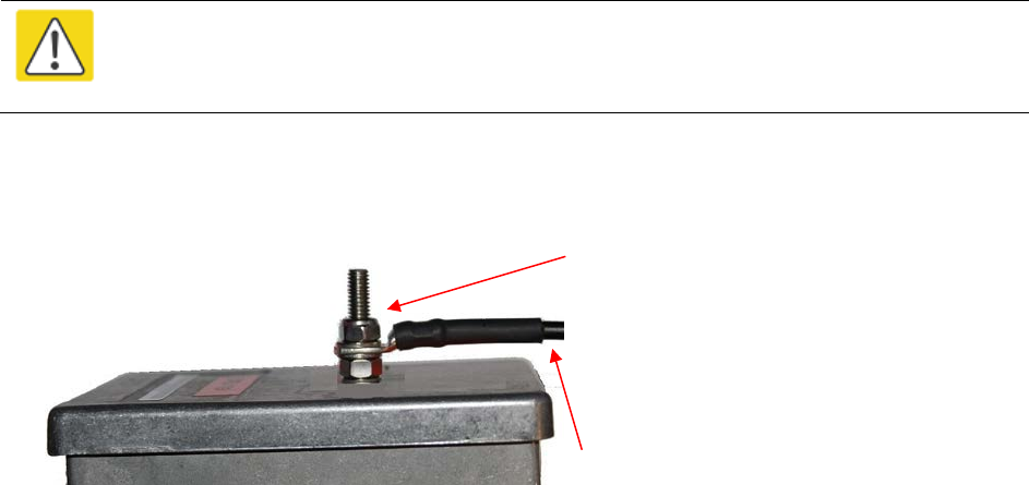
Chapter 5: Installation Installing the ODU and top LPU
Caution
Do not attach grounding cables to the ODU mounting bracket bolts, as this
arrangement will not provide full protection.
1
Fasten the ODU grounding cable to the top LPU using the M6 (small) lug.
Tighten both nuts to a
torque of 5
Nm (3.9 lb ft):
Locking nut
Washer
M6 lug
Washer
Nut
Toothed washer
M6 lug to ODU
2
Select a tower or building grounding point within 0.3 meters (1 ft) of the ODU bracket. Remove
paint from the surface and apply anti-oxidant compound. Fasten the ODU grounding cable to this
point using the M10 (large) lug.
3
If local regulations mandate the independent grounding of all devices,
add a third ground cable to
connect the top LPU directly to the grounding system.
UNDER DEVELOPMENT
Page 5-15
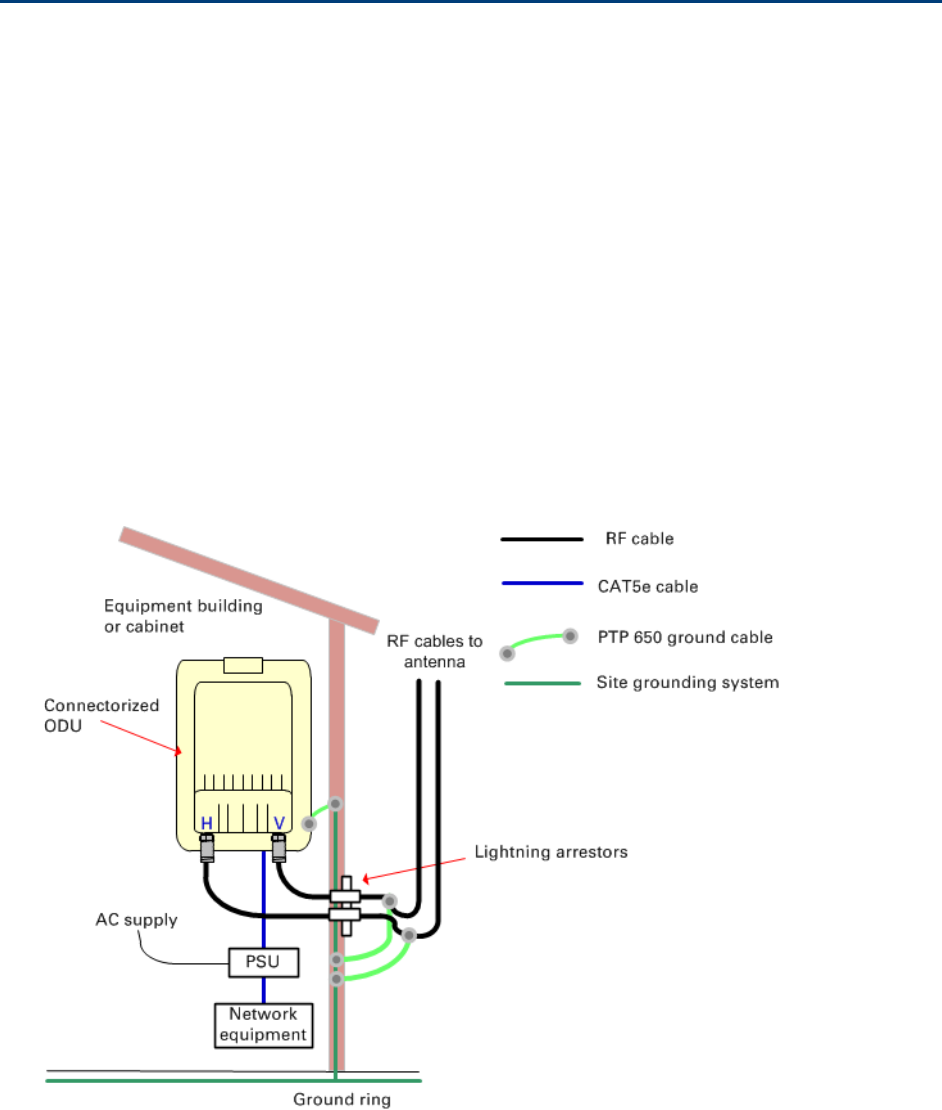
Chapter 5: Installation Install external antennas for a connectorized ODU
Install external antennas for a connectorized ODU
To mount and connect an external antenna for the connectorized ODU, proceed as follows:
1
M
ount the antenna(s) according to manufacturer’s instructions.
When using separate antennas to
achieve spatial diversity, mount
one with Horizontal polarization and the other with Vertical
polarization.
2
Connect the ODU V and H interfaces to the antenna(s) with RF cable of type
LMR-400 (Cambium
part numbers 30010194001 and 30010195001) and
N type connectors (Cambium part number
09010091001). Tighten the
N type connectors to a torque setting of 1.7 Nm (1.3 lb ft).
3
If
the ODU is mounted indoors, install lightning arrestors at the building entry point:
4
Form
drip loops near the lower ends of the antenna cables. These ensure that water is not
channeled towards the connector
s.
5
If the ODU is mounted outdo
ors, weatherproof the N type connectors (when antenna alignment
is complete) using PVC tape and
self-amalgamating rubber tape.
6
Weatherproof the antenna connectors in the same way (unless the antenna manufacturer
specifies a different method).
UNDER DEVELOPMENT
Page 5-16
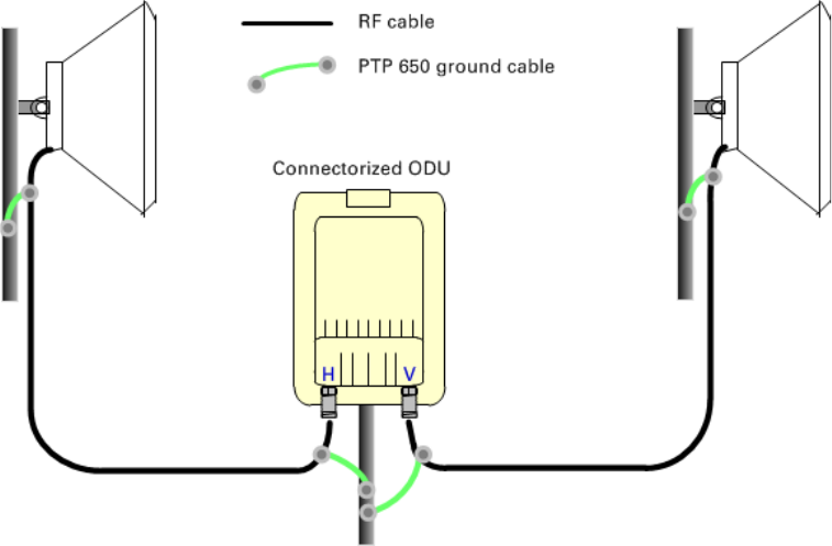
Chapter 5: Installation Install external antennas for a connectorized ODU
7
Ground the
antenna cables to the supporting structure within 0.3 meters (1 foot) of the ODU and
antennas using the Cambium grounding kit (part number 01010419001):
8
Fix the antenna cables to the supporting structure using site approved methods. Ensure
that no
undue strain is placed on the ODU or antenna connectors. Ensure that the cables do not flap in
the wind, as flapping cables are prone to damage and induce unwanted vibrations in the
supporting structure.
UNDER DEVELOPMENT
Page 5-17
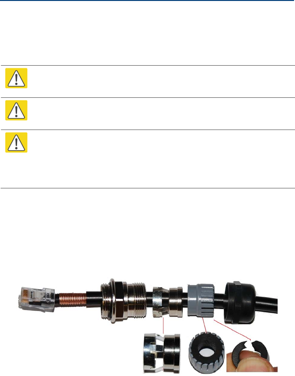
Chapter 5: Installation Installing the copper Cat5e Ethernet interface
Installing the copper Cat5e Ethernet interface
To install the copper Cat5e Ethernet interface, use the following procedures:
• Install the ODU to top LPU drop cable on page 5-18
• Install the main drop cable on page 5-20
• Install the bottom LPU to PSU drop cable on page 5-23
• Test resistance in the drop cable on page 5-25
Caution
To avoid damage to the installation, do not connect or disconnect the drop cable when
power is applied to the PSU or network terminating equipment.
Caution
Do not connect the SFP or Aux drop cables to the PSU, as this may damage
equipment.
Caution
Always use Cat5e cable that is gel-filled and shielded with copper-plated steel.
Alternative types of Cat5e cable are not supported by Cambium Networks. Cambium
Networks supply this cable (Cambium part numbers WB3175 and WB3176), RJ45
connectors (Cambium part number WB3177) and a crimp tool (Cambium part number
WB3211). The LPU and grounding kit contains a 600 mm length of this cable.
Install the ODU to top LPU drop cable
Fit glands to the ODU to top LPU drop cable
Fit EMC strain relief cable glands (with black caps) to both ends of the 600 mm length of
pre-terminated cable. These parts are supplied in the LPU and grounding kit.
1
Disassemble the gland and thread each part onto the cable (the rubber bung is split).
Assemble the spring clip and the rubber bung:
UNDER DEVELOPMENT
Page 5-18
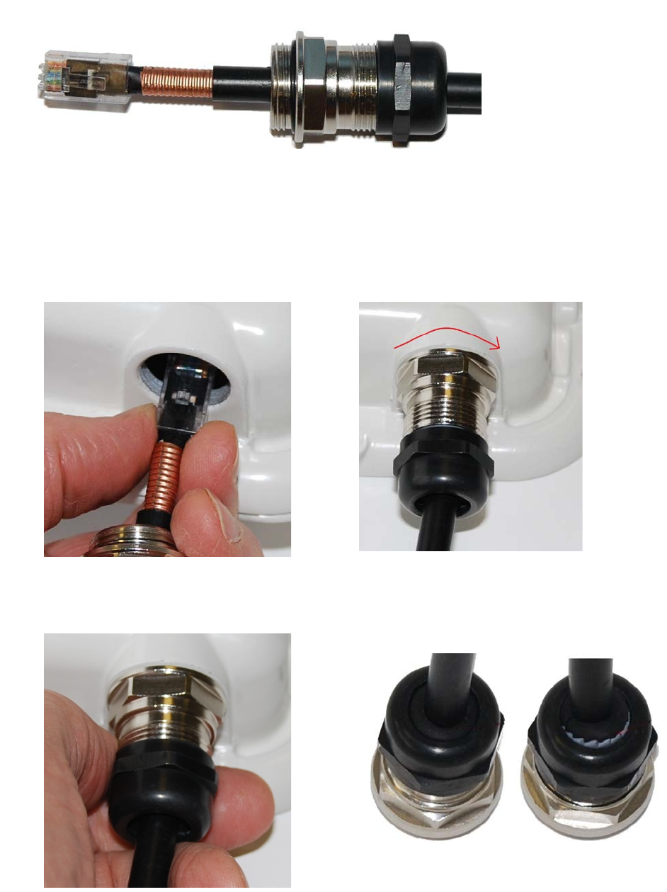
Chapter 5: Installation Installing the copper Cat5e Ethernet interface
2
Fit the parts into the body and lightly screw on the gland nut (do not tighten
it):
Connect the drop cable to the ODU (PSU port) and LPU
1
(a) Plug the RJ45 connector into the socket in the unit, ensuring that it snaps home.
(b) Fit the gland body to the RJ45 port and tighten it to a torque of 5.5 Nm (4.3 lb ft):
(a)
(b)
2
(a) Fit the gland nut and tighten until the rubber seal closes on the cable. (b) Do not over-
tighten the gland nut, as there is a risk of damage to its internal components:
(a)
(b)
Correct
Incorrect
UNDER DEVELOPMENT
Page 5-19
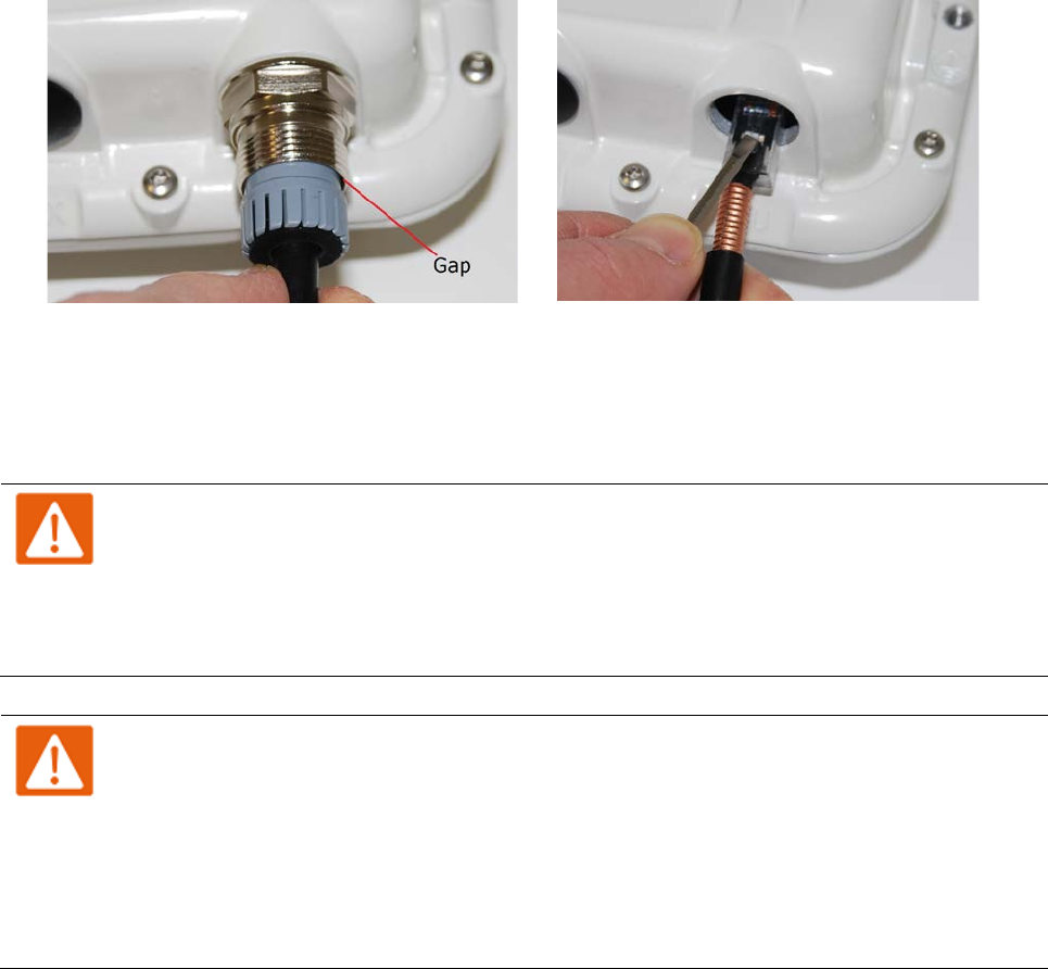
Chapter 5: Installation Installing the copper Cat5e Ethernet interface
Disconnect the drop cable from the LPU or ODU
Use this procedure if it is necessary to remove an EMC strain relief cable gland and RJ45
connector from the ODU (as illustrated) or LPU.
1
(a) Remove the gland nut. Wiggle the drop cable to release the tension of the gland body. When
the tension in the gland body is released, a gap opens at the point show. Unscrew the gland
body.
(b) Use a small screwdriver to press the RJ45 locking tab, the
n remove the RJ45 connector.
(a)
(b)
Install the main drop cable
Warning
The metal screen of the drop cable is very sharp and may cause personal injury.
• ALWAYS wear cut-resistant gloves (check the label to ensure they are cut resistant).
• ALWAYS wear protective eyewear.
• ALWAYS use a rotary blade tool to strip the cable (DO NOT use a bladed knife).
Warning
Failure to obey the following precautions may result in injury or death:
• Use the proper hoisting grip for the cable being installed. If the wrong hoisting grip is
used, slippage or insufficient gripping strength will result.
• Do not reuse hoisting grips. Used grips may have lost elasticity, stretched, or become
weakened. Reusing a grip can cause the cable to slip, break, or fall.
• The minimum requirement is one hoisting grip for each 60 m (200 ft) of cable.
UNDER DEVELOPMENT
Page 5-20
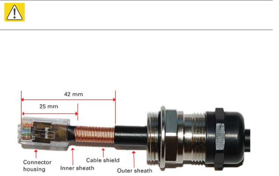
Chapter 5: Installation Installing the copper Cat5e Ethernet interface
Cut to length and fit hoisting grips
1
Cut the main drop cable to length from the top LPU to the bottom LPU.
2
Slide one or more hoisting grips onto the top end of the drop cable.
3
Secure
the hoisting grip to the cable using a special tool, as recommended by the manufacturer.
Terminate with RJ45 connectors and glands
Caution
Check that the crimp tool matches the RJ45 connector, otherwise the cable or
connector may be damaged.
1
Thread the cable gland (with black cap) onto the main drop cable.
2
Strip the cable outer sheath and fit the RJ45 connector load bar.
3
Fit
the RJ45 connector housing as shown. To ensure there is effective strain relief, locate the
cable inner sheath under the connector housing tang
. Do not tighten the gland nut:
UNDER DEVELOPMENT
Page 5-21

Chapter 5: Installation Installing the copper Cat5e Ethernet interface
Hoist and fix the main drop cable
Warning
Failure to obey the following precautions may result in injury or death:
• Use the hoisting grip to hoist one cable only. Attempting to hoist more than one
cable may cause the hoisting grip to break or the cables to fall.
• Do not use the hoisting grip for lowering cable unless the clamp is securely in place.
• Maintain tension on the hoisting grip during hoisting. Loss of tension can cause
dangerous movement of the cable and result in injury or death to personnel.
• Do not release tension on the grip until after the grip handle has been fastened to the
supporting structure.
• Do not apply any strain to the RJ45 connectors.
Caution
Do not lay the drop cable alongside a lightning air terminal.
1
Hoist the top end of the main drop cable up to the top LPU, following the hoist manufacturer’s
instructions. When the cable is in position, fasten the grip handle to
the supporting structure
and remove the hoist line.
2
Connect th
e main drop cable to the top LPU by following the procedure Connect the drop cable
to the ODU (PSU port) and LPU
on page 5-19.
3
R
un the main drop cable to the site of the bottom LPU.
4
Attach the main drop cable to the supporting structure
using site approved methods.
Ground the main drop cable
At all required grounding points, connect the screen of the main drop cable to the metal of the
supporting structure using the cable grounding kit (Cambium part number 01010419001).
UNDER DEVELOPMENT
Page 5-22
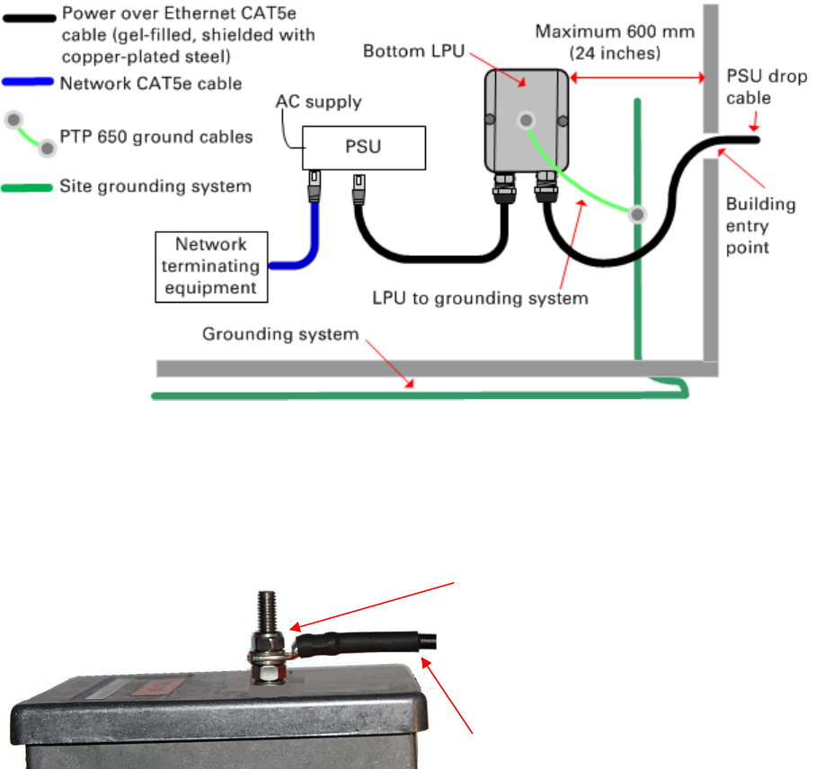
Chapter 5: Installation Installing the copper Cat5e Ethernet interface
Install the bottom LPU to PSU drop cable
Install the bottom LPU
Install the bottom LPU, ground it, and connect it to the main drop cable.
1
Select a mounting point for the bottom LPU within 600 mm (24 in) of the building entry point.
Mount the LPU vertically with cable glands facing downwards.
2
Connect the main drop cable to the bottom LPU by following the procedure Connect the drop cable
to the ODU (PSU port) and LPU on page 5-19.
3
Fasten one ground cable to the bottom LPU using the M6 (small) lug. Tighten both nuts to a
torque of 5 Nm (3.9 lb ft):
Locking nut
Washer
M6 lug
Washer
Nut
Toothed washer
M10 lug to ground
4
Select a building grounding point near the LPU bracket. Remove paint from the surface and
apply anti-oxidant compound. Fasten the LPU ground cable using the M10 (large) lug.
UNDER DEVELOPMENT
Page 5-23
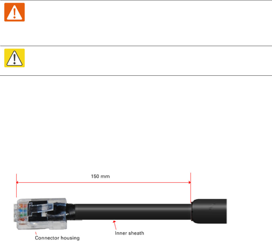
Chapter 5: Installation Installing the copper Cat5e Ethernet interface
Install the LPU to PSU drop cable
Use this procedure to terminate the bottom LPU to PSU drop cable with RJ45 connectors at both
ends, and with a cable gland at the LPU end.
Warning
The metal screen of the drop cable is very sharp and may cause personal injury.
ALWAYS wear cut-resistant gloves (check the label to ensure they are cut resistant).
ALWAYS wear protective eyewear. ALWAYS use a rotary blade tool to strip the cable,
not a bladed knife.
Caution
Check that the crimp tool matches the RJ45 connector, otherwise the cable or
connector may be damaged.
1
Cut the drop cable to the length required from bottom LPU to PSU.
2
At the LPU end only
:
• Fit one cable gland and one RJ45 connector by following the procedure Terminate with
RJ45 connectors and glands on page 5-21.
• Connect this cable and gland to the bottom LPU by following the procedure Connect the
drop cable to the ODU (PSU port) and LPU on page 5-19.
4
At the PSU end only
: Do not fit a cable gland. Strip the cable outer sheath and fit the RJ45
connector load bar. Fit the RJ45 connector housing. To ensure there is effective strain relief,
locate the cable inner sheath under the connector housing tang:
UNDER DEVELOPMENT
Page 5-24

Chapter 5: Installation Installing the copper Cat5e Ethernet interface
Test resistance in the drop cable
Connect the bottom end of the copper Cat5e drop cable to a PTP drop cable tester and test that the
resistances between pins are within the correct limits, as specified in the table below. If any of the
tests fail, examine the drop cable for wiring faults. Order the PTP drop cable tester from the
support website (http://www.cambiumnetworks.com/support).
Measure the
resistance
between…
Enter
measured
resistance
To pass test,
resistance must
be…
Circle
“Pass” or
“Fail”
Additional tests and
notes
Pins 1 and 2 Ohms <20 Ohms
(60 Ohms) (*1)
Pass
Fail Resistances must be
within 10% of each other
(*2). Circle “Pass” or
“Fail”:
Pass
Fail
Pins 3 and 6 Ohms <20 Ohms
(60 Ohms) (*1)
Pass
Fail
Pins 4 and 5 Ohms <20 Ohms
(60 Ohms) (*1)
Pass
Fail
Pins 7 and 8 Ohms <20 Ohms
(60 Ohms) (*1)
Pass
Fail
Pin 1 and screen
(ODU ground)
K Ohms >100K Ohms Pass
Fail These limits apply
regardless of cable
length.
Pin 8 and screen
(ODU ground)
K Ohms >100K Ohms Pass
Fail
(*1) A resistance of 20 Ohms is the maximum allowed when the cable is carrying Ethernet.
A resistance of 60 Ohms is the maximum allowed when the cable is carrying only power to the
ODU (when Ethernet is carried by one of the other ODU interfaces).
(*2) Ensure that these resistances are within 10% of each other by multiplying the lowest
resistance by 1.1 – if any of the other resistances are greater than this, the test has failed.
UNDER DEVELOPMENT
Page 5-25
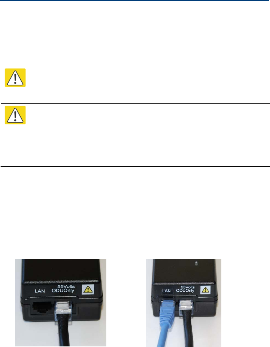
Chapter 5: Installation Installing the PSU
Installing the PSU
Install one of the following types of PSU (as specified in the installation plan):
• PTP 650 AC Power Injector (Cambium part number N000065L001). Refer to Installing the AC
Power Injector on page 5-26.
• PTP 650 AC+DC Enhanced Power Injector (Cambium part number C000065L002). Refer to
Installing the AC+DC Enhanced Power Injector on page 5-27.
Caution
As the PSU is not waterproof, locate it away from sources of moisture, either in the
equipment building or in a ventilated moisture-proof enclosure. Do not locate the
PSU in a position where it may exceed its temperature rating.
Caution
Do not plug any device other than a PTP 650 ODU into the ODU port of the PSU. Other
devices may be damaged due to the non-standard techniques employed to inject DC
power into the Ethernet connection between the PSU and the ODU.
Do not plug any device other than a Cambium PTP 650 PSU into the PSU port of the
ODU. Plugging any other device into the PSU port of the ODU may damage the ODU
and device.
Installing the AC Power Injector
Follow this procedure to install the AC Power Injector (Cambium part number N000065L001):
1
Form a drip loop on the PSU end of the LPU to PSU drop cable. The drip loop ensures that
any moisture that runs down the cable cannot enter the PSU.
2
(a) Place the AC Power Injector on a horizontal surface. Plug the LPU to PSU drop cable into
the PSU port labeled ODU. (b) When the system is ready for network connection, connect the
network Cat5e cable to the LAN port of the PSU:
(a)
(b)
UNDER DEVELOPMENT
Page 5-26

Chapter 5: Installation Installing the PSU
Installing the AC+DC Enhanced Power Injector
Follow this procedure to install the AC+DC Enhanced Power Injector (Cambium part number
C000065L002):
1
Mount the AC+DC power injector by screwing it to a vertical or horizontal surface using the
four screw holes (circled):
2
Form a drip loop on the PSU end of the LPU to PSU drop cable. The drip loop ensures that
any moisture that runs down the cable into the cabinet or enclosure cannot enter the PSU.
3
(a) Undo the retaining screw, hinge back the cover and plug the drop cable or the cable from
the PTP-SYNC into the port. (b) Close the cover and secure with the screw. (c) When the
system is ready for network connection, connect the network Cat5e cable to the LAN port of
the PSU:
(a)
(b) and (c)
UNDER DEVELOPMENT
Page 5-27
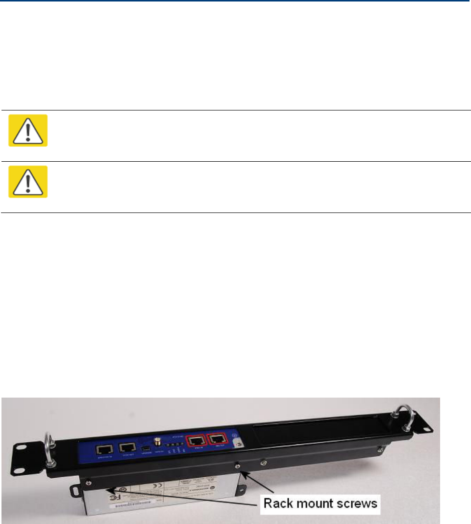
Chapter 5: Installation Installing a PTP-SYNC unit
Installing a PTP-SYNC unit
To install a PTP-SYNC unit (for TDD synchronization), use the following procedures:
• Mounting the PTP-SYNC unit on page 5-28
• Connecting up the PTP-SYNC unit on page 5-29
• Powering up the PTP-SYNC installation on page 5-31
Caution
The PTP-SYNC unit must be installed indoors in a non-condensing environment,
otherwise it will be prone to water damage.
Caution
To protect the PTP-SYNC from damage, disconnect the power supply from the PSU
before connecting up the PTP-SYNC.
Mounting the PTP-SYNC unit
Use this procedure to install the PTP-SYNC unit in the equipment building, either in a rack or on a
wall.
• Racking mounting option: fix the PTP-SYNC to the rack mount using the M3 screws from the
rack mount installation kit (Figure 96).
• Wall mounting option: mount the PTP-SYNC vertically with interfaces and cabling facing
downwards (Figure 97).
Figure 96
PTP-SYNC mounted in a rack
UNDER DEVELOPMENT
Page 5-28
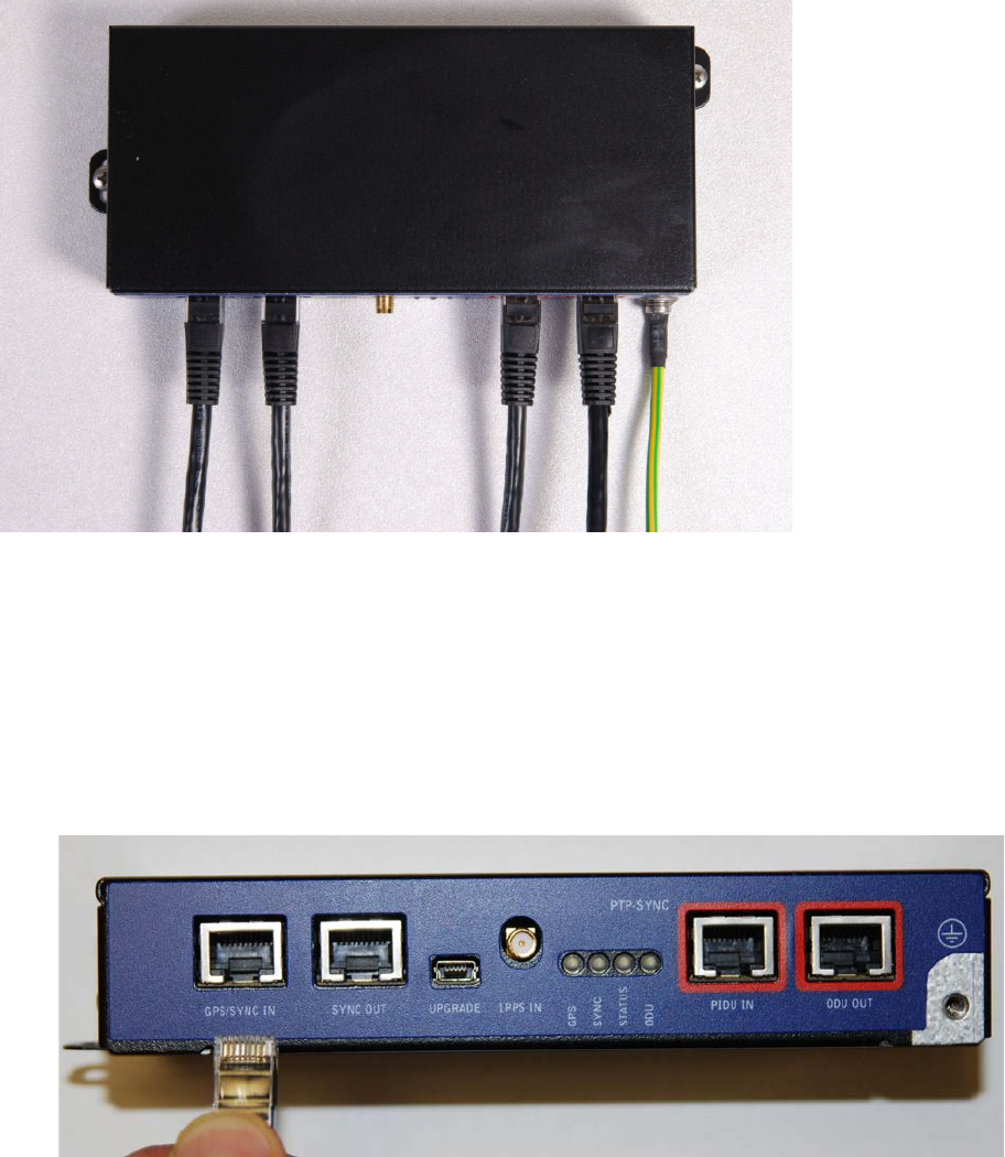
Chapter 5: Installation Installing a PTP-SYNC unit
Figure 97
PTP-SYNC mounted on a wall
Connecting up the PTP-SYNC unit
Use this procedure to connect the PTP-SYNC to the AC+DC Power Injector, ODU, GPS receiver (if
fitted), and LPU (if fitted).
1
Disconnect the power supply from the AC+DC Power Injector.
2
If using GPS, connect the cable from the GPS unit to the GPS/SYNC IN port.
UNDER DEVELOPMENT
Page 5-29
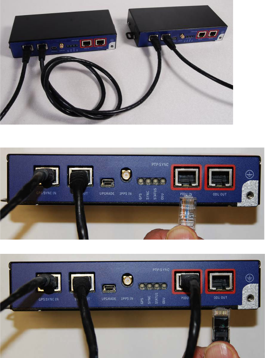
Chapter 5: Installation Installing a PTP-SYNC unit
3
To link clustered PTP-SYNC units, connect the SYNC OUT port of the first PTP-SYNC to the
GPS/SYNC IN port of the second PTP-SYNC in the chain. Repeat for subsequent PTP-SYNC units
in the chain.
4
Connect the cable from the PSU to the PIDU IN port. A suitable 1 meter cable is included in the
PTP-SYNC kit.
5
Connect the cable from the ODU to the ODU OUT port.
UNDER DEVELOPMENT
Page 5-30
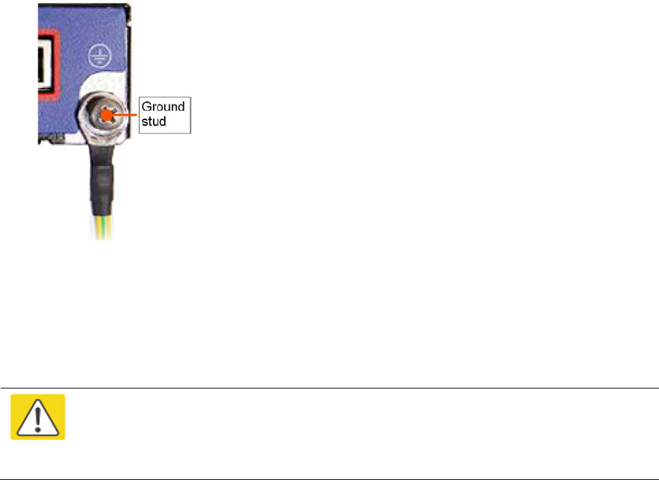
Chapter 5: Installation Installing a PTP-SYNC unit
6
Use a grounding cable to connect the ground stud of the PTP-SYNC to the master ground bar of
the building, or to the rack ground bar.
Powering up the PTP-SYNC installation
Use this procedure to power up the PTP-SYNC installation.
Caution
Ensure that all cables are connected to the correct interfaces of the PTP SYNC unit
and the GPS receiver (if used). Ensure that the installation is correctly grounded
Failure to do so may result in damage to the equipment.
1
Connect the power supply to the PSU.
2
Within 90 seconds, the PTP-SYNC STATUS LED should blink once every second to show that
satellite lock has been achieved.
3
If the system does not operate correctly, refer to Testing PTP-SYNC on page 8-10.
UNDER DEVELOPMENT
Page 5-31

Chapter 5: Installation Installing a GPS receiver
Installing a GPS receiver
To install a GPS receiver as the timing reference source for PTP-SYNC, use the following
procedures:
• Mounting the GPS receiver on page 5-32
• Preparing the GPS drop cable on page 5-32
• Assembling an RJ45 plug and housing for GPS on page 5-33
• Assembling a 12 way circular connector on page 5-35
• Connecting the GPS drop cable on page 5-39
• Top grounding point for GPS adapter cable on page 5-40
• Installing and connecting the GPS LPU on page 5-41
Caution
Prior to power-up of equipment, ensure that all cables are connected to the correct
interfaces of the PTP-SYNC unit and the GPS receiver module. Failure to do so may
result in damage to the equipment.
Mounting the GPS receiver
Mount the GPS receiver (following manufacturer’s instructions) upon either an external wall
(Figure 41) or a metal tower or mast (Figure 42).
Preparing the GPS drop cable
Use this procedure to make the main drop cable that will connect the GPS receiver to its bottom
LPU. GPS drop cables do not require top LPUs.
Caution
Always use Cat5e cable that is gel-filled and shielded with copper-plated steel.
Alternative types of cable are not supported by Cambium.
1
Measure the distance from the GPS receiver to the LPU site at building entry.
2
Cut the required length of drop cable.
3
Attach one or more hoisting grips to the top end of the cable, as described in Install the main drop
cable on page 5-20.
UNDER DEVELOPMENT
Page 5-32
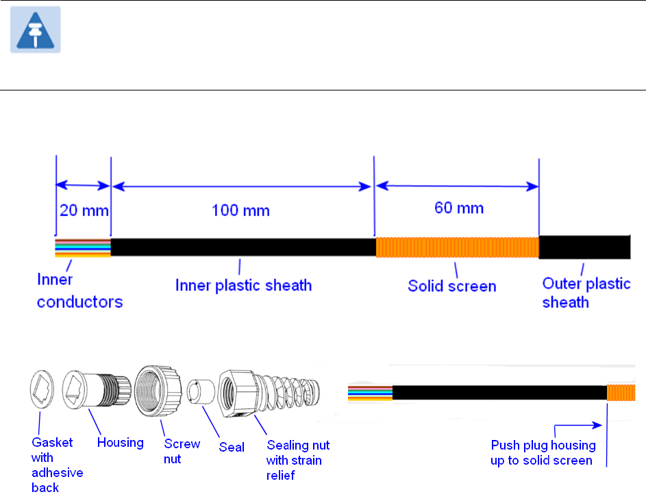
Chapter 5: Installation Installing a GPS receiver
4
Fit a suitable GPS connector to the top end of the drop cable:
• If a GPS adapter cable kit is available, attach the plug housing and an RJ45 plug to the top end
of the main GPS drop cable, as described in Assembling an RJ45 plug and housing for GPS on
page 5-33.
• If a GPS adapter cable kit is not available, fit a 12 way circular connector to the top end of the
main drop cable as described in Assembling a 12 way circular connector on page 5-35.
5
Hoist the GPS drop cable safely up a tower or building, as described in Install the main drop cable
.
on page 5-20.
Assembling an RJ45 plug and housing for GPS
Use this procedure to assemble the plug housing over the end of the drop cable. This procedure is
only performed when a GPS adapter cable kit is available. This kit is used to connect the Trimble
Acutime™ GG GPS receiver or the Trimble Acutime™ Gold GPS receiver to the GPS drop cable.
The kit contains an adapter cable (GPS receiver circular connector to RJ45 socket) and an RJ45
plug housing. The plug housing should be assembled over the end of the drop cable to provide a
sealed connection to the adapter cable.
Note
These instructions are for the preparation of the Cambium-supplied drop cable type
(Superior Essex BBDGE). Other types of cable may need different preparation
methods.
1
Prepare the top end of the GPS drop cable.
2
Install plug housing from the converter kit onto the prepared cable. Do not tighten the nuts at
this stage.
UNDER DEVELOPMENT
Page 5-33
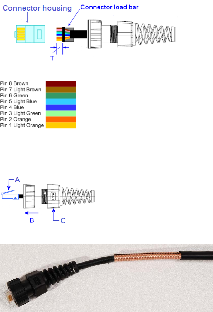
Chapter 5: Installation Installing a GPS receiver
3
Install the RJ45 crimp plug.
Start with tails over-length to assist insertion into load bar, then trim them to 5 mm (T).
Connect the RJ45 pins to the following conductors (Superior Essex BBDGe colors):
4
Assemble plug housing:
Depress the RJ45 locking tab (A).
Slide the plug housing assembly (B) over the RJ45 plug.
Tighten the sealing nut (C). This is easier to fully tighten when the plug housing is mated
to the socket of the adapter cable.
5
Check the assembly. This is an exampled of an assembled plug housing on the end of a drop
cable:
UNDER DEVELOPMENT
Page 5-34

Chapter 5: Installation Installing a GPS receiver
Assembling a 12 way circular connector
Use this procedure to connect the GPS drop cable to a 12 way circular connector. This procedure is
only performed when a GPS adapter cable kit is NOT available.
Note
This procedure requires a soldering iron and solder
.
Caution
The drop cable has solid copper conductors. There are a limited number of times
each conductor can be bent before it fatigues and fails.
Table 114 shows how the 12 way circular connector locations map to the PTP-SYNC RJ45 pins.
Figure 98 illustrates this mapping.
Table 114
GPS 12 way circular connector to RJ45 pin mappings
GPS
connector
location
Function
Cat5e wire color
PTP-SYNC
(J10)
RJ45 pin
PTP-SYNC
signal
name
Conventional
Supported
drop cable
1 DC Pwr (12V) Orange/White Light Orange 1 12VGPS
2 RxB- Brown/White Light Brown 7 GPS_TXDA
3 RxB+ Brown Brown 8 GPS_TXDB
4 TxB- Blue Blue 4 GPS_RXDA
5 TxB+ Blue/White Light Blue 5 GPS_RXDB
6 RxA- N.C N.C ---
7 RxA+ N.C N.C ---
8 TxA- N.C N.C ---
9 DC Ground Orange Orange 2 GND
10 TxA+ N.C N.C ---
11 Tx1PPS+ Green/White Light Green 3 GPS_1PPSA
12 Tx1PPS- Green Green 6 GPS_1PPSB
UNDER DEVELOPMENT
Page 5-35
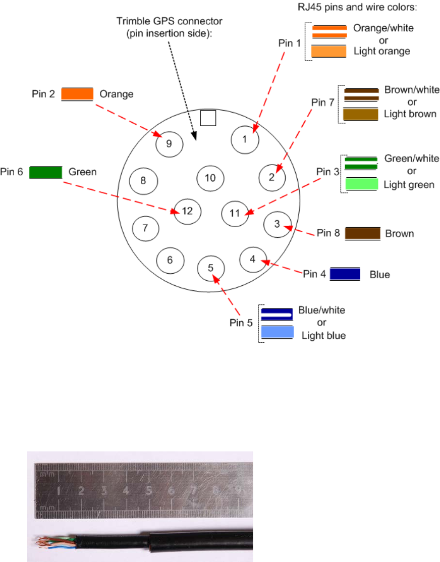
Chapter 5: Installation Installing a GPS receiver
Figure 98
Inserting RJ45 pins into the 12 way circular connector
1
Prepare the drop cable end as follows:
• Bare back the cable outer and copper screen to 50mm.
• Bare back the cable inner to 17mm.
• Un-twist the cable pairs.
• Strip the individual conductors to 5mm.
UNDER DEVELOPMENT
Page 5-36
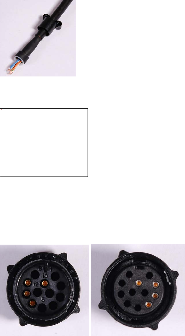
Chapter 5: Installation Installing a GPS receiver
2
Fit the plug outer, associated boot, and boot insert.
3
Connect the socket contacts using either of the following techniques:
•
Crimp
: Crimp the socket contacts onto each of the conductors using the correct crimp tool and
positioner, setting the wire size selector to “3” for 24AWG wire.
•
Solder
: When soldering the socket contacts onto each of the conductors, ensure that there is
no solder or flux residue on the outside of the contact. Care should also be taken that the
individual conductor insulation does not peel back with the soldering heat, allowing possible
shorts when assembled into the plug shell.
4
Fit four dummy contacts into the unused 12 way circular connector locations (6, 7, 8 and 10), to
provide strength and sealing. Push the contacts in from the pin insertion side.
Pin insertion side: Plug mating side:
This image cannot currently be displayed.
UNDER DEVELOPMENT
Page 5-37
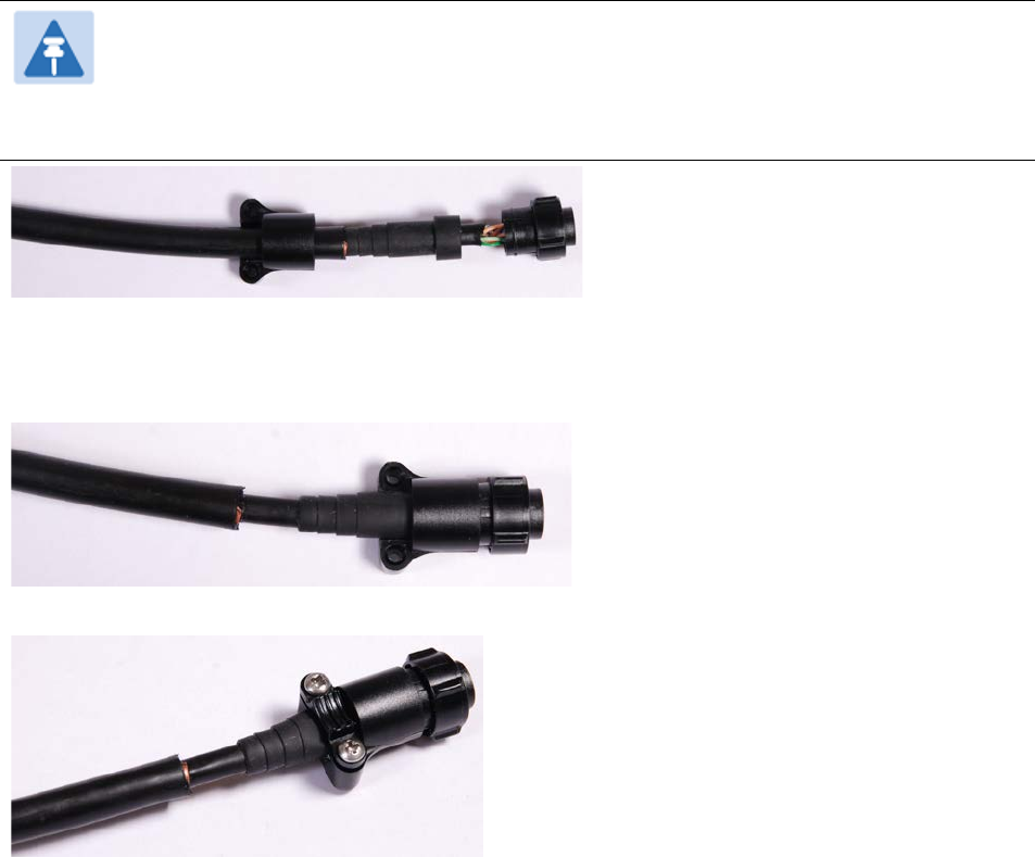
Chapter 5: Installation Installing a GPS receiver
5
Insert the eight RJ45 contact pins into the pin insertion side of the 12 way circular connector in
accordance with Figure 98.
It is easiest to insert the pins from the center out, in descending order of Trimble location number,
that is, 12, 11, 9, 5, 4, 3, 2, 1. Push the contacts in so that the shoulder on the contact fits into the
hole in the plug shell. When all contacts have been fitted, push them in further to engage with the
locking mechanism in the plug shell. This can be done by applying pressure to the contact with a
small diameter stiff object, such as tweezers.
Note
If a contact is pushed in to the point where the locking mechanism engages before all
of the contacts have been inserted it will limit the amount of room available to fit the
remaining contacts, requiring harder bends to be applied.
6
Fit the plug to its shell. The plastic ring fits inside the rubber boot and ensures a tight fit when the
plug body is clipped onto the plug shell. Be aware that the plug body is a hard push fit onto the
plug shell.
7
Fit the strain relief clip.
UNDER DEVELOPMENT
Page 5-38
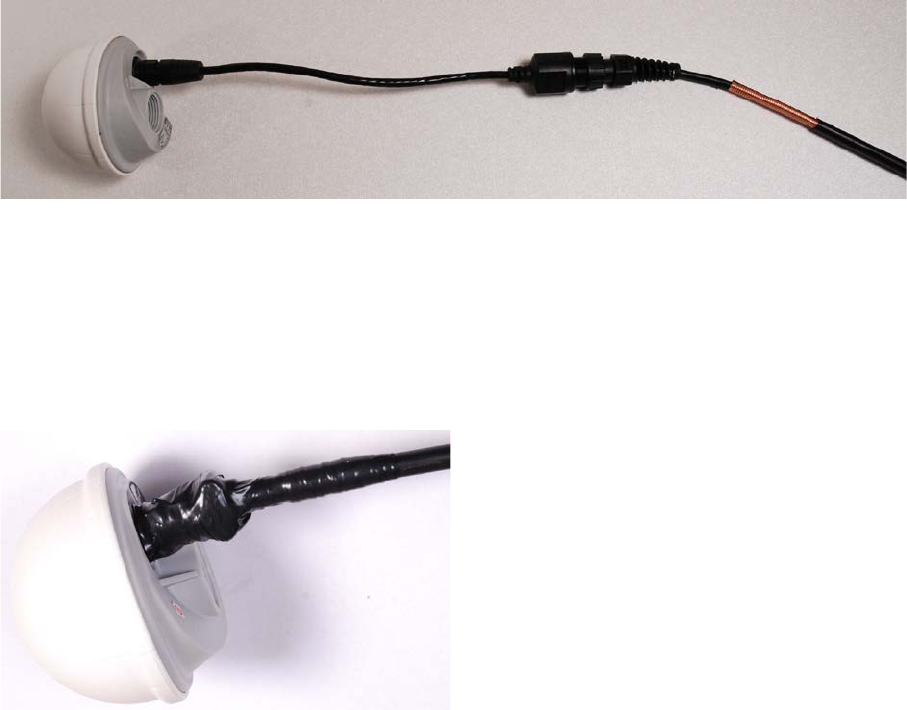
Chapter 5: Installation Installing a GPS receiver
Connecting the GPS drop cable
Use this procedure to connect the GPS drop cable to the GPS unit and supporting structure.
1
If a GPS adapter cable is available, use it to connect the main GPS drop cable to the GPS unit:
2
If a GPS adapter cable is not available, connect the main GPS drop cable to the GPS unit via a 12
way circular connector. Weatherproof the connection as follows:
• Wrap a layer of self-amalgamating tape, starting 25mm below the bared back outer of the
cable and finishing at the GPS housing.
• Wrap a layer of PVC tape, starting just below the start of the self-amalgamating tape and
finishing at the GPS housing, overlapping at half width.
• Repeat with four more layers of PVC tape alternating the start and finish ends.
3
Lay the main drop cable as far as the building entry point, ensuring there is enough length to
extend through the wall of the building to the LPU.
4
Attach the main GPS drop cable to the supporting structure using site approved methods.
5
Ground the GPS drop cable to the supporting structure at the points shown in Figure 41 (wall
installation) or Figure 42 (mast or tower installation):
• For standard grounding instructions, see Creating a drop cable grounding point on page 5-
59.
• If a GPS adapter cable has been installed, see Top grounding point for GPS adapter cable on
page 5-40.
UNDER DEVELOPMENT
Page 5-39
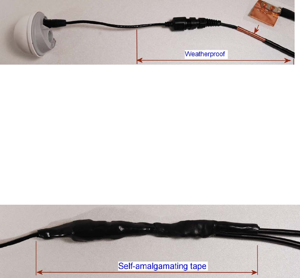
Chapter 5: Installation Installing a GPS receiver
Top grounding point for GPS adapter cable
If a GPS adapter cable has been installed (Figure 99), use this procedure to ground the drop cable
at the point where the solid screen is already exposed, and weatherproof both the ground cable
joint and the RJ45 connection.
Figure 99
Grounding and weatherproofing requirements for GPS adapter cable
Follow the procedure described in Creating a drop cable grounding point on page 5-59, but
observe the following differences:
• There is no need to remove 60mm (2.5inches) of the drop cable outer sheath, as this has
already been done.
• Wrap the top layer of self-amalgamating tape around the complete assembly (not just the
ground cable joint), including the RJ45 connection with the GPS adapter cable (Figure 100).
• Wrap all five layers of PVC tape around the complete assembly (Figure 101). Wrap the layers in
alternate directions: (1st) bottom to top; (2nd) top to bottom; (3rd) bottom to top; (4th) top to
bottom; (5th) bottom to top. The edges of each layer should be 25mm (1 inch) above (A) and
25 mm (1 inch) below (B) the previous layer.
• Check that the joint between the GPS adapter cable, drop cable and ground cable is fully
weatherproofed (Figure 102).
Figure 100
Wrapping self-amalgamating tape around the GPS adapter cable joint
UNDER DEVELOPMENT
Page 5-40
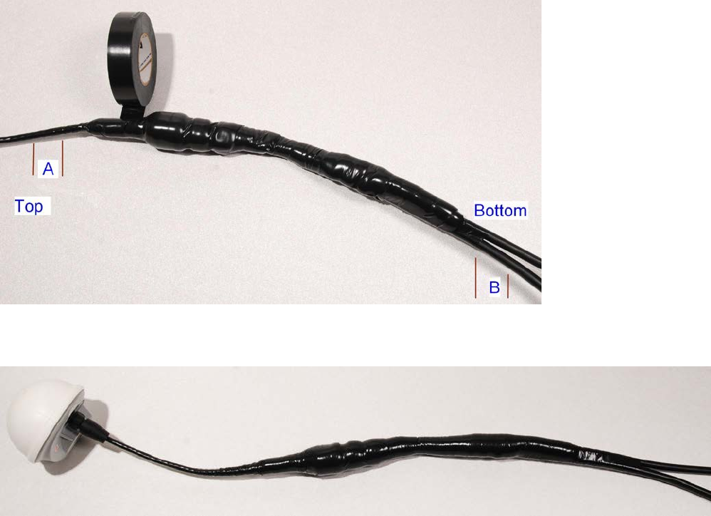
Chapter 5: Installation Installing a GPS receiver
Figure 101
Wrapping PVC tape around the GPS adapter cable joint
Figure 102
Grounding and weatherproofing example for GPS adapter cable
Installing and connecting the GPS LPU
Install and ground the GPS drop cable LPU at the building (or cabinet) entry point, and install the
LPU-PTP-SYNC drop cable, as described in Install the bottom LPU on page 5-23.
Connect this cable to the PTP-SYNC unit as described in Connecting up the PTP-SYNC unit on page
5-29.
UNDER DEVELOPMENT
Page 5-41
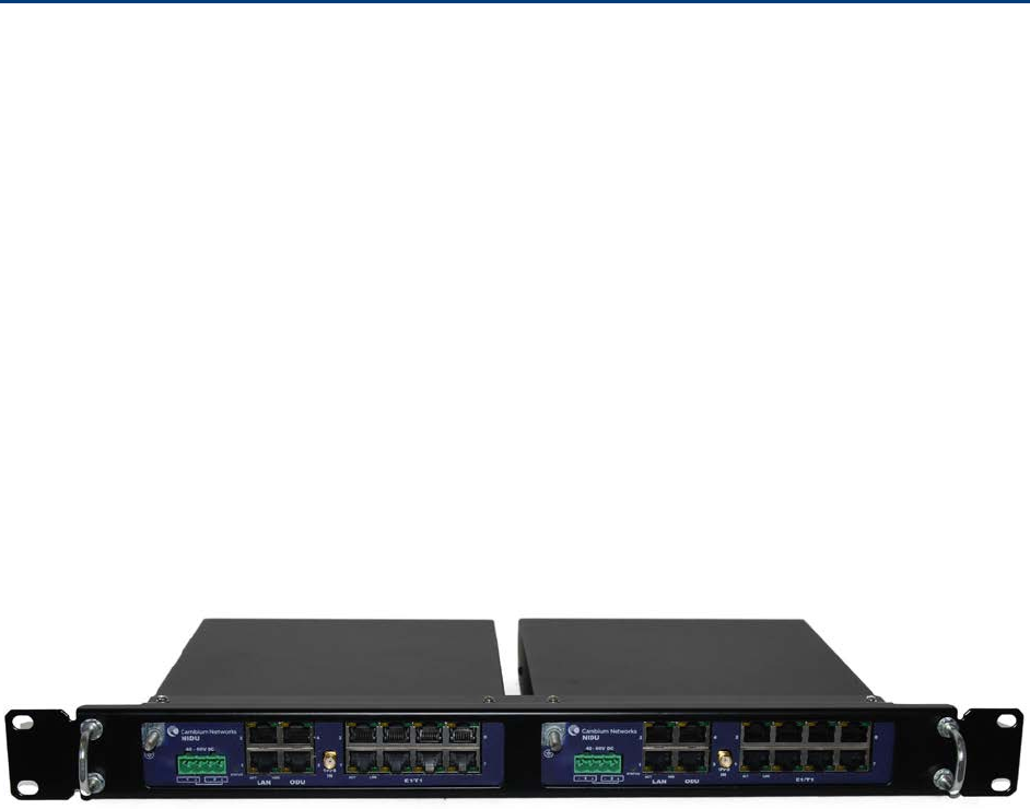
Chapter 5: Installation Installing a NIDU
Installing a NIDU
To install a NIDU (for TDM), use the following procedures:
• Mounting the NIDU on page 5-42
• Connecting the NIDU to the PSU, LAN and TDM cables on page 5-43
• Connecting the NIDU to a DC power supply on page 5-45
Mounting the NIDU
Mount the NIDU in the equipment building, either in a rack or on a horizontal surface:
• Racking mounting option: fix the NIDU to the rack mount using the M3 screws from the rack
mount installation kit (Figure 103). The rack can hold either two NIDUs or one NIDU and one
PTP-SYNC unit.
• Horizontal option: place the NIDU on a horizontal surface.
Figure 103
Two NIDUs mounted in a rack
UNDER DEVELOPMENT
Page 5-42
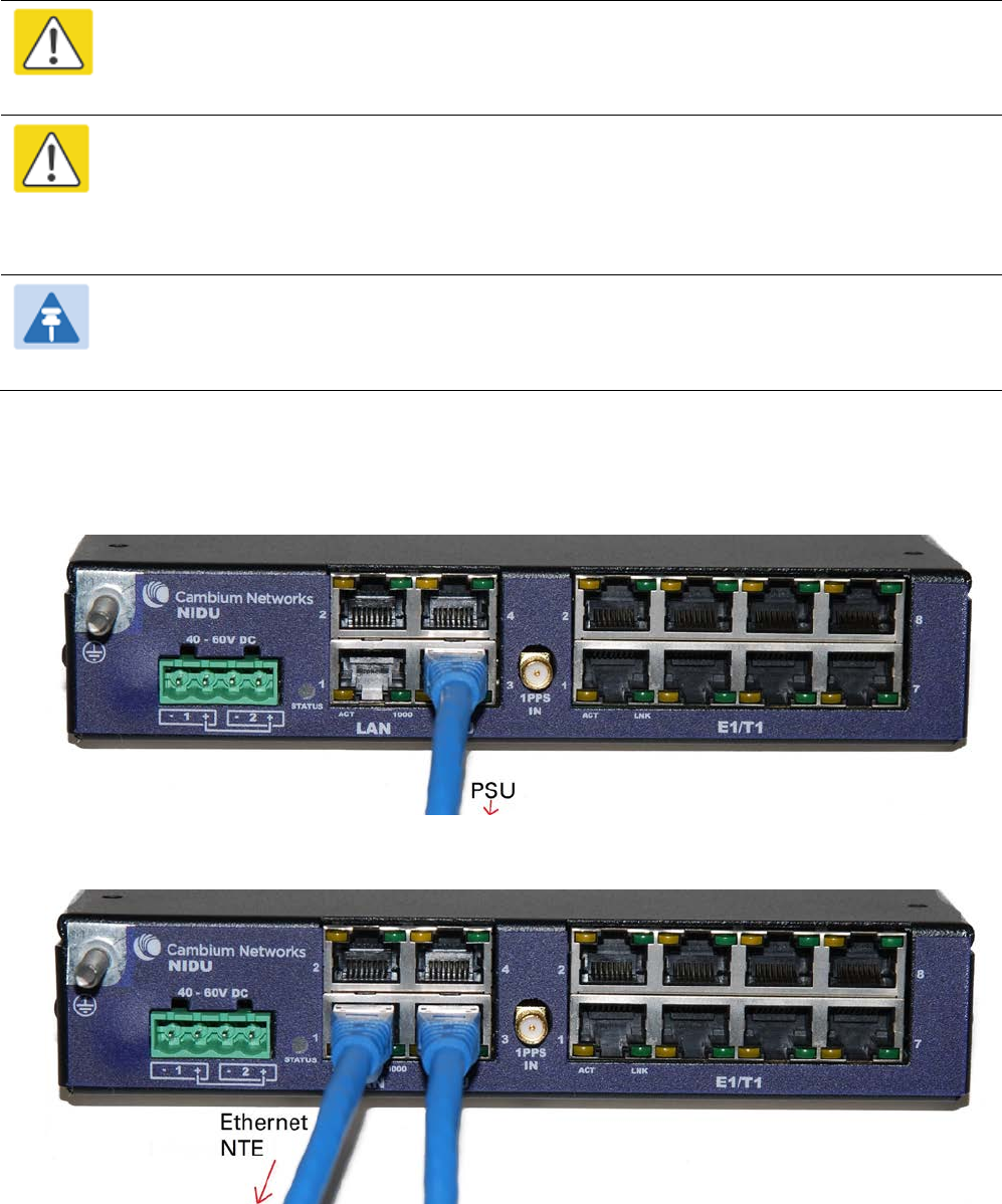
Chapter 5: Installation Installing a NIDU
Connecting the NIDU to the PSU, LAN and TDM cables
Caution
Always connect the NIDU to the Main PSU port of the ODU via the PSU. The TDM service
will not operate if the NIDU is connected to the Aux or SFP port of the ODU.
Caution
If the ODU port has negotiated a link at 100BASE-T, the NIDU will not send or receive TDM
data and will not bridge customer data traffic. Ensure that the Ethernet drop cable between
the ODU and the PSU, and the network cable between the PSU and the NIDU, will reliably
support operation at 1000BASE-T.
Note
Use the E1/T1 ports in ascending numeric sequence, for example: if there is one E1/T1
channel, use port 1; if are three E1/T1 channels, use ports 1, 2 and 3.
Use this procedure to connect the NIDU to the PSU, LAN and TDM transceivers.
1
Disconnect the power supply from the PSU.
2
Connect an indoor Cat5e cable from the NIDU (ODU port 3) to the PSU (LAN port):
3
Connect an indoor Cat5e cable from the NIDU (LAN port 1) to the Ethernet network terminating
equipment:
UNDER DEVELOPMENT
Page 5-43
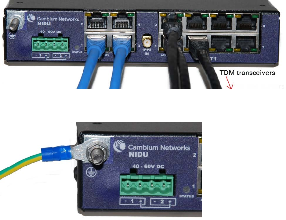
Chapter 5: Installation Installing a NIDU
4
Connect up to eight indoor Cat5e cables (with RJ48 connectors) from the NIDU (E1/T1 ports) to the
local TDM transceivers:
5
Use an M5 nut and washer to connect the grounding cable lug to the NIDU ground bolt. Connect
the other end of the grounding cable to the master ground bar of the building or rack.
UNDER DEVELOPMENT
Page 5-44
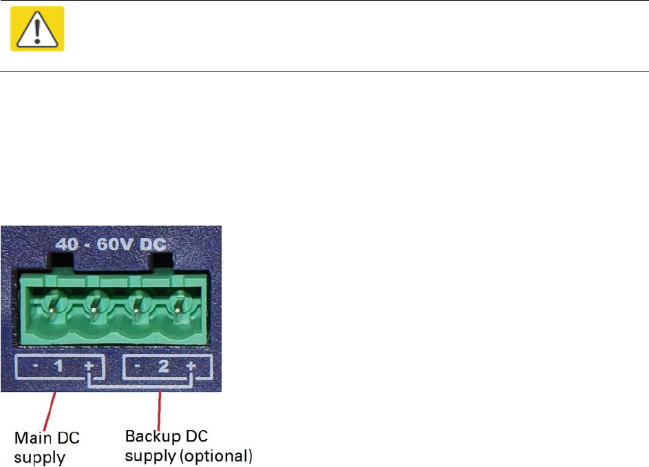
Chapter 5: Installation Installing a NIDU
Connecting the NIDU to a DC power supply
Caution
Do not power up the NIDU until site installation is complete, otherwise equipment
may be damaged.
Main and backup DC supplies
The NIDU requires a 40 V – 60 V DC power supply. The NIDU DC interface provides inputs for a
main and a backup DC power supply (Figure 104). The main DC supply (port 1) is mandatory, but
the backup (port 2) is optional.
Figure 104
NIDU DC interface
Use one of the following power supply options for the NIDU:
• The PTP 650 AC+DC Enhanced Power Injector (Cambium part number C000065L002) with
optional backup.
• An independent DC supply (if available) with optional backup.
• The PTP 800 AC-DC Power Supply Converter (Cambium part number WB3622).
UNDER DEVELOPMENT
Page 5-45
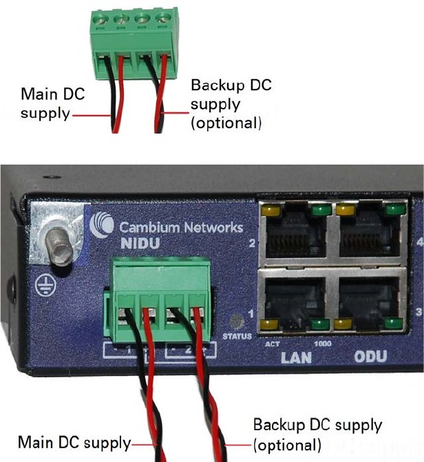
Chapter 5: Installation Installing a NIDU
Using the DC power connector
Use this procedure to connect the NIDU to the PTP 650 AC+DC Enhanced Power Injector (Cambium
part number C000065L002) or to an independent DC supply with an optional backup DC supply:
1
Strip the two wires of the main DC supply cable and screw them into the first and second terminals
of the DC power connector (Cambium part number C000065L044). The first terminal is negative
(black wire) and the second is positive (red wire). If a backup supply is required, use the third and
fourth terminals of the connector:
2
Plug the DC power connector into the NIDU DC interface:
UNDER DEVELOPMENT
Page 5-46
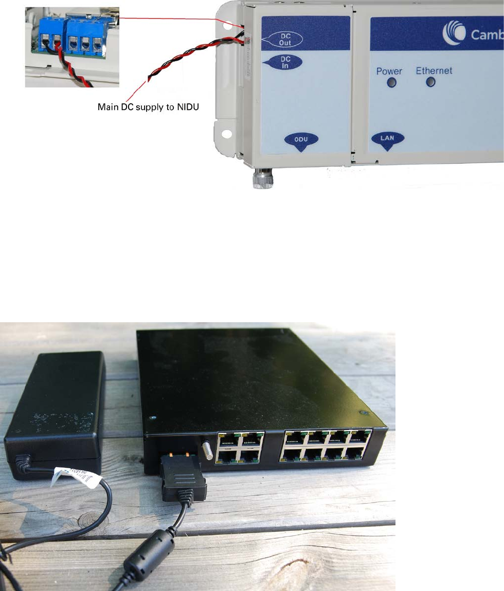
Chapter 5: Installation Installing a NIDU
3
Connect the main DC supply cable to its power source. If this supply is from the AC+DC Enhanced
Power Injector, the DC Out first terminal is negative (black wire) and the second is positive (red
wire):
4
Connect the backup DC supply cable to its power source.
Using the PTP 800 AC-DC Power Supply Converter
If a suitable AC mains supply is available, use the PTP 800 AC-DC Power Supply Converter
(Cambium part number WB3622) to power the NIDU (Figure 105). This includes a DC power
connector that plugs into both ports of the NIDU DC interface.
Figure 105
NIDU powered by the PTP 800 AC-DC Power Supply Converter
UNDER DEVELOPMENT
Page 5-47

Chapter 5: Installation Installing an SFP Ethernet interface
Installing an SFP Ethernet interface
In more advanced configurations, there may be an optical or copper Cat5e Ethernet interface
connected to the SFP port of the ODU. Refer to Typical deployment on page 3-2 for diagrams of
these configurations.
Adapt the installation procedures in this chapter as appropriate for SFP interfaces, noting the
following differences from a PSU interface:
• Install an optical or copper SFP module in the ODU (SFP port) and connect the SFP optical or
copper cable into this module using the long cable gland from the SFP module kit. This is
described in the following procedures:
o Fitting the long cable gland on page 5-50
o Inserting the SFP module on page 5-51
o Connecting the cable on page 5-53
o Fitting the gland on page 5-54
o Removing the cable and SFP module on page 5-56
• Optical cables do not require LPUs or ground cables.
• At the remote end of an SFP drop cable, use an appropriate termination for the connected
device.
• If the connected device is outdoors, not in the equipment building or cabinet, adapt the
grounding instructions as appropriate.
• PTP 650 LPUs are not suitable for installation on SFP copper Cat5e interfaces. For SFP drop
cables, obtain suitable surge protectors from a specialist supplier.
• Ground the top LPUs and surge protector to the same point on the ODU (Figure 106).
UNDER DEVELOPMENT
Page 5-48
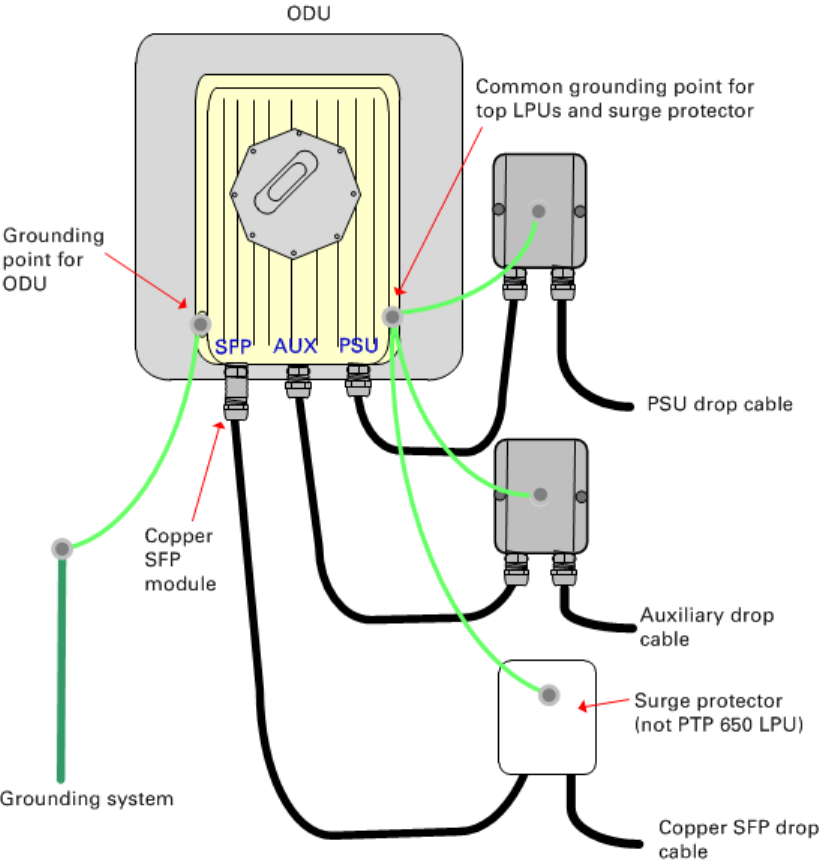
Chapter 5: Installation Installing an SFP Ethernet interface
Figure 106
ODU with copper Cat5e connections to all three Ethernet ports
UNDER DEVELOPMENT
Page 5-49
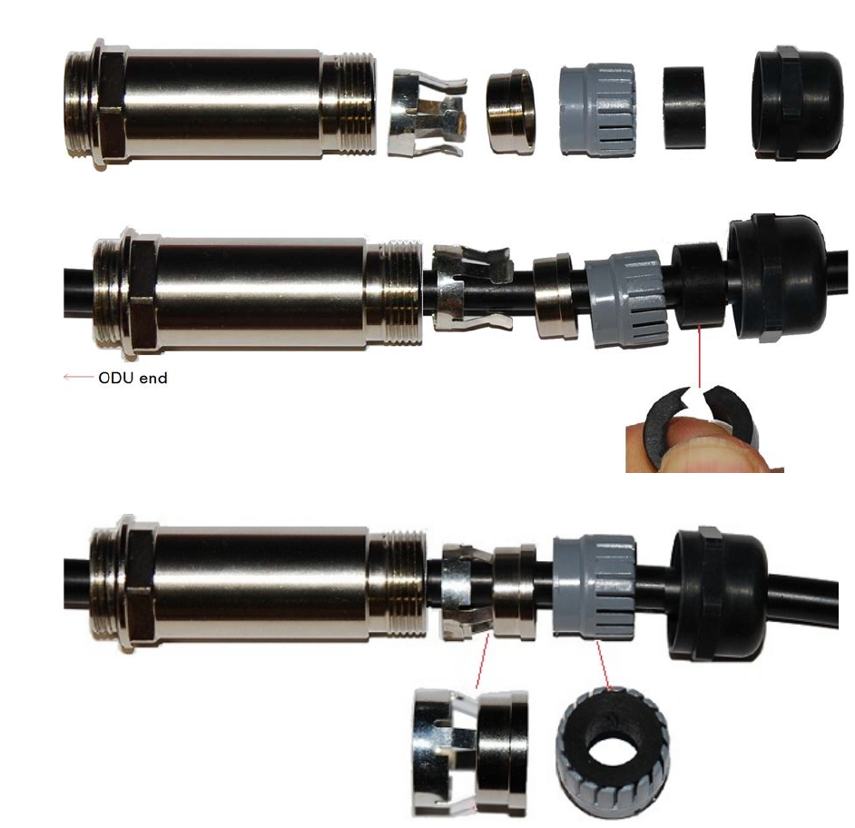
Chapter 5: Installation Installing an SFP Ethernet interface
Fitting the long cable gland
Optical SFP interface
: Disassemble the long cable gland and thread its components over the LC
connector at the ODU end as shown below.
Copper Cat5e SFP interface
: Disassemble the long cable gland and thread its components over the
RJ45 connector at the ODU end as shown below.
1
Disassemble the gland:
2
Thread each part onto the cable (the rubber bung is split):
3
Assemble the spring clip and the rubber bung (the clips go inside the ring):
UNDER DEVELOPMENT
Page 5-50
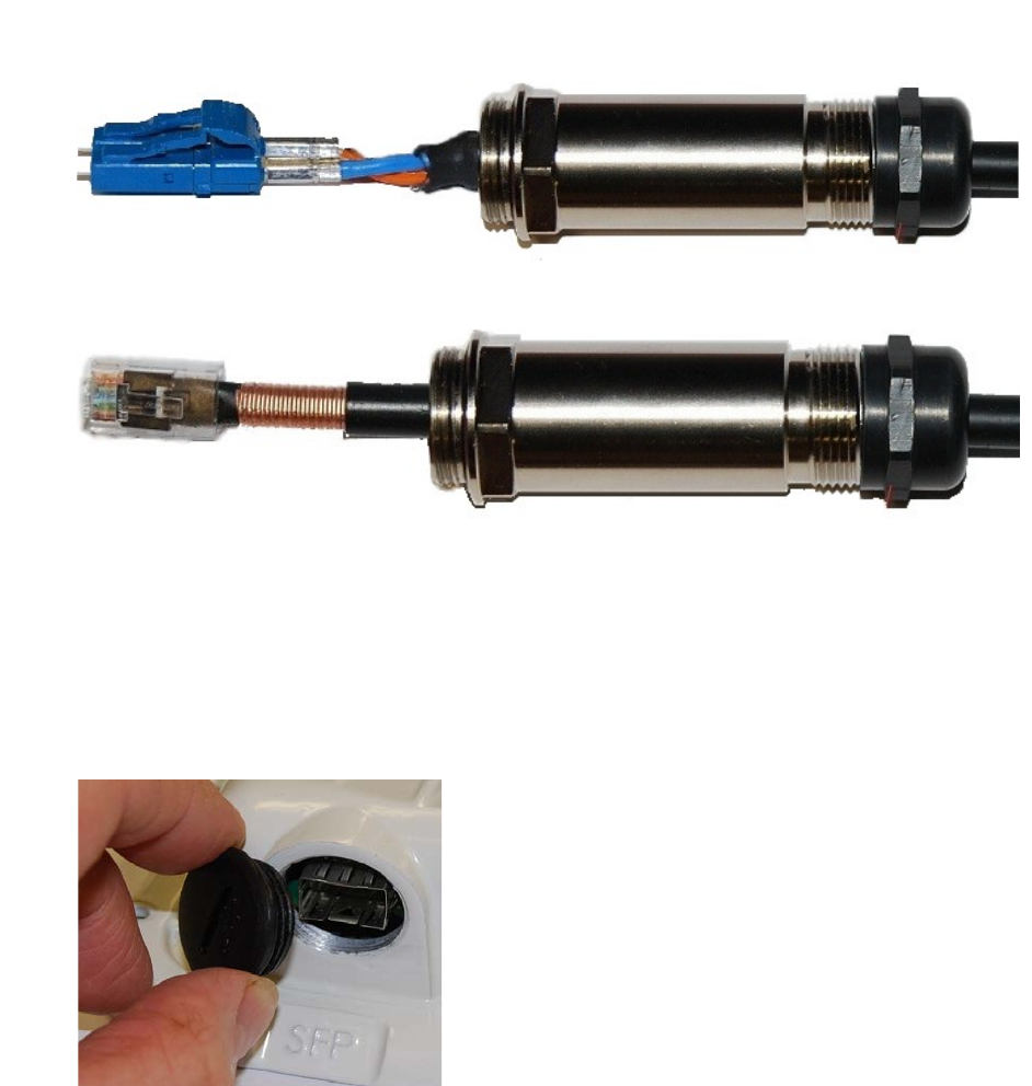
Chapter 5: Installation Installing an SFP Ethernet interface
4
Fit the parts into the body and lightly screw on the gland nut (do not tighten it):
Optical
Copper
Inserting the SFP module
To insert the SFP module into the ODU, proceed as follows:
1
Remove the blanking plug from the SFP port of the ODU:
UNDER DEVELOPMENT
Page 5-51
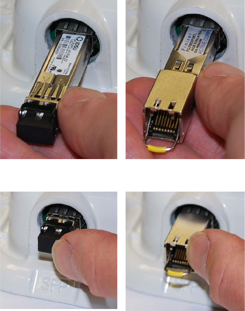
Chapter 5: Installation Installing an SFP Ethernet interface
2
Insert the SFP module into the SFP receptacle
with the label up:
Optical
Copper
3
Push the module home until it clicks into place:
Optical
Copper
UNDER DEVELOPMENT
Page 5-52
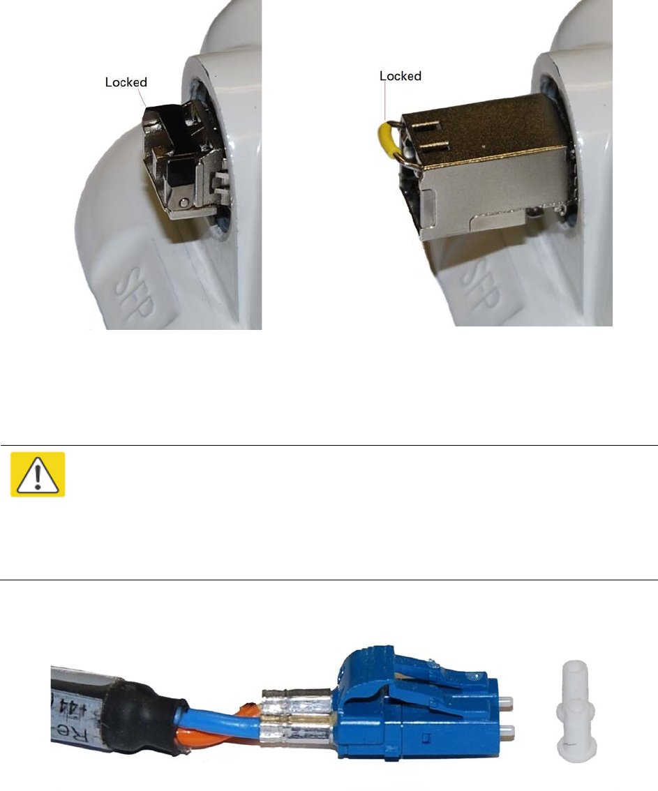
Chapter 5: Installation Installing an SFP Ethernet interface
4
Rotate the latch to the locked position:
Optical
Copper
Connecting the cable
Caution
The fiber optic cable assembly is very delicate. To avoid damage, handle it with
extreme care. Ensure that the fiber optic cable does not twist during assembly,
especially when fitting and tightening the weatherproofing gland.
Do not insert the power over Ethernet drop cable from the PSU into the SFP module,
as this will damage the module.
1
Remove the LC connector dust caps from the ODU end (optical cable only):
2
Plug the connector into the SFP module, ensuring that it snaps home:
UNDER DEVELOPMENT
Page 5-53
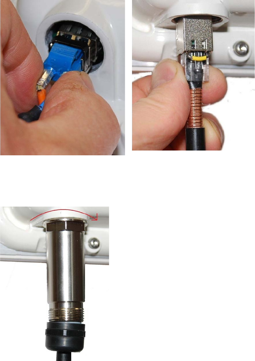
Chapter 5: Installation Installing an SFP Ethernet interface
Optical
Copper
Fitting the gland
1
Fit the gland body to the SFP port and tighten it to a torque of 5.5 Nm (4.3 lb ft)
UNDER DEVELOPMENT
Page 5-54
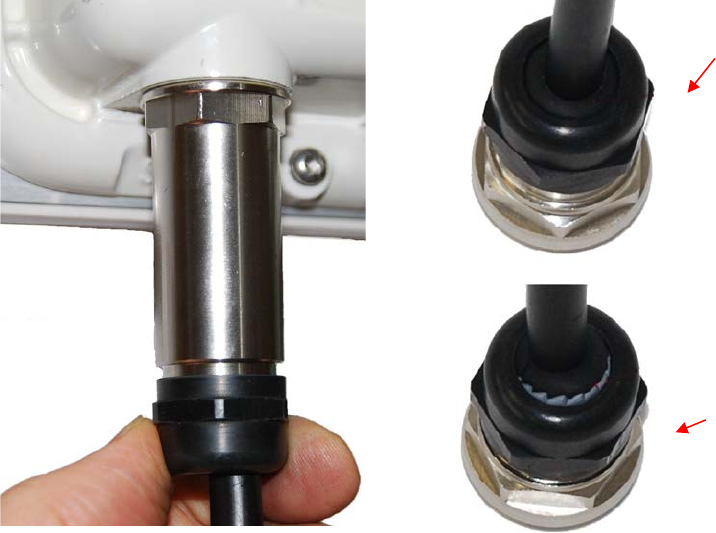
Chapter 5: Installation Installing an SFP Ethernet interface
2
Fit the gland nut and tighten until the rubber seal closes on the cable. Do not over-tighten
the gland nut, as there is a risk of damage to its internal components:
Correct
Incorrect
UNDER DEVELOPMENT
Page 5-55
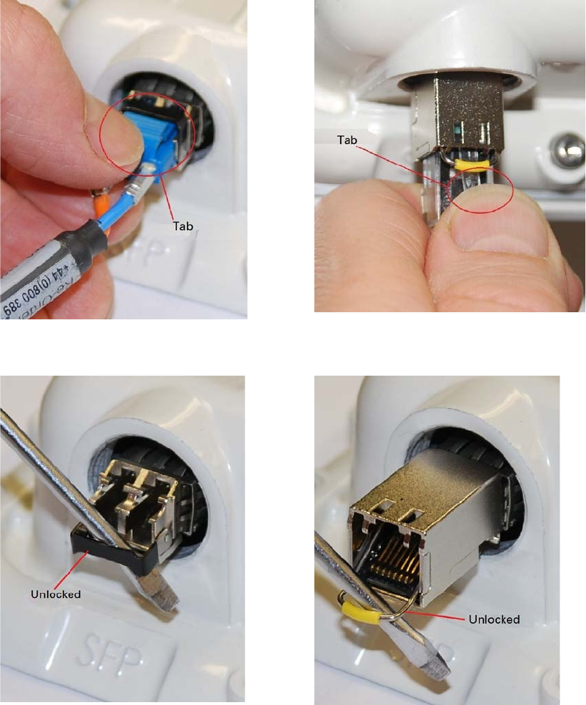
Chapter 5: Installation Installing an SFP Ethernet interface
Removing the cable and SFP module
Do not attempt to remove the module without disconnecting the cable, otherwise the locking
mechanism in the ODU will be damaged.
1
Remove the cable connector by pressing its release tab before pulling it out:
Optical
Copper
2
Rotate the latch to the unlocked position. Extract the module by using a screwdriver:
Optical
Copper
UNDER DEVELOPMENT
Page 5-56

Chapter 5: Installation Installing an Aux Ethernet interface
Installing an Aux Ethernet interface
In more advanced configurations, there may be a copper Cat5e Ethernet interface connected to the
Aux port of the ODU. Refer to Typical deployment on page 3-2 for a diagram of this configuration.
Adapt the installation procedures in this chapter as appropriate for the Aux interface, noting the
following differences:
• At the remote end of the Aux drop cable, use an appropriate termination for the connected
device (for example, a video camera or wireless access point).
• If the connected device is outdoors, not in the equipment building or cabinet, adapt the
grounding instructions as appropriate.
• Ground the top LPUs and surge protector to the same point on the ODU (Figure 106).
UNDER DEVELOPMENT
Page 5-57
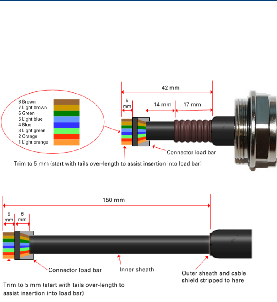
Chapter 5: Installation Supplemental installation information
Supplemental installation information
This section contains detailed installation procedures that are not included in the above topics,
such as how to strip cables, create grounding points and weatherproof connectors.
Stripping drop cable
When preparing drop cable for connection to the PTP 650 ODU or LPU, use the following
measurements:
When preparing drop cable for connection to the PTP 650 PSU (without a cable gland), use the
following measurements:
UNDER DEVELOPMENT
Page 5-58
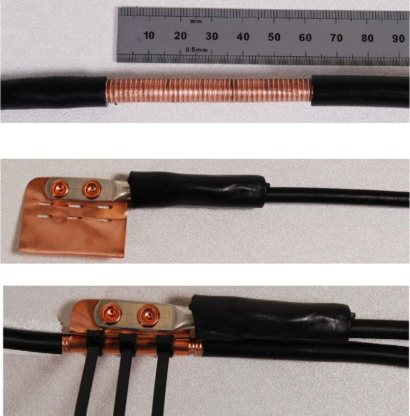
Chapter 5: Installation Supplemental installation information
Creating a drop cable grounding point
Use this procedure to connect the screen of the main drop cable to the metal of the supporting
structure using the cable grounding kit (Cambium part number 01010419001).
To identify suitable grounding points, refer to Drop cable grounding points on page 3-17.
1
Remove 60
mm (2.5 inches) of the drop cable outer sheath.
2
Cut 38mm (1.5 inches) of rubber tape (
self-amalgamating) and fit to the ground cable lug.
Wrap the tape completely around the lug and cable.
3
Fold the ground wire strap around the drop cable screen and fit cable ties.
UNDER DEVELOPMENT
Page 5-59
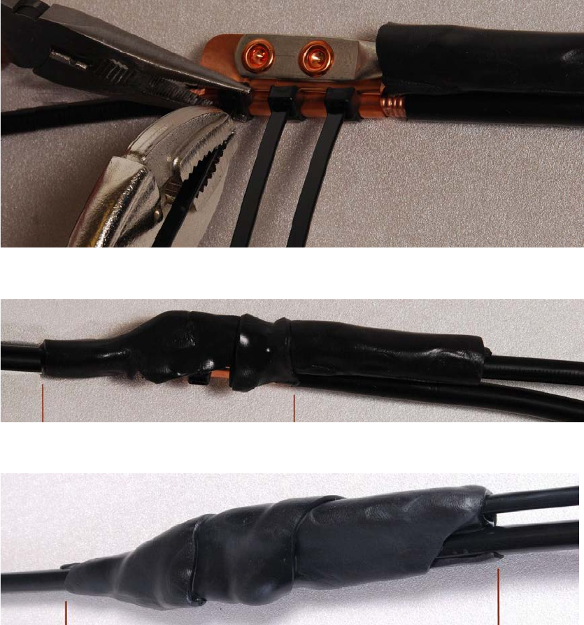
Chapter 5: Installation Supplemental installation information
4
Tighten the cable ties with pliers.
Cut the surplus from the cable ties.
5
Cut a
38mm (1.5 inches) section of self-amalgamating tape and wrap it completely around the
joint between the drop and ground cables.
6
Use the remainder of the self
-amalgamating tape to wrap the complete assembly. Press the
tape edges together so that there
are no gaps.
UNDER DEVELOPMENT
Page 5-60
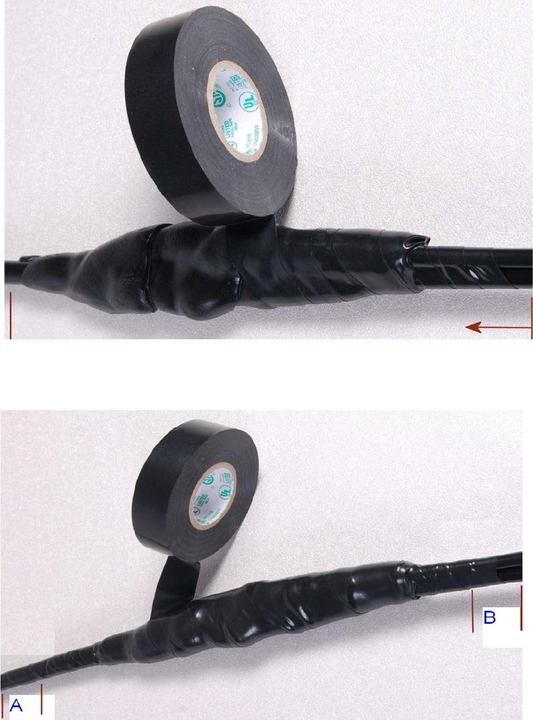
Chapter 5: Installation Supplemental installation information
7
Wrap a layer of
PVC tape from bottom to top, starting from 25 mm (1 inch) below and
finishing 25
mm (1 inch) above the edge of the self-amalgamating tape, over lapping at half
width.
8
Repeat with a further
four layers of PVC tape, always overlapping at half width. Wrap the
layers in alternate directions (top to bottom, then bottom to top). The edges of each layer
should be 25mm (1 inch) above (A) and 25
mm (1 inch) below (B) the previous layer.
9
Prepare the metal grounding point
of the supporting structure to provide a good electrical
contact with the grounding cable
clamp. Remove paint, grease or dirt, if present. Apply anti-
oxidant compound liberally between the two metals.
UNDER DEVELOPMENT
Page 5-61
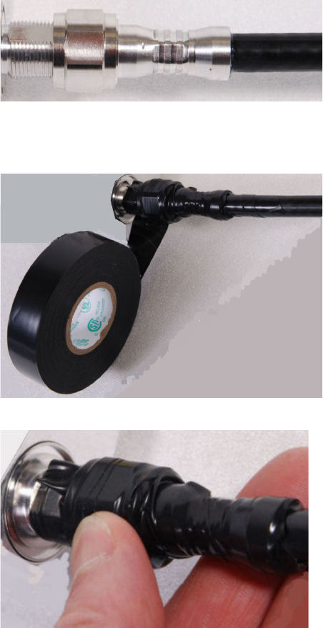
Chapter 5: Installation Supplemental installation information
10
Clamp the bottom lug of the grounding cable to the
supporting structure using site approved
methods.
Use a two-hole lug secured with fasteners in both holes. This provides better
protection than a single
-hole lug.
Weatherproofing an N type connector
Use this procedure to weatherproof the N type connectors fitted to the connectorized ODU and
external antenna (if recommended by the antenna manufacturer).
1
Ensure the connection is tight. A torque wrench should be used if available:
2
Wrap the connection with a layer of 19 mm (0.75 inch) PVC tape, starting 25 mm (1 inch)
below the connector body. Overlap the tape to half-width and extend the wrapping to the
body of the LPU. Avoid making creases or wrinkles:
3
Smooth the tape edges:
UNDER DEVELOPMENT
Page 5-62
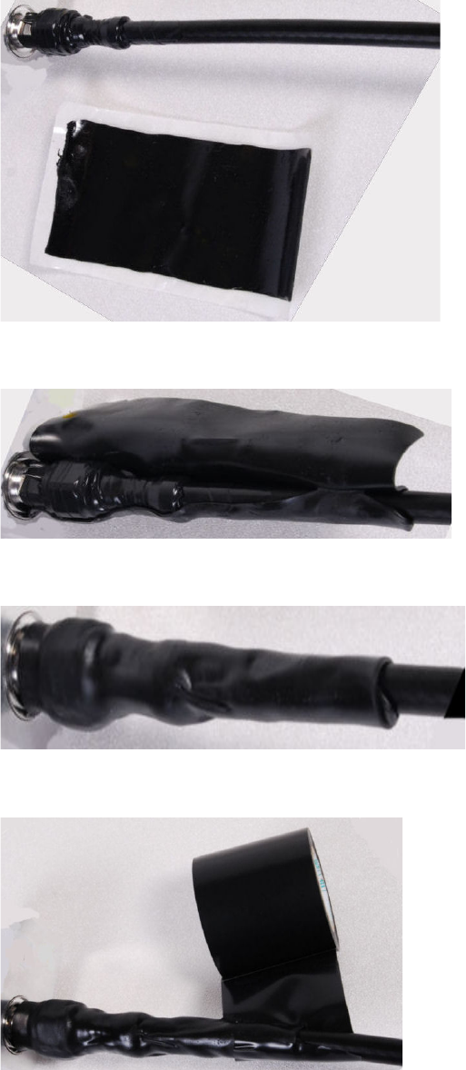
Chapter 5: Installation Supplemental installation information
4
Cut a 125mm (5 inches) length of rubber tape (self-amalgamating):
5
Expand the width of the tape by stretching it so that it will wrap completely around the
connector and cable:
6
Press the tape edges together so that there are no gaps. The tape should extend 25 mm
(1 inch) beyond the PVC tape:
7
Wrap a layer of 50 mm (2 inch) PVC tape from bottom to top, starting from 25 mm (1 inch)
below the edge of the self-amalgamating tape, overlapping at half width.
UNDER DEVELOPMENT
Page 5-63
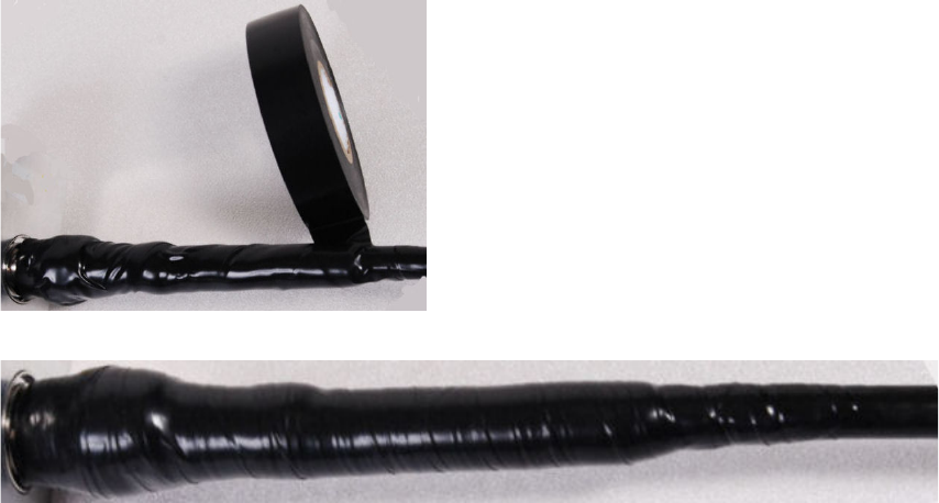
Chapter 5: Installation Supplemental installation information
8
Repeat with a further four layers of 19 mm (0.75 inch) PVC tape, always overlapping at half
width. Wrap the layers in alternate directions:
• Second layer: top to bottom.
• Third layer: bottom to top.
• Fourth layer: top to bottom.
• Fifth layer: bottom to top.
The bottom edge of each layer should be 25 mm (1 inch) below the previous layer.
9
Check the completed weatherproof connection:
UNDER DEVELOPMENT
Page 5-64
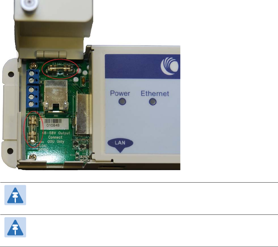
Chapter 5: Installation Supplemental installation information
Replacing PSU fuses
The AC+ DC Enhanced Power Injector contains two replaceable fuses. These fuses protect the
positive and negative grounded DC input voltages. If an incorrect power supply (that is, not in the
range 37V to 60V DC) is connected to the DC input terminals, one or both fuses may blow.
Both fuses are 3 Amp slow-blow, for example Littlefuse part number 0229003.
To replace these fuses, undo the retaining screw and hinge back the cover as indicated:
Note
No other fuses are replaceable in the AC+DC Enhanced Power Injector.
Note
The AC Power Injector does not contain replaceable fuses.
UNDER DEVELOPMENT
Page 5-65