Cambium Networks 54100 Fixed Point to Point Wireless Bridge User Manual PTP 600 Series User Guide
Cambium Networks Limited Fixed Point to Point Wireless Bridge PTP 600 Series User Guide
UserManual.wiki
>
Cambium Networks
>
54100 User Manual
>
Manual 2
Contents
1.
User Manual Revised
2.
User Manual Part 1
3.
User Manual Part 2
4.
Manual 1
5.
Manual 2
Manual 2
Navigation menu
Upload a User Manual
Namespaces
Wiki Guide
HTML
PDF
Info
Views
User Manual
Discussion / Help
Navigation
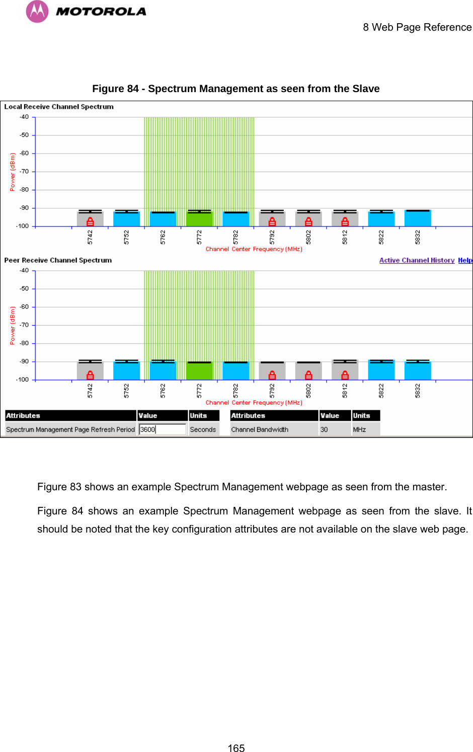
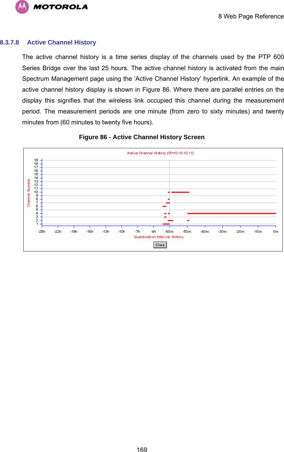
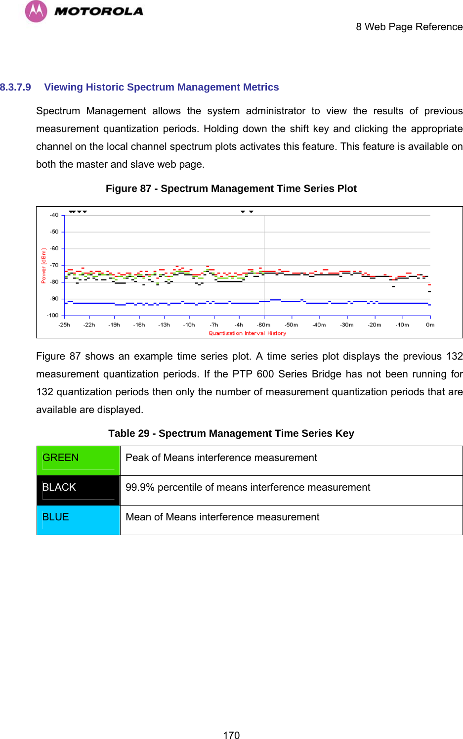
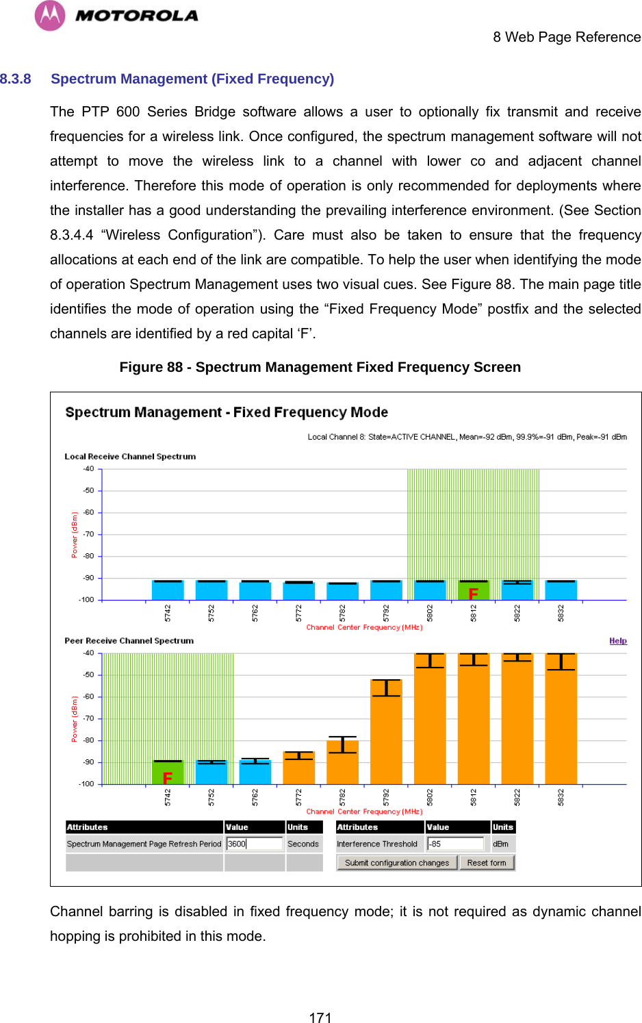
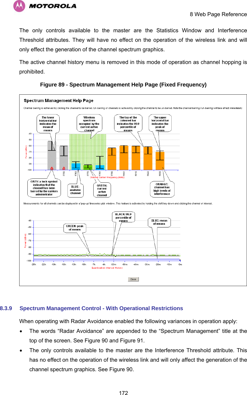

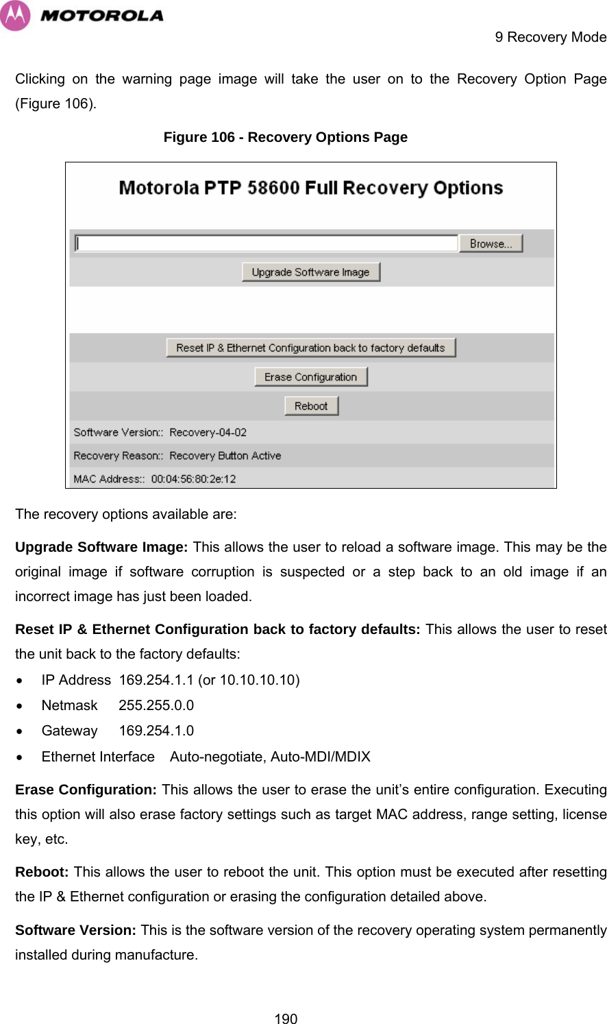
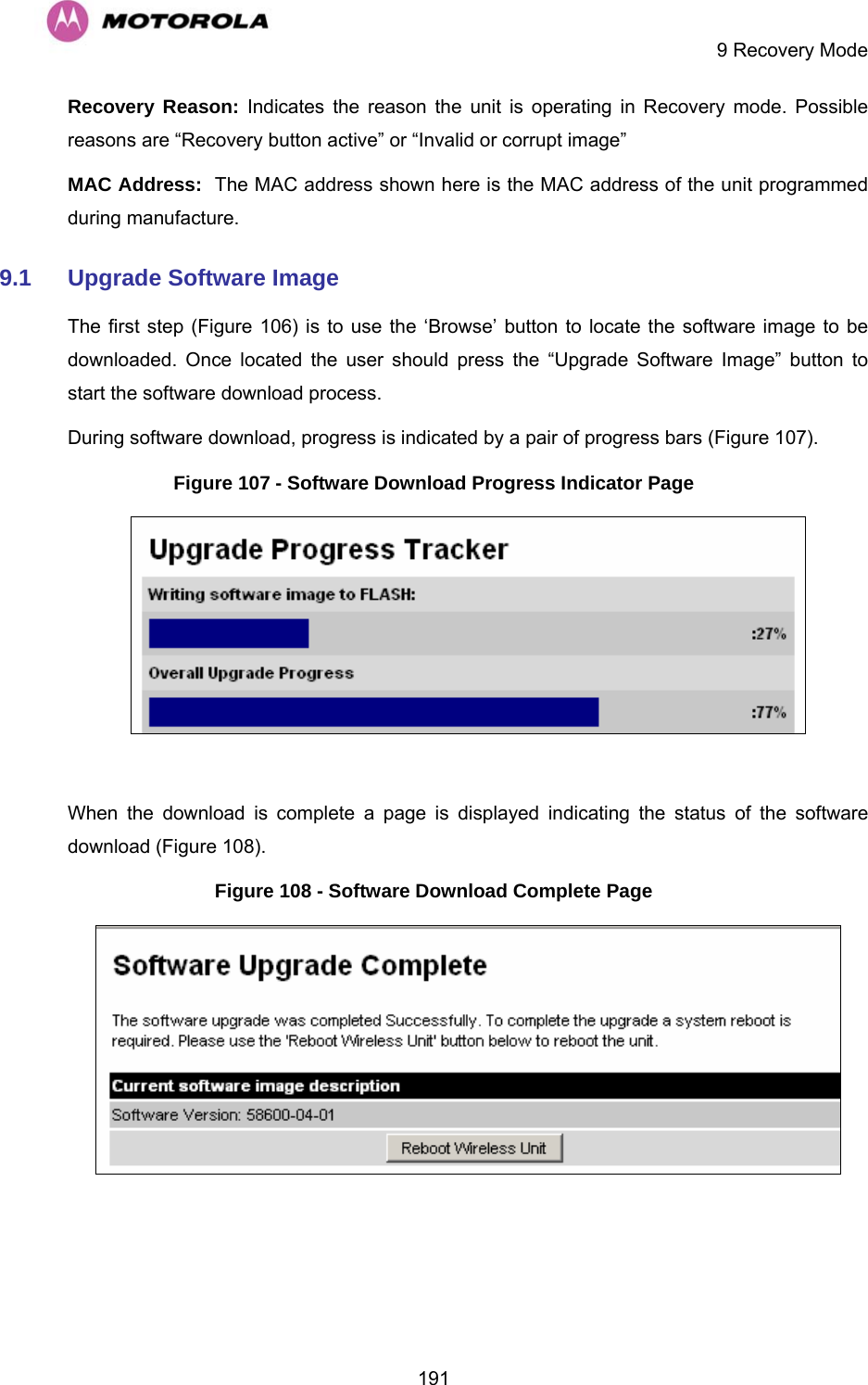
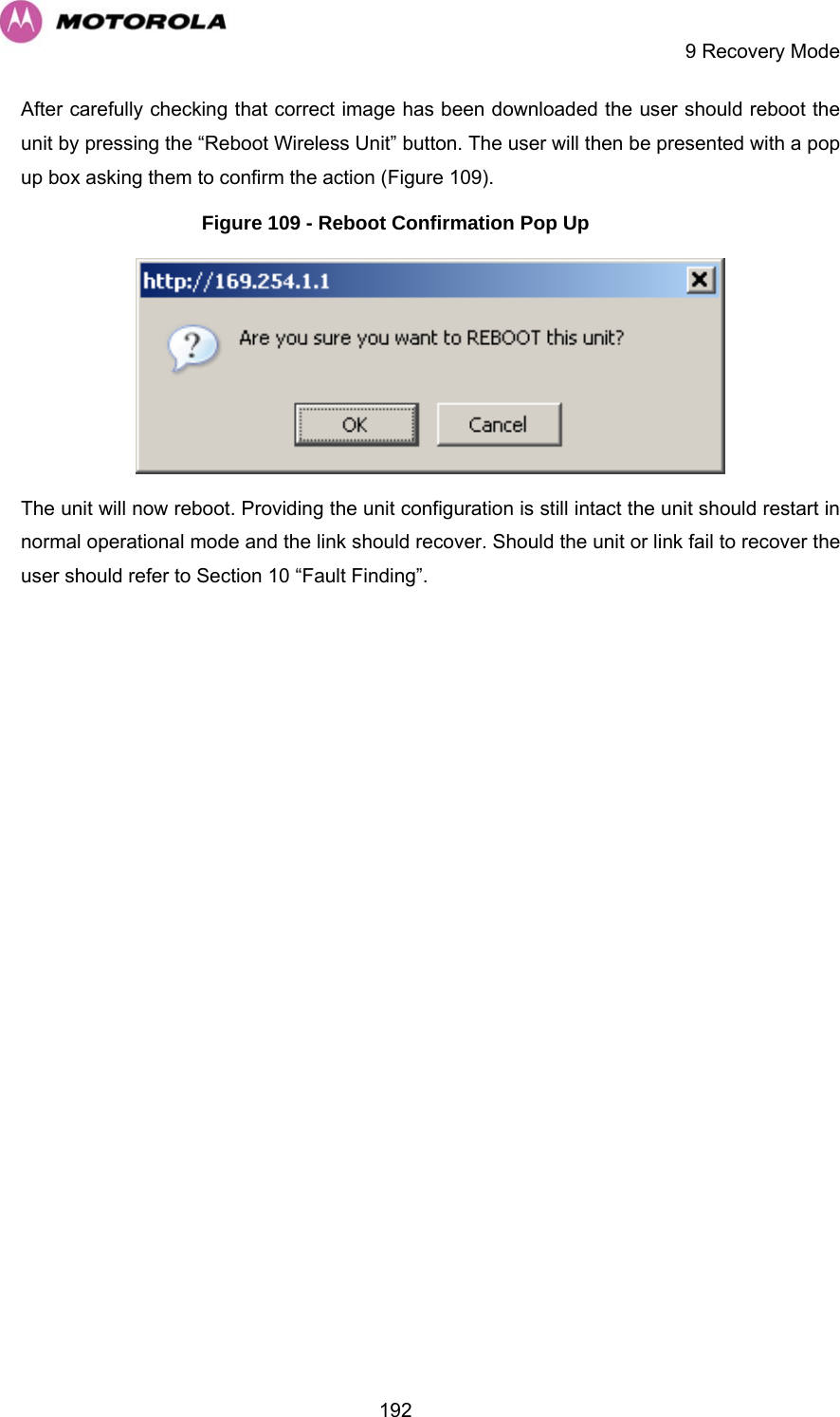
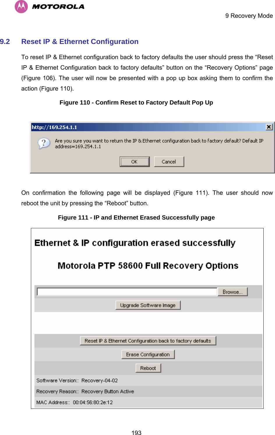
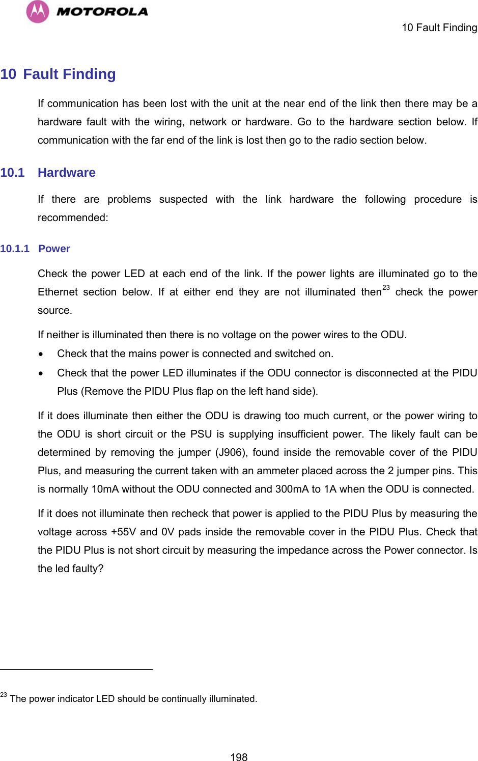
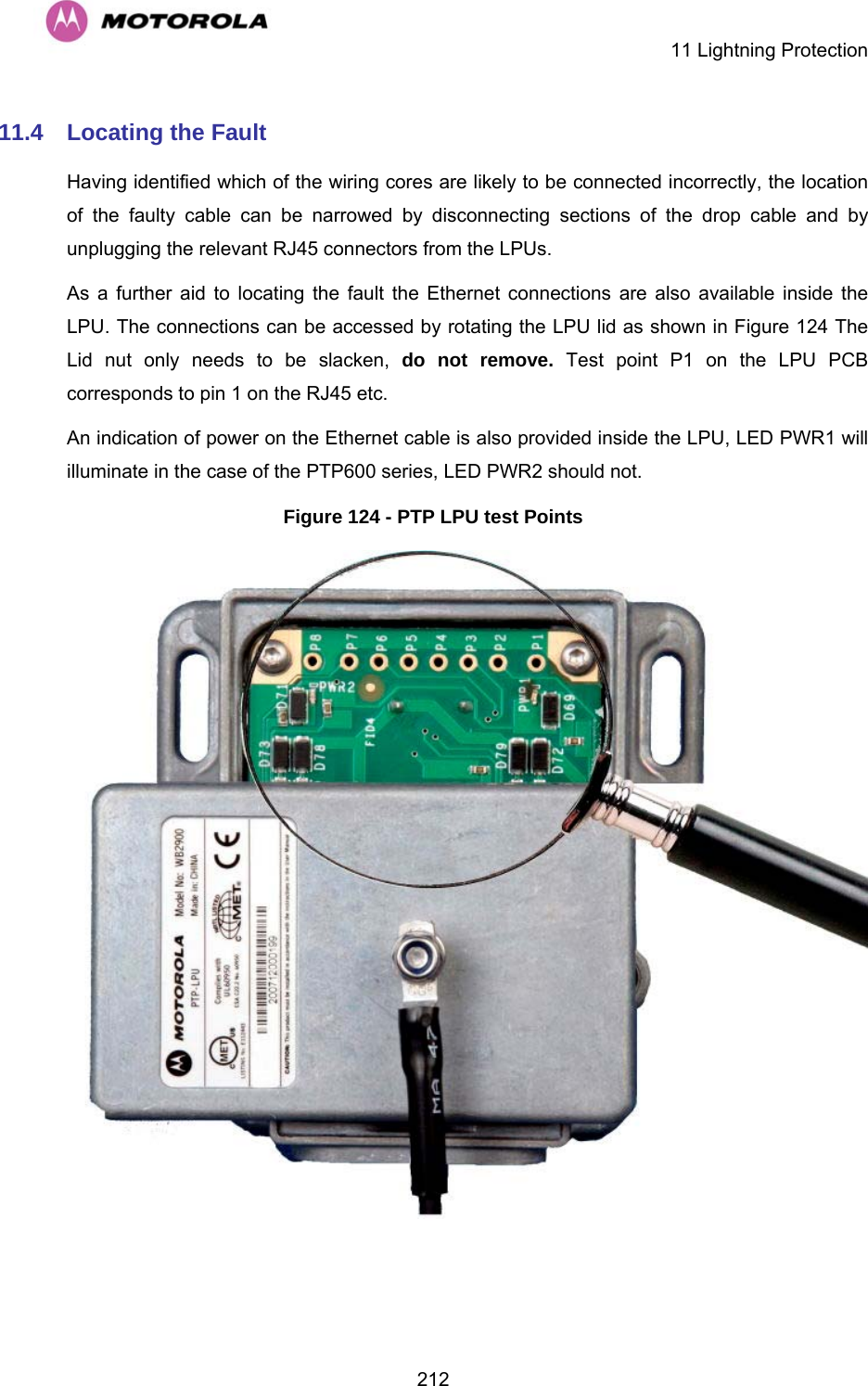
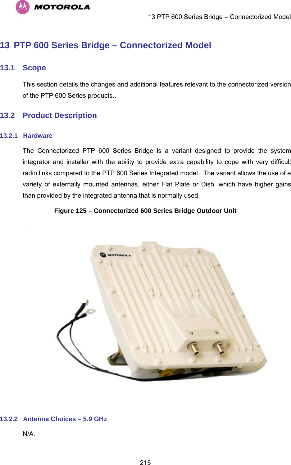
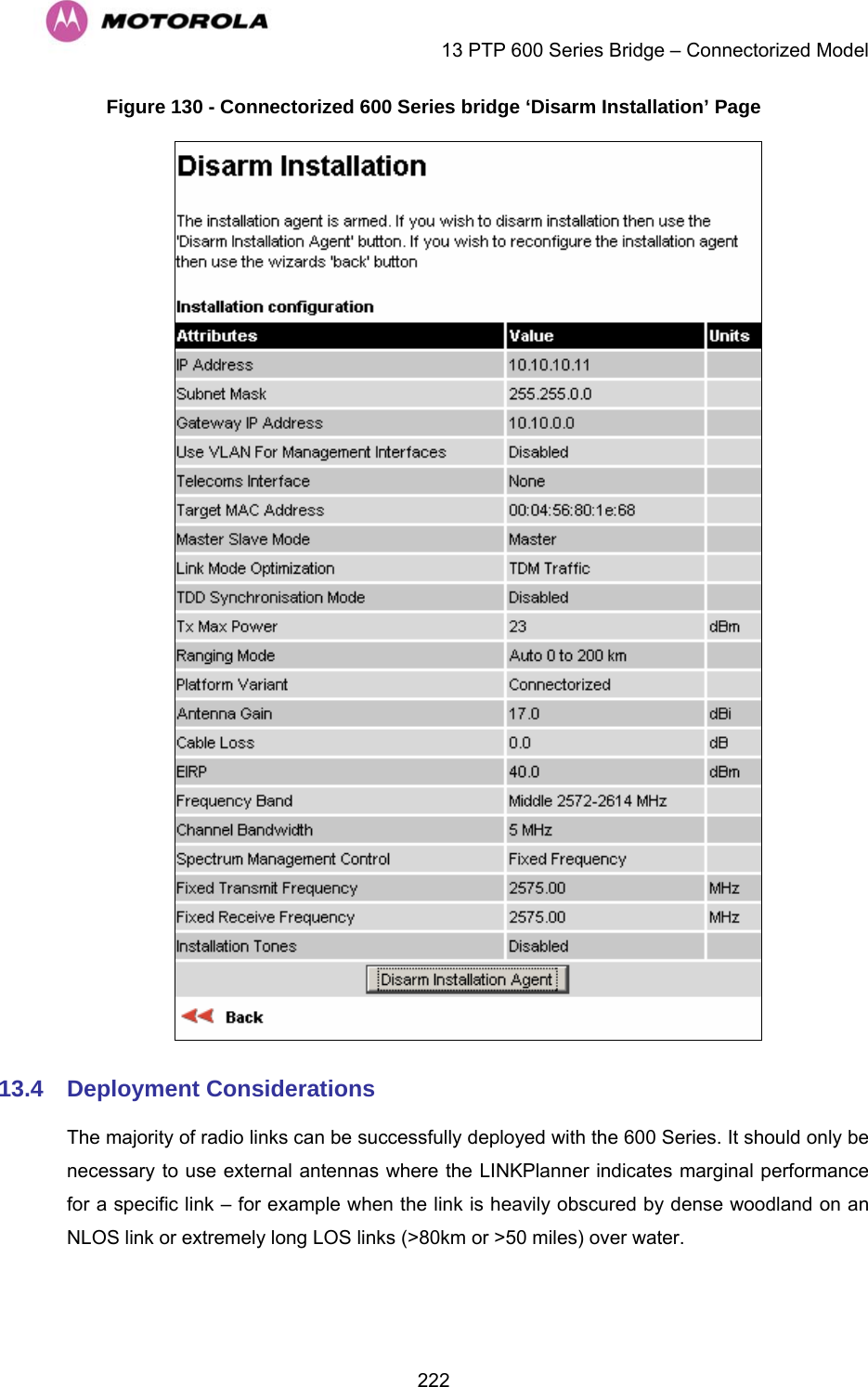
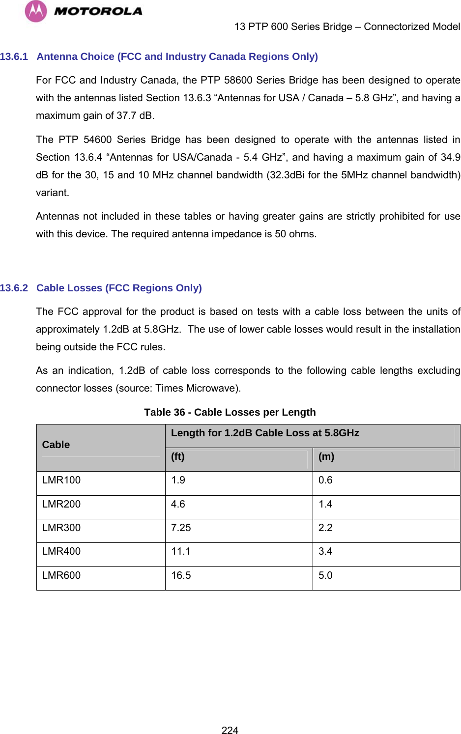
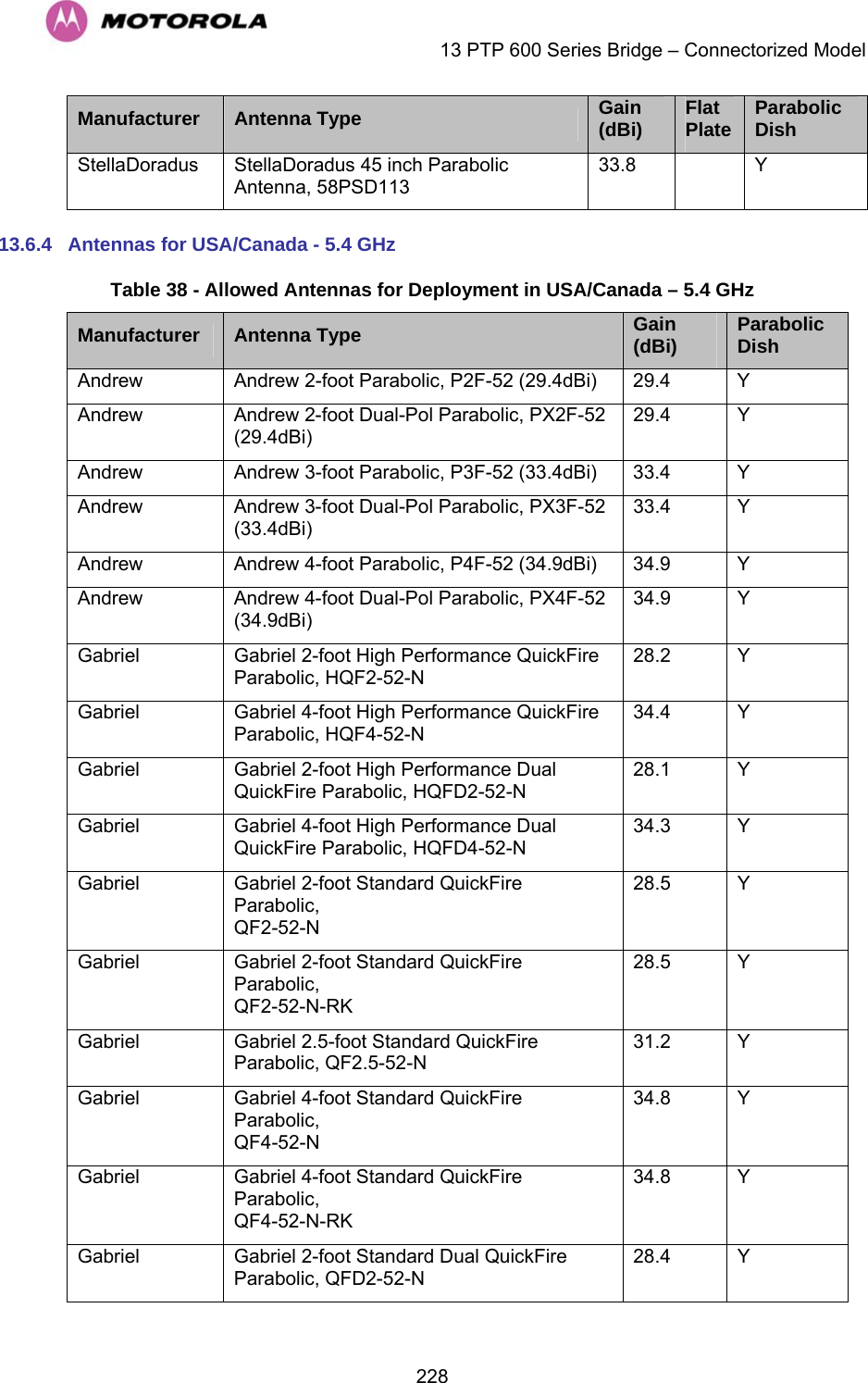
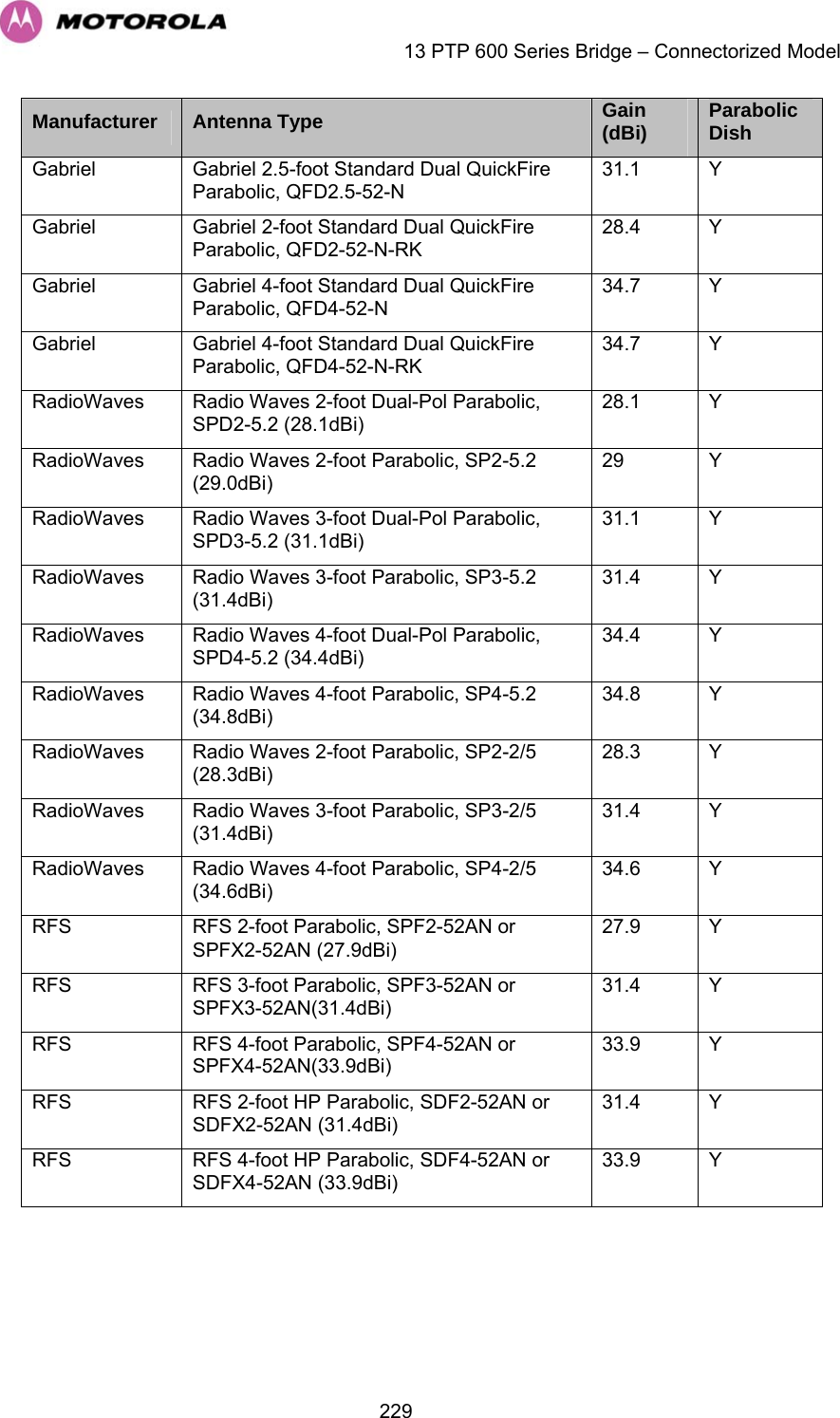
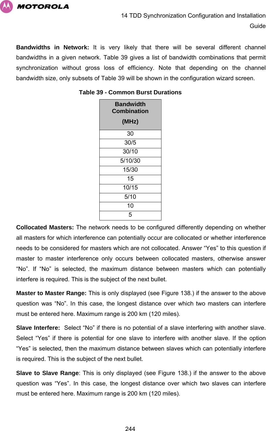
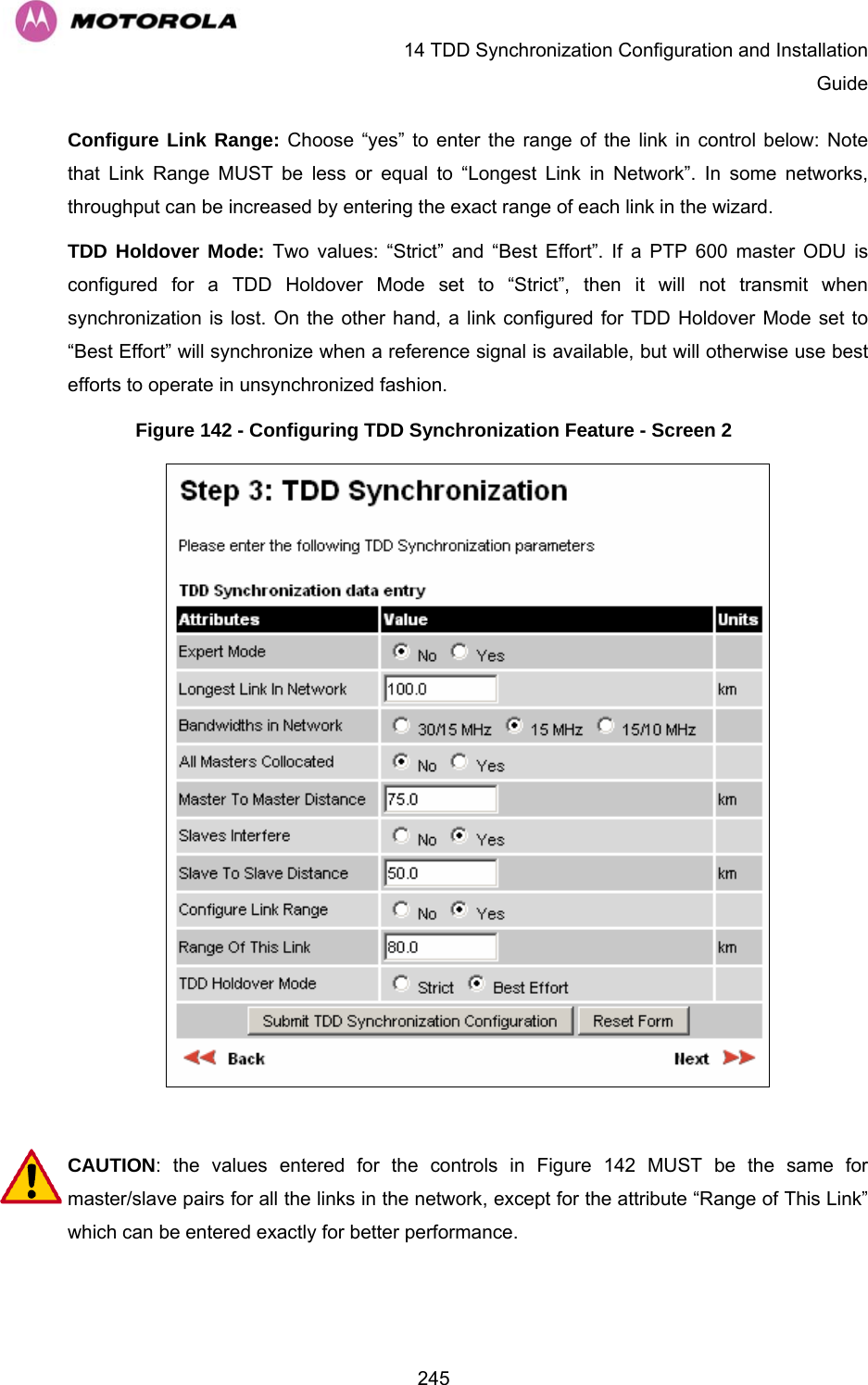
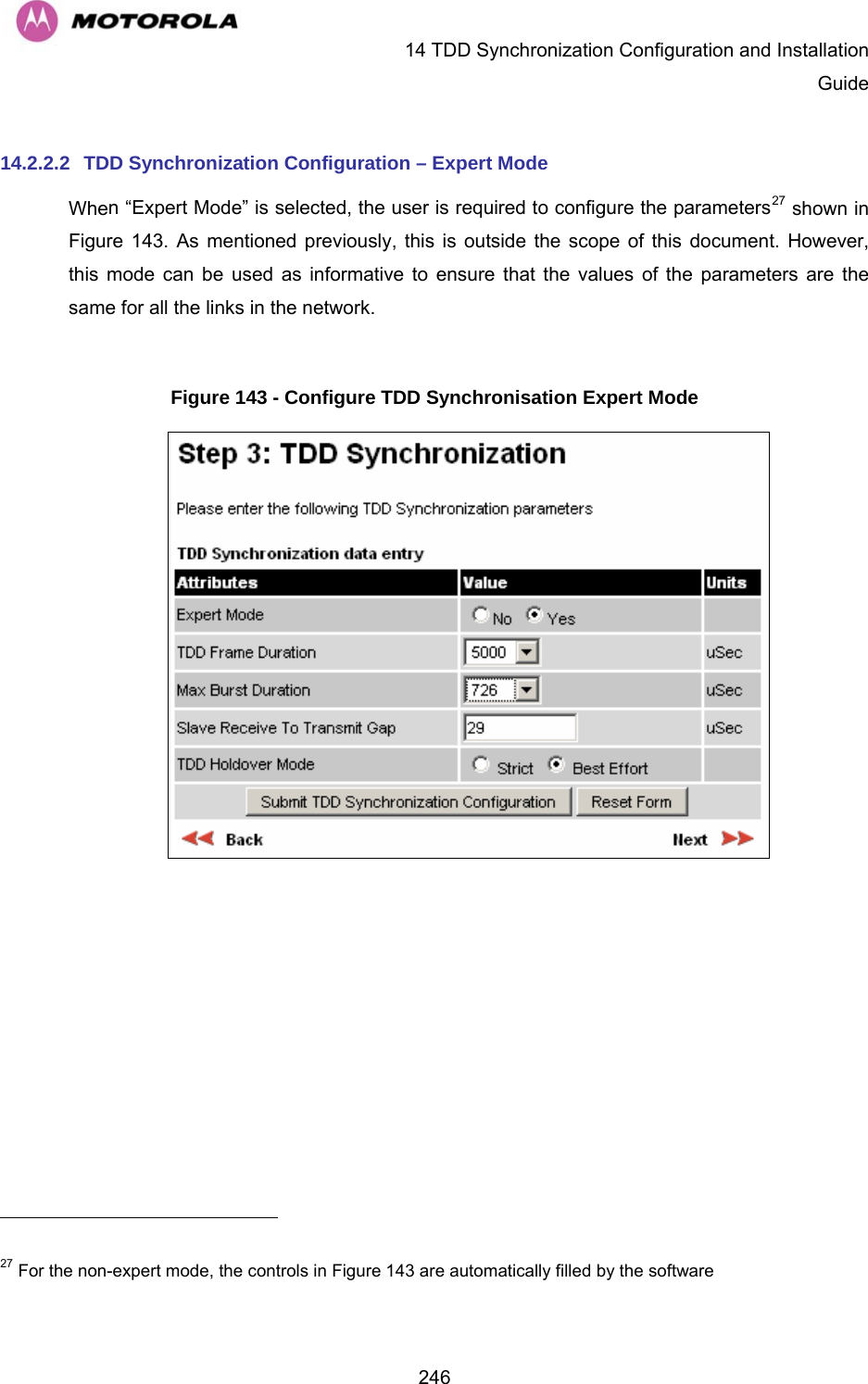
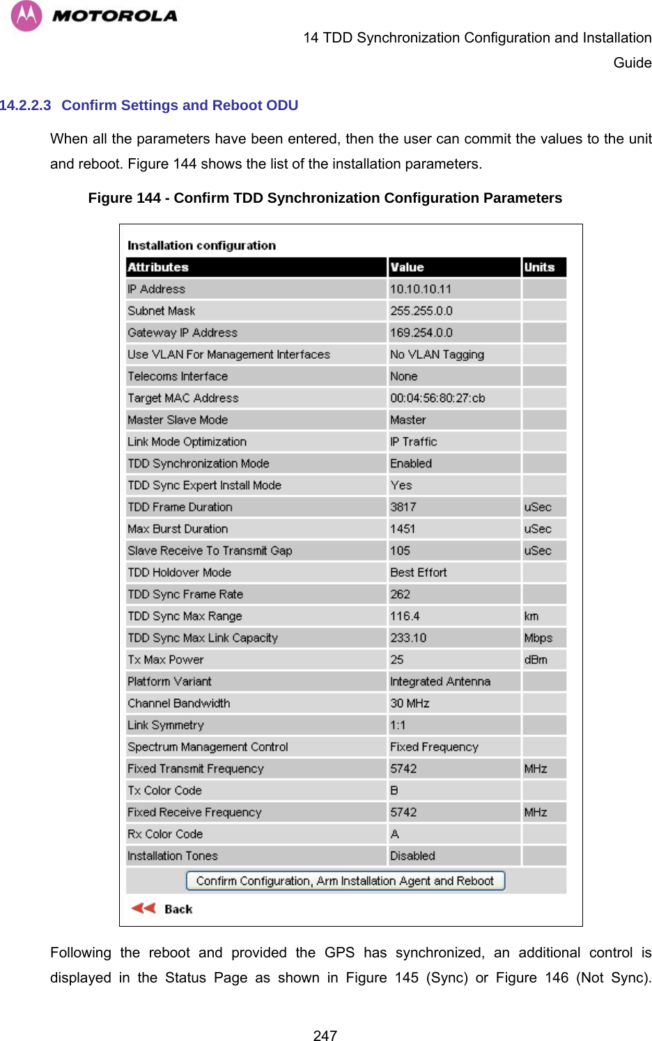
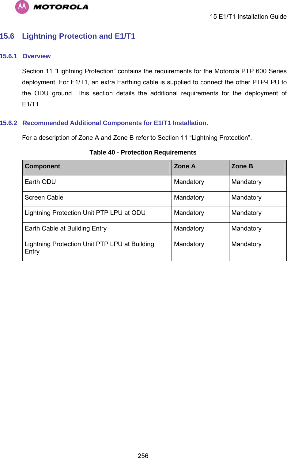
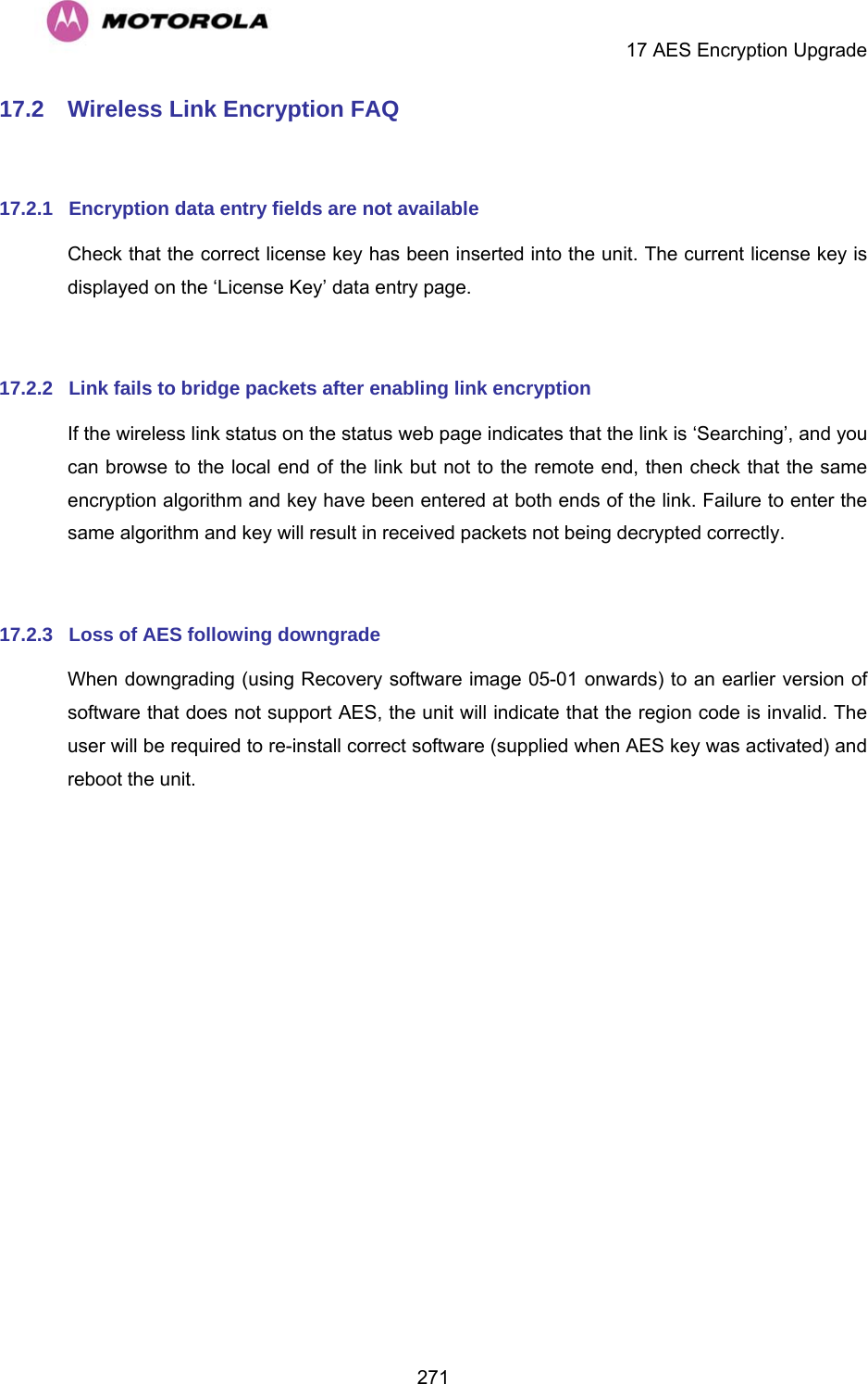
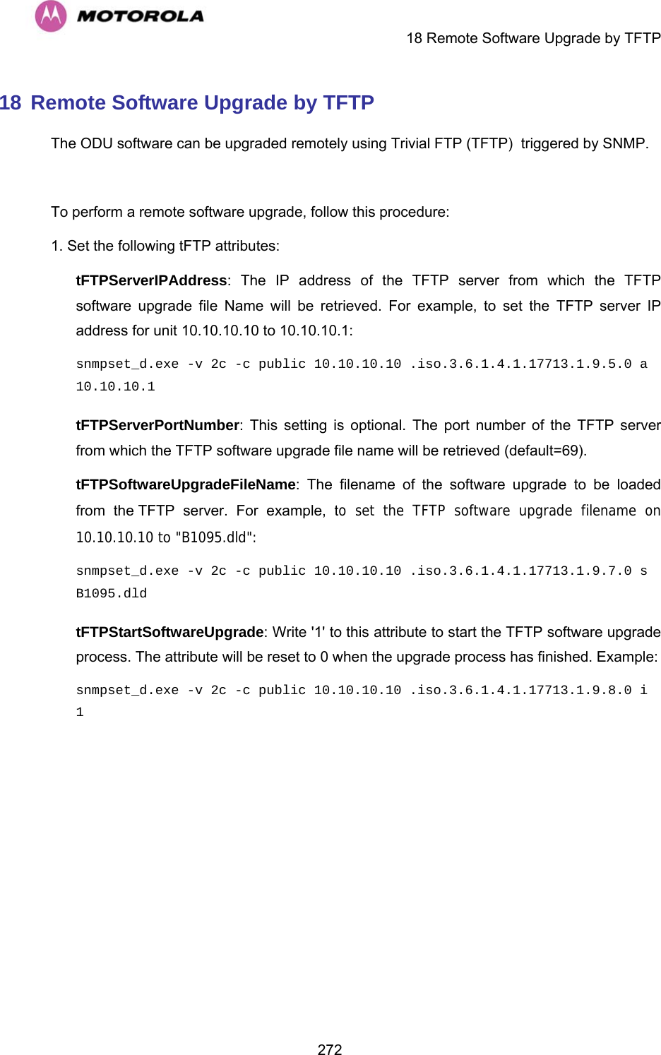
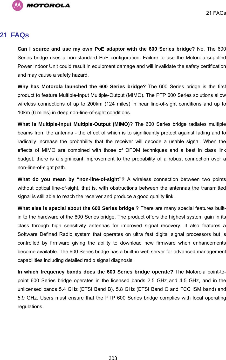
![13 PTP 600 Series Bridge – Connectorized Model 223The external antennas can be either dual-polarization (as the integrated antenna) or two single polarized antennas can be used in a spatially diverse configuration. It is expected that the dual-polarization antennas would normally be used to simplify the installation process; spatially diverse antennas may provide additional fade margin on very long LOS links where there is evidence of correlation of the fading characteristics on Vertical and Horizontal polarizations. Dual polarization antennas (with a gain greater than the integrated antenna) are currently only available in parabolic dish form. 13.5 Link Budget An estimate of the link budget for a specific application can be obtained by using the Motorola Systems link estimation tools. For more information see the Motorola web site. 13.6 Regulatory Issues Installations must conform to any applicable local regulations for the Equivalent Isotropic Radiated Power (EIRP). Ensuring compliance becomes more complex when the connectorized unit is used with external antennas which may be locally sourced. With higher gain external antennas fitted, the Maximum Transmit power may need to be reduced for operation in specific countries. See Section 5.2 “Licenses and Region Codes” for any EIRP restrictions that may apply in your region. In some regions, operation of the PTP 54600 products is constrained by an EIRP limit. The normal constraint is that the EIRP does not exceed 30 dBm (33 dBm for PTP 58600) for radio signals with a bandwidth of >=20 MHz. As the PTP 54600 operating bandwidth is approximately 27 MHz, then the limit is 30 dBm EIRP (33 dBm for PTP 58600). When operating with external antennas, the installer/operator has to set the maximum transmit power to ensure that the EIRP limit is not exceeded. The Set_Max_Transmit_Power is calculated as below: Set_Max_Transmit_Power = [Max_Transmit_Power] rounded down to nearest lower dB.](https://usermanual.wiki/Cambium-Networks/54100.Manual-2/User-Guide-1015512-Page-75.png)