Cambium Networks 54100 Fixed Point to Point Wireless Bridge User Manual PTP 400 Series User Guide
Cambium Networks Limited Fixed Point to Point Wireless Bridge PTP 400 Series User Guide
Contents
- 1. User Manual Revised
- 2. User Manual Part 1
- 3. User Manual Part 2
- 4. Manual 1
- 5. Manual 2
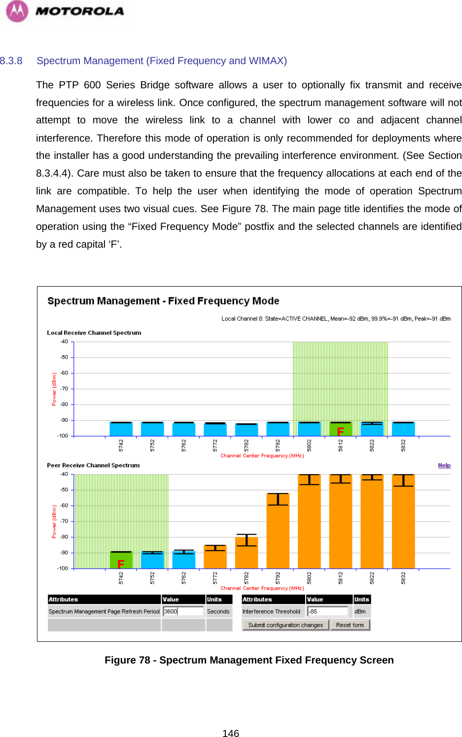
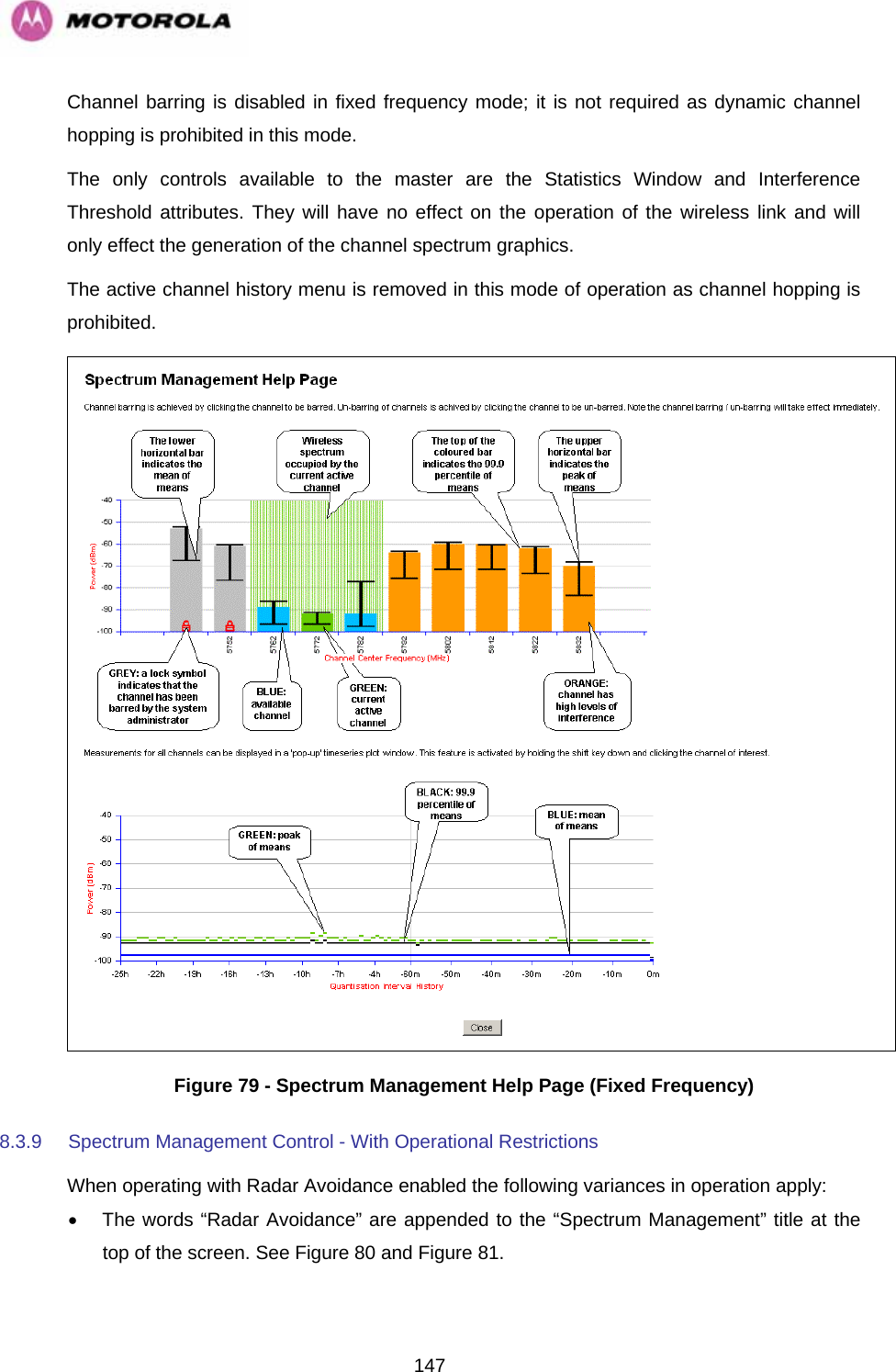
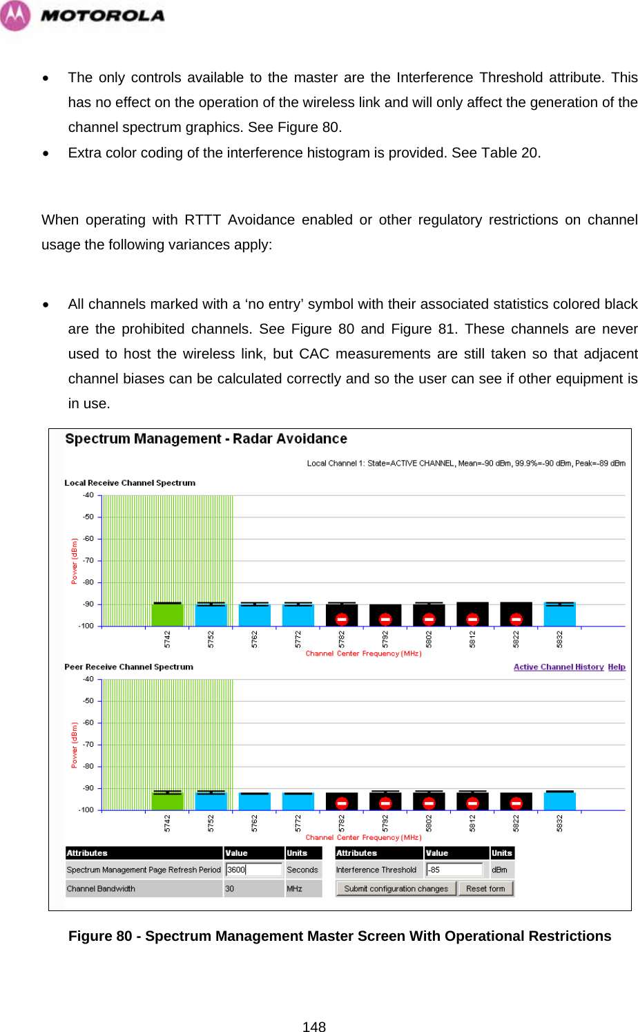
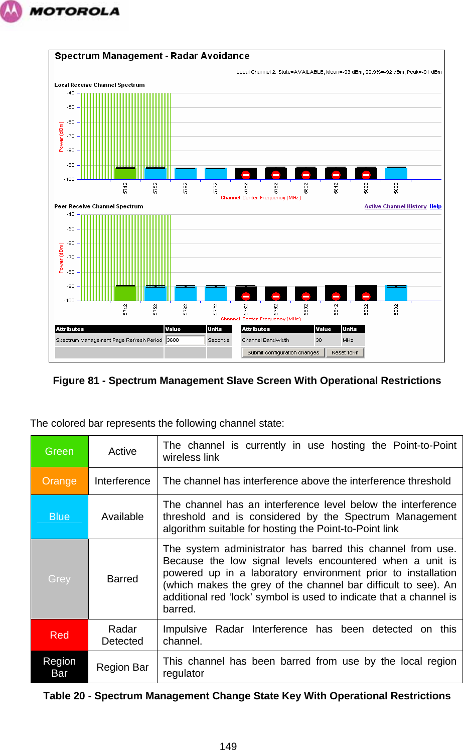
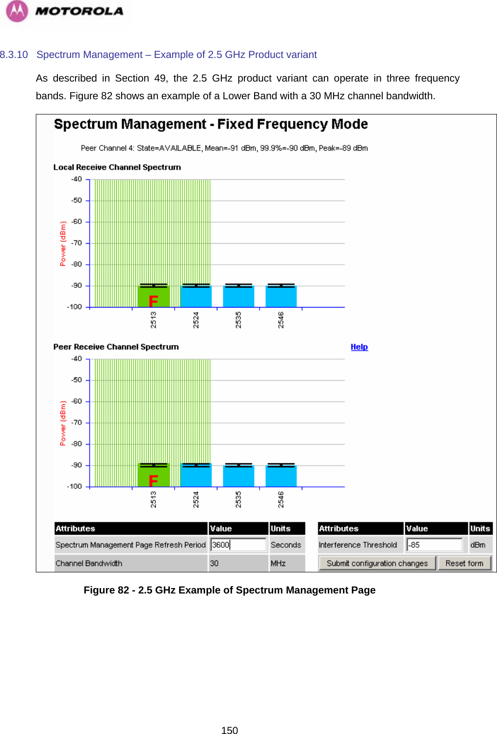
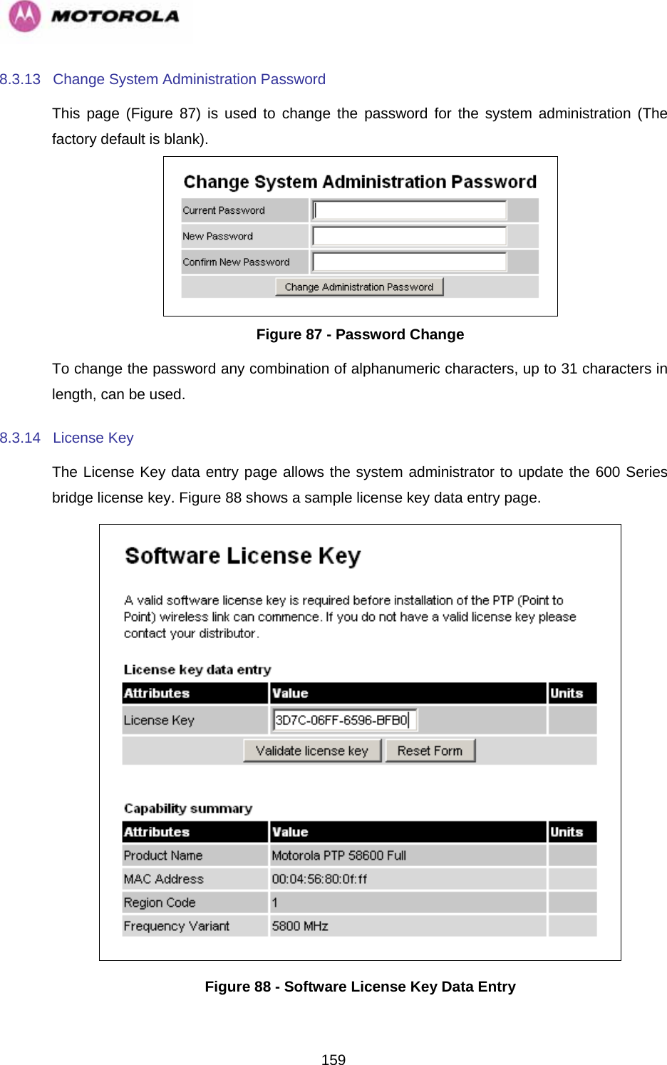
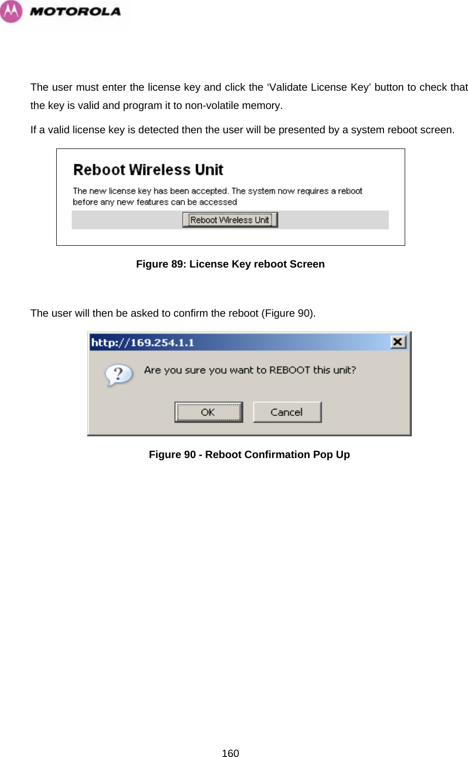
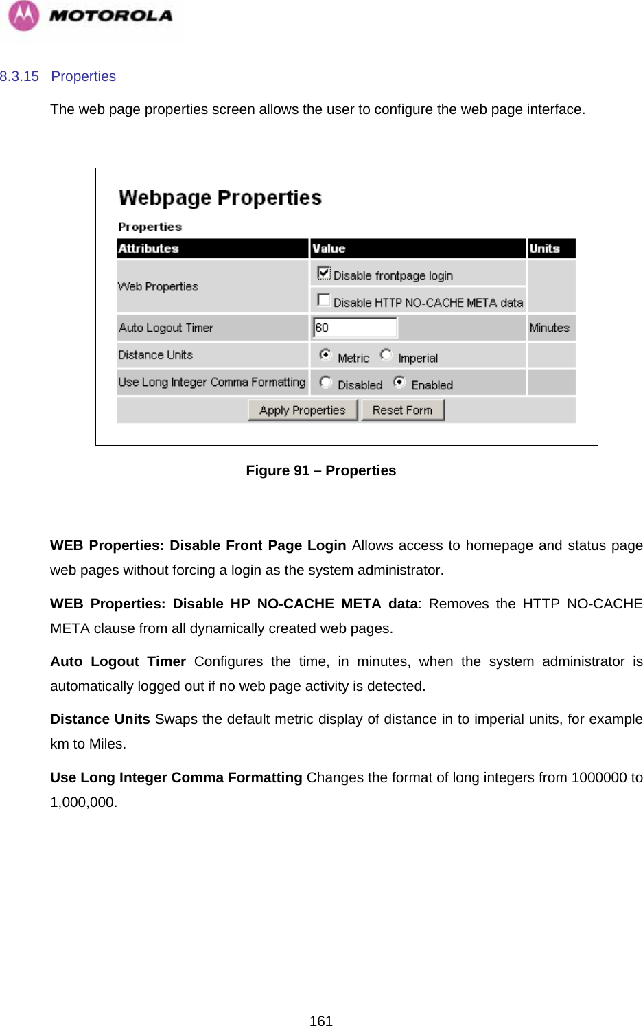
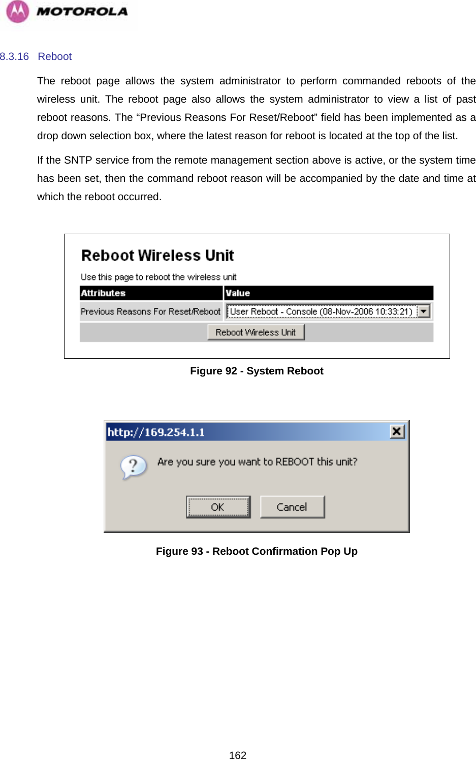
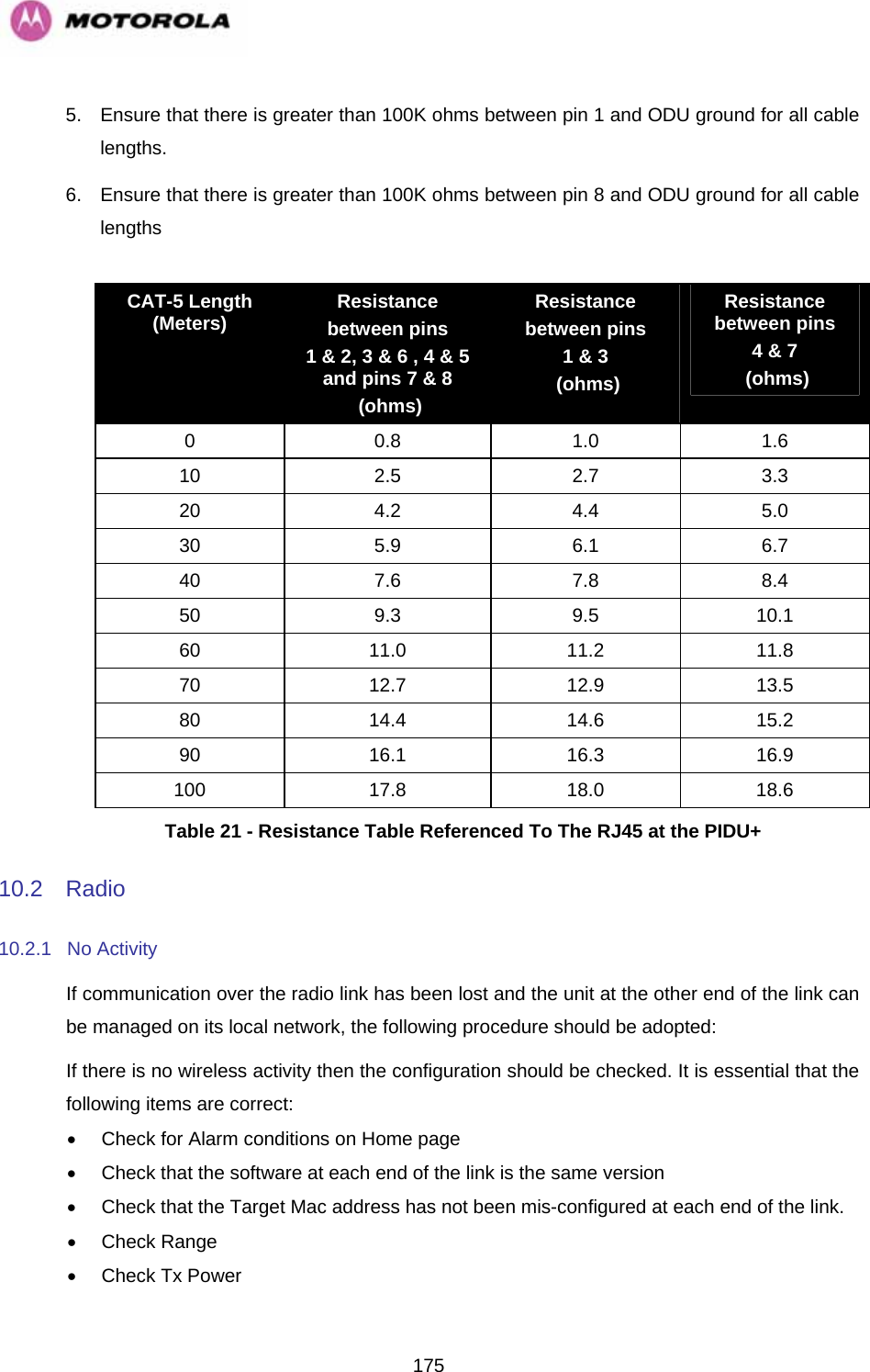
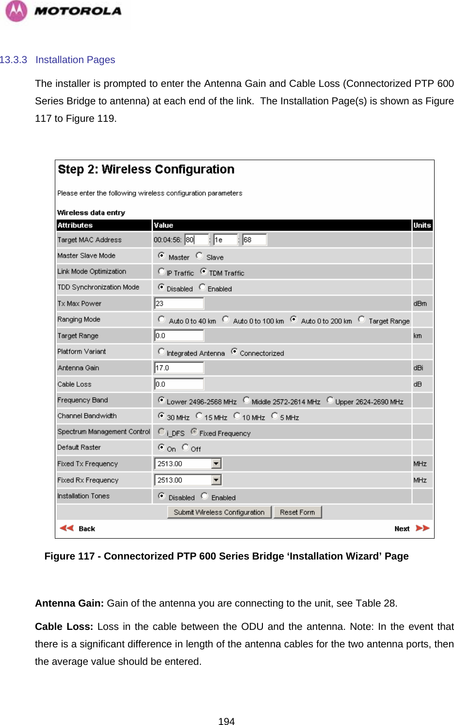
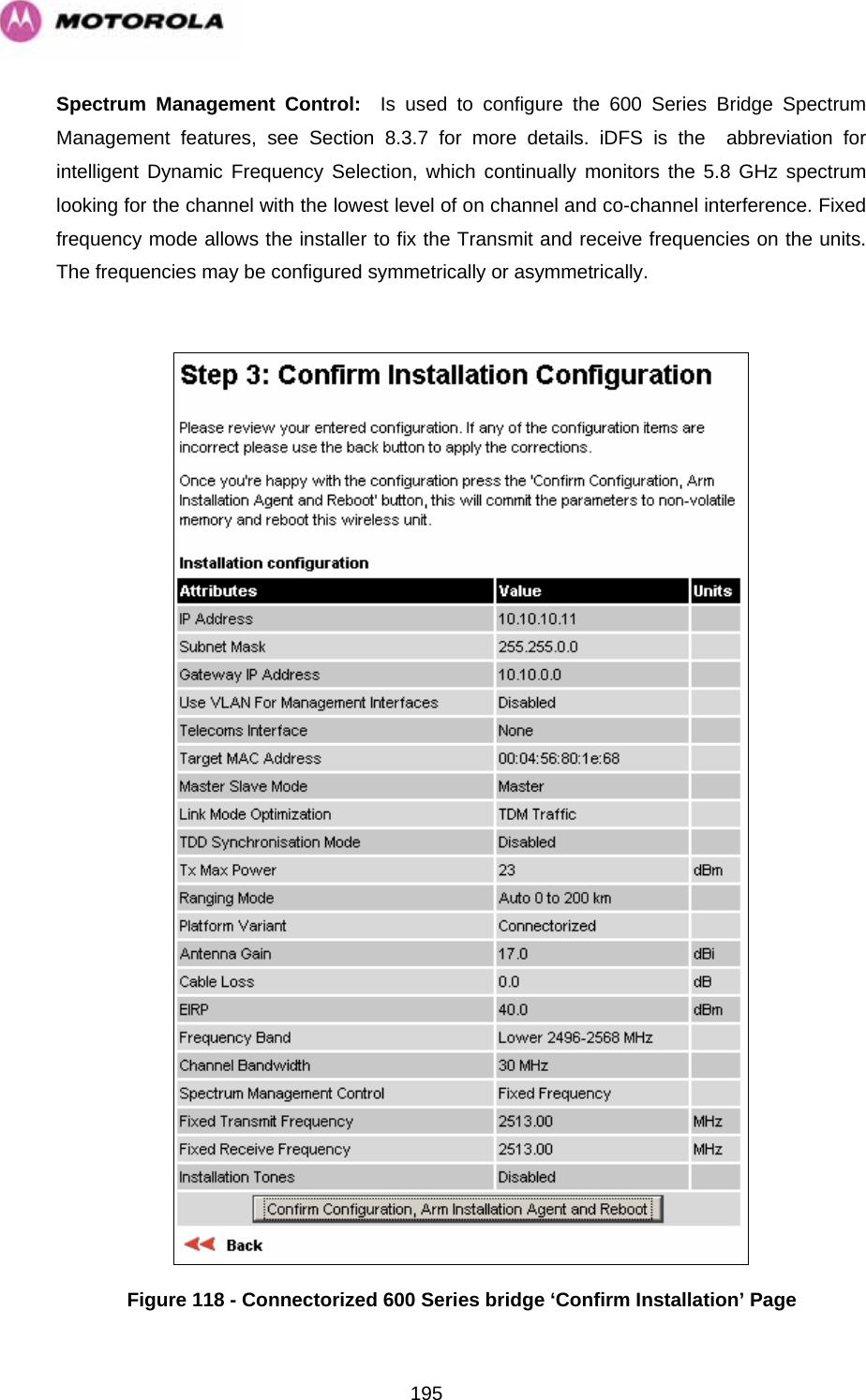
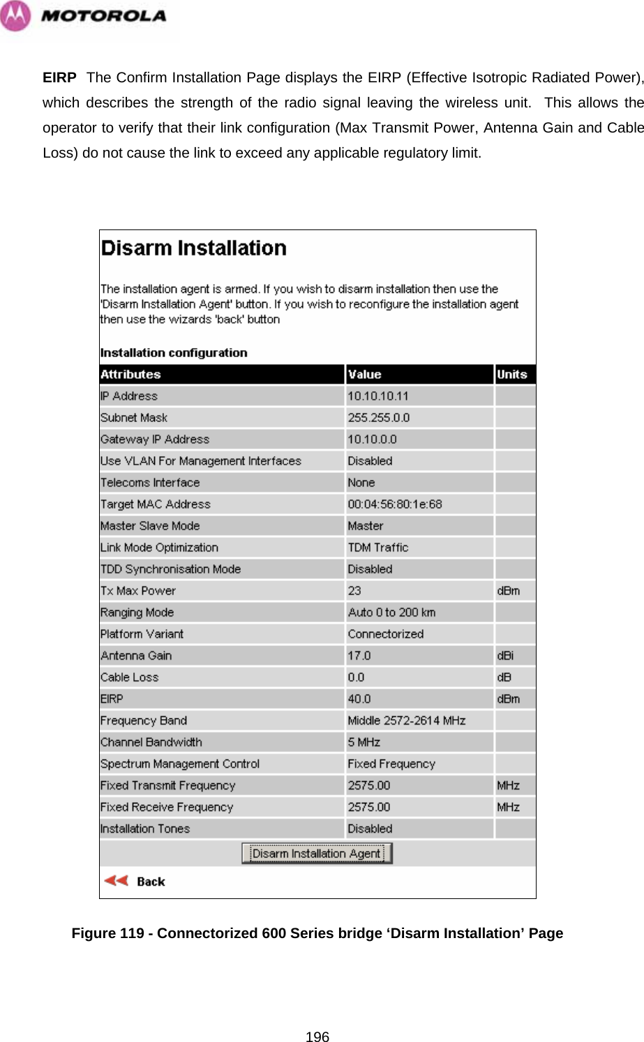
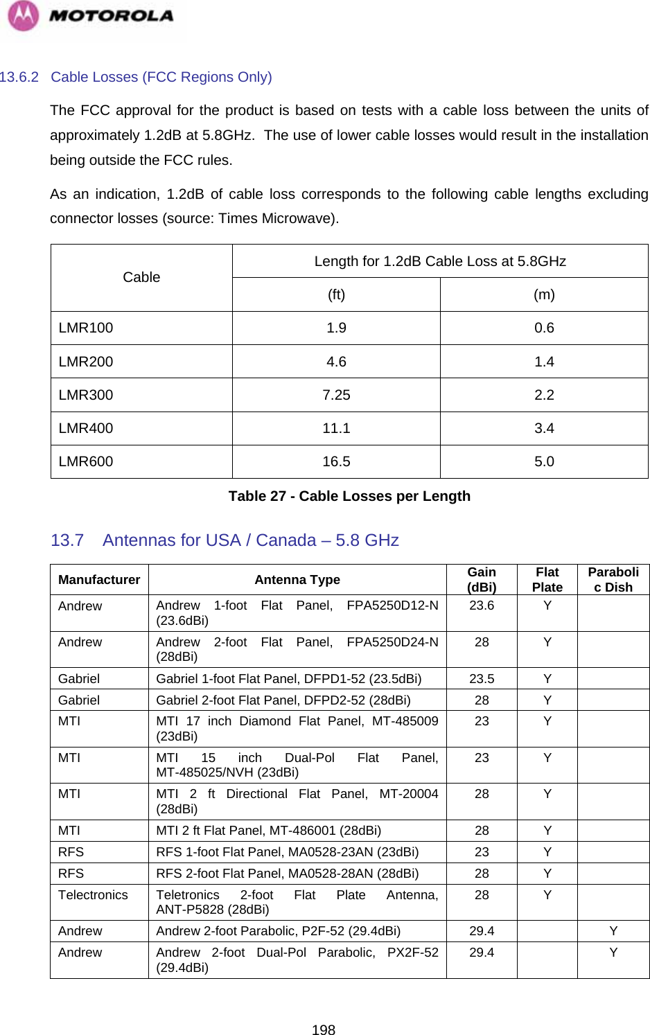
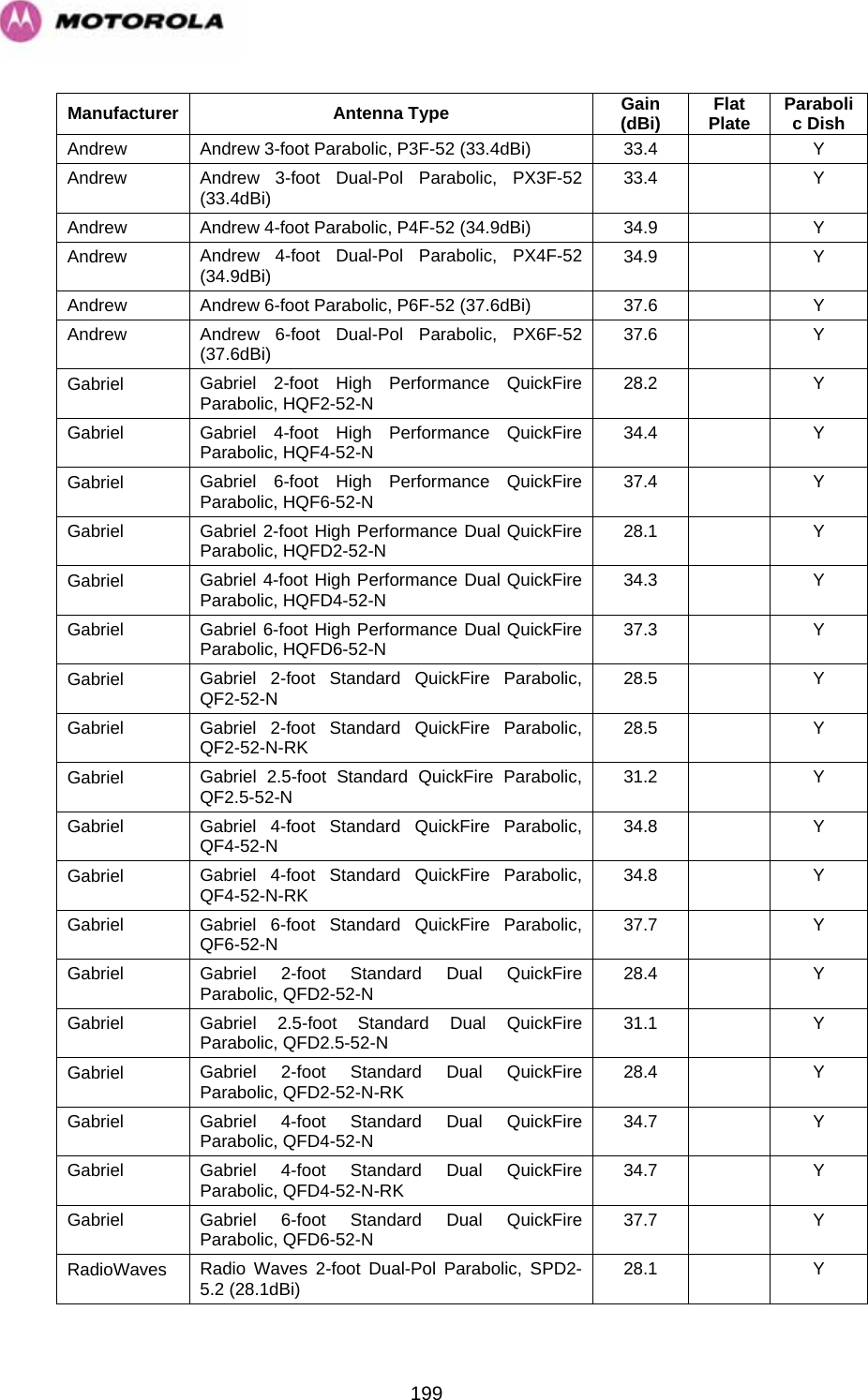
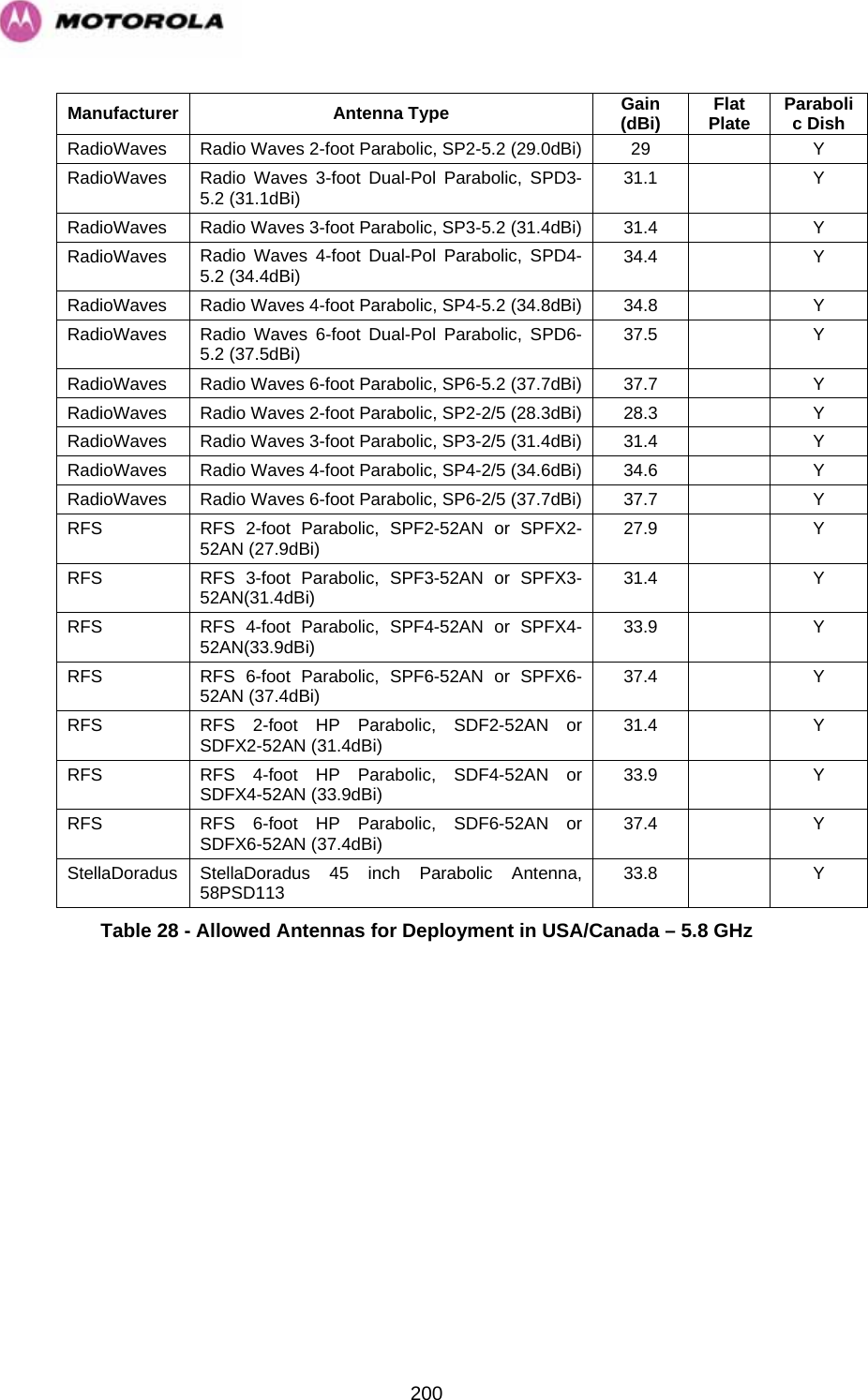
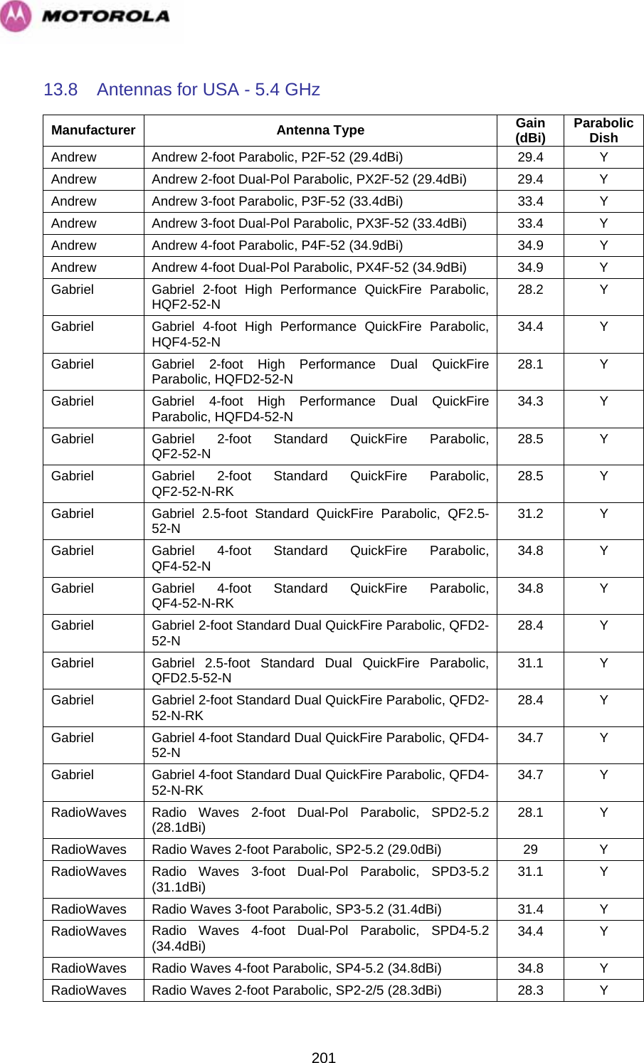
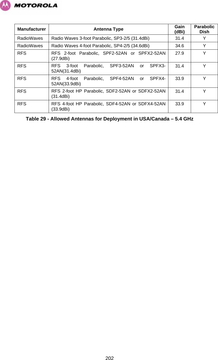
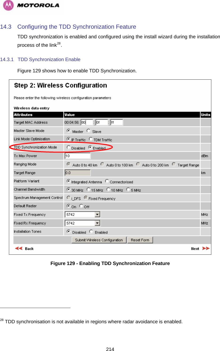
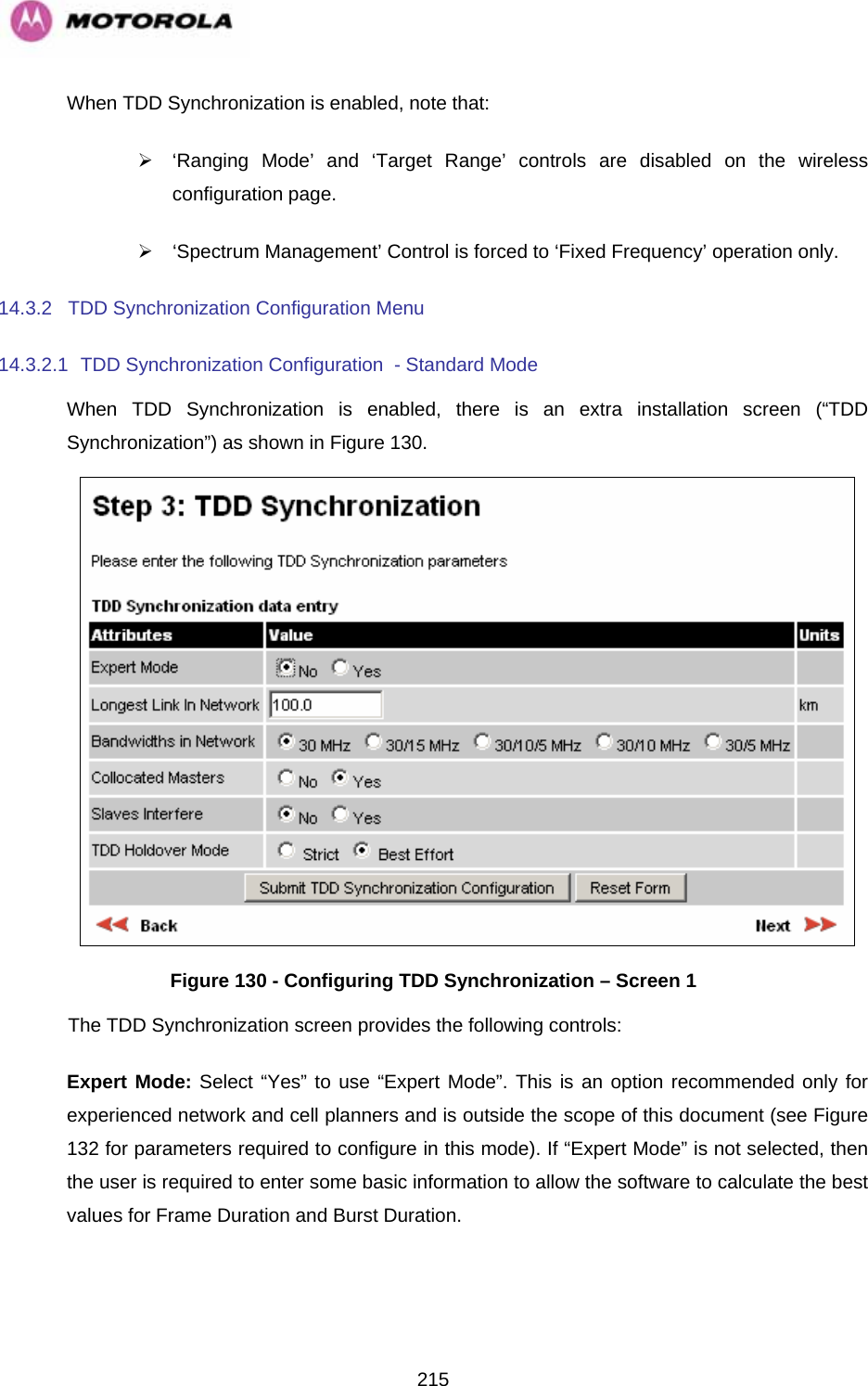
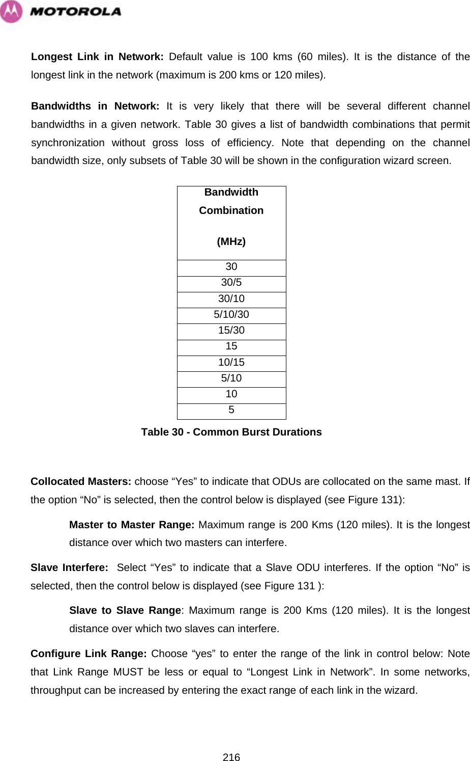
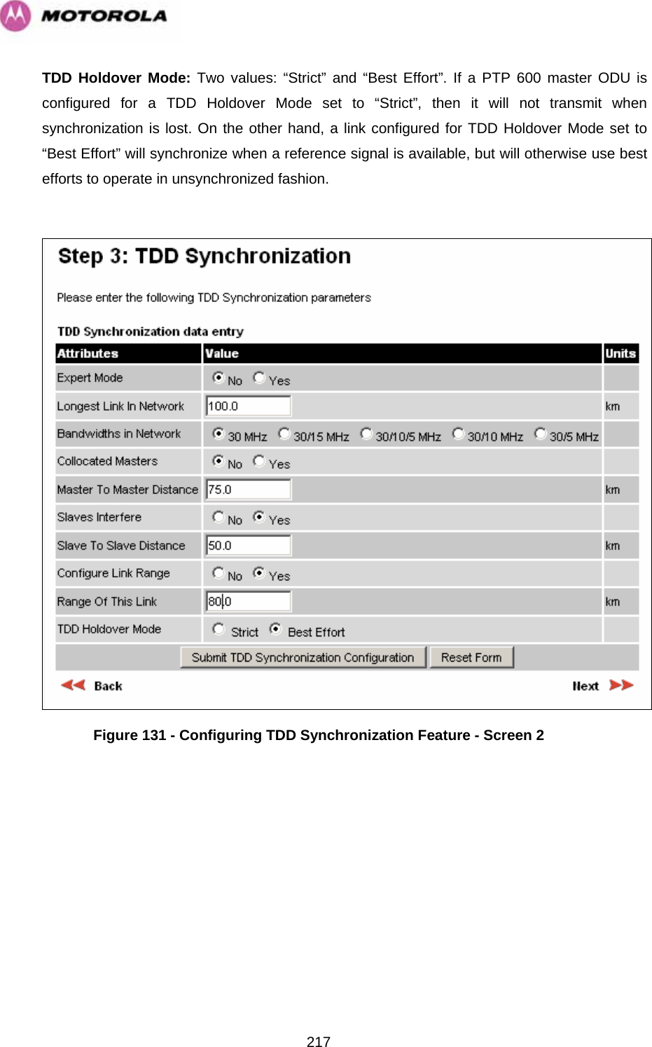
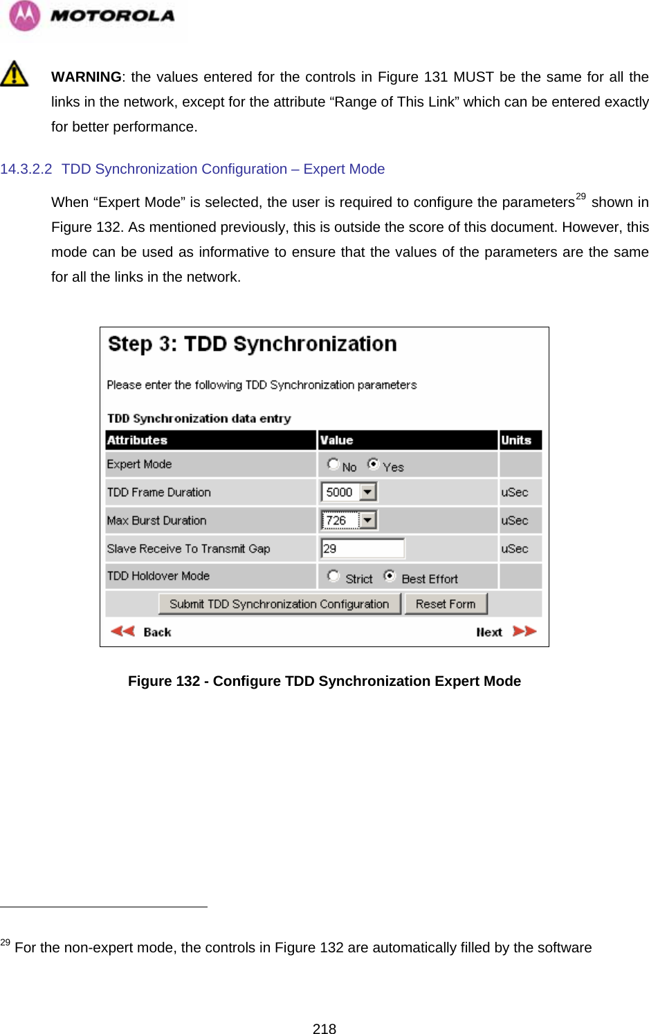
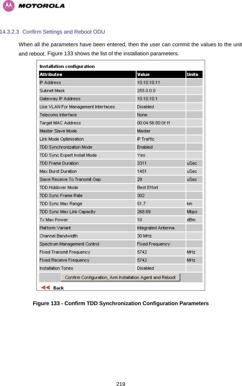
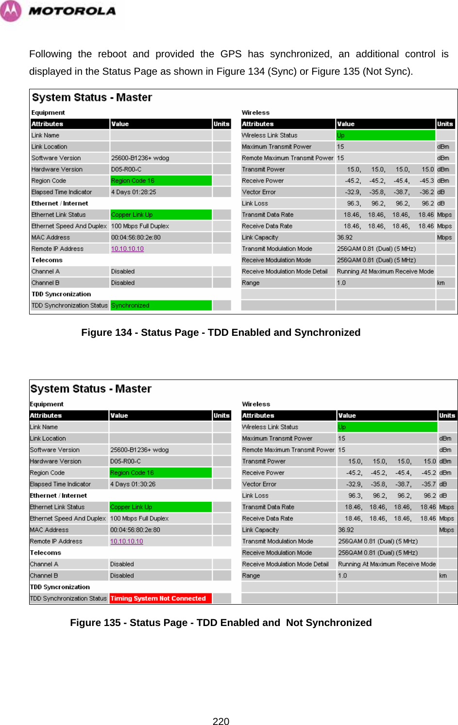
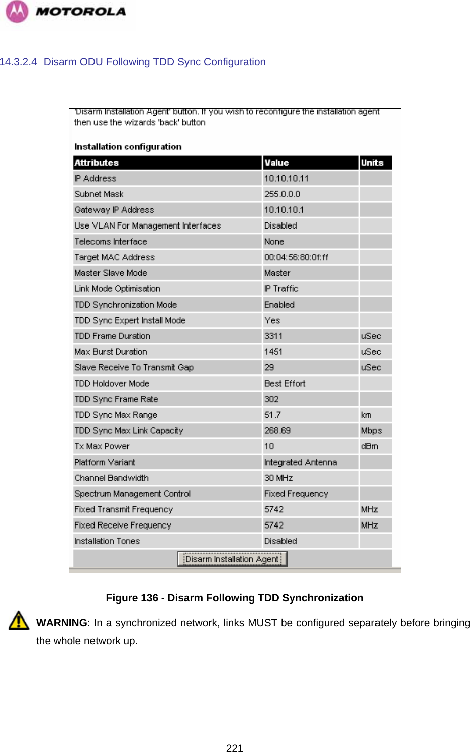
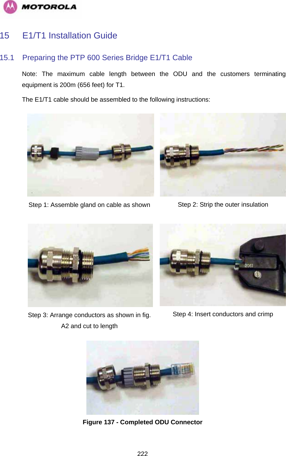
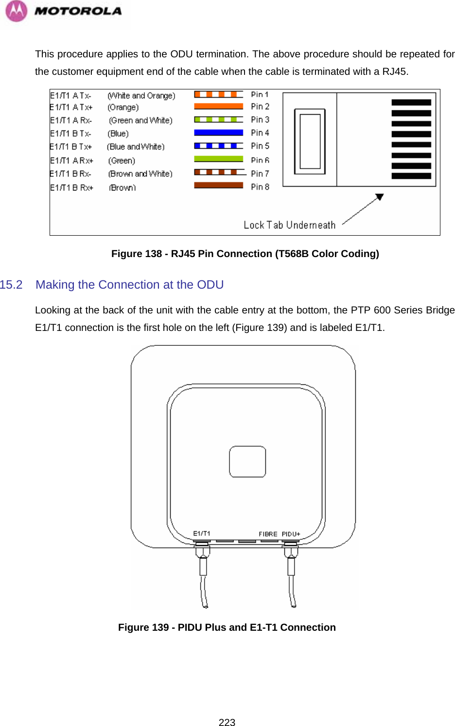
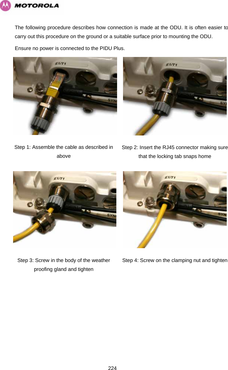
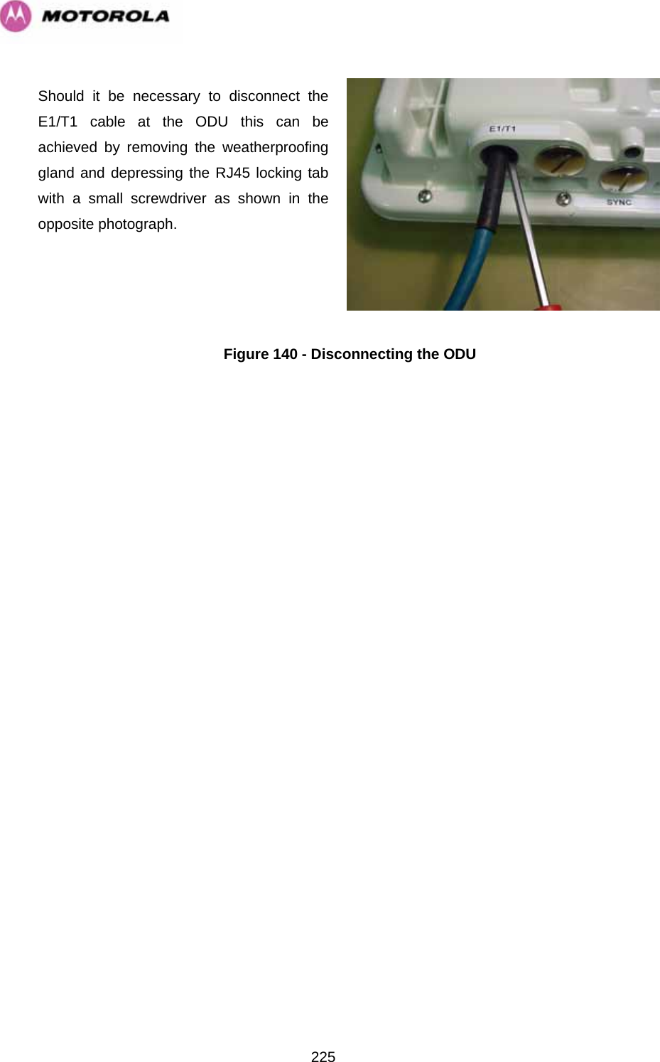
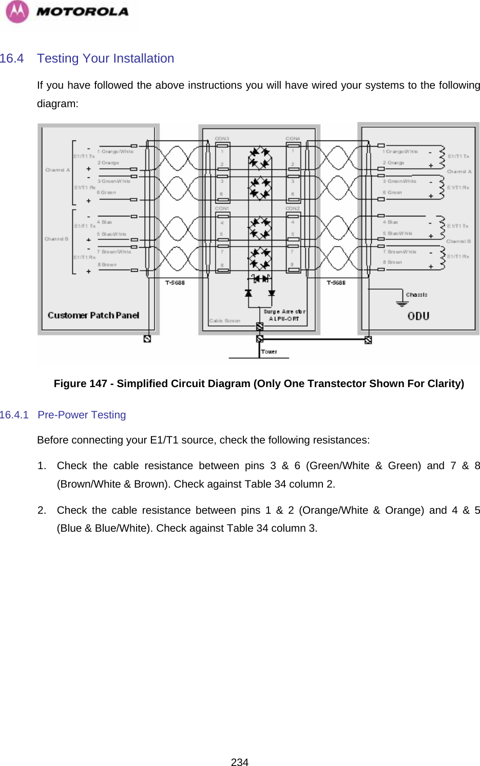
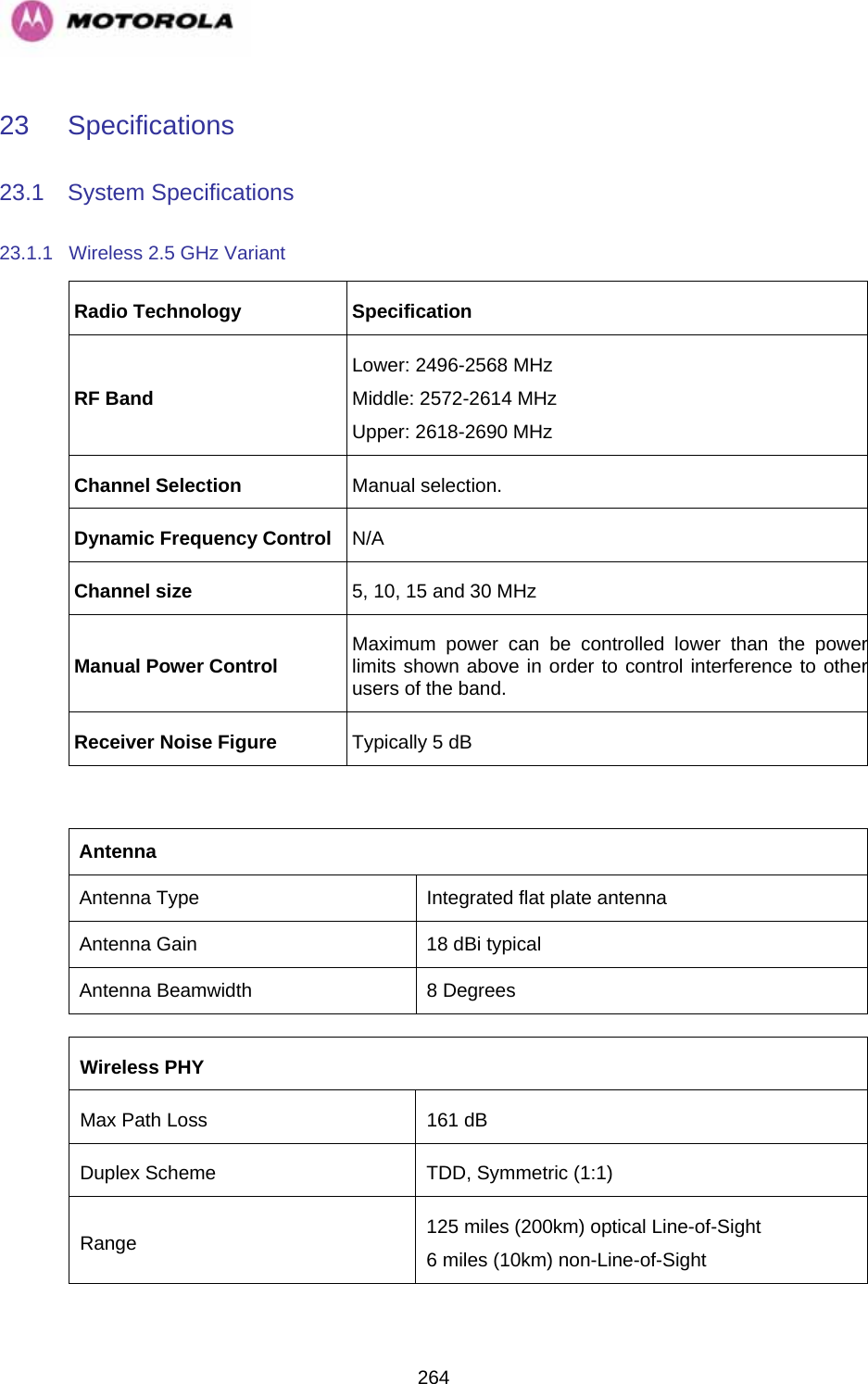
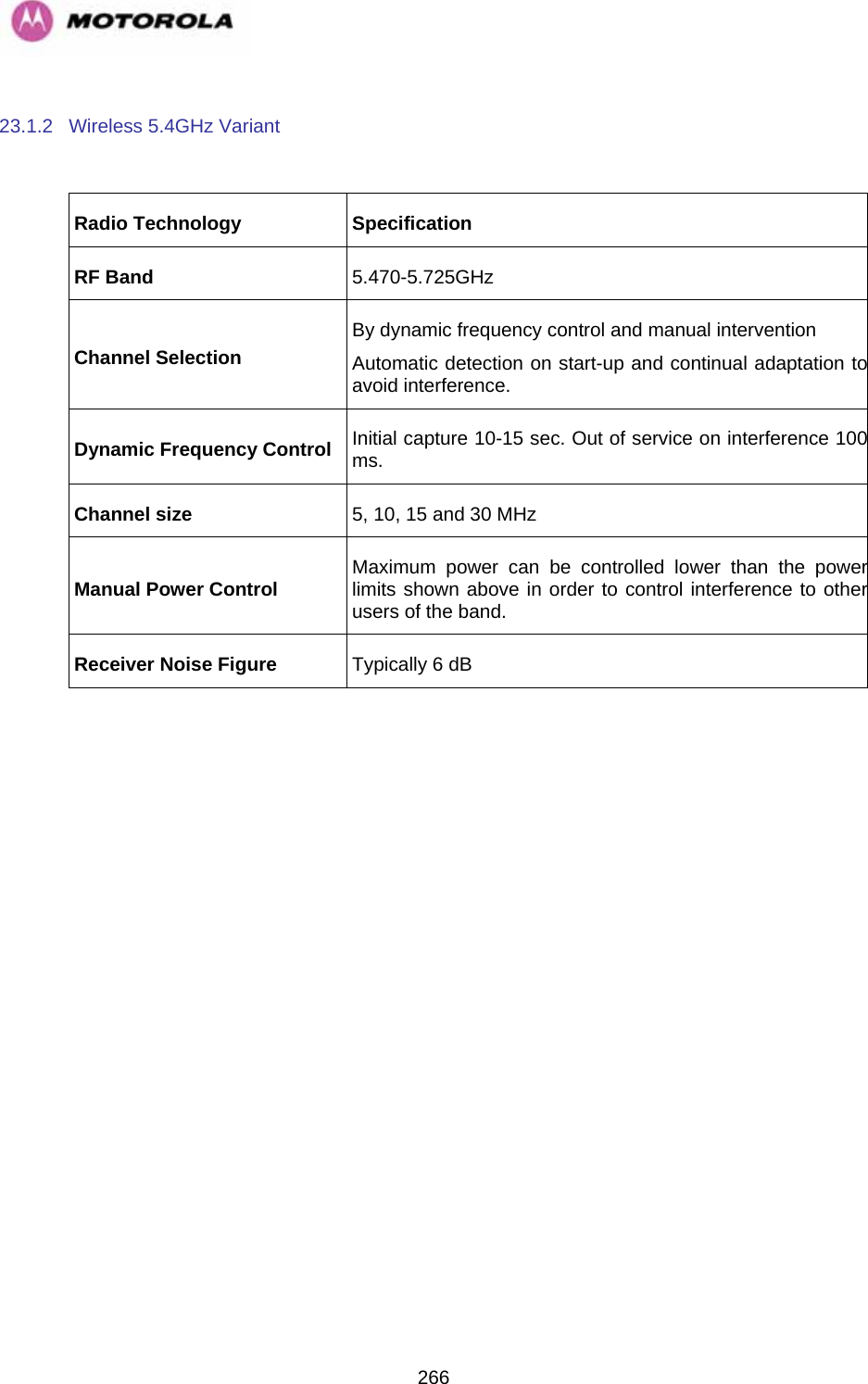
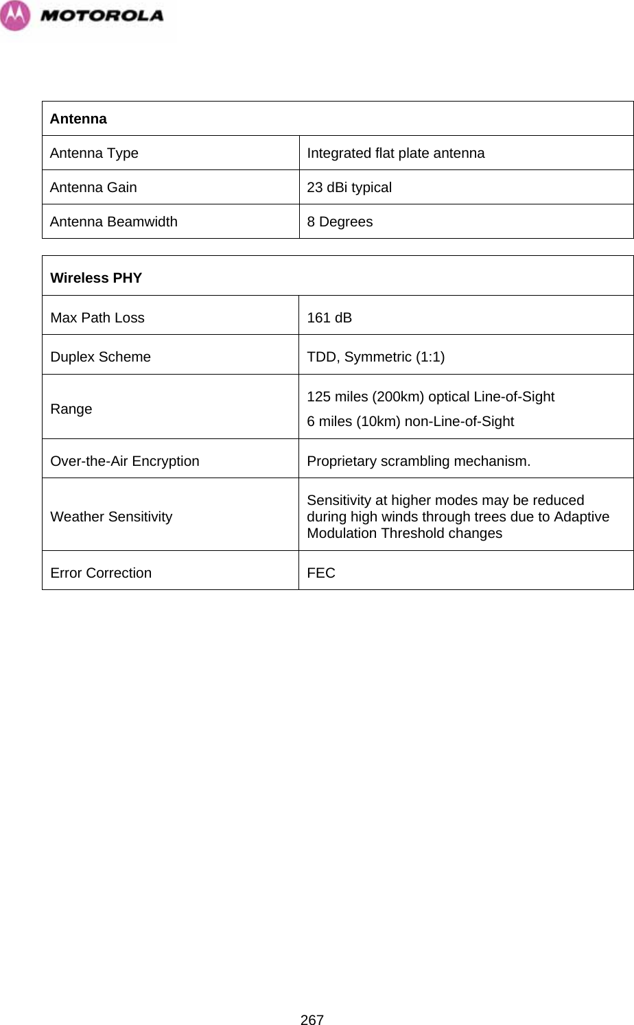
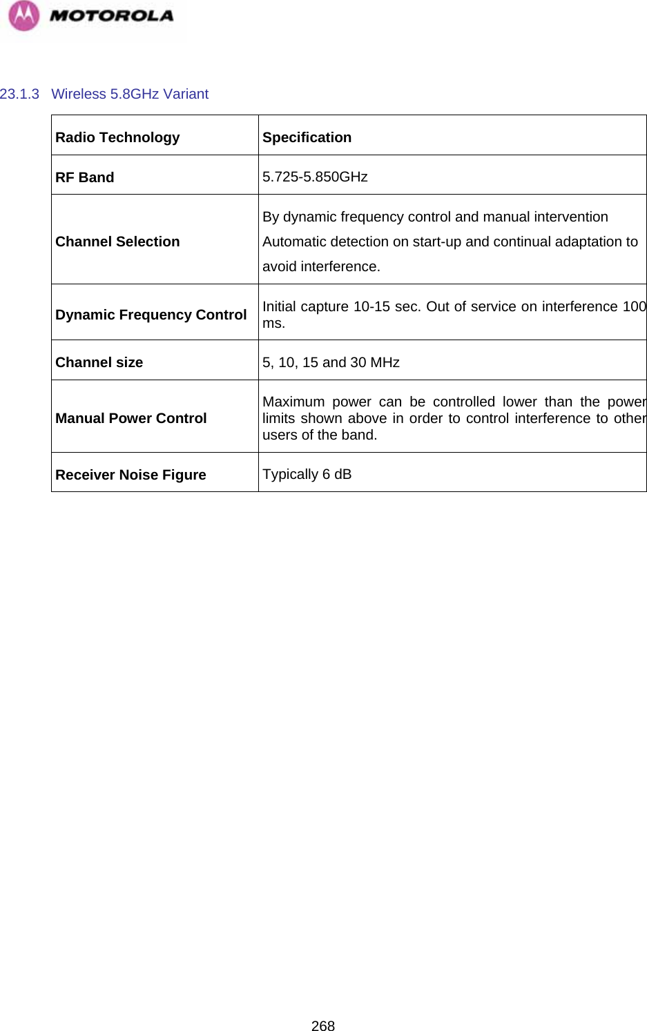
User Manual Part 2