Cambium Networks 54100 Fixed Point to Point Wireless Bridge User Manual PTP 400 Series User Guide
Cambium Networks Limited Fixed Point to Point Wireless Bridge PTP 400 Series User Guide
Contents
- 1. User Manual Revised
- 2. User Manual Part 1
- 3. User Manual Part 2
- 4. Manual 1
- 5. Manual 2
User Manual Part 2
146
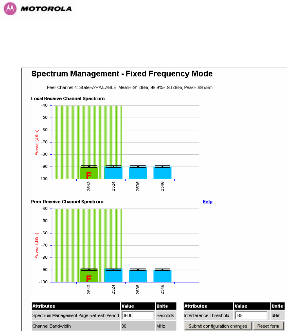
8.3.8 Spectrum Management (Fixed Frequency and WIMAX)
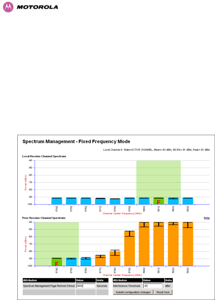
The PTP 600 Series Bridge software allows a user to optionally fix transmit and receive
frequencies for a wireless link. Once configured, the spectrum management software will not
attempt to move the wireless link to a channel with lower co and adjacent channel
interference. Therefore this mode of operation is only recommended for deployments where
the installer has a good understanding the prevailing interference environment. (See Section
8.3.4.4). Care must also be taken to ensure that the frequency allocations at each end of the
link are compatible. To help the user when identifying the mode of operation Spectrum
Management uses two visual cues. See Figure 78. The main page title identifies the mode of
operation using the “Fixed Frequency Mode” postfix and the selected channels are identified
by a red capital ‘F’.
Figure 78 - Spectrum Management Fixed Frequency Screen
147
Channel barring is disabled in fixed frequency mode; it is not required as dynamic channel
hopping is prohibited in this mode.
The only controls available to the master are the Statistics Window and Interference
Threshold attributes. They will have no effect on the operation of the wireless link and will
only effect the generation of the channel spectrum graphics.
The active channel history menu is removed in this mode of operation as channel hopping is
prohibited.
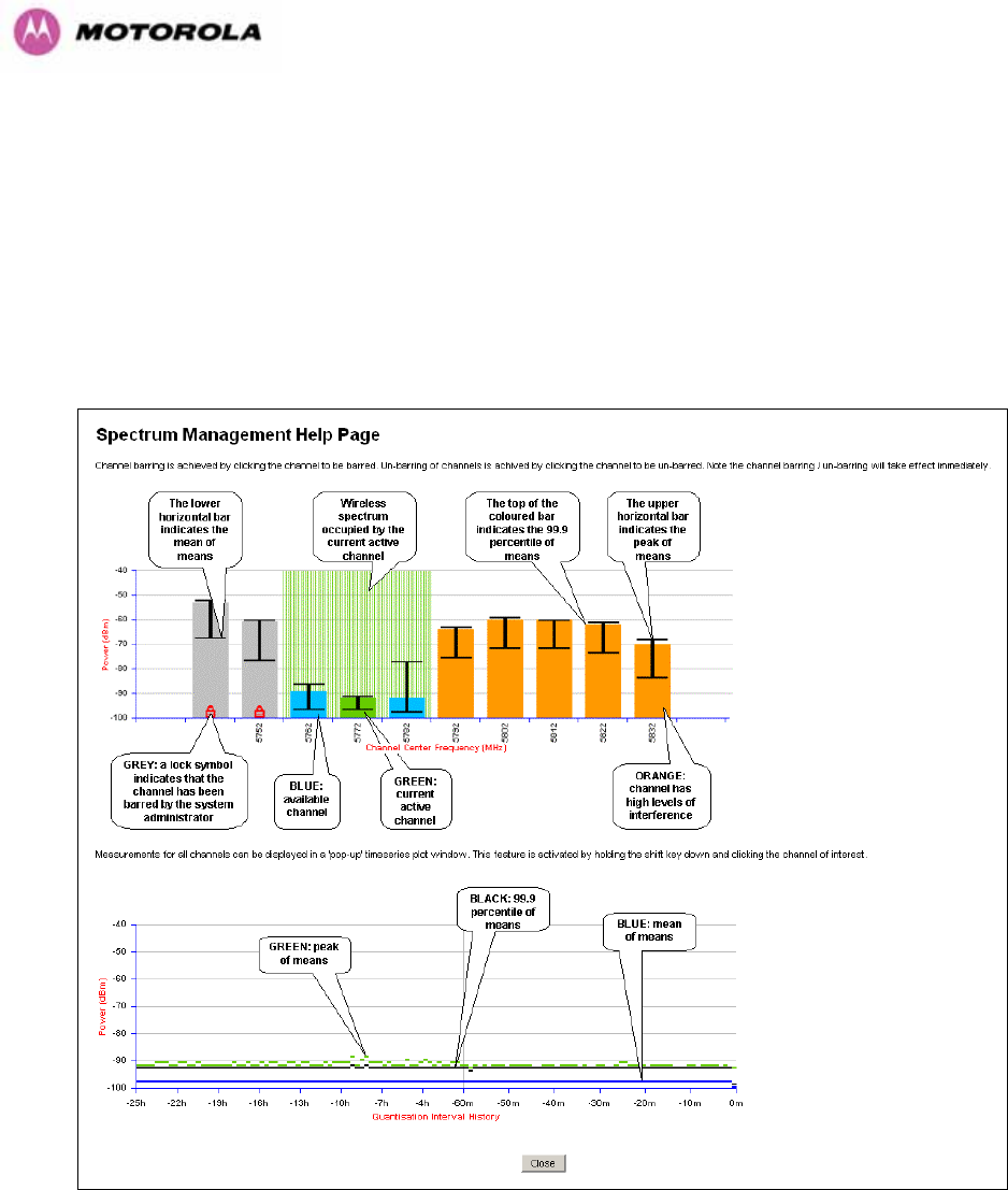
Figure 79 - Spectrum Management Help Page (Fixed Frequency)
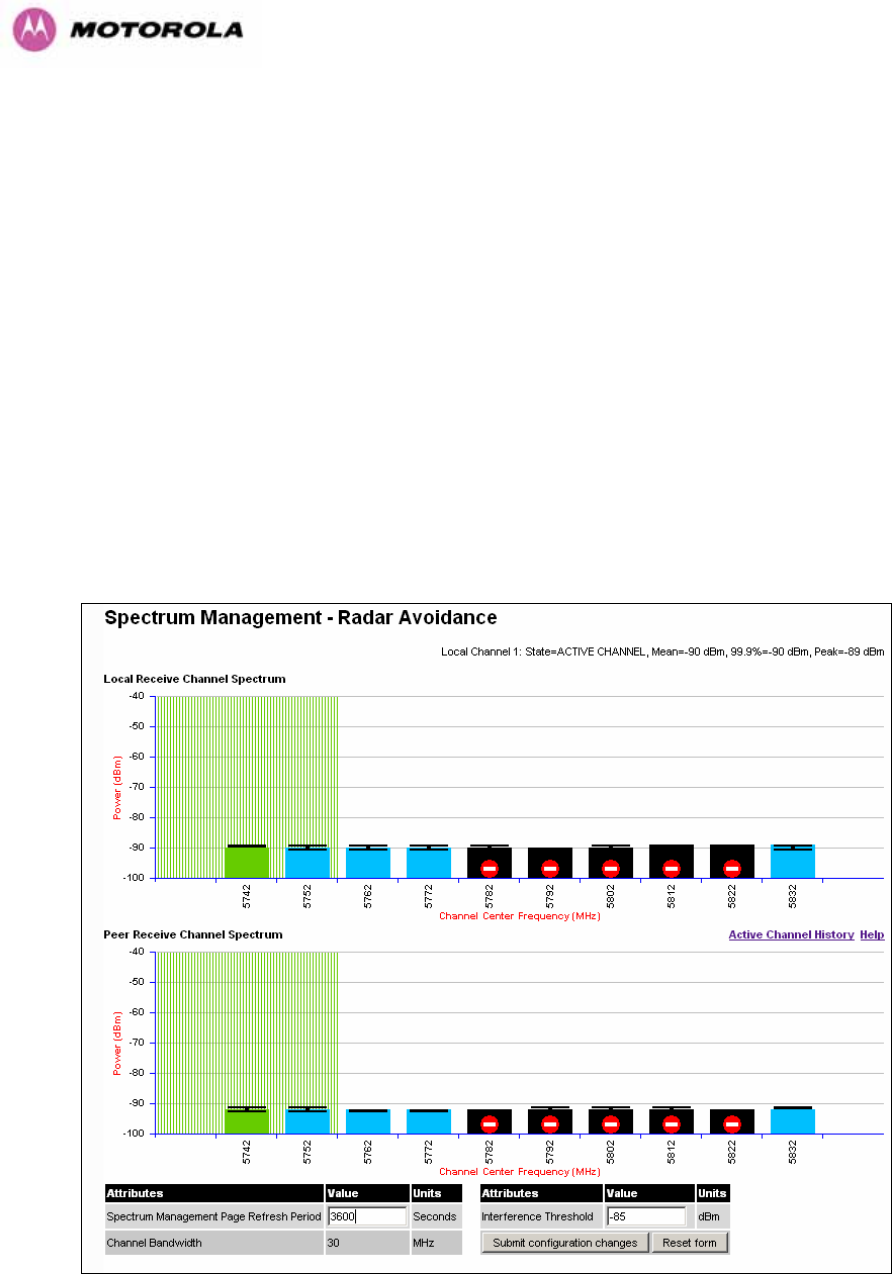
8.3.9 Spectrum Management Control - With Operational Restrictions
When operating with Radar Avoidance enabled the following variances in operation apply:
• The words “Radar Avoidance” are appended to the “Spectrum Management” title at the
top of the screen. See Figure 80 and Figure 81.
148
• The only controls available to the master are the Interference Threshold attribute. This
has no effect on the operation of the wireless link and will only affect the generation of the
channel spectrum graphics. See Figure 80.
• Extra color coding of the interference histogram is provided. See Table 20.
When operating with RTTT Avoidance enabled or other regulatory restrictions on channel
usage the following variances apply:
• All channels marked with a ‘no entry’ symbol with their associated statistics colored black
are the prohibited channels. See Figure 80 and Figure 81. These channels are never
used to host the wireless link, but CAC measurements are still taken so that adjacent
channel biases can be calculated correctly and so the user can see if other equipment is
in use.
Figure 80 - Spectrum Management Master Screen With Operational Restrictions
149
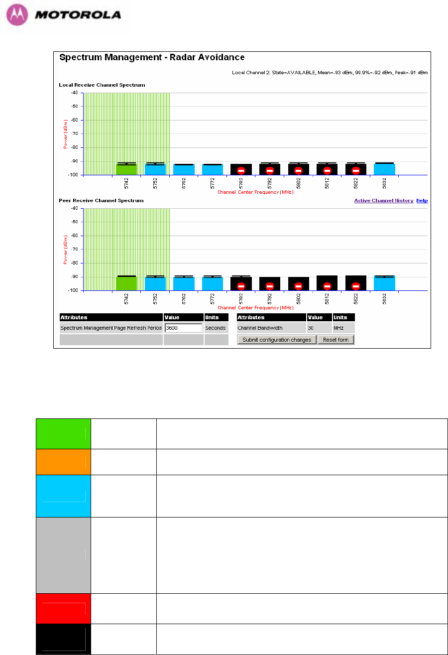
Figure 81 - Spectrum Management Slave Screen With Operational Restrictions
The colored bar represents the following channel state:
Green Active The channel is currently in use hosting the Point-to-Point
wireless link
Orange Interference The channel has interference above the interference threshold
Blue Available The channel has an interference level below the interference
threshold and is considered by the Spectrum Management
algorithm suitable for hosting the Point-to-Point link
Grey Barred
The system administrator has barred this channel from use.
Because the low signal levels encountered when a unit is
powered up in a laboratory environment prior to installation
(which makes the grey of the channel bar difficult to see). An
additional red ‘lock’ symbol is used to indicate that a channel is
barred.
Red Radar
Detected Impulsive Radar Interference has been detected on this
channel.
Region
Bar Region Bar This channel has been barred from use by the local region
regulator
Table 20 - Spectrum Management Change State Key With Operational Restrictions

152
8.3.11.1 SNMP (Simple Network Management Protocol)
The industry standard remote management technique is SNMP (Simple Network
Management Protocol). The PTP 600 Series Bridge supports version 1 and version 2c of the
SNMP protocol.
8.3.11.2 Supported Management Information Bases (MIBS)
The PTP 600 Series Bridge SNMP stack currently supports three distinct MIBs:
• MIB-II, RFC-1213, The PTP 600 Series Bridge supports the ‘System Group’ and
‘Interfaces Group’.
• Bridge MIB, RFC-1493, The PTP 600 Series Bridge supports the ‘dot1dBase Group’ and
the ‘dot1dBasePortTable Group’.
• PTP 600 Series Bridge proprietary MIB
• RFC-2233 (High capacity counter) MIB
• WiMAX MIB
SNMP TRAPs supported:
• Cold Start
• Link Up
• Link Down
• DFS Channel Change
• DFS Impulsive Interference
153
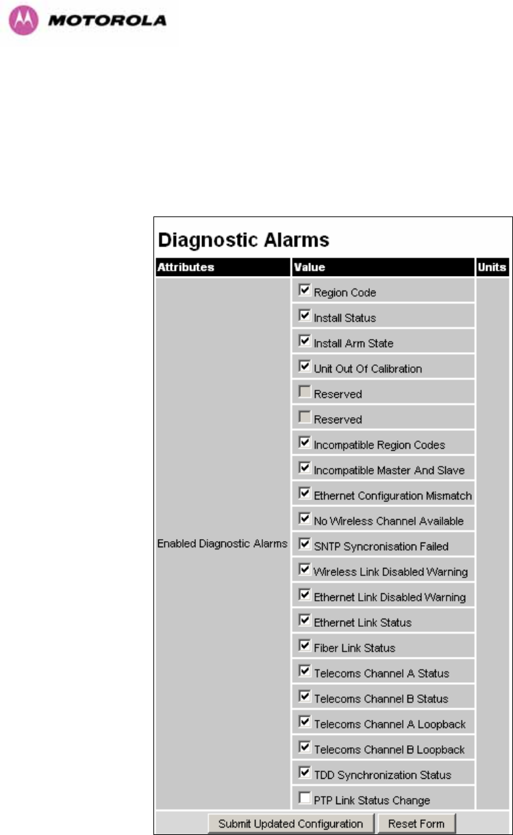
8.3.11.3 Diagnostics Alarms
A number of diagnostics alarms have been added to allow SNMP agents to receive traps and
emails if required. Refer to Section 8.1.1 for a description of all these alarms. Checking the
control “Enabled Diagnostic Alarms” in SNMP and/or SNTP selects all the alarms shown in
Figure 84. Users can access the sub-menu “Diagnostic Alarms” to modify the alarms
selected.
Figure 84 - Remote Management - Diagnostic Alarms
For a copy of the Motorola proprietary version 1 and version 2 MIB RFCs please consult the
installation CD

154
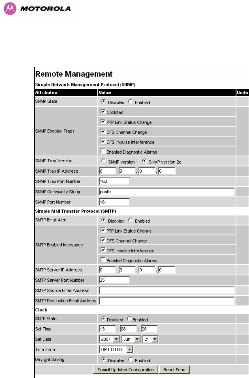
8.3.11.4 SNMP Configuration
SNMP State: The SNMP state attribute controls the creation of the SNMP features. Changing
the SNMP state attribute requires a mandatory reboot of the unit. Only when the SNMP state
is enabled at system start-up will the SNMP processor task be created.
SNMP Enabled Traps: The SNMP Enabled Traps attribute controls which SNMP Traps the
unit will send.
SNMP Community String: The SNMP community string acts like a password between the
networks SNMP management entity and the distributed SNMP clients (600 Series bridge).
Only if the community string is configured correctly on all SNMP entities can the flow of
management information take place. By convention the default value is set to ‘public’. When
the community string is changed the system requires a mandatory reboot before the new
string or phrase is adopted.
SNMP Port Number: Is the port the SNMP management agent is listening to for commands
from an SNMP manager. The default value for this port number is 161.
SNMP Trap IP Address: Is the address of either the network SNMP manager or Trap
receiver. When asynchronous events (traps in SNMP terminology) are generated, the client
unicasts these to this IP Address. When the address is changed the system requires a
mandatory reboot before the setting is adopted
SNMP Trap Port Number: The SNMP Trap Port Number is the port number of either the
networked SNMP manager or Trap receiver. By convention the default value for the port
number is 162. When the port number is changed the system requires a mandatory reboot
before the setting is adopted.
WiMAX Control: Enables and Disables the WiMAX (802.16) MIB. This control is only
displayed when ‘Fixed Frequency’ is selected during installation.
8.3.11.5 SMTP (Simple Mail Transport Protocol)
The SMTP client is an alternative method for the 600 Series bridge to alert a system
administrator when there are or have been system errors
SMTP Email Alert: This attribute controls the activation of the SMTP client.
SMTP Enabled Messages: The SMTP Enabled Messages attribute controls which email
alerts the unit will send.
SMTP IP Address: The IP address of the networked SMTP server.

155
SMTP Port Number: The SMTP Port Number is the port number used by the networked
SMTP server. By convention the default value for the port number is 25.
SMTP Source Email Address: The email address used by the 600 Series bridge to log into
the SMTP server with. This must be a valid email address that will be accepted by your
SMTP Server
SMTP Destination Email Address: The email address to which the 600 Series bridge will
send the alert messages.
8.3.11.6 SNTP (Simple Network Time Protocol)
The SNTP client allows the 600 Series bridge to obtain accurate date and time updates from
a networked timeserver. The system time is used for SNMP and event logging.
SNTP State: When enabled, the Remote Management web page permits the following
attributes to be set:
SNTP IP Address: The IP address of the networked SNTP server.
SNTP Port Number: The port number of the networked SNTP server. By convention the
default value for the port number is 123.
SNTP Poll Interval: The period at which the SNTP client polls the server for time correction
updates. Default 1 hour. If for any reason an SNTP poll fails, the client will automatically
perform 3 retries before waiting for the user defined poll period.
Time Zone: The time zone is a fixed offset from GMT that is added to the SNTP time to allow
the expression of time in all geographic time zones.
Daylight Saving: Allows a fixed offset of one hour to be added to the SNTP time in order to
reflect the local daylight saving time.
8.3.11.7 Setting the clock
The PTP 600 Series bridge has a system clock which can be used to supply accurate date
and time information in the absence of a SNTP server. The system clock is battery backed
and will continue to operate for several days if the 600 Series bridge has been switched off.
SNTP State: If the SNTP State is set to “Disabled”, see Figure 83, then the Remote
Management web page allows the following attributes to be set:
Set Time: Shows the current time in 24 hour mode. The three editable fields display hours
minutes and seconds.

156
Set Date: Displays the current date. The year, month and day can be set using the drop-
down selection boxes.
Time Zone: See Section 8.3.11.7.
Daylight Saving: See Section 8.3.11.7.
8.3.12 Diagnostics
To further enhance the diagnostic capabilities of the PTP 600 Series, the storage of link
performance histograms has been extended to 31. To optimize RAM (volatile memory) usage
a cascading histogram approach has been adopted. The root histogram is identical to the
histograms in 58100 that is data is stored for one hour at a resolution of one second. In 58100
the histograms were simple cyclic buffers which never stored more that the last one hour of
data. The new cascading histogram approach daisy chains multiple histograms together.
When the first histogram fills up the overflow from the first is used as an input to the next
histogram in line. To optimize memory utilization a statistical analysis is performed on the
overflow to reduce the amount of data to be stored. In the case of the PTP 600 Series the
cascading histograms are defined as:
• Histogram 1: 1 hour at a resolution of 1 second
• Histogram 2: 24 hours at a resolution of 1 minute
• Histogram 3: 30 Days at a resolution of 1 hour
For example, when histogram 1 fills up and starts to overflow the first minute of overflow is
analyzed and the maximum, minimum and mean over that minute are computed and inserted
into histogram 2. When histogram 2 fills up and starts to overflow the first hour of overflow is
analyzed and the maximum, minimum and mean over that hour is computed and inserted into
histogram 3. When histogram 3 starts to overflow, the overflow data is simply discarded.
157
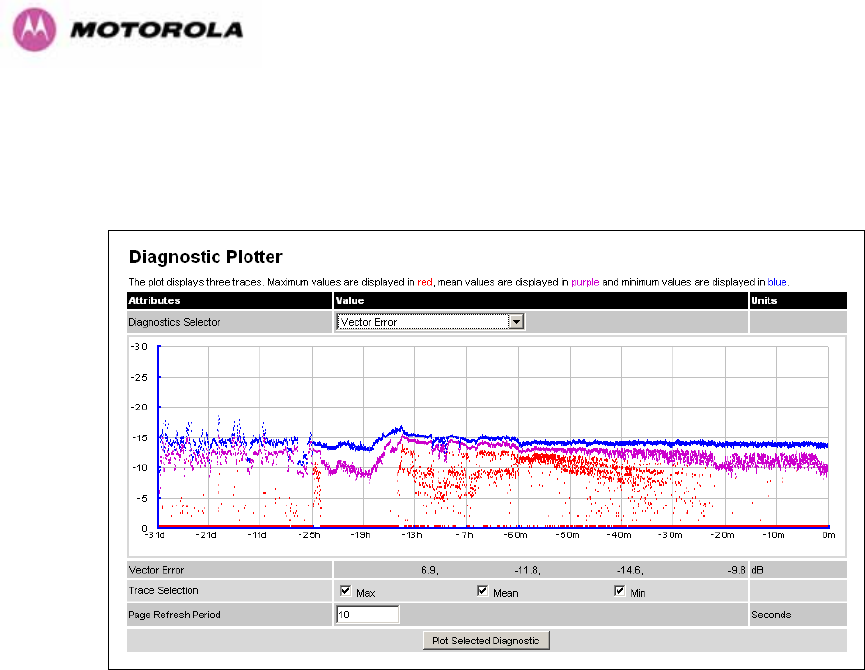
8.3.12.1 Diagnostic Plotter
New for the PTP 600 Series is the system administration diagnostic plotter facility see Figure
85.
Figure 85 - Diagnostic Plotter
The diagnostic plotter allows the system administrator to view the cascading histogram data
in an easily accessible graphical form. The plot always displays three traces, maximum,
minimum and mean by default. The diagnostic selector allows the user to select the various
categories of histogram.
The histograms that are available are:
• Vector Error
• Rx Power
• Tx Power
• Signal Strength Ratio
• Link Loss
• Rx Data Rate
• Tx Data Rate
• Aggregate Data Rate
The diagnostic plotter uses a novel time representation in the x-axis which compresses the
timeline of the plot without sacrificing resolution.

158
The trace selection allows the user to control which traces are plotted.
As with other management pages the page refresh period can be used to interactively monitor the
wireless link.
8.3.12.2 Diagnostics Download
The diagnostics Download page allows the system administrator to download snapshots of
system diagnostics.
Figure 86 - CSV Download
The following diagnostics are available:
• Vector Error
• Rx Power
• Tx Power
• Signal Strength Ratio V/H
• Link Loss
• Rx Data Rate
• Tx Data Rate
• Aggregate Data Rate
• Receive SNR
• Rx Gain
All diagnostics are extracted from the associated status and statistics web page histograms.
They are translated in a CSV file containing at most 578424 entries.
24 5784 entries comprises 3600 entries for the first hour, 1440 entries for the next 24 hours and 744 entries for the next 31
days.
159
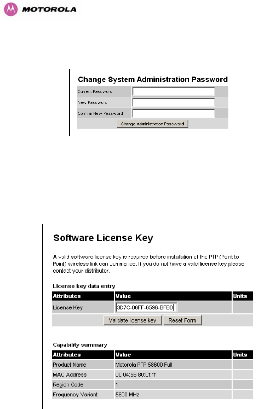
8.3.13 Change System Administration Password
This page (Figure 87) is used to change the password for the system administration (The
factory default is blank).
Figure 87 - Password Change
To change the password any combination of alphanumeric characters, up to 31 characters in
length, can be used.
8.3.14 License Key
The License Key data entry page allows the system administrator to update the 600 Series
bridge license key. Figure 88 shows a sample license key data entry page.
Figure 88 - Software License Key Data Entry
160
The user must enter the license key and click the ‘Validate License Key’ button to check that
the key is valid and program it to non-volatile memory.
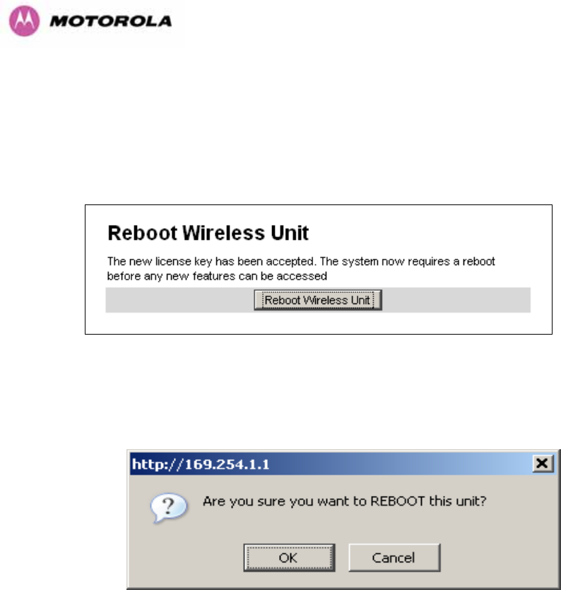
If a valid license key is detected then the user will be presented by a system reboot screen.
Figure 89: License Key reboot Screen
The user will then be asked to confirm the reboot (Figure 90).
Figure 90 - Reboot Confirmation Pop Up
161
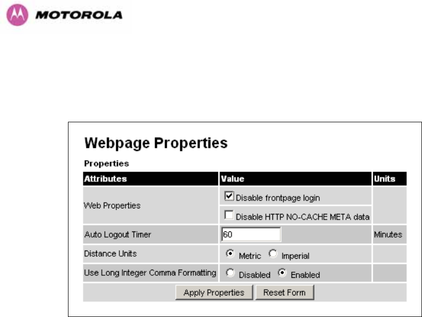
8.3.15 Properties
The web page properties screen allows the user to configure the web page interface.
Figure 91 – Properties
WEB Properties: Disable Front Page Login Allows access to homepage and status page
web pages without forcing a login as the system administrator.
WEB Properties: Disable HP NO-CACHE META data: Removes the HTTP NO-CACHE
META clause from all dynamically created web pages.
Auto Logout Timer Configures the time, in minutes, when the system administrator is
automatically logged out if no web page activity is detected.
Distance Units Swaps the default metric display of distance in to imperial units, for example
km to Miles.
Use Long Integer Comma Formatting Changes the format of long integers from 1000000 to
1,000,000.
162
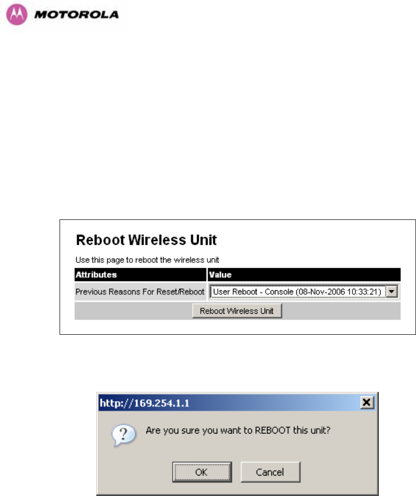
8.3.16 Reboot
The reboot page allows the system administrator to perform commanded reboots of the
wireless unit. The reboot page also allows the system administrator to view a list of past
reboot reasons. The “Previous Reasons For Reset/Reboot” field has been implemented as a
drop down selection box, where the latest reason for reboot is located at the top of the list.
If the SNTP service from the remote management section above is active, or the system time
has been set, then the command reboot reason will be accompanied by the date and time at
which the reboot occurred.
Figure 92 - System Reboot
Figure 93 - Reboot Confirmation Pop Up

163
9 Recovery Mode
The Motorola PTP 600 point-to-point wireless Ethernet bridges have a special mode of
operation that allows the user to recover a unit from configuration errors or software image
corruption.
Recovery mode is entered by depressing the Recovery Switch located on the underside of
the PIDU Plus while applying mains power, as shown in Section 3.3.2. The Recovery Switch
should be held in the depressed state for between 10 and 20 seconds after the application of
mains power. The Ethernet LED will flash with 10 double flashes at power up.
When in recovery mode the user will be able to access the unit via the Ethernet interface. The
Ethernet interface will have its IP address set to 169.254.1.1 (or 10.10.10.10). On connection
to a unit in recovery mode the following screen is displayed (Figure 94):
Figure 94 - Recovery Mode Warning Page
164
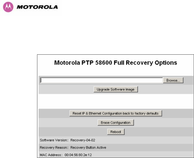
Clicking on the warning page image will take the user on to the Recovery Option Page
(Figure 95).
Figure 95 - Recovery Options Page
The recovery options available are:
Upgrade Software Image: This allows the user to reload a software image. This may be the
original image if software corruption is suspected or a step back to an old image if an
incorrect image has just been loaded.
Reset IP & Ethernet Configuration back to factory defaults: This allows the user to reset
the unit back to the factory defaults:
o IP Address 169.254.1.1 (or 10.10.10.10)
o Netmask 255.255.0.0
o Gateway 169.254.1.0
o Ethernet Interface Auto-negotiate, Auto-MDI/MDIX
Erase Configuration: This allows the user to erase the unit’s entire configuration. Executing
this option will also erase factory settings such as target MAC address, range setting, license
key, etc.
Reboot: This allows the user to reboot the unit. This option must be executed after resetting
the IP & Ethernet configuration or erasing the configuration detailed above.
165
Software Version: This is the software version of the recovery operating system permanently
installed during manufacture.
Recovery Reason: Indicates the reason the unit is operating in Recovery mode. Possible
reasons are “Recovery button active” or “Invalid or corrupt image”
MAC Address: The MAC address shown here is the MAC address of the unit programmed
during manufacture.
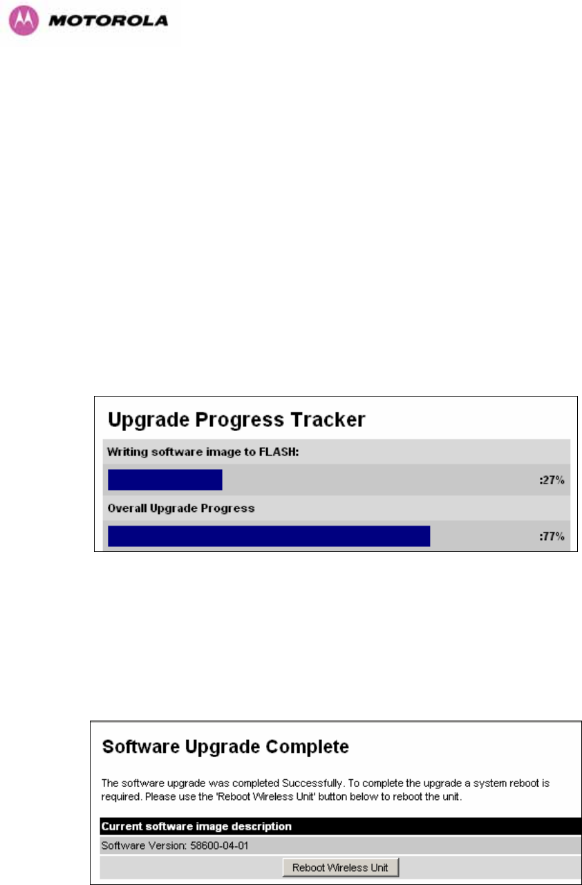
9.1 Upgrade Software Image
The first step (Figure 95) is to use the ‘Browse’ button to locate the software image to be
downloaded. Once located the user should press the “Upgrade Software Image” button to
start the software download process.
During software download, progress is indicated by a pair of progress bars (Figure 96).
Figure 96 - Software Download Progress Indicator Page
When the download is complete a page is displayed indicating the status of the software
download (Figure 97).
Figure 97 - Software Download Complete Page
166
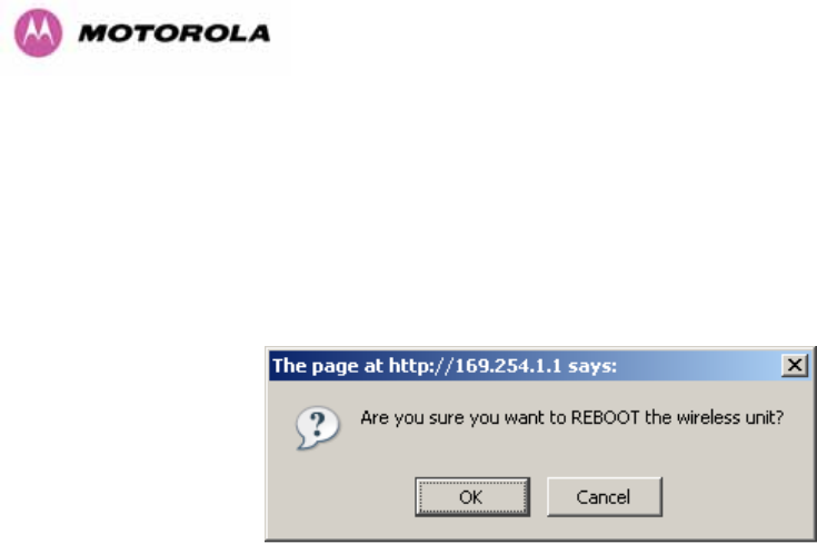
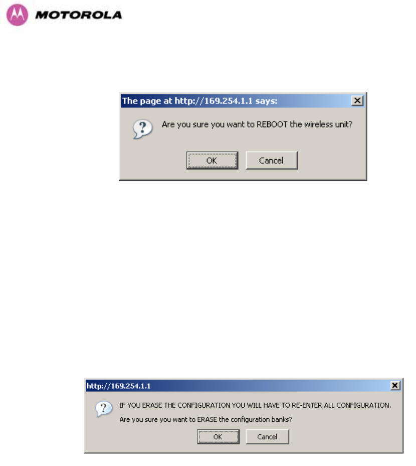
After carefully checking that correct image has been downloaded the user should reboot the
unit by pressing the “Reboot Wireless Unit” button. The user will then be presented with a pop
up box asking them to confirm the action (Figure 98)
Figure 98 - Reboot Confirmation Pop Up
The unit will now reboot. Providing the unit configuration is still intact the unit should restart in
normal operational mode and the link should recover. Should the unit or link fail to recover the
user should refer to Section 10.
167
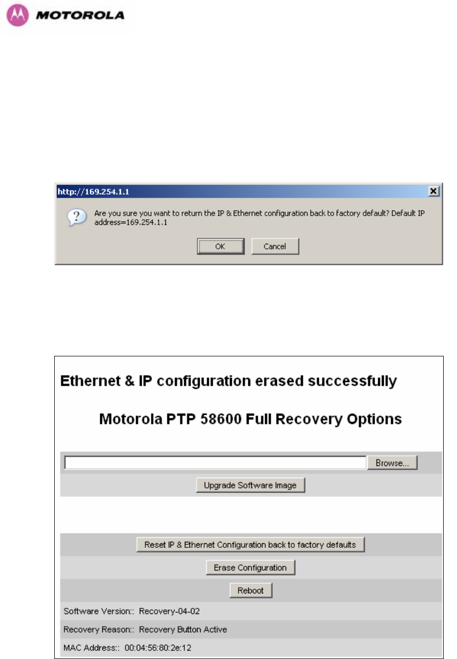
9.2 Reset IP & Ethernet Configuration
To reset IP & Ethernet configuration back to factory defaults the user should press the “Reset
IP & Ethernet Configuration back to factory defaults” button on the “Recovery Options” page
(Figure 95). The user will now be presented with a pop up box asking them to confirm the
action (Figure 99).
Figure 99 - Confirm Reset to Factory Default Pop Up
On confirmation the following page will be displayed (Figure 100). The user should now
reboot the unit by pressing the “Reboot” button.
Figure 100 - IP and Ethernet Erased Successfully page
168
The user will now be presented with a pop up box asking them to confirm the action (Figure
101)
Figure 101 - Reboot Confirmation Pop Up
The unit will now reboot. The unit should now start up in normal mode but with the IP address
set to 169.254.1.1 and the Ethernet interface set to auto-negotiate and auto-MDI/MDIX.
Should the unit fail to start up the user should refer to Section 10.
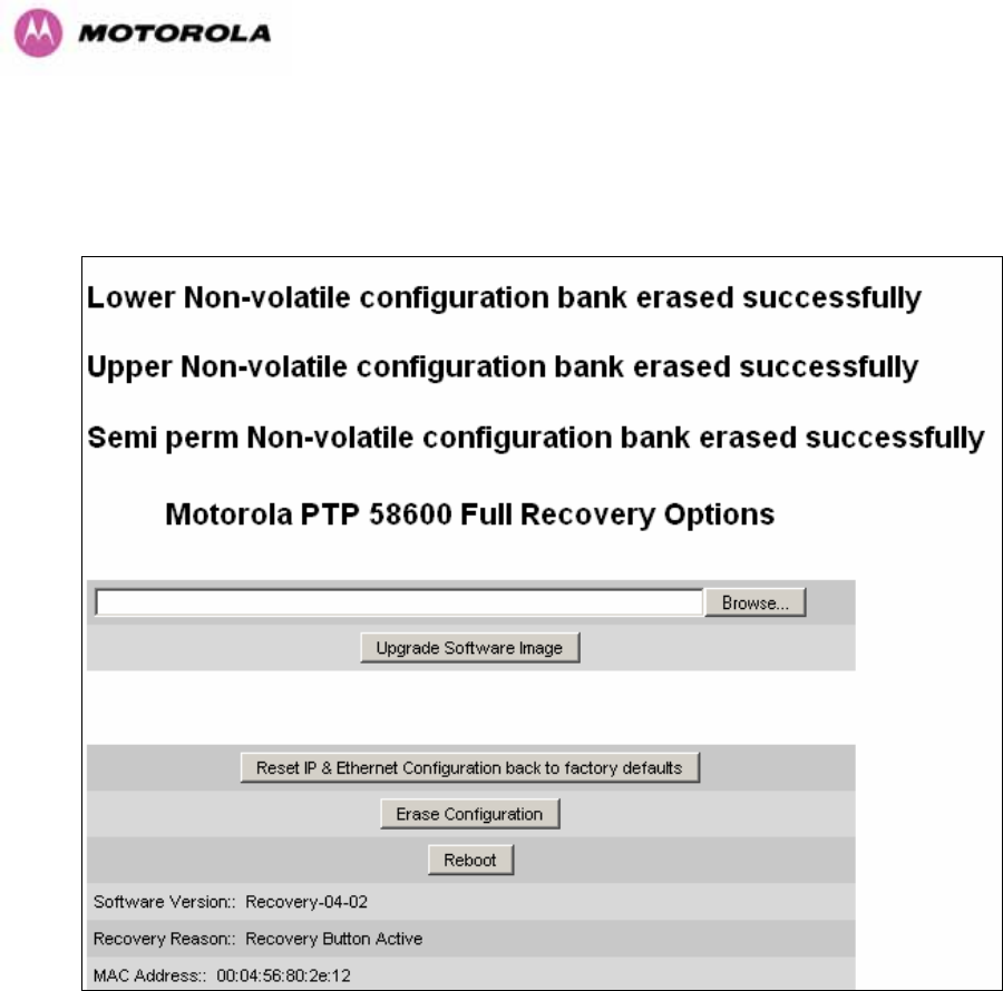
9.3 Erase Configuration
To erase the unit’s configuration the user should press the “Erase Configuration” button on
the “Recovery Options” page (Figure 95). The user will now be presented with a pop up box
asking them to confirm the action (Figure 102).
Figure 102 - Confirm Erase Configuration Pop Up
170
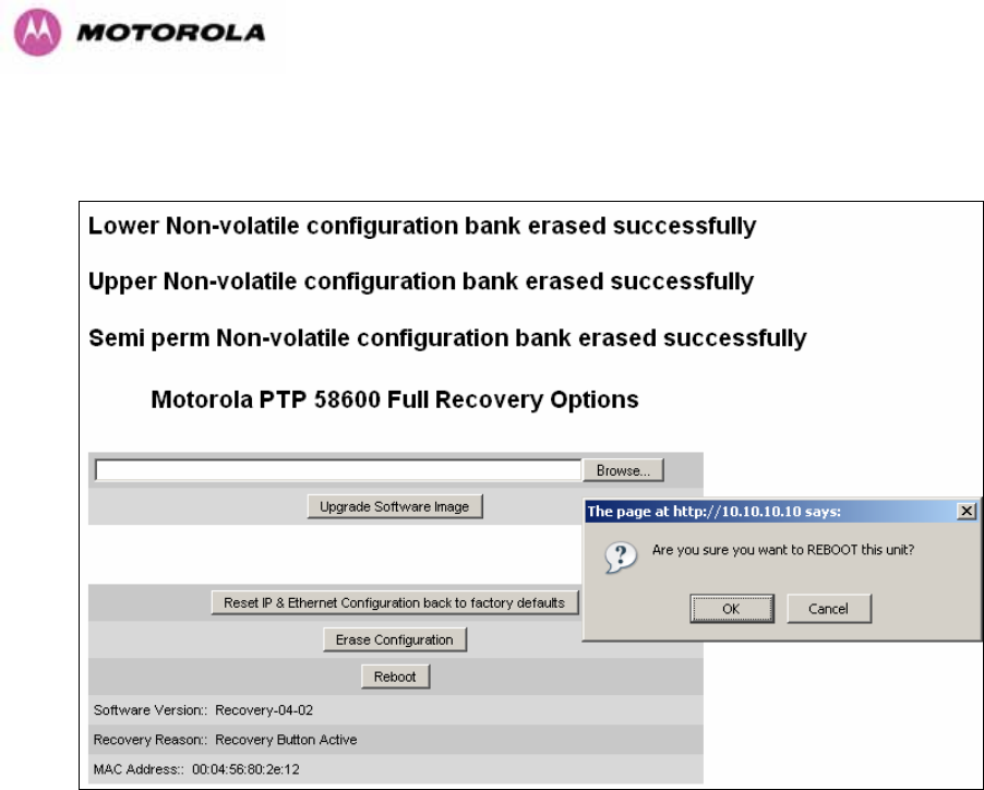
The user will now be presented with a pop up box asking them to confirm the action (Figure
104)
Figure 104 – Erase Configuration - Reboot Confirmation Pop Up
The unit will now reboot. The unit should now start up in normal mode but with all
configuration erased. Should the unit fail to start up the user should refer to Section 10.
171
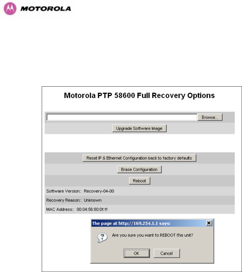
9.4 Reboot
To erase the unit’s configuration the user should press the “Reboot” button on the “Recovery
Options” page (Figure 95). The user will now be presented with a pop up box asking them to
confirm the action (Figure 105).
Figure 105 – Recovery - Reboot Confirmation Pop Up
The unit will now reboot. The unit should now start up in normal operational mode. Should the
unit fail to start up the user should refer to Section 10.
172
10 Fault Finding
If communication has been lost with the unit at the near end of the link then there may be a
hardware fault with the wiring, network or hardware. Go to the hardware section below. If
communication with the far end of the link is lost then go to the radio section below.
10.1 Hardware
If there are problems suspected with the link hardware the following procedure is
recommended.
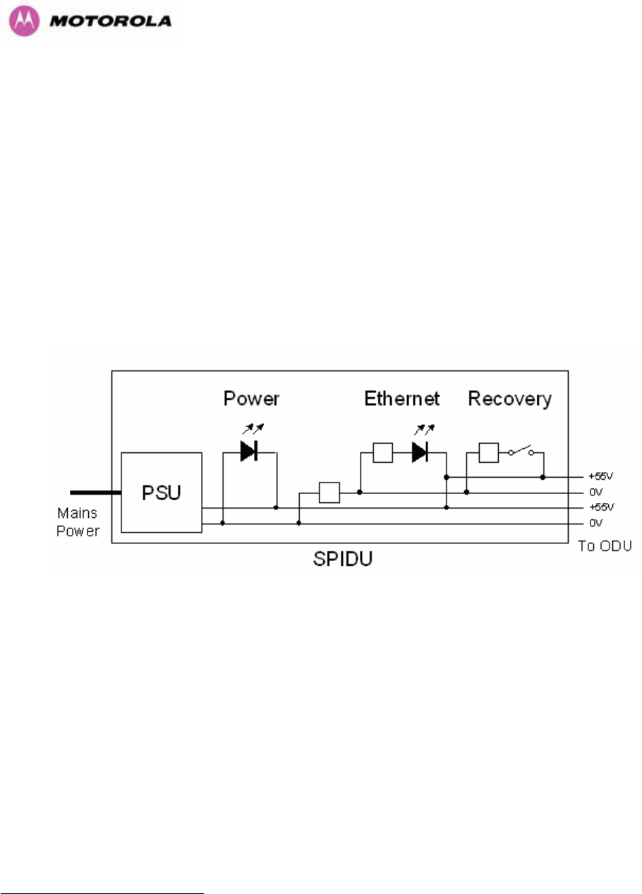
The following diagram illustrates the main system connections:
Figure 106 - Main System Connections
10.1.1 Power
Check the power LED at each end of the link. If the power lights are illuminated go to the
Ethernet section below. If at either end they are not illuminated then25 check the Ethernet
LED.
If neither is illuminated then there is no voltage on the power wires to the ODU.
• Check that the mains power is connected and switched on.
• Check that the lamp illuminates if the ODU connector is disconnected at the PIDU Plus
(Remove the PIDU Plus cover).
25 The power indicator LED should be continually illuminated.

173
If it does illuminate then either the ODU is drawing too much current, or the power wiring to
the ODU is short circuit or the PSU is supplying insufficient power. The likely fault can be
determined by removing the jumper (J906), found inside the removable cover of the PIDU
Plus, and measuring the current taken with an ammeter placed across the 2 jumper pins. This
is normally 10mA without the ODU connected and 300mA to 1A when the ODU is connected.
If it does not illuminate then recheck that power is applied to the PIDU Plus by measuring the
voltage across +55V and 0V pads inside the removable cover in the PIDU Plus. Check that
the PIDU Plus is not short circuit by measuring the impedance across the Power connector. Is
the lamp faulty?
10.1.2 Ethernet
The Ethernet LED is driven from the ODU processor and thus is capable of informing you of
many conditions using different flash sequences. If the Ethernet indicator does not illuminate
at all there are four possible conditions.
• There is no power reaching the ODU because of a wiring fault
• The ODU is faulty
• The PIDU Plus is faulty
• The Ethernet network side is faulty
Look at the following table to check the LED response for power up, disconnect the power
and reapply and note what happens.
Differentiating between 1-3 and 4 can be achieved by removing the power for 1 second.
Watch the Ethernet indicator for 1 minute, if it never flashes then the problem is 1-3. Take the
jumper (J906) out of the PIDU Plus and check the current taken by the ODU. This should be
300mA to 1A when starting to run normally.
If the Ethernet indicator flashes to begin with but then stops flashing, the ODU is powered and
software loaded but Ethernet connectivity has been lost between the ODU and the users
connected equipment. All Ethernet connections should be rechecked.

174
Power Indoor Unit LED check chart:
Mode Green LED
Yellow LED No Ethernet
Cable Connected
Yellow LED
Ethernet Cable
Connected between
PIDU Plus and
NIC/Switch/Hub
No Power Applied Off Off Off
Power Applied On
Will flash once per second
regularly approximately 30
seconds after power
applied for 10 seconds then
will go out and stay out
Will flash once per
second regularly
approximately 30
seconds after power
applied for 10
seconds then operate
as Ethernet
Link/Activity LED
Valid Ethernet Link
and no traffic On N/A Will be on solid for a
valid link.
Valid Ethernet Link
with traffic On N/A Will be on solid, but
will blink randomly as
traffic passes through
Recovery Switch
Pressed and held
for >10 seconds
from power on
(Recovery is
pressed while
power is applied)
On
Off while switch pressed.
Approximately 30 seconds after releasing the
switch, flashes twice per second regularly for 10
seconds, then boots in “Recovery Mode”
While in “Recovery Mode” the unit will only be
accessible via the IP address 10.10.10.10 or
169.254.1.1.
10.1.3 Checking your wiring
If the above procedures fail to diagnose the issue you may have a wiring fault. Unplug the
RJ45 from the PIDU+ and check the following resistances at the RJ45:
1. Check the cable resistance between pins 1 & 2, 3 & 6, 4 & 5 and 7 & 8 at the RJ45.
Check against column 2 in Table 21. Resistances for each pair should be within 1 ohm of
each other.
2. Check the cable resistance between pins 1 & 3 at the RJ45. Check against column 3 in
Table 21.
3. Check the cable resistance between pins 4 & 7 at the RJ45. Check against column 4 in
Table 21.
4. Ensure that there is greater than 100K ohms between pins 1 & 8 for all cable lengths.

175
5. Ensure that there is greater than 100K ohms between pin 1 and ODU ground for all cable
lengths.
6. Ensure that there is greater than 100K ohms between pin 8 and ODU ground for all cable
lengths
CAT-5 Length
(Meters) Resistance
between pins
1 & 2, 3 & 6 , 4 & 5
and pins 7 & 8
(ohms)
Resistance
between pins
1 & 3
(ohms)
Resistance
between pins
4 & 7
(ohms)
0 0.8 1.0 1.6
10 2.5 2.7 3.3
20 4.2 4.4 5.0
30 5.9 6.1 6.7
40 7.6 7.8 8.4
50 9.3 9.5 10.1
60 11.0 11.2 11.8
70 12.7 12.9 13.5
80 14.4 14.6 15.2
90 16.1 16.3 16.9
100 17.8 18.0 18.6
Table 21 - Resistance Table Referenced To The RJ45 at the PIDU+
10.2 Radio
10.2.1 No Activity
If communication over the radio link has been lost and the unit at the other end of the link can
be managed on its local network, the following procedure should be adopted:
If there is no wireless activity then the configuration should be checked. It is essential that the
following items are correct:
• Check for Alarm conditions on Home page
• Check that the software at each end of the link is the same version
• Check that the Target Mac address has not been mis-configured at each end of the link.
• Check Range
• Check Tx Power

176
• Check License key
• Check Master Slave
• Check that the link has not been further obscured or the ODU misaligned.
• Check the DFS page at each end of the link and establish that there is a quiet wireless
channel to use.
If there are no faults found in the configuration and there is absolutely no wireless signal retry
the installation procedure. If this doesn’t work then the ODU may be faulty.
10.2.2 Some Activity
If there is some activity but the link is unreliable or doesn’t achieve the data rates required
then:
• Check that the interference has not increased using the i-DFS measurements
• If a quieter channel is available check that it is not barred
• Check that the path loss is low enough for the communication rates required
• Check that the ODU has not become misaligned

177
11 Lightning Protection
EMD (Lightning) damage is not covered under warranty
The recommendations in this user manual when installed correctly give
the user the best protection from the harmful effects of EMD
However 100% protection is neither implied nor possible
11.1 Overview
The idea of lightning protection is to protect structures, equipment and people against
lightning by conducting the lightning current to ground via a separate preferential solid path
and by reducing the electromagnetic field.
The following should be treated as a guide only, the actual degree of lightning protection
required depends on local conditions and weather patterns and applicable local regulations.
Full details of lightning protection methods and requirements can be found in the international
standards IEC 61024-1 and IEC 61312-1, the U.S. National Electric Code ANSI/NFPA No.
70-1984 or section 54 of the Canadian Electric Code.
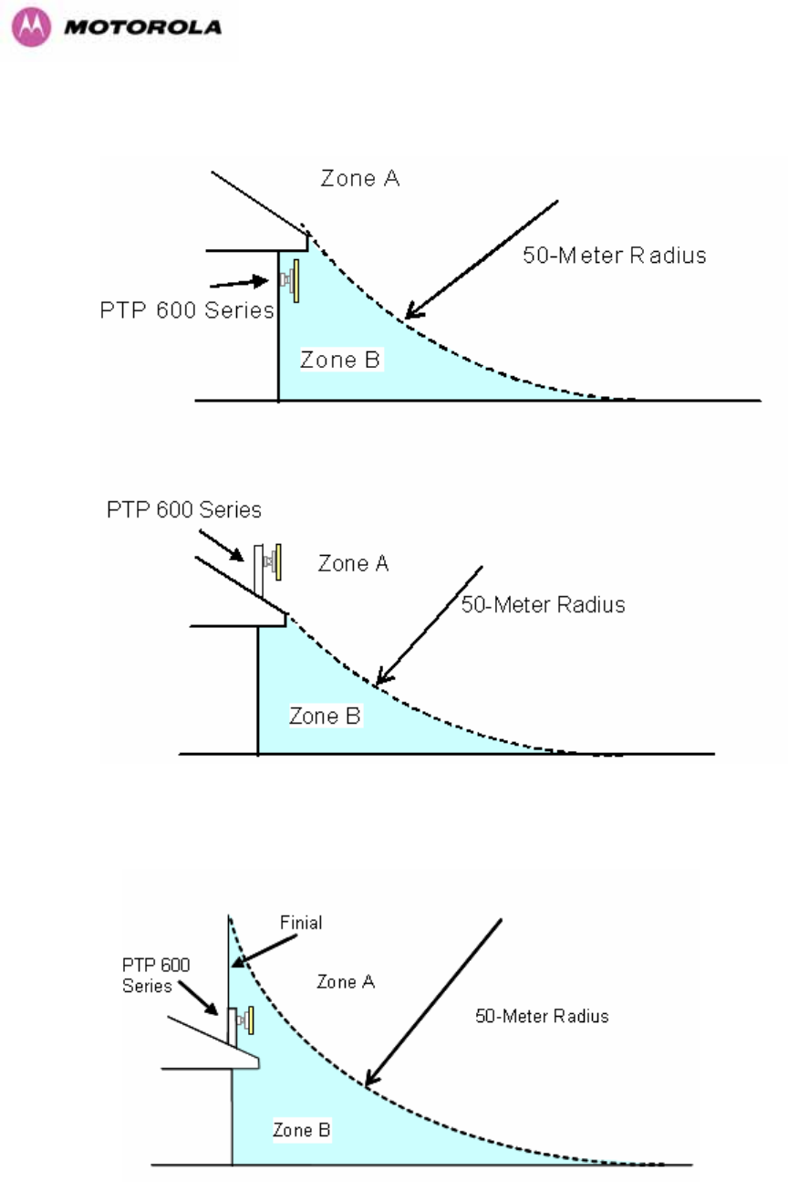
11.1.1 Lightning Protection Zones
The installation of the ODU can be classified into two different lightning protection zones.
Zone A — In this zone a direct lighting strike is possible.
Zone B — In this zone a direct lightning strike is unusual, but the un-attenuated
electromagnetic field is still present.
The zones are determined using the ‘rolling sphere method’, an imaginary sphere, typically 50
meter in radius is rolled over the structure. All structure points that contact the sphere, (Zone
A) indicate the zone where a direct strike is possible. Similarly points that do not contact the
sphere indicate a zone (zone B) where a direct strike is less likely.

178
The following diagrams (Figure 107 & Figure 108) show this zoning pictorially:
Equipment mounted in Zone A should be capable of carrying the full lightning current.
Mounting of the ODU in Zone A is not recommended. Mounting in Zone A should only be
carried out observing the rules governing installations in Zone A26 Failure to do so may put
structures, equipment and life at risk.
Equipment mounted in Zone B should be grounded using grounding wire of at least 10 AWG.
This grounding wire should be connected to a grounding rod or the building grounding system
before entry in to building.
The 600 Series bridge ODU grounding point can be found on the bottom of the unit. The 600
Series Bridge is supplied with an appropriate grounding lug for attachment to the ODU.
11.2 Detailed Installation
The recommended components for an installation protected for nearby strikes are:
• Grounding Kits — Andrew Type 223158-2 (http://www.andrew.com UT)
• Screened CAT 5e Cable also known as Shielded CAT 5e or CAT 5e STP (Shielded
Twisted Pair)
• NB: Only use Outdoor rated, gel filled CAT5e if it contains a shield.
• Surge Arrestor: Transtector Type ALPU-ORT - 4 per link (www.transtector.com)
• Grounding Stake
• RJ45 screened connectors
• 8 AWG Grounding Cable – Minimum size, preferably 6 or 4
NOTE: There may be a local regulatory requirement to cross bond the CAT 5e cable at
regular intervals to the mast. This may be as frequent as every 10 meters (33 feet)
26 Local regulations may also require the fitting of the 8 AWG ground wire referred below.
179
Figure 107 - ODU mounted in Zones A & B
Figure 108 - Showing how the use of a Finial enables the ODU to be mounted inside Zone B
180
Zone A Zone B
Earth ODU Mandatory Mandatory
Screen Cable Mandatory Mandatory
Surge Arrestor Unit at ODU – ALPU-
ORT Mandatory Mandatory
Earth Cable at Building Entry Mandatory Mandatory
Surge Arrestor Unit at Building Entry
– ALPU-ORT Mandatory Mandatory
Table 22 - Protection Requirements
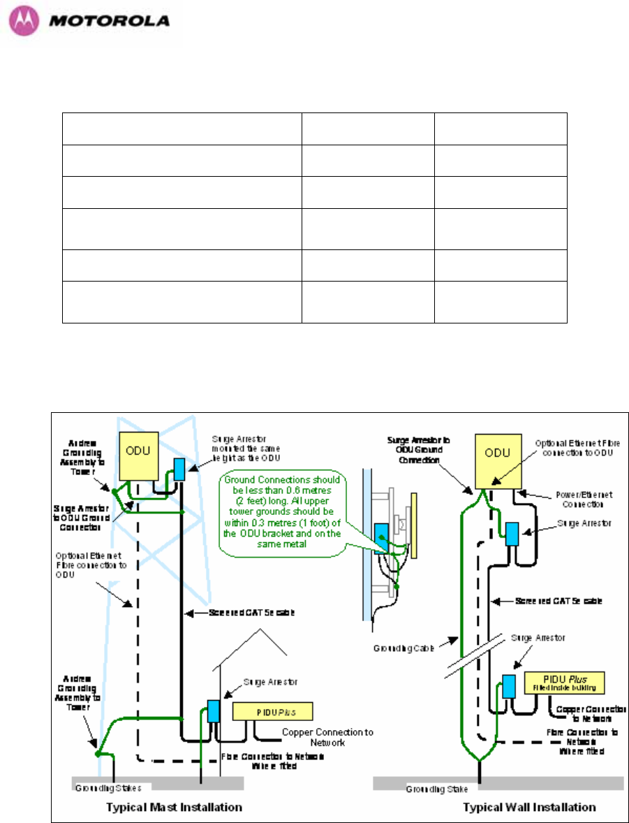
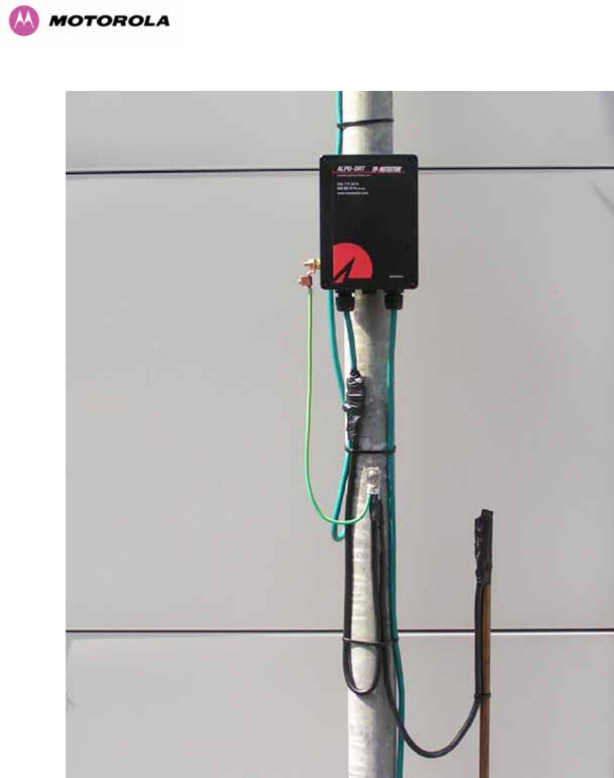
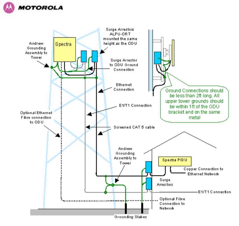
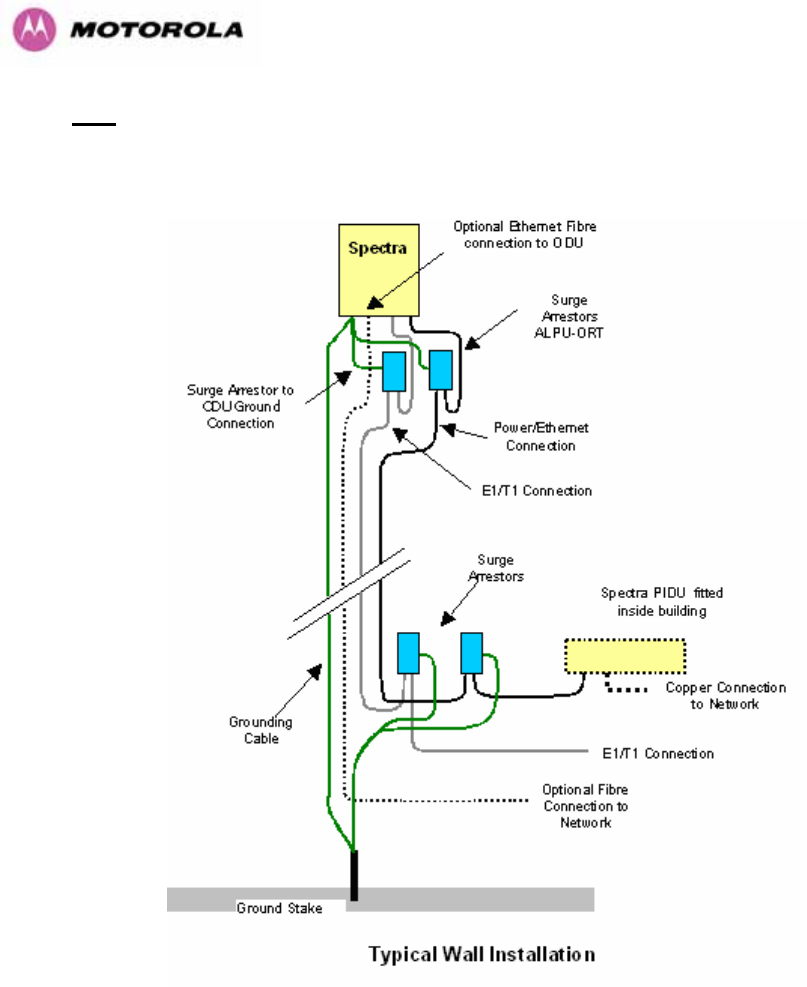
Figure 109 - Diagrammatically showing typical wall and mast installations
182
Figure 111 - Lower Grounding Configuration
An Andrew Grounding Kit and Surge Arrestor Unit must be located at the ODU and reliably
grounded as shown in Figure 95. There may also be a regulatory requirement to crossbond
the screened CAT-5 at regular intervals up the mast. Refer to local regulatory requirements
for further details.

183
A second Surge Arrestor Unit should be mounted at the building entry point and must be
grounded.
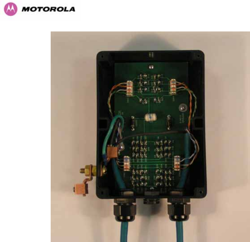
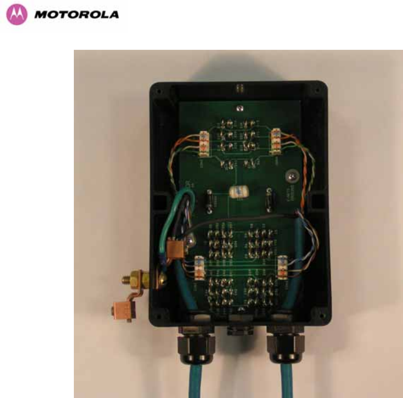
The termination of the CAT-5 Cable into the Surge Arrestor Unit is illustrated in Table, Table
24 and Figure 112. The screen from the cable must be terminated into the ground terminal
within the unit to ensure the continuity of the screen. Earth Sleeving should be used to cover
the shield ground connection to prevent internal shorting within the unit.
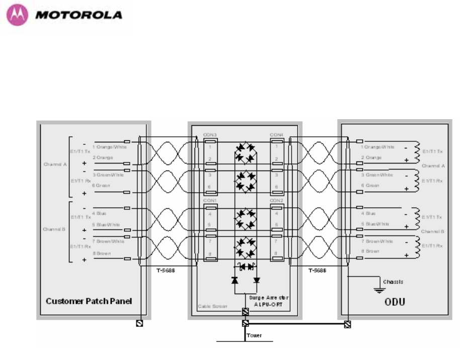
Terminal Identification Conductor RJ45 Pin
CON3 Pin 1 Orange/White 1
CON3 Pin 2 Orange 2
CON3 Pin 3 Green/White 3
CON3 Pin 6 Green 6
CON1 Pin 4 Blue 4
CON1 Pin 5 Blue/White 5
CON1 Pin 7 Brown/White 7
CON1 Pin 8 Brown 8
Table 23 - Surge Arrestor ALPU-ORT Cable 1 Termination
Terminal Identification Conductor RJ45 Pin
CON4 Pin 1 Orange/White 1
CON4 Pin 2 Orange 2
CON4 Pin 3 Green/White 3
CON4 Pin 6 Green 6
CON2 Pin 4 Blue 4
CON2 Pin 5 Blue/White 5
CON2 Pin 7 Brown/White 7
CON2 Pin 8 Brown 8
Table 24 - Surge Arrestor ALPU-ORT Cable 2 Termination
184
Figure 112 - Surge Arrestor ALPU-ORT Connection Illustration
Note: Cable screens have been sleeved.
185
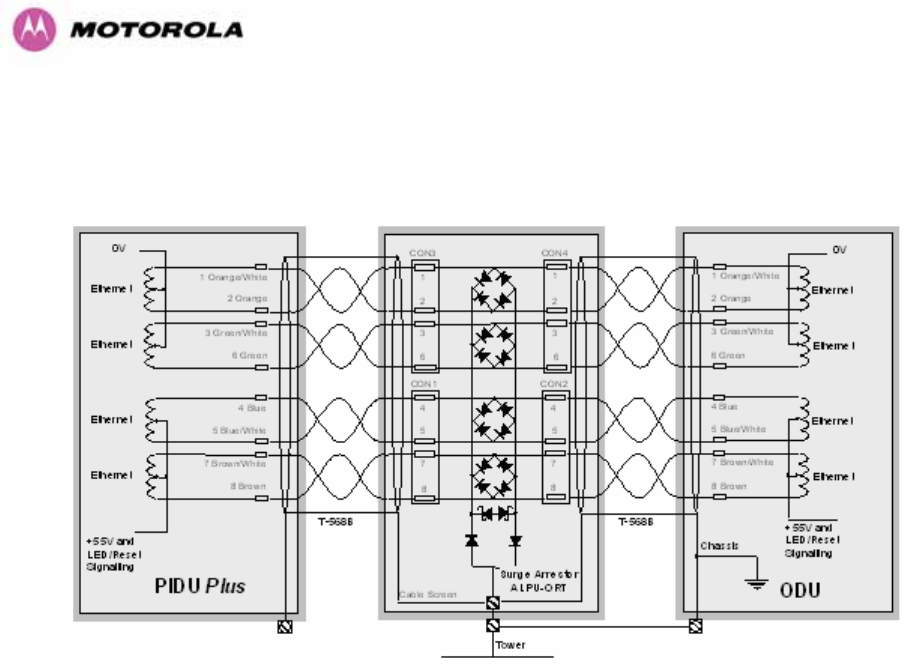
11.3 Testing Your Installation
If you have followed the above instructions you will have wired your system to the following
diagram:
Figure 113 - Simplified Circuit Diagram (Only One Transtector Shown For Clarity)
11.3.1 Pre-Power Testing
Before plugging in the RJ45 to the PIDU check the impedances at the RJ45 as described in
10.1.3.
11.3.2 Post-Power Testing
The Correct Operation is as follows
1. Connect the RJ45 to the PIDU and apply power to the PIDU, the power LED should
illuminate continuously.
2. 45 seconds after powering, the Ethernet LED should be observed starting with 10 slow
flashes.
3. If there is a network connection the Ethernet LED will then show Ethernet activity.
The Ethernet LED does not flash 10 times
Failure of the Ethernet LED to illuminate can be due to wiring to pins 4&5 and 7&8 being
incorrect, for example if the wiring to pins 4 and 7 are crossed.

186
The Ethernet LED flashes ten times but irregularly
Irregularly flashing, seen as a short gap followed by a long gap, indicates that the ODU has
booted in recovery mode. This may be due to either the installation wiring or a corrupted main
code image in the ODU.
The Ethernet LED flashes ten times but does not show Ethernet activity
Failure of the Ethernet LED to show Ethernet activity can be due to wiring to pins 1&2 and
3&6 being incorrect, for example if the wiring to pins 1 and 3 are crossed.
The Ethernet connection to the network is only 10/100 BaseT, when 1000 BaseT was
expected
It is likely there is a fault with the wiring to pins 4&5 and 7&8.

187
12 Wind Loading
12.1 General
Antennas and electronic equipment mounted on towers or pole mounted on buildings will
subject the mounting structure to lateral forces when there is appreciable wind. Antennas are
normally specified by the amount of force (in pounds) for specific wind strengths.
The magnitude of the force depends on both the wind strength and size of the antenna.
12.2 Calculation of Lateral Force
The 600 Series bridge with or without the integral antenna is essentially a flat structure and so
the magnitude of the lateral force can be estimated from:
Force (in pounds) = 0.0042 . A . v2
Where A is the surface area in square feet and v is the wind speed in miles per hour.
The lateral force produced by a single 600 Series bridge (integrated or connectorized model)
at different wind speeds is shown in Table 25 and Table 26.
Lateral Force (Pound) at wind speed (mph)
Largest Surface
Area (sq ft)
80 100 120 140 150
PTP 600 Series
Bridge - Integrated 1.36 37 57 82 112 129
PTP 600 Series
Bridge -
Connectorized
1.00 27 42 60 82 95
Table 25 - Lateral Force – Imperial

188
Lateral Force (kg) at wind speed (m/s)
Largest Surface
Area (sq m)
30 40 50 60 70
PTP 600 Series
Bridge - Integrated 0.130 12 22 34 49 66
PTP 600 Series
Bridge -
Connectorized
0.093 9 16 24 35 48
Table 26 - Lateral Force – Metric
Note: When the connectorized version of 600 Series bridge is used with external antennas,
the figures from the antenna manufacturer for lateral force should be included to calculate to
total loading on the mounting structure.
12.3 Capabilities of the PTP 600 Series Bridges
The structure and mounting brackets of the PTP Series systems are capable of withstanding
wind speeds up to 151mph (242 kph). The installer should ensure that the structure to which
the 600 Series Bridge is fixed to is also capable of withstanding the prevalent wind speeds
and loads.
12.4 Wind Speed Statistics
Installers are recommended to contact the national meteorological office for the country
concerned to identify the likely wind speeds prevalent at the proposed location. This will
enable the installer to estimate the total wind loading on the support structures.
Examples of the sort of statistics that are available are:
USA - Reported Fastest Single Wind Velocities for Selected U.S. Cities
(Source: National Weather Service)
City, State Wind Velocity
(mph)
Bismarck, North Dakota 72
Buffalo, New York 91

189
Chicago, Illinois 87
Hatteras, North Carolina 110
Miami, Florida 132
New York, New York 99
Pensacola, Florida 114
UK Meteorological Office, www.meto.gov.uk
Peak wind speed contour maps can be found as Fig 3a/3b at:
http://www.meto.gov.uk/education/historic/1987.html
190
13 PTP 600 Series Bridge – Connectorized Model
13.1 Scope
This section details the changes and additional features relevant to the connectorized version
of the PTP 600 Series systems, OS 58C.
13.2 Product Description
13.2.1 Hardware
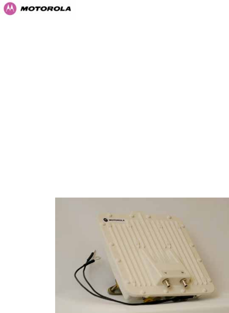
The Connectorized PTP 600 Series Bridge is a variant designed to provide the system
integrator and installer with the ability to provide extra capability to cope with very difficult
radio links compared to the PTP 600 Series Integrated model. The variant allows the use of a
variety of externally mounted antennas, either Flat Plate or Dish, which have higher gains
than provided by the integrated antenna that is normally used.
Figure 114 – Connectorized 600 Series Bridge Outdoor Unit

191
13.2.2 Antenna Choices – 5.8 GHz
The integrated antenna has a gain of 23 dBi.
In non-FCC regions antenna choice is not restricted but any region specific EIRP limit should
be obeyed, see Table 6 in Section 5.2 “Region Codes”
In FCC regions external antennas from the list in Section 13.7 “Antennas for USA / Canada –
5.8 GHz” can be used with the Connectorized version of the 600 Series Bridge. These are
approved by the FCC for use with the product and are basically constrained by the following
limits:
• Single Polarization Flat Plate Antennas – up to 28dBi per antenna.
• Single/Dual Polarization Parabolic Dish Antennas – up to 37.7dBi per polarization or
antenna.
In FCC regions when using external antennas – cable loss between the connectorized
version of the 600 Series Bridge and the antenna ports must not be less than 1.2dB
13.2.3 Antenna Choices – 5.4 GHz
The integrated antenna has a gain of 23 dBi.
In FCC regions external antennas from the list in Section 13.8 “Antennas for USA / Canada –
5.4GHz” can be used with the Connectorized version of the 600 Series Bridge. These are
approved by the FCC for use with the product and are basically constrained by the following
limits:
• Single/Dual Polarization Parabolic Dish Antennas – up to 34.6dBi per polarization or
antenna.
In FCC regions when using external antennas – cable loss between the connectorized
version of the 600 Series Bridge and the antenna ports must not be less than 1.2dB
192
13.3 Software/Features
The variant operates in the same way as the basic 600 Series bridge and is released initially
with the feature set of the Connectorized 600 Series bridge. The areas where the
functionality is modified are:
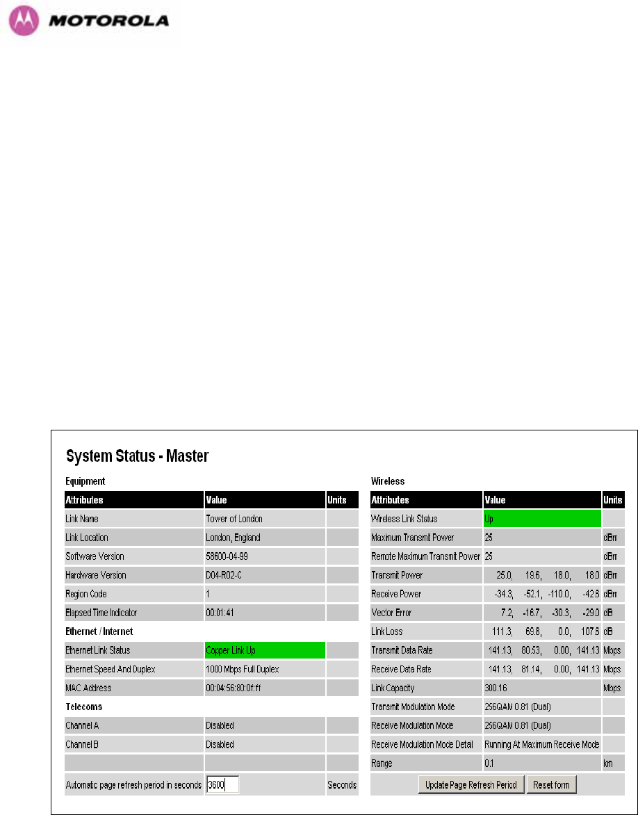
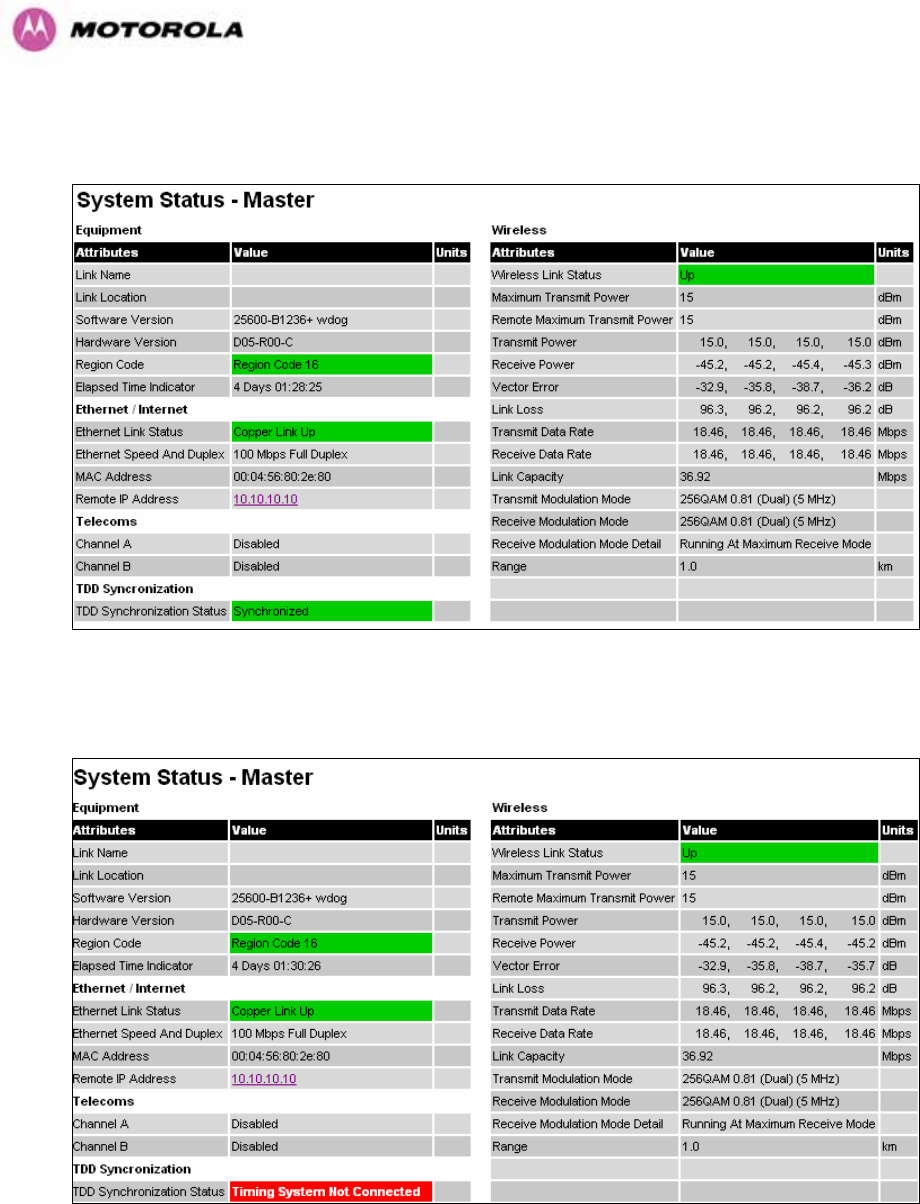
13.3.1 Status Page
The link loss calculation presented on the Status Page of the management interface has to be
modified to allow for the increased antenna gains at each end of the link. The manufacturing
process of the Connectorized 600 Series Bridge configures the standard hardware of the unit
for use with external antennas. The installer is prompted, as part of the installation process, to
enter the gain of the external antenna(s) and cable losses at each end of the link.
Peer-to-peer messaging is used to pass the effective antenna gain to each end of the link so
that the link loss calculations can be correctly computed.
Figure 115 - Connectorized 600 Series bridge Status Page
194
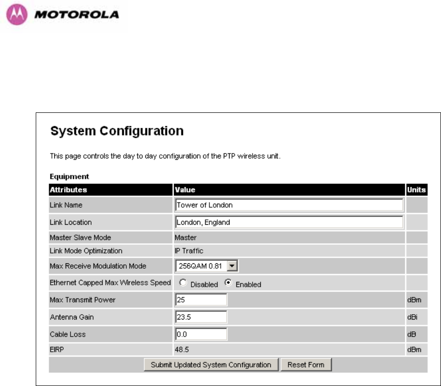
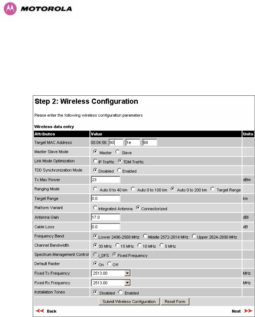
13.3.3 Installation Pages
The installer is prompted to enter the Antenna Gain and Cable Loss (Connectorized PTP 600
Series Bridge to antenna) at each end of the link. The Installation Page(s) is shown as Figure
117 to Figure 119.
Figure 117 - Connectorized PTP 600 Series Bridge ‘Installation Wizard’ Page
Antenna Gain: Gain of the antenna you are connecting to the unit, see Table 28.
Cable Loss: Loss in the cable between the ODU and the antenna. Note: In the event that
there is a significant difference in length of the antenna cables for the two antenna ports, then
the average value should be entered.
195
Spectrum Management Control: Is used to configure the 600 Series Bridge Spectrum
Management features, see Section 8.3.7 for more details. iDFS is the abbreviation for
intelligent Dynamic Frequency Selection, which continually monitors the 5.8 GHz spectrum
looking for the channel with the lowest level of on channel and co-channel interference. Fixed
frequency mode allows the installer to fix the Transmit and receive frequencies on the units.
The frequencies may be configured symmetrically or asymmetrically.
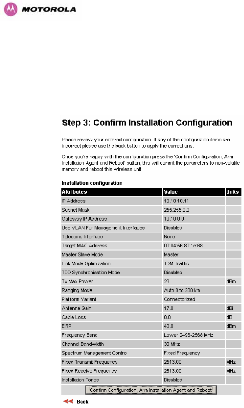
Figure 118 - Connectorized 600 Series bridge ‘Confirm Installation’ Page
196
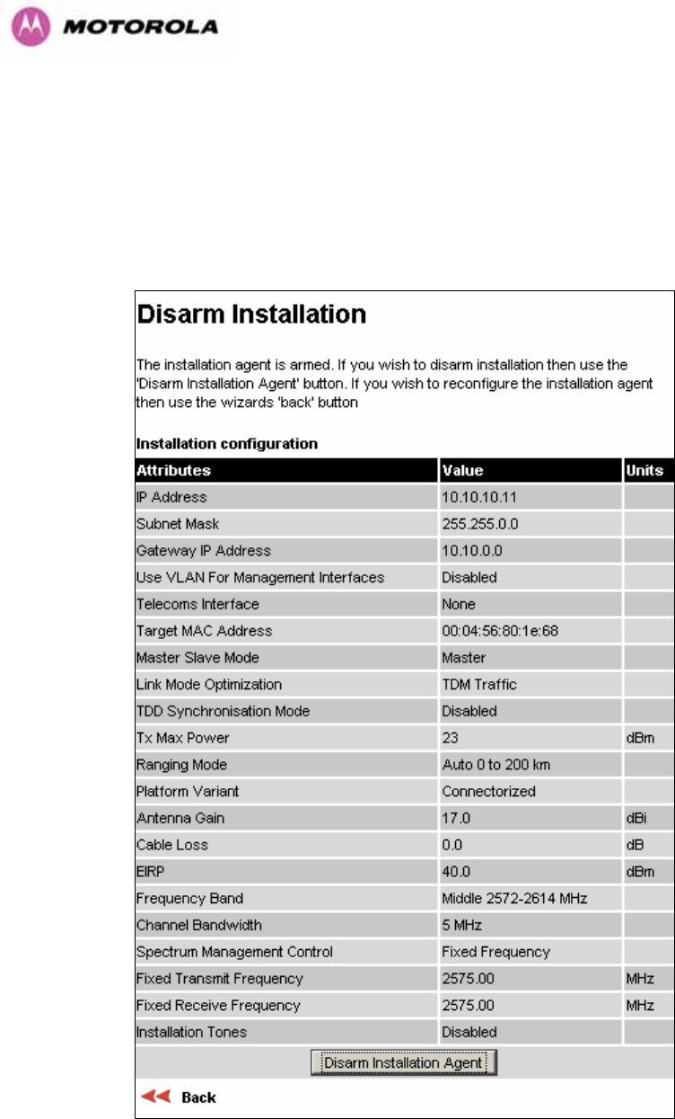
EIRP The Confirm Installation Page displays the EIRP (Effective Isotropic Radiated Power),
which describes the strength of the radio signal leaving the wireless unit. This allows the
operator to verify that their link configuration (Max Transmit Power, Antenna Gain and Cable
Loss) do not cause the link to exceed any applicable regulatory limit.
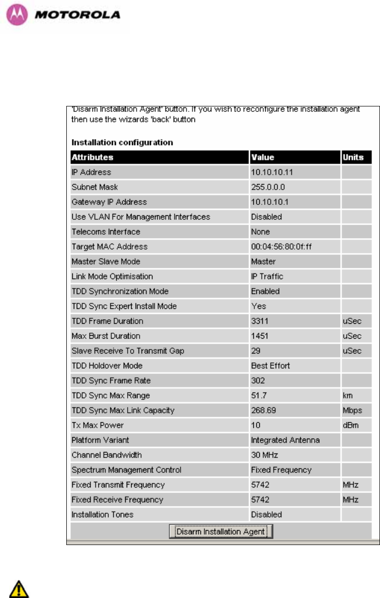
Figure 119 - Connectorized 600 Series bridge ‘Disarm Installation’ Page

197
13.4 Deployment Considerations
The majority of radio links can be successfully deployed with the 600 Series bridge. It should
only be necessary to use external antennas where the Link Budget Calculator indicates
marginal performance for a specific link – for example when the link is heavily obscured by
dense woodland on an NLOS link or extremely long LOS links (>80km or > 50 miles) over
water.
The external antennas can be either dual-polarization (as the integrated antenna) or two
single polarized antennas can be used in a spatially diverse configuration. It is expected that
the dual-polarization antennas would normally be used to simplify the installation process;
spatially diverse antennas may provide additional fade margin on very long LOS links where
there is evidence of correlation of the fading characteristics on Vertical and Horizontal
polarizations.
Dual polarization antennas (with a gain greater than the integrated antenna) are currently only
available in parabolic dish form.
13.5 Link Budget
An estimate of the link budget for a specific application can be obtained by using the Motorola
Systems link estimation tools. For more information see the Motorola web site.
13.6 Regulatory Issues
In countries where FCC regulations are not relevant, installations should conform to any
applicable local regulations for the Equivalent Isotropic Radiated Power (EIRP).
Ensuring compliance becomes more complex when the connectorized unit is used with
external antennas which may be locally sourced. With higher gain external antennas fitted,
the Maximum Transmit power may need to be reduced for operation in specific countries.
See Table 6 in Section 5.2 for any EIRP restrictions that may apply in your region.
13.6.1 Antenna Choice (FCC Regions Only)
The antennas which can be deployed with the Connectorized 600 Series Bridge are shown in
Table 28.

198
13.6.2 Cable Losses (FCC Regions Only)
The FCC approval for the product is based on tests with a cable loss between the units of
approximately 1.2dB at 5.8GHz. The use of lower cable losses would result in the installation
being outside the FCC rules.
As an indication, 1.2dB of cable loss corresponds to the following cable lengths excluding
connector losses (source: Times Microwave).
Length for 1.2dB Cable Loss at 5.8GHz
Cable (ft) (m)
LMR100 1.9 0.6
LMR200 4.6 1.4
LMR300 7.25 2.2
LMR400 11.1 3.4
LMR600 16.5 5.0
Table 27 - Cable Losses per Length
13.7 Antennas for USA / Canada – 5.8 GHz
Manufacturer Antenna Type Gain
(dBi) Flat
Plate Paraboli
c Dish
Andrew Andrew 1-foot Flat Panel, FPA5250D12-N
(23.6dBi) 23.6 Y
Andrew Andrew 2-foot Flat Panel, FPA5250D24-N
(28dBi) 28 Y
Gabriel Gabriel 1-foot Flat Panel, DFPD1-52 (23.5dBi) 23.5 Y
Gabriel Gabriel 2-foot Flat Panel, DFPD2-52 (28dBi) 28 Y
MTI MTI 17 inch Diamond Flat Panel, MT-485009
(23dBi) 23 Y
MTI MTI 15 inch Dual-Pol Flat Panel,
MT-485025/NVH (23dBi) 23 Y
MTI MTI 2 ft Directional Flat Panel, MT-20004
(28dBi) 28 Y
MTI MTI 2 ft Flat Panel, MT-486001 (28dBi) 28 Y
RFS RFS 1-foot Flat Panel, MA0528-23AN (23dBi) 23 Y
RFS RFS 2-foot Flat Panel, MA0528-28AN (28dBi) 28 Y
Telectronics Teletronics 2-foot Flat Plate Antenna,
ANT-P5828 (28dBi) 28 Y
Andrew Andrew 2-foot Parabolic, P2F-52 (29.4dBi) 29.4 Y
Andrew Andrew 2-foot Dual-Pol Parabolic, PX2F-52
(29.4dBi) 29.4 Y

199
Manufacturer Antenna Type Gain
(dBi) Flat
Plate Paraboli
c Dish
Andrew Andrew 3-foot Parabolic, P3F-52 (33.4dBi) 33.4 Y
Andrew Andrew 3-foot Dual-Pol Parabolic, PX3F-52
(33.4dBi) 33.4 Y
Andrew Andrew 4-foot Parabolic, P4F-52 (34.9dBi) 34.9 Y
Andrew Andrew 4-foot Dual-Pol Parabolic, PX4F-52
(34.9dBi) 34.9 Y
Andrew Andrew 6-foot Parabolic, P6F-52 (37.6dBi) 37.6 Y
Andrew Andrew 6-foot Dual-Pol Parabolic, PX6F-52
(37.6dBi) 37.6 Y
Gabriel Gabriel 2-foot High Performance QuickFire
Parabolic, HQF2-52-N 28.2 Y
Gabriel Gabriel 4-foot High Performance QuickFire
Parabolic, HQF4-52-N 34.4 Y
Gabriel Gabriel 6-foot High Performance QuickFire
Parabolic, HQF6-52-N 37.4 Y
Gabriel Gabriel 2-foot High Performance Dual QuickFire
Parabolic, HQFD2-52-N 28.1 Y
Gabriel Gabriel 4-foot High Performance Dual QuickFire
Parabolic, HQFD4-52-N 34.3 Y
Gabriel Gabriel 6-foot High Performance Dual QuickFire
Parabolic, HQFD6-52-N 37.3 Y
Gabriel Gabriel 2-foot Standard QuickFire Parabolic,
QF2-52-N 28.5 Y
Gabriel Gabriel 2-foot Standard QuickFire Parabolic,
QF2-52-N-RK 28.5 Y
Gabriel Gabriel 2.5-foot Standard QuickFire Parabolic,
QF2.5-52-N 31.2 Y
Gabriel Gabriel 4-foot Standard QuickFire Parabolic,
QF4-52-N 34.8 Y
Gabriel Gabriel 4-foot Standard QuickFire Parabolic,
QF4-52-N-RK 34.8 Y
Gabriel Gabriel 6-foot Standard QuickFire Parabolic,
QF6-52-N 37.7 Y
Gabriel Gabriel 2-foot Standard Dual QuickFire
Parabolic, QFD2-52-N 28.4 Y
Gabriel Gabriel 2.5-foot Standard Dual QuickFire
Parabolic, QFD2.5-52-N 31.1 Y
Gabriel Gabriel 2-foot Standard Dual QuickFire
Parabolic, QFD2-52-N-RK 28.4 Y
Gabriel Gabriel 4-foot Standard Dual QuickFire
Parabolic, QFD4-52-N 34.7 Y
Gabriel Gabriel 4-foot Standard Dual QuickFire
Parabolic, QFD4-52-N-RK 34.7 Y
Gabriel Gabriel 6-foot Standard Dual QuickFire
Parabolic, QFD6-52-N 37.7 Y
RadioWaves Radio Waves 2-foot Dual-Pol Parabolic, SPD2-
5.2 (28.1dBi) 28.1 Y

200
Manufacturer Antenna Type Gain
(dBi) Flat
Plate Paraboli
c Dish
RadioWaves Radio Waves 2-foot Parabolic, SP2-5.2 (29.0dBi) 29 Y
RadioWaves Radio Waves 3-foot Dual-Pol Parabolic, SPD3-
5.2 (31.1dBi) 31.1 Y
RadioWaves Radio Waves 3-foot Parabolic, SP3-5.2 (31.4dBi) 31.4 Y
RadioWaves Radio Waves 4-foot Dual-Pol Parabolic, SPD4-
5.2 (34.4dBi) 34.4 Y
RadioWaves Radio Waves 4-foot Parabolic, SP4-5.2 (34.8dBi) 34.8 Y
RadioWaves Radio Waves 6-foot Dual-Pol Parabolic, SPD6-
5.2 (37.5dBi) 37.5 Y
RadioWaves Radio Waves 6-foot Parabolic, SP6-5.2 (37.7dBi) 37.7 Y
RadioWaves Radio Waves 2-foot Parabolic, SP2-2/5 (28.3dBi) 28.3 Y
RadioWaves Radio Waves 3-foot Parabolic, SP3-2/5 (31.4dBi) 31.4 Y
RadioWaves Radio Waves 4-foot Parabolic, SP4-2/5 (34.6dBi) 34.6 Y
RadioWaves Radio Waves 6-foot Parabolic, SP6-2/5 (37.7dBi) 37.7 Y
RFS RFS 2-foot Parabolic, SPF2-52AN or SPFX2-
52AN (27.9dBi) 27.9 Y
RFS RFS 3-foot Parabolic, SPF3-52AN or SPFX3-
52AN(31.4dBi) 31.4 Y
RFS RFS 4-foot Parabolic, SPF4-52AN or SPFX4-
52AN(33.9dBi) 33.9 Y
RFS RFS 6-foot Parabolic, SPF6-52AN or SPFX6-
52AN (37.4dBi) 37.4 Y
RFS RFS 2-foot HP Parabolic, SDF2-52AN or
SDFX2-52AN (31.4dBi) 31.4 Y
RFS RFS 4-foot HP Parabolic, SDF4-52AN or
SDFX4-52AN (33.9dBi) 33.9 Y
RFS RFS 6-foot HP Parabolic, SDF6-52AN or
SDFX6-52AN (37.4dBi) 37.4 Y
StellaDoradus StellaDoradus 45 inch Parabolic Antenna,
58PSD113 33.8 Y
Table 28 - Allowed Antennas for Deployment in USA/Canada – 5.8 GHz

201
13.8 Antennas for USA - 5.4 GHz
Manufacturer Antenna Type Gain
(dBi) Parabolic
Dish
Andrew Andrew 2-foot Parabolic, P2F-52 (29.4dBi) 29.4 Y
Andrew Andrew 2-foot Dual-Pol Parabolic, PX2F-52 (29.4dBi) 29.4 Y
Andrew Andrew 3-foot Parabolic, P3F-52 (33.4dBi) 33.4 Y
Andrew Andrew 3-foot Dual-Pol Parabolic, PX3F-52 (33.4dBi) 33.4 Y
Andrew Andrew 4-foot Parabolic, P4F-52 (34.9dBi) 34.9 Y
Andrew Andrew 4-foot Dual-Pol Parabolic, PX4F-52 (34.9dBi) 34.9 Y
Gabriel Gabriel 2-foot High Performance QuickFire Parabolic,
HQF2-52-N 28.2 Y
Gabriel Gabriel 4-foot High Performance QuickFire Parabolic,
HQF4-52-N 34.4 Y
Gabriel Gabriel 2-foot High Performance Dual QuickFire
Parabolic, HQFD2-52-N 28.1 Y
Gabriel Gabriel 4-foot High Performance Dual QuickFire
Parabolic, HQFD4-52-N 34.3 Y
Gabriel Gabriel 2-foot Standard QuickFire Parabolic,
QF2-52-N 28.5 Y
Gabriel Gabriel 2-foot Standard QuickFire Parabolic,
QF2-52-N-RK 28.5 Y
Gabriel Gabriel 2.5-foot Standard QuickFire Parabolic, QF2.5-
52-N 31.2 Y
Gabriel Gabriel 4-foot Standard QuickFire Parabolic,
QF4-52-N 34.8 Y
Gabriel Gabriel 4-foot Standard QuickFire Parabolic,
QF4-52-N-RK 34.8 Y
Gabriel Gabriel 2-foot Standard Dual QuickFire Parabolic, QFD2-
52-N 28.4 Y
Gabriel Gabriel 2.5-foot Standard Dual QuickFire Parabolic,
QFD2.5-52-N 31.1 Y
Gabriel Gabriel 2-foot Standard Dual QuickFire Parabolic, QFD2-
52-N-RK 28.4 Y
Gabriel Gabriel 4-foot Standard Dual QuickFire Parabolic, QFD4-
52-N 34.7 Y
Gabriel Gabriel 4-foot Standard Dual QuickFire Parabolic, QFD4-
52-N-RK 34.7 Y
RadioWaves Radio Waves 2-foot Dual-Pol Parabolic, SPD2-5.2
(28.1dBi) 28.1 Y
RadioWaves Radio Waves 2-foot Parabolic, SP2-5.2 (29.0dBi) 29 Y
RadioWaves Radio Waves 3-foot Dual-Pol Parabolic, SPD3-5.2
(31.1dBi) 31.1 Y
RadioWaves Radio Waves 3-foot Parabolic, SP3-5.2 (31.4dBi) 31.4 Y
RadioWaves Radio Waves 4-foot Dual-Pol Parabolic, SPD4-5.2
(34.4dBi) 34.4 Y
RadioWaves Radio Waves 4-foot Parabolic, SP4-5.2 (34.8dBi) 34.8 Y
RadioWaves Radio Waves 2-foot Parabolic, SP2-2/5 (28.3dBi) 28.3 Y

202
Manufacturer Antenna Type Gain
(dBi) Parabolic
Dish
RadioWaves Radio Waves 3-foot Parabolic, SP3-2/5 (31.4dBi) 31.4 Y
RadioWaves Radio Waves 4-foot Parabolic, SP4-2/5 (34.6dBi) 34.6 Y
RFS RFS 2-foot Parabolic, SPF2-52AN or SPFX2-52AN
(27.9dBi) 27.9 Y
RFS RFS 3-foot Parabolic, SPF3-52AN or SPFX3-
52AN(31.4dBi) 31.4 Y
RFS RFS 4-foot Parabolic, SPF4-52AN or SPFX4-
52AN(33.9dBi) 33.9 Y
RFS RFS 2-foot HP Parabolic, SDF2-52AN or SDFX2-52AN
(31.4dBi) 31.4 Y
RFS RFS 4-foot HP Parabolic, SDF4-52AN or SDFX4-52AN
(33.9dBi) 33.9 Y
Table 29 - Allowed Antennas for Deployment in USA/Canada – 5.4 GHz

203
13.9 Installation
The section covers the generic installation instructions for the Connectorized versions of the
PTP 600 Series point-to-point wireless Ethernet bridges. The actual installation procedure will
depend on antenna choice, cable choice, required antenna separation etc.
13.9.1 Antenna Choice
Table 28 shows a wide variety of antennas that can be used with the Connectorized 600
Series bridge. The main selection criteria will be the required antenna gain. The secondary
criteria should be the ease of mounting and alignment. For example the Radio Waves
Parabolic dishes are supplied with a mount that allows adjustment for alignment independent
of the actual antenna mounting. This type of antenna is much easier to align than those that
have to be rotated around the mounting pole for alignment.
13.9.2 Cables and Connectors
Cables should be selected using the above criteria. However it should be noted that a cable
of a type similar to LMR400 is a lot more difficult to handle and route than a cable of a type
similar to LMR100.
Motorola recommends the use of weatherproof connectors -- preferably, ones that come
supplied with adhesive lined heat shrink sleeve that is fitted over the cable/connector
interface.
The connectors required at the Connectorized 600 Series bridge end of the antenna cables
are N-Type Male.
The connectors required at the antenna end of the antenna cables is dependant on the
antenna type chosen.
13.9.3 Tools
The tools required for mounting a Connectorized 600 Series bridge unit are the same as
those required for an Integrated 600 Series bridge detailed in Section 7.3. The tools required
for mounting the antennas are specific to the antenna chosen. The installer should refer to the
antenna manufacturer’s instructions.

204
13.9.4 Miscellaneous supplies
The following miscellaneous supplies will be required:
• Cable ties, cable cleats – for securing cables
• Self-amalgamating tape – to weatherproof the RF connectors
• PVC tape – for additional protection of the RF connectors and securing cables
13.9.5 Mounting the Connectorized 600 Series Bridge
A Connectorized 600 Series bridge is shipped with the same bracket as supplied with an
Integrated unit. Details on the use of this bracket can be found in Section 3.3.7. The 600
Series Bridge should be mounted in a position that gives it maximum protection from the
elements, but still allows easy access for making off the various connections and applying the
recommended weatherproofing.
When using dual polar antennas the Connectorized 600 Series bridge should be mounted in
such a position as to minimize the cable length, keeping losses to a minimum (taking into
account the minimum cable lengths required by the FCC regulations, see Section 13.7).
When using separate antennas the Connectorized 600 Series Bridge should be mounted in
such a position as to minimize both cable runs between the unit and the antennas. It is not
necessary to mount the Connectorized 600 Series Bridge at the mid point between the
antennas.
13.9.6 Mounting the antennas
The Antennas should be mounted according to the manufacturer’s instructions. Actual
antenna position will depend on the available mounting positions and link requirements. It
may be necessary to mount the antennas 20m apart or at a certain distance from the ground
to get the desired results.

205
13.9.7 Alignment Process
When aligning antennas deployed with a Connectorized 600 Series bridge unit it may not be
possible to hear the alignment tone emanating from the unit. In this case it may be necessary
for a second installer to assist in the operation. Alternatively, it may be possible to extend the
tube on the supplied stethoscope to give a longer reach.
Tip: Fine antenna alignment can sometimes be achieved by tightening and loosening the
bolts on either side of the antenna mounting bracket, rather than trying to turn the whole
bracket on the mounting pole.
13.9.8 Aligning Dual Polar Antennas
The process for aligning a dual polar antenna is the same as aligning an Integrated unit with
an integrated antenna. This procedure is detailed in Section 7.7.11.
13.9.9 Aligning Separate Antennas
When using separate antennas to achieve spatial diversity, one should be mounted with
Horizontal polarization and the other with Vertical polarization.
The following steps should be followed:
Step 1: Mount the Antennas
Step 2: Mount the connectorized version of the PTP 600 Series Bridge unit
Step 3: Route and make off the ends of the Antenna cables
Step 4: Connect the antenna cables at the antennas
Step 5: Connect one of the antenna cables at the Connectorized version of the 600
Series bridge unit.
Step 6: Connect the Connectorized 600 Series Bridge ODU to PIDU Plus cable and
configure the unit as described in Section 7.7.
Step 7: Align the connected antenna using the tones as described in Section 7.7.11.
Step 8: Connect the other antenna to the Connectorized 600 Series bridge.
Step 9: Disconnect the cable to the already aligned antenna.
Step 10: Align the second antenna using the tones as described in Section 7.7.11.
Step 11: Re-connect the second antenna to the Connectorized 600 Series bridge (Note:
you will notice the tone pitch increase as you re-connect the second antenna due
to the additional received signal).
Step 12: Use the relevant status web pages to check that you are getting the results you
expect from your link planning.
Step 13: Complete the installation as detailed below.
206
13.9.10 Completing the Installation
The installation should be completed by checking all mounting nuts bolts and screws,
securing all cables and weatherproofing the installation.
Warning: Finally tightening the antenna mountings may cause the antenna alignment to be
altered, due to distortion in the mounting bracket caused by action of tightening. It is
recommended that the installation tone be left turned on (armed) during this process so that
any movement can be noticed and counteracted by tightening the other side of the bracket.
13.9.11 Antenna Cable Fixing
Cables should be secured in place using cable ties, cleats or PVC tape. Care should be
taken to ensure that no undue strain is placed on the connectors on both the Connectorized
600 Series bridge and the Antennas and also to ensure that the cables do not flap in the
wind. Flapping cables are prone to damage and induce unwanted vibrations in the mast to
which the units are attached.
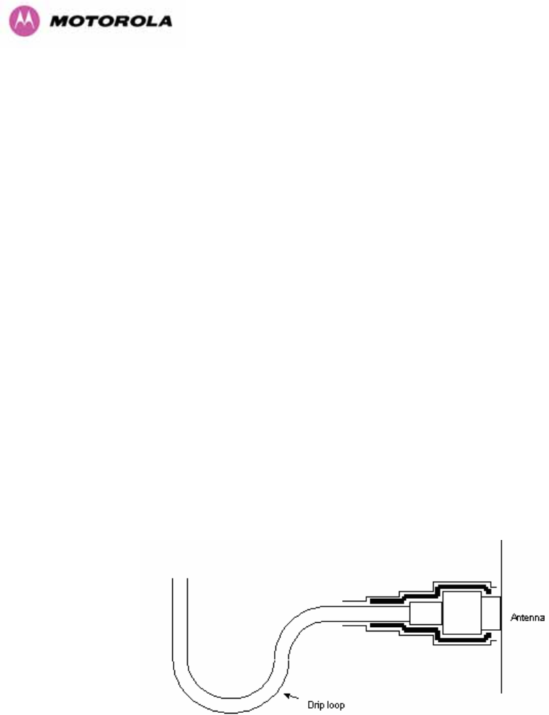
13.9.12 Antenna Connection Weatherproofing
Where a cable connects to an antenna or unit from above, a drip loop should be left to ensure
that water is not constantly channeled towards the connector.
Figure 120 - Forming a Drip Loop
207
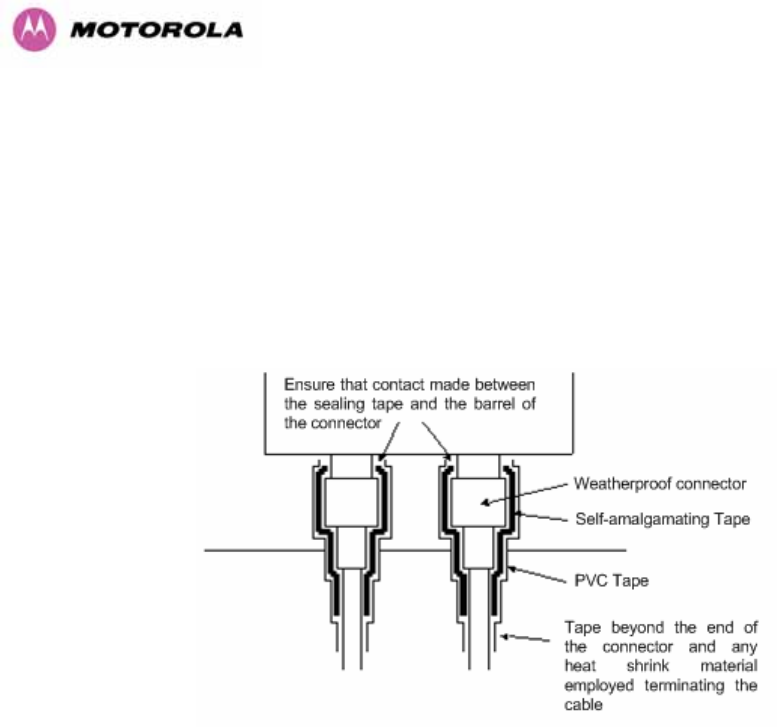
All joints should be weatherproofed using self-amalgamating tape. It is recommended that a
layer of PVC tape be placed over the self-amalgamating tape to protect the joint while the
self-amalgamating tape cures and gives additional protection. Figure 121 shows this
diagrammatically for the 600 Series bridge end of the antenna cables. If the antenna
manufacturer has not supplied guidance on this matter, the same technique should be
employed at the antenna end of the cable.
Figure 121 - Weatherproofing the Antenna Connections
208
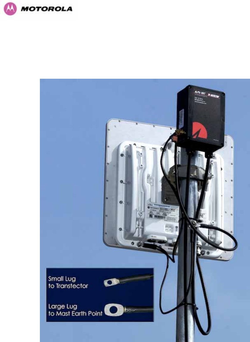
13.10 Additional Lightning Protection
The following guidelines should be applied in addition to those described in Section 11
”Lightning Protection”.
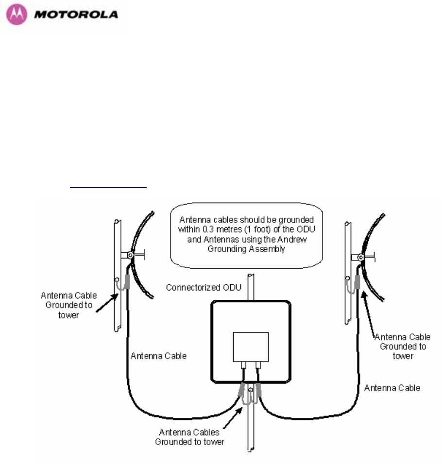
13.10.1 ODU Mounted Outdoors
Where the ODU is mounted outdoors and is mounted some distance from the antenna, it is
advisable to add additional grounding by utilizing Andrew Assemblies (such as Andrew Type
223158 www.andrew.com) as shown in Figure 122.
Figure 122- Additional Grounding When Using Connectorized Units
209
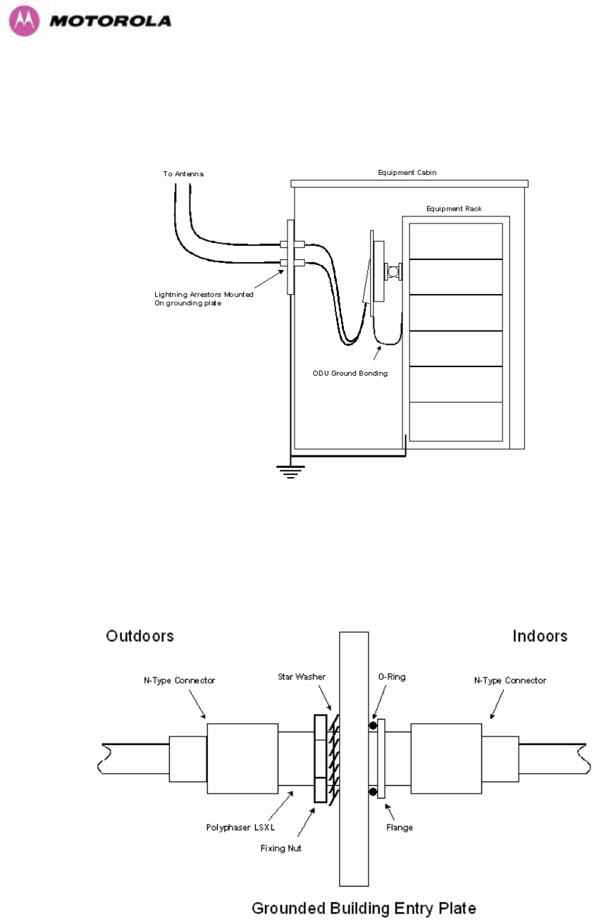
13.10.2 ODU Mounted Indoors
Where the ODU is mounted indoors, lightning arrestors should be deployed where the
antenna cables enter the building as shown in Figure 123.
Figure 123 - Lightning Arrestor Mounting
The lighting arrestors should be ground bonded to the building ground at the point of entry.
Motorola recommends Polyphaser LSXL-ME or LSXL lighting arrestors. These should be
assembled as show in Figure 124.
Figure 124 - Polyphaser Assembly

210
14 TDD Synchronization Configuration and Installation Guide
14.1 Introduction
This Section gives instructions for installing and configuring the TDD (Time Division Duplex)
Synchronization feature for Motorola PTP600 Series bridges. This has many advantages such as:
• Minimising interference between multiple links on a single mast.
• Improving frequency re-use
• Reducing spatial / angular separation between PTP links when installed on the same
mast
• Improving Link Budgets (when using higher Tx power)
This section includes also:
• Wiring Diagrams
• Step-by-Step configuration using web interface.
• Illustrations showing the placement of the GPS box and the recommended components
for installation

211
14.2 TDD Synchronization Installation and Wiring Guidelines
As mentioned in Section 5.8.4, enabling the TDD Synchronization27 feature is a two-stage
process:
1. Install GPS Synchronization unit
2. Use web interface to enable and configure parameters
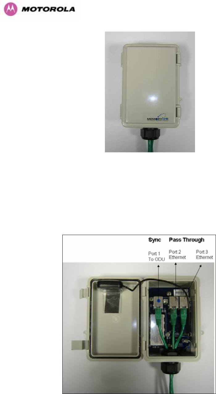
14.2.1 Installing the Recommended GPS Synchronization Kit
The recommended GPS Sync installation kit includes the following:
• GPS Sync Box unit from MemoryLink (see Figure 125), with two attached
terminated Ethernet and Sync cables and cable glands (2) which connect directly
to a PTP 600 Series ODU, and an attached un-terminated Ethernet cable.
• Mounting bracket and mounting bracket screws
• Outdoor rated UV resistant cable tie
• GPS Sync Box User Manual.
In addition to the hardware mentioned above, it is recommended to have an appropriate
lightning protection (ALPU-ORT in Section 16).
27 TDD Synchronization assumes that the user is familiar with network planning issues. For simple
networks, it is advisable not to use the “Expert Mode” and rely on the configuration wizard.
212
Figure 125 - GPS Synchronization Unit
NOTE: Refer to GPS Sync Box User manual for al the details on the lengths of all the cables
used to connect the GPS Sync Box to the ODU.
Figure 126 shows the connections in the GPS Sync Box unit and Figure 127 is a diagram that
shows how to connect the GPS Sync box to the ODU and the Lightning protection unit.
Figure 126 - GPS Synchronization Unit Connections
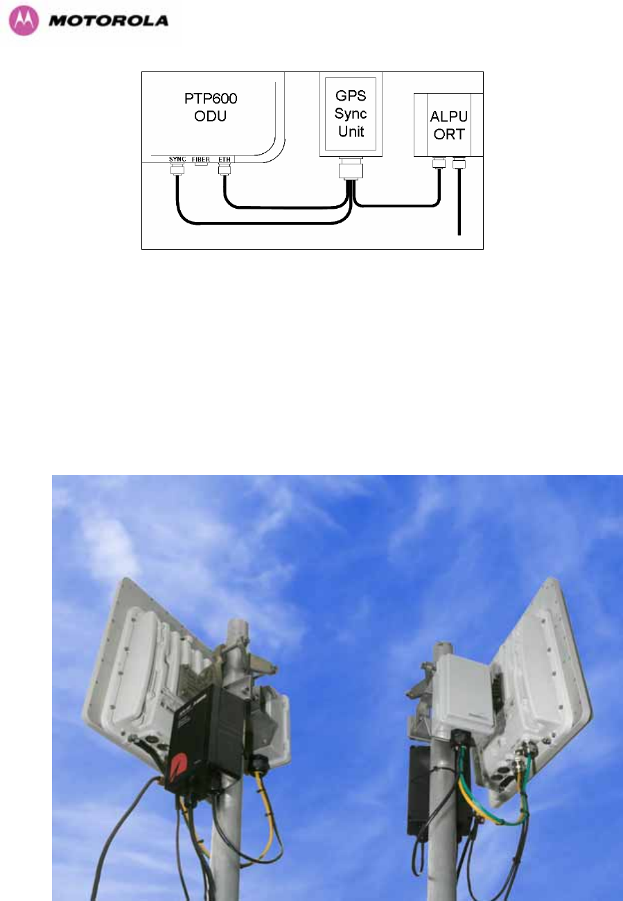
213
Figure 127 - TDD Sync - PTP600 Deployment Diagram
NOTE: Installation details of the GPS Sync Box are described in the GPS Sync Box User
Manual.
Figure 128 shows an example of mast installation using lightning protection and a GPS Sync
Box unit.
Figure 128- GPS Synchronization Unit Complete Installation
214
14.3 Configuring the TDD Synchronization Feature
TDD synchronization is enabled and configured using the install wizard during the installation
process of the link28.
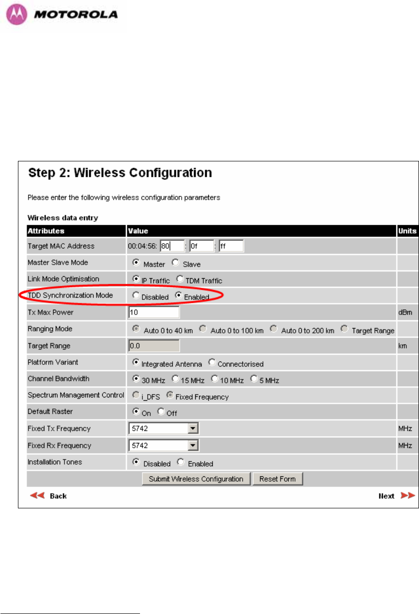
14.3.1 TDD Synchronization Enable
Figure 129 shows how to enable TDD Synchronization.
Figure 129 - Enabling TDD Synchronization Feature
28 TDD synchronisation is not available in regions where radar avoidance is enabled.
215
When TDD Synchronization is enabled, note that:
¾ ‘Ranging Mode’ and ‘Target Range’ controls are disabled on the wireless
configuration page.
¾ ‘Spectrum Management’ Control is forced to ‘Fixed Frequency’ operation only.
14.3.2 TDD Synchronization Configuration Menu
14.3.2.1 TDD Synchronization Configuration - Standard Mode
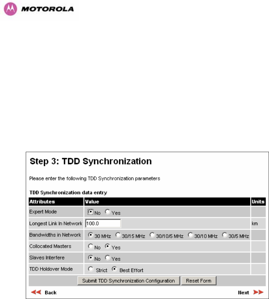
When TDD Synchronization is enabled, there is an extra installation screen (“TDD
Synchronization”) as shown in Figure 130.
Figure 130 - Configuring TDD Synchronization – Screen 1
The TDD Synchronization screen provides the following controls:
Expert Mode: Select “Yes” to use “Expert Mode”. This is an option recommended only for
experienced network and cell planners and is outside the scope of this document (see Figure
132 for parameters required to configure in this mode). If “Expert Mode” is not selected, then
the user is required to enter some basic information to allow the software to calculate the best
values for Frame Duration and Burst Duration.

216
Longest Link in Network: Default value is 100 kms (60 miles). It is the distance of the
longest link in the network (maximum is 200 kms or 120 miles).
Bandwidths in Network: It is very likely that there will be several different channel
bandwidths in a given network. Table 30 gives a list of bandwidth combinations that permit
synchronization without gross loss of efficiency. Note that depending on the channel
bandwidth size, only subsets of Table 30 will be shown in the configuration wizard screen.
Bandwidth
Combination
(MHz)
30
30/5
30/10
5/10/30
15/30
15
10/15
5/10
10
5
Table 30 - Common Burst Durations
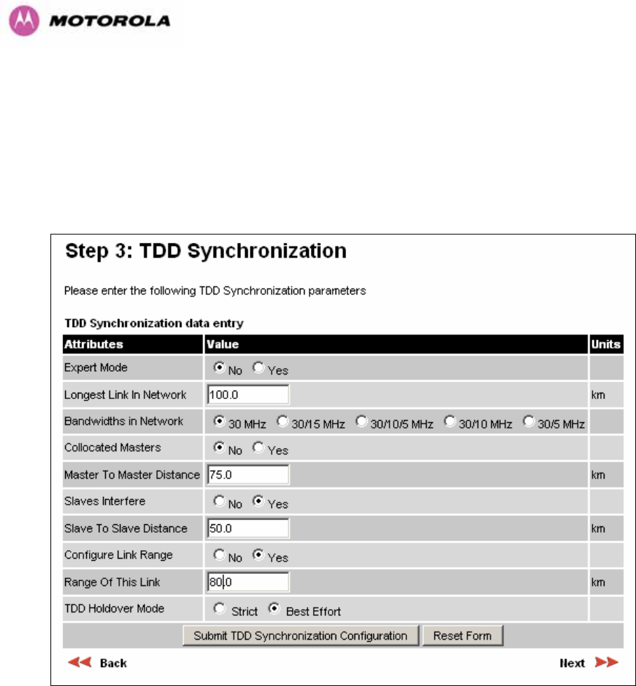
Collocated Masters: choose “Yes” to indicate that ODUs are collocated on the same mast. If
the option “No” is selected, then the control below is displayed (see Figure 131):
Master to Master Range: Maximum range is 200 Kms (120 miles). It is the longest
distance over which two masters can interfere.
Slave Interfere: Select “Yes” to indicate that a Slave ODU interferes. If the option “No” is
selected, then the control below is displayed (see Figure 131 ):
Slave to Slave Range: Maximum range is 200 Kms (120 miles). It is the longest
distance over which two slaves can interfere.
Configure Link Range: Choose “yes” to enter the range of the link in control below: Note
that Link Range MUST be less or equal to “Longest Link in Network”. In some networks,
throughput can be increased by entering the exact range of each link in the wizard.
217
TDD Holdover Mode: Two values: “Strict” and “Best Effort”. If a PTP 600 master ODU is
configured for a TDD Holdover Mode set to “Strict”, then it will not transmit when
synchronization is lost. On the other hand, a link configured for TDD Holdover Mode set to
“Best Effort” will synchronize when a reference signal is available, but will otherwise use best
efforts to operate in unsynchronized fashion.
Figure 131 - Configuring TDD Synchronization Feature - Screen 2
218
WARNING: the values entered for the controls in Figure 131 MUST be the same for all the
links in the network, except for the attribute “Range of This Link” which can be entered exactly
for better performance.
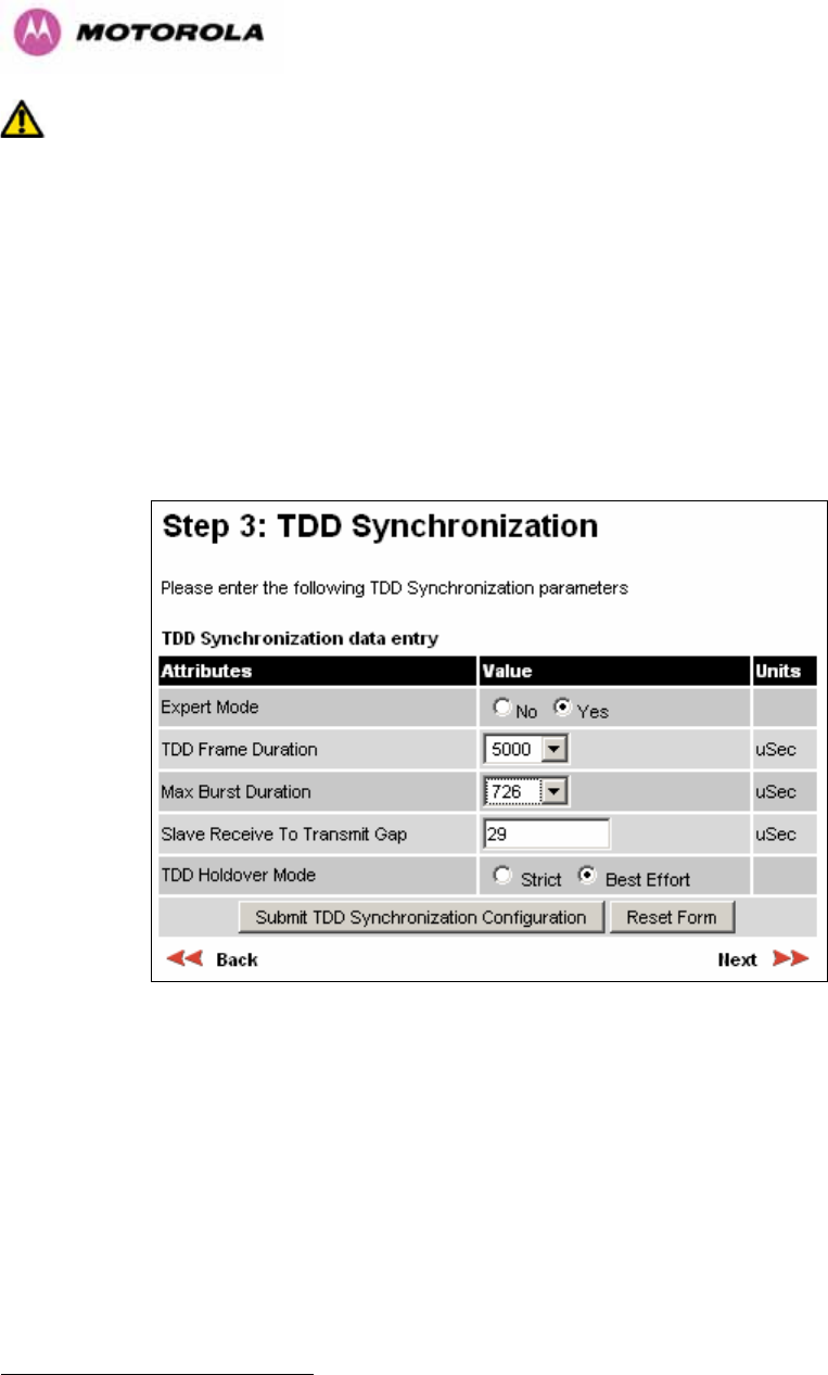
14.3.2.2 TDD Synchronization Configuration – Expert Mode
When “Expert Mode” is selected, the user is required to configure the parameters29 shown in
Figure 132. As mentioned previously, this is outside the score of this document. However, this
mode can be used as informative to ensure that the values of the parameters are the same
for all the links in the network.
Figure 132 - Configure TDD Synchronization Expert Mode
29 For the non-expert mode, the controls in are automatically filled by the software Figure 132
221
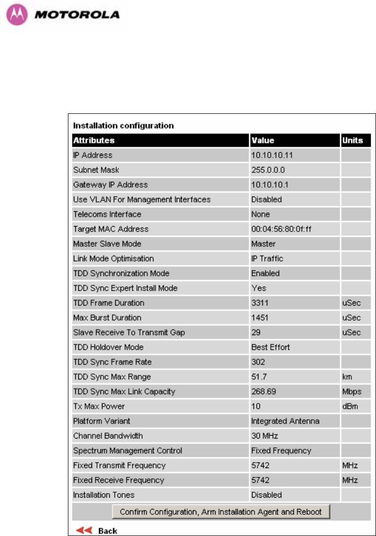
14.3.2.4 Disarm ODU Following TDD Sync Configuration
Figure 136 - Disarm Following TDD Synchronization
WARNING: In a synchronized network, links MUST be configured separately before bringing
the whole network up.
222
15 E1/T1 Installation Guide
15.1 Preparing the PTP 600 Series Bridge E1/T1 Cable
Note: The maximum cable length between the ODU and the customers terminating
equipment is 200m (656 feet) for T1.
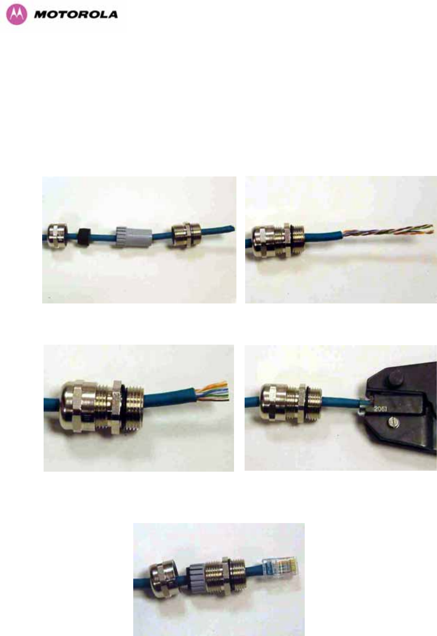
The E1/T1 cable should be assembled to the following instructions:
Step 1: Assemble gland on cable as shown Step 2: Strip the outer insulation
Step 3: Arrange conductors as shown in fig.
A2 and cut to length
Step 4: Insert conductors and crimp
Figure 137 - Completed ODU Connector
223
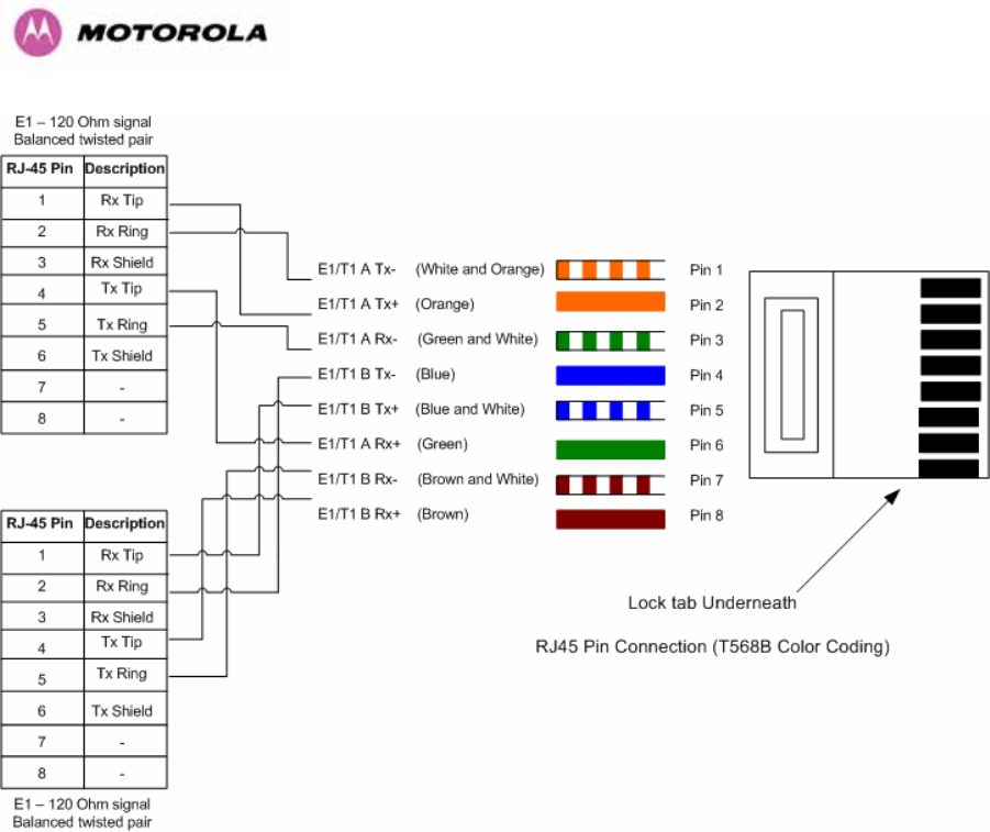
This procedure applies to the ODU termination. The above procedure should be repeated for
the customer equipment end of the cable when the cable is terminated with a RJ45.
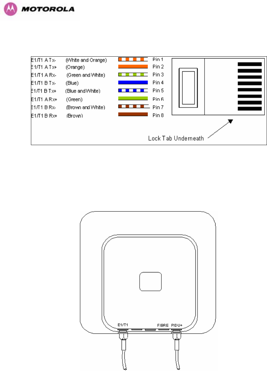
Figure 138 - RJ45 Pin Connection (T568B Color Coding)
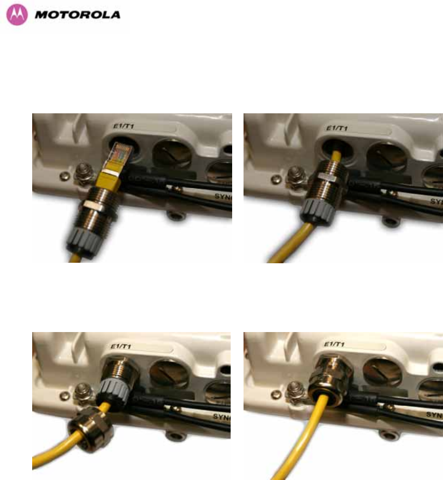
15.2 Making the Connection at the ODU
Looking at the back of the unit with the cable entry at the bottom, the PTP 600 Series Bridge
E1/T1 connection is the first hole on the left (Figure 139) and is labeled E1/T1.
Figure 139 - PIDU Plus and E1-T1 Connection
224
The following procedure describes how connection is made at the ODU. It is often easier to
carry out this procedure on the ground or a suitable surface prior to mounting the ODU.
Ensure no power is connected to the PIDU Plus.
Step 1: Assemble the cable as described in
above
Step 2: Insert the RJ45 connector making sure
that the locking tab snaps home
Step 3: Screw in the body of the weather
proofing gland and tighten
Step 4: Screw on the clamping nut and tighten

225
Should it be necessary to disconnect the
E1/T1 cable at the ODU this can be
achieved by removing the weatherproofing
gland and depressing the RJ45 locking tab
with a small screwdriver as shown in the
opposite photograph.
Figure 140 - Disconnecting the ODU
226
15.3 Routing the Cable
After connecting the cable to the ODU it can be routed and secured using standard cable
routing and securing techniques. When the cable is in place it can then be cut to the desired
length.
15.4 Fitting a Surge Arrestor
If you have opted to fit a Surge Arrestor, it should be installed as described in Section A1.5
“Lightning Protection”
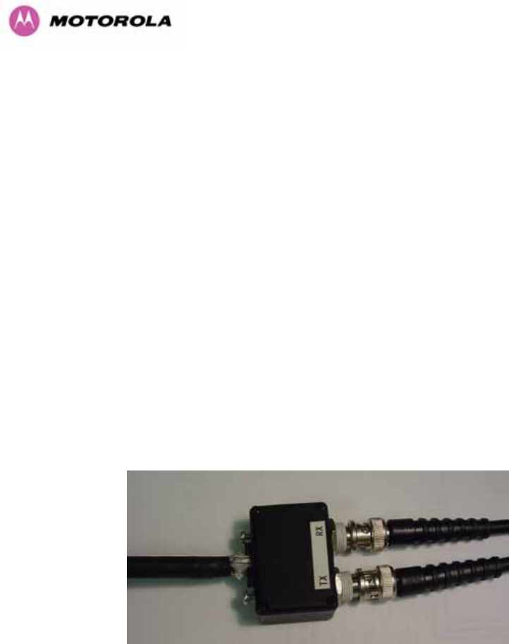
15.5 Customer Cable Termination
The two channels can be separated by means of a patch panel which may include Baluns for
transmission over 75 Ohm co-axial unbalanced lines. Such equipment should conform to the
requirements of C.C.I.T.T. G703. An example of a Balun is shown below. It allows the
transmit and receive data carried over a 75 Ohm cable to be converted to a balanced form for
transmission over a 120 Ohm signal balanced twisted pair.
Figure 141 - Example of a Balun
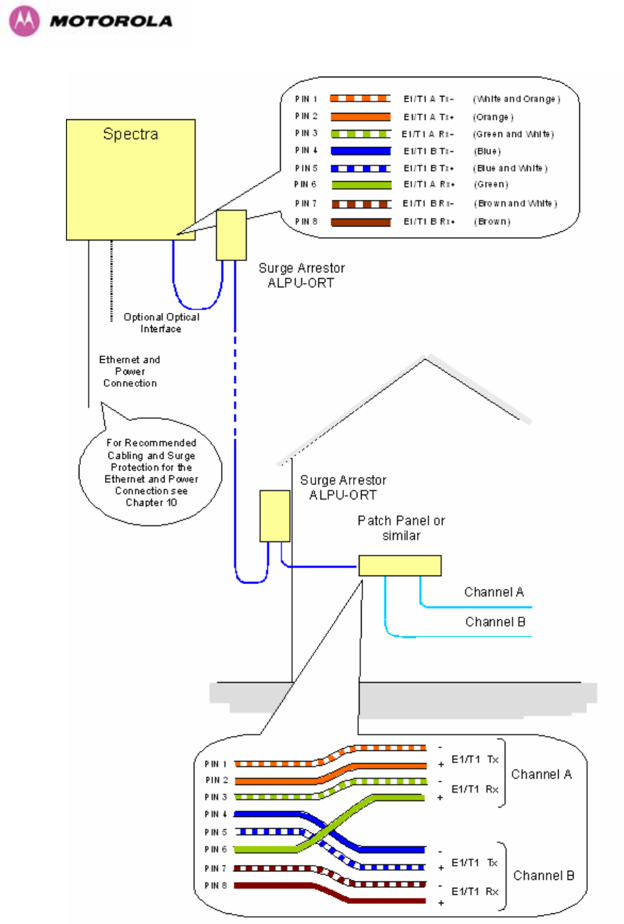
227
Figure 142 - Diagrammatically Showing the E1-T1 Connections
228
Figure 143 - Two E1-T1-120 Ohms signal Balanced to PTP600 Interface

229
16 Lightning Protection
16.1 Overview
Section 11 in the main body of this manual contains the requirements for the Motorola PTP
600 Series deployment. This section details the additional requirements for the deployment of
E1/T1.
16.2 Recommended Additional Components for E1/T1 Installation.
The recommended components below are in addition to those listed in Section 11, the extra
components required for the E1/T1 installation are:
• Screened Cat 5 Cable
• Surge Arrestor Units — Transtector type ALPU-ORT, 4 required per link.
(www.transtector.com)
• RJ45 screened connectors
• 8 AWG Grounding Cable
For a description of Zone A and Zone B refer to Section 11.
Zone A Zone B
Earth ODU Mandatory Mandatory
Screen Cable Mandatory Mandatory
Surge Arrestor Unit ALPU-ORT at ODU Mandatory Mandatory
Earth Cable at Building Entry Mandatory Mandatory
Surge Arrestor Unit ALPU-ORT at Building Entry Mandatory Mandatory
Table 31 - Protection Requirements
230
Figure 144 - Typical Mast Installation with the addition of the E1-T1 cable
231
Note: There may be a local regulatory requirement to cross bond the CAT 5 drop cable at
regular intervals to the mast. This may be as frequent as every 10 meters (33 feet).
Figure 145 - Wall Installation with the addition of E1-T1 cable

232
16.3 Surge Arrestor Wiring
An Andrew Grounding Kit and Surge Arrestor Unit must be located at the ODU and reliably
grounded as shown in Figure 109. There may also be a regulatory requirement to crossbond
the screened CAT-5 at regular intervals up the mast. Refer to local regulatory requirements
for further details.
A second Surge Arrestor Unit should be mounted at the building entry point and must be
grounded.
The termination of the CAT-5 Cable into the Surge Arrestor Unit is illustrated in Table 32,
Table 33 and Figure 146. The screen from the cable must be terminated into the ground
terminal within the unit to ensure the continuity of the screen. Earth Sleeving should be used
to cover the shield ground connection to prevent internal shorting within the unit.
Terminal Identification Conductor RJ45 Pin
CON3 Pin 1 Orange/White 1
CON3 Pin 2 Orange 2
CON3 Pin 3 Green/White 3
CON3 Pin 6 Green 6
CON1 Pin 4 Blue 4
CON1 Pin 5 Blue/White 5
CON1 Pin 7 Brown/White 7
CON1 Pin 8 Brown 8
Table 32 - Surge Arrestor ALPU-ORT Cable 1 Termination
Terminal Identification Conductor RJ45 Pin
CON4 Pin 1 Orange/White 1
CON4 Pin 2 Orange 2
CON4 Pin 3 Green/White 3
CON4 Pin 6 Green 6
CON2 Pin 4 Blue 4
CON2 Pin 5 Blue/White 5
CON2 Pin 7 Brown/White 7
CON2 Pin 8 Brown 8
Table 33 - Surge Arrestor ALPU-ORT Cable 2 Termination
233
Figure 146 - Surge Arrestor ALPU-ORT Connection Illustration
234
16.4 Testing Your Installation
If you have followed the above instructions you will have wired your systems to the following
diagram:
Figure 147 - Simplified Circuit Diagram (Only One Transtector Shown For Clarity)
16.4.1 Pre-Power Testing
Before connecting your E1/T1 source, check the following resistances:
1. Check the cable resistance between pins 3 & 6 (Green/White & Green) and 7 & 8
(Brown/White & Brown). Check against Table 34 column 2.
2. Check the cable resistance between pins 1 & 2 (Orange/White & Orange) and 4 & 5
(Blue & Blue/White). Check against Table 34 column 3.

235
CAT-5 Length (Meters) Resistance between pins
3 & 6 and pins 7 & 8
(ohms)
Resistance between pins
1 & 2 and pins 4 & 5
(ohms)
0 0.8 1.3
10 2.5 3.0
20 4.2 4.7
30 5.9 6.4
40 7.6 8.2
50 9.3 9.8
60 11.0 11.5
70 12.7 13.2
80 14.4 14.9
90 16.1 18.2
100 17.8 18.3
Table 34 - Resistance Table Referenced To the E1/T1 Source
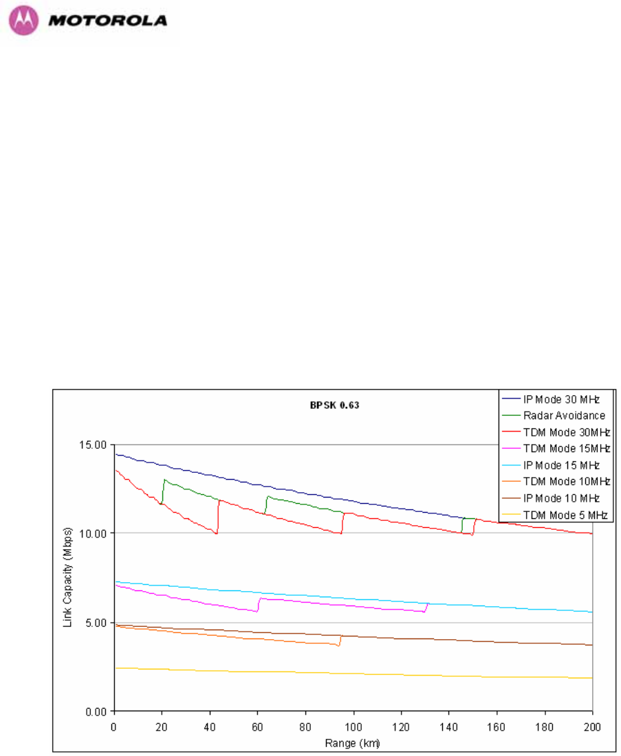
236
17 Data Rate Calculations
To aid the calculation of data rate throughput, the following plots of throughput verses link
range have been produced for all the PTP 600 Series modulation modes, assuming the units
are connected using Gigabit Ethernet.
Aggregate data rate capacity can be calculated using four key system parameters:
• Receive modulation mode
• Transmit modulation mode
• Range Between the two wireless units
• Wireless link mode (IP or TDM)
Using these parameters the Receive and Transmit data rates can be looked up using the
plots Figure 148 through Figure 160.
Figure 148 - BPSK 0.63 Single Payload
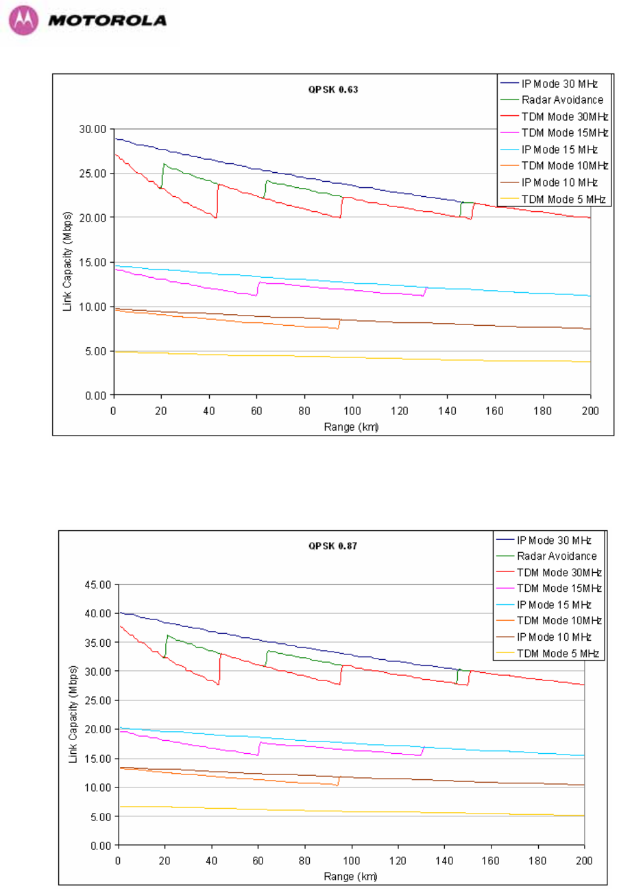
237
Figure 149 - QPSK 0.63 Single Payload
Figure 150 - QPSK 0.87 Single Payload
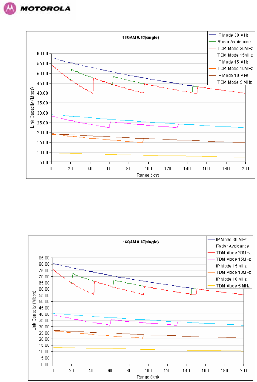
238
Figure 151 - 16 QAM 0.63 Single Payload
Figure 152 - 16 QAM 0.87 Single Payload
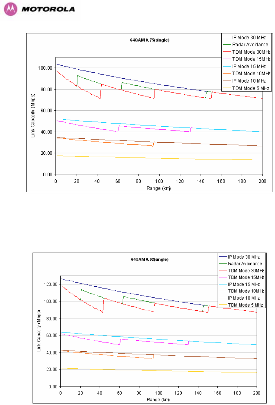
239
Figure 153 - 64 QAM 0.75 Single Payload
Figure 154 - 64 QAM 0.92 Single Payload
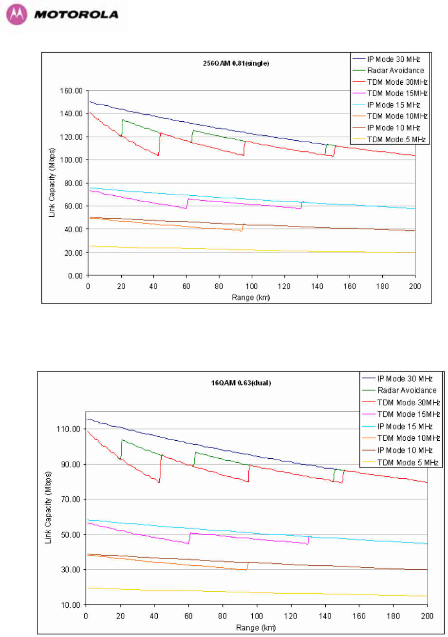
240
Figure 155 - 256 QAM 0.81 Single Payload
Figure 156 - 16 QAM 0.63 Dual Payload
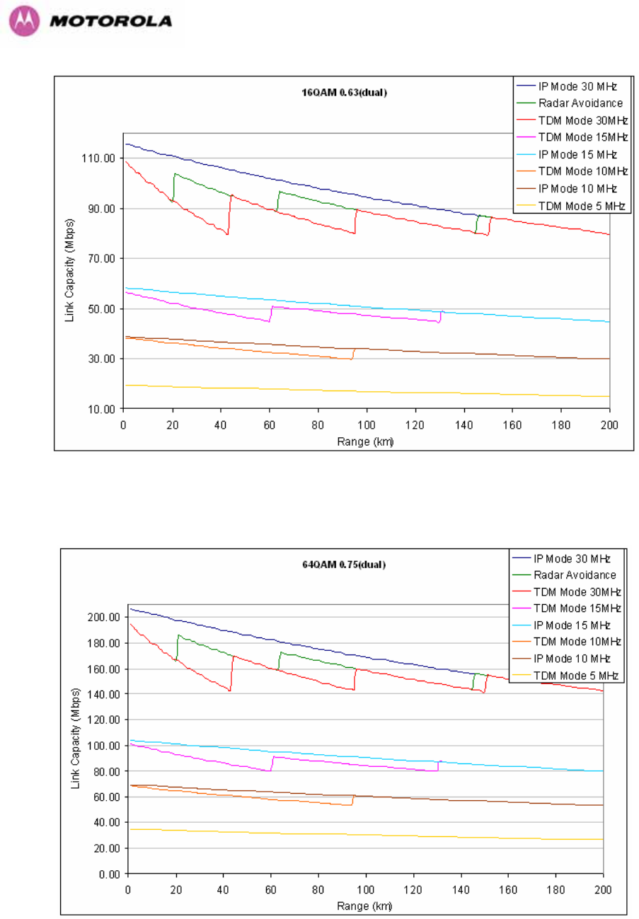
241
Figure 157 - 16 QAM 0.87 Dual Payload
Figure 158 - 64 QAM 0.75 Dual Payload
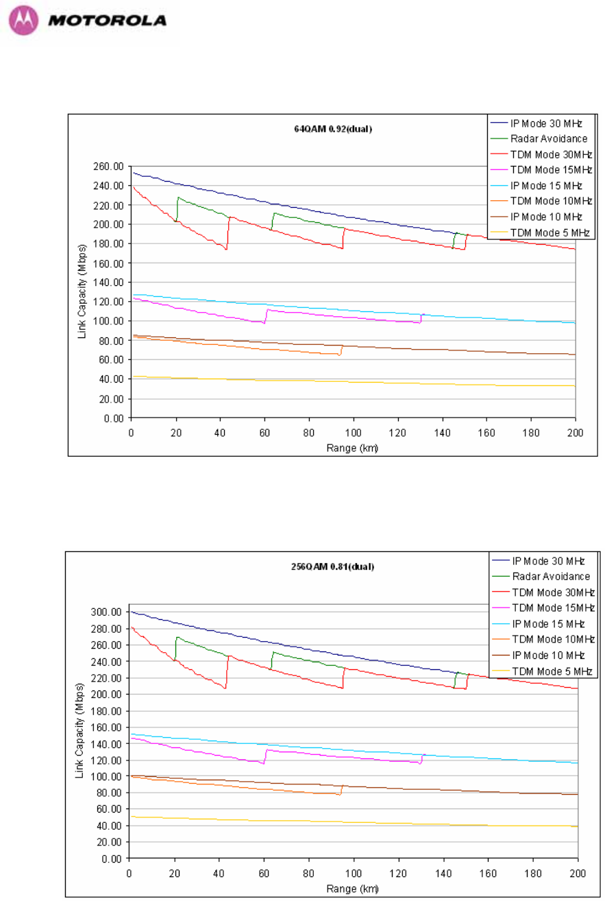
242
Figure 159 - 64 QAM 0.92 Dual Payload
Figure 160 - 256 QAM 0.81 Dual Payload

243
18 AES Encryption Upgrade
The Motorola PTP 600 Series bridges support link encryption using the NIST approved
Advanced Encryption Standard, HFIPS-197UTH. This standard specifies AES (Rijndael) as a
FIPS-approved symmetric encryption algorithm that may be used by U.S. Government
organizations (and others) to protect sensitive information.
Link Encryption is not available in the standard PTP 600 Series system. A license key to
enable link encryption can be purchased from your Motorola Point-to-Point Distributor or
Solutions Provider. AES can be activated on receipt of the activation on the Motorola
Systems Support Page.
There are two levels of encryption that are available to purchase:
• 128-bit
• 128 and 256-bit
Option 1 allows the user to encrypt all traffic sent over the wireless link using 128-bit
encryption. Option 2 allows the user to encrypt traffic using either 128 or 256-bit encryption.
The configuration process for both encryption variants is identical except for the selection of
algorithm. The following configuration example is for a 256-bit encryption key.
18.1 Configuring Link Encryption
After purchasing AES encryption for the PTP 600 Series wireless link, two new license keys
will be issued, one for each end of the wireless link. The following configuration process gives
a step by step guide to enabling AES link encryption on a PTP 600 Series bridge.
18.2 Configuring Link Encryption
After purchasing AES encryption for the PTP 600 Series wireless link, two new license keys
will be issued, one for each end of the wireless link. The following configuration process gives
a step by step guide to enabling AES link encryption on a PTP 600 Series bridge.
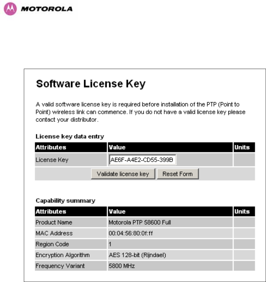
244
18.2.1 License Keys
The first step when configuring link encryption is to enter the new license keys in both 600
Series wireless units.
Figure 161 – AES Software License Key Data Entry
Figure 161 shows the license key data entry screen. This screen can only be accessed by the
system administrator. If you do not have access to the PTP 600 Series system administration
pages then please contact your designated system administrator.
It must be noted that configuring link encryption will necessitate a 600 Series bridge service
outage. Therefore it is recommended that the configuration process be scheduled during an
appropriate period of low link utilization. Motorola recommends the following process for
entering new license keys and minimizing service outage.
1. Open two browsers, one for each end of the link
2. Navigate to the ‘License Key’ data entry page for each end of the link
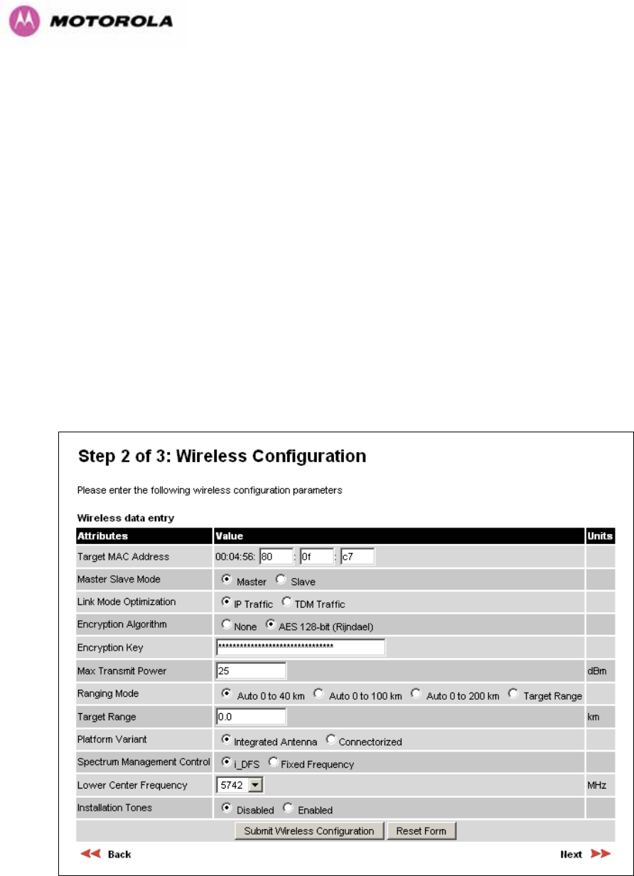
245
3. Enter the license keys and click the ‘Validate license key’ button at each end of the link.
This will allow the software to validate the license key prior to the system reset. (DO NOT
CLICK ARE YOU SURE POPUP DIALOG)
4. When both license keys have been successfully validated confirm the reboot for both
ends of the link. The software is designed to allow five seconds so that a user can
command both ends of the link to reset before the wireless link drops.
5. The link will automatically re-establish.
18.2.2 Encryption Mode and Key
Entering the license keys only does not initialize AES link encryption. Link encryption can only
be enabled via the Configuration or Installation Wizard pages. Motorola recommends that the
Configuration page Figure 162 be used to configure AES link encryption.
Figure 162 – AES Configuration Data Entry Page
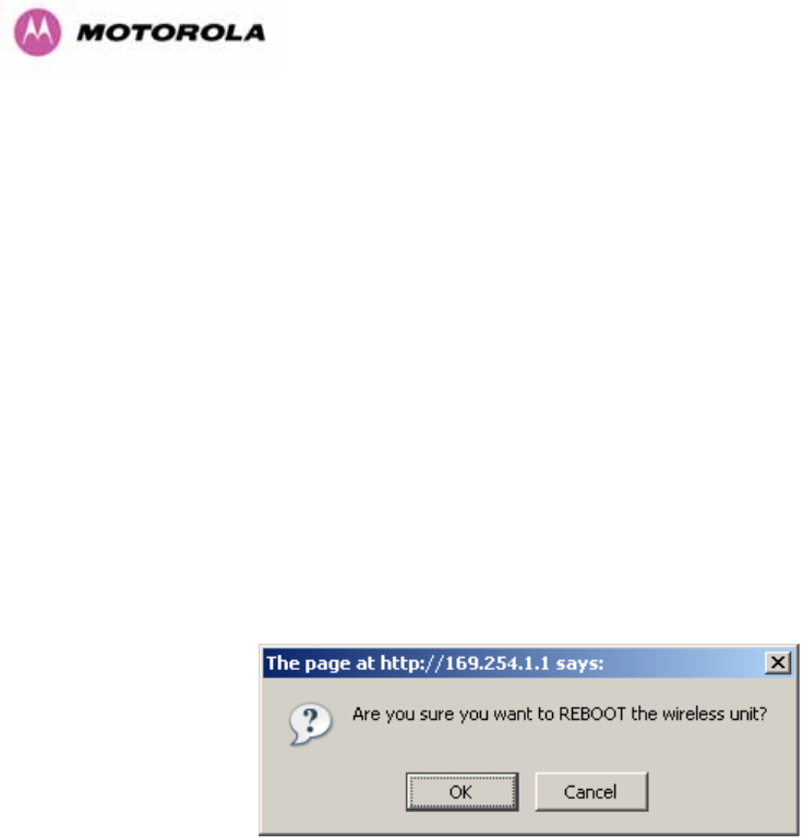
246
Motorola recommends the following process for entering AES link encryption configuration:-
1. Open two browsers, one for each end of the link
2. Navigate to the ‘Configuration’ data entry page for each end of the link
3. At both ends of the link select the ‘AES (Rijndael)’ Encryption Algorithm required.
4. At both ends of the link enter ether an 128-bit or 256-bit encryption key. Note the key
consists of 32/64 case insensitive hexadecimal characters. The same Key must be
entered at both ends of the link. Failure to enter the same key will cause the link to fail.
5. Submit configuration on both ends of the link, but do not reboot.
6. Reboot both ends of the link Figure 163. The software is designed to allow five seconds
so that a user can command both ends of the link to reboot before the wireless link drops.
Figure 163 - Configuration Reboot Screen

247
18.3 Wireless Link Encryption FAQ
18.3.1 Encryption data entry fields are not available
Check that the correct license key has been inserted into the unit. The current license key is
displayed on the ‘License Key’ data entry page.
18.3.2 Link fails to bridge packets after enabling link encryption
If the wireless link status on the status web page indicates that the link is ‘Searching’, and you
can browse to the local end of the link but not to the remote end, then check that the same
encryption algorithm and key have been entered at both ends of the link. Failure to enter the
same algorithm and key will result in received packets not being decrypted correctly.
18.3.3 Loss of AES following downgrade
When downgrading (using Recovery software image 05-01 onwards) to an earlier version of
software that does not support AES, the unit will indicate that the region code is invalid. The
user will be required to re-install correct software (supplied when AES key was activated) and
reboot the unit.

248
19 Legal and Regulatory Notices
19.1 Important Note on Modifications
Intentional or unintentional changes or modifications to the equipment must not be made
unless under the express consent of the party responsible for compliance. Any such
modifications could void the user’s authority to operate the equipment and will void the
manufacturer’s warranty.
19.2 National and Regional Regulatory Notices – 5.8 GHz variant
19.2.1 U.S. Federal Communication Commission (FCC) and Industry Canada (IC) Notification
This system has achieved Type Approval in various countries around the world. This means
that the system has been tested against various local technical regulations and found to
comply. The frequency band in which the system operates is ‘unlicensed’ and the system is
allowed to be used provided it does not cause interference. Further, it is not guaranteed
protection against interference from other products and installations.
This device complies with part 15 of the US FCC Rules and Regulations and with RSS-210 of
Industry Canada. Operation is subject to the following two conditions: (1) This device may
not cause harmful interference, and (2) This device must accept any interference received,
including interference that may cause undesired operation. In Canada, users should be
cautioned to take note that high power radars are allocated as primary users (meaning they
have priority) of 5250 – 5350 MHz and 5650 – 5850 MHz and these radars could cause
interference and/or damage to license-exempt local area networks (LELAN).
This equipment has been tested and found to comply with the limits for a Class B digital
device, pursuant to Part 15 of the US FCC Rules and with RSS-210 of Industry Canada.
These limits are designed to provide reasonable protection against harmful interference in a
residential installation. This equipment generates, uses, and can radiate radio-frequency
energy and, if not installed and used in accordance with these instructions, may cause
harmful interference to radio communications. If this equipment does cause harmful
interference to radio or television reception, which can be determined by turning the
equipment on and off, the user is encouraged to correct the interference by one or more of
the following measures:
• Increase the separation between the affected equipment and the unit;
• Connect the affected equipment to a power outlet on a different circuit from that which the
receiver is connected to;
• Consult the dealer and/or experienced radio/TV technician for help.
• FCC IDs and Industry Canada Certification Numbers are listed in Table 35

249
Table 35 - US FCC IDs and Industry Canada certification numbers
Where necessary, the end user is responsible for obtaining any National licenses required to
operate this product and these must be obtained before using the product in any particular
country. Contact the appropriate national administrations for details on the conditions of use
for the bands in question and any exceptions that might apply. Also see www.ero.dk for
further information.
19.2.2 European Union Notification
The 5.8 GHz connectorized product is a two-way radio transceiver suitable for use in
Broadband Wireless Access System (WAS), Radio Local Area Network (RLAN), or Fixed
Wireless Access (FWA) systems. It is a Class 2 device and uses operating frequencies that
are not harmonized throughout the EU member states. The operator is responsible for
obtaining any national licenses required to operate this product and these must be obtained
before using the product in any particular country.
This equipment complies with the essential requirements for the EU R&TTE Directive 1999/5/EC.
The use of 5.8GHz for Point to Point radio links is not harmonized across the EU and currently the
product may only be deployed in the UK and Eire (IRL). However, the regulatory situation in Europe is
changing and the radio spectrum may become available in other countries in the near future.
This equipment is marked
to show compliance with the European R&TTE directive 1999/5/EC.

250
The relevant Declaration of Conformity can be found at www.motorola.com/ptp
European Union (EU) Waste of Electrical and Electronic Equipment (WEEE) directive
The European Union's WEEE directive requires that products sold into EU countries must
have the crossed out trash bin label on the product (or the package in some cases).
As defined by the WEEE directive, this cross-out trash bin label means that customers and
end-users in EU countries should not dispose of electronic and electrical equipment or
accessories in household waste. Customers or end-users in EU countries should contact their
local equipment supplier representative or service center for information about the waste
collection system in their country.
19.2.3 UK Notification
The 5.8 GHz connectorized product has been notified for operation in the UK, and when
operated in accordance with instructions for use it is compliant with UK Interface Requirement
IR2007. For UK use, installations must conform to the requirements of IR2007 in terms of
EIRP spectral density against elevation profile above the local horizon in order to protect
Fixed Satellite Services. The frequency range 5795-5815 MHz is assigned to Road Transport
& Traffic Telematics (RTTT) in the U.K. and shall not be used by FWA systems in order to
protect RTTT devices. UK Interface Requirement IR2007 specifies that radiolocation services
shall be protected by a Dynamic Frequency Selection (DFS) mechanism to prevent co-
channel operation in the presence of radar signals.
Important Note
This equipment operates as a secondary application, so it has no rights against harmful
interference, even if generated by similar equipment, and cannot cause harmful interference
on systems operating as primary applications.

251
19.3 National and Regional Regulatory Notices – 5.4 GHz Variant
19.3.1 U.S. Federal Communication Commission (FCC) and Industry Canada (IC) Notification30
This device complies with part 15.407 of the US FCC Rules and Regulations and with RSS-
210 Issue 7 of Industry Canada. Operation is subject to the following two conditions: (1) This
device may not cause harmful interference, and (2) This device must accept any interference
received, including interference that may cause undesired operation. In Canada, users should
be cautioned to take note that high power radars are allocated as primary users (meaning
they have priority) of 5250 – 5350 MHz and 5650 – 5850 MHz and these radars could cause
interference and/or damage to license-exempt local area networks (LELAN).
This equipment has been tested and found to comply with the limits for a Class B digital
device, pursuant to Part 15E of the US FCC Rules and with RSS-210 Issue 7 of Industry
Canada. These limits are designed to provide reasonable protection against harmful
interference in a residential installation. This equipment generates, uses, and can radiate
radio-frequency energy and, if not installed and used in accordance with these instructions,
may cause harmful interference to radio communications. If this equipment does cause
harmful interference to radio or television reception, which can be determined by turning the
equipment on and off, the user is encouraged to correct the interference by one or more of
the following measures:
• Increase the separation between the affected equipment and the unit;
• Connect the affected equipment to a power outlet on a different circuit from that which the
receiver is connected to;
• Consult the dealer and/or experienced radio/TV technician for help.
• FCC IDs and Industry Canada Certification Numbers are listed in Table 36
Table 36 - US FCC IDs and Industry Canada certification numbers
30 FCC and IC certification approval applies ONLY to INTEGRATED variant.

252
Where necessary, the end user is responsible for obtaining any National licenses required to
operate this product and these must be obtained before using the product in any particular
country. Contact the appropriate national administrations for details on the conditions of use
for the bands in question and any exceptions that might apply. Also see www.eor.dk for
further information.
19.3.2 European Union Notification
The 5.4 GHz product is a two-way radio transceiver suitable for use in Broadband Wireless
Access System (WAS), Radio Local Area Network (RLAN), or Fixed Wireless Access (FWA)
systems. It is a Class 2 device and uses operating frequencies that are not harmonized
throughout the EU member states. The operator is responsible for obtaining any national
licenses required to operate this product and these must be obtained before using the product
in any particular country.
This equipment complies with the essential requirements for the EU R&TTE Directive
1999/5/EC.
The use of 5.4GHz for Point to Point radio links is harmonized across the EU.
This equipment is marked
to show compliance with the European R&TTE directive 1999/5/EC.

253
The relevant Declaration of Conformity can be found at www.motorola.com
European Union (EU) Waste of Electrical and Electronic Equipment (WEEE) directive
The European Union's WEEE directive requires that products sold into EU countries must
have the crossed out trash bin label on the product (or the package in some cases).
As defined by the WEEE directive, this cross-out trash bin label means that customers and
end-users in EU countries should not dispose of electronic and electrical equipment or
accessories in household waste. Customers or end-users in EU countries should contact their
local equipment supplier representative or service center for information about the waste
collection system in their country.

254
19.4 National and Regional Regulatory Notices – 2.5 GHz Variant
19.4.1 U.S. Federal Communication Commission (FCC) Notification
This device complies with Part 27 of the US FCC Rules and Regulations. Use of this product
is limited to operators holding Licenses for the specific operating channels.
This equipment has been tested and found to comply with the limits for a Class B digital
device, pursuant to Part 15E of the US FCC Rules. These limits are designed to provide
reasonable protection against harmful interference in a residential installation. This
equipment generates, uses, and can radiate radio-frequency energy and, if not installed and
used in accordance with these instructions, may cause harmful interference to radio
communications. If this equipment does cause harmful interference to radio or television
reception, which can be determined by turning the equipment on and off, the user is
encouraged to correct the interference by one or more of the following measures:
• Increase the separation between the affected equipment and the unit;
• Connect the affected equipment to a power outlet on a different circuit from that which the
receiver is connected to;
• Consult the dealer and/or experienced radio/TV technician for help.
• FCC IDs Certification Numbers are listed in Table 36
Table 37 - US FCC IDs and Industry Canada certification numbers
Where necessary, the end user is responsible for obtaining any National licenses required to
operate this product and these must be obtained before using the product in any particular
country. Contact the appropriate national administrations for details on the conditions of use
for the bands in question and any exceptions that might apply.

255
19.5 Exposure
See Preventing Overexposure to RF on Page 26.
19.6 Legal Notices
19.6.1 Software License Terms and Conditions
ONLY OPEN THE PACKAGE, OR USE THE SOFTWARE AND RELATED PRODUCT IF
YOU ACCEPT THE TERMS OF THIS LICENSE. BY BREAKING THE SEAL ON THIS DISK
KIT / CDROM, OR IF YOU USE THE SOFTWARE OR RELATED PRODUCT, YOU ACCEPT
THE TERMS OF THIS LICENSE AGREEMENT. IF YOU DO NOT AGREE TO THESE
TERMS, DO NOT USE THE SOFTWARE OR RELATED PRODUCT; INSTEAD, RETURN
THE SOFTWARE TO PLACE OF PURCHASE FOR A FULL REFUND. THE FOLLOWING
AGREEMENT IS A LEGAL AGREEMENT BETWEEN YOU (EITHER AN INDIVIDUAL OR
ENTITY), AND MOTOROLA, INC. (FOR ITSELF AND ITS LICENSORS). THE RIGHT TO
USE THIS PRODUCT IS LICENSED ONLY ON THE CONDITION THAT YOU AGREE TO
THE FOLLOWING TERMS.
Now, therefore, in consideration of the promises and mutual obligations contained herein, and
for other good and valuable consideration, the receipt and sufficiency of which are hereby
mutually acknowledged, you and Motorola agree as follows:
Grant of License. Subject to the following terms and conditions, Motorola, Inc., grants to you
a personal, revocable, non-assignable, non-transferable, non-exclusive and limited license to
use on a single piece of equipment only one copy of the software contained on this disk
(which may have been pre-loaded on the equipment)(Software). You may make two copies of
the Software, but only for backup, archival, or disaster recovery purposes. On any copy you
make of the Software, you must reproduce and include the copyright and other proprietary
rights notice contained on the copy we have furnished you of the Software.

256
Ownership. Motorola (or its supplier) retains all title, ownership and intellectual property
rights to the Software and any copies, including translations, compilations, derivative works
(including images) partial copies and portions of updated works. The Software is Motorola’s
(or its supplier's) confidential proprietary information. This Software License Agreement does
not convey to you any interest in or to the Software, but only a limited right of use. You agree
not to disclose it or make it available to anyone without Motorola’s written authorization. You
will exercise no less than reasonable care to protect the Software from unauthorized
disclosure. You agree not to disassemble, decompile or reverse engineer, or create derivative
works of the Software, except and only to the extent that such activity is expressly permitted
by applicable law.
Termination. This License is effective until terminated. This License will terminate
immediately without notice from Motorola or judicial resolution if you fail to comply with any
provision of this License. Upon such termination you must destroy the Software, all
accompanying written materials and all copies thereof, and the sections entitled Limited
Warranty, Limitation of Remedies and Damages, and General will survive any termination.
Limited Warranty. Motorola warrants for a period of ninety (90) days from Motorola’s or its
customer’s shipment of the Software to you that (i) the disk(s) on which the Software is
recorded will be free from defects in materials and workmanship under normal use and (ii) the
Software, under normal use, will perform substantially in accordance with Motorola’s
published specifications for that release level of the Software. The written materials are
provided "AS IS" and without warranty of any kind. Motorola's entire liability and your sole
and exclusive remedy for any breach of the foregoing limited warranty will be, at Motorola's
option, replacement of the disk(s), provision of downloadable patch or replacement code, or
refund of the unused portion of your bargained for contractual benefit up to the amount paid
for this Software License.

257
THIS LIMITED WARRANTY IS THE ONLY WARRANTY PROVIDED BY MOTOROLA, AND
MOTOROLA AND ITS LICENSORS EXPRESSLY DISCLAIM ALL OTHER WARRANTIES,
EITHER EXPRESS OF IMPLIED, INCLUDING BUT NOT LIMITED TO IMPLIED
WARRANTIES OF MERCHANTABILITY AND FITNESS FOR A PARTICULAR PURPOSE
AND NONINFRINGEMENT. MOTOROLA DOES NOT WARRANT THAT THE OPERATION
OF THE SOFTWARE WILL BE UNINTERRUPTED OR ERROR-FREE, OR THAT DEFECTS
IN THE SOFTWARE WILL BE CORRECTED. NO ORAL OR WRITTEN
REPRESENTATIONS MADE BY MOTOROLA OR AN AGENT THEREOF SHALL CREATE
A WARRANTY OR IN ANY WAY INCREASE THE SCOPE OF THIS WARRANTY.
MOTOROLA DOES NOT WARRANT ANY SOFTWARE THAT HAS BEEN OPERATED IN
EXCESS OF SPECIFICATIONS, DAMAGED, MISUSED, NEGLECTED, OR IMPROPERLY
INSTALLED. BECAUSE SOME JURISDICTIONS DO NOT ALLOW THE EXCLUSION OR
LIMITATION OF IMPLIED WARRANTIES, THE ABOVE LIMITATIONS MAY NOT APPLY TO
YOU.
Limitation of Remedies and Damages. Regardless of whether any remedy set forth herein
fails of its essential purpose, IN NO EVENT SHALL MOTOROLA OR ANY OF THE
LICENSORS, DIRECTORS, OFFICERS, EMPLOYEES OR AFFILIATES OF THE
FOREGOING BE LIABLE TO YOU FOR ANY CONSEQUENTIAL, INCIDENTAL, INDIRECT,
SPECIAL OR SIMILAR DAMAGES WHATSOEVER (including, without limitation, damages
for loss of business profits, business interruption, loss of business information and the like),
whether foreseeable or unforeseeable, arising out of the use or inability to use the Software
or accompanying written materials, regardless of the basis of the claim and even if Motorola
or a Motorola representative has been advised of the possibility of such damage. Motorola's
liability to you for direct damages for any cause whatsoever, regardless of the basis of the
form of the action, will be limited to the price paid for the Software that caused the damages.
THIS LIMITATION WILL NOT APPLY IN CASE OF PERSONAL INJURY ONLY WHERE
AND TO THE EXTENT THAT APPLICABLE LAW REQUIRES SUCH LIABILITY. BECAUSE
SOME JURISDICTIONS DO NOT ALLOW THE EXCLUSION OR LIMITATION OF LIABILITY
FOR CONSEQUENTIAL OR INCIDENTAL DAMAGES, THE ABOVE LIMITATION MAY NOT
APPLY TO YOU.
Maintenance and Support. Motorola shall not be responsible for maintenance or support of
the software. By accepting the license granted under this agreement, you agree that
Motorola will be under no obligation to provide any support, maintenance or service in
connection with the Software or any application developed by you. Any maintenance and
support of the Related Product will be provided under the terms of the agreement for the
Related Product.

258
Transfer. In the case of software designed to operate on Motorola equipment, you may not
transfer the Software to another party except: (1) if you are an end-user, when you are
transferring the Software together with the Motorola equipment on which it operates; or 2) if
you are a Motorola licensed distributor, when you are transferring the Software either together
with such Motorola equipment or are transferring the Software as a licensed duly paid for
upgrade, update, patch, new release, enhancement or replacement of a prior version of the
Software. If you are a Motorola licensed distributor, when you are transferring the Software as
permitted herein, you agree to transfer the Software with a license agreement having terms
and conditions no less restrictive than those contained herein. You may transfer all other
Software, not otherwise having an agreed restriction on transfer, to another party. However,
all such transfers of Software are strictly subject to the conditions precedent that the other
party agrees to accept the terms and conditions of this License, and you destroy any copy of
the Software you do not transfer to that party. You may not sublicense or otherwise transfer,
rent or lease the Software without our written consent. You may not transfer the Software in
violation of any laws, regulations, export controls or economic sanctions imposed by the US
Government.
Right to Audit. Motorola shall have the right to audit annually, upon reasonable advance
notice and during normal business hours, your records and accounts to determine
compliance with the terms of this Agreement.
Export Controls. You specifically acknowledge that the software may be subject to United
States and other country export control laws. You shall comply strictly with all requirements
of all applicable export control laws and regulations with respect to all such software and
materials.
US Government Users. If you are a US Government user, then the Software is provided
with "RESTRICTED RIGHTS" as set forth in subparagraphs (c)(1) and (2) of the Commercial
Computer Software-Restricted Rights clause at FAR 52 227-19 or subparagraph (c)(1)(ii) of
the Rights in Technical Data and Computer Software clause at DFARS 252.227-7013, as
applicable.

259
Disputes. You and Motorola hereby agree that any dispute, controversy or claim, except for
any dispute, controversy or claim involving intellectual property, prior to initiation of any formal
legal process, will be submitted for non-binding mediation, prior to initiation of any formal legal
process. Cost of mediation will be shared equally. Nothing in this Section will prevent either
party from resorting to judicial proceedings, if (i) good faith efforts to resolve the dispute under
these procedures have been unsuccessful, (ii) the dispute, claim or controversy involves
intellectual property, or (iii) interim relief from a court is necessary to prevent serious and
irreparable injury to that party or to others.
General. Illinois law governs this license. The terms of this license are supplemental to any
written agreement executed by both parties regarding this subject and the Software Motorola
is to license you under it, and supersedes all previous oral or written communications
between us regarding the subject except for such executed agreement. It may not be
modified or waived except in writing and signed by an officer or other authorized
representative of each party. If any provision is held invalid, all other provisions shall remain
valid, unless such invalidity would frustrate the purpose of our agreement. The failure of either
party to enforce any rights granted hereunder or to take action against the other party in the
event of any breach hereunder shall not be deemed a waiver by that party as to subsequent
enforcement of rights or subsequent action in the event of future breaches.
19.6.2 Hardware Warranty in U.S.
Motorola U.S. offers a warranty covering a period of one year from the date of purchase by
the customer. If a product is found defective during the warranty period, Motorola will repair
or replace the product with the same or a similar model, which may be a reconditioned unit,
without charge for parts or labor.
19.6.3 Limit of Liability
IN NO EVENT SHALL MOTOROLA BE LIABLE TO YOU OR ANY OTHER PARTY FOR ANY
DIRECT, INDIRECT, GENERAL, SPECIAL, INCIDENTAL, CONSEQUENTIAL, EXEMPLARY
OR OTHER DAMAGE ARISING OUT OF THE USE OR INABILITY TO USE THE PRODUCT
(INCLUDING, WITHOUT LIMITATION, DAMAGES FOR LOSS OF BUSINESS PROFITS,
BUSINESS INTERRUPTION, LOSS OF BUSINESS INFORMATION OR ANY OTHER
PECUNIARY LOSS, OR FROM ANY BREACH OF WARRANTY, EVEN IF MOTOROLA HAS
BEEN ADVISED OF THE POSSIBILITY OF SUCH DAMAGES. (Some states do not allow
the exclusion or limitation of incidental or consequential damages, so the above exclusion or
limitation may not apply to you.) IN NO CASE SHALL MOTOROLA’S LIABILITY EXCEED
THE AMOUNT YOU PAID FOR THE PRODUCT.

260
20 Glossary
ARP Address Resolution Protocol NLOS non-Line-of-Sight
ARQ Automatic Repeat reQuest ODU Outdoor Unit
BPSK Binary Phase Shift Keying OFDM Orthogonal Frequency Division
DC Direct Current Multiplex
DFS Dynamic Frequency Selection PC IBM Compatible Personal Computer
ETSI European Telecommunications PIDU + Power Indoor Unit
Standards Institute PING Packet Internet Groper
FAQ Frequently Asked Question POE Power over Ethernet
GPS Global Positioning System PSU Power Supply Unit
HP Hypertext Transfer Protocol PTP Point-to-Point
ID Identity QAM Quadrature Amplitude Modulation
IEEE Institute of Electrical and Electronic
Engineers RAM Random Access Memory
IP Internet Protocol STC Space Time Coding
IQ In phase / Quadrature STP Shielded Twisted Pair
ISM Industrial Scientific and Medical TCP Transmission Control Protocol
I International Telecommunications
Union TPC Transmit Power Control
LAN Local Area Network URL Universal Resource Location
MAC Medium Access Control Layer USA United States of America
MDI Medium Dependent Interface UTP Unshielded Twisted Pair
MDIX Medium Dependent Interface
Crossover UV Ultraviolet
VLAN Virtual Local Area Network

261
21 FAQs
Can I source and use my own PoE adaptor with the 600 Series bridge? No. The 600
Series bridge uses a non-standard PoE configuration. Failure to use the Motorola supplied
Power Indoor Unit could result in equipment damage and will invalidate the safety certification
and may cause a safety hazard.
Why has Motorola launched the 600 Series bridge? The 600 Series bridge is the first
product in this band to feature Multiple-Input Multiple-Output (MIMO). The PTP 600 Series
solutions allow wireless connections of up to 200km (124 miles) in near line-of-sight
conditions and up to 10km (6 miles) in deep non-line-of-sight conditions.
What is Multiple-Input Multiple-Output (MIMO)? The 600 Series bridge radiates multiple
beams from the antenna - the effect of which is to significantly protect against fading and to
radically increase the probability that the receiver will decode a usable signal. When the
effects of MIMO are combined with those of OFDM techniques and a best in class link
budget, there is a significant improvement to the probability of a robust connection over a
non-line-of-sight path.
What do you mean by “non-line-of-sight”? A wireless connection between two points
without optical line-of-sight, i.e., with obstructions between the antennas the transmitted
signal is still able to reach the receiver and produce a good quality link.
What else is special about the 600 Series bridge ? There are many special features built-
in to the hardware of the 600 Series bridge. The product offers the highest system gain in its
class through high sensitivity antennas for improved signal recovery. It also features a
Software Defined Radio system that operates on ultra fast digital signal processors but is
controlled by firmware giving the ability to download new firmware when enhancements
become available. The 600 Series bridge has a built-in web server for advanced management
capabilities including detailed radio signal diagnosis.
In which frequency bands does the 600 Series bridge operate? The Motorola point-to-
point 600 Series bridge operates in the licensed 2.5 GHz , unlicensed 5.4 GHz (ETSI Band B)
and 5.8 GHz (ETSI Band C and FCC ISM band). This means no license is required to operate
the 600 Series bridge.
Why does the 600 Series bridge operate in the 5GHz band? The 5 GHz band offers the
dual benefits of high data throughput and good radio propagation characteristics. The wide
band of spectrum available is subdivided into several channels such that multiple systems
can operate in the vicinity without causing interference to one another.

262
Is the 600 Series bridge an 802.11a device? No, although similar, the 600 Series bridge
uses different encoding and radio transmission systems from 802.11a. In areas where
802.11a systems are operating, the 600 Series bridge will detect the 802.11a radio signals
and choose a clear channel away from any interference.
How much power does the 600 Series bridge transmit? At all times the 600 Series bridge
operates within country / region specific regulations for radio power emissions. In addition, the
600 Series bridge uses a technique known as Transmit Power Control (TPC) to ensure that it
only transmits sufficient radio power such that the other antenna can receive a high quality
signal.
How does the PTP 600 Series Bridge avoid interference from other devices nearby? At
initialization, the 600 Series bridge monitors the available frequency channels to find a
channel that is clear of interference. In operation 600 Series bridge continuously monitors the
spectrum to ensure it is operating on the cleanest channel.
How does the 600 Series bridge integrate into my data network? The 600 Series bridge
acts as a transparent bridge between two segments of your network. In this sense, it can be
treated like a virtual wired connection between the two buildings. The 600 Series bridge
forwards 802.3 Ethernet packets destined for the other part of the network and filters packets
it does not need to forward. The system is transparent to higher-level management systems
such as VLANs and Spanning Tree.
How does the 600 Series bridge provide security for data traffic? The 600 Series bridge
has a range of security features. At installation time each link must be programmed with the
serial ID of its partner. The two ends of the link will only communicate with one another,
eliminating any chance of "man in the middle" attacks. Over the air security is achieved
through a proprietary scrambling mechanism that cannot be disabled, spoofed or snooped by
commercial tools.
Can I use Apple Macintosh OS X to control and monitor my 600 Series bridge? Yes, but
there are some restrictions. Mozilla 1.6 or higher is recommended. There are some issues
with Internet Explorer 5.2(IE) and Safari, which could mislead the user.
How will my investment be protected as new features are developed? Future
enhancements can be downloaded to the unit, meaning advances in technology or changes
in regulations can quickly be applied to the system without any further hardware investment.

263
22 Index
Alarm 85, 86
Alignment 80, 199
antenna 28, 187
Antenna 187, 190, 193, 197, 199
Architecture 41
Cable Loss 190, 194
Cables 74, 197, 200
channels 50, 144
Channels 133, 138, 140
Clock 151
Compliance 269, 270
Configuration 40, 94, 101, 115, 116, 119, 137,
160, 164, 189
Connecting 70, 72, 73, 75, 76, 200, 272
Connectors 197
Contact 30
Deployment 193
diagnostics 90, 154
Diagnostics 154
Disarm 126
Distance 60
EIRP 192
Environmental 272
Ethernet 31, 98, 109, 169
Fault Finding 168
Glossary 252
Grounding 75
Installation 113, 174, 190, 197, 200, 221
IP address 79
Licence Key 155
license 41
Lightning 39, 61, 173
Link Budget 193
MAC Address 161
Management 40, 147
MIB 148
Mounting 39, 68, 77
Networking 61
Password 155
Path Loss 63
Planning 43, 62
Properties 157
radio 2, 6
Radio 171, 271
Reboot 158, 160, 167
Recovery 159
Regulatory 193
Repair 30
Reset 160, 163
Restore 102
Safety 28
Save 102
Service 30
SMTP 150
SNMP 148, 150
SNTP 151
Software 161, 188
Spectrum Management 133, 191
Statistics 108
Status 88, 188
Support 68
Surge 39, 74
TDD 45
Throughput 64
Tools 67, 197
Upgrade 130, 160, 161
Warning 86, 87
Wind 183

264
23 Specifications
23.1 System Specifications
23.1.1 Wireless 2.5 GHz Variant
Radio Technology Specification
RF Band
Lower: 2496-2568 MHz
Middle: 2572-2614 MHz
Upper: 2618-2690 MHz
Channel Selection Manual selection.
Dynamic Frequency Control N/A
Channel size 5, 10, 15 and 30 MHz
Manual Power Control Maximum power can be controlled lower than the powe
r
limits shown above in order to control interference to othe
r
users of the band.
Receiver Noise Figure Typically 5 dB
Antenna
Antenna Type Integrated flat plate antenna
Antenna Gain 18 dBi typical
Antenna Beamwidth 8 Degrees
Wireless PHY
Max Path Loss 161 dB
Duplex Scheme TDD, Symmetric (1:1)
Range 125 miles (200km) optical Line-of-Sight
6 miles (10km) non-Line-of-Sight

265
Over-the-Air Encryption Proprietary scrambling mechanism.
Weather Sensitivity Sensitivity at higher modes may be reduced
during high winds through trees due to Adaptive
Modulation Threshold changes
Error Correction FEC

266
23.1.2 Wireless 5.4GHz Variant
Radio Technology Specification
RF Band 5.470-5.725GHz
Channel Selection
By dynamic frequency control and manual intervention
Automatic detection on start-up and continual adaptation to
avoid interference.
Dynamic Frequency Control Initial capture 10-15 sec. Out of service on interference 100
ms.
Channel size 5, 10, 15 and 30 MHz
Manual Power Control Maximum power can be controlled lower than the powe
r
limits shown above in order to control interference to othe
r
users of the band.
Receiver Noise Figure Typically 6 dB

267
Antenna
Antenna Type Integrated flat plate antenna
Antenna Gain 23 dBi typical
Antenna Beamwidth 8 Degrees
Wireless PHY
Max Path Loss 161 dB
Duplex Scheme TDD, Symmetric (1:1)
Range 125 miles (200km) optical Line-of-Sight
6 miles (10km) non-Line-of-Sight
Over-the-Air Encryption Proprietary scrambling mechanism.
Weather Sensitivity Sensitivity at higher modes may be reduced
during high winds through trees due to Adaptive
Modulation Threshold changes
Error Correction FEC

268
23.1.3 Wireless 5.8GHz Variant
Radio Technology Specification
RF Band 5.725-5.850GHz
Channel Selection
By dynamic frequency control and manual intervention
Automatic detection on start-up and continual adaptation to
avoid interference.
Dynamic Frequency Control Initial capture 10-15 sec. Out of service on interference 100
ms.
Channel size 5, 10, 15 and 30 MHz
Manual Power Control Maximum power can be controlled lower than the powe
r
limits shown above in order to control interference to othe
r
users of the band.
Receiver Noise Figure Typically 6 dB

269
Antenna
Antenna Type Integrated flat plate antenna
Antenna Gain 23 dBi typical
Antenna Beamwidth 8 Degrees
Wireless PHY
Max Path Loss 161 dB
Duplex Scheme TDD, Symmetric (1:1)
Range 125 miles (200km) optical line-of-sight
6 miles (10km) non-line-of-sight
Over-the-Air Encryption Proprietary scrambling mechanism.
Weather Sensitivity Sensitivity at higher modes may be reduced
during high winds through trees due to Adaptive
Modulation Threshold changes
Error Correction FEC

270
23.1.4 Management
Management
Power status
Ethernet Link Status
Status Indication
Data activity
Web server and browser for setup
Audio tone feedback during installation , plus
graphical installation tool suitable for laptop and
PDA computing devices
Installation
Web server for confirmation
Radio Performance and Management Via web server and browser, SNMP
Alarms Via configurable email alerts, SNMP
Ethernet Bridging
Protocol IEEE802.1; IEEE802.1p; IEEE802.3 compatible
Interface 10/100/1000BaseT (RJ-45), Supports MDI/MDIX
Auto Crossover
Data Rates See Section 17
Note: Practical Ethernet rates will depend on network configuration, higher layer
protocols and platforms used.
Warning: Over the air throughput will be capped to the rate of the Ethernet
interface at the receiving end of the link.

271
23.1.5 Physical
Physical Integrated
Dimensions Width 14.5” (370mm), Height 14.5” (370mm), Depth 3.75” (95mm)
Weight 12.1 lbs (5.5 Kg) including bracket
Physical Connectorized
Dimensions Width 12” (305mm), Height 12” (305mm), Depth 4.01” (105mm)
Weight 9.1 lbs (4.3 Kg) including bracket
23.1.6 Powering
Power Supply Separate power supply unit (included)
Dimensions Width 9.75” (250mm), Height 1.5” (40mm), Depth 3” (80mm)
Weight 1.9 lbs (0.864 Kg)
Power source 90 – 264 VAC, 50 – 60 Hz / 36 – 60 VDC
Power consumption 55 W max
23.1.7 Telecoms Interface
Telecoms
Interfaces 2 E1 balanced 120R or 2 T1 balanced 100R over a CAT5 screened
twisted pair cable
Jitter and Wander Compliant with G.823/ G.824.
Surge Protection
and Power Cross Compliant with GR1089, EN60950, K20, K21).

272
23.2 Safety Compliance
Region Specification
USA UL 60950
Canada CSA C22.2 No.60950
International CB certified & certificate to IEC 60950
23.3 EMC Emissions Compliance
23.3.1 2.5GHz Variant
Region Specification
USA FCC Part 27 and FCC Part 15 (Class B)
23.3.2 5.4GHz Variant
Region Specification
USA FCC Part 15 Class B
Canada CSA Std C108.8, 1993 Class B
Europe EN55022 CISPR 22
23.3.3 5.8GHz Variant
Region Specification
USA FCC Part 15 Class B
Canada CSA Std C108.8, 1993 Class B
Europe EN55022 CISPR 22

273
23.4 EMC Immunity Compliance
Top-level Specification ETSI 301-489.
Specification Comment
EN 55082-1 Generic EMC and EMI
requirements for Europe
EN 61000-4-2: 1995 Electro Static
Discharge (ESD), Class 2, 8 kV air, 4 kV
contact discharge
Testing will be carried to ensure immunity to
15kV air and 8kV contact
EN 61000-4-3: 1995 ENV50140: 1993
(radiated immunity) 3 V/m
EN 61000-4-4: 1995 (Bursts/Transients),
Class 4, 4 kV level (power lines AC & DC) Signal lines @ 0.5 kV open circuit voltage.
EN 6100045:1995, (Surge Immunity) Requires screened connection to users
network
EN 61000-4-6: 1996 (Injected RF), power
line, Class 3 @ 10 V/m Signal lines, Class 3 @ 3 V RMS un-
modulated.

274
23.5 Radio Certifications
23.5.1 2.5 GHz Variant
Region Specification (Type Approvals)
USA FCC Part 27
23.5.2 5.4GHz Variant
Region Specification (Type Approvals)
USA FCC Part 15.407
EU EN301 893 V1.2.3/V1.3.1
CANADA RSS 210 Issue 7
23.5.3 5.8GHz Variant
Region Specification (Type Approvals)
USA FCC Part 15.247
CANADA RSS 210 Issue 7
UK IR 2007
Eire ComReg 03/42
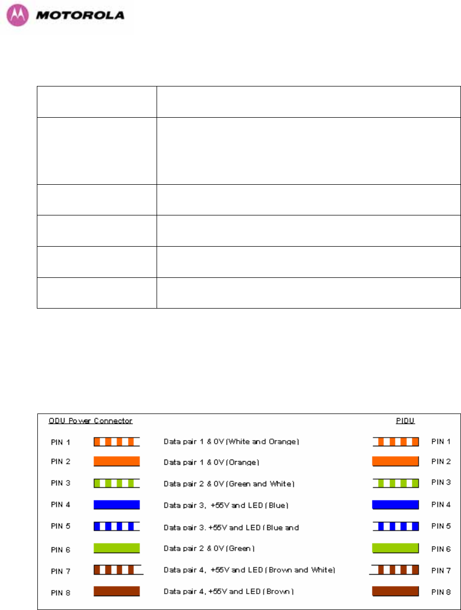
275
23.6 Environmental Specifications
Category Specification
Temperature
ODU: -40°F (-40°C) to 140°F (+60°C)
PIDU Plus: 32°F (0°C) to 104PPP
o
PPPF(+40°C)
PIDU Plus: -40°F (-40°C) to 140°F (+60°C)
Wind Loading 150mph Max (242kph). See Section 12 for a full description.
Humidity 100% Condensing
Waterproof IP65 (ODU), IP53 (PIDU Plus)
UV Exposure 10 year operational life (UL746C test evidence)
23.7 System Connections
23.7.1 PIDU Plus to ODU and ODU to Network Equipment Connections
Figure 164 - Cable Connection Diagram (T568B Color Coding)

276
Telecoms Connector Pinout Signal Name
Pin 1 E1T1A_TX-
Pin 2 E1T1A_TX+
Pin 3 E1T1A_RX-
Pin 4 E1T1B_TX-
Pin 5 E1T1B_TX+
Pin 6 E1T1A_RX+
Pin 7 E1T1B_RX-
Pin 8 E1T1B_RX+
Table 38 - Telecoms Connection Pin Out

277
Unit A1, Linhay Business Park
Eastern Road, Ashburton
Devon, TQ 13 7UP, UK
Telephone Support: +1 877 515-0400 (Worldwide)
+44 808 234 4640 (UK)
www.motorola.com/ptp
MOTOROLA, the stylized M Logo and all other trademarks indicated as such
herein are trademarks of Motorola, Inc. ® Reg. US Pat & Tm. Office. All other
product or service names are the property of their respective owners. © 2007
Motorola, Inc. All rights reserved.