Cambium Networks 54100 Fixed Point to Point Wireless Bridge User Manual PTP 400 Series User Guide
Cambium Networks Limited Fixed Point to Point Wireless Bridge PTP 400 Series User Guide
Contents
- 1. User Manual Revised
- 2. User Manual Part 1
- 3. User Manual Part 2
- 4. Manual 1
- 5. Manual 2
User Manual Part 1

PTP 600 Series
User Guide
MOTOROLA POINT-TO-POINT WIRELESS SOLUTIONS

1
MOTOROLA, Inc.
Point-to-Point Wireless Bridges – PTP 600 Series
Software Release PTP 600-05-02
System User Manual
October 10th, 2007
Ref: PHN-0896-01.11
Copyright Information
This document is the confidential property of Motorola, Inc. and without its prior written consent may
not be copied or released to third parties.
MOTOROLA, the stylized M Logo and all other trademarks indicated as such herein are trademarks
of Motorola, Inc. ® Reg. U.S. Pat & Tm. Office. PTP 600 is a trademark of Motorola, Inc. All other
product or service names are the property of their respective owners.
© 2007 Motorola, Inc. All rights reserved.
http://www.motorola.com/ptp
Compliance
General
Changes or modifications not expressly approved by Motorola could void the user’s authority to
operate the system.
NOTE: This system has achieved Type Approval in various countries around the world. This means
that the system has been tested against various local technical regulations and found to comply. The
frequency bands in which the system operates is may be ‘unlicensed’ and, in these bands, the system
can be used provided it does not cause interference. Further, it is not guaranteed protection against
interference from other products and installations.

2
The system has basically been shown to comply with the limits for emitted spurious radiation for a
Class B digital device1, pursuant to Part 15 of the FCC Rules in the USA as well as comparable
regulations in other countries. These limits have been designed to provide reasonable protection
against harmful interference in a residential installation. This equipment generates uses and can
radiate radio frequency energy and, if not installed and used in accordance with the instructions, may
cause harmful interference to radio communications. However, there is no guarantee that interference
will not occur in a particular installation.
If this equipment does cause harmful interference to radio or television reception, which can be
determined by turning the equipment off and on, the user is encouraged to try to correct the
interference by one or more of the following measures:
• Reorient or relocate the Outdoor Unit (ODU).
• Increase the separation between the equipment and ODU.
• Connect the equipment into a power outlet on a circuit different from that to which the
receiver is connected.
• Consult your installer or supplier for help.
Deployment and Operation
The Radio Regulations of various countries’ limits constrain the operation of radio products generally.
In particular the local regulator may limit the amount of conducted or radiated transmitter power and
may require registration of the radio link.
The power transmitted by the PTP 600 Series Bridge is controlled by the use of Region-specific
License Keys.
The following examples show how the regulatory limits apply in some specific countries at the current
time. Operators should note that regulations are subject to change.
Contact your supplier/installer to ensure that your product is set for the correct License Key for your
Country/Region and to ensure that you have fulfilled all the local regulatory requirements, especially if
you are intending to use a link with external antennas. Footnotes to the table below indicate countries
where registration of the link is currently mandatory.
1 Class B Digital Device, A digital device that is marketed for use in a residential environment notwithstanding use in
commercial, business and industrial environments.

3
Regulations applicable to 2.5GHz PTP 600 Series Bridge variant
Examples of Regulatory Limits at 2.5GHz
FCC
Under FCC Regulations, operation of this product
is only allowed with a License Key for Region 16
which ensures that the product will meet the
requirements of FCC part 27.
Note: Spectrum in this band (2496MHz to
2690MHz) is allocated on a Licensed basis in USA.
General Notice Applicable to Europe
N/A.

4
Regulations applicable to 5.4GHz PTP 600 Series Bridge variant
Examples of Regulatory Limits at 5.4GHz
Non-FCC and Non-ETSI2Equipment can be operated in any mode, best
results will be obtained using Region 8 settings
(Region 7 if DFS is required)
FCC Under FCC Regulations, operation of this product
is only allowed with a License Key for Region 12
(30dBm or 1W EIRP with Radar Detection)
ETSI Under ETSI Regulations, operation of this product
is only allowed with a License Key for Region 12
(30dBm or 1W EIRP with Radar Detection)
Australia, Canada
Under IC Regulations, operation of this product is
only allowed with a License Key for Region 13
(30dBm or 1W EIRP with Radar Detection and
barring of the band 5600-5650MHz)
Thailand Operation of this product is only allowed with a
License Key for Region 20 (30 dBm or 1W EIRP)
Korea Operation of this product is only allowed with a
License Key for Region 21 (30 dBm or 1W EIRP)
General Notice Applicable to Europe
This equipment complies with the essential requirements for the
EU R&E Directive 1999/5/EC.
And
2 Note: In regions other than EU/USA, specific local regulations may apply. It is the responsibility of the installer/user to check
that the equipment as deployed meets local regulatory requirements.

5
Regulations applicable to 5.8GHz PTP 600 Series Bridge variant
Examples of Regulatory Limits
USA/ Canada/ Taiwan/ Brazil Equipment can be operated in any mode, best
results will be obtained using Region 1 settings
China Operation of this product is only allowed with a
License Key for Region 2 (33 dBm or 2W EIRP)
Australia
A
ustralian laws prohibit use/operation of this
product except where it is used with a License Key
for Region 3 (4W EIRP)
Hong Kong Under Hong Kong Regulations, operation of this
product is only allowed with a License Key for
Region 3 (4W EIRP)
UK3Under UK Regulations, operation of this product is
allowed with a License Key for Region 4 (3W EIRP
with Radar Detection)
Singapore Under Singapore Regulations, operation of this
product is only allowed with a License Key for
Region 5 (100mW EIRP)
Eire4Under Eire Regulations, operation of this product is
only allowed with a License Key for Region 6 (2W
EIRP)
Korea Under Korean Regulations, operation of this
product is only allowed with a License Key for
Region 11 (1W EIRP)
India Operation of this product is only allowed with a
License Key for Region 19 (30 dBm or 1W EIRP)
Thailand Operation of this product is only allowed with a
License Key for Region 20 (30 dBm or 1W EIRP)
3UK Registration of Links – OfCom
The application form may be found at
http://www.ofcom.org.uk/radiocomms/
4Eire Registration of Links – Commission for Communication Regulation (ComReg)
The application form may be found at
http://www.comreg.ie/5_8GHzRegPart1.asp?S=4&NavID=198&M

6
General Notice Applicable to Europe
This equipment complies with the essential requirements for the
EU R&E Directive 1999/5/EC.
The use of 5.8GHz for Point to Point radio links is not harmonized
across the EU and currently the product may only be deployed in
the UK and Eire (IRL); Norway will be available for deployment
from December 2005.
However, the regulatory situation in Europe is changing and the
radio spectrum may become available in other countries in the near
future. Please contact Motorola for the latest situation.
!GB
IRL
0889
Disclaimer
The parameters quoted in this document must be specifically confirmed in writing
before they become applicable to any particular order or contract. The company
reserves the right to make alterations or amendments to the detail specification at its
discretion. The publication of information in this document does not imply freedom
from patent or other rights of Motorola, Inc. or others.

7
1 About This User Guide .......................................................................................................23
1.1 Interpreting Typeface and Other Conventions...................................................................... 23
1.2 Getting Additional Help ......................................................................................................... 25
1.3 Sending Feedback ................................................................................................................ 25
2 Avoiding Hazards................................................................................................................ 26
2.1 Preventing Overexposure to RF Energy............................................................................... 26
2.1.1 Calculations for Separation Distances and Power Compliance Margins.............................. 26
2.1.1.1 Calculated Distances and Power Compliance Margins ........................................................ 27
3 Getting Started ....................................................................................................................28
3.1 For Your Safety ..................................................................................................................... 28
3.2 Welcome ...............................................................................................................................29
3.2.1 About This Guide................................................................................................................... 29
3.2.2 Who Should Use This Guide................................................................................................. 29
3.2.3 Contact Information............................................................................................................... 30
3.2.4 Repair and Service................................................................................................................ 30
3.3 Product Description............................................................................................................... 31
3.3.1 The Outdoor Unit (ODU) ....................................................................................................... 33
3.3.2 PIDU Plus – PTP 600 Series Bridge..................................................................................... 34
3.3.3 Redundancy and Alternate Powering Configurations ........................................................... 36
3.3.3.1 External DC Supply Only ......................................................................................................36
3.3.3.2 External DC Supply and AC Supply......................................................................................37
3.3.3.3 External DC Supply and Redundant AC Supply...................................................................37
3.3.4 Remote LEDs and Recovery Switch..................................................................................... 38
3.3.5 Cables and connectors ......................................................................................................... 38
3.3.6 Surge Arrestor....................................................................................................................... 39
3.3.7 Mounting Brackets................................................................................................................. 39
3.3.8 Configuration and Management............................................................................................ 40
3.4 Warranty................................................................................................................................40
4 Product Architecture ..........................................................................................................41
5 General Considerations ..................................................................................................... 43
5.1 Spectrum Planning................................................................................................................ 43
5.2 Region Codes........................................................................................................................ 45
5.3 Operational Restrictions........................................................................................................ 47
5.3.1 Radar Avoidance................................................................................................................... 47
5.3.2 RTTT Avoidance and Other Channel Use Restrictions ........................................................ 48

8
5.3.3 Radar Avoidance, i-DFS and Variable (Narrow) Bandwidth Operation ................................ 49
5.4 Variable Channel Bandwidth Operation................................................................................ 49
5.5 2.5GHz Specific Frequency Planning Considerations .......................................................... 49
5.5.1 Power Reduction in the Upper Band..................................................................................... 51
5.6 5.4GHz Specific Frequency Planning Considerations .......................................................... 52
5.6.1 Raster Considerations........................................................................................................... 54
5.6.2 Transmit Power Reduction at the Band Edges..................................................................... 54
5.7 5.8GHz Specific Frequency Planning Considerations .......................................................... 54
5.7.1 Raster Considerations........................................................................................................... 56
5.7.2 Transmit Power Reduction at the Band Edges..................................................................... 56
5.8 Time Division Duplex (TDD) Synchronization....................................................................... 58
5.8.1 Introduction............................................................................................................................ 58
5.8.2 TDD Synchronization ............................................................................................................ 59
5.8.3 Deployment Consideration.................................................................................................... 59
5.8.4 PTP Approach for Using TDD Synchronization .................................................................... 59
5.9 Distance ................................................................................................................................59
5.10 Networking Information ......................................................................................................... 60
5.11 Lightning Protection............................................................................................................... 60
5.12 Electrical Requirements ........................................................................................................ 60
6 Site Planning........................................................................................................................ 61
6.1 Site Selection Criteria............................................................................................................ 61
6.1.1 ODU Site Selection ............................................................................................................... 61
6.1.2 PTP 600 Series Bridge PIDU Plus Site Selection................................................................. 61
6.1.3 Path Loss Considerations ..................................................................................................... 62
6.1.4 Definitions.............................................................................................................................. 62
6.1.5 2.5 GHz Product Variant - Link Loss, Output Power and System Threshold versus
Modulation Mode .................................................................................................................................. 63
6.1.6 5.4 GHz Product Variant - Link Loss, Output Power and System Thresholds versus
Modulation Mode .................................................................................................................................. 65
6.1.7 5.8 GHz Product Variant - Link Loss, Output Power and System Thresholds versus
Modulation Mode .................................................................................................................................. 67
7 Installation ...........................................................................................................................69
7.1 Preparation............................................................................................................................ 69
7.2 Installation Procedure ........................................................................................................... 69
7.3 Tools Required...................................................................................................................... 69
7.4 Installation Support................................................................................................................ 70
7.5 Legal Disclaimer.................................................................................................................... 70

9
7.6 Mounting the ODUs............................................................................................................... 70
7.7 Connecting Up....................................................................................................................... 72
7.7.1 Preparing the PIDU Plus To ODU Cable .............................................................................. 72
7.7.2 Making the Connections at the ODU..................................................................................... 74
7.7.3 Making the PTP 600 Series Bridge PIDU Plus Connection At The ODU ............................. 75
7.7.4 Routing the Cable.................................................................................................................. 76
7.7.5 Fitting A Surge Arrestor......................................................................................................... 76
7.7.6 Grounding the Installation..................................................................................................... 77
7.7.7 Making the ODU Connection at the PTP 600 Series Bridge PIDU Plus............................... 77
7.7.8 Making the Network Connection at The PIDU Plus – PTP 600 Series Bridge ..................... 78
7.7.9 Mounting the PTP 600 Series Bridge PIDU Plus.................................................................. 79
7.7.10 Powering Up.......................................................................................................................... 81
7.7.11 Aligning the PTP 600 Series Bridge ODUs........................................................................... 82
8 Web Page Reference...........................................................................................................84
8.1 Home Page – PTP 600 Series Bridge................................................................................... 86
8.1.1 Home Page Alarm Display.................................................................................................... 87
8.2 Systems Status Page............................................................................................................ 91
8.3 System Administration Pages ............................................................................................... 96
8.3.1 System Configuration............................................................................................................ 97
8.3.1.1 General Configuration Page.................................................................................................. 98
8.3.1.2 LAN Configuration Page .....................................................................................................100
8.3.1.3 LAN Configuration Page – Use VLAN For Management Interfaces...................................103
8.3.1.4 LAN Configuration Page – Manual Ethernet Configuration ................................................104
8.3.1.5 Save and Restore Configuration File ..................................................................................105
8.3.1.6 Telecoms Configuration Page.............................................................................................109
8.3.2 Statistics Page..................................................................................................................... 111
8.3.3 Detailed Counters Page ...................................................................................................... 114
8.3.4 Install Pages........................................................................................................................ 116
8.3.4.1 Manually Configuring The Wireless Units ...........................................................................118
8.3.4.2 Internet Protocol Configuration ...........................................................................................119
8.3.4.3 Telecoms Interface..............................................................................................................121
8.3.4.4 Wireless Configuration........................................................................................................ 122
8.3.4.5 Disarm.................................................................................................................................129
8.3.5 Graphical Install................................................................................................................... 131
8.3.6 Software Upgrade ............................................................................................................... 133
8.3.7 Spectrum Management....................................................................................................... 137

10
8.3.7.1 Wireless Channels .............................................................................................................. 137
8.3.7.2 Spectrum Management Measurements..............................................................................138
8.3.7.3 Measurement Analysis........................................................................................................ 138
8.3.7.4 The Spectrum Management Master / Slave Relationship...................................................139
8.3.7.5 Spectrum Management Configuration ................................................................................141
8.3.7.6 Barring Channels.................................................................................................................142
8.3.7.7 Local and Peer Channel Spectrum Graphics......................................................................142
8.3.7.8 Active Channel History........................................................................................................144
8.3.7.9 Viewing Historic Spectrum Management Metrics ...............................................................144
8.3.8 Spectrum Management (Fixed Frequency and WIMAX) .................................................... 146
8.3.9 Spectrum Management Control - With Operational Restrictions........................................ 147
8.3.10 Spectrum Management – Example of 2.5 GHz Product variant.........................................150
8.3.11 Remote Management Page ................................................................................................ 151
8.3.11.1 SNMP (Simple Network Management Protocol).................................................................152
8.3.11.2 Supported Management Information Bases (MIBS) ........................................................... 152
8.3.11.3 Diagnostics Alarms..............................................................................................................153
8.3.11.4 SNMP Configuration............................................................................................................154
8.3.11.5 SMTP (Simple Mail Transport Protocol)..............................................................................154
8.3.11.6 SNTP (Simple Network Time Protocol)...............................................................................155
8.3.11.7 Setting the clock..................................................................................................................155
8.3.12 Diagnostics.......................................................................................................................... 156
8.3.12.1 Diagnostic Plotter ................................................................................................................157
8.3.12.2 Diagnostics Download.........................................................................................................158
8.3.13 Change System Administration Password.......................................................................... 159
8.3.14 License Key......................................................................................................................... 159
8.3.15 Properties............................................................................................................................161
8.3.16 Reboot.................................................................................................................................162
9 Recovery Mode.................................................................................................................. 163
9.1 Upgrade Software Image ....................................................................................................165
9.2 Reset IP & Ethernet Configuration......................................................................................167
9.3 Erase Configuration.............................................................................................................168
9.4 Reboot.................................................................................................................................171
10 Fault Finding......................................................................................................................172
10.1 Hardware............................................................................................................................. 172
10.1.1 Power ..................................................................................................................................172
10.1.2 Ethernet............................................................................................................................... 173

11
10.1.3 Checking your wiring........................................................................................................... 174
10.2 Radio...................................................................................................................................175
10.2.1 No Activity ...........................................................................................................................175
10.2.2 Some Activity....................................................................................................................... 176
11 Lightning Protection......................................................................................................... 177
11.1 Overview .............................................................................................................................177
11.1.1 Lightning Protection Zones .................................................................................................177
11.2 Detailed Installation............................................................................................................. 178
11.3 Testing Your Installation...................................................................................................... 185
11.3.1 Pre-Power Testing...............................................................................................................185
11.3.2 Post-Power Testing............................................................................................................. 185
12 Wind Loading.....................................................................................................................187
12.1 General................................................................................................................................187
12.2 Calculation of Lateral Force ................................................................................................187
12.3 Capabilities of the PTP 600 Series Bridges ........................................................................188
12.4 Wind Speed Statistics ......................................................................................................... 188
13 PTP 600 Series Bridge – Connectorized Model .............................................................190
13.1 Scope ..................................................................................................................................190
13.2 Product Description............................................................................................................. 190
13.2.1 Hardware............................................................................................................................. 190
13.2.2 Antenna Choices – 5.8 GHz................................................................................................191
13.2.3 Antenna Choices – 5.4 GHz................................................................................................191
13.3 Software/Features............................................................................................................... 192
13.3.1 Status Page......................................................................................................................... 192
13.3.2 Configuration Pages............................................................................................................ 193
13.3.3 Installation Pages................................................................................................................ 194
13.4 Deployment Considerations................................................................................................197
13.5 Link Budget .........................................................................................................................197
13.6 Regulatory Issues................................................................................................................ 197
13.6.1 Antenna Choice (FCC Regions Only) ................................................................................. 197
13.6.2 Cable Losses (FCC Regions Only).....................................................................................198
13.7 Antennas for USA / Canada – 5.8 GHz...............................................................................198
13.8 Antennas for USA - 5.4 GHz...............................................................................................201
13.9 Installation ...........................................................................................................................203
13.9.1 Antenna Choice................................................................................................................... 203
13.9.2 Cables and Connectors....................................................................................................... 203

12
13.9.3 Tools....................................................................................................................................203
13.9.4 Miscellaneous supplies ....................................................................................................... 204
13.9.5 Mounting the Connectorized 600 Series Bridge .................................................................204
13.9.6 Mounting the antennas........................................................................................................ 204
13.9.7 Alignment Process .............................................................................................................. 205
13.9.8 Aligning Dual Polar Antennas .............................................................................................205
13.9.9 Aligning Separate Antennas................................................................................................ 205
13.9.10 Completing the Installation.................................................................................................. 206
13.9.11 Antenna Cable Fixing.......................................................................................................... 206
13.9.12 Antenna Connection Weatherproofing................................................................................ 206
13.10 Additional Lightning Protection............................................................................................ 208
13.10.1 ODU Mounted Outdoors ..................................................................................................... 208
13.10.2 ODU Mounted Indoors ........................................................................................................209
14 TDD Synchronization Configuration and Installation Guide ........................................ 210
14.1 Introduction.......................................................................................................................... 210
14.2 TDD Synchronization Installation and Wiring Guidelines....................................................211
14.2.1 Installing the Recommended GPS Synchronization Kit......................................................211
14.3 Configuring the TDD Synchronization Feature ................................................................... 214
14.3.1 TDD Synchronization Enable..............................................................................................214
14.3.2 TDD Synchronization Configuration Menu.......................................................................... 215
14.3.2.1 TDD Synchronization Configuration - Standard Mode.......................................................215
14.3.2.2 TDD Synchronization Configuration – Expert Mode ........................................................... 218
14.3.2.3 Confirm Settings and Reboot ODU.....................................................................................219
14.3.2.4 Disarm ODU Following TDD Sync Configuration................................................................ 221
15 E1/T1 Installation Guide ...................................................................................................222
15.1 Preparing the PTP 600 Series Bridge E1/T1 Cable............................................................ 222
15.2 Making the Connection at the ODU .................................................................................... 223
15.3 Routing the Cable................................................................................................................226
15.4 Fitting a Surge Arrestor....................................................................................................... 226
15.5 Customer Cable Termination ..............................................................................................226
16 Lightning Protection......................................................................................................... 229
16.1 Overview .............................................................................................................................229
16.2 Recommended Additional Components for E1/T1 Installation. ..........................................229
16.3 Surge Arrestor Wiring.......................................................................................................... 232
16.4 Testing Your Installation...................................................................................................... 234
16.4.1 Pre-Power Testing...............................................................................................................234

13
17 Data Rate Calculations .....................................................................................................236
18 AES Encryption Upgrade .................................................................................................243
18.1 Configuring Link Encryption ................................................................................................ 243
18.2 Configuring Link Encryption ................................................................................................ 243
18.2.1 License Keys.......................................................................................................................244
18.2.2 Encryption Mode and Key................................................................................................... 245
18.3 Wireless Link Encryption FAQ ............................................................................................247
18.3.1 Encryption data entry fields are not available .....................................................................247
18.3.2 Link fails to bridge packets after enabling link encryption................................................... 247
18.3.3 Loss of AES following downgrade....................................................................................... 247
19 Legal and Regulatory Notices..........................................................................................248
19.1 Important Note on Modifications .........................................................................................248
19.2 National and Regional Regulatory Notices – 5.8 GHz variant............................................ 248
19.2.1 U.S. Federal Communication Commission (FCC) and Industry Canada (IC) Notification.. 248
19.2.2 European Union Notification ...............................................................................................249
19.2.3 UK Notification..................................................................................................................... 250
19.3 National and Regional Regulatory Notices – 5.4 GHz Variant ...........................................251
19.3.1 U.S. Federal Communication Commission (FCC) and Industry Canada (IC) Notification.. 251
19.3.2 European Union Notification ...............................................................................................252
19.4 National and Regional Regulatory Notices – 2.5 GHz Variant ...........................................254
19.4.1 U.S. Federal Communication Commission (FCC) Notification ........................................... 254
19.5 Exposure .............................................................................................................................255
19.6 Legal Notices....................................................................................................................... 255
19.6.1 Software License Terms and Conditions ............................................................................255
19.6.2 Hardware Warranty in U.S. ................................................................................................. 259
19.6.3 Limit of Liability.................................................................................................................... 259
20 Glossary.............................................................................................................................260
21 FAQs...................................................................................................................................261
22 Index...................................................................................................................................263
23 Specifications....................................................................................................................264
23.1 System Specifications......................................................................................................... 264
23.1.1 Wireless 2.5 GHz Variant.................................................................................................... 264
23.1.2 Wireless 5.4GHz Variant..................................................................................................... 266
23.1.3 Wireless 5.8GHz Variant..................................................................................................... 268
23.1.4 Management .......................................................................................................................270
23.1.5 Physical...............................................................................................................................271

14
23.1.6 Powering .............................................................................................................................271
23.1.7 Telecoms Interface.............................................................................................................. 271
23.2 Safety Compliance .............................................................................................................. 272
23.3 EMC Emissions Compliance............................................................................................... 272
23.3.1 2.5GHz Variant.................................................................................................................... 272
23.3.2 5.4GHz Variant.................................................................................................................... 272
23.3.3 5.8GHz Variant.................................................................................................................... 272
23.4 EMC Immunity Compliance................................................................................................. 273
23.5 Radio Certifications............................................................................................................. 274
23.5.1 2.5 GHz Variant................................................................................................................... 274
23.5.2 5.4GHz Variant.................................................................................................................... 274
23.5.3 5.8GHz Variant.................................................................................................................... 274
23.6 Environmental Specifications.............................................................................................. 275
23.7 System Connections ...........................................................................................................275
23.7.1 PIDU Plus to ODU and ODU to Network Equipment Connections..................................... 275

15
List of Figures
Figure 1 - Typical PTP 600 Series Bridge Deployment...................................................................31
Figure 2 - Mod Record Label................................................................................................................32
Figure 3 – PTP 600 Series Bridge Outdoor Unit (ODU).......................................................................33
Figure 4 - Power Indoor Unit (PIDU Plus) – PTP 600 Series............................................................... 34
Figure 5 – PIDU Plus Recovery Switch Location.................................................................................34
Figure 6 – PTP 600 Series Bridge PIDU Plus Power Input..................................................................35
Figure 7 – PTP 600 Series Bridge PIDU Plus to ODU Cable Length Graph .......................................36
Figure 8 - External DC Supply Only .....................................................................................................36
Figure 9 - External DC Supply and AC Supply.....................................................................................37
Figure 10 - External DC Supply and Redundant AC Supply................................................................ 37
Figure 11 - Remote LED and Recovery Switch Wiring ........................................................................38
Figure 12 – PTP 600 Series Bridge Layer Diagram............................................................................. 42
Figure 13 - 5.8 GHz UK RTTT Channel Avoidance – 30 MHz Channel Bandwidth Only....................48
Figure 14 - 2.5 GHz BRS Band Channel Assignments........................................................................51
Figure 15 - 5.4 GHz Available Spectrum Settings - 30 MHz Channel Bandwidth................................ 52
Figure 16 - 5.4 GHz Available Spectrum Settings - 15 MHz Channel Bandwidth................................ 52
Figure 17 - 5.4 GHz Available Spectrum Settings - 10 MHz Channel Bandwidth................................ 53
Figure 18 - 5.4 GHz Available Spectrum Settings - 5 MHz Channel Bandwidth..................................53
Figure 19 - 5.8 GHz Available Spectrum Settings – 30 MHz Channel Bandwidth...............................54
Figure 20 - 5.8 GHz Available Spectrum Settings - 15 MHz Channel Bandwidth................................ 55
Figure 21 - 5.8 GHz Available Spectrum Settings - 10 MHz Channel Bandwidth................................ 55
Figure 22 - 5.8 GHz Available Spectrum Settings - 5 MHz Channel Bandwidth..................................55
Figure 23 - 5.8 GHz Band Edge TX Power Reduction (Region Code 1 Only) – 30 MHz Channel
Bandwidth Operation..................................................................................................................... 57
Figure 24 - Co-location of Links Interference Problem - A Simple Example........................................58
Figure 25 - Mounting to pole diameters 25mm (1”) to 50mm (2”) ........................................................71
Figure 26 - Integral Safety Loop...........................................................................................................71
Figure 27 - Completed ODU connector................................................................................................73
Figure 28 - RJ45 Pin Connection (T568B Color Coding) ..................................................................... 73
Figure 29 – PTP 600 Series Bridge PIDU Plus Connection.................................................................74
Figure 30 - Disconnecting the ODU...................................................................................................... 76
Figure 31 - Making the Network Connection at the PIDU Plus ............................................................78
Figure 32 – PTP 600 Series PIDU Plus Drip Loop Configuration ........................................................80
Figure 33 - Menu Navigation Bar..........................................................................................................85
Figure 34 - System Summary Page .....................................................................................................86

16
Figure 35 - Alarm Warning Triangle ..................................................................................................... 87
Figure 36 - Status Page........................................................................................................................ 91
Figure 37 - System Administration Login Page.................................................................................... 96
Figure 38 - System Configuration Page ...............................................................................................98
Figure 39 - LAN Configuration Page ..................................................................................................100
Figure 40 - Configuration Reboot Page..............................................................................................102
Figure 41 - Configuration Reboot Page - Ethernet Auto Negotiation Disabled.................................. 102
Figure 42 - VLAN Configuration Fields...............................................................................................103
Figure 43 - LAN Configuration Page - Manual Ethernet Configuration..............................................104
Figure 44 - Save and Restore Configuration Page ............................................................................105
Figure 45 - Save Configuration File Screen .......................................................................................106
Figure 46 – PTP 600 Example Configuration File..............................................................................106
Figure 47 - Restore Configuration File Pop Up Screen......................................................................107
Figure 48 - Reset Configuration and Reboot Confirmation Pop-up ...................................................108
Figure 49 - Telecoms Data Entry........................................................................................................109
Figure 50 - System Statistics.............................................................................................................. 111
Figure 51 - Detailed Counters Page................................................................................................... 114
Figure 52 - License Key Data Entry....................................................................................................118
Figure 53 - Installation Wizard Internet Protocol Configuration..........................................................119
Figure 54 - VLAN Warning .................................................................................................................120
Figure 55 - Telecoms Configuration Interface....................................................................................121
Figure 56 – 5.8 GHz and 5.4 GHz Variants - Installation Wizard Wireless Configuration .................122
Figure 57 - 2.5 GHz Variant - Installation Wizard Wireless Configuration .........................................123
Figure 58 – 5.8 GHz and 5.4 GHz Variants - Fixed Frequency Operation......................................... 126
Figure 59 - 2.5 GHz Variant - Fixed Frequency Operation.................................................................126
Figure 60 – 5.8 GHz and 5.4 GHz Variants - Installation Wizard Confirm Configuration...................127
Figure 61 - 2.5 GHz Variant - Installation Wizard Confirm Configuration........................................... 128
Figure 62 - Reboot Confirmation Pop Up ...........................................................................................128
Figure 63 – 5.8 GHz and 5.4 GHz Variant - Disarm Installation ........................................................129
Figure 64 - 2.5 GHz Variant - Disarm Installation............................................................................... 130
Figure 65 - Optional Post Disarm Configuration 1..............................................................................131
Figure 66 - Optional Post Disarm Configuration 2..............................................................................131
Figure 67 – Graphical Installation Screen ..........................................................................................132
Figure 68 - Software Upgrade ............................................................................................................ 133
Figure 69 - Software Upgrade Image Check...................................................................................... 134
Figure 70 - Software Download Progress Indicator............................................................................135
Figure 71 - Software Upgrade Complete............................................................................................135

17
Figure 72 - Reboot Confirmation Pop Up ...........................................................................................136
Figure 73 - Spectrum Management as seen from the Master............................................................140
Figure 74 - Spectrum Management as seen from the Slave.............................................................. 140
Figure 75 - Example Spectrum Management Graphic.......................................................................142
Figure 76 - Active Channel History Screen ........................................................................................ 144
Figure 77 - Spectrum Management Time Series Plot ........................................................................144
Figure 78 - Spectrum Management Fixed Frequency Screen ...........................................................146
Figure 79 - Spectrum Management Help Page (Fixed Frequency) ...................................................147
Figure 80 - Spectrum Management Master Screen With Operational Restrictions ........................... 148
Figure 81 - Spectrum Management Slave Screen With Operational Restrictions .............................149
Figure 82 - 2.5 GHz Example of Spectrum Management Page.........................................................150
Figure 83 - Remote Management.......................................................................................................151
Figure 84 - Remote Management - Diagnostic Alarms ......................................................................153
Figure 85 - Diagnostic Plotter............................................................................................................. 157
Figure 86 - CSV Download................................................................................................................. 158
Figure 87 - Password Change............................................................................................................159
Figure 88 - Software License Key Data Entry ....................................................................................159
Figure 89: License Key reboot Screen ...............................................................................................160
Figure 90 - Reboot Confirmation Pop Up ...........................................................................................160
Figure 91 – Properties........................................................................................................................ 161
Figure 92 - System Reboot.................................................................................................................162
Figure 93 - Reboot Confirmation Pop Up ...........................................................................................162
Figure 94 - Recovery Mode Warning Page ........................................................................................163
Figure 95 - Recovery Options Page ...................................................................................................164
Figure 96 - Software Download Progress Indicator Page ..................................................................165
Figure 97 - Software Download Complete Page................................................................................165
Figure 98 - Reboot Confirmation Pop Up ...........................................................................................166
Figure 99 - Confirm Reset to Factory Default Pop Up........................................................................167
Figure 100 - IP and Ethernet Erased Successfully page....................................................................167
Figure 101 - Reboot Confirmation Pop Up.........................................................................................168
Figure 102 - Confirm Erase Configuration Pop Up.............................................................................168
Figure 103 - Erase Configuration Successful Page ........................................................................... 169
Figure 104 – Erase Configuration - Reboot Confirmation Pop Up.....................................................170
Figure 105 – Recovery - Reboot Confirmation Pop Up......................................................................171
Figure 106 - Main System Connections .............................................................................................172
Figure 107 - ODU mounted in Zones A & B....................................................................................... 179
Figure 108 - Showing how the use of a Finial enables the ODU to be mounted inside Zone B ........179

18
Figure 109 - Diagrammatically showing typical wall and mast installations.......................................180
Figure 110 - Upper Grounding Configuration..................................................................................... 181
Figure 111 - Lower Grounding Configuration .....................................................................................182
Figure 112 - Surge Arrestor ALPU-ORT Connection Illustration........................................................184
Figure 113 - Simplified Circuit Diagram (Only One Transtector Shown For Clarity)..........................185
Figure 114 – Connectorized 600 Series Bridge Outdoor Unit............................................................190
Figure 115 - Connectorized 600 Series bridge Status Page..............................................................192
Figure 116 - Connectorized 600 Series bridge ‘System Configuration’ Page.................................... 193
Figure 117 - Connectorized PTP 600 Series Bridge ‘Installation Wizard’ Page ................................194
Figure 118 - Connectorized 600 Series bridge ‘Confirm Installation’ Page........................................195
Figure 119 - Connectorized 600 Series bridge ‘Disarm Installation’ Page......................................... 196
Figure 120 - Forming a Drip Loop ...................................................................................................... 206
Figure 121 - Weatherproofing the Antenna Connections...................................................................207
Figure 122- Additional Grounding When Using Connectorized Units ................................................208
Figure 123 - Lightning Arrestor Mounting...........................................................................................209
Figure 124 - Polyphaser Assembly.....................................................................................................209
Figure 125 - GPS Synchronization Unit..............................................................................................212
Figure 126 - GPS Synchronization Unit Connections ........................................................................212
Figure 127 - TDD Sync - PTP600 Deployment Diagram....................................................................213
Figure 128- GPS Synchronization Unit Complete Installation............................................................ 213
Figure 129 - Enabling TDD Synchronization Feature.........................................................................214
Figure 130 - Configuring TDD Synchronization – Screen 1............................................................... 215
Figure 131 - Configuring TDD Synchronization Feature - Screen 2 ..................................................217
Figure 132 - Configure TDD Synchronization Expert Mode...............................................................218
Figure 133 - Confirm TDD Synchronization Configuration Parameters .............................................219
Figure 134 - Status Page - TDD Enabled and Synchronized.............................................................220
Figure 135 - Status Page - TDD Enabled and Not Synchronized.....................................................220
Figure 136 - Disarm Following TDD Synchronization ........................................................................ 221
Figure 137 - Completed ODU Connector ...........................................................................................222
Figure 138 - RJ45 Pin Connection (T568B Color Coding) .................................................................223
Figure 139 - PIDU Plus and E1-T1 Connection .................................................................................223
Figure 140 - Disconnecting the ODU..................................................................................................225
Figure 141 - Example of a Balun........................................................................................................226
Figure 142 - Diagrammatically Showing the E1-T1 Connections....................................................... 227
Figure 143 - Two E1-T1-120 Ohms signal Balanced to PTP600 Interface........................................228
Figure 144 - Typical Mast Installation with the addition of the E1-T1 cable.......................................230
Figure 145 - Wall Installation with the addition of E1-T1 cable ..........................................................231

19
Figure 146 - Surge Arrestor ALPU-ORT Connection Illustration........................................................233
Figure 147 - Simplified Circuit Diagram (Only One Transtector Shown For Clarity)..........................234
Figure 148 - BPSK 0.63 Single Payload.............................................................................................236
Figure 149 - QPSK 0.63 Single Payload ............................................................................................237
Figure 150 - QPSK 0.87 Single Payload ............................................................................................237
Figure 151 - 16 QAM 0.63 Single Payload.........................................................................................238
Figure 152 - 16 QAM 0.87 Single Payload.........................................................................................238
Figure 153 - 64 QAM 0.75 Single Payload.........................................................................................239
Figure 154 - 64 QAM 0.92 Single Payload.........................................................................................239
Figure 155 - 256 QAM 0.81 Single Payload.......................................................................................240
Figure 156 - 16 QAM 0.63 Dual Payload ...........................................................................................240
Figure 157 - 16 QAM 0.87 Dual Payload ...........................................................................................241
Figure 158 - 64 QAM 0.75 Dual Payload ...........................................................................................241
Figure 159 - 64 QAM 0.92 Dual Payload ...........................................................................................242
Figure 160 - 256 QAM 0.81 Dual Payload .........................................................................................242
Figure 161 – AES Software License Key Data Entry ......................................................................... 244
Figure 162 – AES Configuration Data Entry Page .............................................................................245
Figure 163 - Configuration Reboot Screen......................................................................................... 246
Figure 164 - Cable Connection Diagram (T568B Color Coding)........................................................275

20
List of Tables
Table 1 - Font types............................................................................................................................ 23
Table 2 - Admonition types...................................................................................................................24
Table 3 - Power Compliance Margins ..................................................................................................27
Table 4 - Contact Information...............................................................................................................30
Table 5 - PTP 600 Series Bridge Frequency Variants ......................................................................... 43
Table 6 – PTP 600 Series Bridge Region Code Definitions................................................................. 46
Table 7 - 2.5 GHz Product Variant Channel Plan - FCC BRS-EBS Post-Transition Band ..................50
Table 8 - Power Reduction in the Upper Band.....................................................................................51
Table 9 - 5.8 GHz Band Edge Tx Power Reduction –.......................................................................... 56
Table 10 - 2.5GHz- IP Mode – Loss, Output Power and System Threshold Vs Modulation Mode .....63
Table 11 - 2.5GHz- TDM Mode – Loss, Output Power and System Threshold Vs Modulation Mode.64
Table 12 – 5.4GHz - IP Mode - Link Loss, Output Power, System Threshold Vs Modulation Mode... 65
Table 13 – 5.4GHz -TDM Mode - Link Loss, Output Power, System Threshold Vs Modulation Mode66
Table 14 - 5.8GHz - IP Mode - Link Loss, Output Power, System Threshold Vs Modulation Mode.... 67
Table 15 - 5.8GHz - TDM Mode - Link Loss, Output Power, System Threshold Vs Modulation Mode68
Table 16 - Audio indications from the ODU.......................................................................................... 82 U
Table 17 – 600 Series Bridge Factory Configuration Values ............................................................. 117
Table 18 - Spectrum Management change state key......................................................................... 143
Table 19 - Spectrum Management Time Series Key .........................................................................145
Table 20 - Spectrum Management Change State Key With Operational Restrictions.......................149
Table 21 - Resistance Table Referenced To The RJ45 at the PIDU+ ............................................... 175
Table 22 - Protection Requirements...................................................................................................180
Table 23 - Surge Arrestor ALPU-ORT Cable 1 Termination ..............................................................183
Table 24 - Surge Arrestor ALPU-ORT Cable 2 Termination ..............................................................183
Table 25 - Lateral Force – Imperial .................................................................................................... 187
Table 26 - Lateral Force – Metric .......................................................................................................188
Table 27 - Cable Losses per Length ..................................................................................................198
Table 28 - Allowed Antennas for Deployment in USA/Canada – 5.8 GHz......................................... 200
Table 29 - Allowed Antennas for Deployment in USA/Canada – 5.4 GHz......................................... 202
Table 30 - Common Burst Durations..................................................................................................216
Table 31 - Protection Requirements...................................................................................................229
Table 32 - Surge Arrestor ALPU-ORT Cable 1 Termination ..............................................................232
Table 33 - Surge Arrestor ALPU-ORT Cable 2 Termination ..............................................................232
Table 34 - Resistance Table Referenced To the E1/T1 Source ........................................................235
Table 35 - US FCC IDs and Industry Canada certification numbers.................................................. 249

21
Table 36 - US FCC IDs and Industry Canada certification numbers.................................................. 251
Table 37 - US FCC IDs and Industry Canada certification numbers.................................................. 254
Table 38 - Telecoms Connection Pin Out...........................................................................................276

22
List of Equations
Equation 1 - Path Loss ......................................................................................................................... 62
Equation 2 - Link Loss..........................................................................................................................94

23
1 About This User Guide
This guide covers the installation, commissioning, operation and fault finding of the Motorola
PTP 600 Series of Point-to-Point Wireless Ethernet Bridges.
1.1 Interpreting Typeface and Other Conventions
This document employs distinctive fonts to indicate the type of information, as described in
Table 1.
Font Type of Information
variable width bold Selectable option in a graphical user interface or
settable parameter in a web-based interface.
constant width regular Literal system response in a command-line interface.
constant width italic Variable system response in a command-line interface.
constant width bold Literal user input in a command-line interface.
constant width bold
italic Variable user input in a command-line interface.
Table 1 - Font types
This document employs specific imperative terminology as follows:
• Type means press the following characters.
• Enter means type the following characters and then press Enter.
• Highlight means click anywhere in a row of data to highlight the entire row.
• Select means use the mouse to click on or branch to the menu item that follows.
Use this table and the Glossary to aid in interpreting the technical acronyms used throughout
this User Guide.
24
This document also employs a set of consistently used admonitions. Each type of admonition
has a general purpose that underlies the specific information in the box. These purposes are
indicated in Table 2.
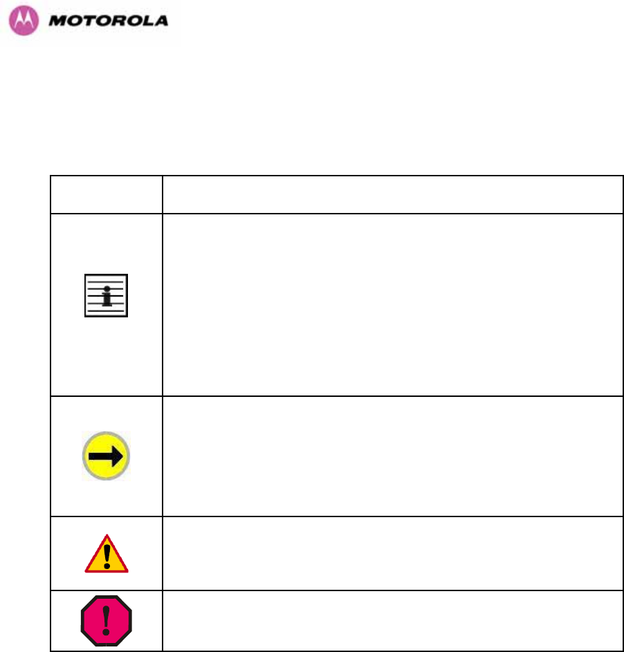
Admonition
Label General Message
Note Informative content that may:
• Defy common or cursory logic.
• Describe a peculiarity of the 600 Series solutions implementation.
• Add a conditional caveat.
• Provide a reference.
• Explain the reason for a preceding statement or provide background
for what immediately follows.
Recommendation Suggestion for an easier, quicker, or safer action or
practice.
Important Informative content that may:
• Identify an indication that you should watch for.
• Advise that your action can disturb something that you may not want
disturbed.
• Reiterate something that you presumably know but should always
keep in mind.
Caution! A notice that the risk of harm to equipment or service exists.
Warning! A notice that the risk of harm to person exists.
Table 2 - Admonition types

25
1.2 Getting Additional Help
To get information or assistance as soon as possible for problems that you encounter, use
the following sequence of action:
1. Search this document, the user manuals that support the modules, and the software
release notes of supported releases:
a. In the Table of Contents for the topic.
b. In the Adobe Reader® search capability for keywords that apply.5
2. Visit the Motorola website at www.motorola.com/ptp
3. Ask your Motorola products supplier to help.
4. Gather information from affected units such as:
a. the IP addresses and MAC addresses
b. the software releases
c. the configuration of software features
d. any available diagnostic downloads
5. Escalate the problem to Motorola Technical Support as follows. You may either:
a. Send e-mail to support.ptp@motorola.com
b. Call our 24x7 Technical Support Center on +1 (0) 877 515 0400 (Worldwide) or
+44 (0) 808 234 4640 (UK Customers).
For warranty assistance, contact your reseller or distributor for the process.
1.3 Sending Feedback
We welcome your feedback on the PTP 600 Series Bridge system documentation. This
includes feedback on the structure, content, accuracy, or completeness of our documents,
and any other comments you have.
5 Reader is a registered trademark of Adobe Systems, Incorporated.
26
2 Avoiding Hazards
2.1 Preventing Overexposure to RF Energy
Caution To protect from overexposure to RF energy, install the radios for the 600 family of
PTP wireless solutions so as to provide and maintain the minimum separation distances from
all persons as shown in Table 3.
When the system is operational, avoid standing directly in front of the antenna. Strong RF
fields are present when the transmitter is on. The Outdoor Unit (ODU) must not be deployed
in a location where it is possible for people to stand or walk inadvertently in front of the
antenna.
At these and greater separation distances, the power density from the RF field is below
generally accepted limits for the general population.
Note These are conservative distances that include compliance margins.
2.1.1 Calculations for Separation Distances and Power Compliance Margins
Limits and guidelines for RF exposure come from:
• US FCC limits for the general population. See the FCC web site at http://www.fcc.gov,
and the policies, guidelines, and requirements in Part 1 of Title 47 of the Code of Federal
Regulations, as well as the guidelines and suggestions for evaluating compliance in FCC
OET Bulletin 65.
• Health Canada limits for the general population. See the Health Canada web site at
http://www.hc-sc.gc.ca/rpb and Safety Code 6.
• ICNIRP (International Commission on Non-Ionizing Radiation Protection) guidelines for
the general public. See the ICNIRP web site at http://www.icnirp.de/ and Guidelines for
Limiting Exposure to Time-Varying Electric, Magnetic, and Electromagnetic Fields.
The applicable power density exposure limits from the documents referenced above are:
• 6 W/m2 for RF energy in the 900-MHz frequency band in the US and Canada.
• 10 W/m2 for RF energy in the 2.4-, 5.2-, 5.4-, and 5.8-GHz frequency bands.

27
Peak power density in the far field of a radio frequency point source is calculated as follows:
Where S = power density in W/m
2
P = Maximum Average transmit power capability of the radio, in W
G = total Tx gain as a factor, converted from dB
d = distance from point source, in m
2
4
.
d
GP
S
π
=
Rearranging terms to solve for distance yields
S
GP
d.4
.
π
=
2.1.1.1 Calculated Distances and Power Compliance Margins
Table 3 shows calculated minimum separation distances d, recommended distances and
resulting power compliance margins for each frequency band and antenna combination.
Variable Band Antenna Max
Average
Transmit
Power in
Burst
(Watt)
P
(Watt) G S
(W/m2)
D1 (m) Recom-
mended
Distance
(m)
Power
Compliance
Margin
2.5 GHz Integrated 0.25 0.125 63
(18dBi) 10 0.25 2 8.0
Integrated 0.005
(7dBm) 0.00250 200
(23dBi) 10 0.06
5.4 GHz External
3ft Dish 0.00035
(-4.6dBm) 0.00017 2884
(34.6dBi) 10 0.06
1 15.9
Integrated 0.32
(25dBm) 0.16 200
(23dBi) 10 0.5 2 4.0
External
2ft Flat
Plate 0.32
(25dBm) 0.16 631
(28dBi) 10 0.9 4 4.5
5.8 GHz
External
6ft Dish 0.32
(25dBm) 0.16 6310
(38dbi) 10 2.83 10 3.5
1. Calculated
Table 3 - Power Compliance Margins
Notes:
1. The regulations require that the power used for the calculations is the maximum power in
the transmit burst subject to allowance for source-based time-averaging.
2. At 5.4GHz the product is generally to a fixed EIRP which can be achieved with the
Integrated Antenna. If there are no EIRP limits, use the distance calculations for 5.8GHz.
3. At 5.8GHz, for antennas between 2ft and 6ft, alter the distance proportionally to the
antenna gain.
4. At 2.5GHz, with a 4/12ft dish, the safe distance is increased to 08/2.4m.

28
3 Getting Started
3.1 For Your Safety
WARNING: Use extreme care when installing antennas near power lines.
WARNING: Use extreme care when working at heights.
WARNING: The Outdoor Unit (ODU) for the PTP 600 Series Bridge must be properly
grounded to protect against lightning. It is the user’s responsibility to install the equipment in
accordance with Section 810 of the National Electric Code, ANSI/NFPA No.70-1984 or
Section 54 of the Canadian Electrical Code. These codes describe correct installation
procedures for grounding the outdoor unit, mast, lead-in wire and discharge unit, size of
grounding conductors and connection requirements for grounding electrodes. It is
recommended that installation of the outdoor unit be contracted to a professional installer.
WARNING: The ODU for the PTP 600 Series Bridge must be grounded to a Protective Earth
as described in Section 5.7.6 ”Grounding The Installation” of this Installation Manual and in
accordance with the Local Electrical Regulations.
WARNING: It is recommended that the supplied Power Indoor Plus (PIDU Plus) – PTP 600
Series is used to power the PTP 600 Series Bridge ODU. The use of other power sources
may invalidate safety approval and affect your warranty.
WARNING: When using alternate DC supplies (via the PIDU Plus DC in terminals as
described in Section 1.3.3 “Redundancy and Alternate Powering Configurations”), such as
battery-backed DC power source, the supply MUST comply with the following requirements:
• The voltage and polarity is correct and is applied to the correct terminals in the PIDU Plus
• The power source is rated as SELV
• The power source is rated to supply at least 1A continuously, and
• The power source cannot provide more than the Energy Hazard Limit as defined by
IEC/EN/UL6090, Clause 2.5, Limited Power (The Energy Hazard Limit is 240VA)
CAUTION: Users and installers should note that the main power supply is the primary
disconnect device.

29
CAUTION: Safety will be compromised if external quality cables are not used for connections
that will be exposed to the weather.
CAUTION: Safety will be compromised if a different power supply is used than the one
supplied by Motorola as part of the system.
3.2 Welcome
Congratulations on the purchase of the PTP 600 Series Bridge from Motorola. The PTP 600
Series Bridge is the latest innovation in high-speed wireless networking that lets you deploy
wireless networks in areas previously unattainable.
3.2.1 About This Guide
This guide covers the installation, commissioning, operation and fault finding of the PTP 600
Series Bridge.
3.2.2 Who Should Use This Guide
The guide is for use by the system installer and the end user IT professional.
The system installer will require expertise in the following areas:
• Outdoor radio equipment installation
• Network configuration
• Use of web browser for system configuration, monitoring and fault finding
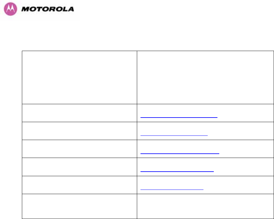
30
3.2.3 Contact Information
Postal Address:
Motorola, Inc.
Unit A1, Linhay Business Park,
Eastern Road,
Ashburton,
Devon. TQ13 7UP
United Kingdom
Web Site: http://www.motorola.com/ptp
Sales Enquiries: sales.ptp@motorola.com
Web Support: http://www.motorola.com/ptp/
Email Support: support.ptp@motorola.com
All Other Enquiries: info.ptp@motorola.com
Telephone Enquiries and Global
Support: +1 (0) 877 515 0400 (Toll Free in the USA) and
+44 (0) 808 234 4640 (Toll Free in the Uk).
Table 4 - Contact Information
3.2.4 Repair and Service
For unit repair or service, contact your service provider or an authorized Motorola Point-to-
Point Distributor for Return Material Authorization (RMA) and shipping instructions.
Alternatively, contact the PTP Global Technical Support Center to process an RMA (following
troubleshooting).
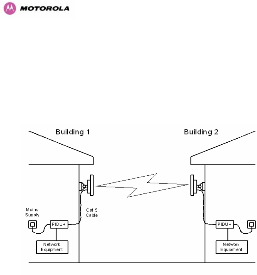
31
3.3 Product Description
This User Manual is specifically written for the 600 family of point-to-point broadband wireless
solutions. The PTP 600 Series Bridge has been developed to provide Point-to-Point data
connectivity via a 2.5 GHz, 5.4 GHz or 5.8 GHz wireless Ethernet bridge operating at
broadband data rates. The PTP 600 Series Bridge is aimed at a wide range of applications.
An example application is an enterprise that has a requirement to connect together the Local
Area Network (LAN) of two or more buildings as shown in Figure 1.
Figure 1 - Typical PTP 600 Series Bridge Deployment
The PTP 600 Series Bridge offers true non-line-of-sight (NLOS) operation by using a
combination of Orthogonal Frequency Division Multiplexing (OFDM) modulation and Multiple-
Input Multiple-Output (MIMO) techniques. These technologies enable the PTP 600 Series
Bridge to drive through foliage and around buildings to such an extent that almost universal
coverage can be expected at short range.
A PTP 600 Series Bridge system consists of a pair of identical devices that are deployed one
at each end of the link. At installation, the user sets up one unit as the Master and the other
as the Slave. Either unit can be configured as Master or Slave.

32
Each end of the link consists of:
• An integrated outdoor transceiver unit containing all the radio and networking electronics
hereafter referred to as the Outdoor Unit (ODU).
• An indoor connection box containing a mains power supply, status indicators and network
connection port. Hereafter referred to as the Power Indoor Unit Plus (PIDU Plus).
A pair of units is normally supplied pre-configured as a link.
The network connection to a PTP 600 Series Bridge is made via a 1000BaseT Ethernet
connection. Power is provided to the ODU over the 1000BaseT Ethernet connection using a
patented non-standard powering technique.
Previous releases of the PTP 600 Series Bridge platform used different powering and
connection arrangements. Users of equipment prior to “Mod Record 1” should refer to the
User Guide shipped with the original equipment. The “Mod Record” label can be found on the
back of the ODU as shown in Figure 2.
Figure 2 - Mod Record Label

33
Alternately, the network connection to a PTP 600 Series Bridge can be made using a
1000BaseSX Fiber Optic cable connected directly to the ODU. In this case power is still
provided over the 1000BaseT Ethernet connection. In the case of Fiber Optic cable failure the
PTP 600 Series Bridge will automatically fall back to the copper Ethernet connection
(provided the cable length <=100m [330 ft]). “PTP 600 Series Optical Interface Upgrade Kits”
can be obtained from your distributor, reseller or system integrator.
Power is fed into the PTP 600 Series Bridge PIDU Plus from the mains via a standard “figure
of eight” mains plug. Connection between the ODU and PIDU Plus is made using standard
CAT5e outdoor UV resistant cable. Connection between the PIDU Plus and the Network
Equipment is made using standard CAT5e cable.
3.3.1 The Outdoor Unit (ODU)
The ODU (Figure 3) is a self-contained unit. It houses both radio and networking electronics.
The ODU for the PTP 600 Series Bridge should only be deployed using the supplied PTP 600
Series Bridge PIDU Plus.
Figure 3 – PTP 600 Series Bridge Outdoor Unit (ODU)
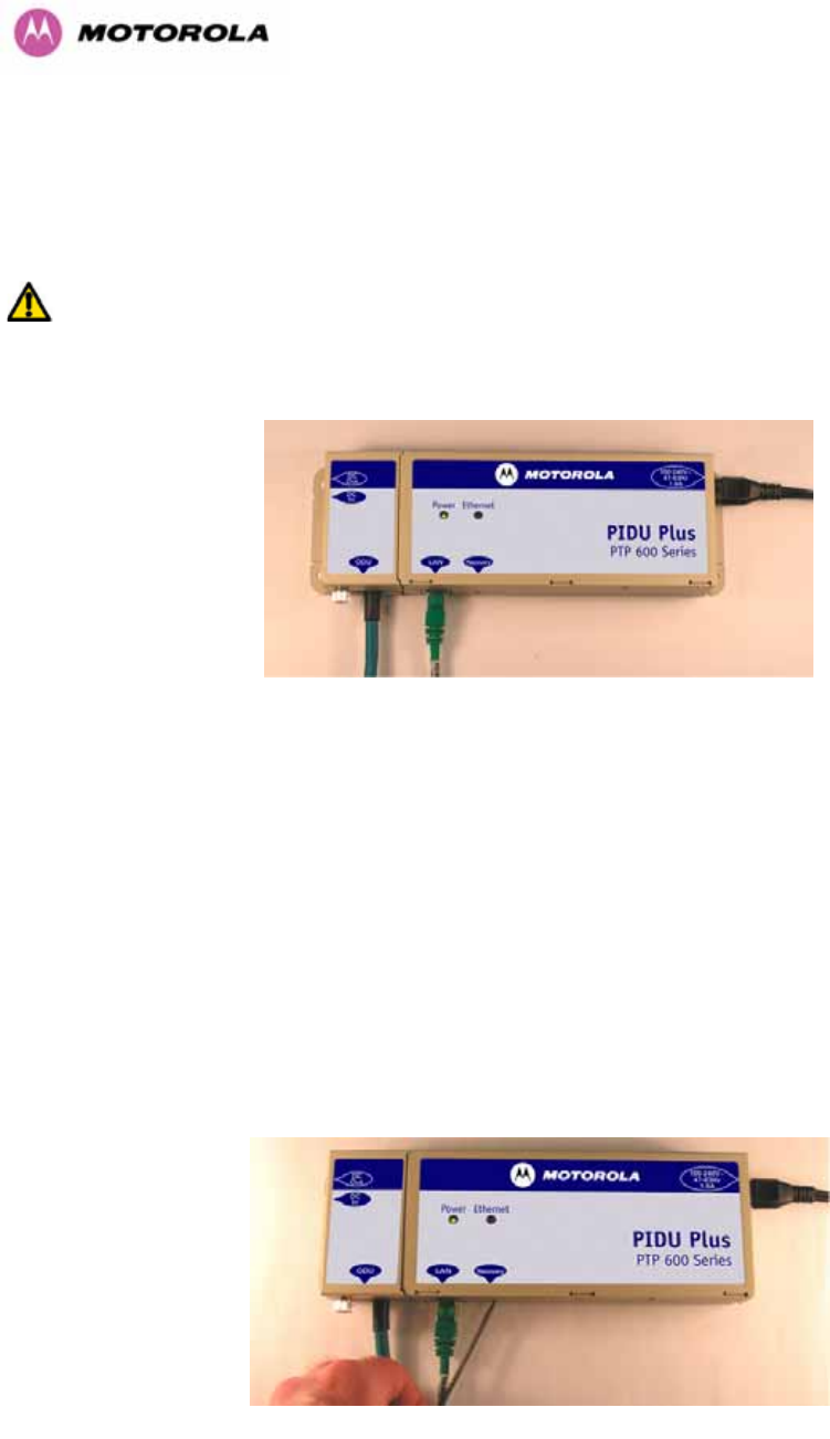
34
3.3.2 PIDU Plus – PTP 600 Series Bridge
The PTP 600 Series Bridge PIDU Plus is used to generate the ODU supply voltage from the
mains supply and inject this supply voltage into the 1000BaseT Ethernet connection to the
ODU. Connection uses a CAT5e cable using standard RJ45 wiring.
WARNING Care should be taken not to connect equipment other than an ODU for the PTP
600 Series Bridge to a PIDU Plus ODU port as equipment damage may occur. The PTP 600
Series Bridge PIDU Plus is not interchangeable with the PTP 600 Series Bridge PIDU Plus.
Figure 4 - Power Indoor Unit (PIDU Plus) – PTP 600 Series
The front panel contains indicators showing the status of the power and Ethernet
connections.
The power indicator is illuminated when the PIDU Plus is receiving mains power.
The Ethernet indicator normally illuminates when the Ethernet link is working, flashing when
there is Ethernet activity. The fact that it lights also indicates that the ODU is powered. At
power up the LED will flash 10 times to indicate that a correct start up sequence has
occurred. See Section 8 “Fault Finding” for further fault finding information.
At the bottom of the PIDU Plus is an entry point for the PIDU Plus to ODU cable, the
1000BaseT Ethernet network port and the Recovery switch.
Figure 5 – PIDU Plus Recovery Switch Location

35
The Recovery switch is used to recover the unit from configuration errors or software image
corruption. To put a PTP 600 Series Bridge into Recovery mode the Recovery switch should
be pressed then the power applied. The Recovery switch should be kept pressed for at least
20 seconds after the power has been applied. Full instruction on the recovery mode can be
found in Section 9 “Recovery Mode”.
A simple reboot can be performed by removing and re-applying the mains power to the PTP
600 Series Bridge PIDU Plus.
On the left hand side of the PIDU Plus, 48V DC input and output connections can be found.
These are used to power the PTP 600 Series Bridge from an external DC source or to
provide a level of power supply redundancy, as shown in Section 1.3.3 “Redundancy and
Alternate Powering Configurations”.
WARNING When using alternate DC supplies the supply MUST comply with the following
requirements:
• The voltage and polarity is correct and is applied to the correct terminals in the PIDU Plus
• The power source is rated as SELV
• The power source is rated to supply at least 1A continuously, and
• The power source cannot provide more than the Energy Hazard Limit as defined by
IEC/EN/UL6090, Clause 2.5, Limited Power (The Energy Hazard Limit is 240VA)
Also on the left hand side of the PTP 600 Series Bridge PIDU Plus, connectors and jumpers
can be found that allow the remote connection of power LED, Ethernet LED and Recovery
switch. The connection instructions can be found in Section 1.3.4 “Remote LEDs and
Recovery Switch”
The input supply range for the 600 Series PIDU Plus is 100V-240V AC, 47-63Hz. Mains
connection to the PIDU Plus is made using a standard “figure of eight” mains lead as shown
in Figure 6.
Figure 6 – PTP 600 Series Bridge PIDU Plus Power Input
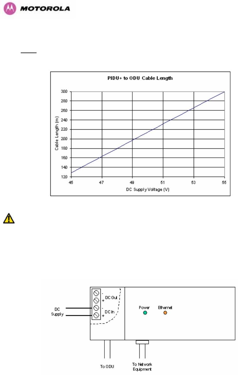
36
3.3.3 Redundancy and Alternate Powering Configurations
NOTE: The use of DC supplies of less than 55v will reduce the usable distance between the
PIDU Plus and ODU see Figure 7.
Figure 7 – PTP 600 Series Bridge PIDU Plus to ODU Cable Length Graph
WARNING: The maximum distance from the ODU to the connected network equipment is
100m (330 ft) when using 1000BaseT. Powering distances over 100m (330 ft) are only
applicable when using a 1000BaseSX (Fiber Optic) connection.
3.3.3.1 External DC Supply Only
For use where there is no mains supply.
Figure 8 - External DC Supply Only
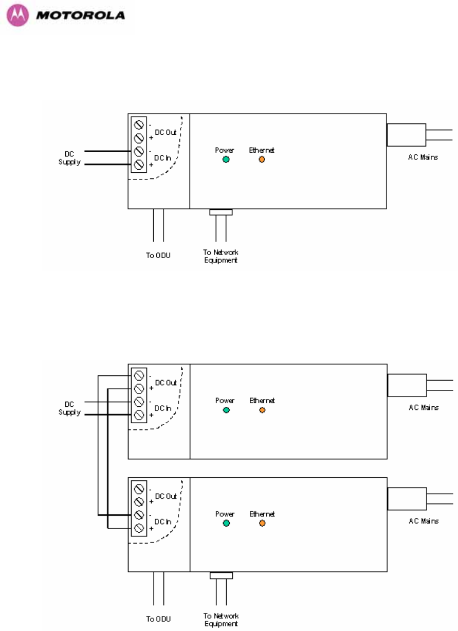
37
3.3.3.2 External DC Supply and AC Supply
To give redundancy through the use of mains and DC supply.
Figure 9 - External DC Supply and AC Supply
3.3.3.3 External DC Supply and Redundant AC Supply
To guard against mains failure, DC supply failure of PTP 600 Series Bridge PIDU Plus failure.
Figure 10 - External DC Supply and Redundant AC Supply
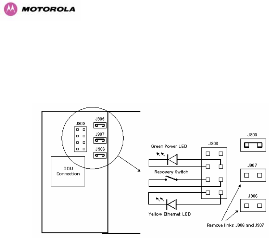
38
3.3.4 Remote LEDs and Recovery Switch
The PTP 600 Series Bridge PIDU Plus provides a facility to connect remote LEDs and
Recovery switch allowing the PIDU Plus to be mounted inside an enclosure. At the left hand
end of the PIDU Plus under the ODU connection cover can be found a PCB header and three
jumpers. Jumpers J906 and J907 should be removed and connection to the remote LEDs and
Recovery switch made to J908 as shown in Figure 11.
Figure 11 - Remote LED and Recovery Switch Wiring
3.3.5 Cables and connectors
The cable used to connect the PTP 600 Series Bridge PIDU Plus to the ODU can be any
standard CAT5e type provided that it is suitable for outdoor deployment. Motorola
recommends that cables to the specification below be used:
NEC/CEC: CMR (ETL) C (ETL) 75C SUN RES OIL RES II
Failure to use the recommended (or equivalent) standard of cable may invalidate the
system’s safety certification.
The cable used to connect the PTP 600 Series Bridge PIDU Plus to the users Network
Equipment can be any standard CAT5e Cable.

39
The PIDU Plus to ODU and the PIDU Plus to Network Equipment cables may be unscreened
(UTP) or screened (STP). However, unscreened cables reduce the system’s ability to cope
with nearby lightning strikes. If lightning activity is common in the area of deployment, the use
of screened cable is highly recommended. See Section 10 “Lightning Protection”.
The PIDU Plus provides screen continuity between the ODU and Network Equipment
connections.
The ODU network connection implements automatic MDI/MDI-X sensing and pair swapping
allowing connection to another piece of networking equipment or directly to end user
equipment.
3.3.6 Surge Arrestor
The PTP 600 Series Bridge PIDU Plus meets the low level static discharge specifications
identified in Section 23 “Specifications”, but does not provide lightning or surge suppression.
Installations will generally require lightning or surge suppression, a separate Ethernet surge
suppressor must be used and appropriately earthed. Suitable surge suppressors can be
sourced from your Motorola Point-to-Point Distributor or Solutions Provider. See Section 11
“Lightning Protection”.
3.3.7 Mounting Brackets
The PTP 600 Series Bridge is supplied with a mounting bracket suitable for mounting the
ODU to a pole of 50mm (2”) to 75mm (3”) in diameter. For more details on mounting, see
Section 7 “Installation”.
The bracket allows for adjustment in both azimuth and elevation. The bracket may be split
allowing the pole mount section of the bracket to be mounted to the pole first. This allows the
installer to take the weight of the unit and secure it, one handed, with a single mounting bolt.
The PIDU Plus can either be desk or wall mounted. The preference is wall mounted with the
cables dressed to a cable channel. Wall mounting is achieved by screwing through the
mounting lugs on either side of the unit. Remember to leave space for access to the
Recovery button. See Section 3.3.2.

40
3.3.8 Configuration and Management
Configuration and Management of the PTP 600 Series Bridge is implemented using an inbuilt
web server hosting a number of Configuration and Management web pages. This approach
allows Configuration and Management to be carried out on any standard web browsing
technology. The PTP 600 Series Bridge can also be managed remotely using the SNMP
management protocol. Connection to the bridge is via the Ethernet connection carrying the
bridge network traffic. Connection to the unit is via a preset IP address. This address can be
changed via the Network Interface Configuration web page. A full explanation of the available
web pages and their use can be found in Section 6 “Web Page Reference”.
3.4 Warranty
Motorola’s standard hardware warranty is for one (1) year from date of shipment from
Motorola or a Motorola Point-to-Point Distributor. Motorola warrants that hardware will
conform to the current relevant published specifications and will be free from material defects
in material and workmanship under normal use and service. Motorola shall within this time, at
its own option, either repair or replace the defective product within thirty (30) days of receipt
of the defective product. Repaired or replaced product will be subject to the original warranty
period but not less than thirty (30) days.
Motorola warranty for software is for six (6) months from date of shipment from Motorola or
Distributor. Motorola warrants that software will perform substantially in accordance with the
published specifications for that release level of the software and will be free from material
defects in material and workmanship under normal use and service. Motorola shall within this
time correct or replace software to correct program or documentation errors.
IN NO EVENT SHALL MOTOROLA, INC. BE LIABLE TO YOU OR ANY OTHER PARTY
FOR ANY DIRECT, INDIRECT, GENERAL, SPECIAL, INCIDENTAL, CONSEQUENTIAL,
EXEMPLARY OR OTHER DAMAGE RISING OUT OF THE USE OR INABILITY TO USE
THE PRODUCT (INCLUDING, WITHOUT LIMITATION, DAMAGES FOR LOSS OF
BUSINESS PROFITS, BUSINESS INTERRUPTION, LOSS OF BUSINESS INFORMATION
OR ANY OTHER PECUNIARY LOSS, OR FROM ANY BREACH OF WARRANTY, EVEN IF
MOTOROLA, INC. HAS BEEN ADVISED OF THE POSSIBILITY OF SUCH DAMAGES.
(Some States in the USA do not allow the exclusion or limitation of incidental or consequential
damages, so the above exclusion or limitation may not apply to you.) IN NO CASE SHALL
MOTOROLA’S LIABILITY EXCEED THE AMOUNT YOU PAID FOR THE PRODUCT.

41
4 Product Architecture
The PTP 600 Series Bridge consists of an identical pair of units deployed one at each end of
the link. The radio link operates on a single frequency channel in each direction using Time
Division Duplex (TDD). One unit is deployed as a master and the other as a slave. The
master unit takes responsibility for controlling the link in both directions.
The non-line-of-sight (NLOS) aspects of the product are provided by Multiple-Input Multiple-
Output (MIMO), coupled with Orthogonal Frequency Division Multiplexing (OFDM)
modulation.
The PTP 600 Series Bridge has been developed to operate within license exempt frequency
bands as well as the licensed 2.5GHz band in the USA.
The current product range supports:
• USA BRS-EBS Post-Transition Band 2.5 GHz (2496 – 2690 GHz)
• ETSI 5.4 GHz band B (5.470-5.725 GHz)
• ETSI 5.8 GHz band C (5.725–5.850 GHz) and the USA 5 GHz ISM band
(5.725-5.850 GHz)
The PTP 600 Series Bridge has been designed to coexist with other users of the band in an
optimal fashion using a combination of Transmit Power Control (TPC), Spectrum
Management functionality and Antenna beam shape.
In order to maintain link availability, the product employs adaptive modulation techniques that
dynamically reduce the data rate in severe or adverse conditions. To the data network the
PTP 600 Series Bridge is implemented as a learning bridge. A learning bridge builds up a
picture of which addresses are connected to which port. This means that it will not bridge a
packet if it knows that the destination address is connected to the same port on which the
bridge saw the packet. Figure 12 illustrates the PTP 600 Series Bridge layer diagram.
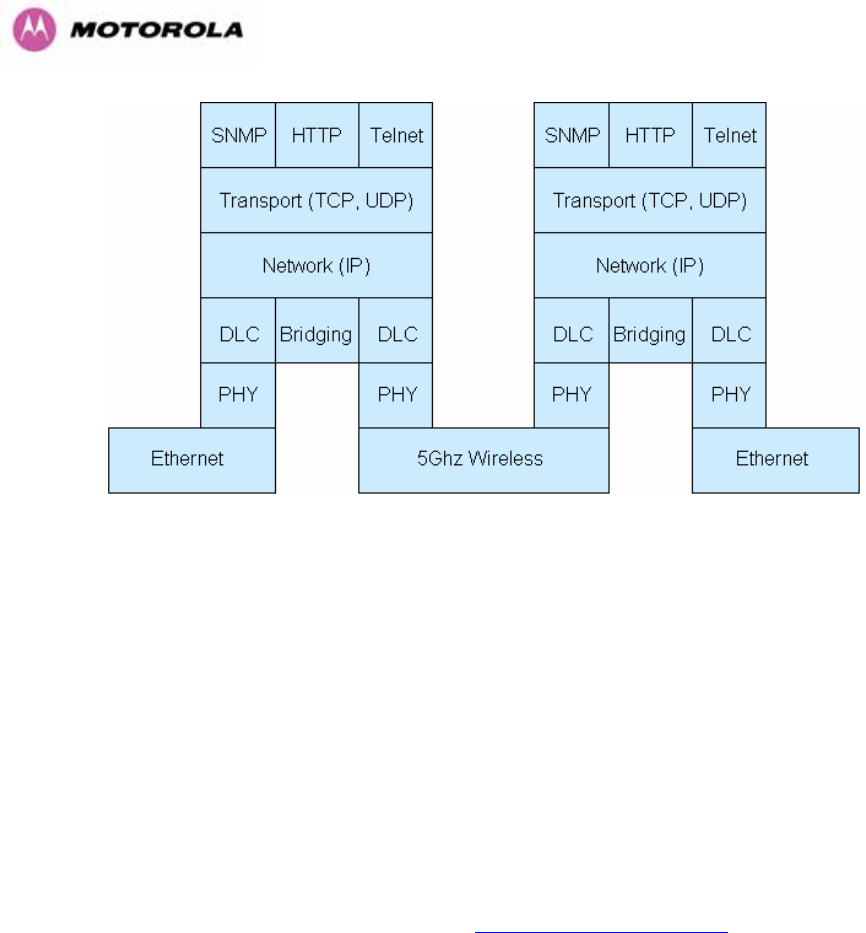
42
Figure 12 – PTP 600 Series Bridge Layer Diagram
The PTP 600 Series Bridge functionality has been extended to encompass the specification
IEEE 802.1p. IEEE 802.1p uses Ethernet packets extended by 4 bytes, as specified in IEEE
802.1q for VLAN tagging, to prioritize packets over the wireless interface. The PTP 600
Series Bridge will forward all VLAN tagged packets regardless of the VLAN ID value.
Each unit in the link is manageable through an IP connection. Standard IP protocols are
utilized for all management functions e.g. HP, SNMP, etc. The unit can be configured to use
VLAN tags on the management interfaces.
The PTP 600 Series Bridge is fully software upgradeable. New software images are first
downloaded from the Motorola website http://www.motorola.com/ptp to a convenient
computer. The image is then uploaded to the ODU via the web management page described
in Section 8.3.6 “Software Upgrade”. The compressed image is first loaded into RAM and
check-summed. If the compressed image transfer has completed successfully the image is
decompressed and written to flash memory. On completion of this process the unit can be
rebooted to use the newly uploaded image. Should this process fail, the unit will revert to a
protected compressed image installed during manufacturing to allow the unit to be recovered.

43
5 General Considerations
5.1 Spectrum Planning
The PTP 600 Series Bridge has three frequency variants in its product range.
Band Definition Frequency
Coverage
Variable
Channel
Width
Channel
Raster
2.5 GHz FCC BRS-EBS Post-
Transition Band
2496-2568 MHz
2572-2614 MHz
2618-2690 MHz
5, 10, 15 and
30 MHz6 for
Lower, Middle
and Upper
bands
5.5 MHz
6 MHz
5.5 MHz
5.4 GHz ETSI 5 GHz band B, USA
UNII Band
5470-5725 MHz
5470-5725 MHz
5,10,15 MHz
30 MHz
6 MHz
10 MHz
5.8 GHz USA ISM Band / ETSI 5 GHz
band C
5725-5850 MHz
5725-5850 MHz
5,10,15 MHz,
30 MHz
6 MHz
10 MHz
Table 5 - PTP 600 Series Bridge Frequency Variants
6 30 MHz channel widths are available where allowed by local regulations and subject to some
restrictions on channel choice.

44
There are two distinct approaches to spectrum planning:
• First an operator can utilize the default spectrum management mode i-DFS
(intelligent Dynamic Frequency Selection). This mode uses the PTP 600 Series
Bridge ability to measure the interference levels in all channels to build up a picture of
the interference / noise levels in all channels. The PTP 600 Series Bridge uses
statistical techniques to select the most appropriate transmit and receive channels. I-
DFS can be influenced in its channel decision process by selectively barring channels
from use. The use of this functionality is described in detail in Section 8.3.7
“Spectrum Management”.
• Second, when detailed control of the spectrum allocation is required, it is
recommended that the fixed frequency mode is used to statically allocate transmit
and receive channels.

45
5.2 Region Codes
The PTP 600 Series Bridge uses a system of Region Codes to control the operation of the
radio link. The Region Code is set by a License Key.
WARNING To meet the regulatory requirements of your region you should set the correct
Region Code by obtaining a new License Key from your reseller or distributor.
Region
Code
Frequency
Band
Regulations /
Countries
Max Tx
Power
EIRP
Limit
Operational
Restrictions
(see Section 5.3)
1 5.8 GHz FCC Compliant
(e.g. USA,
Canada, Taiwan,
Brazil)
25dBm None Reduced TX Power at
Band Edges see Section
5.6.2 “Transmit Power
Reduction at the Band
Edges”
2 5.8 GHz China 10dBm 33dBm
3 5.8 GHz Australia , Hong
Kong
13dBm 36dBm
4 5.8 GHz UK 13dBm 36dBm Radar and RTTT (Road
Transport and Traffic
Telematics, 5795 to
5815 MHz) Radar
Avoidance Enabled
5 5.8 GHz Singapore -3dBm 20dBm
6 5.8 GHz Eire 10dBm 33dBm
7 5.8 GHz Unregulated 25dBm 53dBm Radar and RTTT (Road
Transport and Traffic
Telematics, 5795 to
5815 MHz) Radar
Avoidance Enabled
8 5.4 / 5.8
GHz
Unregulated
/Internal Use
25dBm None
11 5.4 GHz Korea 20dBm 43dBm Band restricted : 5725
MHz to 5825 MHz

46
Region
Code
Frequency
Band
Regulations /
Countries
Max Tx
Power
EIRP
Limit
Operational
Restrictions
(see Section 5.3)
12 5.4 GHz ETSI, USA 7dBm 30dBm Radar Avoidance Enabled
13 5.4 GHz Australia,
Canada
7dBm 30dBm Radar Avoidance Enabled;
Weather Radar Band
(5600 to 5650MHz) barred
16 2.5 GHz USA 23dBm >=63dBm7Licensed Band operation
19 5.8 GHz India 13dBm 36dBm 5.825MHz to 5.850MHz
Only
20 5.4 / 5.8
GHz
Thailand 7 dBm 30 dBm Fixed Power for all
bandwidths.
21 5.4 GHz Korea 30 dBm
(Max Band)
17 dBm Maximum Channel
Bandwidth 20 MHz. 5470
MHz to 5650 MHz only.
Table 6 – PTP 600 Series Bridge Region Code Definitions
When shipped from the factory units8 are configured as follows:
• PTP 600 Series Bridge 2.5 GHz – Region Code 16
• PTP 600 Series Bridge 5.4 GHz – Region Code 129
• PTP 600 Series Bridge 5.8 GHz – Region Code 1
7 The EIRP limit is approximately 63dBm + 10 x Log(360/Antenna Azimuth BW)
8 Note that 2.5 GHz, 5.8GHz and 5.4GHz are different products.
9 Note that the Quickstart Guide also contains the license keys for region 10. This bars operation in
the Band 5600 – 5650 MHz and MUST be used for equipment deployed in Canada and Australia.

47
5.3 Operational Restrictions
5.3.1 Radar Avoidance
Radar Avoidance requires that equipment used in the region:
• Detects interference from other systems and avoids co-channel operation with these
systems, notably radar systems.
• Provide on aggregate a uniform loading of the spectrum across all devices, i.e. Fixed
Frequency operation is not allowed.
• Radar avoidance is not applicable to the PTP25600 product.
To address the primary aims the Spectrum Management algorithm implements a radar
detection function which looks for impulsive interference on the active channel only. If
impulsive interference is detected Spectrum Management will mark the current active channel
as having detected radar and initiate a channel hop to an available channel. The previous
active channel will remain in the radar detected state for thirty minutes after the last impulsive
interference pulse was detected. After the thirty minutes have expired the channel will be
returned to the available channel pool.
The radar detection algorithm will always scan the active channel for 60 seconds for radar
interference before using the channel. This compulsory channel scan will mean that there is a
60 seconds service outage every time radar is detected and that the installation time is
extended by 60 seconds even if there is found to be no radar on the channel.
NOTE: On system installation or start-up this extends the initial scan time of the Master unit
by 60 seconds. To address the “provide aggregate uniform loading of the spectrum across all
devices” requirement, the channel selection algorithm will choose a channel at random from a
list of available channels. The channel selection algorithm is initiated at link initialization and
when radar interference is detected.
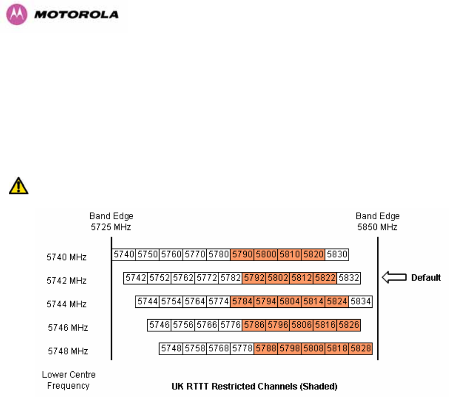
48
5.3.2 RTTT Avoidance and Other Channel Use Restrictions
Where regulatory restrictions apply to certain channels these channels are barred. The user
should note that the number of channels barred is dependant on the channel raster selected.
For example see the effect of the UK RTTT channel restrictions in Figure 13. Barred channels
are indicated by a “No Entry” symbol displayed on the “Spectrum Management” web page,
see Section 8.3.9 “Spectrum Management Control - With Operational Restrictions”.
NOTE: “Radar Avoidance Enabled” is only valid with 30 MHz channel bandwidth.
Figure 13 - 5.8 GHz UK RTTT Channel Avoidance – 30 MHz Channel Bandwidth Only

49
5.3.3 Radar Avoidance, i-DFS and Variable (Narrow) Bandwidth Operation
PTP 600 Series bridges do not support operation with 5, 10 or 15 MHz channel bandwidth in
regions where radar avoidance is enabled.
NOTE: Radar avoidance requirements in the 5.4GHz band in the EU is detailed in
specification EN 301-893 version 1.3.1 and in the US in the specification FCC part 15.437.
Radar avoidance at 5.8GHz is applicable to EU operation and the requirements are currently
as defined in EN 301 893 version 1.3.1.
5.4 Variable Channel Bandwidth Operation
Channel bandwidths of 5, 10, 15 and 30MHz10 are supported for Full versions of the PTP
600. Lite versions of the PTP 600 products support only channel bandwidths of 10, 15 and 30
MHz.
Configuration of the variable bandwidth operation must be symmetric, i.e. the Transmit and
receive channels must use identical channel bandwidths.
NOTE: Hence, narrow bandwidth modes may not be used in regions where Radar Avoidance
is mandatory.
5.5 2.5GHz Specific Frequency Planning Considerations
The supported 2.5GHz frequency range is split into three bands, according to the bands
specified in the FCC BRS-EBS Post-Transition Band plan11:
• Lower: 2496 MHz to 2572 MHz with a 5.5MHz channel raster (76 MHz total).
• Middle: 2572 MHz to 2614 MHz with a 6 MHz channel raster (42 MHz total).
• Upper: 2618 MHz to 2690 MHz with a 5.5 MHz channel raster (76 MHz total).
NOTE: When configured for 2.5 GHz operation, the unit will only operate in Fixed Frequency
mode, and the user is unable to select i-DFS.
10 30MHz channel widths are available where allowed by local regulations and subject to some
restrictions on channel choice.
11 Only for Region Code 16

50
The 2.5 GHz product variant support channel centre frequencies as specified in Table 7.
Block Channel
Bandwidth
(MHz)
Channel Centre Frequencies (MHz)
5 2499.25, 2504.75, 2510.25, 2515.75, 2521.25, 2526.75, 2532.25, 2537.75,
2543.25, 2548.75, 2554.25, 2559.75, 2565.25
10 2502, 2507.5, 2513, 2518.5, 2524, 2529.5, 2535, 2540.5, 2546, 2551.5, 2557,
2562.5
15 2504.75, 2510.25, 2515.75, 2521.25, 2526.75, 2532.25, 2537.75, 2543.25,
2548.75, 2554.25, 2559.75
Lower
Band
Segment
30 2513, 2524, 2535, 2546
5 2575, 2581, 2587, 2593, 2599, 2605, 2611
10 2578, 2584, 2590, 2596, 2602, 2608
15 2581, 2587, 2593, 2599, 2605
Middle
Band
Segment
30 Not supported
5 2626.75, 2632.25, 2637.75, 2643.25, 2648.75, 2654.25, 2659.75, 2665.25,
2670.75, 2676.25, 2681.75, 2687.25
10 2629.5, 2635, 2640.5, 2646, 2651.5, 2657, 2662.5, 2668, 2673.5, 2679, 2684.5
15 2632.25, 2637.75, 2643.25, 2648.75, 2654.25, 2659.75, 2665.25, 2670.75,
2676.25, 2681.75
Upper
Band
Segment
30 2640.5, 2651.5, 2662.5, 2673.5
Table 7 - 2.5 GHz Product Variant Channel Plan - FCC BRS-EBS Post-Transition Band
The channel centre frequencies listed above have been selected to align with the so-called
post-transition BRS channels as shown in Figure 14.
NOTE: The 2.5 GHz frequency variant supports three portions of the BRS spectrum
allocation. These are configurable at installation and constrain the wireless to operate in a
limited portion of the RBS spectrum. The three frequency bands are as shown in Figure 14:
Band 1: channels A, B, C and D (16.5 MHz blocks)
Band 2: channels A through G (6 MHz blocks)
Band 3: channels E, F, G and H (16.5 MHz blocks)
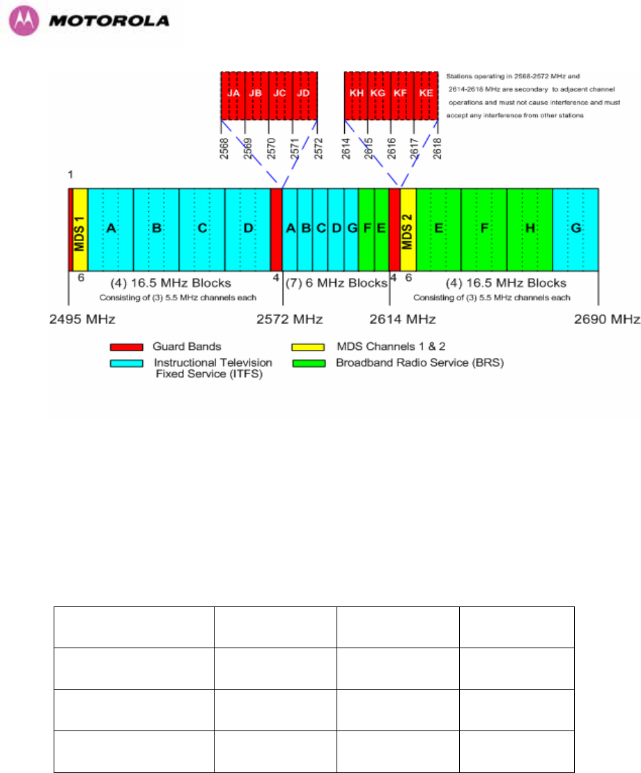
51
Figure 14 - 2.5 GHz BRS Band Channel Assignments
5.5.1 Power Reduction in the Upper Band
Operation in the Upper Band Segment (Table 8 - Power Reduction in the Upper Band) will
result in a lower maximum transmit power and the reduction depends on the channel
bandwidth. The maximum power levels produced are shown below
Band 15MHz Channel 10MHz Channel 5MHz Channel
Lower Band Segment 23dBm 23dBm 23dBm
Middle Band Segment 23dBm 23dBm 23dBm
Upper Band Segment 23dBm 22dBm 21dBm
Table 8 - Power Reduction in the Upper Band
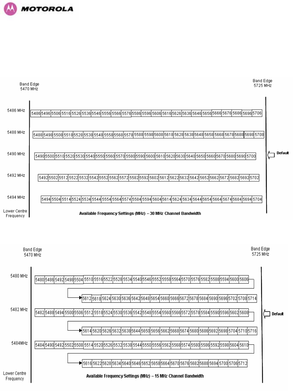
52
5.6 5.4GHz Specific Frequency Planning Considerations
Adjustment of the lower centre frequency allows the operator to slide the available frequency settings
up and down the 5.4 GHz band. See Figure 15 to Figure 18.
Figure 15 - 5.4 GHz Available Spectrum Settings - 30 MHz Channel Bandwidth
Figure 16 - 5.4 GHz Available Spectrum Settings - 15 MHz Channel Bandwidth
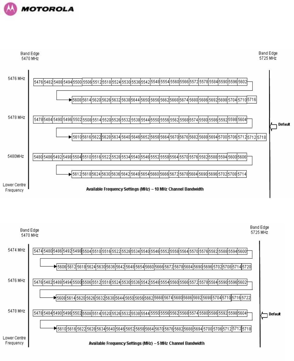
53
Figure 17 - 5.4 GHz Available Spectrum Settings - 10 MHz Channel Bandwidth
Figure 18 - 5.4 GHz Available Spectrum Settings - 5 MHz Channel Bandwidth
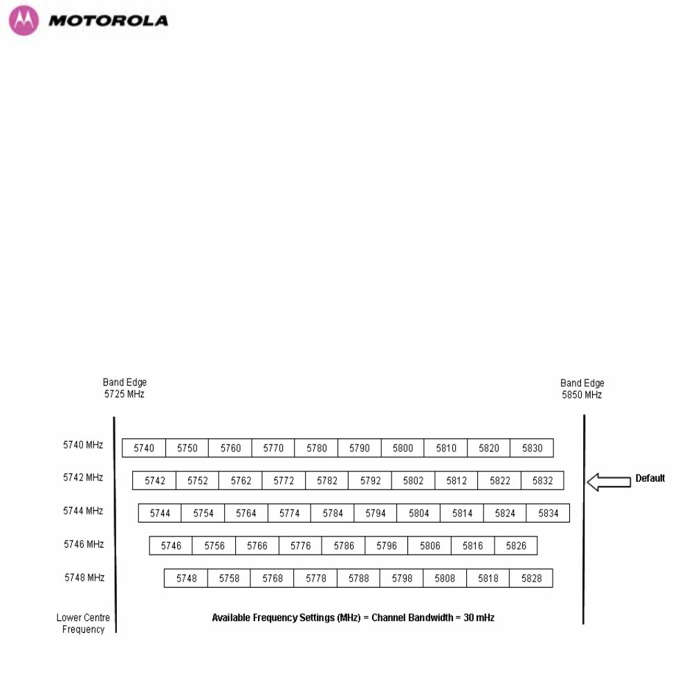
54
5.6.1 Raster Considerations
The PTP 600 Series Bridge 5.4 GHz variant operates on a 10 MHz channel raster (for 30 MHz
channel bandwidth) and 6 MHz for the variant channel bandwidths 5, 10 and 15 MHz. The channel
raster is set to even centre frequencies. See Figure 15 to Figure 18.
5.6.2 Transmit Power Reduction at the Band Edges
The 5.4 GHz product variant does not apply any band edge power reduction.
5.7 5.8GHz Specific Frequency Planning Considerations
Adjustment of the lower center frequency allows the operator to slide the available frequency
settings up and down the 5.8 GHz bands. Figure 19 to Figure 22 show the available spectrum
depending on the channel width (30 MHz, 15 MHz, 10 MHz and 5 MHz respectively).
Figure 19 - 5.8 GHz Available Spectrum Settings – 30 MHz Channel Bandwidth
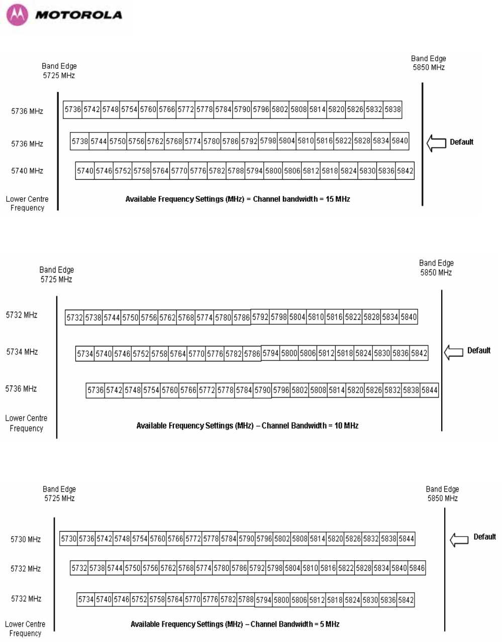
55
Figure 20 - 5.8 GHz Available Spectrum Settings - 15 MHz Channel Bandwidth
Figure 21 - 5.8 GHz Available Spectrum Settings - 10 MHz Channel Bandwidth
Figure 22 - 5.8 GHz Available Spectrum Settings - 5 MHz Channel Bandwidth

56
5.7.1 Raster Considerations
The PTP 600 Series Bridge 5.8 GHz variant operates on a 10 MHz channel raster (for 30
MHz channel bandwidth) and 6 MHz for the variant channel bandwidths 5, 10 and 15 MHz.
The channel raster is set to even center frequencies. See Figure 19 to Figure 22.
5.7.2 Transmit Power Reduction at the Band Edges
Operation at or near the 5.8 GHz band edges can results in a lower maximum transmit power.
In some configurations the PTP 600 Series Bridge solution reduces the power when
operating at the edge channels. The amount of reduction, if any, is dependant on the region
code of the region of operation. This currently only affects systems configured with Region
Code 1.
The power reduction in the edge channels for 5 MHz, 10 MHz and 15 MHz is presented in
Table 9 (for region code 1 ONLY).
Power levels
Channel
Centre
5728 5730 5732 5734 5736 5738-
5836
5838 5840 5842 5844 5846
Channel
Width
5 19 25 25 25 25 25 25 25 25 25 23
10 N/A N/A 23 25 25 25 25 25 23 19 N/A
15 N/A N/A N/A 19 23 25 25 23 19 N/A NA
Table 9 - 5.8 GHz Band Edge Tx Power Reduction –
Channel Bandwidth 5, 10, 15 MHz Only
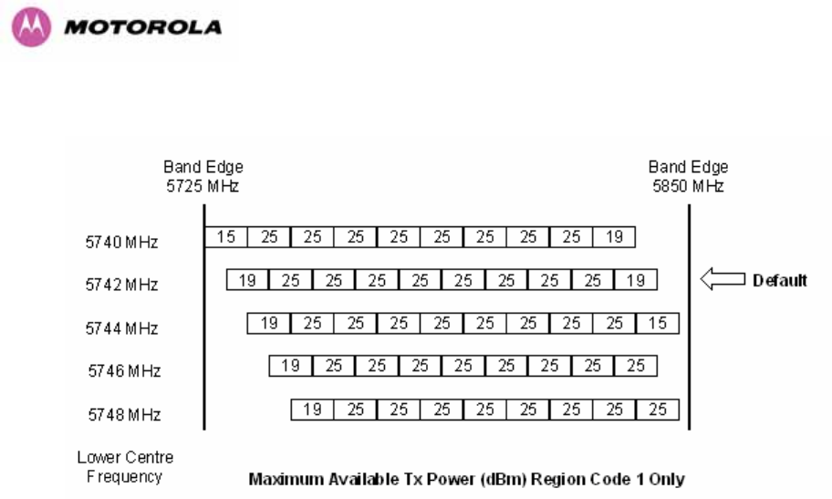
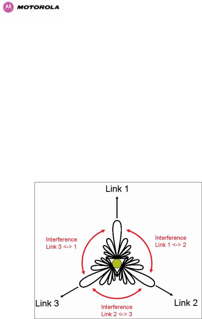
58
5.8 Time Division Duplex (TDD) Synchronization
5.8.1 Introduction
In situations where a number of units are installed on the same mast, it is possible that the
performance or throughput of some of the links is reduced and in some cases a number of
these links may not even work at all. This is due to the interference between the units and the
levels of this type of interference can be worse when the links are operating on the same or
adjacent channels. This is also a situation that can arise in large and dense networks with a
large number of links installed.
The effect of this cross-interference between the units can be reduced by ensuring that the
units are in “synchronism”, i.e. synchronize transmit and receive frames of the units so they
do not interfere with each other. The benefit of that is that many units can be installed on the
same mast without taking precautions for angular/spatial separation and possible antenna
changes to solve the interference problem.
Figure 24 shows a simple example of cross-interference when three links of three different
link lengths mounted on a mast operating on the same or adjacent channels.
Figure 24 - Co-location of Links Interference Problem - A Simple Example

59
5.8.2 TDD Synchronization
The TDD synchronization feature introduces a fixed TDD framing mode, and allows frame
timing in a PTP link to be synchronized with an external reference. This means that all links in
a network may be made to transmit and receive in synchronism, implying reduced RF
interference between links.
5.8.3 Deployment Consideration
The following are deployment considerations:
• Fixed frequency operation ONLY
• Fixed TDD operation only, i.e. all synchronized links have same ratio master to slave.
• Not presently available when radar avoidance is enabled.
• Networks need to be carefully planned
5.8.4 PTP Approach for Using TDD Synchronization
The external timing reference will consist of a precise 1 Hz signal, synchronized in both phase
and frequency with a global (or at least network-wide) master. The master clock will be
provided by one GPS receiver per link. The GPS link will be fitted between the lightning
protection unit and the ODU.
The TDD frame structure will depend on primary characteristics of the overall network such
as the longest link and the maximum distance between interfering master and slave ODUs.
The ODU web management page contains an extension to the existing link installation wizard
to compute frame timings from these primary characteristics. The ODU additionally provides
an “expert mode” permitting frame timing details to be entered directly.
See Section 14 for TDD Synchronization installation and configuration guidelines.
5.9 Distance
The PTP 600 Series Bridge will operate at ranges from 100 m (330 ft) to 200 km (124 miles),
within 3 modes: 0-40km (0-25 miles), 0-100km (0-62 miles) and 0-200km (0-124 miles).
Operation of the system will depend on obstacles in the path between the units. Operation at
40 km (25 miles) or above will require a near line-of-sight path. Operation at 100m (330 ft)
could be achieved with one unit totally obscured from the other unit, but with the penalty of

60
transmitting at higher power in a non-optimal direction, thereby increasing interference in the
band. This subject is covered in more detail in Section 6.1.3 “Path Loss Considerations“.
5.10 Networking Information
The PTP 600 Series Bridge operates as a transparent Ethernet bridge. Each unit requires an
IP address. This IP address is for management purposes only and it plays no part in the
operation of the system. IP addresses are assigned during initial configuration as described in
Section 7.2 “Installation Procedure”.
5.11 Lightning Protection
The amount of lightning protection is dependent on regulatory requirements and the end user
requirements. The standard ODU for the PTP 600 Series Bridge is fitted with surge limiting
circuits and other features to minimize the risk of damage due to nearby lightning strikes.
These standard features may require some additional equipment to be configured as part of
the system installation to be fully effective. Motorola recommends the use of screened cable
and a surge arrestor to protect connected equipment from nearby strikes.
NOTE: The PTP 600 Series Bridge is not designed to survive direct lightning strikes. For this
reason the unit should not be installed as the highest point in a localized area, unless specific
precautions are taken. See Section 11 “Lightning Protection”.
5.12 Electrical Requirements
The PTP 600 Series Bridge is supplied with a variable input voltage (100-240V, 47-63Hz AC)
inline power supply unit which is incorporated into the Power Indoor Unit (PIDU Plus). The
PTP 600 Series Bridge requires one mains supply outlet at each end of the link.

61
6 Site Planning
6.1 Site Selection Criteria
The following are guidelines for selecting the installation location of the ODU and PDU Plus
for a PTP 600 Series Bridge.
6.1.1 ODU Site Selection
When selecting a site for the ODU the following should be taken into consideration:
• It is not possible for people to stand or walk inadvertently in front of the antenna
• Height and location to achieve the best radio path
• Height in relation to other objects with regard to lightning strikes
• Protection from the weather
• Aesthetics and planning permission issues
• Distance from the ODU and connected Network equipment (Maximum cable run from the
ODU to the connected equipment is 100m [330 ft])
• Distance from the PIDU Plus to the ODU (Maximum cable run from the PIDU Plus to the
ODU is 100m [330 ft] when using the 1000BaseT interface)
• If using the GPS Sync Box, ensure that it is exposed to an unobstructed path to the sky.
Please refer to the “GPS Sync Box Kit” User Manual available in your installation CD.
6.1.2 PTP 600 Series Bridge PIDU Plus Site Selection
When selecting a site for the PIDU Plus the following should be taken into consideration:
• Availability of a mains electricity supply
• Accessibility for viewing status indicators and pressing reset switch (See Section 3.3.2
and Section 10)

62
6.1.3 Path Loss Considerations
The path loss is the amount of attenuation the radio signal undergoes between the two ends
of the link. The path loss is the sum of the attenuation of the path if there were no obstacles in
the way (Free Space Path Loss), the attenuation caused by obstacles (Excess Path Loss)
and a margin to allow for possible fading of the radio signal (Fade Margin).
capabilityseasonalfadeexcessspacefree LLLLL
<
+
+
+
_
Where
spacefree
L_ Free Space Path Loss (dB)
excess
L Excess Path Loss (dB)
fade
L Fade Margin Required (dB)
seasonal
L Seasonal Fading (dB)
capability
L Equipment Capability (dB)
Equation 1 - Path Loss
6.1.4 Definitions
Sensitivity: Sensitivity is defined as the combined receive input signal level on both horizontal
and vertical inputs that produces a Null BER Error ratio of 3x10⁻⁷.
Output Power: The output power shown is for a centre channel in Region 1. The output power
will be reduced on the edge channels and may vary if different region codes are selected.
AMOD Threshold: The AMOD threshold is the combined receive input signal level on both
horizontal and vertical inputs that results in the link consistently entering the receive
modulation mode under consideration as the signal level is increased.
System Threshold: Thresholds for all modes except BPSK are for the relevant link
optimization AMOD thresholds. System threshold for BPSK is the RPSK receive sensitivity.
Max Link Loss: The maximum link loss for each modulation mode is derived from the AMOD
threshold for that mode (sensitivity threshold for BPSK) and the maximum Region 1 centre
channel output power. The figures assume integral antennas with 23 dBi gain are used.
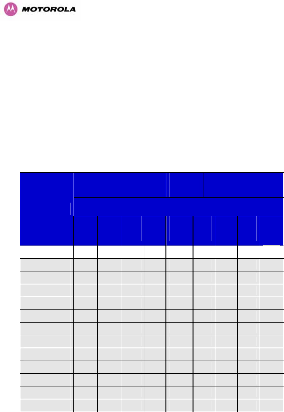
63
6.1.5 2.5 GHz Product Variant - Link Loss, Output Power and System Threshold versus Modulation
Mode
The equipment capability is given in Table 10 (IP Mode) and Table 12 (TDM Mode). Each
table gives Link Loss, Output Power and System Thresholds for PTP 600 Series Bridge in all
modulation modes for all channel bandwidths (5 MHz, 10 MHz, 15 MHz and 30 MHz).
Adaptive Modulation will ensure that the highest throughput that can be achieved
instantaneously will be obtained taking account of propagation and interference. The
calculation of Equation 1 needs to be performed to judge whether a particular link can be
installed. When the link has been installed, web pages provide information about the link loss
currently measured by the equipment both instantaneously and averaged. The averaged
value will require maximum seasonal fading to be added, and then the radio reliability of the
link can be computed.
Threshold
V
alue
(
dBm
)
Output
Power
Maximum
Link Loss
(
dB
)
Channel Bandwidth (MHz)
Modulation Mode
5
MHz
10
MHz
15
MHz
30
MHz
All
Bands
5
MHz
10
MHz
15
MHz
30
MHz
BPSK 0.63 single -97.95 -95.03 -91.36 -90.09 +23 157.0 154.0 150.4 149.1
QPSK 0.63 single -94.11 -92.39 N/A -86.97 +23 153.1 151.4 N/A 146.0
QPSK 0.87 single -90.95 -88.55 N/A -83.61 +23 150.0 147.5 N/A 142.6
16QAM 0.63 single -89.04 -86.49 N/A -81.39 +23 148.0 145.5 N/A 140.4
16QAM 0.63 dual -85.86 -83.41 N/A -78.45 +23 144.9 142.4 N/A 137.4
16QAM 0.87 single -83.74 -80.42 N/A -75.90 +23 142.7 139.4 N/A 134.9
16QAM 0.87 dual -79.91 -77.12 N/A -72.13 +23 138.9 136.1 N/A 131.1
64QAM 0.75 single -80.68 N/A N/A -72.81 +23 139.7 N/A N/A 131.8
64QAM 0.75 dual -77.11 -70.11 N/A -69.30 +23 136.1 129.1 N/A 128.3
64QAM 0.92 single -78.19 N/A N/A -70.63 +23 137.2 N/A N/A 129.6
64QAM 0.92 dual -75.42 -63.39 N/A -67.33 +23 134.4 122.4 N/A 126.3
256QAM 0.81 single -75.91 N/A N/A -68.39 +23 134.9 N/A N/A 127.4
256QAM 0.81 dual -72.85 -63.19 N/A -64.82 +23 131.9 122.2 N/A 123.8
Table 10 - 2.5GHz- IP Mode – Loss, Output Power and System Threshold Vs Modulation Mode
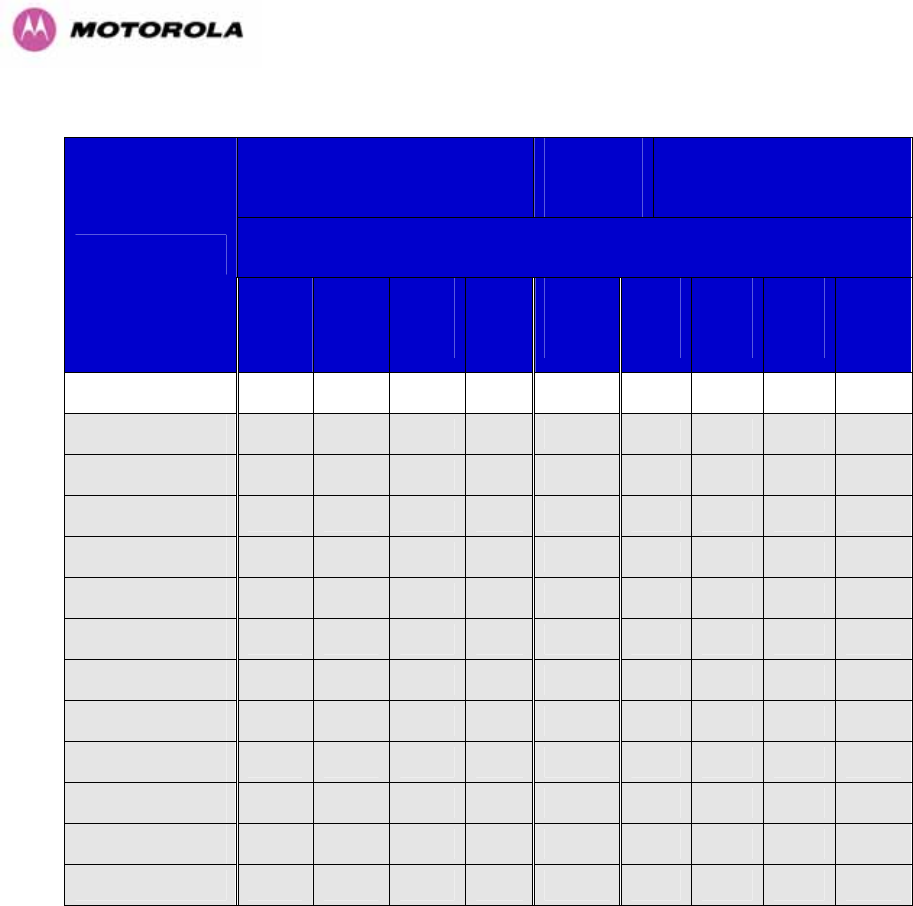
64
Threshold
V
alue
(
dBm
)
Output
Power
Maximum
Link Loss
(
dB
)
Channel Bandwidth (MHz)
Modulation Mode
5
MHz
10
MHz
15
MHz
30
MHz
All
Bands
5
MHz
10
MHz
15
MHz
30
MHz
BPSK 0.63 single -97.95 -95.03 -91.36 -90.09 +23 157.0 154.0 150.4 149.1
QPSK 0.63 single -91.23 -89.07 -85.17 -84.52 +23 150.2 148.1 144.2 143.5
QPSK 0.87 single -87.99 -84.85 -81.06 -80.57 +23 147.0 143.8 140.1 139.6
16QAM 0.63 single -85.64 -82.79 -79.20 -78.50 +23 144.6 141.8 138.2 137.5
16QAM 0.63 dual -83.05 -79.60 -76.21 -75.55 +23 142.0 138.6 135.2 134.6
16QAM 0.87 single -80.51 -77.28 -73.28 -72.64 +23 139.5 136.3 132.3 131.6
16QAM 0.87 dual -77.22 -73.21 -70.08 -69.14 +23 136.2 132.2 129.1 128.1
64QAM 0.75 single -77.53 -73.70 -70.38 -69.72 +23 136.5 132.7 129.4 128.7
64QAM 0.75 dual -74.31 -70.11 -67.01 -66.11 +23 133.3 129.0 126.0 125.1
64QAM 0.92 single -75.09 -71.09 -68.62 -67.90 +23 134.1 130.1 127.6 126.9
64QAM 0.92 dual -72.45 -67.12 -65.19 -64.30 +23 131.4 126.1 124.2 123.3
256QAM 0.81 single -72.25 -71.10 -65.50 -64.58 +23 131.3 130.1 124.5 123.6
256QAM 0.81 dual -69.40 -66.87 -62.24 -60.53 +23 128.4 125.9 121.2 119.5
Table 11 - 2.5GHz- TDM Mode – Loss, Output Power and System Threshold Vs Modulation
Mode

65
6.1.6 5.4 GHz Product Variant - Link Loss, Output Power and System Thresholds versus
Modulation Mode
The equipment capability is given in Table 12 (IP Mode) and Table 13 (TDM Mode). Each
table gives Link Loss, Output Power and System Thresholds for PTP 600 Series Bridge in all
modulation modes for all channel bandwidths (5 MHz, 10 MHz, 15 MHz and 30 MHz). The
values for System Thresholds are typical values in a flat radio channel for an Ethernet frame
loss rate of 3E-5. For minimum error rates on TDM links the maximum modulation mode
should be limited to 64QAM 0.75.
The un-shaded value above (BPSK) is a static receive sensitivity measurement. The shaded
values above are static receive sensitivity measurements with an AMOD threshold applied.
The AMOD threshold applied is for a benign radio channel.
Threshold
V
alue
(
dBm
)
Output
Power
Maximum
Link Loss
(
dB
)
Channel Bandwidth (MHz)
Modulation Mode
5
MHz
10
MHz
15
MHz
30
MHz
All
Bands
5
MHz
10
MHz
15
MHz
30
MHz
BPSK 0.63 single -95.05 -94.58 -92.26 -88.90 +25 170.2 166.6 164.3 160.9
QPSK 0.63 single N/A N/A -89.21 -85.94 +24 N/A N/A 160.2 156.9
QPSK 0.87 single N/A N/A -85.74 -82.37 +23 N/A N/A 155.7 152.4
16QAM 0.63 single N/A N/A -83.58 -80.07 +22 N/A N/A 152.6 149.1
16QAM 0.63 dual N/A N/A -79.91 -77.04 +22 N/A N/A 148.9 146.0
16QAM 0.87 single N/A N/A -78.97 -75.92 +20 N/A N/A 146.0 142.9
16QAM 0.87 dual N/A N/A -75.22 -71.78 +20 N/A N/A 142.2 138.8
64QAM 0.75 single N/A N/A -75.74 -73.02 +18 N/A N/A 140.7 138.0
64QAM 0.75 dual N/A N/A -72.15 -68.61 +18 N/A N/A 137.2 133.6
64QAM 0.92 single N/A N/A -71.15 -67.55 +18 N/A N/A 136.2 132.6
64 QAM 0.92 dual N/A N/A -67.17 -63.92 +18 N/A N/A 132.2 128.9
256QAM 0.81 single N/A N/A N/A -65.36 +18 N/A N/A N/A 130.4
256QAM 0.81 dual N/A N/A N/A -60.95 +18 N/A N/A N/A 126.0
Table 12 – 5.4GHz - IP Mode - Link Loss, Output Power, System Threshold Vs Modulation
Mode
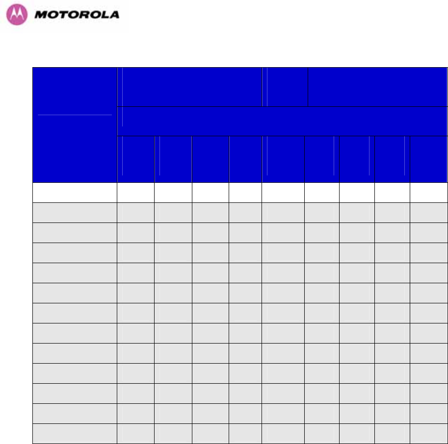
66
Threshold
V
alue
(
dBm
)
Output
Power
Maximum
Link Loss
(
dB
)
Channel Bandwidth (MHz)
Modulation Mode
5
MHz
10
MHz
15
MHz
30
MHz
All
Bands
5
MHz
10
MHz
15
MHz
30
MHz
BPSK 0.63 single -98.24 -94.58 -92.26 -88.90 +25 169.2 165.6 163.3 159.9
QPSK 0.63 single -89.70 -88.28 -86.35 -81.35 +24 159.7 158.3 156.4 151.4
QPSK 0.87 single -86.70 -84.30 -82.34 -78.42 +23 155.6 153.3 151.3 147.4
16QAM 0.63 single -86.56 -81.81 -79.91 -75.99 +22 151.7 149.8 147.9 144.0
16QAM 0.63 dual -83.70 -78.23 -76.54 -72.41 +22 148.8 146.3 144.5 140.4
16QAM 0.87 single N/A N/A -75.47 N/A +20 N/A N/A 141.5 N/A
16QAM 0.87 dual -76.92 -73.85 -72.19 -68.70 +20 142.9 139.9 138.2 134.7
64QAM 0.75 single N/A N/A -71.77 N/A +18 N/A N/A 135.8 N/A
64QAM 0.75 dual -73.00 -70.41 -68.79 -65.63 +18 137.0 134.4 132.8 129.6
64QAM 0.92 single N/A N/A -67.40 N/A +18 N/A N/A 131.4 N/A
64 QAM 0.92 dual -68.15 -65.62 -64.23 -60.50 +18 132.1 129.6 128.2 124.5
256QAM 0.81 single N/A N/A N/A -65.36 +18 N/A N/A N/A N/A
256QAM 0.81 dual N/A N/A N/A -60.50 +18 N/A N/A N/A 124.5
Table 13 – 5.4GHz -TDM Mode - Link Loss, Output Power, System Threshold Vs Modulation
Mode

67
6.1.7 5.8 GHz Product Variant - Link Loss, Output Power and System Thresholds versus
Modulation Mode
The equipment capability is given in Table 14 (IP Mode) and Table 15 (TDM Mode). Each
table gives System Thresholds, Link Loss and Output Power for PTP 600 Series Bridge in all
modulation modes for all channel bandwidths (5MHz, 10MHz, 15 MHz and 30 MHz). The
values for System Thresholds are typical values in a flat radio channel for an Ethernet frame
loss rate of 3E-5. For minimum error rates on TDM links the maximum modulation mode
should be limited to 64QAM 0.75.
The un-shaded value above (BPSK) is a static receive sensitivity measurement. The shaded
values above are static receive sensitivity measurements with an AMOD threshold applied.
The AMOD threshold applied is for a benign radio channel.
Threshold
V
alue
(
dBm
)
Output
Power
Maximum
Link Loss
(
dB
)
Channel Bandwidth (MHz)
Modulation Mode
5
MHz
10
MHz
15
MHz
30
MHz
All
Bands
5
MHz
10
MHz
15
MHz
30
MHz
BPSK 0.63 single -95.05 -92.51 -90.78 -86.33 +25 166.1 163.5 161.8 157.3
QPSK 0.63 single -91.86 -90.04 -87.73 -83.00 +24 161.9 160.0 157.7 153.0
QPSK 0.87 single -88.69 -86.64 -84.84 -80.26 +23 157.7 155.6 153.8 149.3
16QAM 0.63 single -85.99 -84.31 -82.44 -78.34 +22 154.0 152.3 150.4 146.3
16QAM 0.63 dual -83.46 -80.36 -78.51 -75.34 +22 151.5 148.4 146.5 143.3
16QAM 0.87 single -82.12 -79.50 -78.13 -72.47 +20 148.1 145.5 144.1 138.5
16QAM 0.87 dual -79.24 -76.21 -73.92 -71.49 +20 145.2 142.2 139.9 137.5
64QAM 0.75 single -78.82 -76.70 -75.20 -69.16 +18 142.8 140.7 139.2 133.2
64QAM 0.75 dual -76.14 -73.14 -70.99 -67.67 +18 140.1 137.1 135.0 131.7
64QAM 0.92 single -74.40 -72.48 -66.24 -64.98 +18 138.4 136.5 134.6 129.0
64 QAM 0.92 dual -70.23 -69.07 -70.69 -61.53 +18 134.2 133.1 130.2 125.5
256QAM 0.81 single N/A N/A N/A -64.03 +18 N/A N/A N/A 128.0
256QAM 0.81 dual N/A N/A N/A -59.59 +18 N/A N/A N/A 123.6
Table 14 - 5.8GHz - IP Mode - Link Loss, Output Power, System Threshold Vs Modulation Mode

68
Threshold
V
alue
(
dBm
)
Output
Power
Maximum
Link Loss
(
dB
)
Channel Bandwidth (MHz)
Modulation Mode
5
MHz
10
MHz
15
MHz
30
MHz
All
Bands
5
MHz
10
MHz
15
MHz
30
MHz
BPSK 0.63 single -95.05 -92.51 -90.78 -86.33 +25 166.1 163.5 161.8 157.3
QPSK 0.63 single -88.70 -87.77 -85.95 -80.59 +24 158.7 157.8 155.9 150.6
QPSK 0.87 single -85.51 -83.79 -81.56 -77.82 +23 154.5 152.8 150.6 146.8
16QAM 0.63 single -81.98 -81.26 -79.06 -75.29 +22 150.0 149..3 147.1 143.3
16QAM 0.63 dual -79.40 -77.58 -75.62 -71.72 +22 147.4 145.6 143.6 139.7
16QAM 0.87 single -78.66 -76.32 -74.67 -71.21 +20 144.7 142.3 140.7 137.2
16QAM 0.87 dual -75.05 -73.16 -71.03 -67.73 +20 141.0 139.2 137.0 133.7
64QAM 0.75 single -74.44 -72.26 -70.64 -67.94 +18 138.4 136.3 134.6 131.9
64QAM 0.75 dual -70.90 -69.52 -67.59 -64.02 +18 134.9 133.5 131.6 128.0
64QAM 0.92 single -70.86 -68.01 -66.63 -63.07 +18 134.9 132.0 130.6 127.1
64 QAM 0.92 dual -66.80 -64.62 -65.52 -58.65 +18 130.8 128.6 126.5 122.7
256QAM 0.81 single N/A N/A N/A -63.07 +18 N/A N/A N/A 127.1
256QAM 0.81 dual N/A N/A N/A -58.65 +18 N/A N/A N/A 122.7
Table 15 - 5.8GHz - TDM Mode - Link Loss, Output Power, System Threshold Vs Modulation
Mode

69
7 Installation
Motorola recommends that only qualified personnel undertake the installation of a PTP 600
Series Bridge solution.
7.1 Preparation
Before proceeding with the installation you should:
• Check the contents of all packages against the parts lists shown in the packing list.
• Ensure that you have the correct tools for the job.
• Ensure that you are qualified to undertake the work.
• Ensure that you have taken the correct safety precautions.
• Have completed the site planning as described in Section 6 “Site Planning”.
7.2 Installation Procedure
The 600 Series installation procedure consists of the following steps:
• Mounting the ODUs, Section 7.6
• Connecting up, Section 7.7
• Mounting the PIDU Plus units, Section 7.7.8
• Mounting the Lightning Protection Units, Section 16.
• Mounting the GPS Sync Box (if required), Section 14 and refer to the “GPS Sync Box Kit”
User Manual available in your installation CD for specific information related to the GPS
Sync Box.
• Powering Up, Section
7.7.10
• Aligning the ODUs, Section 7.7.11
7.3 Tools Required
The following specific tools are required to install a PTP 600 Series Bridge in addition to
general tools:
• 13mm Spanner / Wrench
• RJ45 Crimp Tool
• IBM Compatible Personal Computer (PC) running Windows 98 or later with 10, 100 or
1000 BaseT Ethernet (Ability to change IP settings easily is recommended)
• Either Internet Explorer version 6 or higher, or FireFox 1.5 or higher are recommended.
• Ethernet patch cable
• 6mm general purpose crimp tool for the grounding lug (optional for Lightning Protection)

70
7.4 Installation Support
Online installation support and contact details for your regional support can be found at
http://www.motorola.com/ptp
A Frequently Asked Questions (FAQ) section can be found in Section 21.
7.5 Legal Disclaimer
IN NO EVENT SHALL MOTOROLA, INC. BE LIABLE FOR ANY INJURY TO ANY PERSONS
OR ANY DAMAGE CAUSED DURING THE INSTALLATION OF THE MOTOROLA PTP 600
SERIES PRODUCT.
7.6 Mounting the ODUs
The ODU mounting bracket is designed to ease installation by fixing the bracket to a pole and
then bringing the ODU into position using a single bolt fixing. The ODU should be mounted
using the following steps ensuring that the cable entry is at the bottom.
The ODU mounting bracket is design to work with poles with diameters in the range 50mm
(2”) to 75mm (3”).
Step 1: Mount the bracket to the pole. Step 2: Mate the unit to the bracket together
and tighten the nut and bolt.
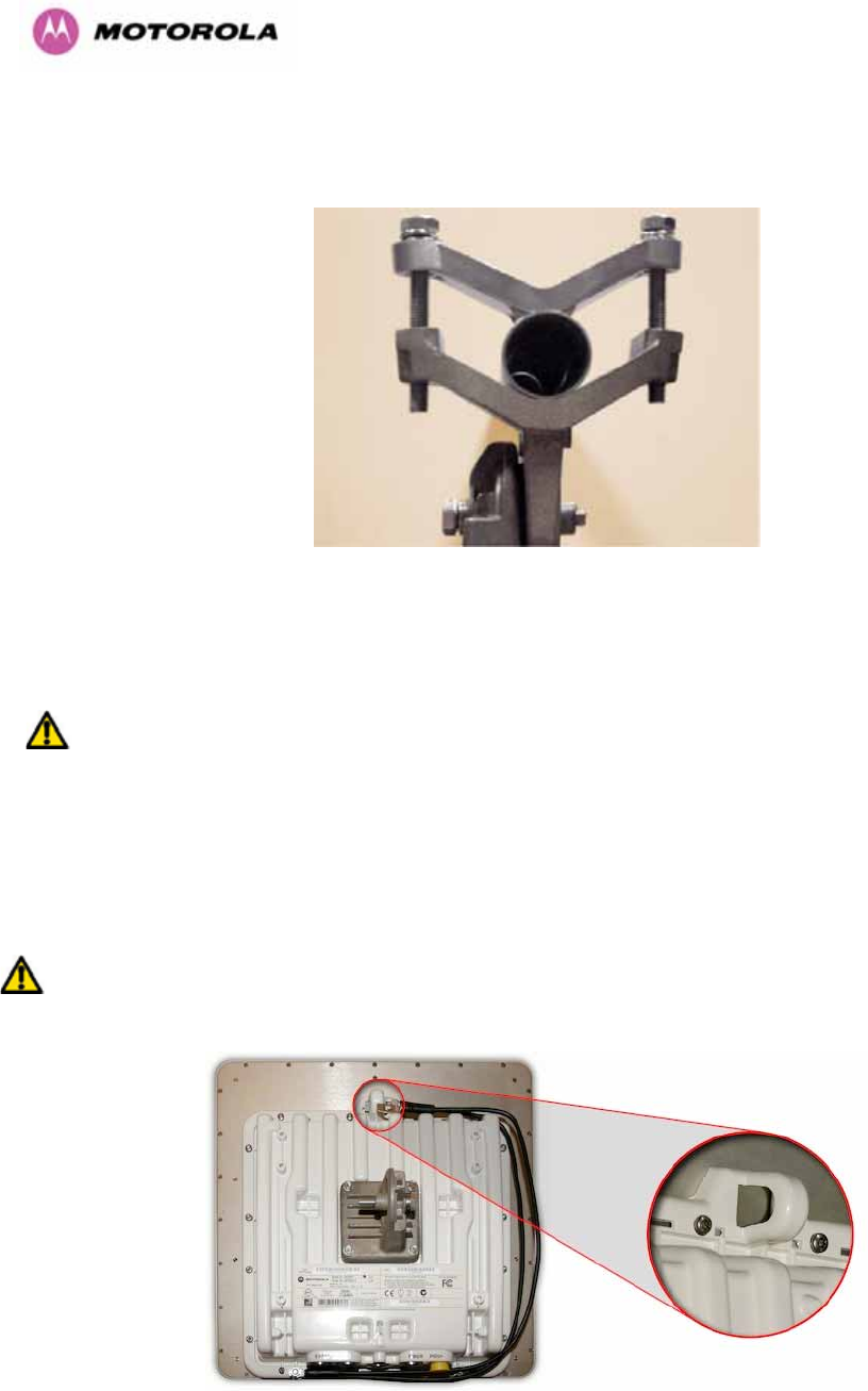
71
Pole diameters of 25mm (1”) to 50mm (2”) can be accommodated by inverting the back of the
bracket as shown in Figure 25.
Figure 25 - Mounting to pole diameters 25mm (1”) to 50mm (2”)
When adjustment is complete tighten all bolts to 14Nm (11lb ft).
Warning: Do not over tighten the bolts as bracket failure may occur.
The enclosure and mounting brackets of the PTP 600 Series Bridge product range are
capable of withstanding wind speeds up to 151mph (242kph). The installer should ensure that
the structure the bridge is fixed to is also capable of withstanding the prevalent wind speeds
and loads. See Section 11 “Wind Loading”.
The integral safety loop should be used both for hoisting the ODU up a mast or building and
into position, and also as a fixing point to secure a permanent safety lanyard from the
tower/building to the ODU in case of mounting failure.
Figure 26 - Integral Safety Loop
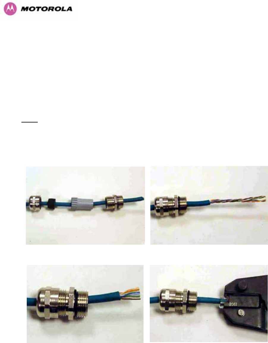
72
The length of the safety lanyard must not exceed 1m (approx 3 ft) in length. The lanyard
should be made from a material that does not degrade in an outdoor environment.
The safety lanyard must be fixed to a separate fixing point that is not part of the direct
mounting system for the ODU.
7.7 Connecting Up
7.7.1 Preparing the PIDU Plus To ODU Cable
NOTE: The maximum cable length between the ODU and the user’s Network Equipment is
100m (330 ft). Cable lengths up to 300m (984 ft) can be used where the PIDU Plus to ODU
cable is supplying power only, i.e., when using the PTP 600 Series Bridge Optical Interface.
The cable should be assembled to the following instructions:
Step 1: Assemble gland on cable as shown Step 2: Strip the outer insulation
Step 3: Arrange conductors as shown in
Figure 19 and cut to length
Step 4: Insert conductors and crimp
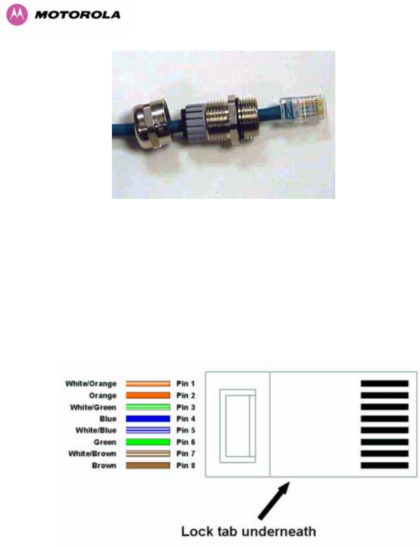
73
Figure 27 - Completed ODU connector
Both ends of the ODU cable are terminated in the same way. The above procedure should be
repeated for the PIDU Plus end of the cable when the cable routing process is complete.
NOTE: The PIDU Plus end of the cable does not employ a cable gland.
Figure 28 - RJ45 Pin Connection (T568B Color Coding)
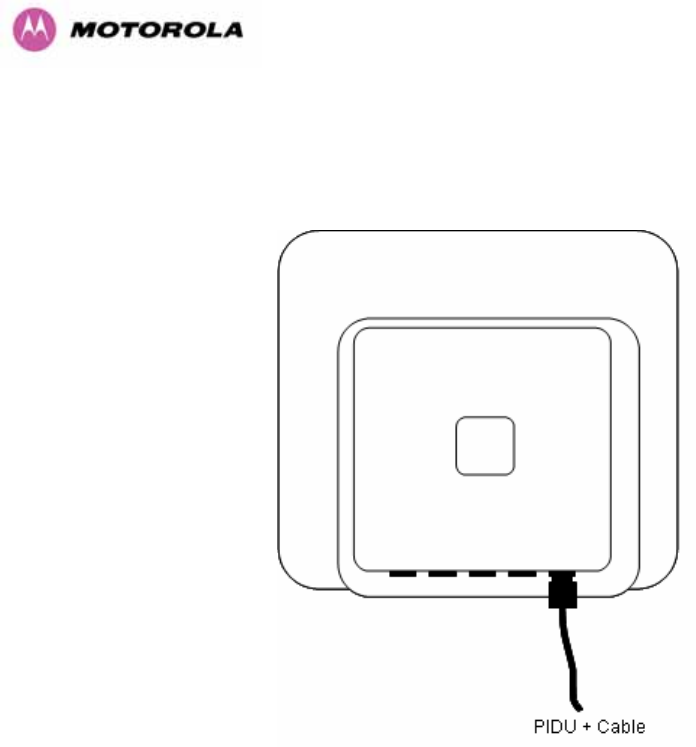
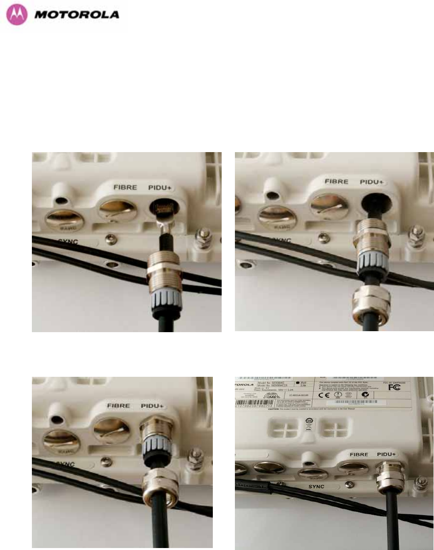
75
7.7.3 Making the PTP 600 Series Bridge PIDU Plus Connection At The ODU
The following procedure describes how connection is made at the ODU. It is often easier to
carry out this procedure on the ground or a suitable surface prior to mounting the ODU.
Ensure that no power is connected to the PIDU Plus or present on the cable before
connecting the ODU.
Step 1: Assemble the cable as described in
5.7.1 above
Step 2: Insert the RJ45 connector making
sure that the locking tab snaps home
Step 3: Screw in the body of the weather
proofing gland and tighten
Step 4: Screw on the clamping nut and tighten

76
Should it be necessary to disconnect the PIDU Plus to ODU cable at the ODU, this can be
achieved by removing the weather proofing gland and depressing the RJ45 locking tab with a
small screwdriver as shown below:
Figure 30 - Disconnecting the ODU
Warning: Ensure that power is removed from the system at the PIDU Plus to prevent damage
to the ODU while making or breaking the connection.
7.7.4 Routing the Cable
After connecting the cable to the ODU it can be routed and secured using standard cable
routing and securing techniques. When the cable is in place it can then be cut to the desired
length at the PIDU Plus prior to connection to the PIDU Plus
7.7.5 Fitting A Surge Arrestor
If you have opted to fit a Surge Arrestor, this should be installed by following the
manufacturer’s instruction. For recommended types see Section 11 “Lightning Protection”
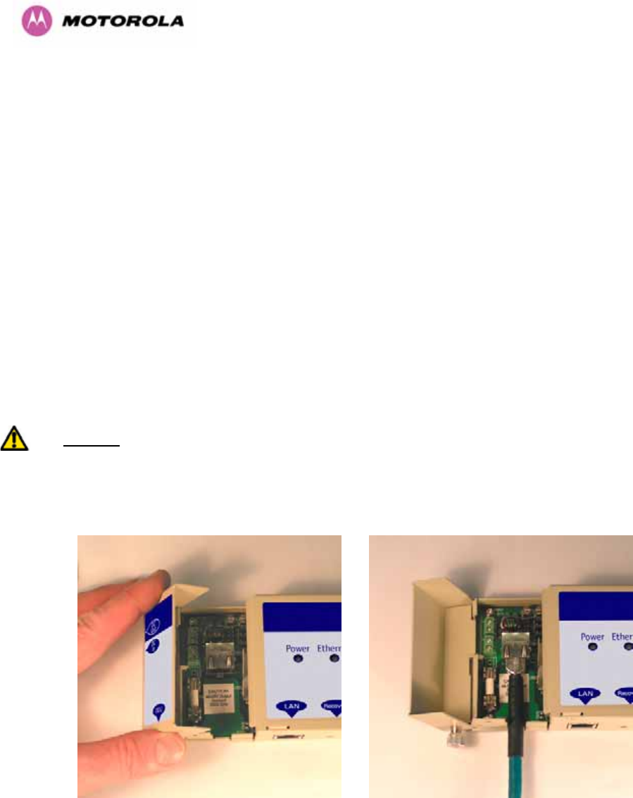
77
7.7.6 Grounding the Installation
The Outdoor Unit (ODU) must be properly grounded to protect against power surges. It is the
user’s responsibility to install the equipment in accordance with Section 810 of the National
Electric Code, ANSI/NFPA No.70-1984 or Section 54 of the Canadian Electrical Code or the
National Electrical Code in the country of installation. These codes describe correct
installation procedures for grounding the outdoor unit, mast, lead-in wire and discharge unit,
size of grounding conductors and connection requirements for grounding electrodes. It is
recommended that installation of the outdoor unit be contracted to a professional installer.
See Section 11 “Lightning Protection” for recommended grounding kits”.
7.7.7 Making the ODU Connection at the PTP 600 Series Bridge PIDU Plus
The ODU is connected to the PIDU Plus by means of a concealed RJ45 connector. The RJ45
connection has been placed inside the PIDU Plus hinged cover to prevent the user from
inadvertently plugging other equipment into the ODU RJ45 socket.
Warning: Plugging other equipment into the ODU RJ45 socket may damage the equipment
due to the non-standard techniques employed to inject DC power into the 1000BaseT
connection between the PIDU Plus and the ODU. Plugging the ODU into other equipment
may damage the ODU and/or the other equipment.
Step 1: Undo the retaining screw and hinge
back the cover.
Step 2: Plug in the ODU into the PIDU Plus
Cable ensuring that it snaps home
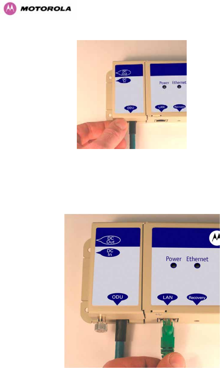
78
Step 3: Replace the cover and secure with the retaining screw
7.7.8 Making the Network Connection at The PIDU Plus – PTP 600 Series Bridge
The Network connection is made by connecting the user’s Network Equipment directly to the
PIDU Plus LAN port as shown in Figure 31.
Figure 31 - Making the Network Connection at the PIDU Plus
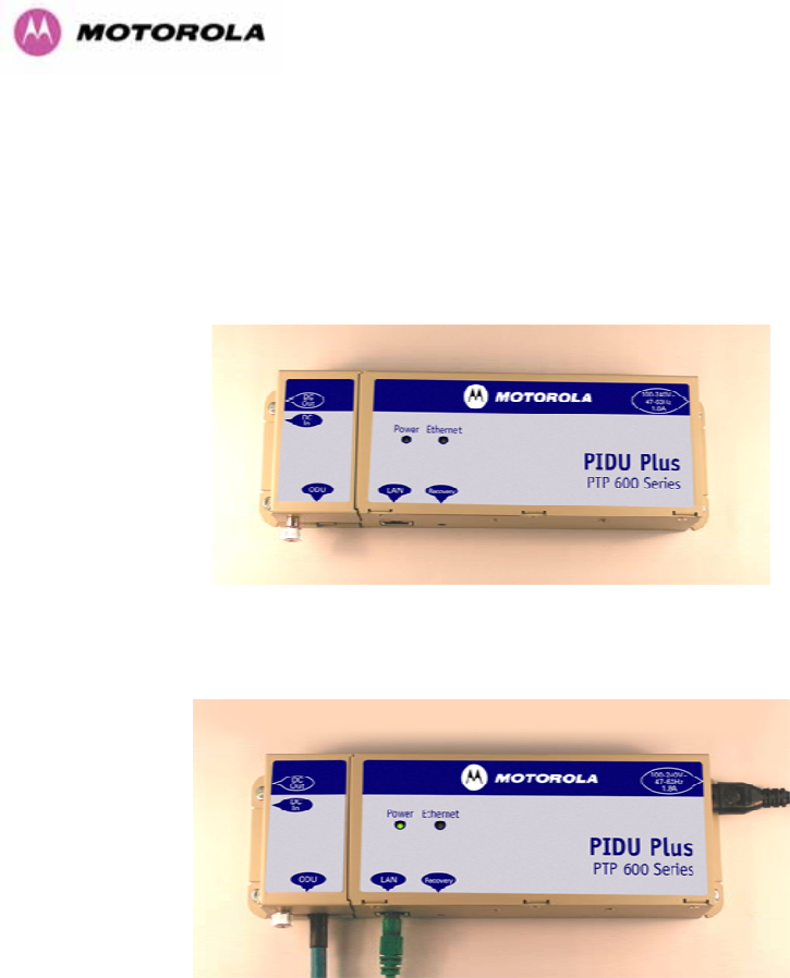
79
7.7.9 Mounting the PTP 600 Series Bridge PIDU Plus
This step is optional. Motorola recommends that you mount the PIDU Plus on a wall or other
suitable mounting surface. This prevents the unit from being knocked or kicked and can help
maintain link availability. Ensure that the reset switch can be accessed when mounting the
unit.
Step 1: Fix the PIDU Plus to the wall using the lugs provided.
Step 2: Make connections as per Section 5.7.7
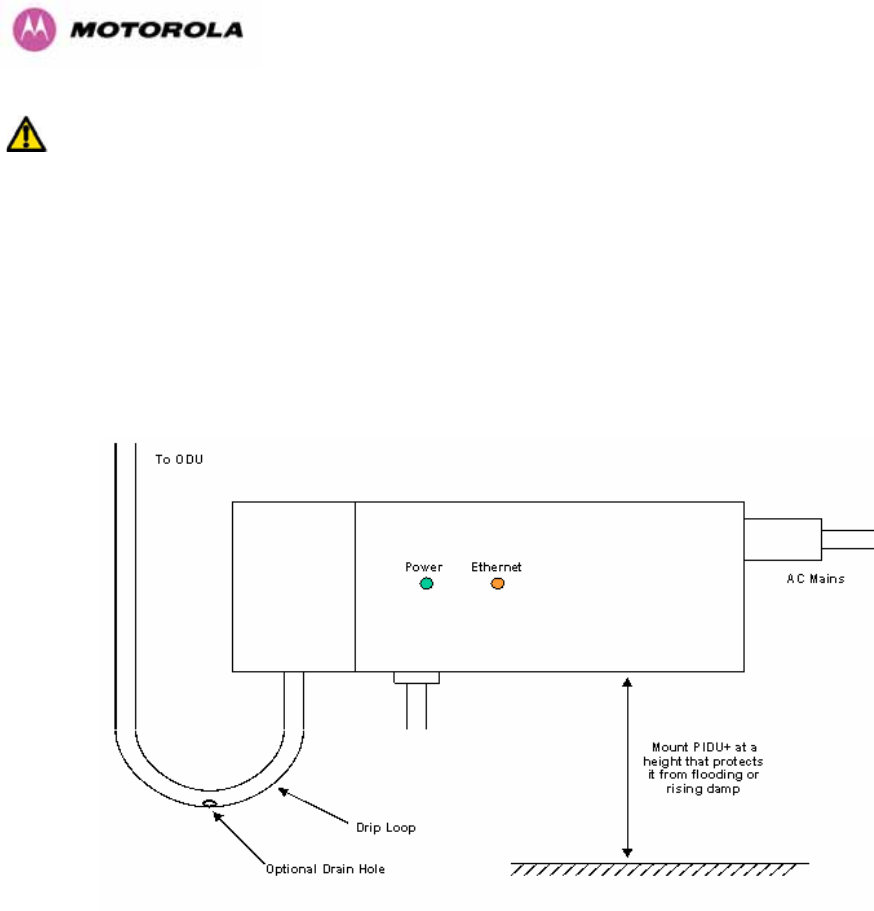
80
WARNING: The PIDU Plus is not waterproof and should be mounted away from sources of
moisture. If mounted outdoors, the unit should be mounted in a rain proof enclosure,
preferably ventilated.
It is also recommended that you fit a drip loop on the PIDU Plus to ODU cable to ensure that
any moisture that runs down the cable into the cabinet or enclosure cannot enter the PIDU
Plus. As shown in Figure 32. The network connection and mains cable should be treated in
the same way if there is a risk that they can carry moisture to the PIDU Plus.
Figure 32 – PTP 600 Series PIDU Plus Drip Loop Configuration

81
WARNING: It is possible for moisture to enter the cable due to damage to the outer protective
layer. This moisture can track down the inside of the cable, filling up the drip loop and
eventually finding its way into the PIDU Plus. To protect against this the outer protective layer
of the cable can be opened up at the bottom of the drip loop to allow this moisture to escape.
WARNING: Some network operators employ gel filled cables to get around the problem of
moisture ingress and transmission. The PTP 600 Series Bridge has NOT been tested against
these cables. Use of gel filled cables may affect the performance of PTP 600 Series bridge.
7.7.10 Powering Up
The PTP 600 Series Bridge is supplied as a pair of matched Master/Slave units. The Master
unit can now be powered up and accessed using the default URL http://169.254.1.2/; the
Slave unit can be accessed using http://169.254.1.1/.
Prior to powering up the PTP 600 Series Bridge, a computer with web browsing capabilities
should be configured with an IP address of 169.254.n.n and subnet mask of 255.255.0.0
where n is any value between 1 and 254 but excluding 1.1 or 1.2. If the default addresses of
the unit 169.254.1.1/2 clashes with an address you are already using on your LAN, or you are
not sure, you should set up an isolated LAN. As the LAN connection presented at the PIDU
Plus has a default configuration as a hub/switch (and auto-sensing MDI/MDIX cross over is
employed), connection can be made directly to the computer using a standard CAT 5 patch
cable.
Before physical installation takes place the units to be installed should be set up as described
in the Section 8.3.4. This process will give the installer the opportunity to set the unit’s IP
address to one that is in the desired address range and set each unit up with the MAC
address of its peer unit ready to establish a radio link. It is recommended that this procedure
be carried out on the bench before physical installation commences. Providing it is safe to do
so, the installer should take the process to the point where a radio link is established before
proceeding to the installation site.
NOTE: It is possible that some units may not be accessed using the above default URL. This
is because these units may have been previously configured with IP addresses 10.10.10.11
(Master) and 10.10.10.10 (Slave). Therefore, users must use the URL http://10.10.10.10/
and/or URL http://10.10.10.11/ to configure the units. Please ensure that a computer with web
browsing capabilities is configured with an IP address of 10.10.10.n, where n is any value
between 2 and 254 but excluding 10 and 11, to configure these units.

82
7.7.11 Aligning the PTP 600 Series Bridge ODUs
The following is a description of the steps taken to establish a radio link between the two
units forming the bridge and align the units for the best signal strength.
The PTP 600 Series Bridge uses audible tones during installation to assist the installer with
alignment. The installer should adjust the alignment of the ODU in both azimuth and elevation
until highest pitch tone is achieved12. The tones and their meanings are as follows:
State Name Tone
Description State Description Pitch Indication (Higher
pitch = higher power)
Free Channel
Search Regular beep Executing band scan N/A
Scanning Slow broken
tone Not demodulating the wanted
signal Rx Power
Synchronized Fast broken
tone Demodulating the wanted
signal Rx Power
Registered Solid tone Both Master and Slave units
exchanging Radio layer MAC
management messages
Rx Power
Table 16 - Audio indications from the ODU
The term ‘wanted signal’ refers to that of the peer unit being installed.
In each of the states detailed above, the unit should be aligned to give the highest pitch tone.
It should be noted that if, when in the Synchronized or Registered state, the tone varies
wildly, you may be suffering from interference or a fast fading link. Installing in this situation
may not give a reliable link. The cause of the problem should be investigated.
For the ease of alignment, both Master and Slave units use the install tones in the same way
but with some small behavioral differences. This allows the installer to install the Slave unit
first and carry out the initial alignment with the Master unit if desired. However, due to the
behavioral differences of Master and Slave units, it is recommended that the Master unit is
installed first and the initial alignment carried out at the Slave unit.
12 The pitch of the alignment tone is proportional to the received power of the wireless signals. The
best results are usually achieved by making small incremental movement in angular alignment.

83
The following behavior should be noted:
• When first started up and from time to time, the Master unit will carry out a band scan to
determine which channels are not in use. During this time, between 10 and 15 seconds,
the Master unit will not transmit and as a consequence of this neither will the Slave unit.
During this time the installation tone on the master unit will drop back to the band scan
state, and the Slave unit will drop back to the Scanning state with the pitch of the tone set
to the background noise level. Alignment of the unit should cease during this time.
• The master unit can take up to 60 seconds in 0-40km (0-25 miles) mode, 90 seconds in
0-130km (0-81 miles) mode and 120 seconds in 0-200km (0-124 miles) mode to
determine the range of the link being installed13. The Master unit will remain in the
Scanning state until the range of the link has been established. The Master unit will only
move to the Synchronized state when the range of the link has been established.
• If, at the end of the ranging period, the Registered state is not achieved due to
interference or other reasons, the Master unit will retry twice more on the same channel
before moving to another available channel. Should this occur it might take a number of
minutes to establish a link in the Registered state.
• The Slave unit does not have a ranging process. The slave unit will change to the
Synchronized state as soon as the wanted signal is demodulated.
When the alignment process is complete the installer MUST REMEMBER TO DISARM BOTH
UNITS in the link as described in Section 8.3.4. This is necessary in order to:
• Turn off the audible alignment aid
• Enable Adaptive Modulation
• Fully enable Advanced Spectrum Management with i-DFS
• Clear unwanted installation information from the various systems statistics
• Store the link range for fast link acquisition on link drop
• Enable higher data rates
13 If the unit is operating where mandatory radar avoidance algorithms are implemented the ranging
behaviour for the PTP 600 Series Bridge may be affected. The Master has to monitor the initially
chosen channel for 60 seconds to make sure it is clear of radar signals before transmitting. If a radar
is detected during any of the installation phases a further compulsory 60 seconds channel scan will
take place as the master unit attempts to locate a new channel that is free of radar interference

84
8 Web Page Reference
The web user interface has three main sections. The home page presents to the operator a
high level summary of the PTP 600 Series Bridge point-to-point wireless link. The status page
presents a more detailed set of system parameters describing the performance of the
wireless link together with other key system performance metrics. The final section is the
system administration section. This section is password protected and allows the system
administrator to perform all the day-to-day administrative procedures, e.g. software upgrade
and performing configuration changes.
The following subsections give a detailed usage guide for all the web user interfaces.
The web pages are best viewed using a screen resolution of at least 1024 x 768 pixels on a
PC using Microsoft Internet Explorer Version 614.
14 The web pages have also been tested with Firefox 1.0.6. Other browsers may function correctly but
have not been tested.
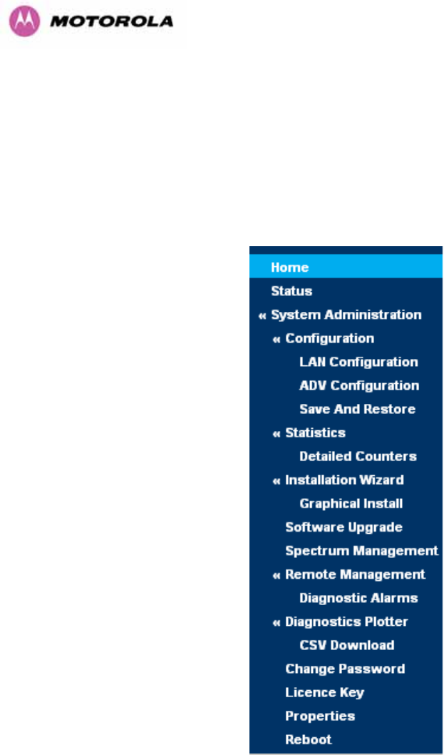
85
The navigation bar on the left hand side of the web page is used to move between the various
management pages. The currently selected page is always highlighted with a dark blue
background. The menu is hierarchical. Selecting a menu item which has associated submenu
options will automatically display all sub options. A sample web page with the navigation
menu is shown in Figure 33 when the ‘Home’ Link is highlighted as the current page.
Figure 33 - Menu Navigation Bar
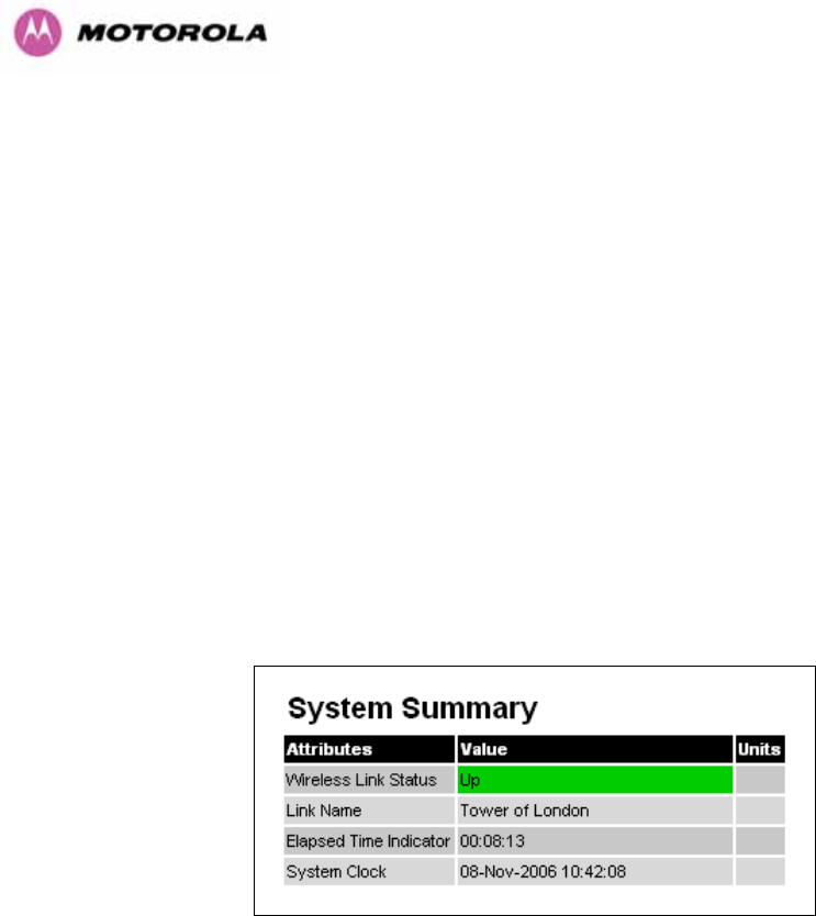
86
8.1 Home Page – PTP 600 Series Bridge
The home page for the PTP 600 Series Bridge has been designed to display a high level
summary of the status of the wireless link and associated equipment. The home page (Figure
34) normally displays four key system attributes:
Wireless Link Status: The Wireless Link Status attribute displays the current status of the
PTP 600 Series Bridge wireless link. A state of ‘Up’ on a green background indicates that a
point-to-point link is established. A state of ‘Down’ on a red background indicates that the
wireless link is not established. If the link is down for an unknown reason the system
administrator should first consult the status web page for a more detailed summary of up to
date system diagnostics.
Link Name: The link name attribute is a name and/or handle allocated by the system
administrator to aid the identification of the unit, network or building.
Figure 34 - System Summary Page
Elapsed Time Indicator: The elapsed time indicator attribute presents the total time in days,
hours, minutes and seconds since the last system restart. The system can restart for several
reasons, e.g., commanded reboot from the system reboot webpage, or a power cycle of the
equipment.
System Clock: If SNTP (Simple Network Time Protocol) is enabled, or the clock has been
set, then a system clock attribute is displayed giving the date and time of the last page
refresh. Section 8.3.11.6 explains how to enable SNTP and Section 8.3.11.7 explains how to
set the clock.
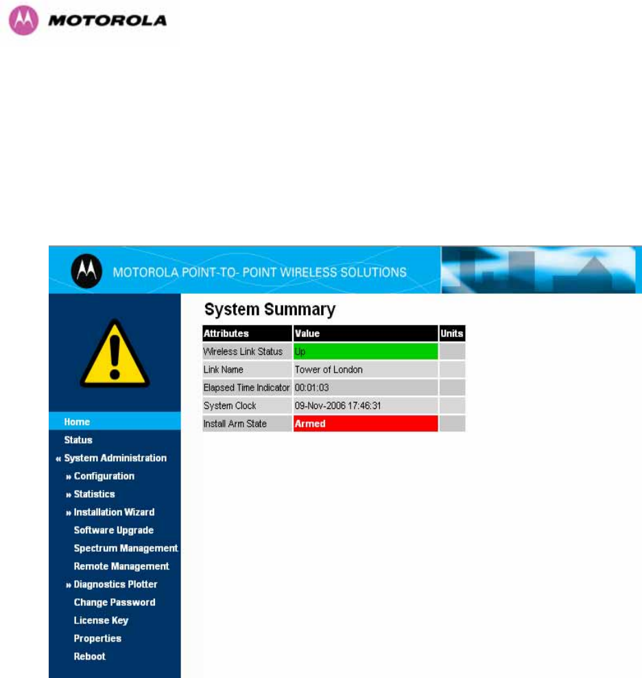
87
8.1.1 Home Page Alarm Display
The home page is also used to display all outstanding major system alarms. Whenever
system alarms are asserted, a yellow warning triangle is displayed on web page navigation
bar. The warning triangle will be visible from all web pages. Clicking the warning triangle will
cause the web page to jump back to the system homepage. Figure 35 shows a sample alarm
screen.
Figure 35 - Alarm Warning Triangle

88
The following system alarms are defined:
Ethernet Link Status: Current status of the Ethernet link. If there are any problems with the
Ethernet interface, this alarm will be asserted. This alarm will most likely be seen if the unit
has no Ethernet cable plugged into its Ethernet socket. Note that a change of state may
generate an SNMP trap and/or SMTP email alert.
Telecoms Channel A Status: Current status of telecoms channel A. Indicates that there is a
problem with the telecoms channel A. Possible problems are "No Signal (local)", "No Signal
(Remote)", and "No Signal (Local and Remote)". Note that a change of state may generate an
SNMP trap and/or SMTP email alert.
Telecoms Channel B Status: Current status of telecoms channel B. Indicates that there is a
problem with the telecoms channel B. Possible problems are "No Signal (local)", "No Signal
(Remote)", and "No Signal (Local and Remote)". Note that a change of state may generate an
SNMP trap and/or SMTP email alert.
Telecoms Interface A Loopback: The loopback status of telecoms channel A. This is
intended for installation testing and should be set to 'None' for normal operation. The wire
connections to a unit can be tested by applying a 'Copper' loopback to the local unit. The
wireless connection to the remote unit can be tested by applying a 'Wireless' loopback to the
remote unit with no loopback on the local unit. Note that a change of state may generate an
SNMP trap and/or SMTP email alert. The loopback can be disabled from the telecoms
configuration sub menu (see Section 8.3.1.6).
Telecoms Interface B Loopback: The loopback status of telecoms channel B. This is
intended for installation testing and should be set to 'None' for normal operation. The wire
connections to a unit can be tested by applying a 'Copper' loopback to the local unit. The
wireless connection to the remote unit can be tested by applying a 'Wireless' loopback to the
remote unit with no loopback on the local unit. Note that a change of state may generate an
SNMP trap and/or SMTP email alert. The loopback can be disabled from the telecoms
configuration sub menu (see Section 8.3.1.6).

89
Region Code: The region code prohibits the wireless unit from operating outside the
regulated limits. An invalid region code indicates a corrupted license key. Note that a change
of state may generate an SNMP trap and/or SMTP email alert.
Install Status: A non-zero value indicates that signaling was received with the wrong MAC
address. Note that it is very unusual to detect this, because units with mis-configured Target
MAC Address will normally fail to establish a wireless link. However, rare circumstances may
establish a partial wireless link and detect this situation. NB: A non-zero value on start-up, or
a change of value during operation, may generate an SNMP trap and/or SMTP email alert.
Install Arm State: This alarm warns when a wireless unit is in installation mode. After
installation the wireless unit should be disarmed. This will increase the wireless link’s data-
carrying capacity and stop the installation tone generator. The wireless link is disarmed from
the ‘Installation Wizard’ see Section 8.3.4. Note that a change of state may generate an
SNMP trap and/or SMTP email alert.
Unit Out Of Calibration: The unit is out of calibration.
Encryption Enable Mismatch: Encryption has been enabled on one end of the wireless link
but not the other.
Incompatible Region Codes: The PTP 600 Series Bridge uses region codes to comply with
local regulatory requirements governing the transmission of wireless signals in the 5.8, 5.4
GHz and 2.5GHz bands. Region codes can only be changed by obtaining a new PTP 600
Series license key. If this alarm is encountered the appropriate license keys from the country
of operation should be obtained from your distributor. Applying license keys containing the
same region codes to both ends of the link will remove the alarm.
No Wireless Channel Available: Spectrum Management was unable to locate a suitable
wireless channel to operate on.
Wireless Link Disable Warning: This warning is displayed if the Wireless link has been
administratively disabled via the SNMP Interface. The Wireless Interface MIB-II ifAdminStatus
attribute has been set to DOWN. To enable the Ethernet interface, set the ifAdminStatus
attribute to UP.
Ethernet Link Disable Warning: This warning is displayed if the Ethernet link has been
administratively disabled via the SNMP Interface. The Ethernet Interface MIB-II ifAdminStatus

90
attribute has been set to DOWN. To enable the Ethernet interface, set the ifAdminStatus
attribute to UP.
Fiber Link Status: If the fiber link is not OK, there are two possible causes: Either the fiber
link has been installed but disabled (because the license key does not include fiber support),
or the link could not be established even though an optical carrier was detected (due perhaps
to a broken TX fiber, or the link is disabled at the fiber link partner). Note that a change of
status may generate an SNMP trap and/or SMTP email alert.
Ethernet Configuration Mismatch Alarm: The detection of Ethernet fragments (runt
packets) when the link is in full duplex is an indication of an auto-negotiation or forced
configuration mismatch.
Incompatible Master and Slave: A non-zero value indicates that the master and slave ends
of the wireless link are different hardware products, or have different software versions. Note
that it is very unusual to detect this because incompatible units will normally fail to establish a
wireless link. However, some combinations may establish a partial wireless link and detect
this situation. Note that a non-zero value may generate an SNMP trap and/or SMTP email
alert.
TDD Synchronization Status: Current status of the TDD Synchronization (acquiring
synchronization, no timing reference and timing system not connected).
SNTP No Sync Warning: This warning indicates that SNTP has been enabled but that the
unit is unable to synchronize with the specified SNTP server. Section 6.3.9.5 explains how to
configure SNTP.
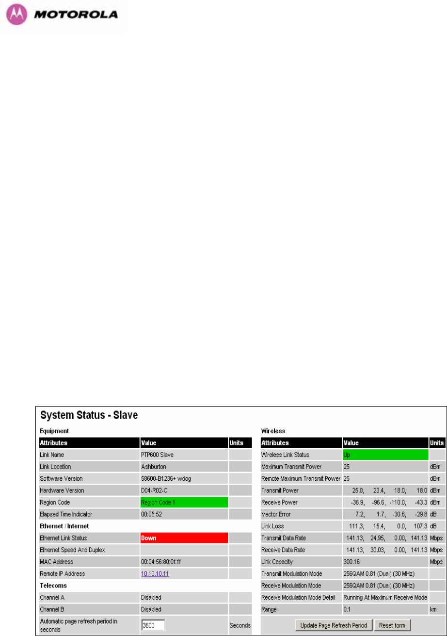
91
8.2 Systems Status Page
The status page has been designed to give the system administrator a detailed view of the
operation of the 600 Series Bridge from both the wireless and network perspectives.
The page is subdivided into three main categories Equipment, Wireless, Telecoms and
Ethernet/Internet. The ‘Equipment’ section contains the unit’s inventory and identification
information. The ‘Wireless’ section presents the key wireless metrics, which are displayed as
a series of measurements and histograms. The ‘Ethernet/Internet’ section describes the unit’s
network identity and connectivity. “Telecoms” controls the unit’s E1/T1 telecoms interfaces.
The status page can be configured to refresh itself at an operator defined rate (if the user is
logged in as system administrator). The refresh period defaults to 3600 seconds and can
easily be changed to refresh at any period between 3 seconds and 3600 seconds. Pressing
the ‘Update Page Refresh Period’ button causes a new page refresh period to be adopted by
the system. The page refresh mechanism uses a HTML Meta refresh command. Therefore
the refresh is always initiated by the local browser and not by the 600 Series Bridge at this
interval.
The two PTP 600 Series bridges units are arranged in a master and slave relationship. The
roles of the units in this relationship are displayed in the page title. The master unit will always
have the title ‘- Master’, and the slave will always have ‘- Slave’ appended to the ‘Systems
Status’ page title.
Figure 36 - Status Page

92
The following section details all the attributes displayed on the status page:
Link Name: The link name is allocated by the system administrator and is used to identify the
equipment on the network. The link name attribute is limited to a maximum size of 63 ASCII
characters.
Link Location: The link location is allocated by the system administrator and can be used as
a generic scratch pad to describe the location of the equipment or any other equipment
related notes. The link location attribute is limited to a maximum size of 63 ASCII characters.
Software Version: The attribute describes the version of software installed on the
equipment. The format of the attributes is FFSSS-XX-YY where FF is the frequency variant
(2.5, 5.4 or 5.8GHz), SSS is the System Release, XX is the major release version and YY is
the minor release version.
Hardware Version: The hardware version attribute contains all the combined hardware
version information. The attribute is formatted as DXX-RYY-Z where DXX contain the version
of the digital card, RYY contains the version of the RF (radio frequency) card and Z describes
the antenna type which can be I (integrated) or C (connectorized).
Region Code: The region code is used by the system to constrain the wireless to operate
within regulatory regime of the particular country. The region code is encoded in the product
license key. If the operator wishes to change region code, a new license key must be
obtained from Motorola or the local point-to-point distributor / system integrator.
Elapsed Time Indicator: The elapsed time indicator attribute presents the total time in years,
days, hours, minutes and seconds since the last system restart. The system can restart for
several reasons, e.g. commanded reboot from the system reboot web page, or a power cycle
of the equipment.
Ethernet Link Status: Current status of the Ethernet link. A state of ‘Up’ with a green
background indicates that an Ethernet link is established. A state of ‘Down’ with a red
background indicates that the Ethernet link is not established.

93
Ethernet Speed and Duplex: The negotiated speed and duplex setting of the Ethernet
interface. The speed setting is specified in Mbps. Full Duplex data transmission means that
data can be transmitted in both directions on a signal carrier at the same time. For example,
on a local area network with a technology that has full duplex transmission; one workstation
can be sending data on the line while another workstation is receiving data. Half Duplex data
transmission means that data can be transmitted in both directions on a signal carrier, but not
at the same time. For example, on a local area network using a technology that has half
duplex transmission, one workstation can send data on the line and then immediately receive
data on the line from the same direction in which data was just transmitted.
Remote IP Address: Hyperlink to the other side of the Link. The IP address of the pier link is
displayed if the Link is UP, otherwise “unavailable” is displayed.
Channel A: The status of telecom interface A.
Channel B: The status of telecom interface B.
Wireless Link Status: As the attribute name suggests it displays the current status of the
wireless link. A state of ‘Up’ on a green background indicates that a point-to-point link is
established. A state of ‘Down’ on a red background indicates that the wireless link is not
established.
Maximum Transmit Power: The maximum transmit power that the local wireless unit is
permitted to use to sustain a link.
Remote Maximum Transmit Power: The maximum transmit power that the remote wireless
unit is permitted to use to sustain a link.
Transmit Power: Transmit power histogram15 is expressed in dBm and presented as: max,
mean, min, and latest. The max, min and latest are true instantaneous measurements; the
mean is the mean of a set of one second means.
Receive Power: Receive power histogram is expressed in dBm and presented as: max,
mean, min, and latest. The max, min and latest are true instantaneous measurements; the
mean is the mean of a set of one second means. See note 15.
15 All histograms are calculated over a one hour period. If the equipment has been running for less
than one hour then the histograms are calculated over the current elapsed time.
The data used to compute the histogram statistics can be downloaded in an ASCII comma separated
value (CSV) format via the diagnostics CSV Download page, see Section 8.3.12.2.

94
Vector Error: The vector error measurement compares the received signal’s In phase /
Quadrature (IQ) modulation characteristics to an ideal signal to determine the composite error
vector magnitude. The results are stored in a histogram and expressed in dB and presented
as: max, mean, min and latest. The max, min and latest are true instantaneous
measurements; the mean is the mean of a set of one second means. The expected range for
Vector Error would be approximately -2dB (NLOS link operating at sensitivity limit on BPSK
0.67) to –33dB (short LOS link running 256 QAM 0.83). See note 15.
Link Loss: The link loss is the total attenuation of the wireless signal between the two
point-to-point units. See note 15.
The link loss calculation presented below:
xxxx RTRTll ggPPP
+
+
−
=
Where
ll
P Link Loss (dB)
x
T
P
Transmit power of the remote
wireless unit (dBm)
x
R
P
Received signal power at the local
unit (dBm)
xx RT gg ,
Antenna gain at the remote and local
units respectively (dBi). The antenna
gain of the 600 Series bridge (23.5
dBi) is used unless one or both of
the Gemini units is a Connectorized
version. See Section 11.3 for more
details
Equation 2 - Link Loss

95
Transmit Data Rate: The data rate in the transmit direction, expressed in Mbps and
presented as: max, mean, min, and latest histogram format. The max, min and latest are true
instantaneous measurements; the mean is the mean of a set of one second means.
See note 15. Expected data rates can be found in Section 4.1.4 “Aggregate Ethernet
throughput rate v maximum link loss”.
Receive Data Rate: The data rate in the receive direction, expressed in Mbps and presented
as: max, mean, min, and latest histogram format. The max, min and latest are true
instantaneous measurements; the mean is the mean of a set of one second means.
See note 15. Expected data rates can be found in Section 6.1.5.
Link Capacity: The maximum aggregate data rate capacity available for user traffic,
assuming the units have been connected using Gigabit Ethernet. The link capacity is variable
and depends of the prevailing wireless conditions as well as the distance (range) between the
two wireless units. When the link is idle and in ‘IP Mode’ the wireless link will adaptively
configure itself into a lower latency mode, this will cause the displayed link capacity and
aggregate data rates to diverge. This is because the aggregate data rate displays the
instantaneous capacity of the wireless link not the maximum potential capacity of the link as
displayed by link capacity.
Transmit Modulation Mode: The modulation mode currently being used on the transmit
channel. Details on the modulation modes can be found in Section 23.1 “System
Specifications”.
Receive Modulation Mode: The modulation mode currently being used on the receive
channel. Details on the modulation modes can be found in Section 23.1 “System
Specifications”.
Receive Modulation Mode Detail: This supplies the user with information regarding the
receive modulation mode in use. Possible values are:
• Running at maximum receive mode
• Running at user-configured Max Modulation Mode
• Restricted due to byte errors on the wireless link or local Ethernet Tx Fifo Drops
• Restricted because a DFS channel change is in progress
• Restricted due to telecoms acquisition mode
• Restricted due to the low Ethernet link speed
• Limited by the wireless conditions
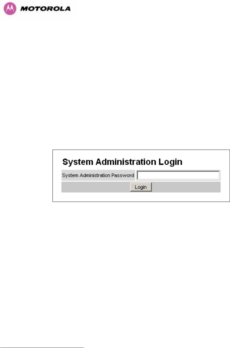
96
Range: The range16 between the 600 Series bridge ODUs.
Refresh Page Period: The Status page refreshes automatically according to the setting
entered here (in seconds). This attribute is only displayed when the user is logged on as
System Administrator.
8.3 System Administration Pages
The following menu options are available for the system administrator and can be password
protected. Figure 37 shows the system administration login page. By default a system
administrator password is not set. Simply click the login button to access the system
administration features.
Figure 37 - System Administration Login Page
Once the password has been set using the ‘Change Password’ menu item the system
administration pages will only be available after the user has entered the correct password.
16 The PTP 600 Series Bridge displays range in km by default, if the user would prefer to display
range using Miles the ‘Distance Units’ attribute should be set to imperial, see the “ ” web
page Section 8.3.15.
Properties

97
The features that are only available to the system administrator are:
• Configuration
• Statistics
• The Installation Wizard
• Software Upgrade
• Spectrum Management including DFS
• Remote management
• Diagnostics Plotter
• Password Management
• License Key Management
• Properties
• System Reboot
8.3.1 System Configuration
The configuration of the 600 Series Bridge is organized into three sections:
• General configuration
• LAN configuration
• Telecoms Configuration
• Save and Restore
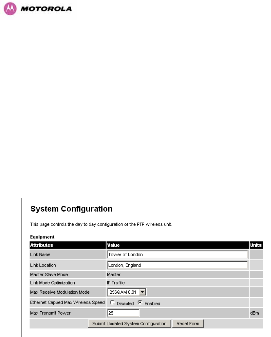
98
The general configuration allows modification of high level administrative (descriptive)
attributes and high level wireless configuration.
The LAN configuration sub menu allows the system administrator to modify the Ethernet and
IP configuration of the 600 Series Bridge.
The telecoms submenu displays the current status of the telecoms interface and allows the
configuration of interface loopbacks.
The save and restore submenu allows the system administrator to backup and restore the
bridge configuration. It is recommended after a unit has been successfully installed; a copy of
the active configuration is taken and archived by the system administrator.
8.3.1.1 General Configuration Page
The general configuration page (Figure 38) is used by the system administrator to configure
the 600 Series Bridge’s high level administrative (descriptive) attributes and high level
wireless configuration.
Figure 38 - System Configuration Page

99
While the majority of the system configuration is entered during installation and should never
require changing, this page offers the system administrator the ability to change the basic
system parameters for both the wireless and Ethernet components.
Link Name: User defined identity for the unit (max 63 characters).
Link Location: Can be used as a generic scratch pad to describe the location of the
equipment.
Max Receive Modulation Mode: This is the maximum mode the unit will use as its adaptive
modulation. The modulation modes available are specified in Section 23.1 ”System
Specifications”.
By default the Max Receive Modulation Mode is the highest mode available.
For minimum error rates on TDM links the user should set the maximum modulation mode to
64QAM 0.75 at both ends of the link.
Ethernet Capped Max Wireless Speed: When enabled this option will cap the wireless
speed to a mode that the connected Ethernet connection can sustain.
Maximum Transmit Power: This specifies the maximum transmit power in dBm of the
system. It is country dependent and although the user can change this in 1dB steps, it will be
limited to that country’s regulations17.
Why Reduce Transmit Power?
If the link losses are low and the link data rate and availability targets are being easily
achieved, the transmitted power level may be reduced with a consequent benefit to other
users of the band, .e.g. fixed satellite links.
17 In the UK there is a legal requirement to provide a minimum of 19dB of transmit power control
range. When the equipment is operating with a UK Licence Key, an additional facility is provided on
the configuration page that allows the transmitted power to be reduced by 19dB compared to the
maximum allowed with a simple single step control.
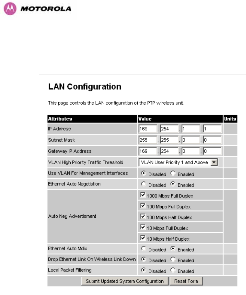
100
8.3.1.2 LAN Configuration Page
The LAN configuration page (Figure 39) is used by the system administrator to configure the
600 Series Bridge’s LAN interface.
Figure 39 - LAN Configuration Page
IP Address: Internet protocol (IP) address. This address is used by the family of Internet
protocols to uniquely identify this unit on a network.
Subnet Mask: A subnet allows the flow of network traffic between hosts to be segregated
based on a network configuration.
Gateway IP Address: The IP address of a computer / router on the current network that acts
as a gateway.

101
VLAN High Priority Traffic Threshold: All packets with an 802.1P priority tag greater than
or equal to the indicated value will be treated as a high priority packet for transmission over
the wireless link.
Use VLAN For Management Interfaces: This controls whether the management interfaces
(WWW/SNMP/SMTP/SNTP) use 802.1Q VLAN tags or not. See Section 8.3.1.3.
Ethernet Auto Negotiation This enables the Ethernet configuration to be forced rather than
auto negotiated.
Warning: The configuration should only be forced if you are having problems with auto
negotiation. You must ensure that you configure both this unit and the Ethernet port to
which it is connected identically. If you force a fixed Ethernet Configuration on the 600
Series bridge then you MUST also force the same fixed configuration on the equipment
to which it is connected. If you fail to force the configuration of the connected
equipment, its automatic configuration mechanisms will normally cause a duplex
mismatch, and you will receive greatly reduced throughput!
When Ethernet Auto Negotiation is Disabled the format of the LAN configuration page will
change see Section 8.3.1.4 “LAN Configuration Page – Manual Ethernet Configuration”.
Auto Neg Advertisement: This controls the rates that the auto negotiation mechanism will
advertise as available. Warning: Over the air throughput will be capped to the rate of the
Ethernet interface at the receiving end of the link.
Ethernet Auto Mdix: This enables/disables the Auto Medium Dependent Interface
(MDI)/Medium Dependent Interface Crossover (MDIX) capability.
Drop Ethernet Link On Wireless Link Down: When this option is enabled the Ethernet link
is momentarily dropped when the wireless link goes down. This feature is used to indicate to
the connected network equipment that this Ethernet link is no longer available, thus causing
STP (Spanning Tree Protocol) to re-route packets through an alternate link.
Local Packet Filtering: When Local Packet Filtering is “Enabled”, the bridge learns the
source MAC addresses of devices transmitting Ethernet packets on the local Ethernet
network, and only bridges packets to the remote unit if the destination MAC address has not
been learned as a 'local' device. When Local Packet Filtering is ‘Disabled’ the bridge does
not learn the source MAC addresses of devices transmitting Ethernet packets on the local
Ethernet network, and bridges ALL Ethernet packets received to the remote unit. Local
Packet Filtering should be disabled when external Ethernet switching hardware or a router is
present. The default setting for Local Packet Filtering is disabled.
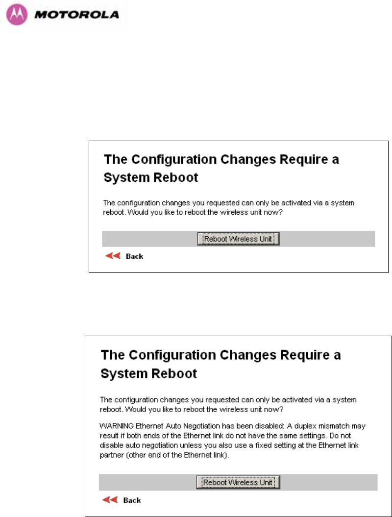
102
All of the above attributes are non-volatile, once set they will be used by the unit even after a
power on reboot. A number of attributes, such as IP Address, Subnet Mask and Gateway IP
Address and VLAN settings will require a reboot before they are used. If any of these
attributes are changed a reboot screen appears asking the user to verify the reboot (Figure
40 or Figure 41).
Figure 40 - Configuration Reboot Page
Figure 41 - Configuration Reboot Page - Ethernet Auto Negotiation Disabled
This will be followed by a pop-up dialogue box asking to confirm the action.
Note: At this point you will lose connection to the unit. If you have just changed the IP
Address you now have to reconnect to the unit using the address just set.
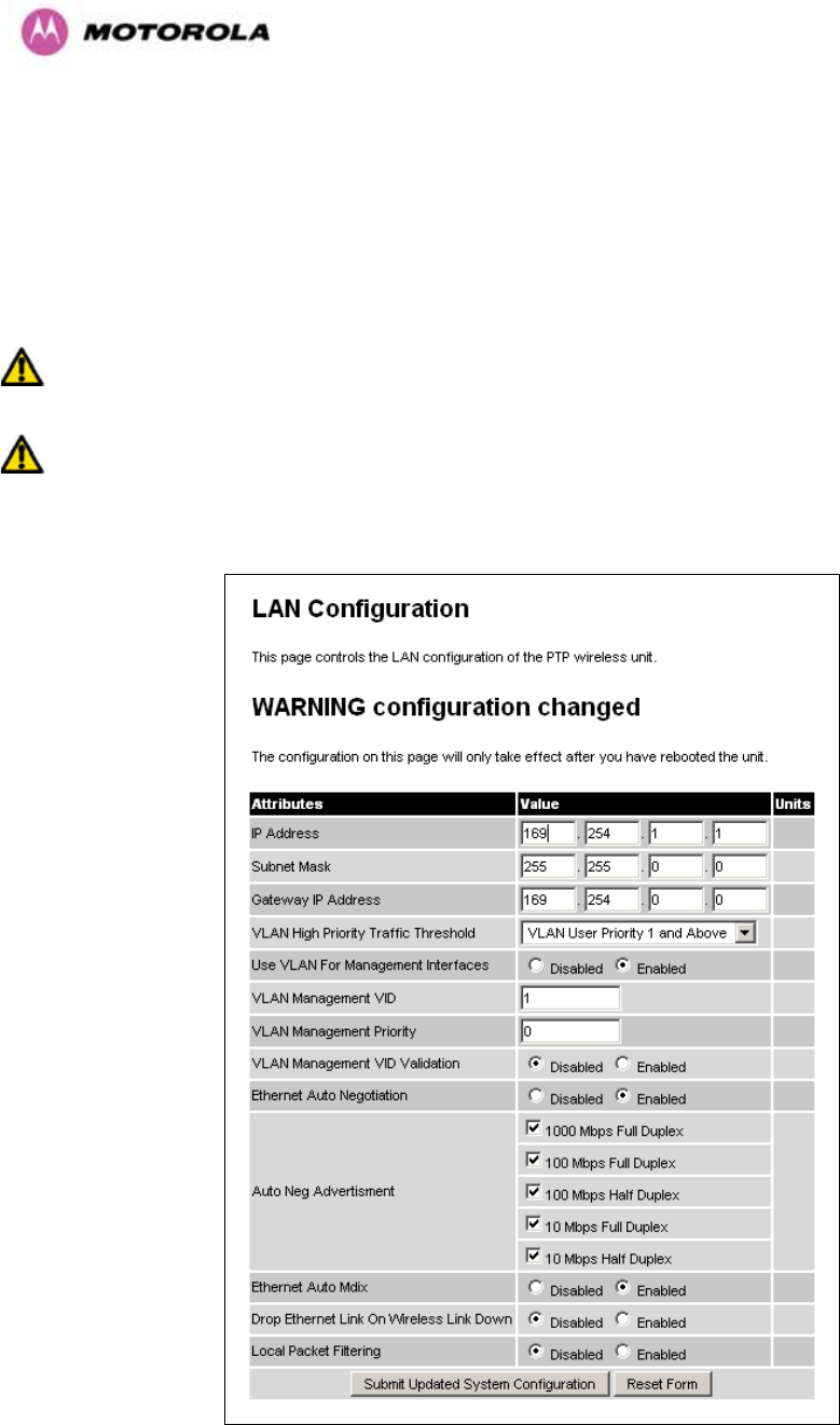
103
8.3.1.3 LAN Configuration Page – Use VLAN For Management Interfaces
The layout of the LAN Configuration page changes if this attribute is enabled in order to allow
the VLAN VID and VLAN Priority to be set, see Figure 42. The VLAN settings are applied only
after the unit is rebooted.
Warning: You must ensure that you can access the VLAN which you configure here,
otherwise you will be unable to access the unit following the next reboot.
Warning The PTP 600 is only compatible with single VLAN tagged packets. Any packet
with two or more packets will be ignored.
Figure 42 - VLAN Configuration Fields
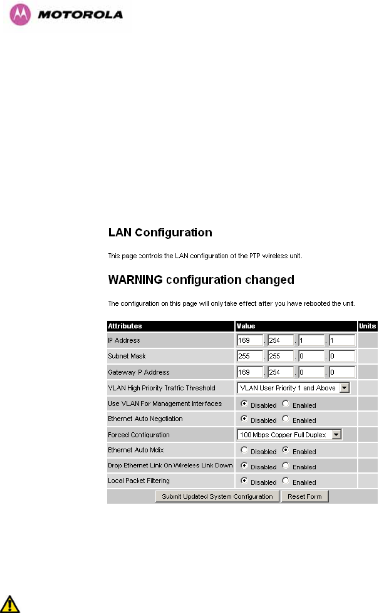
104
VLAN Management VID: This 802.1Q VLAN VID will be included in packets generated by
the management interfaces. Valid settings are in the range 0 to 4094.
VLAN Management Priority: This 802.1Q VLAN Priority will be included in packets
generated by the management interfaces. Valid settings are in the range 0 to 7.
VLAN Management VID Validation: If enabled, the management interfaces will only respond
to Ethernet packets tagged with the configured 802.1Q VLAN Management VID; otherwise
packets with any VID will be accepted.
8.3.1.4 LAN Configuration Page – Manual Ethernet Configuration
Figure 43 - LAN Configuration Page - Manual Ethernet Configuration
Force Configuration: This option allows the user to force the speed and duplex setting of the
Ethernet interface.
Warning: Over the air throughput will be capped to the rate of the Ethernet interface at
the receiving end of the link
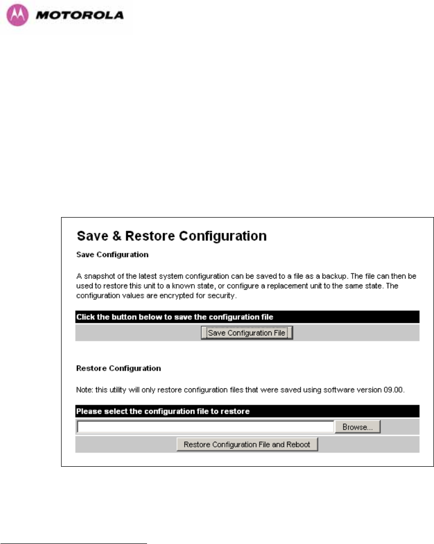
105
8.3.1.5 Save and Restore Configuration File
The save and restore feature of a PTP 600 Series Bridge allows the system administrator to
backup the operation configuration of the wireless unit. It is recommended that this facility is
used immediately after a successful PTP 600 Series Bridge installation or prior to any
software upgrade. In the unlikely event that a unit has to be replaced in the field, the
replacement unit can be reconfigured by simply playing back the saved configuration file.
To save the configuration file click on the ‘Save Configuration File’ button (Figure 44) and
save the configuration file (.cfg) to the hard drive of your computer18 19.
Figure 44 - Save and Restore Configuration Page
18 There is a feature of Internet Explorer (all versions) that will always look at the content of any
downloadable file as make an assessment whether to treat the file as an ASCII or binary file.
Unfortunately the configuration file is always treated as ASCII and the browser attempts to display it
instead of downloading it. Firefox (all versions) makes no such assumptions.
19 The configuration file format is MAC-mm-mm-mm_IP-iii-iii-iii-iii.cfg where mm and iii are the lower 3
bytes of the MAC address and the unit IP address respectively.
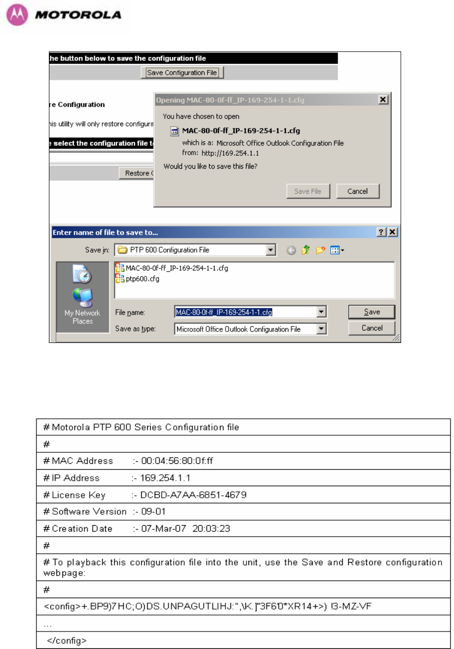
106
Figure 45 - Save Configuration File Screen
The configuration file is encoded using an ASCII encoding scheme. An example is show in
Figure 46.
Figure 46 – PTP 600 Example Configuration File
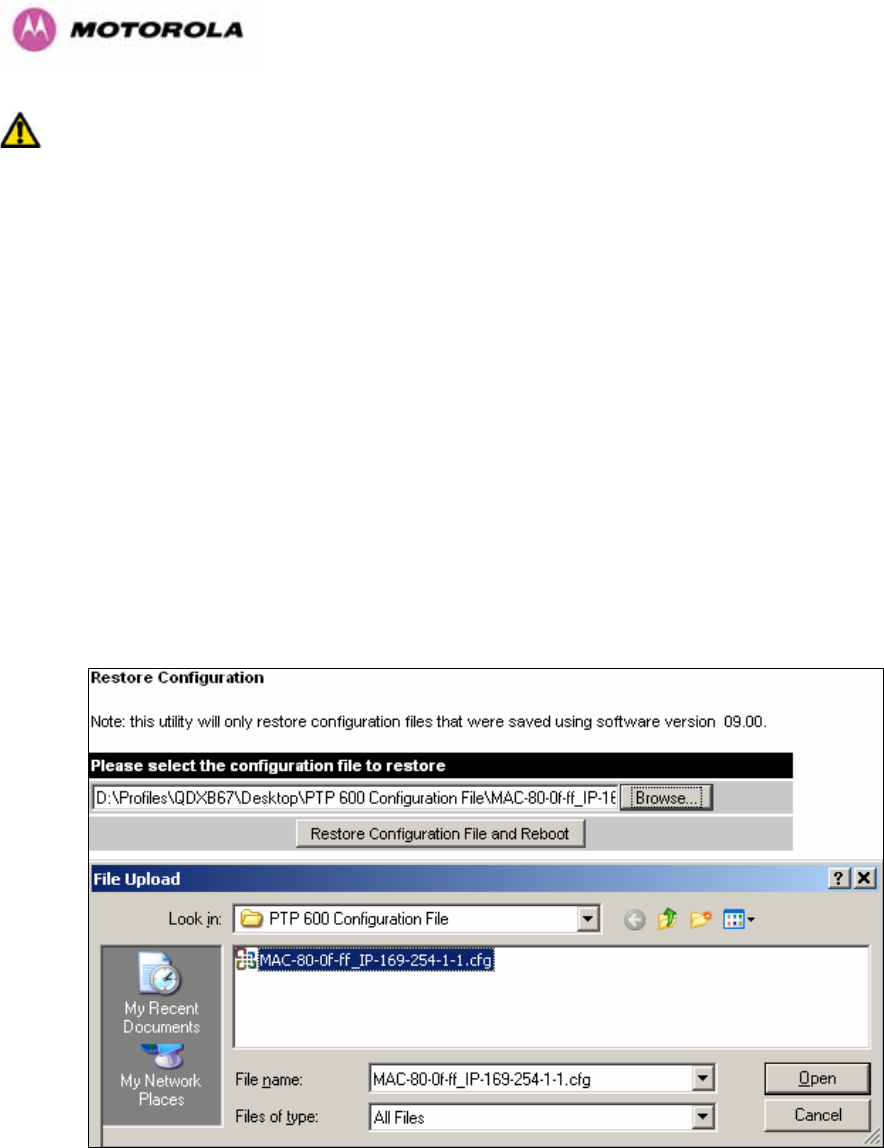
107
WARNING: The configuration file is currently restricted to a single software version and can
only be restored into a wireless unit operating the software version indicated in the
configuration file header.
The configuration file can also be used when swapping out a faulty wireless unit. If one of the
wireless units is replaced on a wireless link a configuration file captured from the faulty unit
can be replaced into the new unit to speed up replacement. It should be noted that when
placing a configuration file into a wireless unit with a different MAC Address the license key
will not be restored and may need to be entered. This can be obtained either from the Quick
Install guide supplied with replacement wireless unit or directly from Motorola. Note that the
target MAC address at the other hand needs to change.
The restoration of configuration files can be performed using the Restore configuration tool.
Using the browser button to locate the configuration file you wish to restore then click the
‘Restore Configuration File and Reboot’ button (Figure 47). The user will then be prompted to
confirm the action (Figure 48)
Figure 47 - Restore Configuration File Pop Up Screen
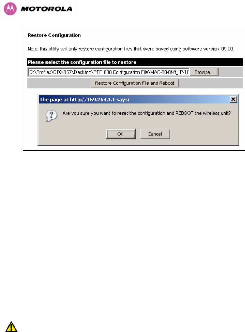
108
Figure 48 - Reset Configuration and Reboot Confirmation Pop-up
On confirmation the PTP 600 Series Bridge will:
• Upload the configuration file
• Perform data integrity checking
• Erase previous configuration
• Apply the new configuration
• Restart
After the unit has restarted the entire configuration from the configuration file will now be
active. Note: The IP address of the unit may have also been changed. The user can check
the new IP address by reading the header of the configuration file, Figure 46.
WARNING: A reboot is always required to restore a configuration file.
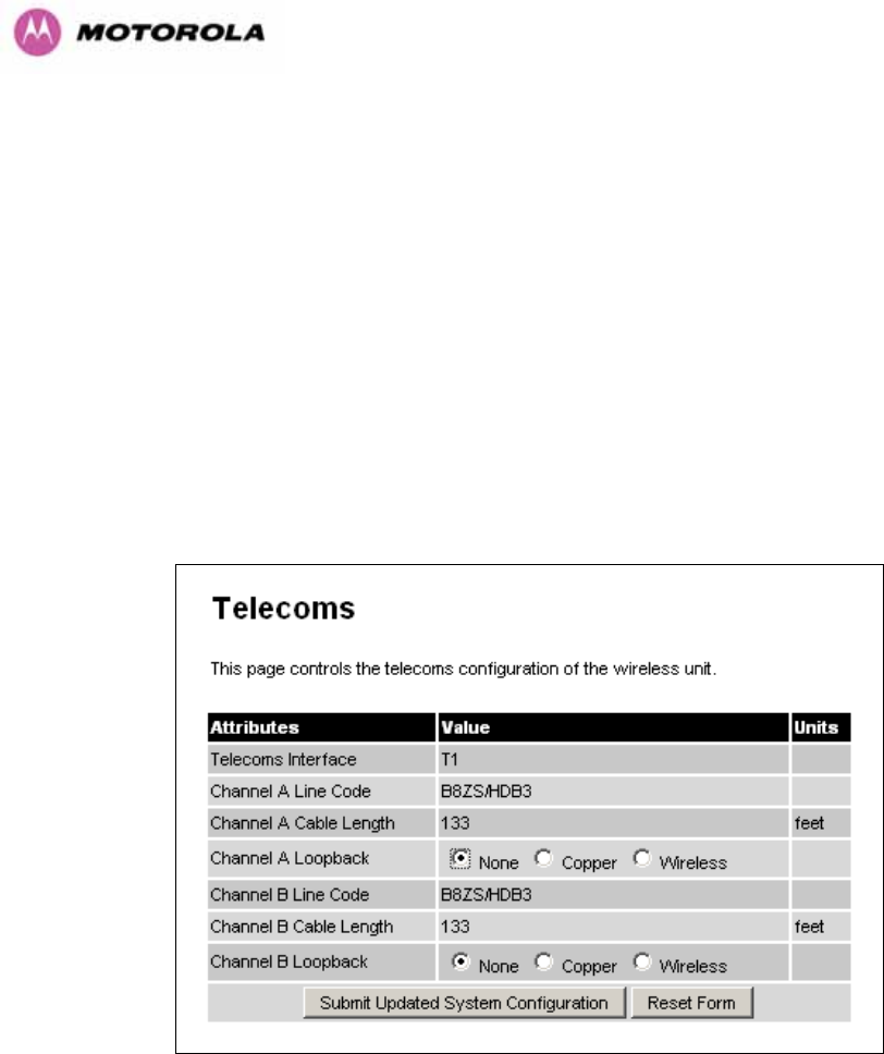
109
8.3.1.6 Telecoms Configuration Page
The Telecoms page is only available when the Telecoms Interface has been set to either T1
or E1 in the Installation Wizard.
It displays the interface setting and line code for the available telecoms channels. The PTP
600 Series Bridge is able to support two T1 or E1 channels. However, in the “Lite”
configuration one of these channels is disabled. The channels are referred to as "Channel A"
and "Channel B".
The "Channel B" configuration and controls will be displayed only when the second channel is
enabled.
Figure 49 - Telecoms Data Entry
Telecoms Interface: May be either T1, E1 reflecting the Installation Wizard setting.
Line Code: Displays the Line Code setting for each channel. The Line Code configuration
must match the configuration of the connected equipment and may be set using the
Installation Wizard.
Cable Length: The Cable Length setting is applicable in T1 mode only and shows the cable
length specified in the installation wizard.

110
Loopback: Allows the T1 or E1 data stream to be looped back at the copper or wireless
interface. During normal operation the loopback must be set to "None".
It may be helpful during installation to test the telecoms links by performing loopback
connections.
A "Copper" loopback connects the received data on a given telecoms interface to the
Transmit. A "Copper" loopback may be used, in conjunction with an appropriate test unit, to
confirm that the correct connections have been made to the ODU.
A "Wireless" loopback sends the telecoms data received across the wireless link back across
the link on the same channel. The link may be checked using, for example, a Bit Error Rate
Tester.
A typical T1 or E1 installation might include a "Copper" loopback on the local unit followed by
a "Wireless" loopback on the remote unit.
It is important to remove all loopbacks on channels for normal operation.
Alarms on the Home Page indicate the presence of loopbacks on either channel.
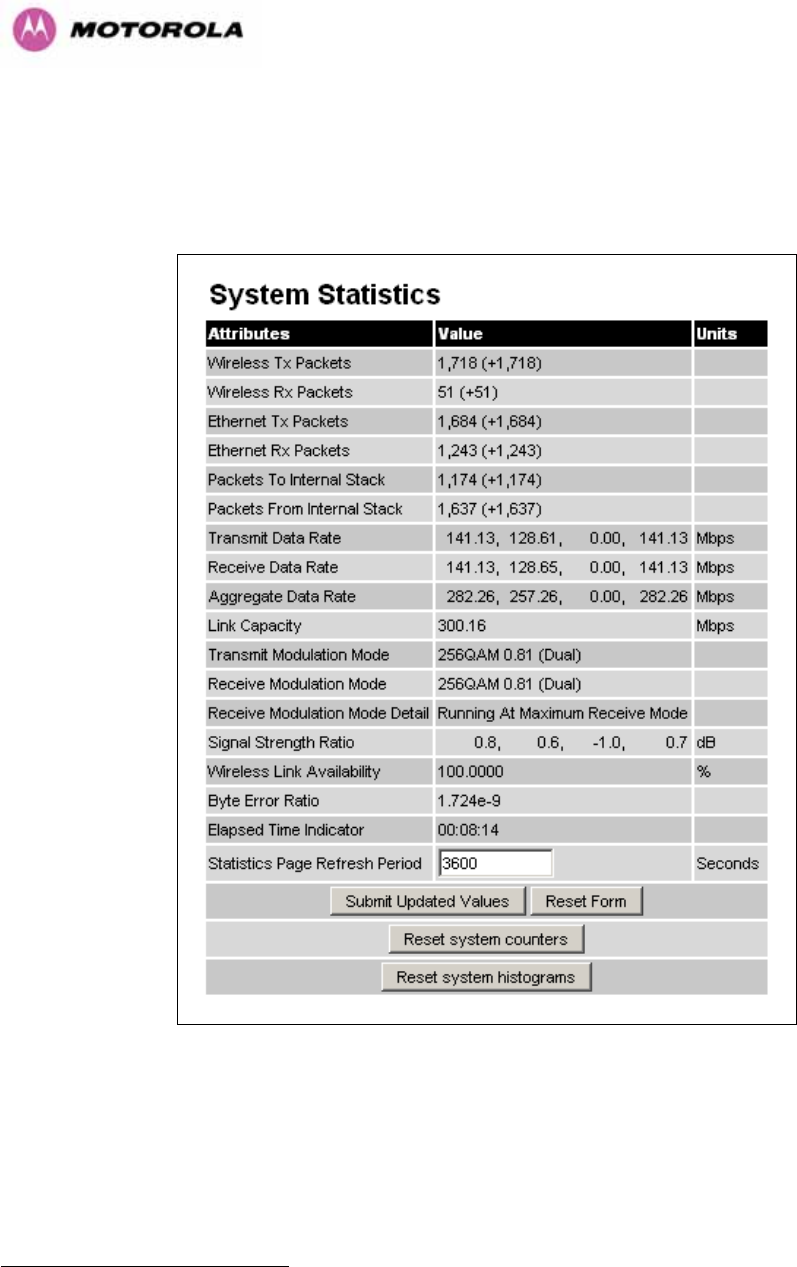
111
8.3.2 Statistics Page
The 600 Series bridge statistics page is designed to display some key statistics of the
Ethernet Bridge and the underlying wireless performance.
Figure 50 - System Statistics
Wireless Tx Packets: This displays the total number of good packets the bridge has sent for
transmission by the wireless interface20.
Wireless Rx Packets: This displays the total number of good packets the bridge has
received from the wireless interface. See note 20.
20 The number in (+nn) displays the number of packets received since the last page refresh.

112
Ethernet Tx Packets: This displays the total number of good packets the bridge has sent for
transmission by the local Ethernet interface. . See note 20.
Ethernet Rx Packets: This displays the total number of good packets the bridge has
received from the local Ethernet interface. . See note See note 20.
Packets To Internal Stack: This displays the total number of good packets the bridge has
transmitted to the internal stack (e.g., ARP requests, PING requests, HTTP requests). See
note 20.
Packets From Internal Stack: This displays the total number of good packets the bridge has
received from the internal stack (e.g. ARP responses, PING replies, HTTP responses). See
note 20.
Transmit Data Rate: The data rate in the transmit direction, expressed in Mbps and
presented as: max, mean, min, and latest histogram format. The max, min and latest are true
instantaneous measurements; the mean is the mean of a set of one second means. See Note
15. Expected data rates can be found in Section 6.1.5.
Receive Data Rate: The data rate in the receive direction, expressed in Mbps and presented
as: max, mean, min, and latest histogram format. The max, min and latest are true
instantaneous measurements; the mean is the mean of a set of one second means. . See
Note 15. Expected data rates can be found in Section 6.1.5.
Aggregate Data Rate: The sum of the data rate in the directions expressed in Mbps and
presented as: max, mean, min, and latest histogram format. The max, min and latest are true
instantaneous measurements; the mean is the mean of a set of one second means. See Note
15. Expected data rates can be found in Section 6.1.5.
Link Capacity: The maximum aggregate data capacity available for user traffic under the
current radio link conditions, assuming the units have been connected using Gigabit Ethernet.
The sum of the displayed Transmit and Receive data rates may be lower than this figure if the
link isn't fully loaded by the current traffic profile.
Transmit Modulation Mode: The modulation mode currently being used on the transmit
channel. The number in brackets after the modulation mode and coding rate string is the
effective data rate available to all MAC layer protocols. Details on the modulation modes can
be found in Section 23.1 “System Specifications”.

113
Receive Modulation Mode: The modulation mode currently being used on the receive
channel. The number in brackets after the modulation mode and coding rate string is the
effective data rate available to all MAC layer protocols. Details on the modulation modes can
be found in Section 23.1 “System Specifications”.
Receive Modulation Mode Detail: This supplies the user with information regarding the
receive modulation mode in use. Possible values are:
• Running at maximum receive mode
• Running at user-configured Target Modulation Mode
• Restricted because Installation is armed
• Restricted because of byte errors on the wireless link
• Restricted because a DFS channel change is in progress
• Restricted due to the low Ethernet link speed
• Limited by the radio conditions
Signal Strength Ratio: The Signal Strength Ratio is the ratio of the power received by the
Vertical / Horizontal receivers.
Wireless Link Availability: Expresses the link availability as a percentage of time since the
first successful registration after a system restart, expressed as a percentage to four decimal
places.
Byte Error Ratio: The ratio of detected Byte errors to the total number of bytes since the last
system reboot. This is a true measure of link quality as this measurement is made continually
using null frames when there is no user data to transport.
Statistics Page Refresh Period: The statistics page refreshes automatically according to the
setting entered here (in seconds).
Reset System Counters: By pressing this button all counters in the system are reset to zero.
Reset System Histograms: All histograms are reset, and the calculation period is restarted.
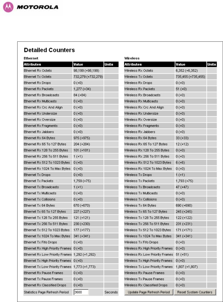
114
8.3.3 Detailed Counters Page
Figure 51 - Detailed Counters Page

115
The detailed counters page is subdivided into two columns. Column one presents the detailed
statistics for the bridge’s Ethernet interface. Column two relates to the wireless interface.
The Counters have the following definitions:
Tx & Rx Octets: Total number of octets (bytes) transmitted or received over the interface.
Rx Drops: Total number of frames dropped due to the lack of sufficient capacity in the
receive buffer.
Rx Packets: Total number of packets received by the interface. This includes both good and
bad packets.
Rx Broadcasts: Total number of good broadcast packets.
Rx Multicasts: Total number of good multicast packets.
Rx CRC and Align: Total number of packets with CRC or frame alignment errors.
Rx Undersize: Total number of packets received that are less than 64 bytes and have a valid
CRC.
Rx Oversize: Total number of packets received that are greater than the maximum number
of bytes with a valid CRC.
Rx Fragments: Total number of packets that are less than 64 bytes with an invalid CRC
(these packet types are also known as runts).
Rx Jabbers: Total number of packets received that are greater than the maximum number of
bytes with an invalid CRC.
Rx 64 Bytes: Total number 64 byte frames received
Rx 65 to 127 Bytes: Total number of frames received in the size range 65 to 127 bytes.
Rx 128 to 255 Bytes: Total number of frames received in the size range 128 to 255 bytes.
Rx 256 to 511 Bytes: Total number of frames received in the size range 256 to 511 bytes.
Rx 512 to 1023 Bytes: Total number of frames received in the size range 512 to 1023 bytes.
Rx 1024 to Max: Total number of frames received in the size range 1024 to Maximum bytes.
Tx Drops: Total number of frames dropped due excessive collisions, late collision and frame
ageing.
Tx Packets: Total number of packets received by the interface. This includes both good and
bad packets.
Tx Broadcasts: Total number of good broadcast packets.

116
Tx Multicasts: Total number of good multicast packets.
Tx Collisions: Total number frames experiencing collisions.
Tx 64 Bytes: Total number 64 byte frames transmitted
Tx 65 to 127 Bytes: Total number frames transmitted in the size range 65 to 127 bytes.
Tx 128 to 255 Bytes: Total number frames transmitted in the size range 128 to 255 bytes.
Tx 256 to 511 Bytes: Total number frames transmitted in the size range 256 to 511 bytes.
Tx 512 to 1023 Bytes: Total number frames transmitted in the size range 512 to 1023 bytes.
Tx 1024 to Max: Total number frames transmitted in the size range 1024 to Maximum bytes.
Tx FIFO Drops: Total number frames dropped due to lack of capacity in the transmit buffer,
for example when the 600 Series bridge is connected to the local Ethernet at a connection
speed of less than 1 Gbps.
Rx & Tx High Priority: Total number of received or transmitted frames marked as high
priority.
Rx & Tx Low Priority: Total number of received or transmitted frames marked as low priority.
Rx & Tx Pause Frames: Total number of received or transmitted pause frames.
Rx Classifier Drops: Total number of received frames dropped due to the application of
classifier rules.
Statistics Page Refresh Period: The statistics page refreshes automatically according to the
setting entered here (in seconds).
8.3.4 Install Pages
These pages are used during system installation. There follows a description of the install
pages along with their use during the installation configuration process. The actual installation
process is described in Section 7.7.11.
All wireless links are shipped as paired units. They are pre-configured at the factory so that
they can be installed without the user supplying any configuration. Each wireless link is
shipped with a quick start guide. Attached to the quick start guide is a summary of the pre-
configured configuration data. Table 17 shows a sample link configuration. The values
highlighted have been committed to the wireless unit’s non-volatile storage.

117
Example PTP 600 Series Configuration Data
For your convenience these two units have been pre-configured as a link
Units:
ODU serial number ODU serial number
016780000FFF 016780000FC7
Ethernet MAC address Ethernet MAC address
00:04:56:80:0F:FF 00:04:56:80:0F:C7
Configured as:
Master Slave
Target MAC address Target MAC address
00:04:56:80:0F:C7 00:04:56:80:0F:FF
License Key License Key
A471-FE88-428D-E1F3 534F-4F54-D1B0-E2DA
IP Address IP Address
169.254.1.2 169.254.1.1
Table 17 – 600 Series Bridge Factory Configuration Values
The factory default configuration is limited in range to 40 Km (25 miles). If you wish to install a
wireless link with a range of > 40 Km (> 25 miles) and < 200 Km (< 124 miles) or < 5 Km (< 3
miles) you must follow the ‘Manually Configuring The Wireless Units’ in Section 8.3.4.1.
The factory default configuration is set to Region 1. Region 1 allows the 600 Series bridge a
maximum transmit power of 25 dBm. If the local regulatory regime limits the maximum
transmit power (EIRP) to less than 25 dBm you should obtain a new license key containing
the correct region code from your local distributor or direct from Motorola. Alternatively in the
short term, you should reduce the maximum transmit power by following the procedures in
‘Manually Configuring The Wireless Units’ in Section 8.3.4.1.
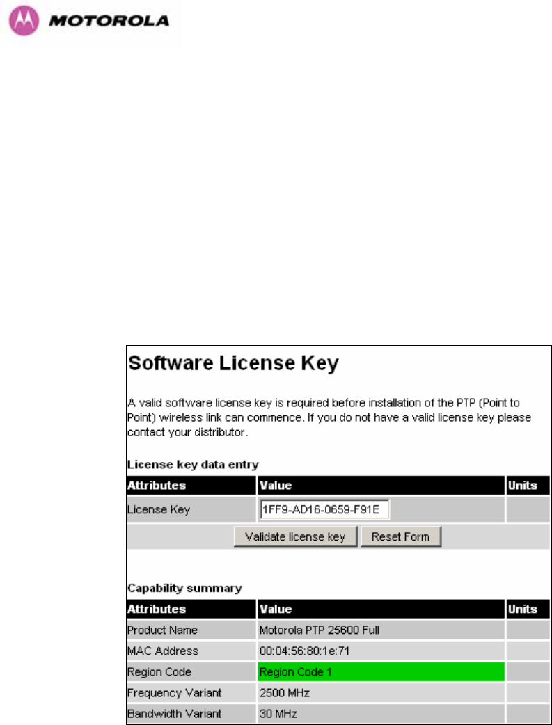
118
8.3.4.1 Manually Configuring The Wireless Units
If the installer / system administrator wishes, they may modify the default installation
configuration. If only the IP addresses (network configuration) are incorrect it is recommended
that the values are changed via the configuration menu (Section 6.3.1.2). If any other
parameters require modification then it is recommended that the system administrator use the
Installation Wizard.
A detailed description of the Installation Wizard follows:
The 600 Series bridge operational software requires a license key to enable the wireless
bridging capability and programs region code specific parameters in to the unit.
Figure 52 - License Key Data Entry
A license key is programmed into each unit during production and can be found written on the
Configuration Data Summary Label which is attached to the Quick Install Guide. If
subsequently the license key has been mislaid, replacement keys can be applied for online or
via your distributor.
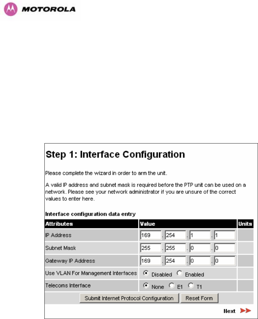
119
If a valid license key is not detected in the unit’s non-volatile memory then the user is
prompted to enter a valid key. It should be noted that 600 Series bridge units are shipped as
link pairs and, as such, valid license keys are entered during the production process. To enter
a license key simply type or paste the license key into the data entry box (Figure 52) and click
the ‘validate license key’ button.
8.3.4.2 Internet Protocol Configuration
Step 1 of the installation wizard requires the installer to enter the Internet Protocol (IP)
configuration.
Figure 53 - Installation Wizard Internet Protocol Configuration
IP Address: Internet protocol (IP) address. This address is used by the family of Internet
protocols to uniquely identify this unit on a network.
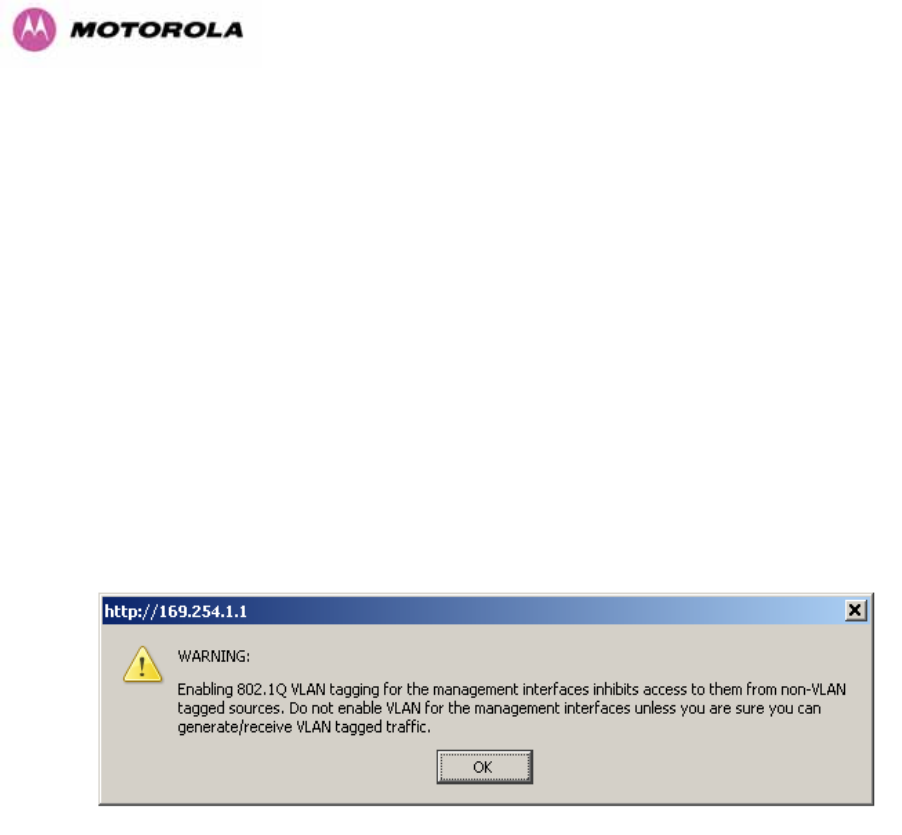
120
Subnet Mask: A subnet allows the flow of network traffic between hosts to be segregated
based on a network configuration. By organizing hosts into logical groups, subnetting can
improve network security and performance.
Gateway IP Address: The IP address of a computer / router on the current network that acts
as a gateway. A gateway acts as an entrance / exit to packets from / to other networks.
Use VLAN Management Interface: Controls whether the management interfaces
(HTTP/SNMP/SMTP/SNTP) use a VLAN. Selecting this option presents the user with extra
fields in which to enter the Management VLAN ID, Priority and whether to validate the VLAN
ID. If the user modifies this control, a warning dialog is displayed see Figure 54.
Telecoms Interface This allows the activation of the 600 Series bridge telecoms interface. If
the selection options are disabled, T1 or E1 note mixed T1/E1 configurations are not
permitted.
Figure 54 - VLAN Warning
Once complete, click the ‘Submit Internet Protocol Configuration’ button or the ‘Next’ link.
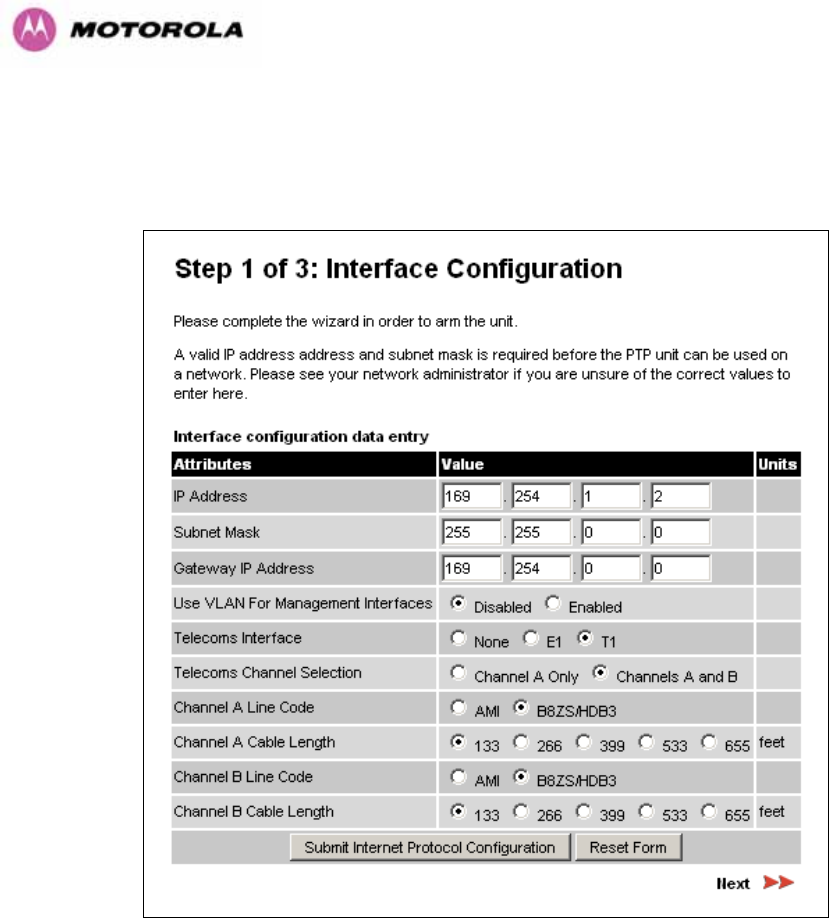
121
8.3.4.3 Telecoms Interface
If the telecoms interface is configured to either T1 or E1 then the web page will reconfigure
itself with the following additional configuration options.
Figure 55 - Telecoms Configuration Interface
Telecoms Channel Selection: This controls the selection of the telecoms interface standard
supported options or T1 and E1.
Channel A Line Code: The line code setting of the telecoms interface. This must match the
setting of the device connected to this interface.
Channel B Line Code: The line code setting of the telecoms interface. This must match the
setting of the device connected to this interface.
Cable Length: This field is applicable to the T1 operating mode only. It configures the T1
transceiver to output a signal suitable for driving a cable of the specified length. This should
be set to reflect the length of cable between the wireless unit and the connected equipment.
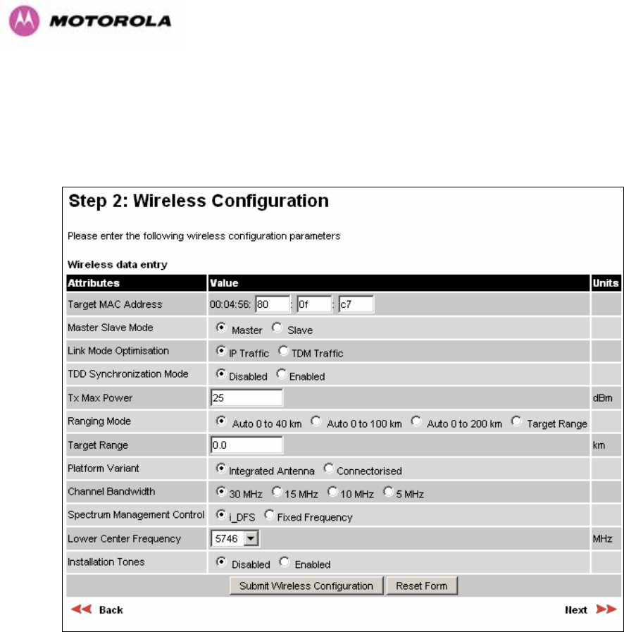
122
8.3.4.4 Wireless Configuration
Step 2 of the installation wizard requires the installer to enter the wireless configuration
parameters.
Figure 56 – 5.8 GHz and 5.4 GHz Variants - Installation Wizard Wireless Configuration
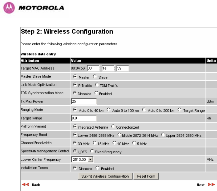
123
Figure 57 - 2.5 GHz Variant - Installation Wizard Wireless Configuration
Target MAC Address: It is the MAC Address of the peer unit that will be at the other end of
the wireless link. This is used by the system to ensure the unit establishes a wireless link to
the correct peer.
The MAC Address can be found embedded within the serial number of the unit. The last six
characters of the serial number are the last three bytes of the unit’s MAC address.
(Note: A PTP 600 Series system is shipped as a pair of units with pre-loaded correct MAC
addresses. MAC addresses will only need to be entered if an existing unit has to be replaced
in the field or the units configuration has been erased).
Master Slave Mode: At this point it is necessary to decide which end will designate a Master.
The Master unit is the controlling unit with respect to the point-to-point link and its
maintenance. The master transmits until the link is made, while the Slave listens for its peer
and only transmits when the peer has been identified.

124
Link Mode Optimization: Optimizes the link behavior according to the type of traffic that will
be bridged.
TDD Synchronization Mode: Enables the TDD Synchronization feature (see Section 5.8 for
basic description and Section 14 for installation and configuration details).
Tx Max Power: This attribute controls the maximum transmit power the unit is permitted to
use when installing and executing the wireless link. The maximum setting for a particular
region or country is controlled by the License Key.
Ranging Mode: During installation, the wireless units perform “Automatic Ranging”. The
ranging mode allows the installer to control the behavior of the system’s automatic ranging
algorithms. The default value is 0 to 40 km21 (0 to 25 miles). If the installer is required to
install a link of greater than 40 km (25 miles) then the ranging mode attribute MUST be
configured to ‘0 to 100km’ (0 to 62 miles) or ‘0 to 200km’ (0 to 124 miles) mode depending on
the range of the link.
Target Range: Installers that know the range between the two wireless units to within ± 1 km
can use the target range mode. The main advantage of the target range mode is that it
reduces the time taken by the units to range. To use the target range mode the installer
MUST select Target Range as the ranging mode and enter the approximate range in km in
the Target range data entry field at both ends of the link.
Platform Variant: Chooses between an integrated unit or a connectorized unit that requires
an external antenna.
Frequency Band: This is for the 2.5 GHz product variant which operates in one of three
bands as described in Section 5.4.
Channel Bandwidth: Users can choose a variable channel bandwidth for the available
spectrum. Values of 5 MHz, 10 MHz, 15 MHz and 30 MHz can be selected.
21 If preferred PTP 600 Series Bridge range functions can be configured to operate in miles, see the
page in Section 8.3.15.
Properties

125
Spectrum Management Control: Is used to configure the PTP 600 Series Bridge’s
Spectrum Management features, see Section 8.3.7 for more details. i-DFS is the abbreviation
for intelligent Dynamic Frequency Selection. This feature continually monitors the spectrum
looking for the channel with the lowest level of on channel and co-channel interference. Fixed
frequency mode allows the installer to fix transmit and receive frequencies on the units. The
frequencies may be configured symmetrically or asymmetrically.
Lower Center Frequency: The software for the PTP 600 Series Bridge allows a user to
optionally adjust the channel center frequencies. Changing the Lower Center Frequency
attribute causes all channel center frequencies to be offset. It effectively slides the
channelization up or down. See Sections 5.4 and 5.7 for more detail.
Warning: The lower center frequency attribute must be configured to the same value for both
the master and slave. Failure to do so will cause the wireless link to fail reestablishment. The
only way to recover from this situation is to modify the Lower Center Frequency attribute so
that they are identical on both the master and slave unit.
Fixed Transmit Frequency, Fixed Receive Frequency: The software for the PTP 600
Series Bridge allows a user to optionally fix the Transmit and the Receive frequencies for a
wireless link. The settings must be compatible at each end of the link. Once configured the
spectrum management software will not attempt to move the wireless link to a channel with
lower co or adjacent channel interference. Therefore this mode of operation is only
recommended for deployments where the installer has a good understanding the prevailing
interference environment. Figure 58 shows a sample fixed frequency configuration for a 30
MHz channel bandwidth. In the example the lower center frequency is set to its default values
and the Fixed Transmit Frequency is set to 5742 MHz and the Fixed Receive Frequency is
set to 5742 MHz. Care must be taken when configuring the Fixed Transmit and Receive
Frequencies to ensure that both frequencies are on the same 10 MHz channel raster as the
Lower Center Frequency. For example both the Fixed Transmit and Receive Frequencies
must be a multiple of 10 MHz from the Lower Center Frequency (5752 = 5742 + 10 MHz) and
(5782 = 5742 + 10 MHz × 3). See Sections 5.4 and 5.7 for more detail.
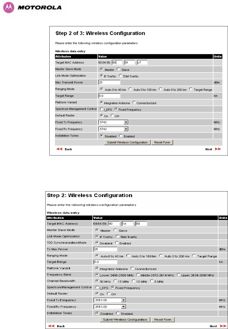
126
Figure 58 – 5.8 GHz and 5.4 GHz Variants - Fixed Frequency Operation
Figure 59 - 2.5 GHz Variant - Fixed Frequency Operation
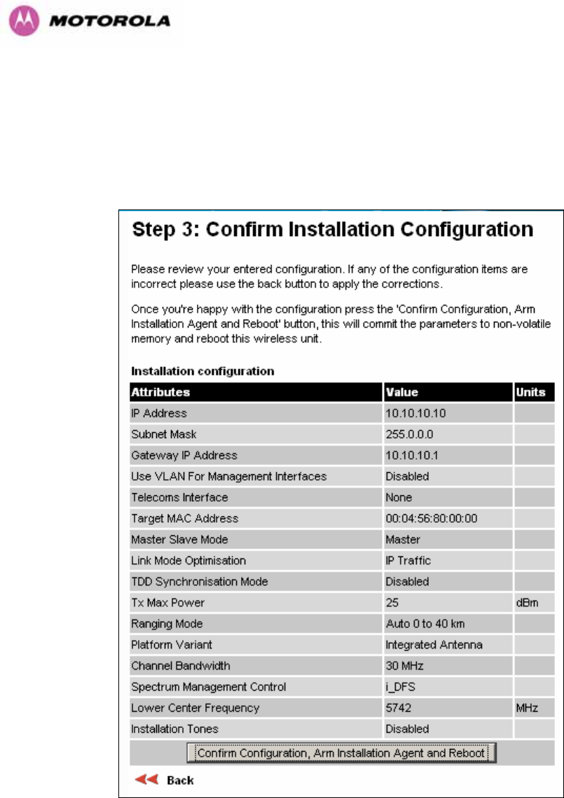
127
Installation Tones: Where the use of audio installation tones is not required this control
allows the installer to optionally disable the tone generator during the installation process.
Once the installer is satisfied with the wireless configuration options then the “Submit
Wireless Configuration” button or the “Next” link should be clicked.
Figure 60 – 5.8 GHz and 5.4 GHz Variants - Installation Wizard Confirm Configuration
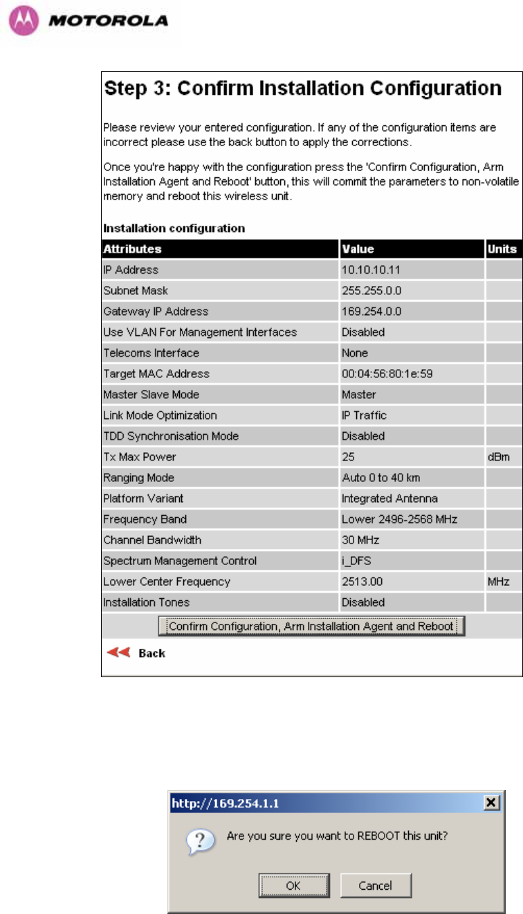
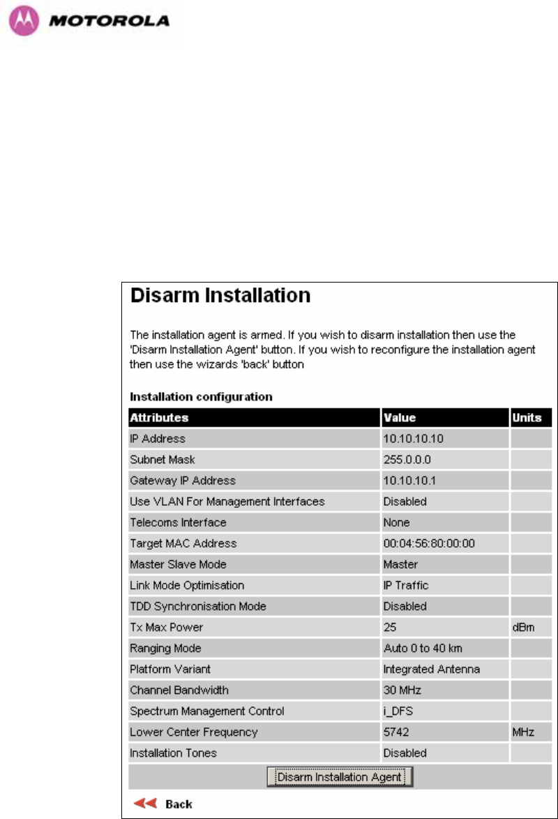
129
All the attributes are committed to non-volatile memory. Immediately following the write to
non-volatile memory the unit is reset.
Note: If you have changed the Ethernet parameters you must reconnect using the correct
network and address settings.
8.3.4.5 Disarm
Step 5 of the installation wizard is the disarm phase.
Figure 63 – 5.8 GHz and 5.4 GHz Variant - Disarm Installation
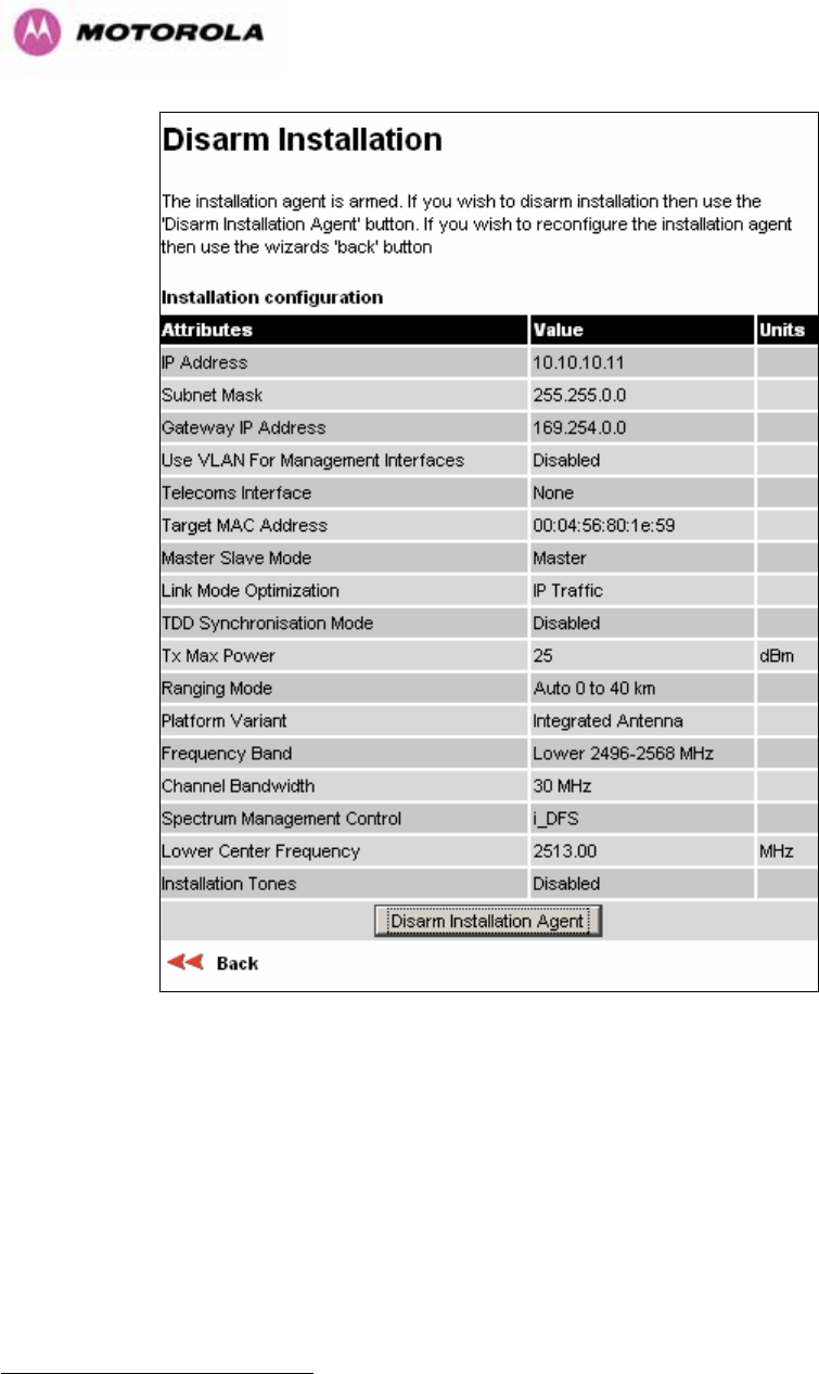
130
Figure 64 - 2.5 GHz Variant - Disarm Installation
Once Section 8.3.4.4 is complete pressing the “Disarm Installation Agent” button completes
the installation process22 and the audible installation tone will be switched off. If the installer
wishes to modify the installation configuration then the ‘Back’ link can be used to access the
installation wizard steps described above.
22 The installation process is completed when both ends of the link are ‘disarmed’.
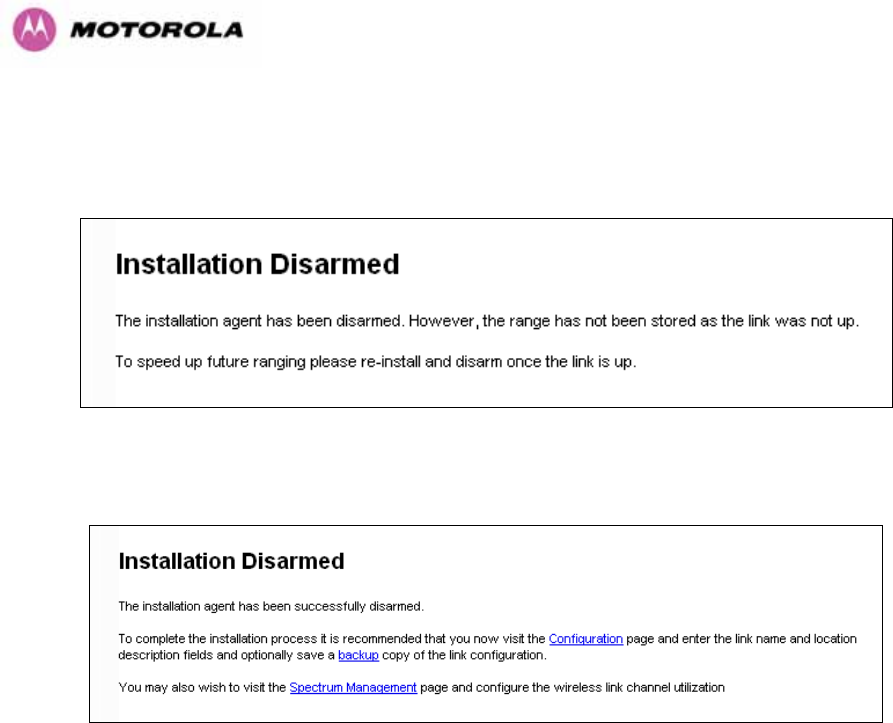
131
After disarming the wireless link the user is presented with one of two possible configuration
pages, see Figure 65 and Figure 66. The screen presents hyperlinks to the main
configuration and spectrum management pages.
Figure 65 - Optional Post Disarm Configuration 1
Figure 66 - Optional Post Disarm Configuration 2
After installation the system administrator may wish to modify the wireless units descriptive
configuration (link name and link location). In addition the system administrator may wish to
change the spectrum management configuration of the wireless unit, or look at the analysis of
the 5.8 GHz spectrum to see if the automatic channel selection is appropriate for the system
administrator’s network. It is also recommended that a backup copy of the wireless units
configuration is taken. Hyperlinks are provided on the post disarm page for ease of use.
8.3.5 Graphical Install
To aid the installation of wireless links two graphical installation aids have been introduced in
this 600 Series system version.
• A PDA installation screen
• A larger installation screen available from the main HTTP management interface.
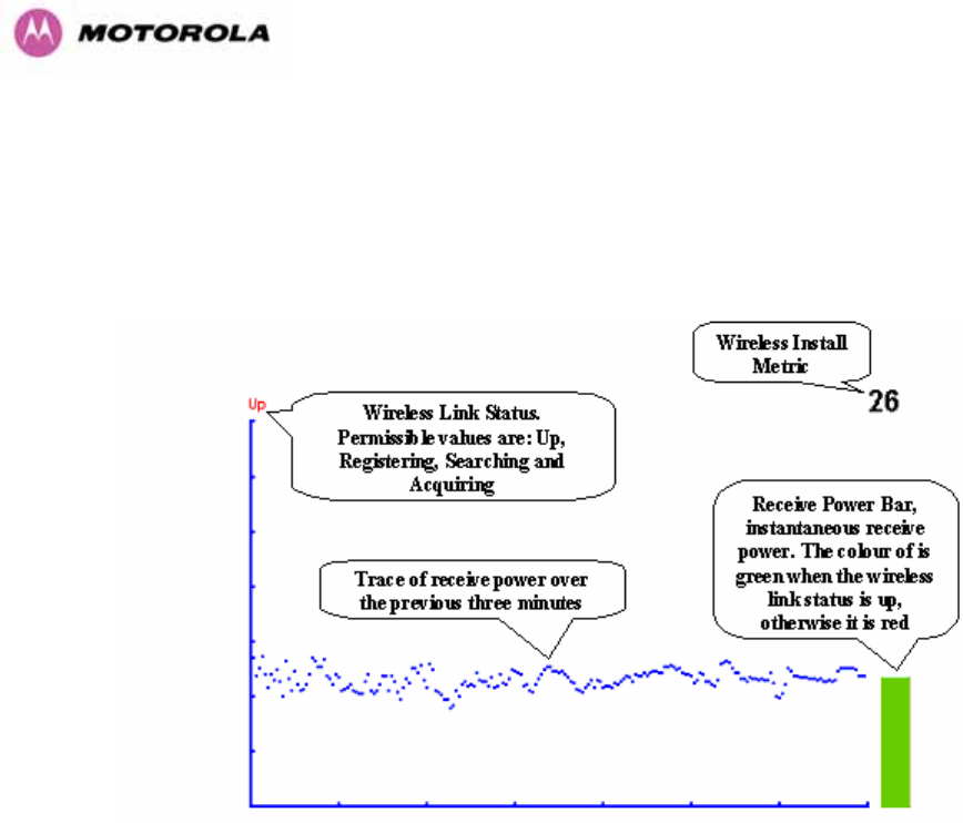
132
The design of the installation screen has been deliberately kept simple and uncluttered. An
example of the installation screen is shown in Figure 67. Both the PDA and the large format
installation screen have the same content and only differ in size. The PDA installation screen
is 232 by 220 pixels to be compatible with the typical size of a PDA screen.
Figure 67 – Graphical Installation Screen
The screen displays the receive power over the last three minutes. This will allow the installer
to slowly sweep the antenna during installation and monitor the variation in signal strength
with angular position. The screen automatically refreshes every three seconds.
The screen also displays the current state of the wireless link in two ways. First, the actual
state of the wireless link is written in the top left corner of the screen. The instantaneous
receive power bar also encodes the state of the wireless link using green to signify that the
wireless link is up and red for all other states.
For the more technically, aware the installation metric is simply the instantaneous receive
power in dBm + 100.
The PDA installation tool is accessed via a hidden URL http://<ip-address>/pda.cgi. It should
be noted that this link is only available after the user has logged in as system administrator.
The large screen version of the graphical user interface is available as a submenu option of
the installation wizard.
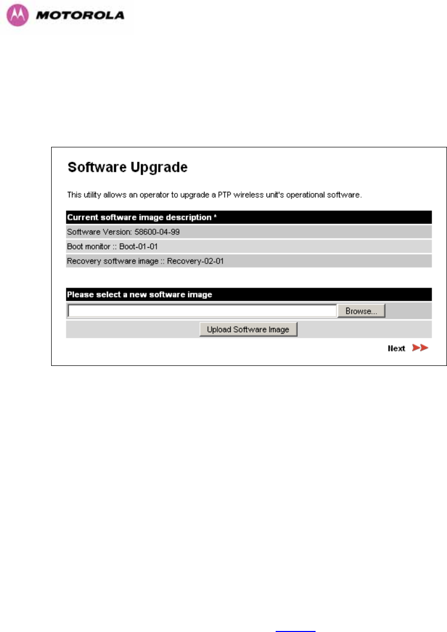
133
8.3.6 Software Upgrade
The 600 Series system has two software image banks; one is a fixed image which is stored in
protected non-volatile memory and cannot be modified by the user. The second bank is used
by the system administrator to upgrade the firmware when necessary. Figure 68 shows the
main software upgrade web page.
Figure 68 - Software Upgrade
The ‘Fixed’ or ‘Recovery’ image is used by the System Administrator to:
o Reset Ethernet configuration to default settings
o Erase Configuration
o Upgrade software
For a full description of the Recovery image see Section 9.
The software upgrade pages are used to update a unit’s operational software. The software
image to be uploaded should be downloaded to local storage from the Motorola web site. The
software image is delivered by Motorola as a compressed zip file. Once the zip file has been
downloaded, the user should extract the PTP 600 Series Software image, identifiable by its
‘.dld’ file extension.
The first step (Figure 68) is to use the “Browse” button to locate the software image
previously downloaded to local storage from the Motorola web site. Once the image is
located, the user should press the “Upload image to wireless unit” button to start the software
upgrade process.
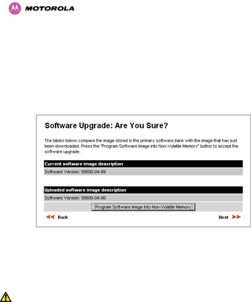
134
The software image will now be uploaded to the unit. This upload should only take a few
seconds. Once complete the image is verified and validated to ensure that no errors occurred
during transfer and that the image is valid to run on the current platform. If there are any
problems a warning screen will appear.
The unit being upgraded will now display information about the build it currently has stored in
the image bank and the one that’s just been uploaded. If the image is not the right one, the
user has the option to go back and reload a new image. (See Figure 69)
Figure 69 - Software Upgrade Image Check
The user should ensure that the correct image is shown before pressing the “Program
Software Image into Non-Volatile Memory” button. Once this button has been pressed the
image is stored into non-volatile memory, this process can take up to 60 seconds and must
not be interrupted.
If the upgrade process is interrupted during the erasure of the image bank, or during the
reprogramming of the image bank, the image bank will be left in a corrupt state. If this occurs
the software must be reloaded. All software images that are stored in non-volatile memory are
protected via the use of CRCs. If the software detects an invalid CRC the image bank is
marked as ‘corrupt’ and the 600 Series bridge boot code will boot the fixed software image. If
this occurs the user must attempt to reload the correct version of software.
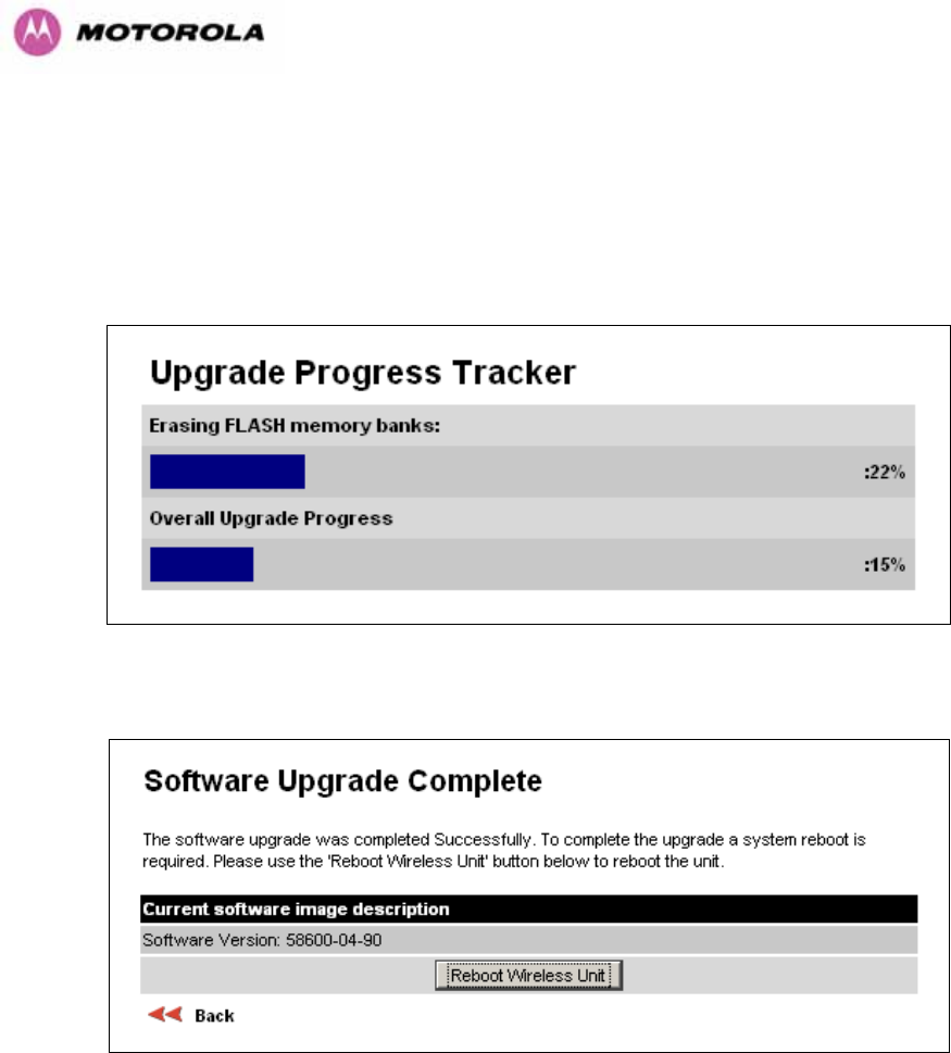
135
During the write process the progress of the upgrade is displayed on the progress tracking
page (Figure 70). The upgrade process should not be interrupted. Interruption of this process
can result in a corrupt main software image, which will result in the recovery image been
booted at the next reset cycle.
Figure 70 - Software Download Progress Indicator
Figure 71 - Software Upgrade Complete
When the software image has been written to non-volatile memory Figure 71 will be displayed
showing the status of the software upload.


137
This will reboot the unit, taking up to 120 seconds. During this time you will not be able to
communicate with the unit.
If you cannot communicate with the unit after 120 seconds, this could indicate a problem with
the memory update process. Under these circumstances the user should enter “Recovery
Mode”, see Section 9.
After the reboot the user should check that the required software image is loaded and
running.
NOTE: Please ensure that you are upgrading the correct units. Units cannot be downgraded
and license keys cannot be swoped once upgraded.
8.3.7 Spectrum Management
Spectrum Management Selection is the PTP 600 Series Bridge feature that monitors the
available wireless spectrum and directs both ends of the wireless link to operate on a channel
with a minimum level of co-channel and adjacent channel interference.
8.3.7.1 Wireless Channels
The PTP 600 Series Bridge operates using a set of predefined overlapping channels. There
are a different number of channels, depending on the raster mode selected. Each channel
occupies 30 MHz, 15 MHz, 10 MHz or 5 MHz of wireless spectrum and is offset in center
frequency from its neighboring channel by 10 MHz or 6 MHz. It is important to note that
adjacent channels on the Spectrum management display have a 10 MHz or 6 MHz overlap to
the adjacent channel.
The default channelization can be modified by varying the lower center frequency attribute in
the installation wizard - see Section 8.3.4.4. See Section 5.4 and 5.7 for more detail.

138
8.3.7.2 Spectrum Management Measurements
The 600 Series Bridge performs two mean signal measurements per TDD cycle, per channel.
This mean measurement represents the mean received signal power for the 40 μS
measurement period.
The Spectrum Management algorithm collects measurements equally from all channels. This
process is called the Channel Availability Check (hereafter referred to by the acronym CAC).
The CAC uses a round-robin channel selection process to collect an equal amount of
measurements from each channel. It is important to note that the CAC measurement process
is not altered by the channel barring process. Measurements are still collected for all
channels irrespective of the number of barred channels.
8.3.7.3 Measurement Analysis
Spectrum Management uses statistical analysis to process the received peak and mean
measurement. The statistical analysis is based on a fixed, one minute, measurement
quantization period. Spectrum Management collects data for the specified quantization period
and only at the end of the period is the statistical analysis performed.
The analysis produces three key metrics for each channel:
o Peak of Means
o 99.9% Percentile of the Means
o Mean of Means
Peak of Means is the largest mean interference measurement encountered during the
quantization period. The peak of means is similar to the peak of peaks and is useful for
detecting slightly longer duration spikes in the interference environment.
99.9% Percentile of the Means is the value of mean interference measurement which 99.9%
of all mean measurements fall below, during the quantization period. The 99.9% percentile
metric is useful for detecting short duration repetitive interference that by its very nature has a
minimal effect of the mean of means.

139
Mean of Means is the arithmetic mean23 of the measured means during a quantization
period. The mean of means is a coarse measure of signal interference and gives an
indication of the average interference level measured during the quantization period. The
metric is not very good at predicting intermittent interference and is included to show the
spread between the mean of means, the 99.9% percentile and the peak of means.
Important Note: Spectrum Management uses the 99.9% percentile as the prime interference
measurement. All subsequent references to interference level refer to this percentile
measurement.
The display of statistical measurement on the spectrum management page always shows a
statistical summary of all channel measurement. The statistical summary is controlled by the
Statistics Window attribute. This attribute defaults to a value of twenty minutes, which means
that the mean and percentile values displayed for each channel are calculated over the 20
minute period. All channel decisions are made using the values computed over the statistics
window period.
8.3.7.4 The Spectrum Management Master / Slave Relationship
By default Spectrum Management operates in a master / slave relationship. The master is
assumed to be the link master configured during installation. All Spectrum Management
configuration changes MUST be performed from the master. To enforce this, the Spectrum
Management web page has a different appearance depending if you are viewing the data
from the master or slave.
All configuration changes are applied at the master only. These changes are then messaged
from the master to the slave. Any Spectrum Management configuration messages received at
the slave are stored in non-volatile memory. This enables both master and slave to keep
identical copies of Spectrum Management configuration data in their non-volatile memories. It
is therefore possible to swap master and slave roles on an active Point-to-Point link without
modifying Spectrum Management configuration.
23 The arithmetic mean is the true power mean and not the mean of the values expressed in dBm.
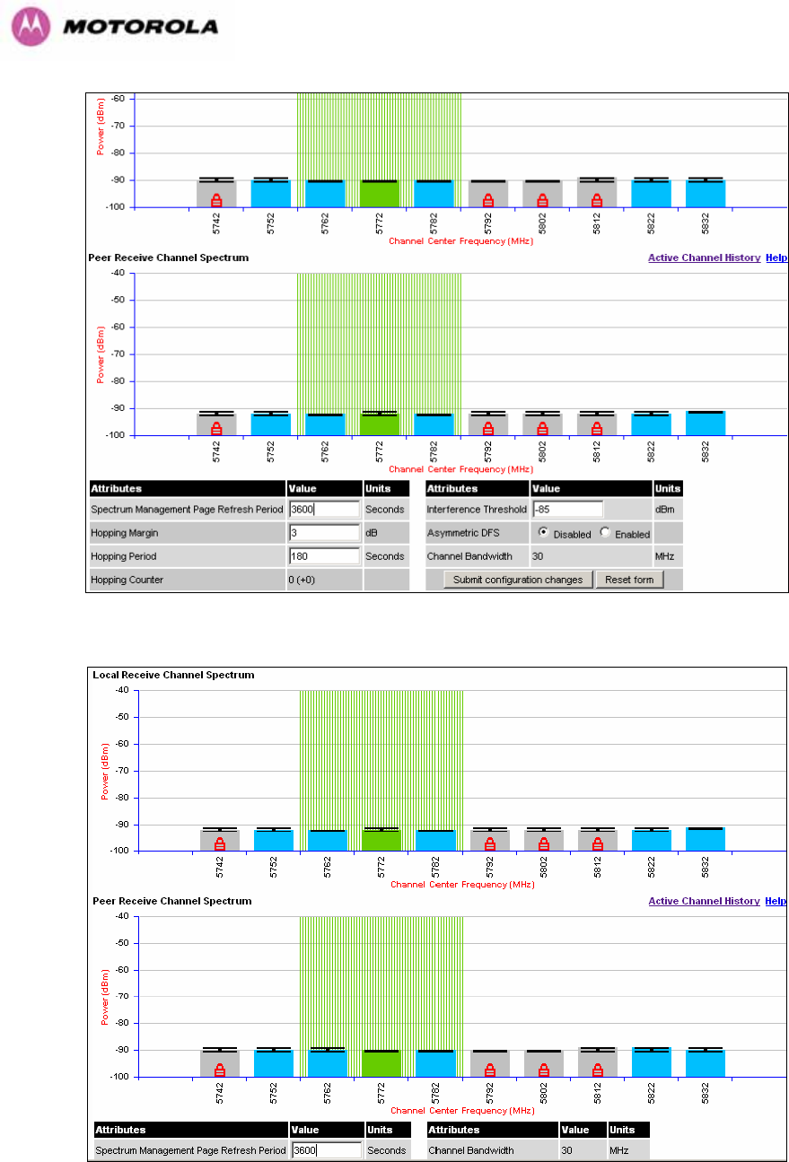
140
Figure 73 - Spectrum Management as seen from the Master
Figure 74 - Spectrum Management as seen from the Slave

141
Figure 73 shows an example Spectrum Management webpage as seen from the master.
Figure 74 shows an example Spectrum Management webpage as seen from the slave. It
should be noted that the key configuration attributes are not available on the slave web page.
8.3.7.5 Spectrum Management Configuration
The following section describes the user modifiable configuration accessible from the
Spectrum Management webpage. It is recommended that the default values are maintained.
If the user believes that the performance of the Spectrum Management algorithm requires
some modifications this should only be done after consulting your Motorola Point-to-Point
distributor or one of the system field support engineers.
Page Refresh Period: The page refreshes automatically according to the setting entered
here (in seconds).
Hopping Margin: Spectrum Management uses this margin when making a channel hop
decision. The target channel has to have an interference level 3 dB (default) better than the
current active channel.
Hopping Period (not configurable): The Spectrum Management algorithm evaluates the
metrics every ‘Hopping Period’ seconds (180 seconds by default) looking for a channel with
lower levels of interference. If a better channel is located, Spectrum Management performs
an automated channel hop. If SNMP or SMTP alerts are enabled an SNMP TRAP or an email
alert is sent warning the system administrator of the channel change.
Hopping Counter: is used to record the number of channel hops. The number in the “(+)”
brackets indicates the number of channel changes since the last screen refresh.
Interference Threshold: Spectrum Management uses the interference threshold to perform
instantaneous channel hops. If the measured interference on a channel exceeds the specified
threshold, then iDFS will instruct the wireless to immediately move to a better channel. If a
better channel cannot be found the 600 Series Bridge will continue to use the current active
channel. (Default –85 dBm)
Asymmetric DFS: The default configuration of symmetric operation constrains the link to
operate symmetrically, using the same transmit and receive channels. When in symmetric
mode the slave unit will always follow the master. If the master moves to a new channel the
slave will hop to the same channel. When the Point-to-Point link is configured as an
asymmetric link both the master and slave are free to select the best channel from their own
set of local interference metrics.
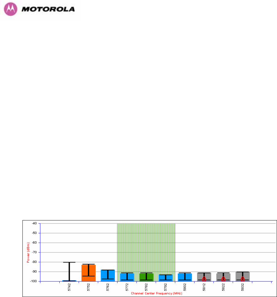
142
Channel Bandwidth (not configurable): shows the value of the variable channel bandwidth
selected.
8.3.7.6 Barring Channels
Channels can only be barred / unbarred by the system administrator from the master
Spectrum Management web page. The barring / unbarring operations are disabled on the
slave web page. If an attempt to bar / unbar a channel is made at the slave, a warning dialog
is generated.
Barring/Unbarring of channels is performed by clicking the appropriate channel on the local or
peer channel spectrum plots on the master web page. Each bar / unbar attempt will be
proceeded by a confirmation dialog. It should be noted that the channel bar will take effect
immediately and is not related to the measurement quantization period.
8.3.7.7 Local and Peer Channel Spectrum Graphics
Spectrum Management presents its computed statistical measurements in a graphical display
on both the master and slave Spectrum Management web page.
Figure 75 - Example Spectrum Management Graphic
The X-axis shows a stylized view of the 9 or 10 selectable wireless channels. It is important
to note that adjacent channels on the display have a 10 MHz overlap. The display separates
the display of channels to help the clarity of the resultant display. The axis is labeled using the
channel center frequencies in MHz.
The Y-axis shows the interference power levels from –100 to –40 dBm.

143
The active channel (channel 5 in Figure 75) is always marked using hatched green and white
lines. The width of the hatching is directly proportional the 30 MHz spectral occupancy of the
channel.
The individual channel metrics are displayed using a colored bar and an ‘I’ bar.
The colored bar represents the following channel state:
Green Active The channel is currently in use, hosting the Point-to-Point
wireless link
Orange Interference The channel has interference above the interference threshold
Blue Available The channel has an interference level below the interference
threshold and is considered by the Spectrum Management
algorithm suitable for hosting the Point-to-Point link
Grey Barred The system administrator has barred this channel from use.
For improved visibility, an additional red ‘lock’ symbol is used
to indicate that a channel is barred.
Table 18 - Spectrum Management change state key
The top of the colored bar represents the 99.9% percentile metric for specific channel.
The ‘I’ Bar is used to display the mean of means and peak of means metrics. The lower
horizontal bar represents the mean of means and the upper horizontal bar represents the
peak of means. The vertical bar is used as a visual cue to highlight the statistical spread
between the peak and the mean of the statistical distribution.
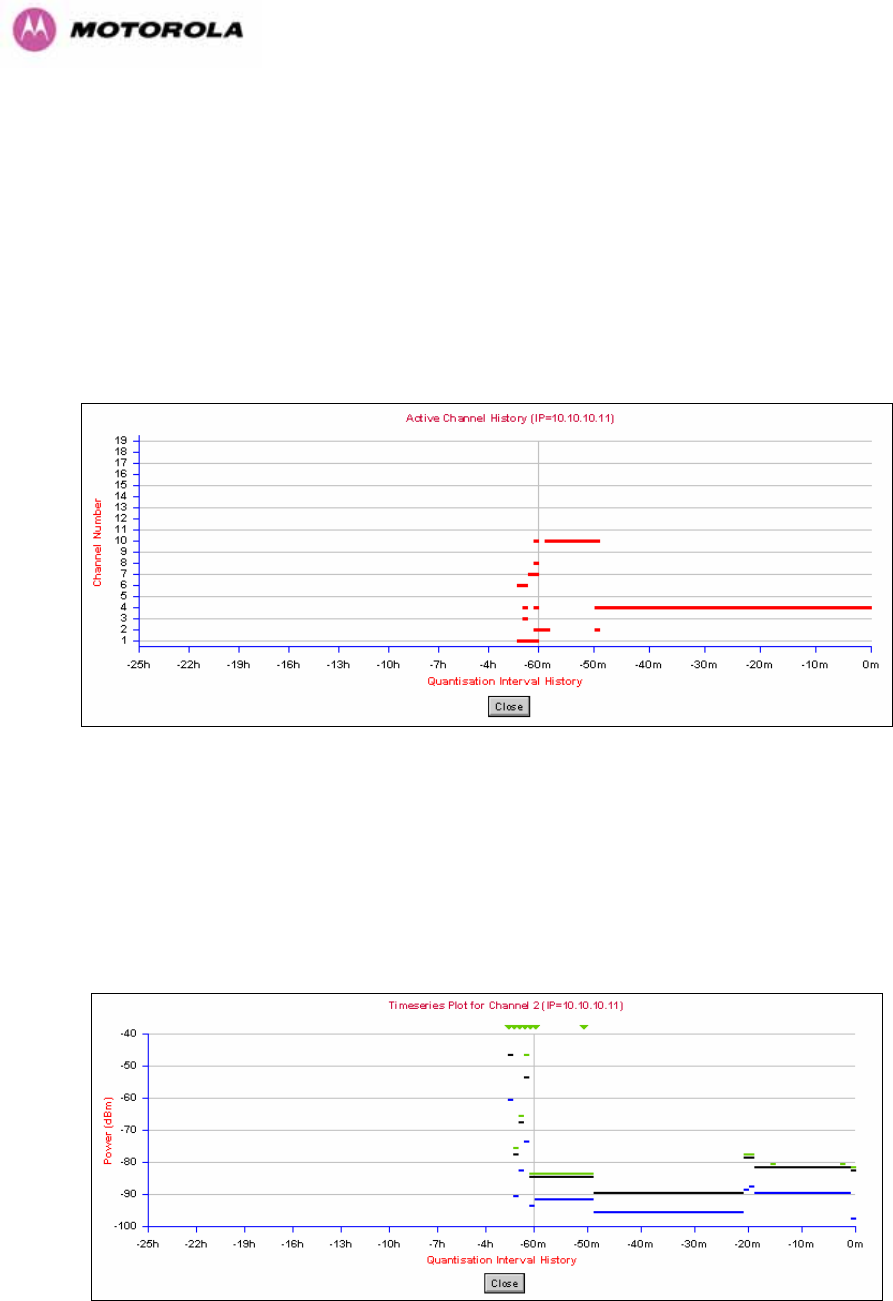
144
8.3.7.8 Active Channel History
The active channel history is a time series display of the channels used by the PTP 600
Series Bridge over the last 25 hours. The active channel history is activated from the main
Spectrum Management page using the ‘Active Channel History’ hyperlink. An example of the
active channel history display is shown in Figure 76. Where there are parallel entries on the
display this signifies that the wireless link occupied this channel during the measurement
period. The measurement periods are one minute (from zero to sixty minutes) and twenty
minutes from (60 minutes to twenty five hours).
Figure 76 - Active Channel History Screen
8.3.7.9 Viewing Historic Spectrum Management Metrics
Spectrum Management allows the system administrator to view the results of previous
measurement quantization periods. Holding down the shift key and clicking the appropriate
channel on the local channel spectrum plots activates this feature. This feature is available on
both the master and slave web page.
Figure 77 - Spectrum Management Time Series Plot

145
Figure 77 shows an example time series plot. A time series plot displays the previous 132
measurement quantization periods. If the PTP 600 Series Bridge has not been running for
132 quantization periods then only the number of measurement quantization periods that are
available are displayed.
GREEN Peak of Means interference measurement
BLACK 99.9% percentile of means interference measurement
BLUE Mean of Means interference measurement
Table 19 - Spectrum Management Time Series Key