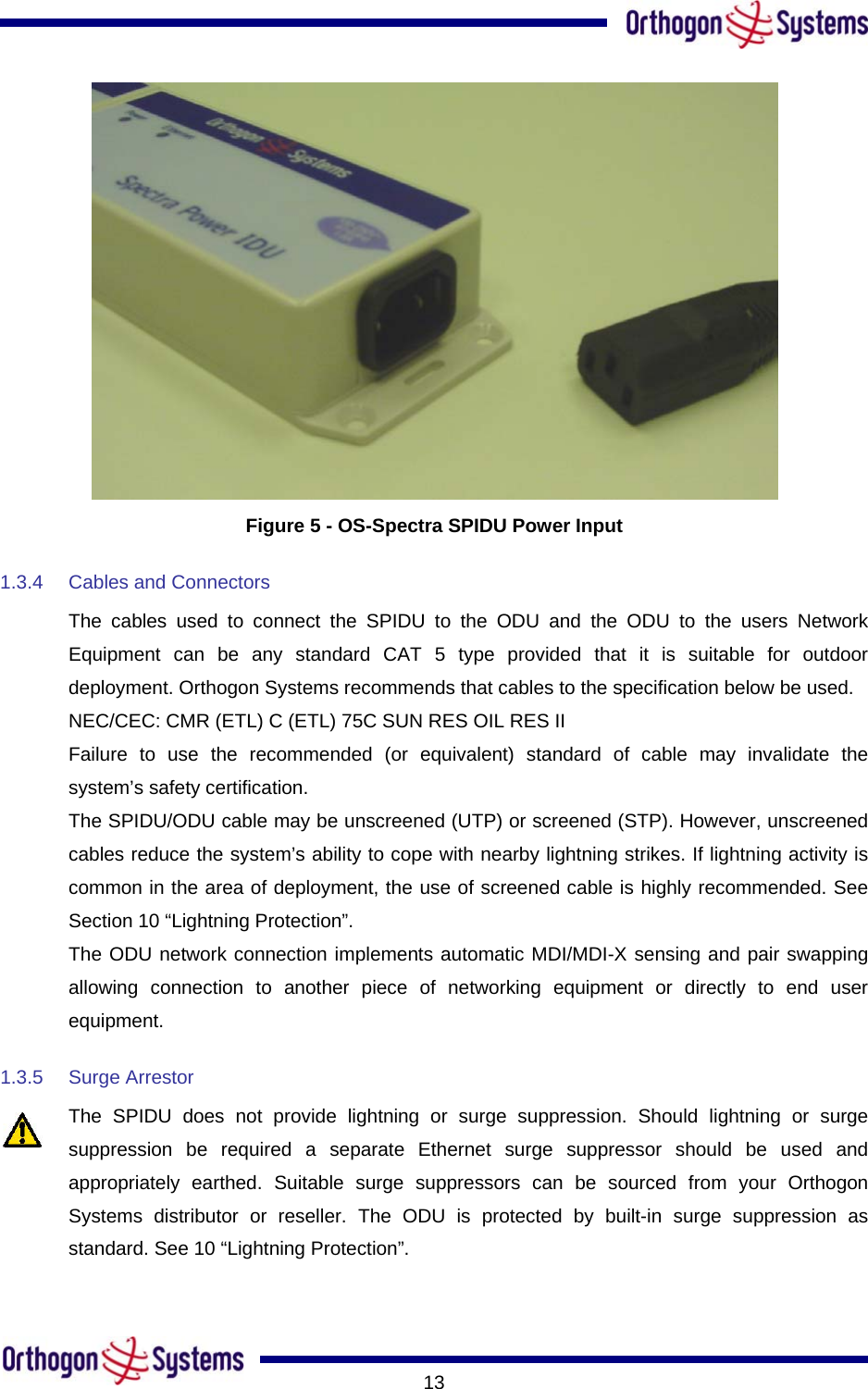
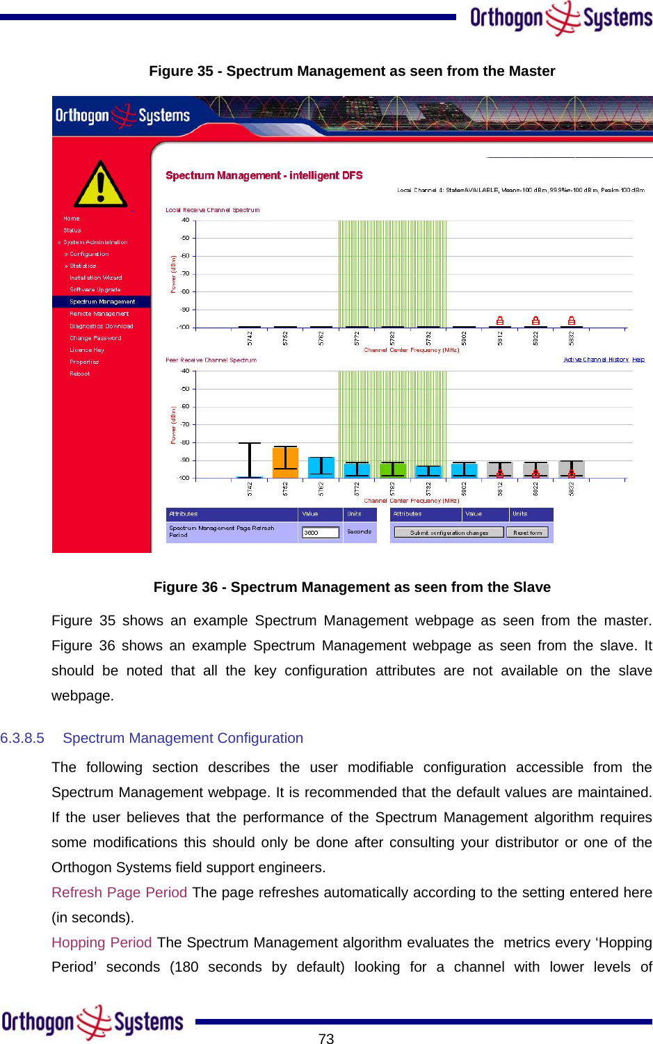
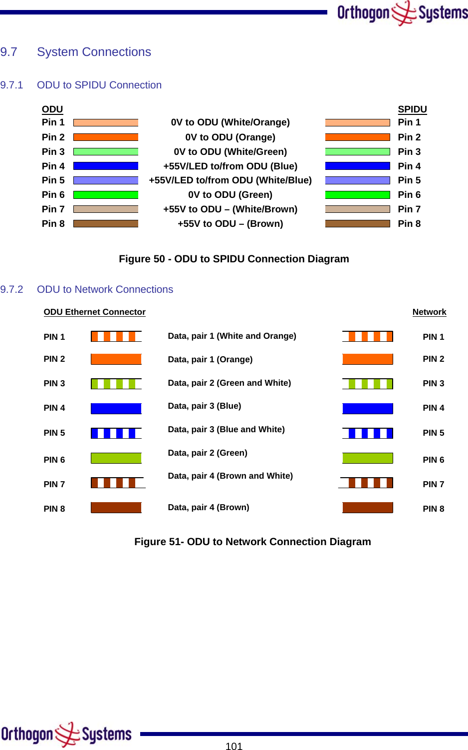
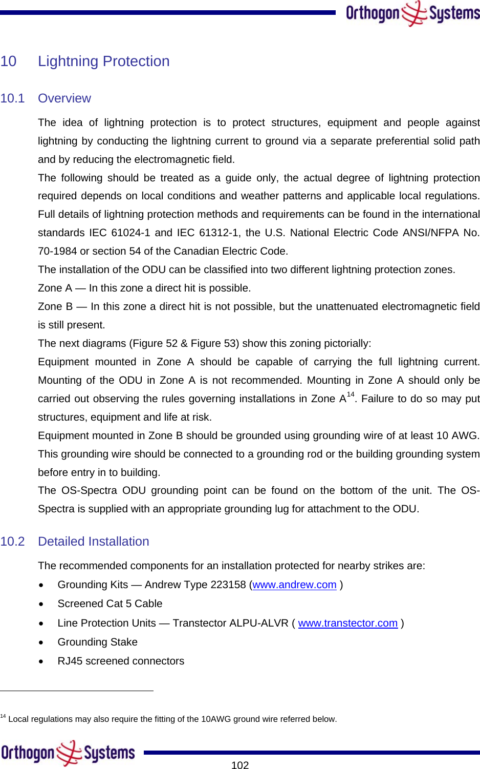
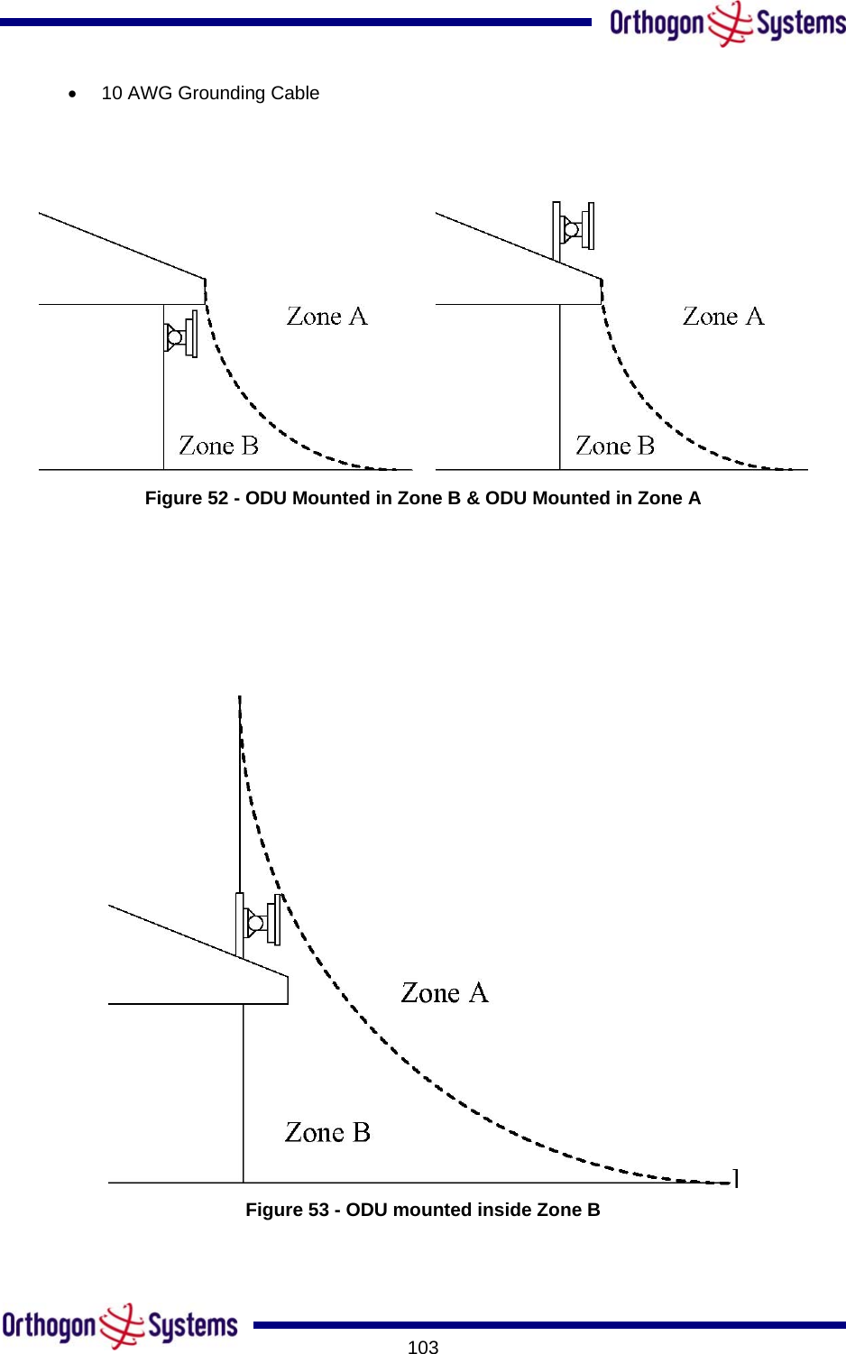
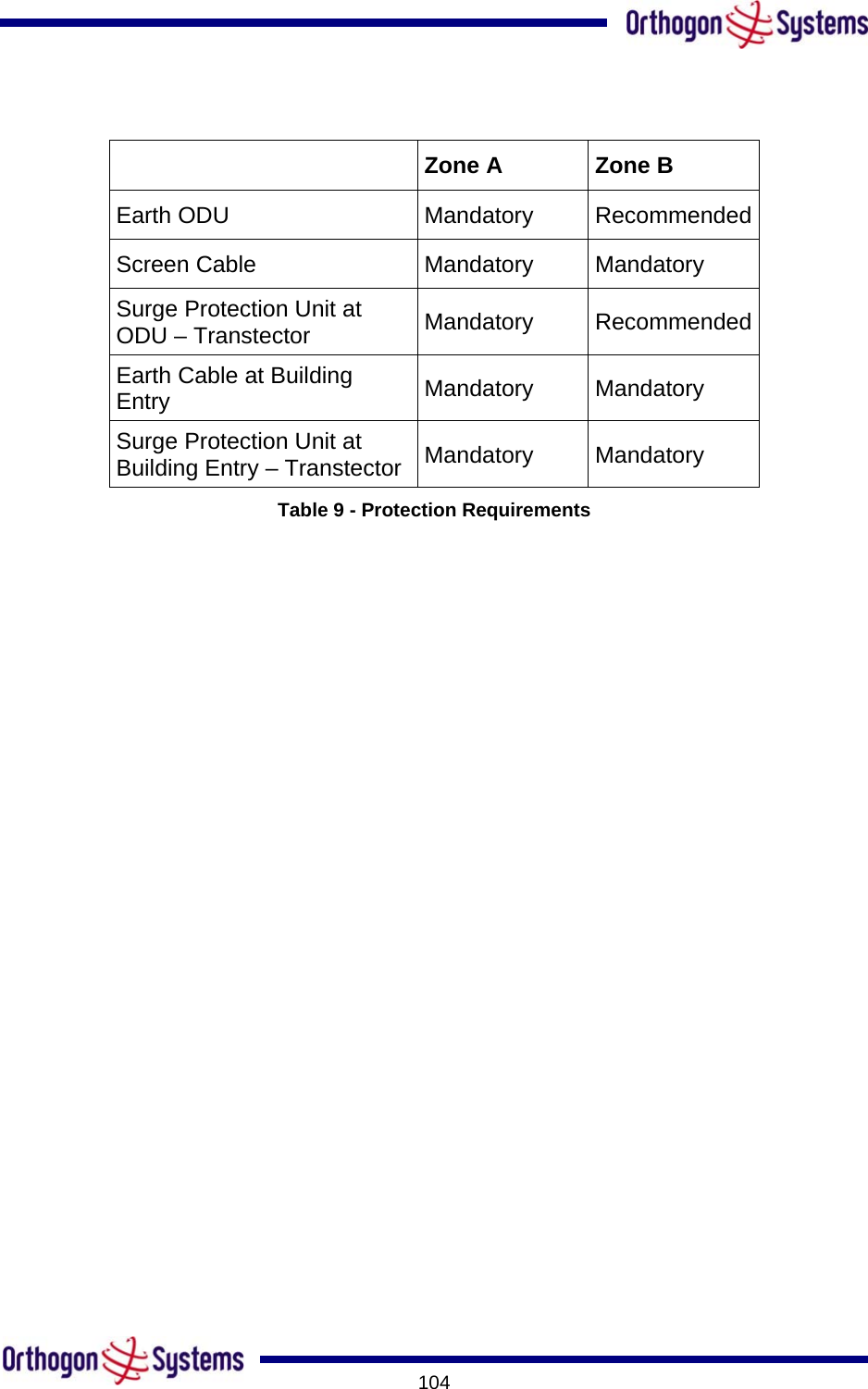
Cambium Networks 58100 Wireless Ethernet Bridge User Manual OS Gemini 5825
Cambium Networks Limited Wireless Ethernet Bridge OS Gemini 5825
UserManual.wiki
>
Cambium Networks
>
58100 User Manual
>
Users Manual
Contents
1.
Users Manual
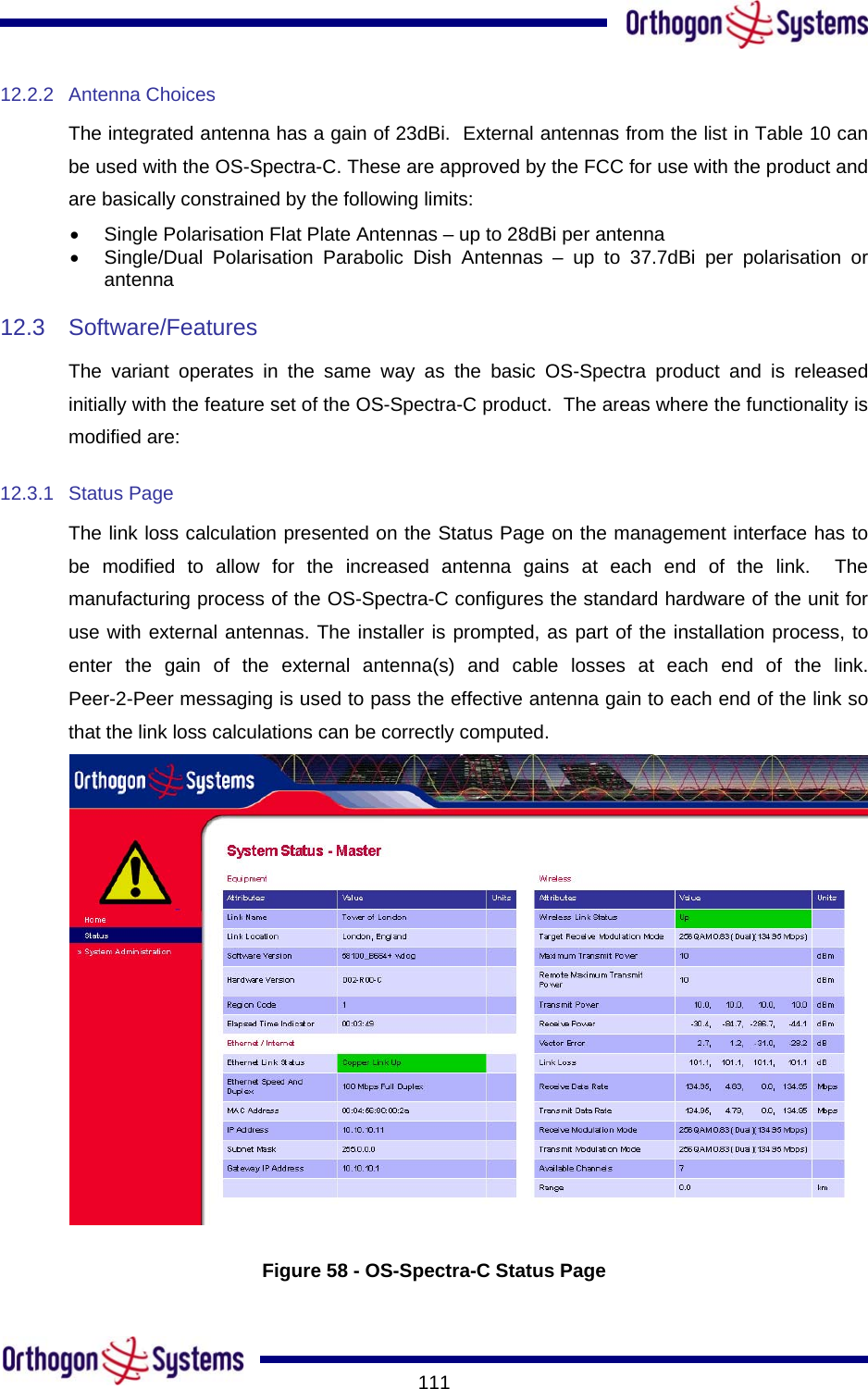
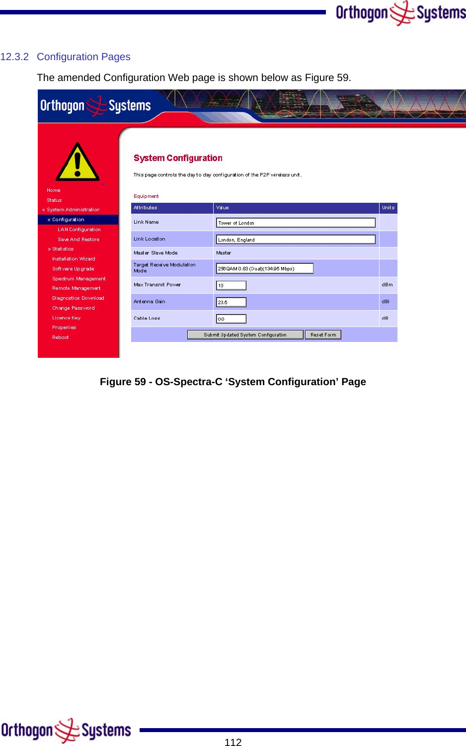
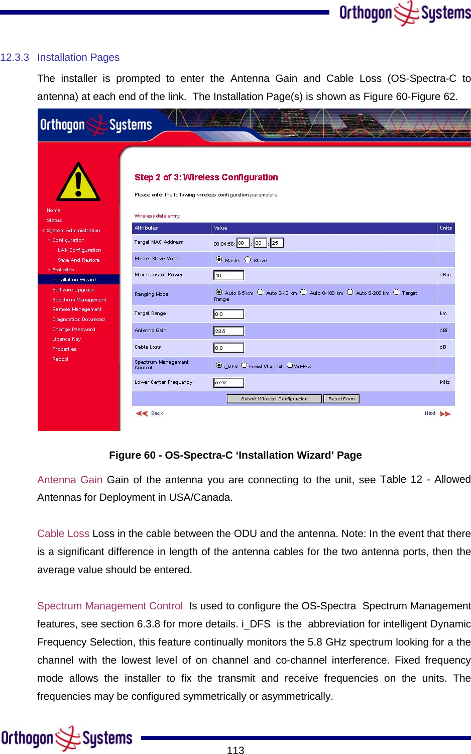
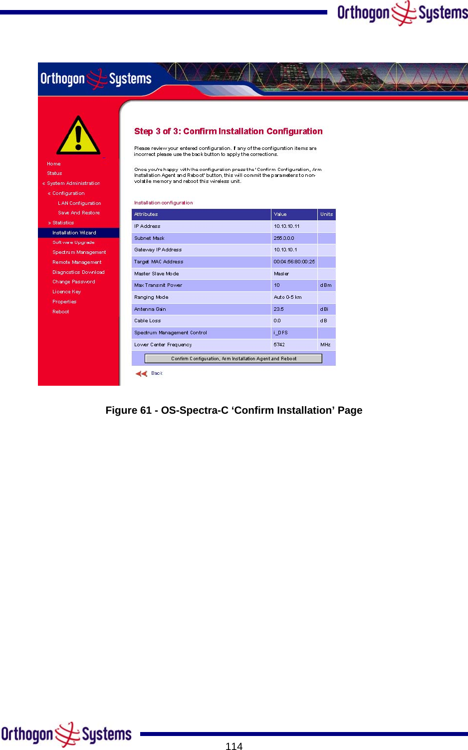
2.
User Guide Part 1
3.
User Guide Part 2
Users Manual
Navigation menu
Upload a User Manual
Namespaces
Wiki Guide
HTML
PDF
Info
Views
User Manual
Discussion / Help
Navigation