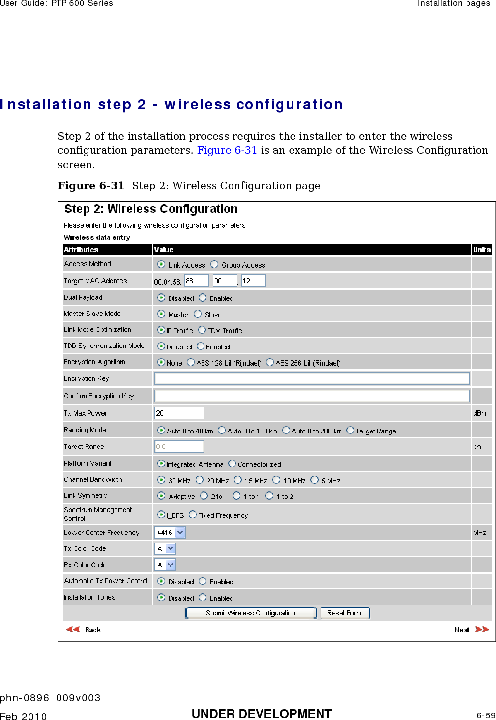
Cambium Networks 58100 Wireless Ethernet Bridge User Manual PTP 600 Series
Cambium Networks Limited Wireless Ethernet Bridge PTP 600 Series
UserManual.wiki
>
Cambium Networks
>
58100 User Manual
>
User Guide Part 2
Contents
1.
Users Manual
2.
User Guide Part 1
3.
User Guide Part 2
User Guide Part 2
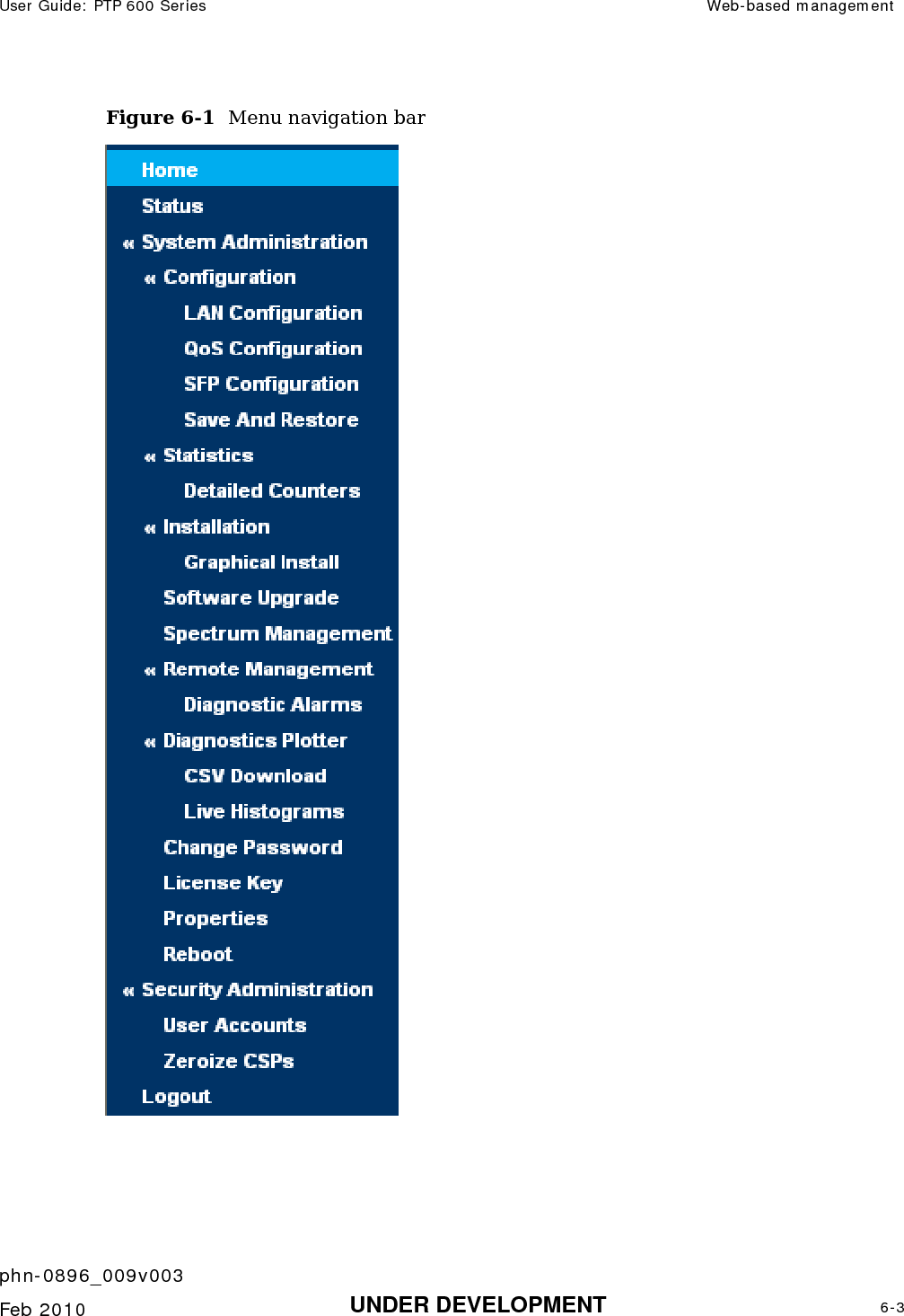
Navigation menu
Upload a User Manual
Namespaces
Wiki Guide
HTML
PDF
Info
Views
User Manual
Discussion / Help
Navigation


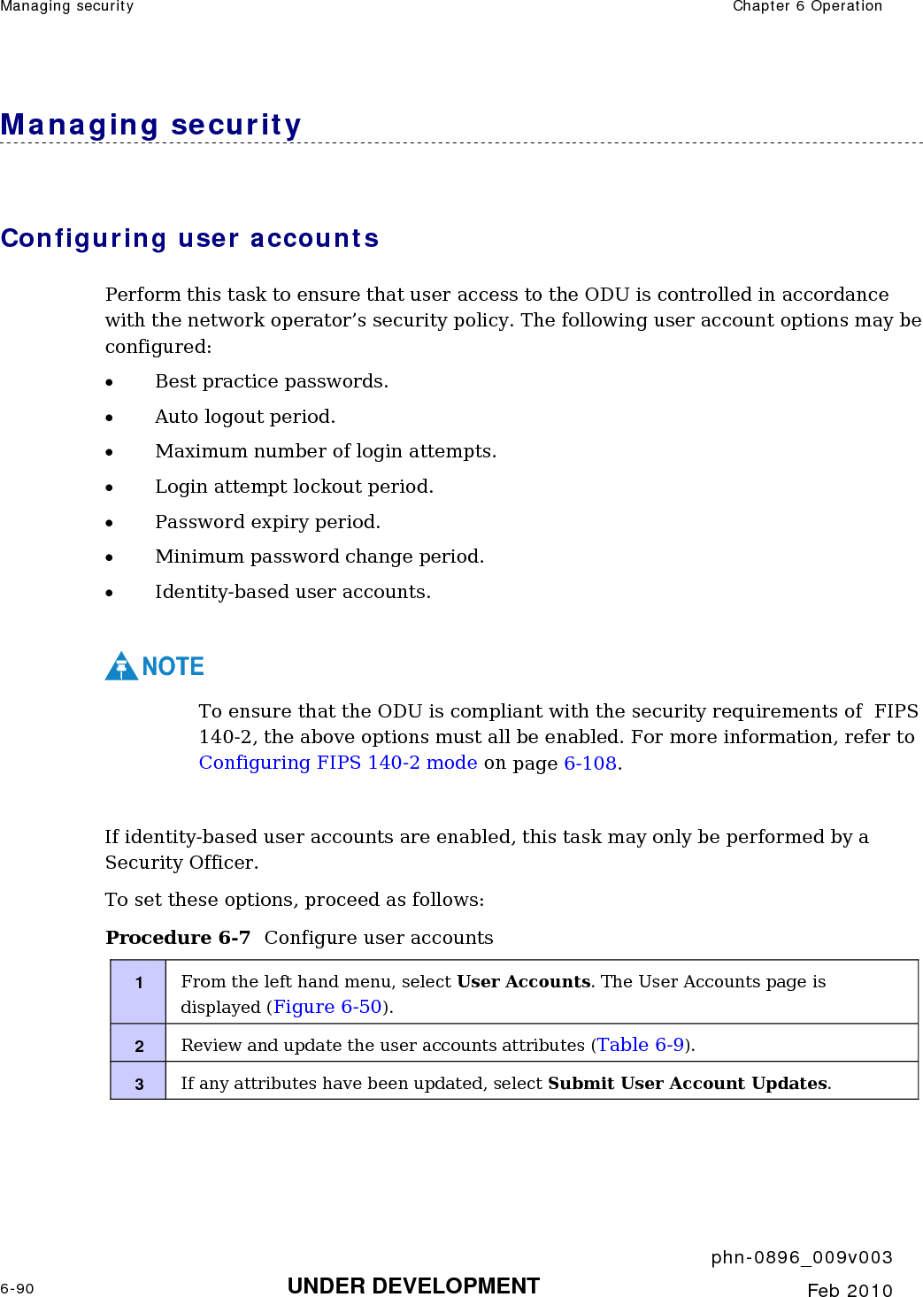
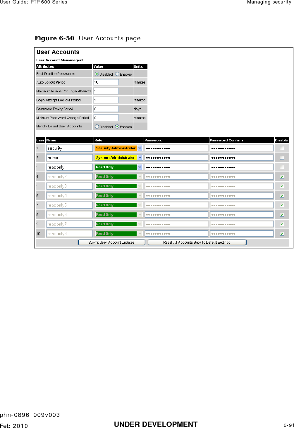
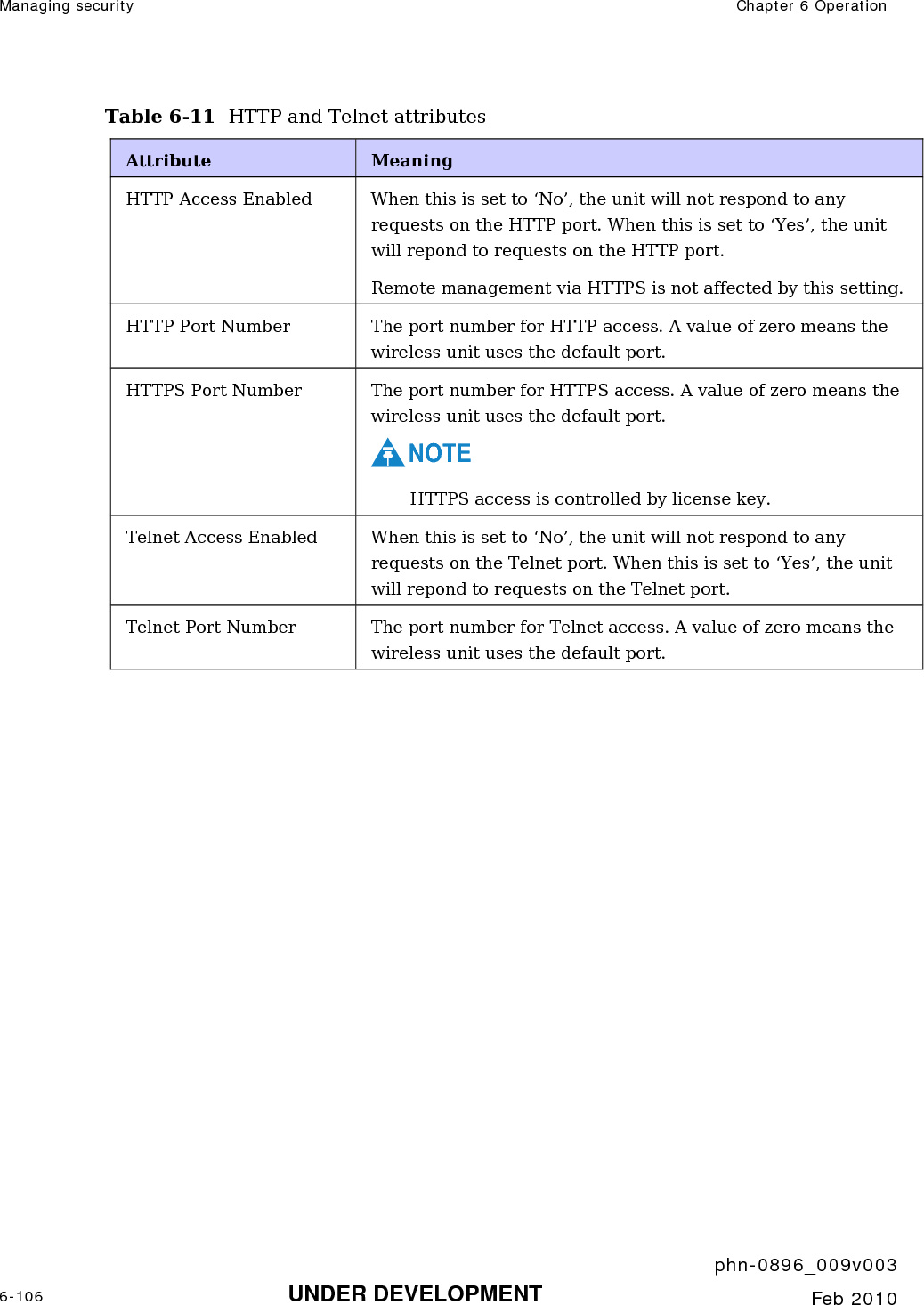
![Managing security Chapter 6 Operation phn-0896_009v003 6-92 UNDER DEVELOPMENT Feb 2010 Table 6-9 User accounts attributes Attribute Meaning Best Practice Passwords Disable or enable best practice password rules. When this is enabled, the following rules are applied to all passwords: Passwords are case sensitive. Password must contain at least eight characters. Passwords must contain at least: • One uppercase letter. • One lowercase letter. • One numeral. • One special character: !\"#$%&'()*+,-./:;<=>?@[\]^_`{|}~ Auto Logout Period The time without user activity that elapses before a user is automatically logged out (minutes). Maximum Number of Login Attempts The maximum number of login attempts (with incorrect password) that are allowed before a user is locked out. Login Attempt Lockout Period The time that elapses before a locked out user is allowed to log in again (minutes). Password Expiry Period The time that elapses before a password expires (days). When a password has expired, the user is forced to change it. Minimum Password Change Period The minimum time that elapses before a user is allowed to change a password (minutes). Identity Based User Accounts Enable or disable identity-based user accounts. When this is disabled, access to the web interface is controlled by a single system administration password, and the user account data entry table is disabled. When this is enabled, the user account data entry table is enabled. For more information, refer to Creating or updating identity-based users on page 6-93.](https://usermanual.wiki/Cambium-Networks/58100.User-Guide-Part-2/User-Guide-1237758-Page-189.png)
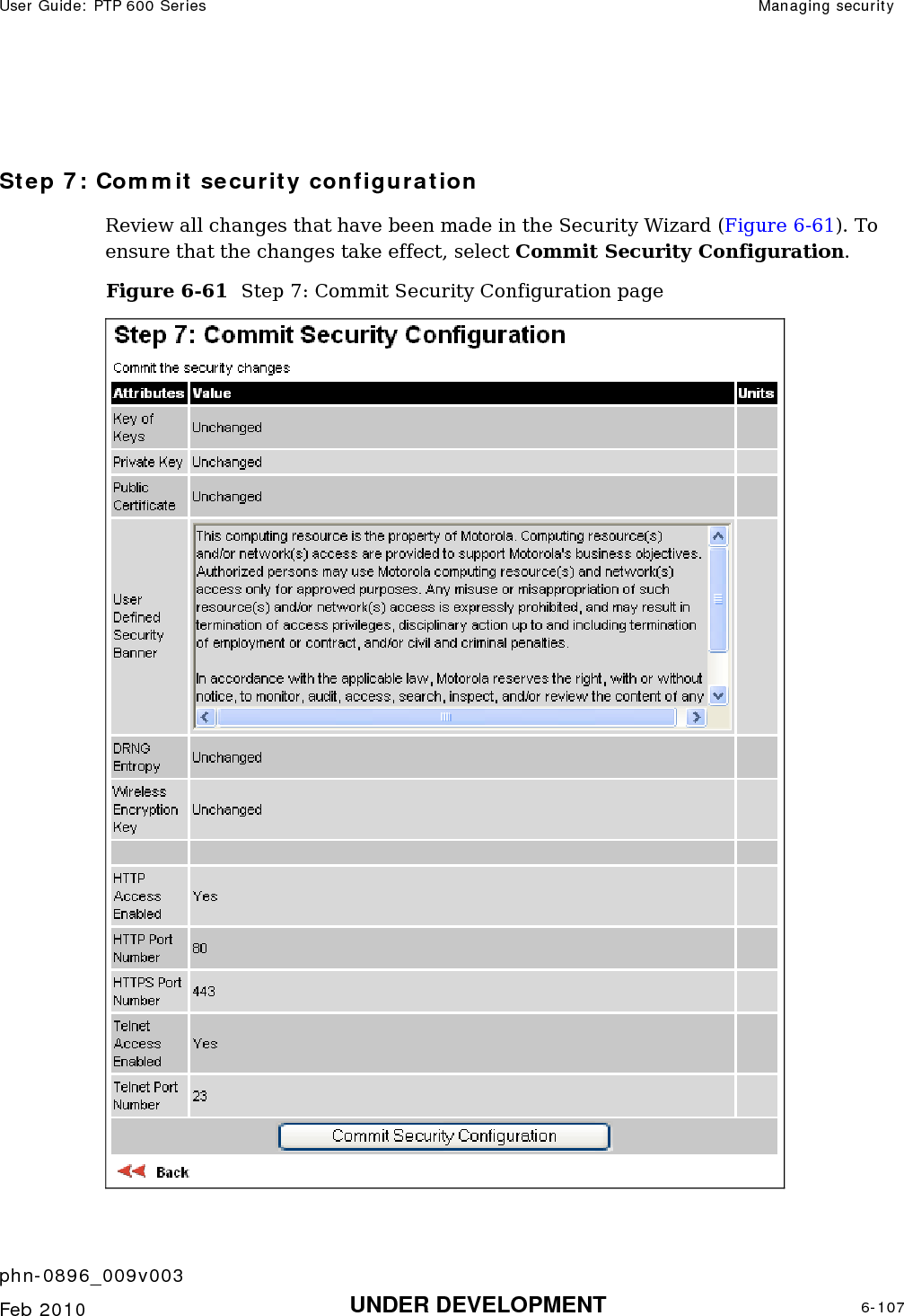


![User Guide: PTP 600 Series Regulatory issues with connectorized units phn-0896_009v003 Feb 2010 UNDER DEVELOPMENT 8-11 The Set_Max_Transmit_Power parameter As the actual maximum transmit power can only be adjusted in 1 dB steps, then the installer or operator must configure the PTP 600 to have a Set_Max_Transmit_Power parameter as calculated below: Set_Max_Transmit_Power = [Max_Transmit_Power] rounded down to nearest lower dB step In order to simplify matters, the settings to be used for regions with the EIRP limits in Table 8-1 (assuming short feeder cables) are shown in Table 8-2. NOTE Table 8-2 has been calculated on the basis of 0.5 dB cable loss and the highest gain antennas per size of which we are aware. At these operating frequencies, feeder losses even with short cables are unlikely ever to be below 0.5 dB for practical installations and cable diameters. Table 8-2 Setting maximum transmit power to meet general EIRP limits Set_Max_Transmit_Power parameter setting (dBm) Antenna size Maximum available antenna gain (dBi) Operating bandwidth (MHz) 5.4 GHz 5.8 GHz 5 -6 0 10 -3 3 15 -2 4 2ft dish 29.4 30 1 7 5 Not allowed -2 10 -5 1 15 -3 3 2.5ft dish 31.2 30 0 6 5 Not allowed -4 10 -7 -1 15 -5 0 3ft dish 33.4 30 -2 3](https://usermanual.wiki/Cambium-Networks/58100.User-Guide-Part-2/User-Guide-1237758-Page-268.png)