Cambium Networks 58100 Wireless Ethernet Bridge User Manual PTP 600 Series
Cambium Networks Limited Wireless Ethernet Bridge PTP 600 Series
Contents
- 1. Users Manual
- 2. User Guide Part 1
- 3. User Guide Part 2
User Guide Part 2

PTP 59600 reference information Chapter 4 Reference information
phn-0896_009v003
4-90 UNDER DEVELOPMENT Feb 2010
PTP 59600 reference information
This section contains reference information that is specific to the PTP 59600 frequency
variant.
PTP 59600 examples of regulatory limits
Table 4-57 shows how the regulatory limits currently apply in specific countries.
Operators should note that regulations are subject to change.
Table 4-57 PTP 59600 examples of regulatory limits
Region Examples of Regulatory Limits at 5.9 GHz
Russia Operation of this product is only allowed with a License Key for Region 16
(no power limit)
India
Operation of this product is only allowed with a License Key for Regions 17
or 19 (36 dBm or 4W EIRP at 30 MHz, 15 MHz and 10 MHz; and 33 dBm or
2 W EIRP at 5 MHz channel bandwidth).

User Guide: PTP 600 Series PTP 59600 reference information
phn-0896_009v003
Feb 2010 UNDER DEVELOPMENT 4-91
PTP 59600 licenses and region codes
PTP 59600 units may be operated in any of the regions listed in Table 4-58. When
shipped, PTP 59600 units are configured with a license key for region code 16. An
alternative license key is provided in the
PTP 600 Installation Guide
for region code
17. For any other permitted region, obtain a new license key from the reseller or
distributor.
Table 4-58 PTP 59600 licenses and region codes
Region
code
License /
Regulation Frequencies
DFS
Channel
Bandwidth Max Power
15 Unrestricted 5825 - 5925
MHz
5, 10, 15, 30
MHz
25 dBm
16 Russia 5825 - 5925
MHz
5, 10, 15, 30
MHz
25 dBm
10, 15, 30
MHz
36 dBm
EIRP
17
India
5875 - 5925
MHz
5 MHz 33 dBm
EIRP
10, 15, 30
MHz
36 dBm
EIRP
19 India 5825 - 5875
MHz
5 MHz 33 dBm
EIRP
NOTE
The 5.8 GHz license for India is addressed using both PTP 58600 and PTP
59600 frequency variants.

PTP 59600 reference information Chapter 4 Reference information
phn-0896_009v003
4-92 UNDER DEVELOPMENT Feb 2010
PTP 59600 regulatory compliance
Russia
This system has been tested for type approval in Russia of fixed link equipment under
the heading of BPD TZS 12.
Сертификат соответствия Срок действия
ОС-1-РД-0241 с 28 октября 2008 г.
PTP 59600 radio system specifications
Table 4-59 contains radio system specifications for the PTP 59600.
Table 4-59 PTP 59600 RF specifications
Radio Technology Specification
RF Band 5.825-5.925GHz
Channel Selection
By dynamic frequency control and manual intervention
Automatic detection on start-up and continual adaptation
to avoid interference.
Dynamic Frequency Control Initial capture 10-15 sec. Out of service on interference
100 ms.
Channel size 5, 10, 15 and 30 MHz
Manual Power Control
Maximum power can be controlled lower than the power
limits shown above in order to control interference to
other users of the band.
Receiver Noise Figure Typically 6 dB
Antenna Type Integrated flat plate antenna
Antenna Gain 23 dBi typical
Antenna Beamwidth 8 Degrees

User Guide: PTP 600 Series PTP 59600 reference information
phn-0896_009v003
Feb 2010 UNDER DEVELOPMENT 4-93
Radio Technology Specification
Max Path Loss (5 MHz
Channel) 166 dB
Duplex Scheme Symmetric fixed, asymmetric fixed or adaptive TDD
Range
125 miles (200km) optical line-of-sight
6 miles (10km) non-line-of-sight
Over-the-Air Encryption Proprietary scrambling mechanism.
Weather Sensitivity
Sensitivity at higher modes may be reduced during high
winds through trees due to Adaptive Modulation
Threshold changes
Error Correction FEC
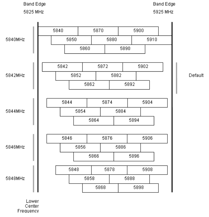
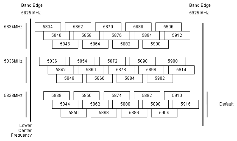
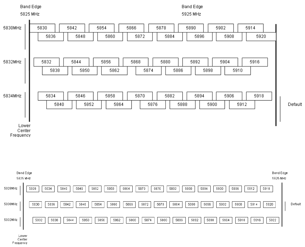
PTP 59600 available spectrum settings
The available spectrum settings for the PTP 59600 are illustrated in this section.
Adjustment of the lower centre frequency allows the operator to slide the available
frequency settings up and down the 5.9 GHz band in steps of 2 MHz.
In the 30 MHz channel bandwidth (Figure 4-26) the PTP 59600 variant operates on a
10 MHz channel raster. In the 15 MHz (Figure 4-27), 10 MHz (Figure 4-28) and 5 MHz
(Figure 4-29) channel bandwidths, the PTP 59600 variant operates on a 6 MHz
channel raster. The channel raster is set to even centre frequencies.
NOTE
These tables contain data for one typical region code. The specified channel
centre frequencies may not be available in other region codes.
The PTP 59600 product variant does not apply any band edge power reduction.
PTP 59600 reference information Chapter 4 Reference information
phn-0896_009v003
4-94 UNDER DEVELOPMENT Feb 2010
Figure 4-26 PTP 59600 available spectrum in 30 MHz channel bandwidth
User Guide: PTP 600 Series PTP 59600 reference information
phn-0896_009v003
Feb 2010 UNDER DEVELOPMENT 4-95
Figure 4-27 PTP 59600 available spectrum in 15 MHz channel bandwidth
PTP 59600 reference information Chapter 4 Reference information
phn-0896_009v003
4-96 UNDER DEVELOPMENT Feb 2010
Figure 4-28 PTP 59600 available spectrum in 10 MHz channel bandwidth
Figure 4-29 PTP 59600 available spectrum in 5 MHz channel bandwidth

User Guide: PTP 600 Series PTP 59600 reference information
phn-0896_009v003
Feb 2010 UNDER DEVELOPMENT 4-97
PTP 59600 system threshold, output power and link loss
PTP 59600 system threshold figures are given in Table 4-60 (IP mode) and Table 4-61
(TDM mode). These figures assume that antenna gain is 23 dBi.
Table 4-60 PTP 59600 - IP mode - threshold, power and loss per modulation mode
Threshold Value (dBm)
Output
Power
(dBm)
Maximum Link Loss (dB)
Channel
Bandwidth
Modulation
Mode
5
MHz
10
MHz
15
MHz
30
MH
z
All
Bands
5
MHz
10
MHz
15
MHz
30
MHz
BPSK 0.63 single -97.1 -94.1 -92.0 -88.7 +25.0 168.1 165.1 163.0 159.7
QPSK 0.63 single -90.7 -88.1 -87.1 -82.5 +24.0 160.7 158.1 157.1 152.5
QPSK 0.87 single -87.2 -84.4 -83.5 -79.3 +23.0 156.2 153.4 152.5 148.3
16QAM 0.63 single -85.0 -81.9 -81.2 -77.1 +22.0 153.0 149.9 149.2 145.1
16QAM 0.63 dual -81.9 -78.8 -77.5 -73.5 +22.0 149.9 146.8 145.5 141.5
16QAM 0.87 single -80.9 -78.0 -76.7 -72.9 +20.0 146.9 143.9 142.7 138.9
16QAM 0.87 dual -76.5 -73.9 -73.2 -70.0 +20.0 142.5 139.9 139.2 136.0
64QAM 0.75 single -77.0 -74.6 -73.6 -70.3 +18.0 141.0 138.6 137.6 134.3
64QAM 0.75 dual -73.1 -71.0 -70.4 -67.5 +18.0 137.1 135.0 134.4 131.5
64QAM 0.92 single -72.1 -71.0 -68.9 -65.7 +18.0 136.1 135.0 132.9 129.7
64 QAM 0.92 dual -70.2 -67.2 -66.1 -62.1 +18.0 134.2 131.1 130.1 126.1
256QAM 0.81 single N/A N/A N/A -63.9 +18.0 N/A N/A N/A 127.9
256QAM 0.81 dual N/A N/A N/A -59.9 +18.0 N/A N/A N/A 123.9

PTP 59600 reference information Chapter 4 Reference information
phn-0896_009v003
4-98 UNDER DEVELOPMENT Feb 2010
Table 4-61 PTP 59600 - TDM mode - threshold, power and loss per modulation mode
Threshold Value (dBm)
Output
Power
(dBm)
Maximum Link Loss (dB)
Channel
Bandwidth
Modulation
Mode
5
MHz
10
MHz
15
MHz
30
MH
z
All
Bands
5
MHz
10
MHz
15
MHz
30
MHz
BPSK 0.63 single -97.1 -94.1 -92.0 -88.7 +25.0 168.1 165.1 163.0 159.7
QPSK 0.63 single -88.5 -86.1 -84.4 -79.4 +24.0 158.5 156.1 154.4 149.4
QPSK 0.87 single -84.6 -81.9 -80.1 -76.0 +23.0 153.6 150.9 149.1 145.0
16QAM 0.63 single -82.5 -79.6 -77.8 -73.7 +22.0 150.4 147.6 145.8 141.7
16QAM 0.63 dual -78.8 -76.0 -74.1 -70.4 +22.0 146.8 144.0 142.1 138.4
16QAM 0.87 single -78.3 -75.1 -73.7 -70.2 +20.0 144.3 141.1 139.7 136.2
16QAM 0.87 dual -74.2 -71.6 -70.2 -66.9 +20.0 140.2 137.6 134.2 132.9
64QAM 0.75 single -74.7 -71.4 -70.2 -67.3 +18.0 138.7 135.4 134.2 131.3
64QAM 0.75 dual -70.9 -68.3 -66.8 -63.6 +18.0 134.8 132.2 130.8 127.6
64QAM 0.92 single -71.2 -68.1 -67.0 -63.3 +18.0 135.2 132.0 131.0 127.3
64 QAM 0.92 dual -66.7 -64.2 -62.7 -58.7 +18.0 130.7 128.2 126.7 122.7
256QAM 0.81 single N/A N/A N/A -63.3 +18.0 N/A N/A N/A 127.3
256QAM 0.81 dual N/A N/A N/A -58.7 +18.0 N/A N/A N/A 122.7

User Guide: PTP 600 Series Data rate calculations
phn-0896_009v003
Feb 2010 UNDER DEVELOPMENT 4-99
Data rate calculations
This section provides instructions, tables and graphs to allow calculation of the data
rate capacity that can be provided by alternative PTP 600 configurations.
The following topics are described in this section:
• Data rate defined on page 4-99
• Calculation procedure and example on page 4-99
• Data throughput capacity on page 4-102
• Range adjustment curves on page 4-113
Data rate defined
The data rate capacity of a PTP link is defined as the maximum end-to-end Ethernet
throughput (including Ethernet headers) that it can support. It is assumed that
Ethernet frames are 1500 octet. Data rate capacity is determined by the following
factors:
• Product variant (PTP 600 Full or Lite)
• Link Symmetry
• Link Mode Optimization (IP or TDM)
• Modulation Mode
• Channel Bandwidth
• Link Range
Calculation procedure and example
Procedure
To calculate the data rate capacity of a PTP 600 link, perform Procedure 4-1.

Data rate calculations Chapter 4 Reference information
phn-0896_009v003
4-100 UNDER DEVELOPMENT Feb 2010
Procedure 4-1 Calculating data rate capacity
1 Use the tables in Data throughput capacity on page 4-102 to look up the
data throughput capacity rates (Tx, Rx and Both) for the required
combination of:
• Link Symmetry
• Link Mode Optimization
• Modulation Mode
• Channel Bandwidth
2 The tables contain data rates for PTP 600 Full only. If the ODUs are PTP
600 Lite, divide the data rates by 2.
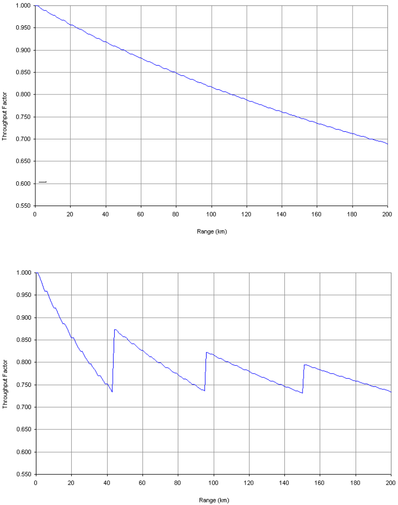
3 The tables contain data rates for links of zero range. Use the curves in
Range adjustment curves on page 4-113 to look up the Throughput
Factor that must be applied to adjust the data rates for the actual range of
the link.
4 Multiply the data rates by the Throughput Factor to give the throughput
capacity of the link.
NOTE
There is a small difference between the rates for IP and TDM because there
is fragmentation in TDM (for low priority traffic) which causes the
throughput to be reduced buy approximately 1% compared to the IP mode.

User Guide: PTP 600 Series Data rate calculations
phn-0896_009v003
Feb 2010 UNDER DEVELOPMENT 4-101
Example
Suppose that the link characteristics are:
• Product variant = PTP 600 Lite
• Link Symmetry = 1:1
• Link Mode Optimization = TDM
• Modulation Mode = 64QAM 0.92 Dual
• Channel Bandwidth = 10 MHz
• Link Range = 60 km
The calculation procedure for this example is described in Procedure 4-2.
Procedure 4-2 Example of data rate capacity calculation
1 Use Table 4-63 to look up the data throughput capacity rates:
• Tx = 41.41 Mbits/s
• Rx = 41.41 Mbits/s
• Both = 82.81 Mbits/s
2 Divide these rates by 2 to give PTP 600 Lite rates:
• Tx = 20.70 Mbits/s
• Rx = 20.70 Mbits/s
• Both = 41.40 Mbits/s
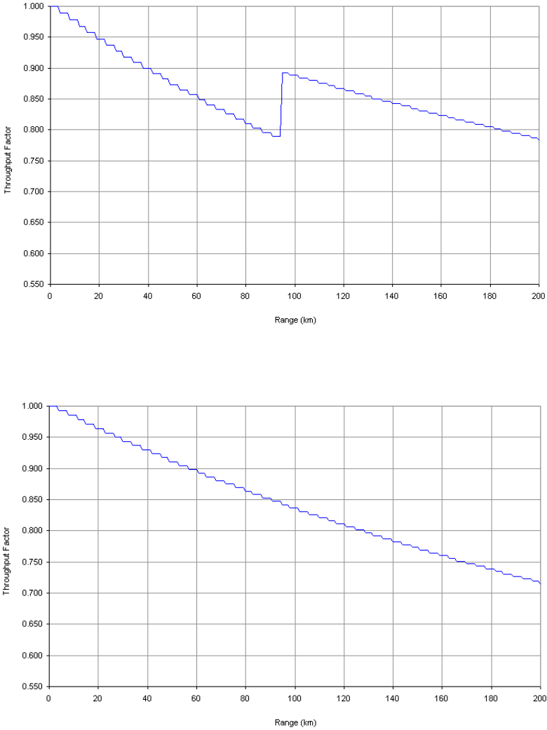
3 Use Figure 4-38 to look up the Throughput Factor for 1:1, TDM and Link
Range 60 km. The factor is 0.86.
4 Multiply the rates from Step 2 by the Throughput Factor from Step 3 to
give the throughput capacity of the link:
• Tx = 17.80 Mbits/s
• Rx = 17.80 Mbits/s
• Both = 35.60 Mbits/s

Data rate calculations Chapter 4 Reference information
phn-0896_009v003
4-102 UNDER DEVELOPMENT Feb 2010
Data throughput capacity
Table 4-62, Table 4-63, Table 4-64, Table 4-65 and Table 4-66 show the data
throughput rates (Mbits/s) that are achieved when two PTP 600 Full ODUs are linked
and the link distance (range) is 0 km. Use the curves in Range adjustment curves on
page 4-113 to adjust these figures to allow for link range.
NOTE
When using these tables, be aware of the factors that affect data throughput,
as listed below.
Data throughput capacity is restricted by the following factors:
• PTP 600 Lite data rates are half the PTP 600 Full rates given in this section.
• Modulation Mode “256QAM 0.81 dual” is not available in all product variants and
channel bandwidths.
• Throughput for Link Symmetry 2:1 is the same as that for 1:2, but the Tx and Rx
data rates are swapped.
• The data rates for Adaptive symmetry apply to the most asymmetric case where
the link has significant offered traffic in one direction only. The data rates for
Adaptive symmetry with bidirectional offered traffic are the same as those for
Link Symmetry = 1:1 with Link Optimization = IP.

User Guide: PTP 600 Series Data rate calculations
phn-0896_009v003
Feb 2010 UNDER DEVELOPMENT 4-103
Table 4-62 Throughput for PTP 600 Full, link symmetry 1:1, link optimization IP
30 MHz 20 MHz 15 MHz
Modulation Mode
Tx Rx Both Tx Rx Both Tx Rx Both
256QAM 0.81 dual 150.01 150.01
300.02
100.06
100.06
200.12 75.37 75.37
150.74
64QAM 0.92 dual 126.39 126.39
252.78
84.30 84.30 168.61 63.50 63.50
127.01
64QAM 0.75 dual 103.28 103.28
206.57
68.89 68.89 137.78 51.89 51.89
103.79
16QAM 0.87 dual 80.35 80.35 160.70
53.60 53.60 107.19 40.37 40.37
80.74
16QAM 0.63 dual 57.76 57.76 115.52
38.53 38.53 77.06 29.02 29.02
58.04
256QAM 0.81
single 75.00 75.00 150.01
50.03 50.03 100.06
37.69 37.69
75.37
64QAM 0.92 single 63.19 63.19 126.39
42.15 42.15 84.30 31.75 31.75
63.50
64QAM 0.75 single 51.64 51.64 103.28
34.45 34.45 68.89 25.95 25.95
51.89
16QAM 0.87 single 40.17 40.17 80.35 26.80 26.80 53.59 20.18 20.18
40.37
16QAM 0.63 single 28.88 28.88 57.76 19.26 19.26 38.53 14.51 14.51
29.02
QPSK 0.87 single 20.09 20.09 40.17 13.40 13.40 26.79 10.09 10.09
20.18
QPSK 0.63 single 14.44 14.44 28.88 9.63 9.63 19.26 7.25 7.25 14.51
BPSK 0.63 single 7.22 7.22 14.44 4.81 4.81 9.63 3.63 3.63 7.25
At zero range. All rates are in Mbit/s.

Data rate calculations Chapter 4 Reference information
phn-0896_009v003
4-104 UNDER DEVELOPMENT Feb 2010
Table 4-62 Throughput for PTP 600 Full, link symmetry 1:1, link optimization IP
(continued)
10 MHz 5 MHz
Modulation Mode
Tx Rx Both Tx Rx Both
256QAM 0.81 dual 50.11
50.11
100.21
24.22
24.22 48.43
64QAM 0.92 dual 42.22
42.22
84.43 20.40
20.40 40.80
64QAM 0.75 dual 34.50
34.50
69.00 16.67
16.67 33.34
16QAM 0.87 dual 26.84
26.84
53.68 12.97
12.97 25.94
16QAM 0.63 dual 19.29
19.29
38.59 9.32 9.32 18.65
256QAM 0.81
single 25.05
25.05
50.11 12.11
12.11 24.21
64QAM 0.92 single 21.11
21.11
42.21 10.20
10.20 20.40
64QAM 0.75 single 17.25
17.25
34.50 8.34 8.34 16.67
16QAM 0.87 single 13.42
13.42
26.84 6.48 6.48 12.97
16QAM 0.63 single 9.65 9.65 19.29 4.66 4.66 9.32
QPSK 0.87 single 6.71 6.71 13.42 3.24 3.24 6.48
QPSK 0.63 single 4.82 4.82 9.64 2.33 2.33 4.66
BPSK 0.63 single 2.41 2.41 4.82 1.16 1.16 2.33

User Guide: PTP 600 Series Data rate calculations
phn-0896_009v003
Feb 2010 UNDER DEVELOPMENT 4-105
Table 4-63 Throughput for PTP 600 Full, link symmetry 1:1, link optimization TDM
30 MHz 20 MHz 15 MHz
Modulation Mode
Tx Rx Both Tx Rx Both Tx Rx Both
256QAM 0.81 dual 140.87 140.87
281.74
96.01
96.01
192.02
72.92 72.92
145.83
64QAM 0.92 dual 118.69 118.69
237.38
80.89
80.89
161.78
61.43 61.43
122.87
64QAM 0.75 dual 96.99 96.99 193.98
66.10
66.10
132.21
50.20 50.20
100.41
16QAM 0.87 dual 75.45 75.45 150.91
51.43
51.43
102.85
39.06 39.06
78.11
16QAM 0.63 dual 54.24 54.24 108.48
36.97
36.97
73.94 28.08 28.08
56.15
256QAM 0.81
single 70.43 70.43 140.87
48.00
48.00
96.01
36.46 36.46
72.91
64QAM 0.92 single 59.34 59.34 118.69
40.44
40.44
80.89 30.72 30.72
61.43
64QAM 0.75 single 48.49 48.49 96.99 33.05
33.05
66.10 25.10 25.10
50.20
16QAM 0.87 single 37.73 37.73 75.45 25.71
25.71
51.42 19.53 19.53
39.05
16QAM 0.63 single 27.12 27.12 54.24 18.48
18.48
36.97 14.04 14.04
28.07
QPSK 0.87 single 18.86 18.86 37.72 12.85
12.85
25.71 9.76 9.76 19.52
QPSK 0.63 single 13.56 13.56 27.12 9.24 9.24 18.48 7.02 7.02 14.03
BPSK 0.63 single 6.78 6.78 13.56 4.62 4.62 9.24 3.51 3.51 7.02
At zero range. All rates are in Mbit/s.

Data rate calculations Chapter 4 Reference information
phn-0896_009v003
4-106 UNDER DEVELOPMENT Feb 2010
Table 4-63 Throughput for PTP 600 Full, link symmetry 1:1, link optimization TDM
(continued)
10 MHz 5 MHz
Modulation Mode
Tx Rx Both Tx Rx Both
256QAM 0.81 dual 49.14 49.14 98.29 24.22 24.22 48.43
64QAM 0.92 dual 41.41 41.41 82.81 20.40 20.40 40.80
64QAM 0.75 dual 33.84 33.84 67.67 16.67 16.67 33.34
16QAM 0.87 dual 26.32 26.32 52.64 12.97 12.97 25.94
16QAM 0.63 dual 18.92 18.92 37.84 9.32 9.32 18.65
256QAM 0.81
single 24.57 24.57 49.14 12.11 12.11 24.21
64QAM 0.92 single 20.70 20.70 41.40 10.20 10.20 20.40
64QAM 0.75 single 16.92 16.92 33.83 8.34 8.34 16.67
16QAM 0.87 single 13.16 13.16 26.32 6.48 6.48 12.97
16QAM 0.63 single 9.46 9.46 18.92 4.66 4.66 9.32
QPSK 0.87 single 6.58 6.58 13.16 3.24 3.24 6.48
QPSK 0.63 single 4.73 4.73 9.46 2.33 2.33 4.66
BPSK 0.63 single 2.36 2.36 4.73 1.16 1.16 2.33

User Guide: PTP 600 Series Data rate calculations
phn-0896_009v003
Feb 2010 UNDER DEVELOPMENT 4-107
Table 4-64 Throughput for PTP 600 Full, link symmetry 2:1, link optimization = IP
30 MHz 20 MHz 15 MHz
Modulation Mode
Tx Rx Both Tx Rx Both Tx Rx Both
256QAM 0.81 dual 198.58 99.29
297.88
133.42
66.71
200.12
100.50 50.25
150.74
64QAM 0.92 dual 167.31 83.66
250.97
112.41
56.20
168.61
84.67 42.33
127.01
64QAM 0.75 dual 136.73 68.36
205.09
91.86 45.93
137.78
69.19 34.59
103.79
16QAM 0.87 dual 106.37 53.18
159.55
71.46 35.73
107.19
53.83 26.91
80.74
16QAM 0.63 dual 76.47 38.23
114.70
51.37 25.68
77.06 38.70 19.35
58.04
256QAM 0.81
single 99.29 49.64
148.94
66.71 33.35
100.06
50.25 25.12
75.37
64QAM 0.92 single 83.66 41.83
125.48
56.20 28.10
84.30 42.33 21.17
63.50
64QAM 0.75 single 68.36 34.18
102.54
45.93 22.96
68.89 34.59 17.30
51.89
16QAM 0.87 single 53.18 26.59
79.77 35.73 17.86
53.59 26.91 13.46
40.37
16QAM 0.63 single 38.23 19.11
57.35 25.68 12.84
38.53 19.35 9.67 29.02
QPSK 0.87 single 26.59 13.29
39.88 17.86 8.93 26.79 13.46 6.73 20.18
QPSK 0.63 single 19.11 9.56 28.67 12.84 6.42 19.26 9.67 4.84 14.51
BPSK 0.63 single 9.56 4.78 14.33 6.42 3.21 9.63 4.84 2.42 7.25
At zero range. All rates are in Mbit/s.

Data rate calculations Chapter 4 Reference information
phn-0896_009v003
4-108 UNDER DEVELOPMENT Feb 2010
Table 4-64 Throughput for PTP 600 Full, link symmetry 2:1, link optimization = IP
(continued)
10 MHz
Modulation Mode
Tx Rx Both
256QAM 0.81 dual 66.38
33.19
99.56
64QAM 0.92 dual 55.92
27.96
83.88
64QAM 0.75 dual 45.70
22.85
68.55
16QAM 0.87 dual 35.55
17.78
53.33
16QAM 0.63 dual 25.56
12.78
38.34
256QAM 0.81
single 33.19
16.59
49.78
64QAM 0.92 single 27.96
13.98
41.94
64QAM 0.75 single 22.85
11.42
34.27
16QAM 0.87 single 17.78
8.89 26.66
16QAM 0.63 single 12.78
6.39 19.17
QPSK 0.87 single 8.89 4.44 13.33
QPSK 0.63 single 6.39 3.19 9.58
BPSK 0.63 single 3.19 1.60 4.79
This combination is not available with Channel Bandwidth 5 MHz.

User Guide: PTP 600 Series Data rate calculations
phn-0896_009v003
Feb 2010 UNDER DEVELOPMENT 4-109
Table 4-65 Throughput for PTP 600 Full, link symmetry 2:1, link optimization = TDM
30 MHz 20 MHz 15 MHz
Modulation Mode
Tx Rx Both Tx Rx Both Tx Rx Both
256QAM 0.81 dual 193.06 96.53
289.58
130.66
65.33
195.99
98.83 49.42
148.25
64QAM 0.92 dual 162.66 81.33
243.98
110.08
55.04
165.13
83.27 41.63
124.90
64QAM 0.75 dual 132.92 66.46
199.38
89.96 44.98
134.94
68.05 34.02
102.07
16QAM 0.87 dual 103.41 51.70
155.11
69.98 34.99
104.98
52.94 26.47
79.40
16QAM 0.63 dual 74.34 37.17
111.50
50.31 25.15
75.46 38.05 19.03
57.08
256QAM 0.81
single 96.53 48.26
144.79
65.33 32.66
97.99
49.42 24.71
74.12
64QAM 0.92 single 81.33 40.66
121.99
55.04 27.52
82.56 41.63 20.82
62.45
64QAM 0.75 single 66.46 33.23
99.69 44.98 22.49
67.47 34.02 17.01
51.03
16QAM 0.87 single 51.70 25.85
77.55 34.99 17.49
52.49 26.47 13.23
39.70
16QAM 0.63 single 37.17 18.58
55.75 25.15 12.58
37.73 19.03 9.51 28.54
QPSK 0.87 single 25.85 12.92
38.77 17.49 8.75 26.24 13.23 6.62 19.85
QPSK 0.63 single 18.58 9.29 27.87 12.58 6.29 18.86 9.51 4.76 14.27
BPSK 0.63 single 9.29 4.64 13.93 6.29 3.14 9.43 4.76 2.38 7.13
At zero range. All rates are in Mbit/s.

Data rate calculations Chapter 4 Reference information
phn-0896_009v003
4-110 UNDER DEVELOPMENT Feb 2010
Table 4-65 Throughput for PTP 600 Full, link symmetry 2:1, link optimization
= TDM
(continued)
10 MHz
Modulation
Mode Tx Rx Both
256QAM 0.81 dual 66.38
33.19
99.56
64QAM 0.92 dual 55.92
27.96
83.88
64QAM 0.75 dual 45.70
22.85
68.55
16QAM 0.87 dual 35.55
17.78
53.33
16QAM 0.63 dual 25.56
12.78
38.34
256QAM 0.81
single 33.19
16.59
49.78
64QAM 0.92 single 27.96
13.98
41.94
64QAM 0.75 single 22.85
11.42
34.27
16QAM 0.87 single 17.78
8.89 26.66
16QAM 0.63 single 12.78
6.39 19.17
QPSK 0.87 single 8.89 4.44 13.33
QPSK 0.63 single 6.39 3.19 9.58
BPSK 0.63 single 3.19 1.60 4.79
This combination is not available with Channel Bandwidth 5 MHz.

User Guide: PTP 600 Series Data rate calculations
phn-0896_009v003
Feb 2010 UNDER DEVELOPMENT 4-111
Table 4-66 Throughput for PTP 600 Full, link symmetry Adaptive, link optimization =
IP
30 MHz 20 MHz 15 MHz
Modulation Mode
Tx Rx Both Tx Rx Both Tx Rx Both
256QAM 0.81 dual 236.95 59.23
296.18
148.53
49.51
198.03
112.12 37.37
149.49
64QAM 0.92 dual 199.63 49.91
249.54
125.14
41.71
166.85
94.46 31.49
125.95
64QAM 0.75 dual 163.14 40.78
203.92
102.26
34.09
136.35
77.19 25.73
102.92
16QAM 0.87 dual 126.91 31.73
158.64
79.55 26.52
106.07
60.05 20.02
80.07
16QAM 0.63 dual 91.24 22.81
114.04
57.19 19.06
76.25 43.17 14.39
57.56
256QAM 0.81
single 118.47 29.62
148.09
74.26 24.75
99.02
56.06 18.68
74.74
64QAM 0.92 single 99.82 24.95
124.77
62.57 20.85
83.42 47.23 15.74
62.97
64QAM 0.75 single 81.57 20.39
101.96
51.13 17.04
68.17 38.59 12.86
51.46
16QAM 0.87 single 63.46 15.86
79.32 39.78 13.26
53.03 30.02 10.01
40.03
16QAM 0.63 single 45.62 11.40
57.02 28.59 9.53 38.12 21.58 7.19 28.78
QPSK 0.87 single 31.73 7.93 39.66 19.89 6.63 26.51 15.01 5.00 20.01
QPSK 0.63 single 22.81 5.70 28.51 14.30 4.76 19.06 10.79 3.60 14.39
BPSK 0.63 single 11.40 2.85 14.25 7.15 2.38 9.53 5.39 1.80 7.19
At zero range. All rates are in Mbit/s.

Data rate calculations Chapter 4 Reference information
phn-0896_009v003
4-112 UNDER DEVELOPMENT Feb 2010
Table 4-66 Throughput for PTP 600 Full, link symmetry Adaptive, link optimization = IP
(continued)
10 MHz
Modulation Mode
Tx Rx Both
256QAM 0.81 dual 66.38
33.19
99.56
64QAM 0.92 dual 55.92
27.96
83.88
64QAM 0.75 dual 45.70
22.85
68.55
16QAM 0.87 dual 35.55
17.78
53.33
16QAM 0.63 dual 25.56
12.78
38.34
256QAM 0.81
single 33.19
16.59
49.78
64QAM 0.92 single 27.96
13.98
41.94
64QAM 0.75 single 22.85
11.42
34.27
16QAM 0.87 single 17.78
8.89 26.66
16QAM 0.63 single 12.78
6.39 19.17
QPSK 0.87 single 8.89 4.44 13.33
QPSK 0.63 single 6.39 3.19 9.58
BPSK 0.63 single 3.19 1.60 4.79
This combination is not available with Channel Bandwidth 5 MHz.

User Guide: PTP 600 Series Data rate calculations
phn-0896_009v003
Feb 2010 UNDER DEVELOPMENT 4-113
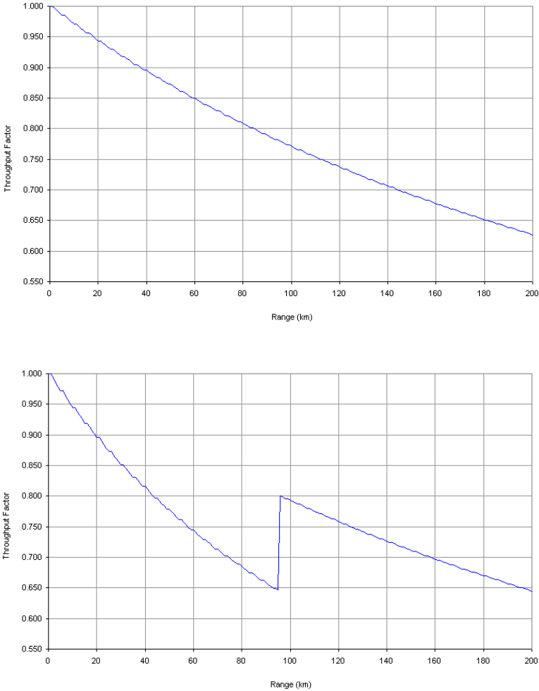
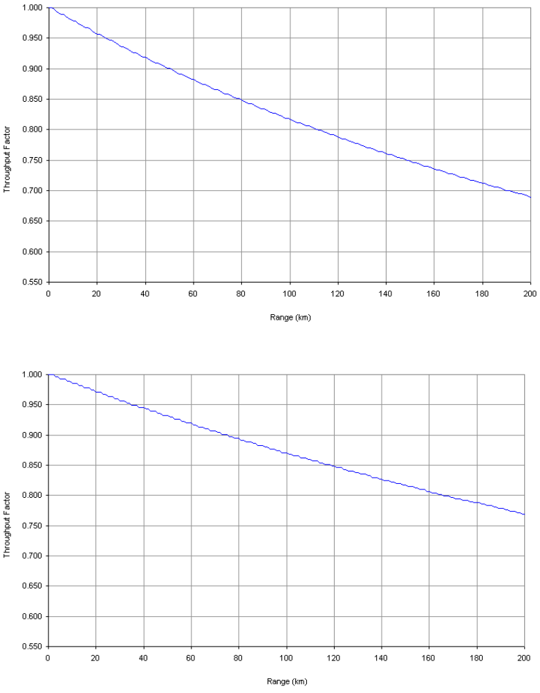
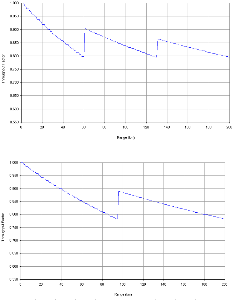
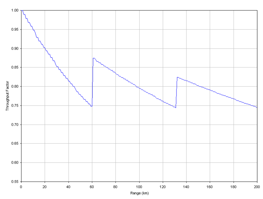
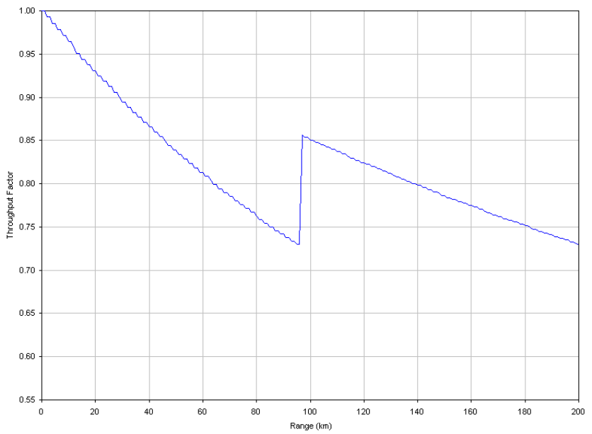
Range adjustment curves
Use these curves to look up the link Range and find the Throughput Factor that must
be applied to adjust the 0 km data throughput rates for the required combination of
Channel Bandwidth, Link Symmetry, Link Optimization, DFS and Link Range (km).
Table 4-67 Range adjustment characteristics
Channel
Band-
width
Link
Sym-
metry
Link
Optimis-
ation
DFS Range
Adjustment
Curve
See Figure
IP A Figure 4-30
1:1
TDM B Figure 4-31
IP C Figure 4-32
2:1
TDM D Figure 4-33
30 MHz
Adaptive IP E Figure 4-34
IP L Figure 4-39
1:1
TDM N Figure 4-40
IP L Figure 4-39
2:1
TDM O Figure 4-41
20 MHz
Adaptive IP C Figure 4-32
IP F Figure 4-35
1:1
TDM G Figure 4-36
None F Figure 4-35
15 MHz
2:1 IP
FCC or
ETSI
C Figure 4-32

Data rate calculations Chapter 4 Reference information
phn-0896_009v003
4-114 UNDER DEVELOPMENT Feb 2010
Channel
Band-
width
Link
Sym-
metry
Link
Optimis-
ation
DFS Range
Adjustment
Curve
See Figure
None H Figure 4-37
TDM
FCC or
ETSI
C Figure 4-32
Adaptive IP A Figure 4-30
IP F Figure 4-35
1:1
TDM K Figure 4-38
IP L Figure 4-39
2:1
TDM L Figure 4-39
10 MHz
Adaptive IP L Figure 4-39
5 MHz 1:1 IP, TDM C Figure 4-32
User Guide: PTP 600 Series Data rate calculations
phn-0896_009v003
Feb 2010 UNDER DEVELOPMENT 4-115
Figure 4-30 PTP 600 range adjustment for data rates, curve A
Figure 4-31 PTP 600 range adjustment for data rates, curve B
Data rate calculations Chapter 4 Reference information
phn-0896_009v003
4-116 UNDER DEVELOPMENT Feb 2010
Figure 4-32 PTP 600 range adjustment for data rates, curve C
Figure 4-33 PTP 600 range adjustment for data rates, curve D
User Guide: PTP 600 Series Data rate calculations
phn-0896_009v003
Feb 2010 UNDER DEVELOPMENT 4-117
Figure 4-34 PTP 600 range adjustment for data rates, curve E
Figure 4-35 PTP 600 range adjustment for data rates, curve F
Data rate calculations Chapter 4 Reference information
phn-0896_009v003
4-118 UNDER DEVELOPMENT Feb 2010
Figure 4-36 PTP 600 range adjustment for data rates, curve G
Figure 4-37 PTP 600 range adjustment for data rates, curve H
User Guide: PTP 600 Series Data rate calculations
phn-0896_009v003
Feb 2010 UNDER DEVELOPMENT 4-119
Figure 4-38 PTP 600 range adjustment for data rates, curve K
Figure 4-39 PTP 600 range adjustment for data rates, curve L
Data rate calculations Chapter 4 Reference information
phn-0896_009v003
4-120 UNDER DEVELOPMENT Feb 2010
Figure 4-40 PTP 600 range adjustment for data rates, curve N
User Guide: PTP 600 Series Data rate calculations
phn-0896_009v003
Feb 2010 UNDER DEVELOPMENT 4-121
Figure 4-41 PTP 600 range adjustment for data rates, curve O
Data rate calculations Chapter 4 Reference information
phn-0896_009v003
4-122 UNDER DEVELOPMENT Feb 2010

Chapter 5
phn-0896_009v003
Feb 2010 UNDER DEVELOPMENT 5-1
Chapter 5 Installation
. . . . . . . . . . . . . . . . . . . . . . . . . . . . . . . . . . . . . . . . . . . . . . . . . . . . . . . . . . . .
.
.
.
.
This chapter provides instructions for installing a PTP 600 link.
CAUTION
Motorola recommends that only qualified personnel undertake the
installation of a PTP 600 Series solution.
Motorola recommends that the practices and procedures detailed in manual
R56 STANDARDS AND GUIDELINES FOR COMMUNICATION SITES
(68P81089E50)
should be applied to all new site build activities. This manual
is provided on the PTP 600 CD-ROM.
The PTP 600 Series installation procedure consists of the following tasks:
• Checking the configuration on page 5-2
• Preparing for site installation on page 5-7
• Cable connection procedures on page 5-8
• Mounting the ODUs on page 5-19
• Installing the UltraSync GPS receiver on page 5-23
• Installing the GPS receiver for PTP-SYNC on page 5-28
• Installing PTP-SYNC on page 5-36
• Connecting the ODU, PIDU and LPUs on page 5-43
• Installing E1 and T1 on page 5-50
• Establishing a radio link on page 5-59
If a connectorized PTP 600 variant is to be installed, see Chapter 8 Connectorized PTP
600 series.
Legal disclaimer
IN NO EVENT SHALL MOTOROLA, INC. BE LIABLE FOR ANY INJURY TO ANY
PERSONS OR ANY DAMAGE CAUSED DURING THE INSTALLATION OF THE
MOTOROLA PTP 600 SERIES PRODUCT.

Checking the configuration Chapter 5 Installation
phn-0896_009v003
5-2 UNDER DEVELOPMENT Feb 2010
Checking the configuration
This section describes how to configure the management PC, power up the unit,
connect it to the PC and check the factory configuration. Motorola recommends that
these tasks should be performed before site installation.
IP addresses of the Master and Slave units
The PTP 600 is supplied as a pair of matched units, a Master and a Slave. The usual
default IP addresses are:
• Master: 169.254.1.2
• Slave: 169.254.1.1
However, some units may have been configured with different IP addresses:
• Master: 10.10.10.11
• Slave: 10.10.10.10
Configuring the IP interface on the PC
Before powering up the unit, set up the IP configuration of the management PC.
If the default IP addresses of the Master and Slave units are 169.254.1.2 and
169.254.1.1, then set up the IP configuration of the PC as follows:
• Enter an IP address of 169.254.1.n, where n is any value between 3 and 254. Do
not use 169.254.1.1 or 169.254.1.2.
• Enter a subnet mask of 255.255.0.0.
If the default IP addresses of the Master and Slave units are 10.10.10.11 and
10.10.10.10, then set up the IP configuration of the PC as follows:
• Enter an IP address of 10.10.10.n, where n is between 2 and 254. Do not use
10.10.10.10 or 10.10.10.11.
• Enter a subnet mask of 255.255.0.0.
User Guide: PTP 600 Series Checking the configuration
phn-0896_009v003
Feb 2010 UNDER DEVELOPMENT 5-3
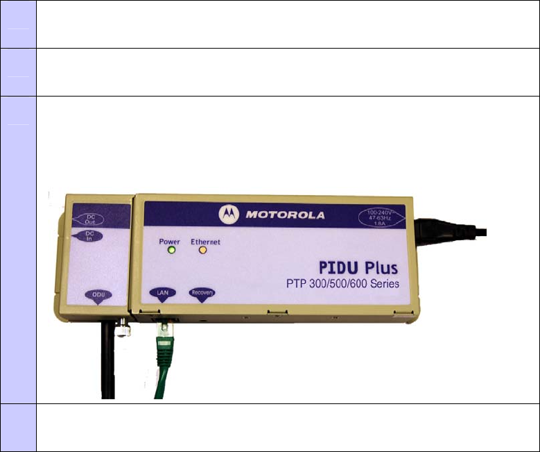
Powering up and connecting the PIDU Plus
When the management PC has been configured with the correct IP address and subnet
mask, the PIDU can be powered up and connected to the management PC. To power
up the PIDU and connect it to the PC, proceed as follows:
Procedure 5-1 Power up and connect the PIDU Plus
1 Apply mains or battery power to the PIDU Plus. The green Power LED
should illuminate continuously.
2 After 45 seconds, the orange Ethernet LED should be observed starting
with 10 slow flashes.
3 Connect the CAT5e cable from the LAN port of the PIDU Plus to the
management PC (either via the network or directly using a standard CAT5
patch cable). The Ethernet LED should blink randomly as traffic passes
through.
4 If the Power and Ethernet LEDs do not illuminate correctly, refer to Test
link end hardware on page 7-2.

Checking the configuration Chapter 5 Installation
phn-0896_009v003
5-4 UNDER DEVELOPMENT Feb 2010
Opening the web interface
When the unit has been powered up and connected to the management PC, the web
interface can be opened. To open the PTP 600 web interface on the management PC,
proceed as follows:
Procedure 5-2 Open the web interface
1 Start the web browser.
2 Type the IP address of the unit into the address frame, for example:
169.254.1.2.
3 Press ENTER. The login page (Figure 6-7) is displayed.
4 Leave the Password blank and select Login. The web interface menu
(Figure 6-1) and System Summary page (Figure 6-2) are displayed.
Checking LAN configuration
The unit must be configured to be compatible with the network. It is particularly
important to avoid IP address conflicts. To check the LAN configuration, proceed as
follows:
Procedure 5-3 Check LAN configuration
1 Design the desired configuration of the network to be installed, noting the
required IP Address, Subnet Mask and Gateway IP Address of the Master
and Slave units.
2 Select LAN Configuration from the menu. The LAN Configuration page
(Figure 6-20) is displayed.
3 Compare the required IP Address, Subnet Mask and Gateway IP Address to
current settings.
4 If the current settings are different, update them as described in
Configuring the IP and Ethernet interfaces on page 6-42.

User Guide: PTP 600 Series Checking the configuration
phn-0896_009v003
Feb 2010 UNDER DEVELOPMENT 5-5
Checking software version
The software version installed on the unit may not be the latest one available from
Motorola. To check and update the software version, proceed as follows:
Procedure 5-4 Check software configuration
1 Select Status from the menu. The System Status page (Figure 6-4) is
displayed.
2 Check that the Software Version attribute in the System Status page is the
same as the latest PTP 600 software version in
http://www.motorola.com/ptp/support.
3 If it is not the latest, upgrade it as described in Upgrading PTP 600
software on page 6-84.
Checking region code
The unit is supplied with two alternative license keys, one of which is factory
configured. To check that the configured license key is for the required Region Code,
proceed as follows:
Procedure 5-5 Check region code
1 Select Status from the menu. The System Status page (Figure 6-4) is
displayed.
2 Check that the required Region Code attribute is in the System Status page.
3 If it is not, replace the license key of the unit with the supplied alternative
license key, as described in Entering a license key on page 6-80.

Checking the configuration Chapter 5 Installation
phn-0896_009v003
5-6 UNDER DEVELOPMENT Feb 2010
Checking wireless configuration
To check that the factory wireless configuration meets network requirements, proceed
as follows:
Procedure 5-6 Check wireless configuration
1 Select Installation from the menu. The Current Installation Summary
page(Figure 6-27)is displayed.
2 Confirm that the Target MAC Address, Master Slave Mode, Tx Max Power,
Link Symmetry and Target Range attributes meet network requirements.
3 If they do not, update them as described in Installation pages on page 6-
51.

User Guide: PTP 600 Series Preparing for site installation
phn-0896_009v003
Feb 2010 UNDER DEVELOPMENT 5-7
Preparing for site installation
Checks
Before proceeding with the installation, perform the following checks:
• Plan the link, as described in Chapter 2 Planning considerations.
• Check the configuration of the Master and Slave units, as described in Checking
the configuration on page 5-2.
• Check the contents of all packages against the parts lists shown in the packing
list.
• Ensure that qualified installers are available to undertake the work.
• Ensure that the correct safety precautions are observed.
Tools required
The following specific tools are required to install a PTP 600 Series, in addition to
general tools:
• 13mm wrench and 22 mm wrench for use with the glands
• RJ45 crimp tool (it must be the correct tool for the type of RJ45 being used)
• Personal Computer (PC) with 10, 100 or 1000 BaseT Ethernet
• Either Internet Explorer version 6 or higher, or FireFox 2.0 or higher are
recommended.
• Ethernet patch cables
• Motorola PTP LINKPlanner report for this link

Cable connection procedures Chapter 5 Installation
phn-0896_009v003
5-8 UNDER DEVELOPMENT Feb 2010
Cable connection procedures
This section describes three procedures that may be performed repeatedly in the
course of site installation:
• Preparing the supported Superior Essex cable.
• Installing a cable grounding kit.
• Installing a lightning protection unit (LPU)
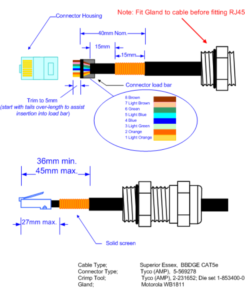
Preparing the supported Superior Essex cable
The maximum cable length between the ODU and the user’s network equipment is
100m (330 ft). Cable lengths up to 300m (984 ft) can be used where the PIDU Plus to
ODU cable is supplying power only, that is, when using the PTP 600 Series optical
interface.
For details of recommended cables and connectors, refer to Cables and connectors on
page 1-15.
WARNING
The copper screen of the supported Superior Essex cable is very
sharp and may cause personal injury. When preparing the Superior
Essex cable, take the following safety precautions:
o ALWAYS wear cut resistant gloves (check the label to ensure they are cut
resistant).
o ALWAYS wear protective eyewear.
o ALWAYS use a rotary blade tool to strip the cable (DO NOT use a bladed
knife). To use the rotary blade tool, fit it around the outer cable sheaf and
rotate the cutter around the cable once or twice. The stripped outer
section can then be removed.
Cable connection procedures Chapter 5 Installation
phn-0896_009v003
5-10 UNDER DEVELOPMENT Feb 2010
CAUTION
Check that the crimp tool matches the RJ45 connector being used, otherwise
the cable or connector may be damaged.
NOTE
The cable inner sheaf must be located correctly under the connector housing
tang. If this is not done correctly, there is no strain relief on the cable
terminations.
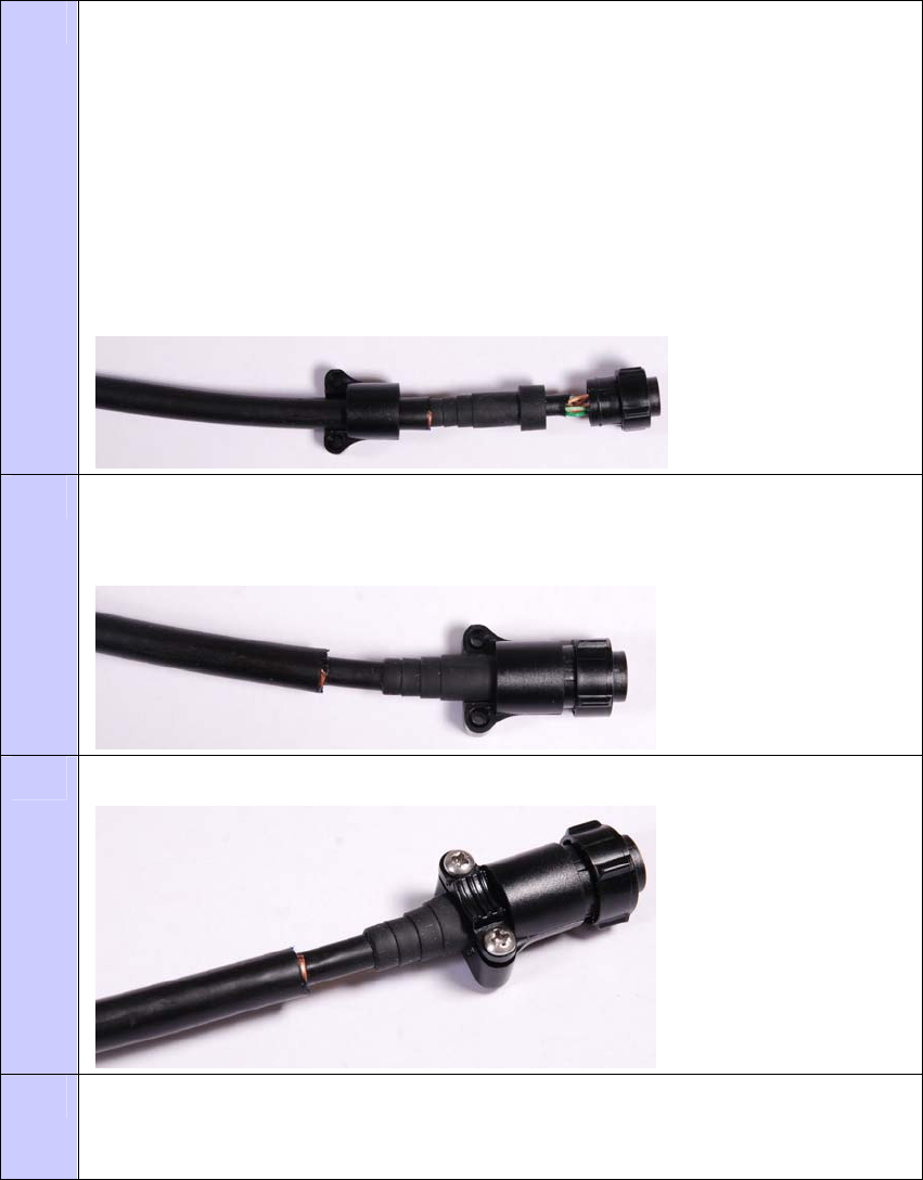
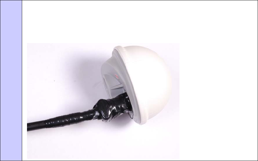
Both ends of the ODU cable are terminated in the same way. The above procedure
should be repeated for the PIDU Plus end of the cable when the cable routing process
is complete. This assumes that the installation uses PTP LPUs. If not, then the PIDU
Plus end of the cable does not require a Gland, but just the RJ45.
NOTE
The PIDU Plus end of the cable does not employ a cable gland.
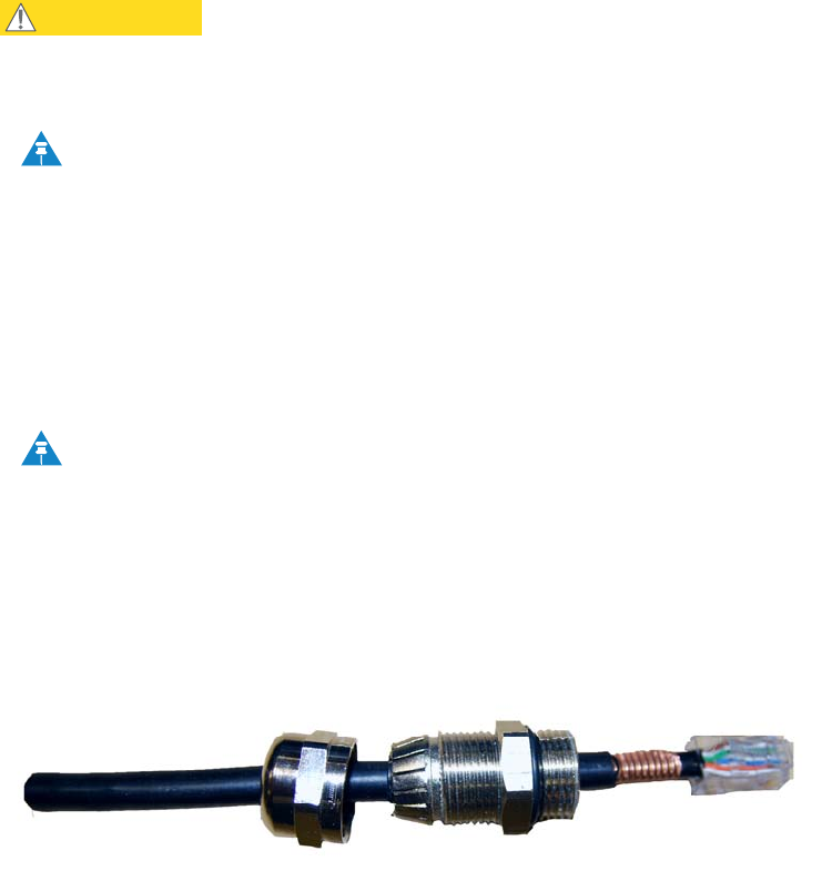
Figure 5-2 shows a completed ODU to PIDU Plus cable.
Figure 5-2 Completed ODU connector
User Guide: PTP 600 Series Cable connection procedures
phn-0896_009v003
Feb 2010 UNDER DEVELOPMENT 5-11
Grounding the drop cable to a metal tower or mast
For installations where the ODU or GPS receiver (if installed) are fitted to a metal
tower or mast, the screen of the supported Superior Essex cable must be ground
bonded to the tower or mast.
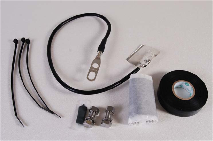
The cable grounding kit for 1/4” and 3/8” cable (Figure 5-3) contains the following
components:
• 1 x grounding cable with grounding 2 hole lug fitted (M10)
• 1 x self Amalgamating tape
• 1 x PVC tape
• 3 x tie wraps
• 2 x bolt, washer and nut
Figure 5-3 Cable grounding kit for 1/4” and 3/8” cable
Cable connection procedures Chapter 5 Installation
phn-0896_009v003
5-12 UNDER DEVELOPMENT Feb 2010
To ground the supported Superior Essex cable to a metal tower or mast, proceed as
follows:
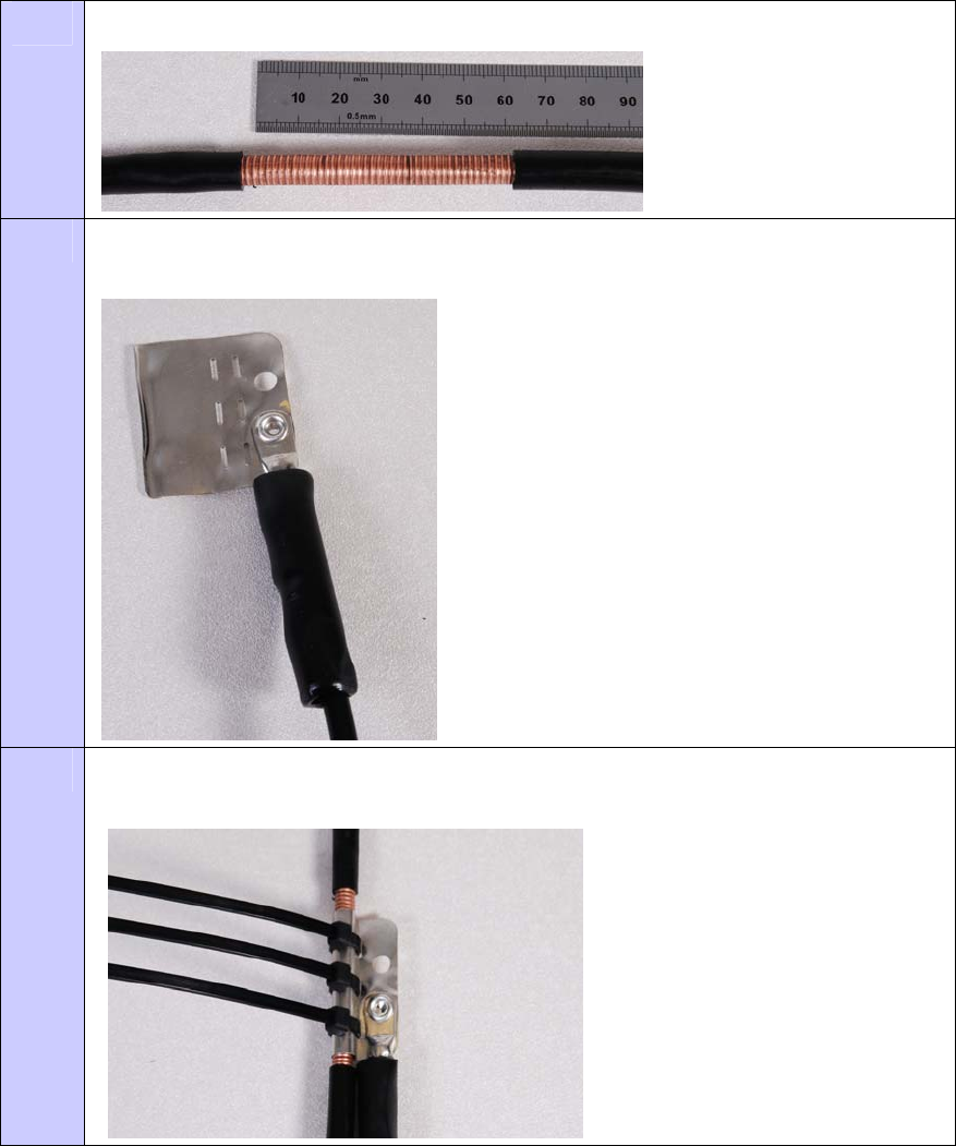
Procedure 5-7 Ground the drop cable
1 Remove 60mm (2.5inches) of the drop cable outer jacket.
2 Cut 38mm (1.5 inches) of rubber tape (self amalgamating) and fit to the ground
cable lug. Wrap the tape completely around the lug and cable.
3 Fold the ground wire strap around the drop cable screen. Fit cable ties and tighten
with pliers.
User Guide: PTP 600 Series Cable connection procedures
phn-0896_009v003
Feb 2010 UNDER DEVELOPMENT 5-13
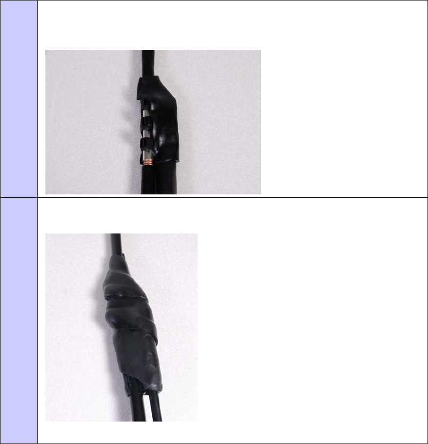
4 Cut the surplus from the cable ties. Cut a 38mm (1.5 inches) section of self-
amalgamating tape and fit to the ground cable lug. Wrap the self-amalgamating
tape completely around the lug and cable.
5 Use the remainder of the self-amalgamating tape to wrap the complete assembly.
Press the tape edges together so that there are no gaps.
Cable connection procedures Chapter 5 Installation
phn-0896_009v003
5-14 UNDER DEVELOPMENT Feb 2010
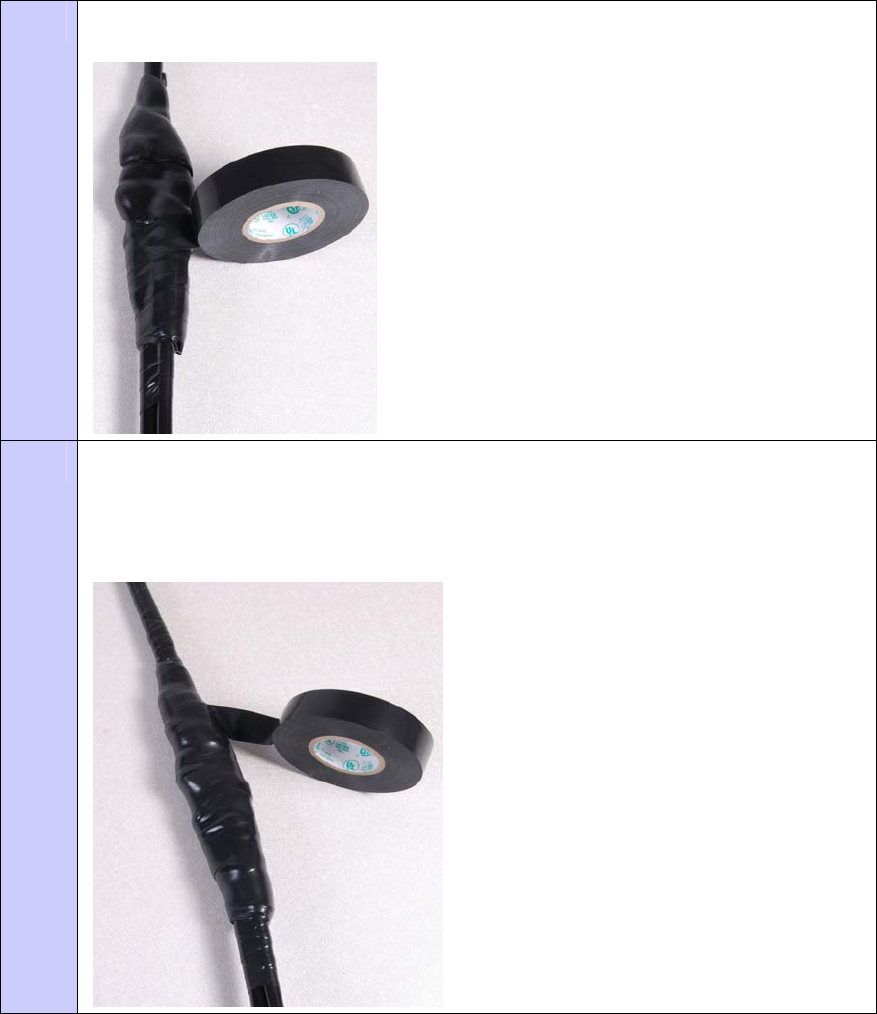
6 Wrap a layer of PVC tape, starting from 25mm (1 inch) above the outer jacket and
finishing 25mm (1 inch) below the self-amalgating tape, over lapping at half width.
7 Repeat with a further four layers of PVC tape.
Start the second layer 25mm (1 inch) above the first layer tape, start the third layer
below the finish of the second layer. Continue until five layers have been applied,
always over lapping at half width.
User Guide: PTP 600 Series Cable connection procedures
phn-0896_009v003
Feb 2010 UNDER DEVELOPMENT 5-15
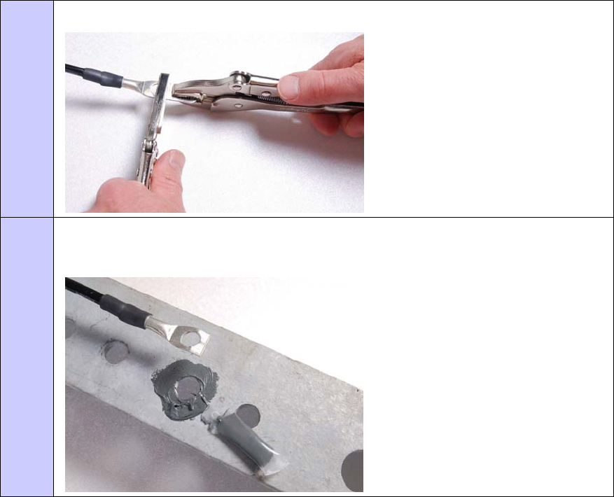
8 If a single hole tag is required at the mast end, modify the two hole tag as shown.
9 Apply the anti-oxidant compound liberally applied between the two metals.
If paint is present, remove it to provide a good electrical contact.
Cable connection procedures Chapter 5 Installation
phn-0896_009v003
5-16 UNDER DEVELOPMENT Feb 2010
Connecting the drop cable to an ODU or LPU
NOTE
This procedure contains illustrations of an ODU, but it applies in principle to
both the ODU and the LPU.
To connect the supported Superior Essex cable with a gland to a unit (LPU or ODU),
proceed as follows:
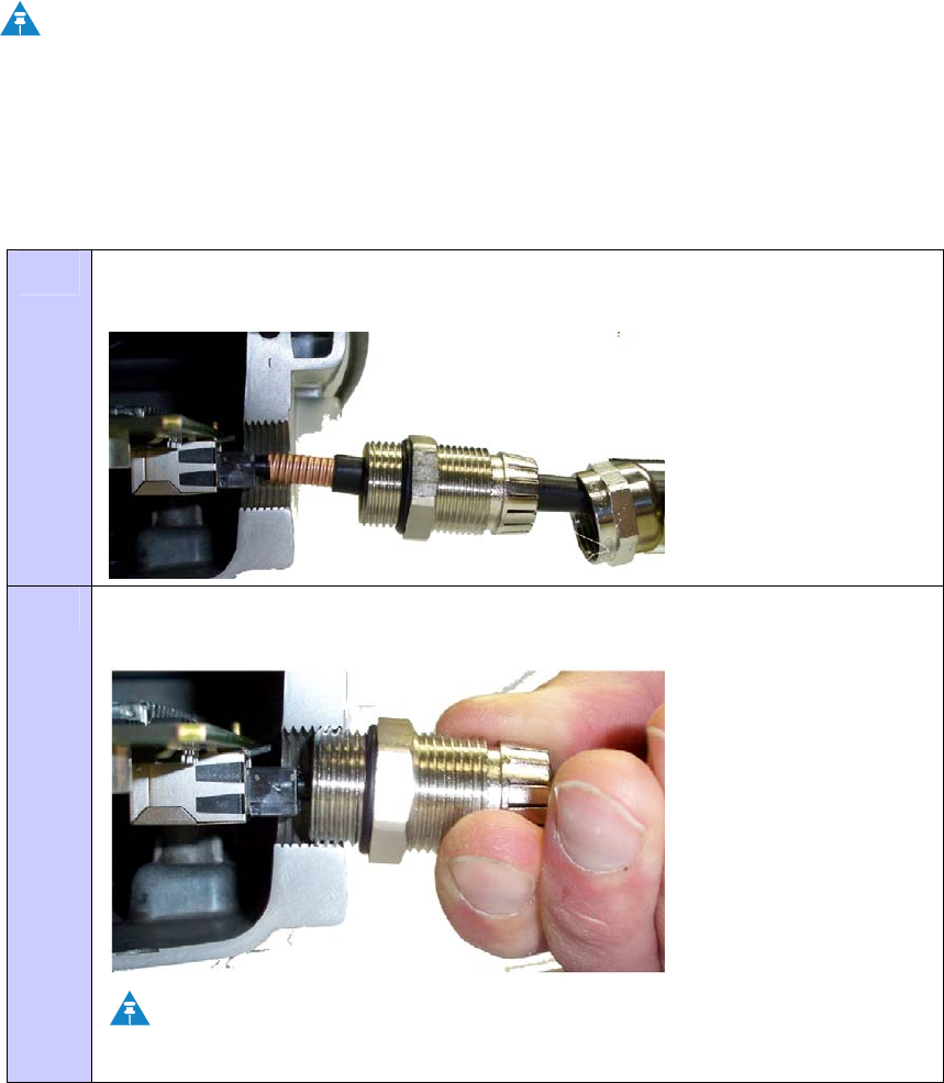
Procedure 5-8 Connect the drop cable with a gland to a unit (LPU or ODU)
1 Insert the RJ45 plug into the socket in the unit, making sure that the locking tab
snaps home.
2 Support the drop cable and gently hand screw the gland body into the unit until
the O ring seal is flush to the unit body.
NOTE
Do not fit the back shell prior to securing the gland body.
User Guide: PTP 600 Series Cable connection procedures
phn-0896_009v003
Feb 2010 UNDER DEVELOPMENT 5-17
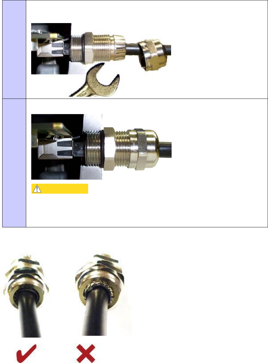
3 Once the gland is fully hand screwed into the unit, tighten it with a spanner to
torque 10 Nm (7.37 ftlbs).
4 When the gland body has been fitted, tighten the gland back shell.
CAUTION
Do not over-tighten the gland back shell, as the internal seal and structure
may be damaged. Figure 5-4 shows correctly tightened and over-tightened
gland back shells.
Figure 5-4 Correct and incorrect tightening of cable gland back shell
Cable connection procedures Chapter 5 Installation
phn-0896_009v003
5-18 UNDER DEVELOPMENT Feb 2010
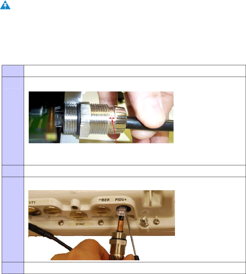
Disconnecting the drop cable from an ODU or LPU
NOTE
This procedure contains illustrations of an ODU, but it applies in principle to
both the ODU and the LPU.
To disconnect the supported Superior Essex cable with a gland from a unit (LPU or
ODU), proceed as follows:
Procedure 5-9 Disconnect the drop cable with a gland from a unit (LPU or ODU)
1 Remove the gland back shell.
2 Wiggle the drop cable to release the tension of the gland body.
When the tension in the glad body is released, a gap opens at the point shown in
red in the above photograph.
3 Unscrew the gland body.
4 Use a small screwdriver to depress the RJ45 locking cap
5 Unplug the RJ45.
User Guide: PTP 600 Series Mounting the ODUs
phn-0896_009v003
Feb 2010 UNDER DEVELOPMENT 5-19
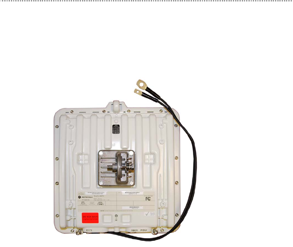
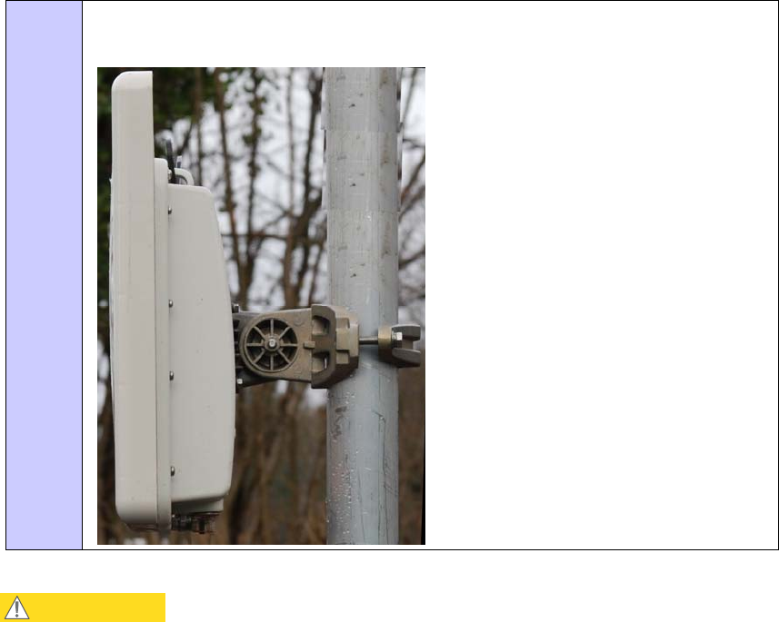
Mounting the ODUs
Mounting bracket
The ODU is pre-fitted with a mounting bracket (designed to ease installation) and with
earth bonding leads (Figure 5-5).
Figure 5-5 ODU with mounting bracket and earth bonding leads
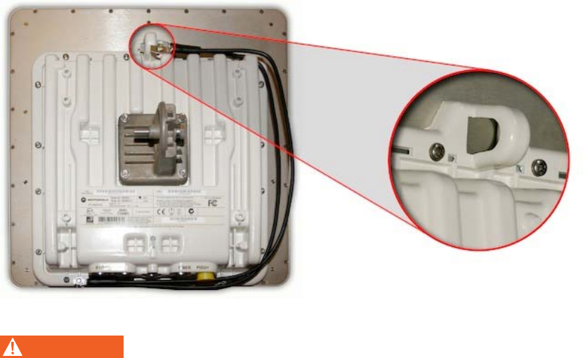
Hoist and safety loop
Use the integral safety loop (Figure 5-6) for hoisting the ODU up a mast, tower or
building. When the ODU is in position, use the safety loop as a fixing point to secure a
permanent lanyard from the mast, tower or building to the ODU, as a precaution
against mounting failure.
Mounting the ODUs Chapter 5 Installation
phn-0896_009v003
5-20 UNDER DEVELOPMENT Feb 2010
Figure 5-6 Integral safety loop
WARNING
Observe the following safety precautions before hoisting the ODU:
o The safety lanyard must not exceed 1m (approx 3 ft) in length. The
lanyard must be made from a material that does not degrade in an outdoor
environment.
o The safety lanyard must be fixed to a separate fixing point that is not part
of the direct mounting system for the ODU.
o If the safety loop or its fixing is damaged in any way or has been exposed
to a shock loading due to a fall, replace it with a new one before
undertaking any further operations.
User Guide: PTP 600 Series Mounting the ODUs
phn-0896_009v003
Feb 2010 UNDER DEVELOPMENT 5-21
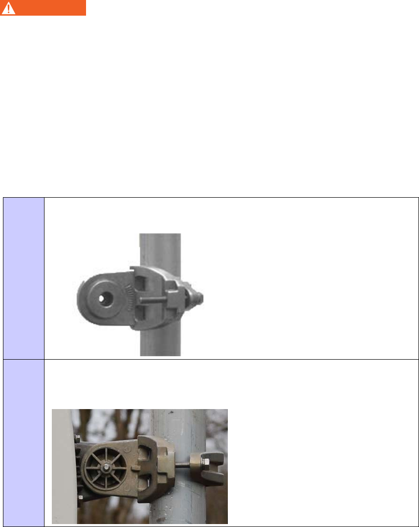
ODU mounting procedure
WARNING
To prevent failure of the assembly, observe the following precautions
when mounting the ODU:
o Do not remove the pre-fitted mounting bracket from the ODU.
o Do not mount the ODU on poles with diameter less than 50mm (2”) or
greater than 75mm (3”). The ODU mounting bracket is designed to work
only with poles with diameter in the 50 mm (2”) to 75 mm (3”) range.
o Do not over-tighten the bolts.
The ODU must be mounted using the following steps, ensuring that the cable entry is
at the bottom:
Procedure 5-10 Mounting the ODU
1 Attach the bracket strap to the pole using M8 x 70 mm bolts, M8 flat washers
and M8 coil washers. Tighten to ensure the assembly grips but can be adjusted.
2 Offer the ODU (with pre-fitted mounting bracket) to the bracket strap and affix
using the captive M8 bolt. Tighten to ensure the assembly grips, but can be
adjusted on the pole.
Mounting the ODUs Chapter 5 Installation
phn-0896_009v003
5-22 UNDER DEVELOPMENT Feb 2010
3 Adjust the elevation and azimuth of the unit before tightening to the required
torque settings of 14 Nm (11 lb ft) for both bolts.
CAUTION
Attach the free end of one earth bonding lead (large tag M10) to the tower
metal work. On no account must this be attached to the mounting bracket
bolts.
The enclosure and mounting brackets of the PTP 600 Series product range are capable
of withstanding wind speeds up to 151mph (242kph). The installer should ensure that
the structure the bridge is fixed to is also capable of withstanding the prevalent wind
speeds and loads.

User Guide: PTP 600 Series Installing the UltraSync GPS receiver
phn-0896_009v003
Feb 2010 UNDER DEVELOPMENT 5-23
Installing the UltraSync GPS receiver
Recommended kit
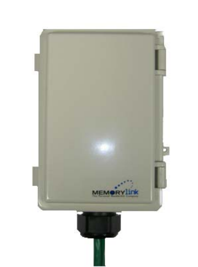
The UltraSync installation kit includes the following:
• GPS synchronization unit from MemoryLink (see Figure 5-7), with three attached
terminated Ethernet and sync cables and cable glands (2) which connect directly
to a PTP 600 Series ODU.
• Mounting bracket and mounting bracket bolts
• Outdoor rated UV resistant cable tie
• UltraSync user manual.
In addition to the hardware mentioned above, Motorola recommends the installation of
appropriate lightning protection with PTP LPUs, as described in Lightning protection
and E1/T1 on page 5-57.
NOTE
Refer to the UltraSync user manual for details on the lengths of cables used
to connect the UltraSync to the ODU and PTP LPU.
Installing the UltraSync GPS receiver Chapter 5 Installation
phn-0896_009v003
5-24 UNDER DEVELOPMENT Feb 2010
Figure 5-7 UltraSync unit
User Guide: PTP 600 Series Installing the UltraSync GPS receiver
phn-0896_009v003
Feb 2010 UNDER DEVELOPMENT 5-25
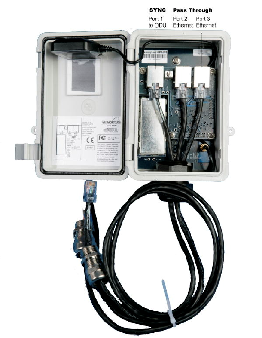
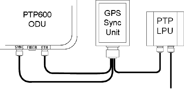
UltraSync unit connections
Figure 5-8 shows the inside of the UltraSync unit and Figure 5-9 is a diagram that
shows how to connect the UltraSync unit to the ODU and the LPU.
Figure 5-8 UltraSync unit connections
User Guide: PTP 600 Series Installing the UltraSync GPS receiver
phn-0896_009v003
Feb 2010 UNDER DEVELOPMENT 5-27
Figure 5-10 UltraSync unit complete installation

Installing the GPS receiver for PTP-SYNC Chapter 5 Installation
phn-0896_009v003
5-28 UNDER DEVELOPMENT Feb 2010
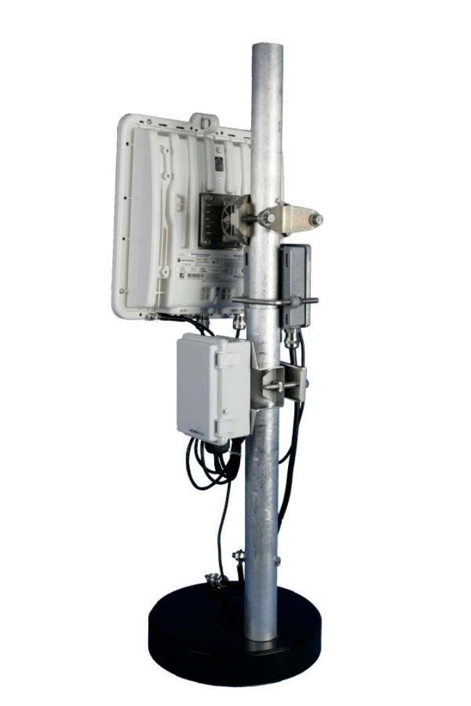
Installing the GPS receiver for PTP-SYNC
If the chosen TDD synchronization method requires a GPS timing reference source
(see TDD synchronization configuration options on page 2-12), then a GPS receiver
must be installed. Motorola recommends that the Trimble GPS receiver should be
used. This section describes the installation procedure for the Trimble GPS receiver.
CAUTION
Prior to power-up of equipment, ensure that all cables are connected to the
correct interfaces of the PTP-SYNC unit and the GPS receiver module.
Failure to do so may result in damage to the equipment.
Recommended kit
Trimble GPS receiver
One Trimble GPS receiver is required.
Cables and connectors
The drop cable connecting the GPS receiver to the LPU must be of the supported
Superior Essex cable type. The drop cable must have a Trimble 12-pin connector at the
GPS end, and an RJ45 connector and gland at the LPU end. For more information,
refer to Outdoor connections on page 1-15.
LPU
One LPU kit (Figure 2-10) is required.

User Guide: PTP 600 Series Installing the GPS receiver for PTP-SYNC
phn-0896_009v003
Feb 2010 UNDER DEVELOPMENT 5-29
Cable grounding kit
If the GPS receiver is mounted on a metal tower or mast, one or more cable grounding
kits (Figure 5-3) are required to ground bond the drop cable at the correct grounding
points (Figure 2-21).
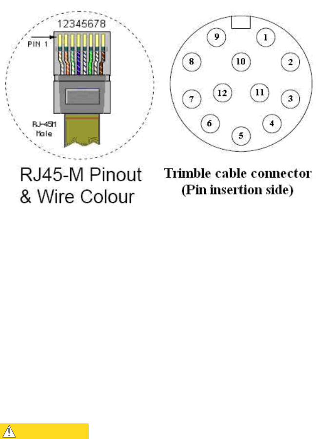
Trimble GPS connector pin definition
Table 5-1 shows how the Trimble connector pins (at the GPS end of the drop cable)
map to the RJ45 connector pins (at the LPU end). Figure 5-11 shows the positions of
the pins in each type of connector.
Table 5-1 Trimble connector to RJ45 pin mappings
RJ45 wire colour Trimble
12-pin conn
Function
Conventional
Superior Essex
PTP-SYNC (J10)
RJ45 pin
1 DC Pwr (12V) Orange/White Light Orange 1
2 RxB- Brown Brown 8
3 RxB+ Brown/White Light Brown 7
4 TxB- Blue Blue 4
5 TxB+ Blue/White Light Blue 5
6 RxA- N.C N.C ---
7 RxA+ N.C N.C ---
8 TxA- N.C N.C ---
9 DC Ground Orange Orange 2
10 TxA+ N.C N.C ---
11 Tx1PPS+ Green/White Light Green 3
12 Tx1PPS- Green Green 6
Installing the GPS receiver for PTP-SYNC Chapter 5 Installation
phn-0896_009v003
5-30 UNDER DEVELOPMENT Feb 2010
Figure 5-11 RJ45 and Trimble connector pins
Mounting the GPS receiver
Mount the GPS receiver (following manufacturer’s instructions) upon either an
external wall or a metal tower or mast. Motorola recommends that the receiver is wall
mounted. For more information on these options, refer to Protection of the GPS
receiver for PTP-SYNC on page 2-36.
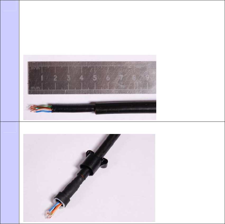
Connecting the GPS receiver to the drop cable
The drop cable must be connected the GPS receiver using the Trimble connector
provided.
CAUTION
The supported Superior Essex cable has solid copper conductors. There is a
limited number of times each conductor can be bent before it fatigues and
fails.
To fit the Trimble 12-pin connector to the drop cable, proceed as follows:
User Guide: PTP 600 Series Installing the GPS receiver for PTP-SYNC
phn-0896_009v003
Feb 2010 UNDER DEVELOPMENT 5-31
Procedure 5-11 Connect drop cable to Trimble GPS receiver
1 Prepare the drop cable end as follows:
Bare back the cable outer and copper screen to 50mm.
Bare back the cable inner to 17mm.
Un-twist the cable pairs.
Strip the individual conductors to 5mm.
2 Fit the adaptor outer, associated boot, and boot insert.
Installing the GPS receiver for PTP-SYNC Chapter 5 Installation
phn-0896_009v003
5-32 UNDER DEVELOPMENT Feb 2010
3 Connect the socket contacts using either of the following techniques:
Crimp
Crimp the socket contacts onto each of the conductors using the correct crimp
tool and positioner, setting the wire size selector to ‘3’ for 24AWG wire.
Solder
When soldering the socket contacts onto each of the conductors, ensure that
there is no solder or flux residue on the outside of the contact. Care should also
be taken that the individual conductor insulation does not peel back with the
soldering heat, allowing possible shorts when assembled into the connector shell.
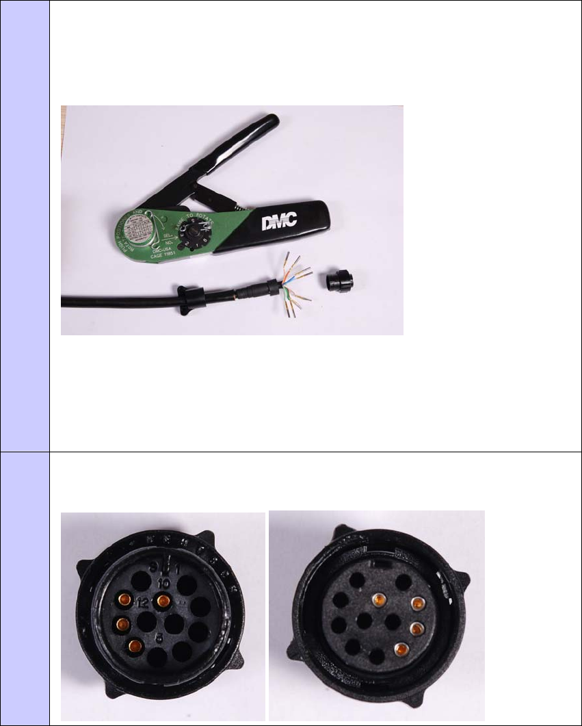
4 Fit four contacts into the unused locations, to provide strength and sealing.
Pin insert side: Connector mating side:
User Guide: PTP 600 Series Installing the GPS receiver for PTP-SYNC
phn-0896_009v003
Feb 2010 UNDER DEVELOPMENT 5-33
5 Insert the eight contacts into the connector body in accordance with Table 5-1.
It is easiest to insert the pins from the inside out, in the order 12, 11, 9, 5, 4, 3, 2,
1. Push the contacts in so that the shoulder on the contact fits into the hole in the
connector shell. When all contacts have been fitted, pushed them in further to
engage with the locking mechanism in the connector shell. This can be done by
applying pressure to the contact with a small diameter stiff object, such as
tweezers.
If a contact is pushed in to the point where the locking mechanism engages
before all of the contacts have been inserted it will limit the amount of room
available to fit the remaining contacts, requiring harder bends to be applied.
6 Fit the adaptor to the connector shell. The plastic ring fits inside the rubber boot
and ensures a tight fit when the adaptor body is clipped onto the connector shell.
Be aware that the adaptor body is a hard push fit onto the connector shell.
7 Fit the strain relief clip.
8 Connect the adapter to the GPS, then wrap a layer of self-amalgamating tape,
starting 25mm below the bared back outer of the cable and finishing at the GPS
housing.
Installing the GPS receiver for PTP-SYNC Chapter 5 Installation
phn-0896_009v003
5-34 UNDER DEVELOPMENT Feb 2010
9 Wrap a layer of PVC tape, starting just below the start of the self-amalgamating
tape and finishing at the GPS housing, overlapping at half width.
Repeat with a further four layers of PVC tape alternating the start and finish
ends.

User Guide: PTP 600 Series Installing the GPS receiver for PTP-SYNC
phn-0896_009v003
Feb 2010 UNDER DEVELOPMENT 5-35
Grounding the GPS receiver drop cable
Wall installation
For installations where the GPS receiver module is fitted to an external wall, it is not
necessary to ground bond the GPS cable.
Metal tower or mast installation
For installations where the GPS receiver module is fitted to a metal tower or mast, the
screen of the GPS cable MUST be ground bonded to the metal tower or mast.
To identify the required grounding points, refer to Mounting the GPS receiver module
on a metal tower or mast on page 2-37.
To ground the cable, follow the procedure described in Grounding the drop cable to a
metal tower or mast on page 5-11.
Mounting the LPU and connecting the GPS receiver
To mount the LPU and connect it to the drop cable from the GPS receiver, proceed as
follows:
Procedure 5-12 Mount LPU and connect to GPS receiver
1 Check the contents of the LPU box (Figure 2-10).
2 Mount the LPU (following manufacturer’s instructions) at the point where the
drop cable from the GPS receiver enters the building (Figure 2-20 or Figure
2-21). Mount the LPU vertically with cable glands facing downwards.
3 Prepare the LPU end of the GPS receiver drop cable as described in Preparing
the supported Superior Essex cable on page 5-8.
4 Connect the cable gland of the GPS receiver drop cable to the LPU as described
in Connecting the drop cable to an ODU or LPU on page 5-16.
5 Make an unscreened CAT5e cable to connect the LPU to the ‘GPS/SYNC IN’
interface of the PTP-SYNC unit.
Installing PTP-SYNC Chapter 5 Installation
phn-0896_009v003
5-36 UNDER DEVELOPMENT Feb 2010
Installing PTP-SYNC
Recommended kit
PTP-SYNC kit
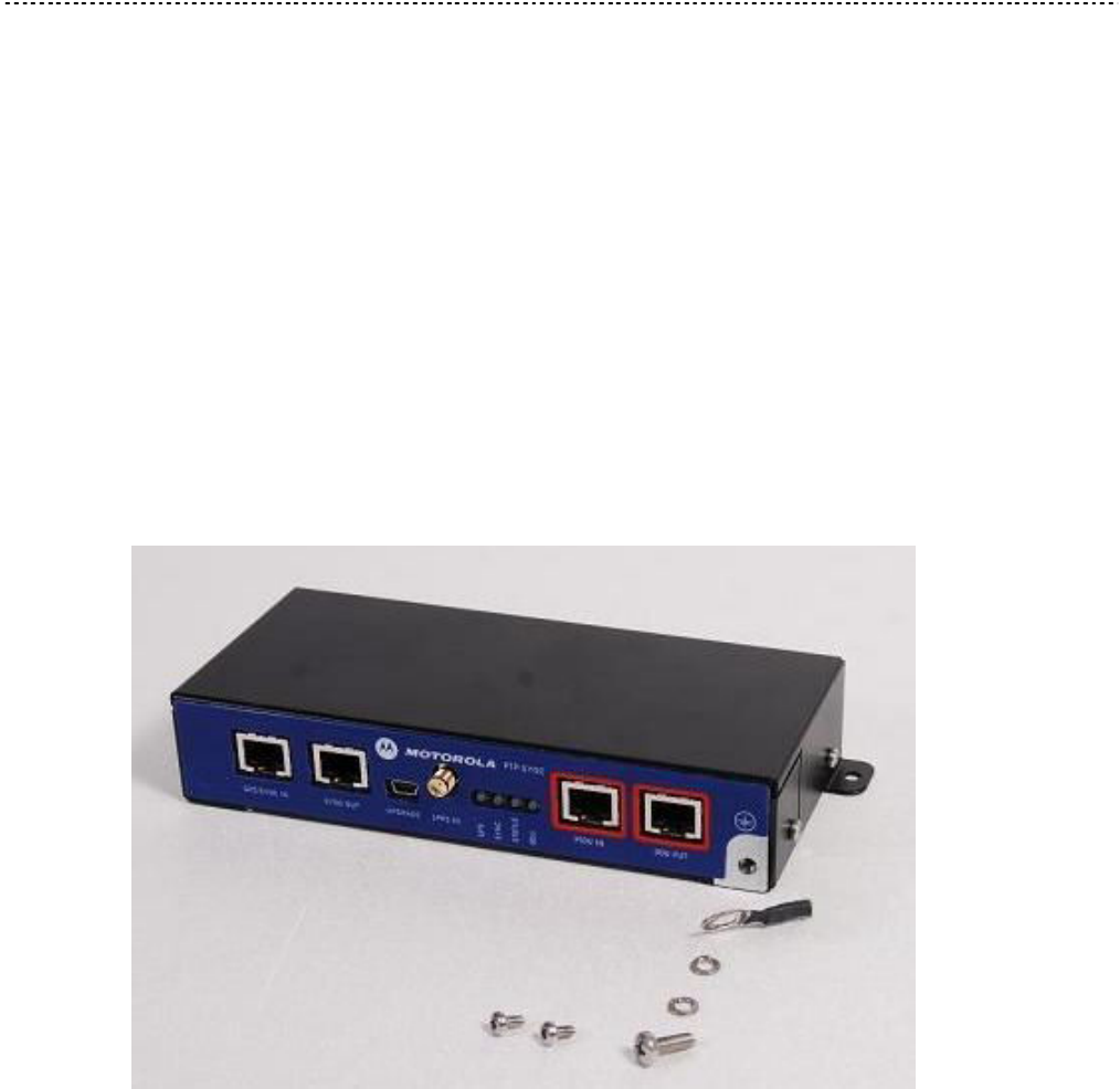
The PTP-SYNC kit (Figure 5-12) contains the following components:
• 1 x PTP-SYNC unit
• 1 x M4 pan screw
• 2 x M4 washers
• 2 x M3 (6mm) torx drive screws
• 1 x lug for unit earth (cable not supplied)
Figure 5-12 PTP-SYNC kit
GPS timing kit
The GPS receiver module is an optional item that must be purchased separately, if the
chosen PTP-SYNC system configuration includes GPS.
User Guide: PTP 600 Series Installing PTP-SYNC
phn-0896_009v003
Feb 2010 UNDER DEVELOPMENT 5-37
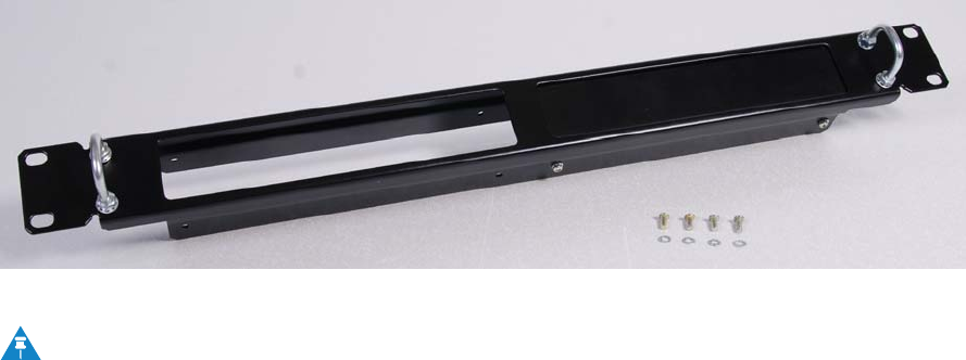
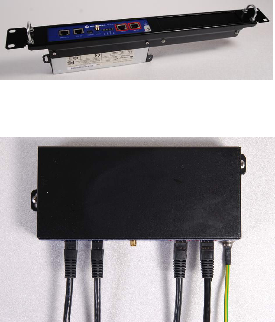
Rack mount installation kit
The PTP800 CMU / PTP-SYNC 19” rack mount installation kit (Figure 5-13) is an
optional item that must be purchased separately, if required. This kit contains the
following components:
• 1 x rack bracket
• 8 x M3 washers
• 8 x M3 screws
• 1 x rack mount blank plate
• 8 x M5 nuts
• 8 x M5 washers
• 2 x rack handles
Figure 5-13 PTP800 CMU / PTP-SYNC 19” rack mount installation kit
NOTE
Ethernet cables are not provided as part of the PTP-SYNC product or as part
of the GPS Module Kit.
PTP-SYNC unit rack or wall mounting
The PTP-SYNC unit can either be rack mounted indoors or wall mounted indoors.
Rack mounted
Securing screws for PTP-SYNC within the rack mount are fitted to the underside
(Figure 5-14).
Installing PTP-SYNC Chapter 5 Installation
phn-0896_009v003
5-38 UNDER DEVELOPMENT Feb 2010
Figure 5-14 Rack mount securing screws for PTP-SYNC
Wall mounted
If the PTP-SYNC is to be wall-mounted, the unit must be fitted vertically with unit
interfaces and cabling facing downwards (Figure 5-15).
Figure 5-15 PTP-SYNC mounted on wall
User Guide: PTP 600 Series Installing PTP-SYNC
phn-0896_009v003
Feb 2010 UNDER DEVELOPMENT 5-39
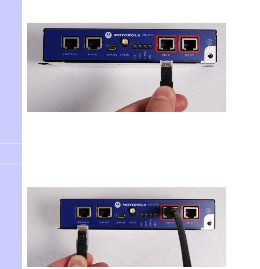
Connecting up PTP-SYNC
To connect the PTP-SYNC to the PIDU, ODU, GPS receiver (if fitted), and LPU (if
fitted), proceed as follows:
Procedure 5-13 Weather-proof the GPS receiver module cable
1 Use a one meter un-screened CAT5e Ethernet cable (refer to Cables and
connectors on page 1-15) and connect the PIDU to the PTP-SYNC.
2 If using a GPS timing reference, install the GPS unit as described in Installing
the GPS receiver for PTP-SYNC on page 5-28) The GPS receiver unit can
either be wall mounted or mounted on a metal tower or mast.
3 Use the supported Superior Essex cable. Connect the cable to the GPS receiver
unit.
4 Connect the GPS receiver module via an LPU, or the chosen 1PPS timing source,
to the PTP-SYNC.
Installing PTP-SYNC Chapter 5 Installation
phn-0896_009v003
5-40 UNDER DEVELOPMENT Feb 2010
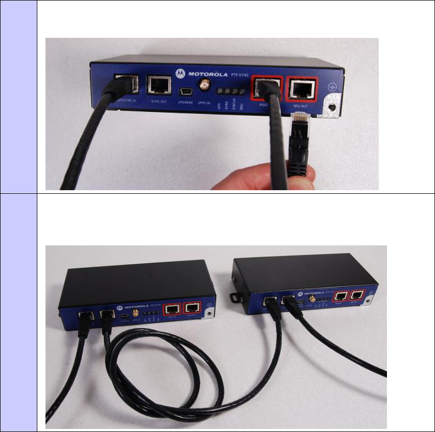
5 Use the supported Superior Essex cable (refer to Cables and connectors on
page 1-15) to connect the cable between the PTP-SYNC and the LPU or ODU.
6 This is a setup for clustered PTP-SYNC units (single GPS timing source with
multiple PTP-SYNC units or ODU systems). Use an un-screened CAT5e Ethernet
cable and connect the cable between PTP-SYNC units.
User Guide: PTP 600 Series Installing PTP-SYNC
phn-0896_009v003
Feb 2010 UNDER DEVELOPMENT 5-41
Power-up, testing and fault finding
The correct operation is as follows
• Ensure that all cables are connected to the correct interfaces of the PTP-SYNC
unit and the GPS receiver module. Failure to do so may result in damage to the
equipment.
• Connect mains power to the PIDU unit.
• Within 90 seconds the ’STATUS’ LED should blink once every second to show
that satellite lock has been achieved.
• If the system does not operate correctly, refer to the fault finding guide below.
Fault Finding Guide
LEDs do not illuminate
Ensure that there is a cable connection between the PIDU ‘ODU’ interface and the
‘PIDU IN’ interface of the PTP-SYNC unit.
A 1PPS synchronisation pulse does not appear to be detected by the PTP-
SYNC unit (no satellite lock)
Failure of the ‘STATUS’ LED to illuminate or blink.
Depending on configuration:
1) System using a GPS receiver module - Ensure that there is a cable connection
between the PTP-SYNC ‘GPS/SYNC IN’ interface and the LPU, also that there is a
cable connection between the LPU and the GPS receiver module. Check that the
GPS receiver module has an uninterrupted view of the sky.
2) System using an alternative 1PPS timing source - Ensure that there is a cable
connection between the PTP-SYNC ‘GPS/SYNC IN’ or ‘1PPS IN’ interface and the
1PPS timing source.
Installing PTP-SYNC Chapter 5 Installation
phn-0896_009v003
5-42 UNDER DEVELOPMENT Feb 2010
No communications between clustered PTP-SYNC units
Ensure that there is a cable connection between the ‘SYNC OUT’ interface of the first
PTP-SYNC unit and ‘GPS/SYNC IN’ interface of the second PTP-SYNC unit.
No communications between PTP-SYNC and ODU
Failure of the ‘ODU’ LED to illuminate within 90 seconds of power-up.
Ensure that there is a cable connection between the PTP-SYNC ‘ ODU OUT’ interface
and the either the ODU or the LPU unit leading to the ODU.
User Guide: PTP 600 Series Connecting the ODU, PIDU and LPUs
phn-0896_009v003
Feb 2010 UNDER DEVELOPMENT 5-43
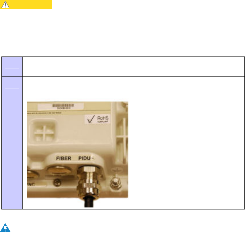
Connecting the ODU, PIDU and LPUs
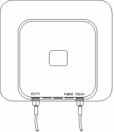
Locating the PIDU port on the ODU
Looking at the back of the unit with the cable entry at the bottom, the PIDU Plus
connection is the first hole on the right (Figure 5-16) and is labeled “PIDU +”.
Figure 5-16 ODU PIDU Plus connection
Connecting the ODU, PIDU and LPUs Chapter 5 Installation
phn-0896_009v003
5-44 UNDER DEVELOPMENT Feb 2010
Connecting the ODU to the PIDU cable
Perform this task to connect the ODU to the drop cable from the PIDU. It is often
easier to carry out this procedure on the ground or a suitable surface prior to
mounting the ODU.
CAUTION
To prevent damage to the ODU while making or breaking the connection,
ensure that power is removed from the system at the PIDU Plus.
To connect the PIDU Plus port of the ODU to the drop cable, proceed as follows:
Procedure 5-14 Connect the PIDU Plus to the ODU
1 Prepare the ODU end of the drop cable as described in Preparing the
supported Superior Essex cable on page 5-8.
2 Connect the cable gland of the drop cable to the PIDU Plus port of the ODU as
described in Connecting the drop cable to an ODU or LPU on page 5-16.
NOTE
If it is necessary to disconnect the drop cable from the ODU, refer to
Disconnecting the drop cable from an ODU or LPU on page 5-18.

User Guide: PTP 600 Series Connecting the ODU, PIDU and LPUs
phn-0896_009v003
Feb 2010 UNDER DEVELOPMENT 5-45
Routing the cable
After connecting the cable to the ODU it can be routed and secured using standard
cable routing and securing techniques. When the cable is in place it can then be cut to
the desired length at the PIDU Plus prior to connection to the PIDU Plus.
Fitting lightning protection units
Depending upon the chosen site configuation, it may be necessary to fit two or more
lightning protection units (LPUs). For more information, refer to Site installation
diagrams on page 2-26.
To mount an LPU and connect it to the input and output drop cables, proceed as
follows:
Procedure 5-15 Mount LPU and connect to GPS receiver
1 Check the contents of the LPU box (Figure 2-9 or Figure 2-10).
2 Mount the LPU (following manufacturer’s instructions) at the required point.
Mount the LPU vertically with cable glands facing downwards.
3 Prepare the input and output drop cable as described in Preparing the
supported Superior Essex cable on page 5-8.
4 Connect the cable gland of the input and output drop cable to the LPU as
described in Connecting the drop cable to an ODU or LPU on page 5-16.
NOTE
If it is necessary to disconnect a CAT5e cable from an LPU, refer to
Disconnecting the drop cable from an ODU or LPU on page 5-18.

Connecting the ODU, PIDU and LPUs Chapter 5 Installation
phn-0896_009v003
5-46 UNDER DEVELOPMENT Feb 2010
Grounding the installation
Install the equipment in accordance with Section 810 of the National Electric Code,
ANSI/NFPA No.70-1984 or Section 54 of the National Electrical Code in the country of
installation. These codes describe correct installation procedures for grounding the
outdoor unit, mast, lead-in wire and discharge unit, size of grounding conductors and
connection requirements for grounding electrodes. Motorola recommends that
installation of the outdoor unit be contracted to a professional installer.
Grounding the ODU
The Outdoor Unit (ODU) must be properly grounded to protect against power surges.
Additional grounding points
If the ODU is installed on a metal mast or tower, the screen of the supported Superior
Essex cable must be bonded to the tower at the top and bottom ends. Additional
grounding at intermediate points of the cable may be required if the cable is longer
than 15m (50 feet).
To ground the cable, follow the procedure described in Grounding the drop cable to a
metal tower or mast on page 5-11.
Connecting the PIDU to the ODU cable
Perform this task to connect the PIDU to the drop cable from the ODU.
The drop cable from the ODU is connected to the PIDU Plus by means of a concealed
RJ45 socket. The RJ45 socket has been placed inside the PIDU Plus hinged cover to
prevent the user from inadvertently plugging other equipment into the ODU RJ45
socket.
CAUTION
Plugging other equipment into the ODU RJ45 socket may damage the
equipment due to the non-standard techniques employed to inject DC power
into the 1000BaseT connection between the PIDU Plus and the ODU.
Plugging the ODU into other equipment may damage the ODU and/or the
other equipment.
To connect the PIDU Plus port of the ODU to the drop cable, proceed as follows:
User Guide: PTP 600 Series Connecting the ODU, PIDU and LPUs
phn-0896_009v003
Feb 2010 UNDER DEVELOPMENT 5-47
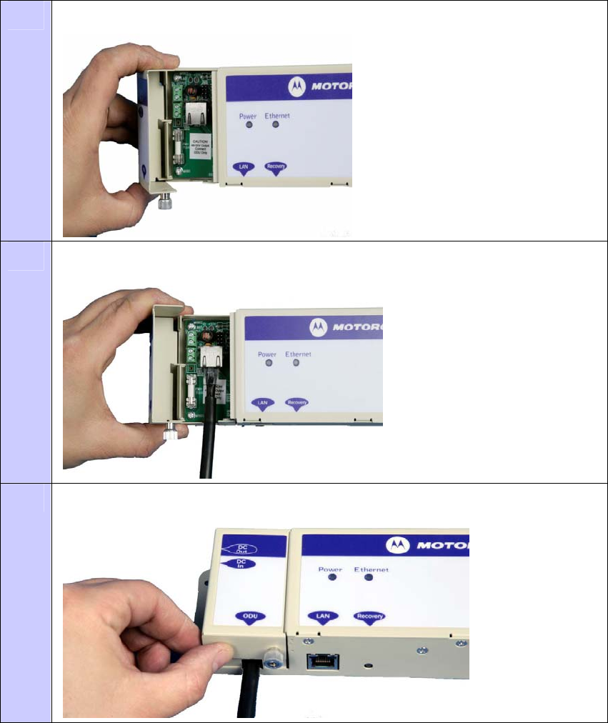
Procedure 5-16 Connecting the ODU to the PIDU Plus
1 Undo the retaining screw and hinge back the cover.
2 Plug in the ODU into the PIDU Plus Cable ensuring that it snaps home.
3 Replace the cover and secure with the retaining screw.
Connecting the ODU, PIDU and LPUs Chapter 5 Installation
phn-0896_009v003
5-48 UNDER DEVELOPMENT Feb 2010
Mounting the PIDU Plus
Mount the PIDU Plus on a wall or other suitable mounting surface, using the lugs
provided. This prevents the unit from being knocked or kicked and can help maintain
link availability. Ensure that the Recovery switch can be accessed when mounting the
unit.
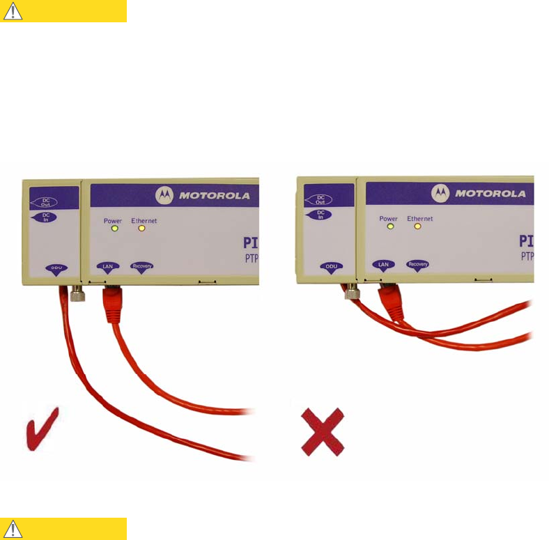
CAUTION
Do not dress the PIDU cables too tightly, as this may make the connections
unreliable. Figure 5-17 shoes the correct and incorrect ways to dress the
cables.
Figure 5-17 Correct and incorrect PIDU cable dressing
CAUTION
The PIDU Plus is not waterproof and should be mounted away from sources
of moisture. If mounted outdoors, the unit should be mounted in a rain proof
enclosure, preferably ventilated.
User Guide: PTP 600 Series Connecting the ODU, PIDU and LPUs
phn-0896_009v003
Feb 2010 UNDER DEVELOPMENT 5-49
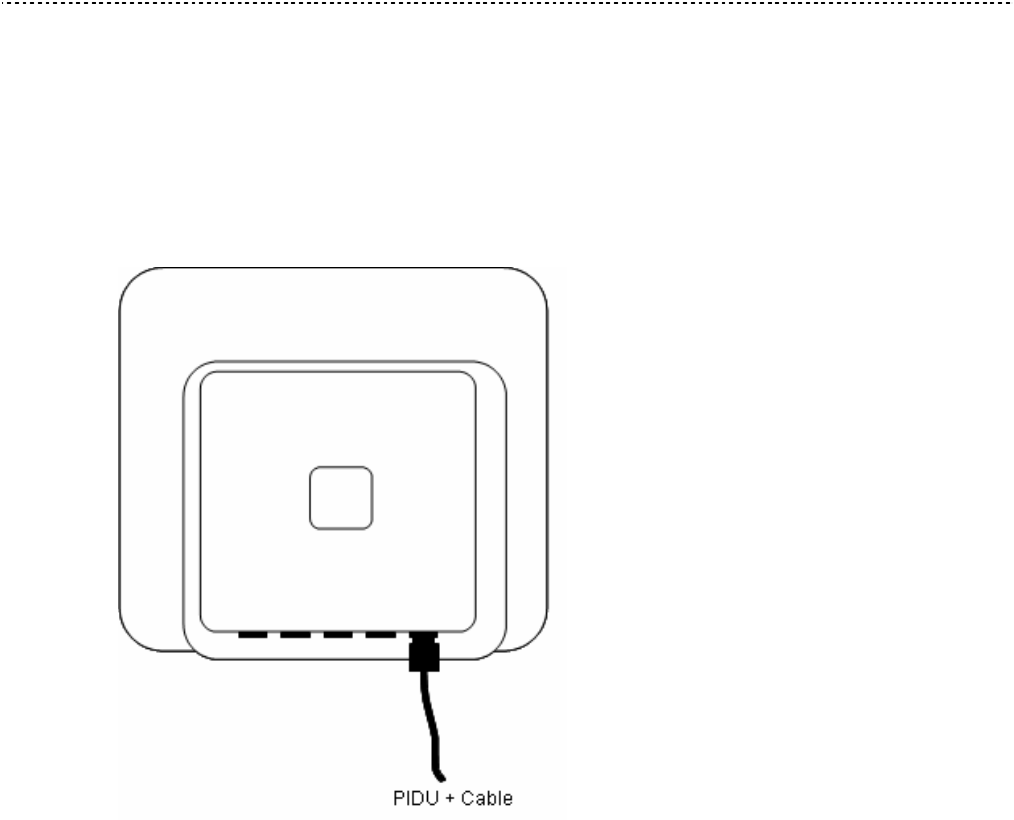
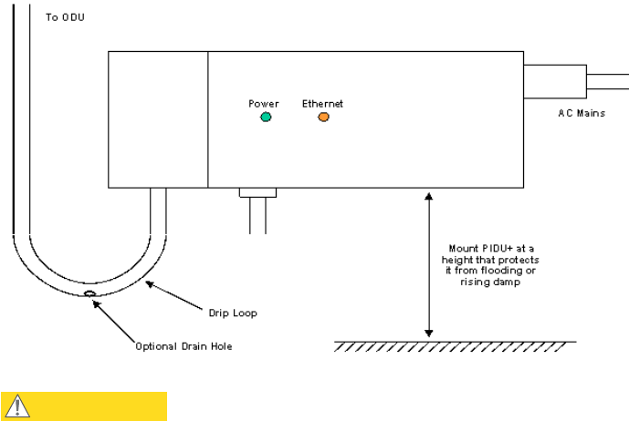
Drip loop
Fit a drip loop on the PIDU Plus to ODU cable to ensure that any moisture that runs
down the cable into the cabinet or enclosure cannot enter the PIDU Plus. This is shown
in Figure 5-18. The network connection and mains cable should be treated in the same
way if there is a risk that they can carry moisture to the PIDU Plus.
Figure 5-18 PIDU Plus drip loop configuration
CAUTION
It is possible for moisture to enter the cable due to damage to the outer
protective layer. This moisture can track down the inside of the cable, filling
up the drip loop and eventually finding its way into the PIDU Plus. To protect
against this the outer protective layer of the cable can be opened up at the
bottom of the drip loop to allow this moisture to escape.
Installing E1 and T1 Chapter 5 Installation
phn-0896_009v003
5-50 UNDER DEVELOPMENT Feb 2010
Installing E1 and T1
This section describes the installation and configuration of the E1/T1 interface.
NOTE
The maximum cable length between the ODU and the customers terminating
equipment is 200m (656 feet) for E1/T1.
E1/T1 connection diagrams
The E1/T1 cable should be assembled as described in Cables and connectors on page
1-15. This procedure applies to the ODU termination, but it must be repeated for the
customer equipment end of the cable when the cable is terminated with an RJ45.
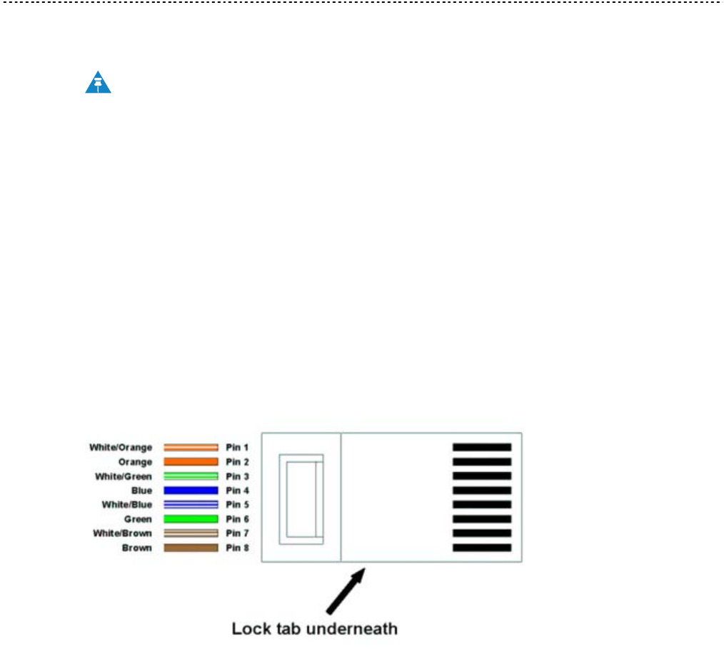
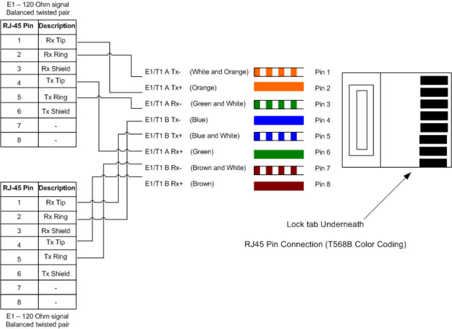
T568B color coding
The T568B color coding used in RJ45 E1/T1 cables is illustrated in Figure 5-19 and
Figure 5-20. The telecoms connection pin outs are specified in Table 5-2.
Figure 5-19 RJ45 pin connection (T568B color coding)
User Guide: PTP 600 Series Installing E1 and T1
phn-0896_009v003
Feb 2010 UNDER DEVELOPMENT 5-51
Figure 5-20 Cable connection diagram (T568B color coding)
Table 5-2 Telecoms connection pin out
Telecoms Connector Pinout Signal Name
Pin 1 E1T1A_TX-
Pin 2 E1T1A_TX+
Pin 3 E1T1A_RX-
Pin 4 E1T1B_TX-
Pin 5 E1T1B_TX+
Pin 6 E1T1A_RX+
Pin 7 E1T1B_RX-
Pin 8 E1T1B_RX+
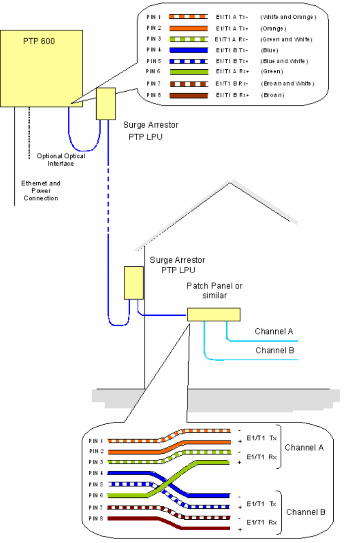
Connections at the ODU and patch panel
The E1/T1 connections at the ODU and patch panel are illustrated in Figure 5-21.
Installing E1 and T1 Chapter 5 Installation
phn-0896_009v003
5-52 UNDER DEVELOPMENT Feb 2010
Figure 5-21 E1-T1 connections at the ODU and patch panel
Installing E1 and T1 Chapter 5 Installation
phn-0896_009v003
5-54 UNDER DEVELOPMENT Feb 2010
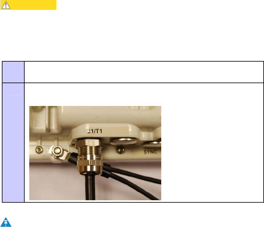
Locating the E1/T1 port on the ODU
Looking at the back of the unit with the cable entry at the bottom, the PTP 600 Series
E1/T1 connection is the first hole on the left (Figure 5-23) and is labeled E1/T1.
Figure 5-23 PIDU Plus and E1/T1 connection
User Guide: PTP 600 Series Installing E1 and T1
phn-0896_009v003
Feb 2010 UNDER DEVELOPMENT 5-55
Connecting the ODU to the E1/T1 cable
Perform this task to connect the ODU to the E1/T1 cable. It is often easier to carry out
this procedure on the ground or a suitable surface prior to mounting the ODU.
CAUTION
To prevent damage to the ODU while making or breaking the connection,
ensure that power is removed from the system at the PIDU Plus.
To connect the E1/T1 port of the ODU to the E1/T1 cable, proceed as follows:
Procedure 5-17 Connect the E1/T1 cable to the ODU
1 Prepare the ODU end of the E1/T1 cable as described in Preparing the
supported Superior Essex cable on page 5-8.
2 Connect the cable gland of the E1/T1 cable to the E1/T1 port of the ODU as
described in Connecting the drop cable to an ODU or LPU on page 5-16.
NOTE
If it is necessary to disconnect the E1/T1 cable from the ODU, refer to
Disconnecting the drop cable from an ODU or LPU on page 5-18.
Installing E1 and T1 Chapter 5 Installation
phn-0896_009v003
5-56 UNDER DEVELOPMENT Feb 2010
Routing the cable
After connecting the cable to the ODU it can be routed and secured using standard
cable routing and securing techniques. When the cable is in place it can then be cut to
the desired length.
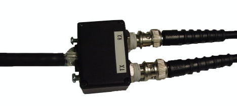
Customer cable termination
The two channels can be separated by means of a patch panel which may include
Baluns for transmission over 75 Ohm co-axial unbalanced lines. Such equipment
should conform to the requirements of C.C.I.T.T. G703. An example of a Balun is
shown below. It allows the transmit and receive data carried over a 75 Ohm cable to
be converted to a balanced form for transmission over a 120 Ohm signal balanced
twisted pair.
Figure 5-24 Example of a Balun

User Guide: PTP 600 Series Installing E1 and T1
phn-0896_009v003
Feb 2010 UNDER DEVELOPMENT 5-57
Lightning protection and E1/T1
Lightning protection on page 2-18 contains the basic requirements for the Motorola
PTP 600 Series deployment. For E1/T1, an extra grounding cable is supplied to
connect the other PTP-LPU to the ODU ground. This section details the additional
requirements for the deployment of E1/T1.
Recommended components for E1/T1 installation
For a description of Zone A and Zone B refer to Lightning protection zones on page 2-
19.
Table 5-3 Protection requirements
Component Zone A Zone B
Earth ODU Mandatory Mandatory
Screen Cable Mandatory Mandatory
Lightning Protection Unit PTP LPU at ODU Mandatory Mandatory
Earth Cable at Building Entry Mandatory Mandatory
Lightning Protection Unit PTP LPU at Building
Entry
Mandatory Mandatory
Refer to Site installation diagrams on page 2-26 to see how the components of PTP 600
sites with E1/T1 are installed and connected. This section also lists the recommended
components for each type of installation.

Installing E1 and T1 Chapter 5 Installation
phn-0896_009v003
5-58 UNDER DEVELOPMENT Feb 2010
Testing the E1/T1 installation
If you have opted to fit a Lightning Protection Unit, it should be tested as described in
LPU installation wiring on page 2-24.
Test the telecoms links by performing loopback connections as described in
Configuring the telecoms circuits on page 6-49.
Pre-power testing
Before connecting your E1/T1 source, check the following resistances:
• Check the cable resistance between pins 3 & 6 (Green/White & Green) and 7 & 8
(Brown/White & Brown). Check against Table 5-4 column 2.
• Check the cable resistance between pins 1 & 2 (Orange/White & Orange) and 4 &
5 (Blue & Blue/White). Check against Table 5-4 column 3.
Table 5-4 Resistance referenced to the E1/T1 source
CAT-5 Length (Meters) Resistance between pins
3 & 6 and pins 7 & 8
(ohms)
Resistance between pins
1 & 2 and pins 4 & 5
(ohms)
0 0.8 1.3
10 2.5 3.0
20 4.2 4.7
30 5.9 6.4
40 7.6 8.2
50 9.3 9.8
60 11.0 11.5
70 12.7 13.2
80 14.4 14.9
90 16.1 18.2
100 17.8 18.3

User Guide: PTP 600 Series Establishing a radio link
phn-0896_009v003
Feb 2010 UNDER DEVELOPMENT 5-59
Establishing a radio link
This section describes how to establish a radio link between the two units forming the
bridge and align the units for the best signal strength.
Before performing these tasks, connect the PIDU Plus to the network, power up the
unit and open the web interface. For more information, refer to:
• Powering up and connecting the PIDU Plus on page 5-3.
• Opening the web interface on page 5-4.
Using the ODU installation tones
The PTP 600 ODU emits audible tones during installation to assist with alignment. The
pitch of the alignment tone is proportional to the received power of the wireless
signals. Adjust the alignment of the unit in both azimuth and elevation until the
highest pitch tone is achieved. The tones and their meanings are described in Table
5-5. In each of the states detailed in the table, align the unit to give the highest pitch
tone.
Table 5-5 ODU installation tones
State Name Tone Description State Description Pitch Indication
Free Channel
Search
Regular beep Executing band scan N/A
Scanning Slow broken tone Not demodulating the
wanted signal
Rx Power
Synchronized Fast broken tone Demodulating the wanted
signal
Rx Power
Registered Solid tone Both Master and Slave
units exchanging Radio
layer MAC management
messages
Rx Power
Alarm Fast broken dual
tone
A fatal error has
occurred.
The term ‘wanted signal’ refers to that of the peer unit being installed.

Establishing a radio link Chapter 5 Installation
phn-0896_009v003
5-60 UNDER DEVELOPMENT Feb 2010
CAUTION
If, when in the Synchronized or Registered state, the tone varies wildly,
there may be interference or a fast fading link. Installing in this situation
may not give a reliable link. Investigate the cause of the problem.
Aligning the units
To align the units, proceed as follows:
Procedure 5-18 Align Master and Slave
1 Adjust the elevation and azimuth of the Master unit to achieve an approximate
visual alignment with the site of the Slave unit.
2 Adjust the elevation and azimuth of the Slave unit to achieve an approximate
visual alignment with the site of the Master unit.
3 Without moving the Master unit, adjust the elevation and azimuth of the Slave
unit to achieve the highest pitch installation tone.
4 Without moving the Slave unit, adjust the elevation and azimuth of the Master
unit to achieve the highest pitch installation tone.
5 Repeat steps 3 and 4 as necessary to fine tune the alignment.
NOTE
To achieve best results, make small incremental changes to elevation and
azimuth.
There is a graphical installation screen (see Graphical install on page 6-75) available in
the web interface that displays the state of the link during the alignment process (up =
green, down = red).
User Guide: PTP 600 Series Establishing a radio link
phn-0896_009v003
Feb 2010 UNDER DEVELOPMENT 5-61
Behaviour during alignment
When the units are powered up and alignment begins, the following behavior may be
observed:
Band scan
When first started up and from time to time, the Master unit will carry out a band scan
to determine which channels are not in use. During this time, between 10 and 15
seconds, the Master unit will not transmit and as a consequence of this neither will the
Slave unit. During this time the installation tone on the master unit will drop back to
the band scan state, and the Slave unit will drop back to the Scanning state with the
pitch of the tone set to the background noise level. Alignment of the unit should cease
during this time.
Radar detection
If the unit is operating where mandatory radar avoidance algorithms are implemented,
the ranging behaviour for the PTP 600 Series may be affected. The Master has to
monitor the initially chosen channel for 60 seconds to make sure it is clear of radar
signals before transmitting. If a radar is detected during any of the installation phases,
a further compulsory 60 seconds channel scan will take place as the master unit
attempts to locate a new channel that is free of radar interference.
Ranging
The Master unit can take up to 60 seconds in 0-40 km (0-25 miles) mode, 90 seconds in
0-130 km (0-81 miles) mode and 120 seconds in 0-200 km (0-124 miles) mode to
determine the range of the link being installed. The Master unit will remain in the
Scanning state until the range of the link has been established. The Master unit will
only move to the Synchronized state when the range of the link has been established.
The Slave unit does not have a ranging process. The slave unit will change to the
Synchronized state as soon as the wanted signal is demodulated.

Establishing a radio link Chapter 5 Installation
phn-0896_009v003
5-62 UNDER DEVELOPMENT Feb 2010
Retrying same channel
If, at the end of the ranging period, the Registered state is not achieved due to
interference or other reasons, the Master unit will retry twice more on the same
channel before moving to another available channel. Should this occur it might take a
number of minutes to establish a link in the Registered state.
Adjusting power settings
The transmit power levels of the installed units must be adjusted to ensure they are
not too high. Excessive power levels may cause saturation of the receivers or false
radar detection (in radar enabled regions), leading to degradation of link performance
and link failure.
To adjust power levels, proceed as follows:
Procedure 5-19 Adjust power levels
1 Consult the report generated by the LINKPlanner tool and note the Transmit
power recommended levels.
2 Set the local unit power equal to the “LOCAL - Max Transmit Power setting
while pointing” value from the LINKPlanner report.
3 Set the remote unit power equal to the “REMOTE - Max Transmit Power setting
while pointing” value from the LINKPlanner report.
4 Access each unit separately.
5 Align the units.
6 Repeat Step 2 and 3 using the values “LOCAL - Max Transmit Power setting
before disarm” and “REMOTE - Max Transmit Power setting before disarm” , if
different than the corresponding “while pointing” values.
7 Reboot the local unit then reboot the remote unit.
8 Disarm the units.

User Guide: PTP 600 Series Establishing a radio link
phn-0896_009v003
Feb 2010 UNDER DEVELOPMENT 5-63
Disarm on completion
When the alignment process is complete, disarm both units in the link, as described in
Installation pages on page 6-51. This is necessary in order to:
• Turn off the audible alignment aid (see Disarm installationon page 6-72)
• Enable Adaptive Modulation
• Fully enable Advanced Spectrum Management with i-DFS
• Clear unwanted installation information from the various systems statistics
• Store the link range for fast link acquisition on link drop
• Enable higher data rates
NOTE
After 24 hours, the units will be disarmed automatically, provided that they
are armed and that the link is up.

Chapter 6
phn-0896_009v003
Feb 2010 UNDER DEVELOPMENT 6-1
Chapter 6 Operation
. . . . . . . . . . . . . . . . . . . . . . . . . . . . . . . . . . . . . . . . . . . . . . . . . . . . . . . . . . . .
.
.
.
.
This chapter describes the PTP 600 web user interface and provides instructions for
operators.
The following topics are described in this chapter:
• Web-based management on page 6-2
• Configuring the PTP 600 on page 6-19
• Installation pages on page 6-51
• Upgrading the PTP 600 on page 6-77
• Managing security on page 6-90
• Managing faults on page 6-112
• Managing performance on page 6-119
• Properties on page 6-131
• Reboot on page 6-132
NOTE
The web pages are best viewed using a screen resolution of at least 1024 x
768 pixels on a PC using Microsoft Internet Explorer Version 6 or 7.
The web pages have also been tested with Firefox 2.0.0.12. Other browsers
have not been tested.

Web-based management Chapter 6 Operation
phn-0896_009v003
6-2 UNDER DEVELOPMENT Feb 2010
Web-based management
Menu navigation bar
The navigation bar on the left hand side of the web page is used to move between the
various management pages. The currently selected page is always highlighted with a
light blue background. The menu is hierarchical. Selecting a menu item which has
associated submenu options will automatically display all sub options. A sample web
page with the navigation menu is shown in Figure 6-1.
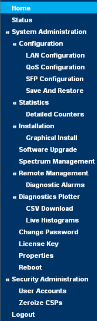
User Guide: PTP 600 Series Web-based management
phn-0896_009v003
Feb 2010 UNDER DEVELOPMENT 6-3
Figure 6-1 Menu navigation bar
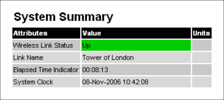
Web-based management Chapter 6 Operation
phn-0896_009v003
6-4 UNDER DEVELOPMENT Feb 2010
The web user interface menu has three main options.
• Home: This presents to the operator a high level summary of the PTP 600 Series
point-to-point wireless link.
• Status: This presents a more detailed set of system parameters describing the
performance of the wireless link together with other key system performance
metrics.
• System Administration: This section is password protected and allows the
system administrator to perform all the day-to-day administrative procedures, for
example software upgrade and configuration changes.
Home (system summary)
The home page for the PTP 600 Series (Figure 6-2) displays a high level summary of
the status of the wireless link and associated equipment.
Figure 6-2 System Summary page
The home page normally displays four key system attributes:
Wireless Link Status
The Wireless Link Status attribute displays the current status of the PTP 600 Series
wireless link. A state of ‘Up’ on a green background indicates that a point-to-point link
is established. A state of ‘Down’ on a red background indicates that the wireless link is
not established. If the link is down for an unknown reason the system administrator
should first consult the status web page for a more detailed summary of up to date
system diagnostics.
User Guide: PTP 600 Series Web-based management
phn-0896_009v003
Feb 2010 UNDER DEVELOPMENT 6-5
Link Name
The link name attribute is a name and/or handle allocated by the system administrator
to aid the identification of the unit, network or building.
Elapsed Time Indicator
The elapsed time indicator attribute presents the total time in days, hours, minutes
and seconds since the last system restart. The system can restart for several reasons,
for example, commanded reboot from the system reboot webpage, or a power cycle of
the equipment.
System Clock
If SNTP (Simple Network Time Protocol) is enabled, or the clock has been set, then a
system clock attribute is displayed giving the date and time of the last page refresh.
Section SNTP (Simple Network Time Protocol) on page 6-117 explains how to enable
SNTP and Section Setting the clock on page 6-118 explains how to set the clock.
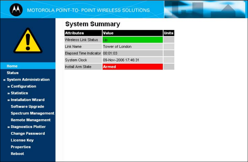
Web-based management Chapter 6 Operation
phn-0896_009v003
6-6 UNDER DEVELOPMENT Feb 2010
Home page alarm display
The home page is also used to display all outstanding major system alarms. Whenever
system alarms are asserted, a yellow warning triangle is displayed on web page
navigation bar. The warning triangle will be visible from all web pages. Clicking the
warning triangle will cause the web page to jump back to the system homepage.
Figure 6-3 shows a sample alarm screen.
Figure 6-3 Alarm warning triangle
User Guide: PTP 600 Series Web-based management
phn-0896_009v003
Feb 2010 UNDER DEVELOPMENT 6-7
System alarms
The following system alarms are defined:
Region code
The region code prohibits the wireless unit from operating outside the regulated
limits. An invalid region code indicates a corrupted license key. Note that a change of
state may generate an SNMP trap and/or SMTP email alert.
Install Status
A non-OK value indicates that signaling was received with the wrong MAC address.
Note that it is very unusual to detect this, because units with wrongly configured
Target MAC Address will normally fail to establish a wireless link. However, rare
circumstances may establish a partial wireless link and detect this situation. NB: A
non-OK value on start-up, or a change of value during operation, may generate an
SNMP trap and/or SMTP email alert.
Install Arm State
This alarm warns when a wireless unit is in installation mode. After installation the
wireless unit should be disarmed. This will increase the wireless link’s data-carrying
capacity and stop the installation tone generator. The wireless link is disarmed from
the ‘Installation’ process see Disarm installation on page 6-72. A change of state may
generate an SNMP trap and/or SMTP email alert.
Unit Out Of Calibration
The unit is out of calibration and must be returned to the factory using the RMA
process for re-calibration.
Incompatible Region Codes
The PTP 600 Series uses region codes to comply with local regulatory requirements
governing the transmission of wireless signals in the frequency bands in which it
operates. Region codes can only be changed by obtaining a new PTP 600 Series license
key. If this alarm is encountered, the appropriate license keys from the country of
operation should be obtained from your distributor. Applying license keys containing
the same region codes to both ends of the link will remove the alarm. A change of state
may generate an SNMP trap and/or SMTP email alert.
Web-based management Chapter 6 Operation
phn-0896_009v003
6-8 UNDER DEVELOPMENT Feb 2010
Incompatible Master and Slave
A non-zero value indicates that the master and slave ends of the wireless link are
different hardware products, or have different software versions. Note that it is very
unusual to detect this because incompatible units will normally fail to establish a
wireless link. However, some combinations may establish a partial wireless link and
detect this situation. Note that a non-zero value may generate an SNMP trap and/or
SMTP email alert.
Ethernet Configuration Mismatch
The detection of Ethernet fragments (runt packets) when the link is in full duplex is an
indication of an auto-negotiation or forced configuration mismatch. Note that a change
of state may generate an SNMP trap and/or SMTP email alert.
No Wireless Channel Available
Spectrum Management was unable to locate a suitable wireless channel to operate on.
Note that a change of state may generate an SNMP trap and/or SMTP email alert.
SNTP Synchronization failed
This warning indicates that SNTP has been enabled but that the unit is unable to
synchronize with the specified SNTP server. Section SNTP (Simple Network Time
Protocol) on page 6-117 explains how to configure SNTP. Note that a change of state
may generate an SNMP trap and/or SMTP email alert.
Wireless Link Disabled Warning
This warning is displayed if the Wireless link has been administratively disabled via
the SNMP Interface (see Managing faults on page 6-112). The Wireless Interface MIB-
II ifAdminStatus attribute has been set to DOWN. To enable the Ethernet interface, set
the ifAdminStatus attribute to UP. Note that a change of state may generate an SNMP
trap and/or SMTP email alert.
Ethernet Link Disabled Warning
This warning is displayed if the Ethernet link has been administratively disabled via
the SNMP Interface (see Managing faults on page 6-112). The Ethernet Interface MIB-
II ifAdminStatus attribute has been set to DOWN. To enable the Ethernet interface, set
the ifAdminStatus attribute to UP. Note that a change of state may generate an SNMP
trap and/or SMTP email alert.
Ethernet Link Status
Current status of the Ethernet link. If there are any problems with the Ethernet
interface, this alarm will be asserted. This alarm will most likely be seen if the unit has
no Ethernet cable plugged into its Ethernet socket. Note that a change of state may
generate an SNMP trap and/or SMTP email alert.

User Guide: PTP 600 Series Web-based management
phn-0896_009v003
Feb 2010 UNDER DEVELOPMENT 6-9
Fiber Link Status
If the fiber link is not OK, there are two possible causes: Either the fiber link has been
installed but disabled (because the license key does not include fiber support), or the
link could not be established even though an optical carrier was detected (due perhaps
to a broken TX fiber, or the link is disabled at the fiber link partner). Note that a
change of status may generate an SNMP trap and/or SMTP email alert.
Telecoms Channel A/B Status
Indicates one of the following alarm conditions on a telecoms channel:
Alarm Condition Meaning
No Signal (Local) There is no telecoms signal present at the connection to
the ODU at the local end.
No Signal (Remote) There is an absence of telecoms data across the wireless
link.
No Signal (Local and
Remote)
The above two alarm conditions occur concurrently.
Remote Timing There is insufficient wireless capacity available to carry
telecoms data. Under these conditions telecoms timing
information is still sent to keep the telecoms clocks
synchronized.
No Signal (Local)
and Remote Timing
Indicates both no local signal and remote timing.
In remote timing mode the ODU will transmit an Alarm Indication Signal (AIS),
consisting of all-ones, from the associated telecoms interface. A change of state may
generate an SNMP trap and/or SMTP email alert.
See Telecoms interface on page 6-57 for a description of the Telecoms Interface.
Telecoms Channel A/B Loopback
The loopback status of telecoms channel A and B. These are intended for installation
testing and should be set to 'None' for normal operation. The wire connections to a
unit can be tested by applying a 'Copper' loopback to the local unit. The wireless
connection to the remote unit can be tested by applying a 'Wireless' loopback to the
remote unit with no loopback on the local unit.
A change of state may generate an SNMP trap and/or SMTP email alert. The loopback
can be disabled from the telecoms configuration sub menu (see Configuring the
telecoms circuits on page 6-49).
See Telecoms interface on page 6-57 for a description of the Telecoms Interface.
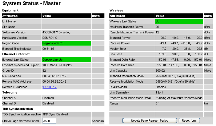
Web-based management Chapter 6 Operation
phn-0896_009v003
6-10 UNDER DEVELOPMENT Feb 2010
TDD Synchronization Alarm
Indicates the current status of the TDD Synchronization (OK, Timing System Failure,
Not Synchronized). Note that a change of state may generate an SNMP trap and/or
SMTP email alert.
Link Mode Optimization Mismatch
The Master and Slave ODUs are configured to use different link mode optimization
methods (one is set to IP and the other TDM).
System status
The status page (Figure 6-4) gives the system administrator a detailed view of the
operation of the PTP 600 Series from both the wireless and network perspectives.
Figure 6-4 System Status page
The page is subdivided into five categories:
• Equipment: This contains the unit’s inventory and identification information.
• Wireless: This presents the key wireless metrics, which are displayed as a series
of measurements.
• Ethernet/Internet: This describes the unit’s network identity and connectivity.
• Telecoms: This describes the unit’s E1/T1 telecoms interface parameters.
• TDD Synchronization: This shows the status of TDD synchronization.

User Guide: PTP 600 Series Web-based management
phn-0896_009v003
Feb 2010 UNDER DEVELOPMENT 6-11
The status page can be configured to refresh itself at an operator defined rate (if the
user is logged in as system administrator). The refresh period defaults to 3600 seconds
and can easily be changed to refresh at any period between 2 seconds and 3600
seconds. Pressing the ‘Update Page Refresh Period’ button causes a new page refresh
period to be adopted by the system. The page refresh mechanism uses a HTML Meta
refresh command. Therefore the refresh is always initiated by the local browser and
not by the PTP 600 Series at this interval.
The two PTP 600 Series units are arranged in a master and slave relationship. The
roles of the units in this relationship are displayed in the page title. The master unit
will always have the title ‘- Master’, and the slave will always have ‘- Slave’ appended
to the ‘Systems Status’ page title.
The following attributes are displayed on the status page:
Link Name
The link name is allocated by the system administrator and is used to identify the
equipment on the network. The link name attribute is limited to a maximum size of 63
ASCII characters.
Site Name
The site name is allocated by the system administrator and can be used as a generic
scratch pad to describe the location of the equipment or any other equipment related
notes. The site name attribute is limited to a maximum size of 63 ASCII characters.
Software Version
The attribute describes the version of software installed on the equipment. The format
of the attributes is
FFSSS
-XX-
YY
where
FF
is the frequency variant (2.5, 4.5, 5.4, 5.8
or 5.9 GHz),
SSS
is the System Release,
XX
is the major release version and
YY
is the
minor release version.
Hardware Version
The hardware version attribute contains all the combined hardware version
information. The attribute is formatted as D
XX
-R
YY
-
Z
where D
XX
contain the version
of the digital card, R
YY
contains the version of the RF (radio frequency) card and
Z
describes the antenna type which can be I (integrated) or C (connectorized).
Region Code
The region code is used by the system to constrain the wireless to operate within
regulatory regime of the particular country. The region code is encoded in the product
license key. If the operator wishes to change region code, a new license key must be
obtained from Motorola or the local point-to-point distributor or system integrator.
Web-based management Chapter 6 Operation
phn-0896_009v003
6-12 UNDER DEVELOPMENT Feb 2010
Elapsed Time Indicator
The elapsed time indicator attribute presents the total time in years, days, hours,
minutes and seconds since the last system restart. The system can restart for several
reasons, for example commanded reboot from the system reboot web page, or a power
cycle of the equipment.
Ethernet Link Status:
This indicates the current status of the Ethernet link. A state of ‘Up’ with a green
background indicates that an Ethernet link is established. A state of ‘Down’ with a red
background indicates that the Ethernet link is not established.
Ethernet Speed and Duplex
The negotiated speed and duplex setting of the Ethernet interface. The speed setting is
specified in Mbps.
Full Duplex data transmission means that data can be transmitted in both directions
on a signal carrier at the same time. For example, on a local area network with a
technology that has full duplex transmission; one workstation can be sending data on
the line while another workstation is receiving data.
Half Duplex data transmission means that data can be transmitted in both directions
on a signal carrier, but not at the same time. For example, on a local area network
using a technology that has half duplex transmission, one workstation can send data
on the line and then immediately receive data on the line from the same direction in
which data was just transmitted.
Remote IP Address
Hyperlink to the other side of the Link. The IP address of the peer link is displayed if
the Link is UP, otherwise “unavailable” is displayed.
Telecoms Channel A and B
Indicate the current status of the telecoms channels. Channels which are disabled
during installation are marked as such. Correctly operating channels display "Up" on a
green background, but alarm conditions (described in Section Home page alarm
display on page 6-6) have a red background.
The Telecoms Latency value, displayed in microseconds, is determined when the
wireless link starts and will remain the same for a given wireless configuration.
Section Telecoms circuits on page 1-36 describes methods for reducing telecoms
latency on links which support high data rate modulation modes.
User Guide: PTP 600 Series Web-based management
phn-0896_009v003
Feb 2010 UNDER DEVELOPMENT 6-13
Under normal circumstances the unit will freely transition between modulation modes
to suit the wireless conditions. The "Single Payload Lock" indicates that the ODU will
prevent transitions from Single Payload modes to the higher Dual Payload modes in
order to avoid loss of telecoms data. This field appears where such a transition would
pass through modes which cannot carry telecoms data. This may be because, in order
to control latency, the lowest modulation mode has been set to a higher Single Payload
mode.
In the absence of the Single Payload Lock the wireless will transition to the faster Dual
Payload modes as soon as the conditions are appropriate. With the lock enabled, the
wireless will dwell in slower Single Payload modes whenever there are operational
telecoms links (operational links are shown as "Up" in the telecoms channel field
described above). When the lock is actively preventing transitions, the value displayed
changes from "Enabled" to "Applied".
TDD Synchronization
Displays the TDD Synchronization status for the link. For more information, refer to
TDD synchronization status on page 6-16.
Refresh Page Period
The Status page refreshes automatically according to the setting entered here (in
seconds). This attribute is only displayed when the user is logged on as System
Administrator.
Wireless Link Status
As the attribute name suggests it displays the current status of the wireless link. A
state of ‘Up’ on a green background indicates that a point-to-point link is established.
A state of ‘Down’ on a red background indicates that the wireless link is not
established.
Maximum Transmit Power
The maximum transmit power that the local wireless unit is permitted to use to sustain
a link.
Remote Maximum Transmit Power
The maximum transmit power that the remote wireless unit is permitted to use to
sustain a link.
Transmit Power
Transmit power histogram is expressed in dBm and presented as: max, mean, min, and
latest. The max, min and latest are true instantaneous measurements; the mean is the
mean of a set of one second means. See Histogram data on page 6-18.
Web-based management Chapter 6 Operation
phn-0896_009v003
6-14 UNDER DEVELOPMENT Feb 2010
Receive Power
Receive power histogram is expressed in dBm and presented as: max, mean, min, and
latest. The max, min and latest are true instantaneous measurements; the mean is the
mean of a set of one second means. See Histogram data on page 6-18.
Vector Error
The vector error measurement compares the received signal’s In phase / Quadrature
(IQ) modulation characteristics to an ideal signal to determine the composite error
vector magnitude. The results are stored in an histogram and expressed in dB and
presented as: max, mean, min and latest. The max, min and latest are true
instantaneous measurements; the mean is the mean of a set of one second means. The
expected range for Vector Error would be approximately -2dB (NLOS link operating at
sensitivity limit on BPSK 0.67) to –33dB (short LOS link running 256 QAM 0.83). See
Histogram data on page 6-18.
Link Loss
The link loss is the total attenuation of the wireless signal between the two
point-to-point units. See Histogram data on page 6-18.
The link loss calculation presented below:
Equation 6-1 Link loss
xxxx RTRTll ggPPP ++−=
Where is
ll
P Link Loss (dB)
x
T
P
Transmit power of the remote wireless
unit (dBm)
x
R
P
Received signal power at the local unit
(dBm)
xx RT gg ,
Antenna gain at the remote and local
units respectively (dBi). The antenna
gain of the PTP 600 Series (23.5 dBi)
is used unless one or both of the units
is a Connectorized version.

User Guide: PTP 600 Series Web-based management
phn-0896_009v003
Feb 2010 UNDER DEVELOPMENT 6-15
Transmit Data Rate
The data rate in the transmit direction, expressed in Mbps and presented as: max,
mean, min, and latest in an histogram format. The max, min and latest are true
instantaneous measurements; the mean is the mean of a set of one second means.
Expected data rates can be found in Data rate calculations on page 4-99.
Receive Data Rate
The data rate in the receive direction, expressed in Mbps and presented as: max,
mean, min, and latest in an histogram format. The max, min and latest are true
instantaneous measurements; the mean is the mean of a set of one second means.
Expected data rates can be found in Data rate calculations on page 4-99.
Link Capacity
The maximum aggregate data rate capacity available for user traffic, assuming the
units have been connected using Gigabit Ethernet. The link capacity is variable and
depends of the prevailing wireless conditions as well as the distance (range) between
the two wireless units.
Transmit Modulation Mode
The modulation mode currently being used on the transmit channel. A list of all the
modulation modes can be found in Data rate calculations on page 4-99, where data
rate calculations plots are given for each available modulation mode.
Receive Modulation Mode
The modulation mode currently being used on the receive channel. A list of all the
modulation modes can be found in Data rate calculations on page 4-99, where data
rate calculations plots are given for each available modulation mode.
Link Symmetry
A ratio that expresses the division between transmit and receive time in the TDD
frame. The first number in the ratio represents the time allowed for the transmit
direction and the second number represents the time allowed for the receive direction.
NOTE
Link Symmetry is configured at the master ODU only. The appropriate
matching Link Symmetry is set at the slave ODU automatically. For example,
if Link Symmetry is configured as “2 to 1” at the master ODU, then the slave
ODU will be set automatically as “1 to 2”. In this example, the master-slave
direction has double the capacity of the slave-master direction.
Web-based management Chapter 6 Operation
phn-0896_009v003
6-16 UNDER DEVELOPMENT Feb 2010
Receive Modulation Mode Detail
This supplies the user with information regarding the receive modulation mode in use.
Possible values are:
• “Running at maximum receive mode”
• “Running at user-configured Max Modulation Mode”
• “Restricted due to byte errors on the wireless link or local Ethernet Tx Fifo
Drops”
• “Restricted because a DFS channel change is in progress”
• “Restricted due to telecoms acquisition mode”
• “Restricted due to the low Ethernet link speed”
• “Limited by the wireless conditions”
Range
The range between the PTP 600 Series ODUs. This is displayed in km by default, but
can be changed to miles by updating the ‘Distance Units’ attribute to imperial, as
described in Properties on page 6-131.
TDD synchronization status
The Status Page displays the TDD Synchronization status for the link.
If TDD Synchronization is not enabled, the Attribute is set to “TDD Synchronization
Inactive” and the Value is set to “Timing System Not Connected”.
If TDD Synchronization is enabled and the installation is rebooted, the Attribute is set
to “TDD Synchronization Status” and the Value is set to one of the following:
• Locked: (Figure 6-5)
• Holdover:
• Holdover (Not Connected)
• Acquiring Lock
• No Timing Reference
• Timing System Not Connected (Figure 6-6)
• Initialising
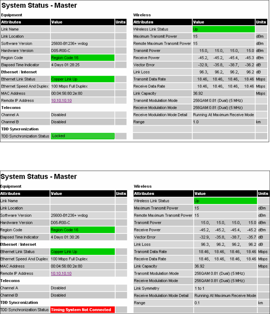
User Guide: PTP 600 Series Web-based management
phn-0896_009v003
Feb 2010 UNDER DEVELOPMENT 6-17
Figure 6-5 Status page - TDD enabled and synchronized
Figure 6-6 Status page - TDD enabled and not synchronized

Web-based management Chapter 6 Operation
phn-0896_009v003
6-18 UNDER DEVELOPMENT Feb 2010
Histogram data
The histogram is calculated over a one hour period. If the equipment has been running
for less than one hour, then the histogram is calculated over the current elapsed time.
The data used to compute the histogram statistics can be downloaded in an ASCII
comma separated value (CSV) format via the diagnostics CSV Download page, see CSV
download on page 6-130.
System administration
Figure 6-7 shows the system administration login page. By default a system
administrator password is not set.
Figure 6-7 System administration login page
The menu options that are available to the system administrator are:
• Configuration
• Statistics
• Installation
• Software Upgrade
• Spectrum Management
• Remote management
• Diagnostics Plotter
• Change Password
• License Key
• Properties
• Reboot

User Guide: PTP 600 Series Configuring the PTP 600
phn-0896_009v003
Feb 2010 UNDER DEVELOPMENT 6-19
Configuring the PTP 600
The configuration of the PTP 600 Series is organized into the following sections:
• System configuration
• LAN configuration
• QoS Configuration
• Telecoms Configuration
• Save and Restore
The general configuration allows modification of high level administrative (descriptive)
attributes and high level wireless configuration.
The LAN configuration sub menu allows the system administrator to modify the
Ethernet and IP configuration of the PTP 600 Series.
The telecoms submenu displays the current status of the telecoms interface and allows
the configuration of interface loopbacks.
The save and restore submenu allows the system administrator to backup and restore
the bridge configuration. It is recommended after a unit has been successfully
installed; a copy of the active configuration is taken and archived by the system
administrator.
System configuration
The system configuration page (Figure 6-8) is used by the system administrator to
configure the PTP 600 Series’s high level administrative (descriptive) attributes and
high level wireless configuration.
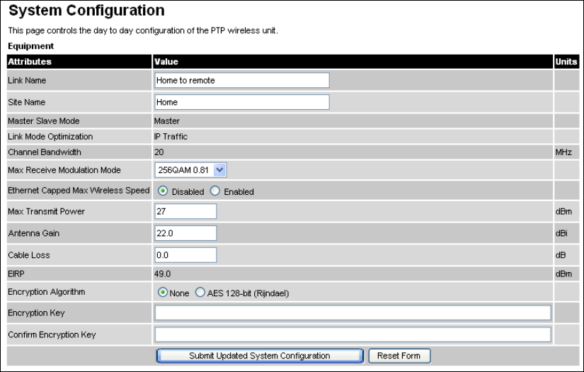
Configuring the PTP 600 Chapter 6 Operation
phn-0896_009v003
6-20 UNDER DEVELOPMENT Feb 2010
Figure 6-8 System Configuration Page
While the majority of the system configuration is entered during installation and
should never require changing, this page offers the system administrator the ability to
change the basic system parameters for both the wireless and Ethernet components.
The System Configuration page contains the following attributes:
Link Name
User defined identity for the unit (max 63 characters).
Site Name
User defined name for the site, with additional notes (if required).
Master Slave Mode
Current settings is displayed This can be modified using the Installation pages, as
described in Installation pages on page 6-51.
Link Mode Optimization
Current settings is displayed This can be modified using the Installation pages, as
described in Installation pages on page 6-51.

User Guide: PTP 600 Series Configuring the PTP 600
phn-0896_009v003
Feb 2010 UNDER DEVELOPMENT 6-21
Channel Bandwidth
Current settings is displayed This can be modified using the Installation pages, as
described in Installation pages on page 6-51.
Max Receive Modulation Mode
This is the maximum mode the unit will use as its adaptive modulation. By default the
Max Receive Modulation Mode is the highest mode available.
For minimum error rates, set the maximum modulation mode to the minimum
necessary to carry the required traffic.
Ethernet Capped Max Wireless Speed
When enabled, this option will cap the wireless speed to a mode that the connected
Ethernet connection can sustain.
Maximum Transmit Power
This specifies the maximum transmit power in dBm of the system. It is country
dependent and although the user can change this in 1dB steps, it will be limited to that
country’s regulations.
NOTE
UK requirement: In the UK there is a legal requirement to provide a
minimum of 19 dB of transmit power control range. When the equipment is
operating with a UK License Key, an additional facility is provided on the
configuration page that allows the transmitted power to be reduced by 19 dB
compared to the maximum allowed with a simple single step control..
Why Reduce Transmit Power? If the link losses are low and the link data
rate and availability targets are being easily achieved, the transmitted power
level may be reduced with a consequent benefit to other users of the band,
such as fixed satellite links.
Antenna Gain, Cable Loss and EIRP
Only displayed when Platform Variant is set to “Connectorized” in the Installation
pages. For more information about the configuration of connectorized PTP 600 units,
refer to Software and features on page 8-3.
Encryption Algorithm, Encryption Key and Confirm Encryption Key
Only displayed when AES encryption is enabled by license key. For more information,
refer to Enabling AES encryption at the wireless interface on page 6-96.
Configuring the PTP 600 Chapter 6 Operation
phn-0896_009v003
6-22 UNDER DEVELOPMENT Feb 2010
Spectrum management
Spectrum Management Selection is the PTP 600 Series feature that monitors the
available wireless spectrum and directs both ends of the wireless link to operate on a
channel with a minimum level of co-channel and adjacent channel interference.
Wireless channels
The PTP 600 Series operates using a set of predefined overlapping channels. There are
a different number of channels, depending on the raster mode selected. Each channel
occupies 30 MHz, 20 MHz, 15 MHz, 10 MHz or 5 MHz of wireless spectrum and is
offset in center frequency from its neighboring channel by 10 MHz or 6 MHz. It is
important to note that adjacent channels on the Spectrum management display have a
10 MHz or 6 MHz overlap to the adjacent channel.
The default channelization can be modified by varying the lower center frequency
attribute in the installation wizard, as described in Installation step 2 - wireless
configuration on page 6-59.
Spectrum management measurements
The PTP 600 Series performs two mean signal measurements per TDD cycle, per
channel. This mean measurement represents the mean received signal power for the
40 microseconds measurement period.
The Spectrum Management algorithm collects measurements equally from all
channels. This process is called the Channel Availability Check (hereafter referred to
by the acronym CAC). The CAC uses a round-robin channel selection process to collect
an equal amount of measurements from each channel. It is important to note that the
CAC measurement process is not altered by the channel barring process.
Measurements are still collected for all channels irrespective of the number of barred
channels.
Measurement analysis
Spectrum Management uses statistical analysis to process the received peak and mean
measurement. The statistical analysis is based on a fixed, one minute, measurement
quantization period. Spectrum Management collects data for the specified
quantization period and only at the end of the period is the statistical analysis
performed.

User Guide: PTP 600 Series Configuring the PTP 600
phn-0896_009v003
Feb 2010 UNDER DEVELOPMENT 6-23
The analysis produces three key metrics for each channel:
Peak of Means
This is the largest mean interference measurement encountered during the
quantization period. The peak of means is similar to the peak of peaks and is useful for
detecting slightly longer duration spikes in the interference environment.
99.9% Percentile of the Means
This is the value of mean interference measurement which 99.9% of all mean
measurements fall below, during the quantization period. The 99.9% percentile metric
is useful for detecting short duration repetitive interference that by its very nature has
a minimal effect of the mean of means.
Mean of Means
This is the arithmetic mean of the measured means during a quantization period. The
mean of means is a coarse measure of signal interference and gives an indication of
the average interference level measured during the quantization period. The metric is
not very good at predicting intermittent interference and is included to show the
spread between the mean of means, the 99.9% percentile and the peak of means.
NOTE
The arithmetic mean is the true power mean and not the mean of the values
expressed in dBm.
Spectrum Management uses the 99.9% percentile as the prime interference
measurement. All subsequent references to interference level refer to this
percentile measurement.
Statistical summary
The display of statistical measurement on the spectrum management page always
shows a statistical summary of all channel measurement. The statistical summary is
controlled by the Statistics Window attribute. This attribute defaults to a value of
twenty minutes, which means that the mean and percentile values displayed for each
channel are calculated over the 20 minute period. All channel decisions are made
using the values computed over the statistics window period.

Configuring the PTP 600 Chapter 6 Operation
phn-0896_009v003
6-24 UNDER DEVELOPMENT Feb 2010
The spectrum management master / slave relationship
The Spectrum Management operates in a master / slave relationship. The master is
assumed to be the link master configured during installation. All Spectrum
Management configuration changes MUST be performed from the master. To enforce
this, the Spectrum Management web page has a different appearance depending if you
are viewing the data from the master or slave.
All configuration changes are applied at the master only. These changes are then
messaged from the master to the slave. Any Spectrum Management configuration
messages received at the slave are stored in non-volatile memory. This enables both
master and slave to keep identical copies of Spectrum Management configuration data
in their non-volatile memories. It is therefore possible to swap master and slave roles
on an active Point-to-Point link without modifying Spectrum Management
configuration.
Figure 6-9 shows an example Spectrum Management webpage as seen from the
master.
Figure 6-10 shows an example Spectrum Management webpage as seen from the
slave. It should be noted that the key configuration attributes are not available on the
slave web page.
NOTE
These examples are for 15 MHz operation; other channel bandwidths are
similar. The width of the vertical green bar represents the channel width.
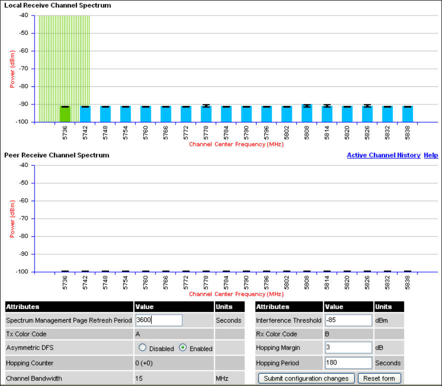
User Guide: PTP 600 Series Configuring the PTP 600
phn-0896_009v003
Feb 2010 UNDER DEVELOPMENT 6-25
Figure 6-9 Spectrum Management as seen from the Master
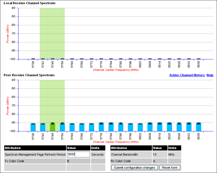
Configuring the PTP 600 Chapter 6 Operation
phn-0896_009v003
6-26 UNDER DEVELOPMENT Feb 2010
Figure 6-10 Spectrum Management as seen from the Slave
User Guide: PTP 600 Series Configuring the PTP 600
phn-0896_009v003
Feb 2010 UNDER DEVELOPMENT 6-27
Spectrum management configuration
The following section describes the user modifiable configuration accessible from the
Spectrum Management webpage (Figure 6-9). It is recommended that the default
values are maintained. If the user believes that the performance of the Spectrum
Management algorithm requires some modifications this should only be done after
consulting the Motorola Point-to-Point distributor or one of the system field support
engineers.
The Spectrum Management page contains the following fields:
Page Refresh Period
The page refreshes automatically according to the setting entered here (in seconds).
Hopping Margin
Spectrum Management uses this margin when making a channel hop decision. If the
interference level of the target channel is lower than that of the active channel by at
least the Hopping Margin, the link will hop to the target channel. The default setting is
3 dB in non-radar regions, or 10 dB in radar regions.
Asymmetric DFS
Only displayed in non-radar regions when i-DFS is enabled. The default configuration
of symmetric operation constrains the link to operate symmetrically, using the same
transmit and receive channels. When in symmetric mode the slave unit will always
follow the master. If the master moves to a new channel the slave will hop to the same
channel. When the Point-to-Point link is configured as an asymmetric link both the
master and slave are free to select the best channel from their own set of local
interference metrics.
Spectrum Management Control
Only displayed in radar regions. The options are “DFS” and “DFS with i-DFS”
Hopping Period (not configurable)
The Spectrum Management algorithm evaluates the metrics every ‘Hopping Period’
seconds (180 seconds by default) looking for a channel with lower levels of
interference. If a better channel is located, Spectrum Management performs an
automated channel hop. If SNMP or SMTP alerts are enabled an SNMP TRAP or an
email alert is sent warning the system administrator of the channel change.
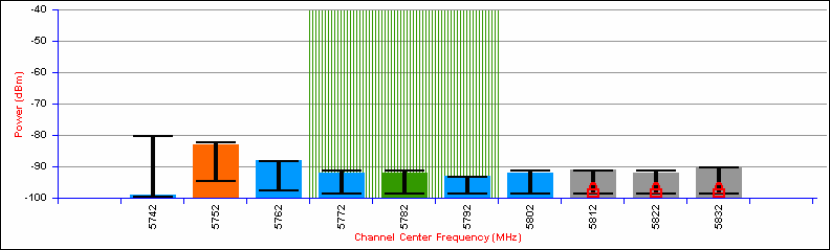
Configuring the PTP 600 Chapter 6 Operation
phn-0896_009v003
6-28 UNDER DEVELOPMENT Feb 2010
Hopping Counter
This is used to record the number of channel hops. The number in the “(+)” brackets
indicates the number of channel changes since the last screen refresh.
Interference Threshold
Spectrum Management uses the interference threshold to perform instantaneous
channel hops. If the measured interference on a channel exceeds the specified
threshold, then i-DFS will instruct the wireless to immediately move to a better
channel. If a better channel cannot be found the PTP 600 Series will continue to use
the current active channel. (Default –85 dBm).
Channel Bandwidth (not configurable)
This shows the value of the variable channel bandwidth selected.
Barring channels
Channels can only be barred / unbarred by the system administrator from the master
Spectrum Management web page. The barring / unbarring operations are disabled on
the slave web page. If an attempt to bar / unbar a channel is made at the slave, a
warning dialog is generated.
Barring/Unbarring of channels is performed by clicking the appropriate channel on the
local or peer channel spectrum plots on the master web page. Each bar / unbar
attempt will be proceeded by a confirmation dialog. It should be noted that the
channel bar will take effect immediately and is not related to the measurement
quantization period.
Master and slave channel spectrum graphics
Spectrum Management presents its computed statistical measurements in a graphical
display on both the master and slave Spectrum Management web page.
Figure 6-11 Example spectrum management graphic

User Guide: PTP 600 Series Configuring the PTP 600
phn-0896_009v003
Feb 2010 UNDER DEVELOPMENT 6-29
The X-axis shows a stylized view of the 9 or 10 selectable wireless channels. It is
important to note that adjacent channels on the display have a 10 MHz overlap. The
display separates the display of channels to help the clarity of the resultant display.
The axis is labeled using the channel center frequencies in MHz.
The Y-axis shows the interference power levels from –100 to –40 dBm.
The active channel (channel 5 in Figure 6-11) is always marked using hatched green
and white lines. The width of the hatching is directly proportional the channel
bandwidth spectral occupancy of the channel.
The individual channel metrics are displayed using a colored bar and an ‘I’ bar.
The colored bar represents the following channel state:
Table 6-1 Spectrum management change state key
Green Active The channel is currently in use, hosting the
Point-to-Point wireless link
Orange Interference
The channel has interference above the
interference threshold
Blue Available
The channel has an interference level below
the interference threshold and is considered by
the Spectrum Management algorithm suitable
for hosting the Point-to-Point link
Grey Barred
The system administrator has barred this
channel from use. For improved visibility, an
additional red ‘lock’ symbol is used to indicate
that a channel is barred.
The top of the colored bar represents the 99.9% percentile metric for specific channel.
The ‘I’ Bar is used to display the mean of means and peak of means metrics. The lower
horizontal bar represents the mean of means and the upper horizontal bar represents
the peak of means. The vertical bar is used as a visual cue to highlight the statistical
spread between the peak and the mean of the statistical distribution.
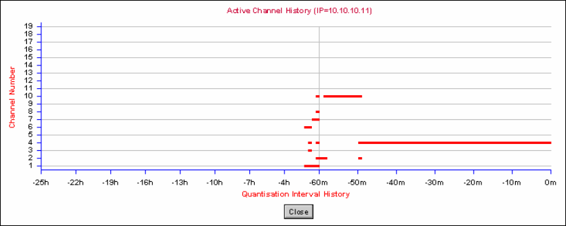
Configuring the PTP 600 Chapter 6 Operation
phn-0896_009v003
6-30 UNDER DEVELOPMENT Feb 2010
Active channel history
The active channel history is a time series display of the channels used by the PTP 600
Series over the last 25 hours. The active channel history is activated from the main
Spectrum Management page using the ‘Active Channel History’ hyperlink. An example
of the active channel history display is shown in Figure 6-12. Where there are parallel
entries on the display this signifies that the wireless link occupied this channel during
the measurement period. The measurement periods are one minute (from zero to sixty
minutes) and twenty minutes from (60 minutes to twenty five hours).
Figure 6-12 Active channel history screen
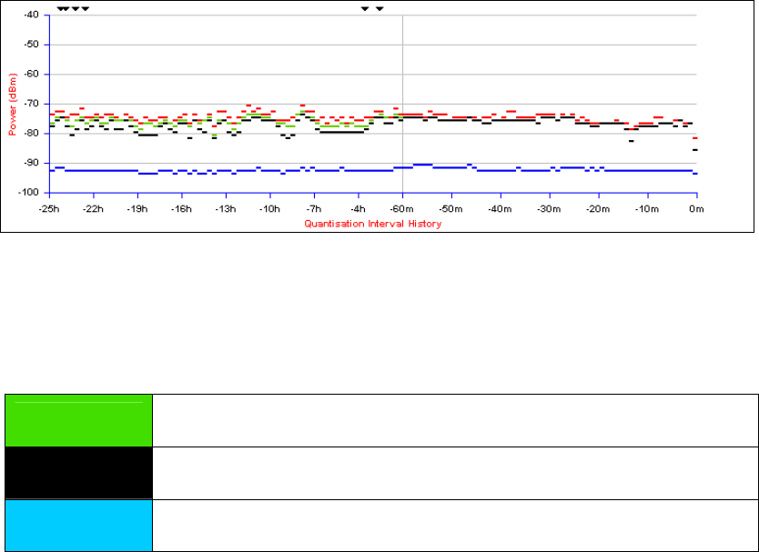
User Guide: PTP 600 Series Configuring the PTP 600
phn-0896_009v003
Feb 2010 UNDER DEVELOPMENT 6-31
Viewing historic spectrum management metrics
Spectrum Management allows the system administrator to view the results of previous
measurement quantization periods. Holding down the shift key and clicking the
appropriate channel on the local channel spectrum plots activates this feature. This
feature is available on both the master and slave web page.
Figure 6-13 Spectrum management time series plot
Figure 6-13 shows an example time series plot. A time series plot displays the previous
132 measurement quantization periods. If the PTP 600 Series has not been running for
132 quantization periods then only the number of measurement quantization periods
that are available are displayed.
Table 6-2 Spectrum management time series key
GREEN Peak of Means interference measurement
BLACK 99.9% percentile of means interference measurement
BLUE Mean of Means interference measurement
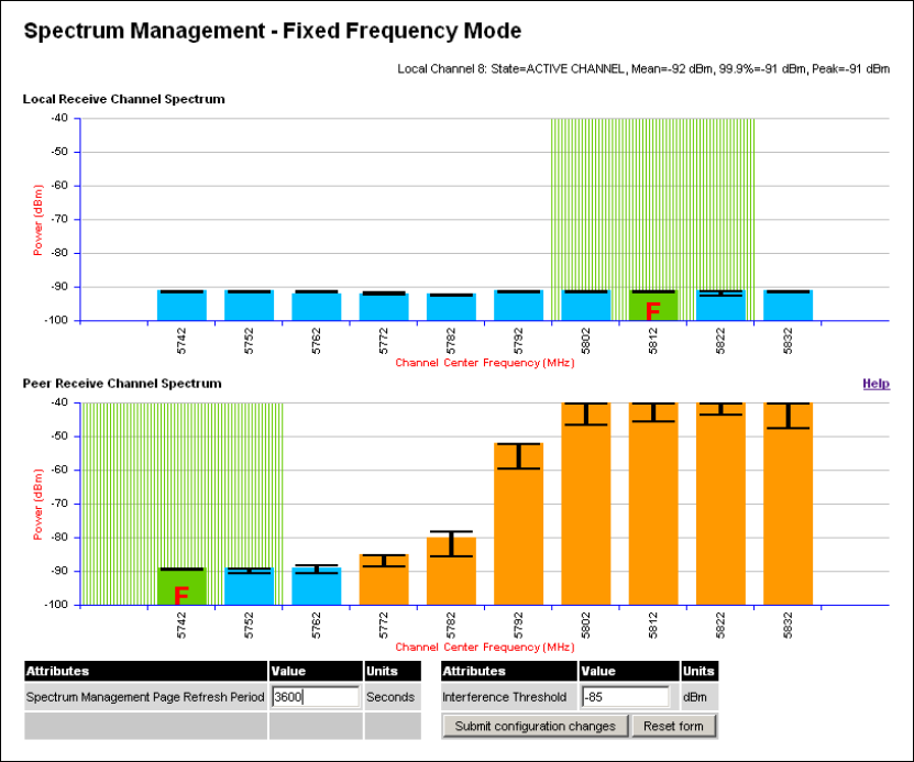
Configuring the PTP 600 Chapter 6 Operation
phn-0896_009v003
6-32 UNDER DEVELOPMENT Feb 2010
Spectrum management (fixed frequency)
The PTP 600 Series software allows a user to optionally fix transmit and receive
frequencies for a wireless link. Once configured, the spectrum management software
will not attempt to move the wireless link to a channel with lower co and adjacent
channel interference. Therefore this mode of operation is only recommended for
deployments where the installer has a good understanding the prevailing interference
environment. (See Installation step 2 - wireless configuration on page 6-59). Care must
also be taken to ensure that the frequency allocations at each end of the link are
compatible. To help the user when identifying the mode of operation Spectrum
Management uses two visual cues. See Figure 6-14. The main page title identifies the
mode of operation using the “Fixed Frequency Mode” postfix and the selected
channels are identified by a red capital ‘F’.
Figure 6-14 Spectrum Management Fixed Frequency Mode page
Channel barring is disabled in fixed frequency mode; it is not required as dynamic
channel hopping is prohibited in this mode.
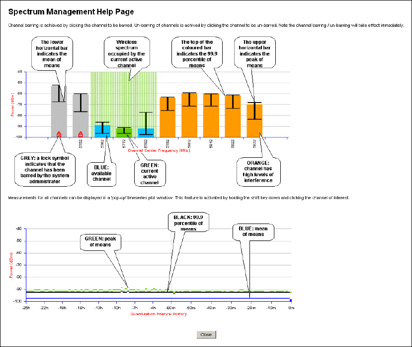
User Guide: PTP 600 Series Configuring the PTP 600
phn-0896_009v003
Feb 2010 UNDER DEVELOPMENT 6-33
The only controls available to the master are the Statistics Window and Interference
Threshold attributes. They will have no effect on the operation of the wireless link and
will only effect the generation of the channel spectrum graphics.
The active channel history menu is removed in this mode of operation as channel
hopping is prohibited.
Figure 6-15 Spectrum Management Help Page (fixed frequency)
Configuring the PTP 600 Chapter 6 Operation
phn-0896_009v003
6-34 UNDER DEVELOPMENT Feb 2010
Spectrum management control with radar avoidance
When operating with Radar Avoidance enabled the following variances in operation
apply:
• The words “Radar Avoidance” are appended to the “Spectrum Management” title
at the top of the screen. See Figure 6-16 and Figure 6-17.
• The only controls available to the master are the Interference Threshold
attribute. This has no effect on the operation of the wireless link and will only
affect the generation of the channel spectrum graphics. See Figure 6-16.
• Extra color coding of the interference histogram is provided. See Table 6-3.
When operating with RTTT (Road transport and Traffic Telematics) Avoidance enabled
or other regulatory restrictions on channel usage the following variances apply:
• All channels marked with a ‘no entry’ symbol with their associated statistics
colored black are the prohibited channels. See Figure 6-16 and Figure 6-17.
These channels are never used to host the wireless link, but CAC measurements
are still taken so that adjacent channel biases can be calculated correctly and so
the user can see if other equipment is in use.
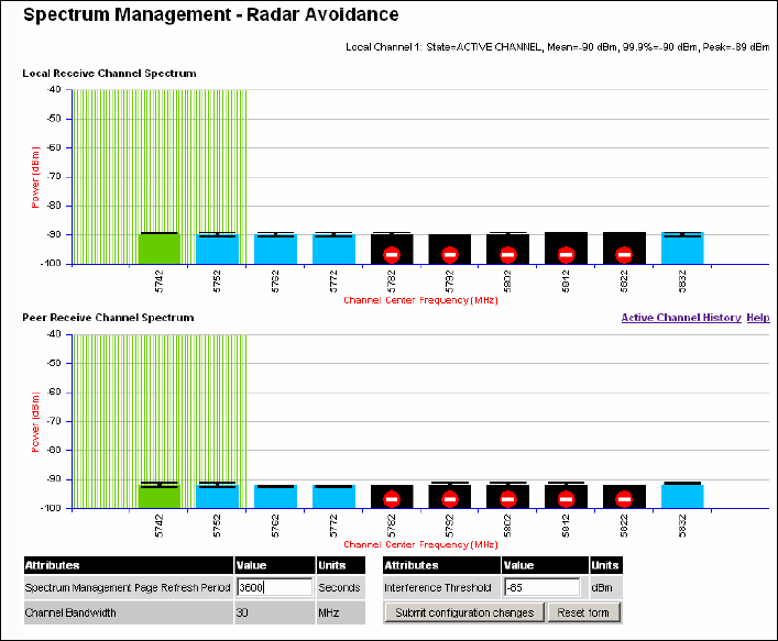
User Guide: PTP 600 Series Configuring the PTP 600
phn-0896_009v003
Feb 2010 UNDER DEVELOPMENT 6-35
Figure 6-16 Spectrum Management Radar Avoidance page - Master
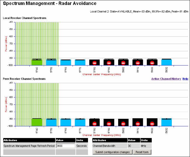
Configuring the PTP 600 Chapter 6 Operation
phn-0896_009v003
6-36 UNDER DEVELOPMENT Feb 2010
Figure 6-17 Spectrum Management Radar Avoidance page - Slave

User Guide: PTP 600 Series Configuring the PTP 600
phn-0896_009v003
Feb 2010 UNDER DEVELOPMENT 6-37
The colored bar represents the following channel state:
Table 6-3 Spectrum management change state key with operational restrictions
Green Active The channel is currently in use hosting the Point-to-Point
wireless link
Orange Interference
The channel has interference above the interference
threshold
Blue Available
The channel has an interference level below the
interference threshold and is considered by the Spectrum
Management algorithm suitable for hosting the
Point-to-Point link
Grey Barred
The system administrator has barred this channel from
use. Because the low signal levels encountered when a unit
is powered up in a laboratory environment prior to
installation (which makes the grey of the channel bar
difficult to see). An additional red ‘lock’ symbol is used to
indicate that a channel is barred.
Red Radar
Detected
Impulsive Radar Interference has been detected on this
channel and the channel is unavailable for 30 minutes. At
the end of the 30 minute period a Channel Availability
Check is required to demonstrate no radar signals remain
on this channel before it can be used for the radio link.
Region
Bar Region Bar This channel has been barred from use by the local region
regulator
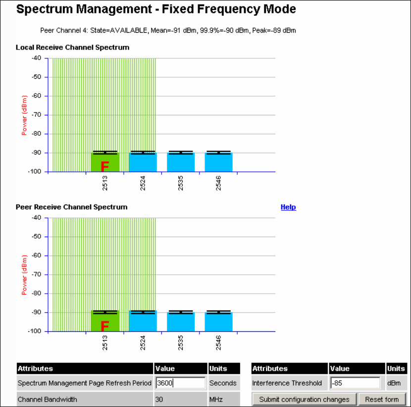
Configuring the PTP 600 Chapter 6 Operation
phn-0896_009v003
6-38 UNDER DEVELOPMENT Feb 2010
PTP 25600 spectrum management example
As described in Section PTP 25600 available spectrum settings on page 4-21, the PTP
25600 frequency variant can operate in three frequency bands. Figure 6-18 shows an
example of a Lower Band with a 30 MHz channel bandwidth.
Figure 6-18 PTP 25600 example of Spectrum Management page
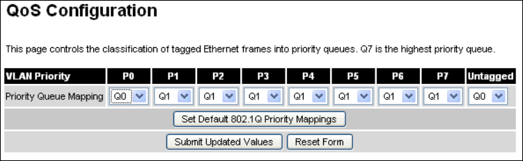
User Guide: PTP 600 Series Configuring the PTP 600
phn-0896_009v003
Feb 2010 UNDER DEVELOPMENT 6-39
QoS configuration
The QoS configuration page (Figure 6-19) allows the system administrator to configure
the classification of priority encoded Ethernet frames into up to eight traffic classes.
Figure 6-19 QoS Configuration page
The QoS Configuration page contains the following attributes:
Priority Queue Mapping
Specifies the VLAN priority flag to packet queue mapping. The higher the queue
number the greater its priority.

Configuring the PTP 600 Chapter 6 Operation
phn-0896_009v003
6-40 UNDER DEVELOPMENT Feb 2010
Quality of Service Default Settings
The default classification rules are as shown in Table 6-4.
Table 6-4 QoS default settings
Link Layer Priority Traffic Class
0 Q0
1 Q1
2 Q1
3 Q1
4 Q1
5 Q1
6 Q1
7 Q1
Untagged Q0
In the case where the ODU is upgraded from an earlier release that supports only two
traffic classes, the classification rules will be determined by the stored value of "VLAN
High Priority Traffic Threshold". For example, if the existing threshold was set to
"VLAN User Priority 4 and Above" then the classification rules would be initialized as
shown in Table 6-5.
Table 6-5 Classification rules upgrade example
Link Layer Priority Traffic Class
0 Q0
1 Q0
2 Q0
3 Q0
4 Q1
5 Q1
6 Q1

User Guide: PTP 600 Series Configuring the PTP 600
phn-0896_009v003
Feb 2010 UNDER DEVELOPMENT 6-41
Link Layer Priority Traffic Class
7 Q1
Untagged Q0
The user interface also allows configuration of IEEE802.1Q classification rules as
shown in Table 6-6 using the button ‘Set Default 802.1Q Priority Mappings’.
Table 6-6 IEEE802.1Q classification rules
Link Layer Priority Traffic Class
0 Q1
1 Q0
2 Q2
3 Q3
4 Q4
5 Q5
6 Q6
7 Q7
Untagged Q1
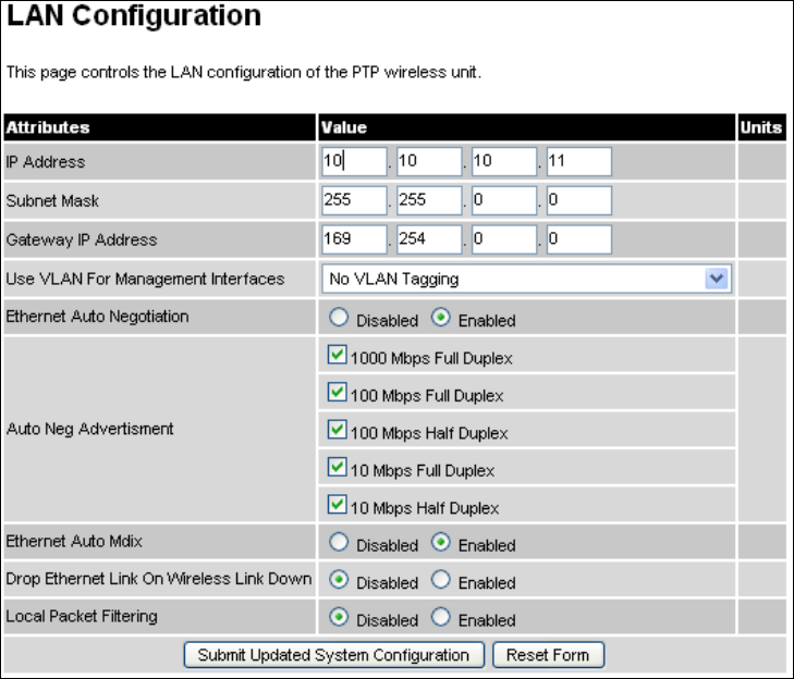
Configuring the PTP 600 Chapter 6 Operation
phn-0896_009v003
6-42 UNDER DEVELOPMENT Feb 2010
Configuring the IP and Ethernet interfaces
LAN configuration
The LAN configuration page (Figure 6-20) is used by the system administrator to
configure the PTP 600 Series LAN interface.
Figure 6-20 LAN Configuration page
All of the LAN Configuration attributes are non-volatile, so once set, they will be used
by the unit even after a power on reboot. The LAN Configuration page contains the
following fields:
IP Address
Internet protocol (IP) address. This address is used by the family of Internet protocols
to uniquely identify this unit on a network.

User Guide: PTP 600 Series Configuring the PTP 600
phn-0896_009v003
Feb 2010 UNDER DEVELOPMENT 6-43
Subnet Mask
A subnet allows the flow of network traffic between hosts to be segregated based on a
network configuration.
Gateway IP Address
The IP address of a computer / router on the current network that acts as a gateway.
Use VLAN For Management Interfaces
This controls use of VLAN tags at the management interfaces
(WWW/SNMP/SMTP/SNTP). See LAN configuration page for VLAN on page 6-45.
Ethernet Auto Negotiation
This enables the Ethernet configuration to be forced rather than auto negotiated.
CAUTION
The IEEE802.3 specification recommends enabling Auto Negotiation. The
configuration should only be forced if you are having problems with auto
negotiation. You must ensure that you configure both this unit and the
Ethernet port to which it is connected identically. If you force a fixed
Ethernet Configuration on the PTP 600 Series then you MUST also force the
same fixed configuration on the equipment to which it is connected. If you
fail to force the configuration of the connected equipment, its automatic
configuration mechanisms will normally cause a duplex mismatch, and you
will receive greatly reduced throughput!
When Ethernet Auto Negotiation is Disabled, the format of the LAN configuration page
changes see LAN Configuration Page – Manual Ethernet Configuration on page 6-48.
Auto Neg Advertisement
This controls the rates that the auto negotiation mechanism will advertise as available.
CAUTION
Over the air throughput will be capped to the rate of the Ethernet interface
at the receiving end of the link.
Ethernet Auto Mdix
This enables/disables the Auto Medium Dependent Interface (MDI)/Medium Dependent
Interface Crossover (MDIX) capability. Default is “Enabled”.
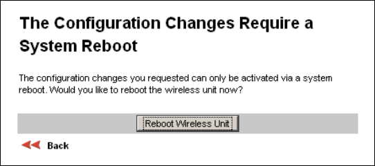
Configuring the PTP 600 Chapter 6 Operation
phn-0896_009v003
6-44 UNDER DEVELOPMENT Feb 2010
Drop Ethernet Link On Wireless Link Down
When this option is enabled the Ethernet link is momentarily dropped when the
wireless link goes down. This feature is used to indicate to the connected network
equipment that this Ethernet link is no longer available, thus causing STP (Spanning
Tree Protocol) to re-route packets through an alternative link.
Local Packet Filtering
When Local Packet Filtering is “Enabled”, the bridge learns the source MAC addresses
of devices transmitting Ethernet packets on the local Ethernet network, and only
bridges packets to the remote unit if the destination MAC address has not been
learned as a 'local' device.
When Local Packet Filtering is ‘Disabled’ the bridge does not learn the source MAC
addresses of devices transmitting Ethernet packets on the local Ethernet network, and
bridges ALL Ethernet packets received to the remote unit. Local Packet Filtering
should be disabled when external Ethernet switching hardware or a router is present.
The default setting for Local Packet Filtering is disabled.
Reboot verification
A number of attributes, such as IP Address, Subnet Mask and Gateway IP Address and
VLAN settings will require a reboot before they are used. If any of these attributes are
changed a reboot screen appears asking the user to verify the reboot (Figure 6-21 or
Figure 6-22).
Figure 6-21 Configuration Reboot page
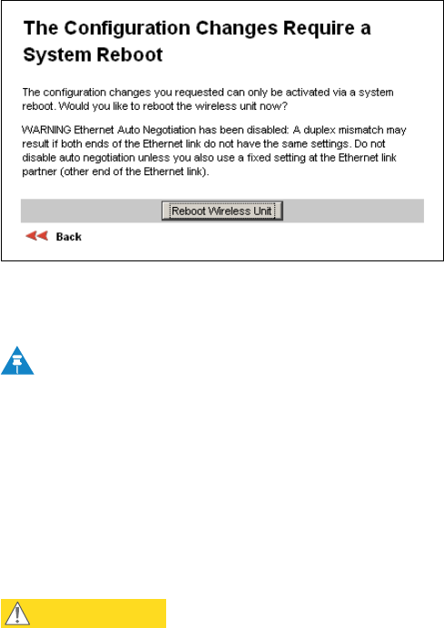
User Guide: PTP 600 Series Configuring the PTP 600
phn-0896_009v003
Feb 2010 UNDER DEVELOPMENT 6-45
Figure 6-22 Configuration Reboot page - Ethernet auto negotiation disabled
This will be followed by a pop-up dialogue box asking to confirm the action.
NOTE
At this point you will lose connection to the unit. If you have just changed the
IP Address, you now have to reconnect to the unit using the address just set.
LAN configuration page for VLAN
The layout of the LAN Configuration page changes if this attribute is enabled in order
to allow the VLAN VID and VLAN Priority to be set, see Figure 6-23. The VLAN
settings are applied only after the unit is rebooted.
CAUTION
You must ensure that you can access the VLAN which you configure here,
otherwise you will be unable to access the unit following the next reboot.
The PTP 600 management function is only compatible with single VLAN
tagged packets. Any management packet with two or more packets will be
ignored.
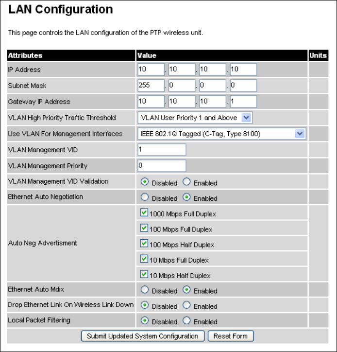
Configuring the PTP 600 Chapter 6 Operation
phn-0896_009v003
6-46 UNDER DEVELOPMENT Feb 2010
Figure 6-23 LAN Configuration page with VLAN fields
When VLAN is enabled, the LAN Configuration page contains the following extra
fields:
Use VLAN For Management Interfaces
This control can be configured with one of the following three values:
o No VLAN Tagging
o IEEE 802.1Q Tagged (C-Tag, Type 8100)
o IEEE 802.1ad Tagged (S-Tag or B-Tag, Type 88a8)
User Guide: PTP 600 Series Configuring the PTP 600
phn-0896_009v003
Feb 2010 UNDER DEVELOPMENT 6-47
VLAN Management VID
This 802.1Q or 802.1ad VLAN ID (VID) will be included in packets generated by the
management interfaces. Valid settings are in the range 0 to 4094.
VLAN Management Priority
This 802.1Q or 802.1ad VLAN Priority will be included in packets generated by the
management interfaces. Valid settings are in the range 0 to 7.
VLAN Management VID Validation
If enabled, the management interfaces will only respond to Ethernet packets tagged
with the configured Management VID; otherwise packets with any VID will be
accepted.
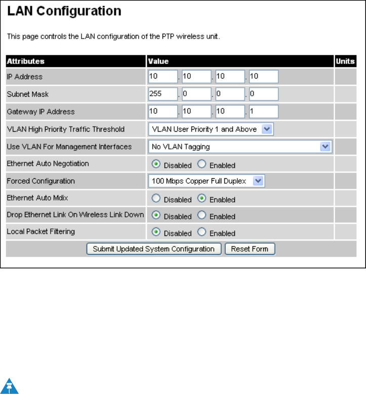
Configuring the PTP 600 Chapter 6 Operation
phn-0896_009v003
6-48 UNDER DEVELOPMENT Feb 2010
LAN configuration page for manual ethernet configuration
The layout of the LAN Configuration page changes if Ethernet Auto Negotiation is
Disabled, see Figure 6-24.
Figure 6-24 LAN Configuration page for manual Ethernet configuration
When Ethernet Auto Negotiation is Disabled, the LAN Configuration page contains the
following extra field:
Force Configuration
This option allows the user to force the speed and duplex setting of the Ethernet
interface. Over the air throughput will be capped to the rate of the Ethernet interface
at the receiving end of the link.
NOTE
Instead of forcing configuration, the IEEE802.3 specification recommends
enabling Auto Negotiation with only the specific ability or abilities
advertised.
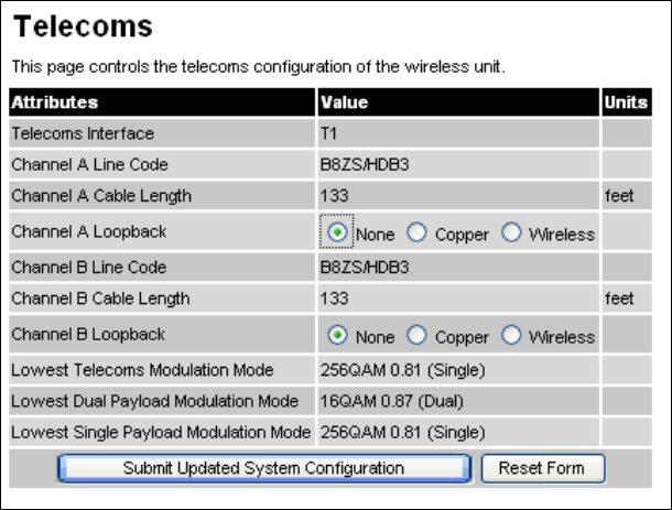
User Guide: PTP 600 Series Configuring the PTP 600
phn-0896_009v003
Feb 2010 UNDER DEVELOPMENT 6-49
Configuring the telecoms circuits
The Telecoms page (Figure 6-25) is available when the Telecoms Interface has been
set to either T1 or E1 in the Installation Wizard.
The unit displays the interface setting and line code for the available telecoms
channels. The PTP 600 Series is able to support two T1 or E1 channels. These channels
are referred to as "Channel A" and "Channel B".
The "Channel B" configuration and controls will be displayed only when the second
channel is enabled.
Figure 6-25 Telecoms page
The Telecoms page contains the following fields:
Telecoms Interface
May be either T1 or E1, reflecting the Installation Wizard setting.
Line Code
Displays the Line Code setting for each channel. The Line Code configuration must
match the configuration of the connected equipment and may be set using the
Installation Wizard.
Configuring the PTP 600 Chapter 6 Operation
phn-0896_009v003
6-50 UNDER DEVELOPMENT Feb 2010
Cable Length
The Cable Length setting is applicable in T1 mode only and shows the cable length
specified in the installation wizard.
Loopback
Allows the T1 or E1 data stream to be looped back at the copper or wireless interface.
During normal operation the loopback must be set to "None". It may be helpful during
installation to test the telecoms links by performing loopback connections.
A "Copper" loopback connects the received data on a given telecoms interface to the
transmit interface. A "Copper" loopback may be used, in conjunction with a Bit Error
Rate Tester, to confirm that the correct connections have been made to the ODU. This
mode cannot be used for resistance tests as it is only capable of looping back valid
telecoms signals.
A "Wireless" loopback sends the telecoms data received across the wireless link back
across the link on the same Telecom channel. The link may be checked using, for
example, a Bit Error Rate Tester to ensure that no errors are detected.
A typical T1 or E1 installation might include a "Copper" loopback on the local unit
followed by a "Wireless" loopback on the remote unit.
It is important to remove all loopbacks on channels for normal operation. Alarms on
the Home Page indicate the presence of loopbacks on either channel.
Lowest Telecoms Modulation Mode
The user defined lowest modulation mode at which telecoms data can be sent. If the
link cannot sustain telecoms data in this mode then the effective lowest modulation
mode may differ
Lowest Dual Payload Modulation Mode; Lowest Single Payload Modulation
Mode
Indicate the effective lowest modulation mode at which telecoms data can be sent,
subject to wireless capacity and latency limitations. Under some circumstances, these
settings may differ from the user defined Lowest Telecoms Modulation Mode
described above.

User Guide: PTP 600 Series Installation pages
phn-0896_009v003
Feb 2010 UNDER DEVELOPMENT 6-51
Installation pages
There follows a description of the installation pages along with their use during the
installation configuration process. The actual installation process is described in
Manual configuration on page 6-52.
NOTE
This section assumes that the integrated PTP 600 is being installed. If the
connectorized variant is being installed, refer to Software and features on
page 8-3 for details of the additional functionality that must be configured.
Factory configuration
All wireless links are shipped as paired units. They are pre-configured at the factory so
that they can be installed without the user supplying any configuration. Each wireless
link is shipped with the
PTP 600 Installation Guide
. Attached to this guide is a
summary of the pre-configured configuration data. Table 6-7 shows a sample link
configuration. The values in red type have been committed to the wireless unit’s non-
volatile storage.
Table 6-7 Factory configuration values
Example PTP 600 Series Configuration Data
For your convenience these two units have been pre-configured
as a link
Units:
ODU serial number ODU serial number
016780000FFF 016780000FC7
Ethernet MAC address Ethernet MAC address
00:04:56:80:0F:FF 00:04:56:80:0F:C7
Configured as:
Master Slave
Target MAC address Target MAC address
00:04:56:80:0F:C7 00:04:56:80:0F:FF

Installation pages Chapter 6 Operation
phn-0896_009v003
6-52 UNDER DEVELOPMENT Feb 2010
License Key License Key
A471-FE88-428D-E1F3 534F-4F54-D1B0-E2DA
IP Address IP Address
169.254.1.2 169.254.1.1
CAUTION
The factory default configuration is limited in range to 40 Km (25 miles). If
you wish to install a wireless link with a range of > 40 Km (> 25 miles) and
< 200 Km (< 124 miles) or < 5 Km (< 3 miles) you must follow Manual
configuration on page 6-52.
The factory default configuration is set to Region 1. Region 1 allows the PTP
600 Series a maximum transmit power of 25 dBm. If the local regulatory
regime limits the maximum transmit power (EIRP) to less than 25 dBm, you
should obtain a new license key containing the correct region code from
your local distributor or direct from Motorola. Alternatively in the short
term, you should reduce the maximum transmit power by following the
procedures in Manual configuration on page 6-52.
Manual configuration
If the installer / system administrator wishes, they may modify the default installation
configuration. If only the IP addresses (network configuration) are incorrect it is
recommended that the values are changed via the configuration menu, as described in
LAN configuration on page 6-42.
NOTE
If any other parameters (for example region code) require modification, then
it is recommended that the system administrator use the Installation Wizard.
The PTP 600 Series operational software requires a license key (Figure 6-26) to enable
the wireless bridging capability and programs region code specific parameters in to
the unit.
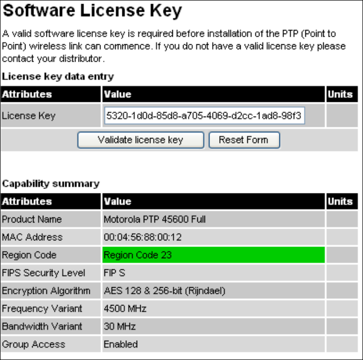
User Guide: PTP 600 Series Installation pages
phn-0896_009v003
Feb 2010 UNDER DEVELOPMENT 6-53
Figure 6-26 Software License Key page
A license key is programmed into each unit during production and can be found
written on the Configuration Data Summary Label which is attached to the Quick
Install Guide. If subsequently the license key has been mislaid, replacement keys can
be applied for online or via your distributor.
If a valid license key is not detected in the unit’s non-volatile memory then the user is
prompted to enter a valid key. It should be noted that 600 Series units are shipped as
link pairs and, as such, valid license keys are entered during the production process.
To enter a license key simply type or paste the license key into the data entry box
(Figure 6-26) and click the ‘validate license key’ button.
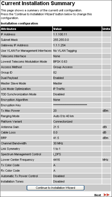
Installation pages Chapter 6 Operation
phn-0896_009v003
6-54 UNDER DEVELOPMENT Feb 2010
Current installation summary
When Installation is selected from the menu navigation bar, the Current Installation
Summary page is displayed (Figure 6-27). Review the current configuration attributes.
If any attributes require changing, select Continue to Installation Wizard.
Figure 6-27 Current installation summary page
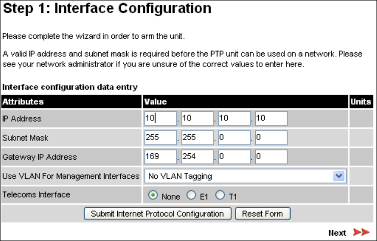
User Guide: PTP 600 Series Installation pages
phn-0896_009v003
Feb 2010 UNDER DEVELOPMENT 6-55
Installation step 1 - interface configuration
Step 1 of the installation process requires the installer to enter the Internet Protocol
(IP) configuration (Figure 6-28).
Figure 6-28 Step 1: Interface Configuration page
The Interface Configuration page contains the following fields:
IP Address
Internet protocol (IP) address. This address is used by the family of Internet protocols
to uniquely identify this unit on a network.
Subnet Mask
A subnet allows the flow of network traffic between hosts to be segregated based on a
network configuration. By organizing hosts into logical groups, a subnet can improve
network security and performance.
Gateway IP Address
The IP address of a computer / router on the current network that acts as a gateway. A
gateway acts as an entrance / exit to packets from / to other networks.
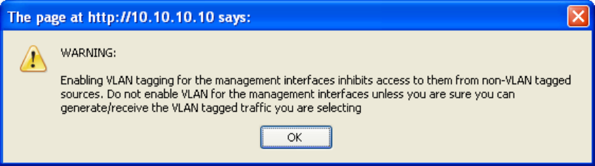
Installation pages Chapter 6 Operation
phn-0896_009v003
6-56 UNDER DEVELOPMENT Feb 2010
Use VLAN Management Interface
Controls whether the management interfaces (HTTP/SNMP/SMTP/SNTP) use a VLAN.
Selecting this option presents the user with extra fields in which to enter the
Management VLAN ID, Priority and whether to validate the VLAN ID. If the user
modifies this control, a warning dialog is displayed see Figure 6-29.
Telecoms Interface
This allows the activation of the PTP 600 Series telecoms interface. The selection
options are None, E1 or T1. Mixed T1/E1 configurations are not permitted.
Figure 6-29 VLAN Warning
Once complete, click the ‘Submit Internet Protocol Configuration’ button or the ‘Next’
link.
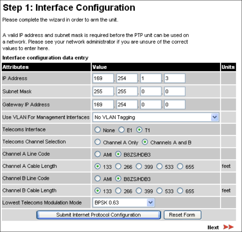
User Guide: PTP 600 Series Installation pages
phn-0896_009v003
Feb 2010 UNDER DEVELOPMENT 6-57
Telecoms interface
If the telecoms interface is configured to either T1 or E1 then Step 1 of the installation
process contains additional configuration fields (Figure 6-30).
Figure 6-30 Step 1: Interface Configuration page for telecoms
The additional E1 or T1 fields are:
Telecoms Channel Selection
This allows the user to configure one or two interfaces (Channel A or Channel A and
B).

Installation pages Chapter 6 Operation
phn-0896_009v003
6-58 UNDER DEVELOPMENT Feb 2010
Channel A Line Code
The line code setting of the telecoms interface. This must match the setting of the
device connected to this interface.
Channel B Line Code
The line code setting of the telecoms interface. This must match the setting of the
device connected to this interface.
NOTE
If a copper loopback is used to test the E1/T1 link, ensure that the test set is
configured manually. If the test set is allowed to configure automatically, neither
it nor the ODU send a signal until they receive one, so the test appears to fail.
Channel A/B Cable Length
This field is applicable to the T1 operating mode only. It configures the T1 transceiver
to output a signal suitable for driving a cable of the specified length. This should be
set to reflect the length of cable between the wireless unit and the connected
equipment.
Lowest Telecoms Modulation Mode
The lowest modulation mode at which telecoms data will be sent, if there is sufficient
link capacity.
In conjunction with the LINKPlanner tool, this setting may be used to optimize the
latency for links which operate in consistently high modulation modes. High data rate
links are able to support lower latencies.
The lowest telecoms modulation mode is selected from a rate ordered drop-down list.
If this selected mode has insufficient capacity to support the telecoms data then the
effective lowest modulation mode, determined when the wireless link starts, will be
higher. The effective lowest modulation mode is displayed on the Telecoms
Configuration page.
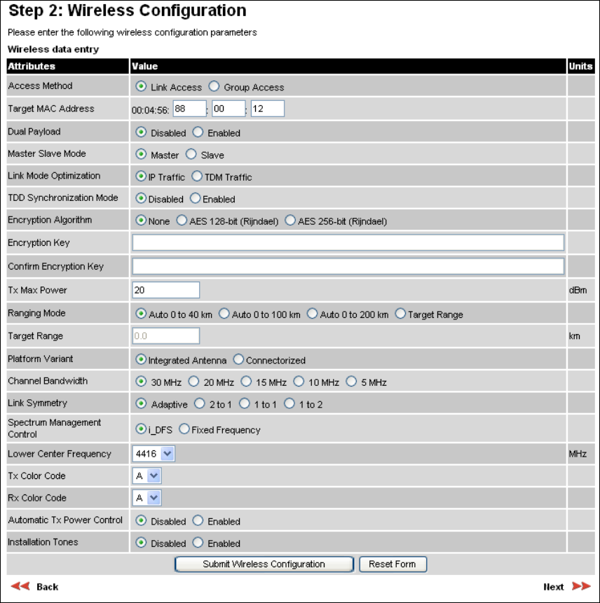
User Guide: PTP 600 Series Installation pages
phn-0896_009v003
Feb 2010 UNDER DEVELOPMENT 6-59
Installation step 2 - wireless configuration
Step 2 of the installation process requires the installer to enter the wireless
configuration parameters. Figure 6-31 is an example of the Wireless Configuration
screen.
Figure 6-31 Step 2: Wireless Configuration page

Installation pages Chapter 6 Operation
phn-0896_009v003
6-60 UNDER DEVELOPMENT Feb 2010
The contents of the Wireless Configuration screen vary depending upon the frequency
variant as follows:
• PTP 25600: Frequency Band field is also displayed.
• Channel Bandwidth options vary depending upon frequency variant and region.
For more information, see Table 1-1.
• PTP 49600: Lower Center Frequency is not displayed.
Screen contents also vary depending upon the options selected as follows:
• If Access Method is set to “Group Access”, the Target MAC Address field is
replaced by Group ID.
• If Spectrum Management Control is set to “Fixed Frequency”, the Lower Center
Frequency field is replaced by Fixed Tx Frequency and Fixed Rx Frequency.
• If Platform Variant is set to “Connectorized”, Antenna Gain and Cable Loss are
also displayed. For more information about the configuration of connectorized
PTP 600 units, refer to Software and features on page 8-3.
The Wireless Configuration page contains the following fields:
Access Method
This controls whether the link can be established between a pre-paired Master and
Slave only (‘Link Access’) or between Master and Slave belonging to the same group
(‘Group Access’).
Target MAC Address
This is only displayed when Access Method is set to ‘Link Access’. This is the MAC
Address of the peer unit that will be at the other end of the wireless link. This is used
by the system to ensure the unit establishes a wireless link to the correct peer. The
MAC Address can be found embedded within the serial number of the unit. The last six
characters of the serial number are the last three bytes of the unit’s MAC address.
NOTE
A PTP 600 Series system is shipped as a pair of units with pre-loaded correct
MAC addresses. Target MAC addresses will only need to be entered if an
existing unit has to be replaced in the field or the units configuration has
been erased.
Group ID
This is only displayed when Access Method is set to ‘Group Access’. It identifies all
units belonging to the same group.
User Guide: PTP 600 Series Installation pages
phn-0896_009v003
Feb 2010 UNDER DEVELOPMENT 6-61
Dual Payload
This controls whether the link takes advantage of the channel condition to increase the
link throughput. If set to ‘Disable’, the robustness of the link is improved. The default
value is ‘Enabled’.
This control is automatically set to ‘Enabled’ if either E1 or T1 is enabled and Lowest
Telecoms Modulation Mode is set to a Dual Payload modulation.
Master Slave Mode
At this point it is necessary to decide which end will designate a Master. The Master
unit is the controlling unit with respect to the point-to-point link and its maintenance.
The master transmits until the link is made, while the Slave listens for its peer and
only transmits when the peer has been identified.
Link Mode Optimization
Optimizes the link behavior according to the type of traffic that will be bridged. There
are two modes to choose from: IP and TDM. For more information, see Link mode
optimization on page 1-20.
TDD Synchronization Mode
Enables the TDD synchronization feature. See Time division duplex synchronization on
page 1-25 for basic description and TDD synchronization configuration on page 6-66
for installation and configuration details.
Encryption Algorithm
This is only displayed when encruption is enabled by license key. The same algorithm
must be used at both ends of the link. For more information, see Enabling AES
encryption at the wireless interface on page 6-96.
Encryption Key
This is only displayed when encryption is enabled by license key. The same key must
be used at both ends of the link. For more information, see Enabling AES encryption at
the wireless interface on page 6-96. When identity based user accounts are enabled,
only the Security Officer can change the encryption key.
Confirm Encryption Key
This is only displayed when encryption is enabled by license key. Must contain the
same value as Encryption Key.
Tx Max Power
This attribute controls the maximum transmit power the unit is permitted to use when
installing and executing the wireless link. The maximum setting for a particular region
or country is controlled by the License Key.

Installation pages Chapter 6 Operation
phn-0896_009v003
6-62 UNDER DEVELOPMENT Feb 2010
Ranging Mode
During installation, the wireless units perform “Automatic Ranging”. The ranging
mode allows the installer to control the behavior of the system’s automatic ranging
algorithms. The default value is 0 to 40 km (0 to 25 miles). If the installer is required
to install a link of greater than 40 km (25 miles) then the ranging mode attribute
MUST be configured to ‘0 to 100km’ (0 to 62 miles) or ‘0 to 200km’ (0 to 124 miles)
mode depending on the range of the link.
NOTE
If preferred, range functions can be configured to operate in miles, as described
in Properties on page 6-131.
Target Range
Installers that know the range between the two wireless units to within ± 1 km can use
the target range mode. The main advantage of the target range mode is that it reduces
the time taken by the units to range. To use the target range mode the installer MUST
select Target Range as the ranging mode and enter the approximate range in km in
the Target range data entry field at both ends of the link.
Platform Variant
Chooses between an integrated unit or a connectorized unit that requires an external
antenna.
Frequency Band
Only displayed for the PTP 25600 frequency variant, which operates in one of three
bands as described in Variable channel bandwidth operation on page 2-5:
o Lower: 2496 MHz to 2568 MHz
o Middle: 2572 MHz to 2614 MHz
o Upper: 2624 MHz to 2690 MHz
Channel Bandwidth
Users can choose a variable channel bandwidth for the available spectrum. The
selection depends upon the frequency variant and region. For more information, see
Table 1-1.

User Guide: PTP 600 Series Installation pages
phn-0896_009v003
Feb 2010 UNDER DEVELOPMENT 6-63
Link Symmetry
(Master only) Values of "Adaptive", "2 to 1", "1 to 1" and "1 to 2" can be selected. The
adaptive setting allows link symmetry to vary dynamically in response to offered traffic
load. The remaining values select three options for fixed division between transmit and
receive time in the TDD frame of the master ODU. The first number in the ratio
represents the time allowed for the transmit direction and the second number
represents the time allowed for the receive direction.
The appropriate matching Link Symmetry is set at the slave ODU automatically. For
example, if Link Symmetry is configured as “2 to 1” at the master ODU, then the slave
ODU will be set automatically as “1 to 2”. In this example, the master-slave direction
has double the capacity of the slave-master direction.
NOTE
Link Symmetry is subject to the following restrictions:
o "Adaptive" is not supported in regions where radar avoidance is in use.
o "Adaptive" is not supported when link optimization is set to "TDM".
o "Adaptive" is not supported in 5 MHz channel bandwidth.
o "2 to 1" and "1 to 2" are not supported in 5 MHz channel bandwidth.
o “2 to 1” and “1 to 2” are not supported when E1/T1 services are enabled.
Spectrum Management Control
Is used to configure the PTP 600 Series Spectrum Management features, see
Spectrum management on page 6-22 for more details. In regions that do not mandate
DFS (Radar Detection), the Spectrum Management Control options are “i-DFS” and
“Fixed Frequency”. In regions that mandate DFS (Radar Detection), the Spectrum
Management Control options are “DFS” and “DFS with i-DFS”.
The Spectrum Management Control is disabled if the regulatory requirement is fixed
frequency only (for example if the frequency variant is PTP 25600).
Lower Center Frequency
Not displayed for the PTP 49600. Not displayed when Spectrum Management Control
is set to “Fixed Frequency”. The software for the PTP 600 Series allows a user to
optionally adjust the channel center frequencies. Changing the Lower Center
Frequency attribute causes all channel center frequencies to be offset. It effectively
slides the channelization up or down.

Installation pages Chapter 6 Operation
phn-0896_009v003
6-64 UNDER DEVELOPMENT Feb 2010
NOTE
Because the 4.9 GHz spectrum is restricted by license, the Lower Center
Frequency is fixed for the PTP 49600 and is therefore not displayed.
CAUTION
The lower center frequency attribute must be configured to the same value for
both the master and slave. Failure to do so will cause the wireless link to fail
reestablishment. The only way to recover from this situation is to modify the
Lower Center Frequency attribute so that they are identical on both the master
and slave unit.
Default Raster
This is only displayed when Spectrum Management Control is set to “Fixed
Frequency”. If this is set to “On”, the list of options presented in the fixed Tx
frequency box is limited by the default raster.
Fixed Tx Frequency, Fixed Rx Frequency
This is only displayed when Spectrum Management Control is set to “Fixed
Frequency”. The software for the PTP 600 Series allows a user to optionally fix the
Transmit and the Receive frequencies for a wireless link. The settings must be
compatible at each end of the link. Once configured, the spectrum management
software will not attempt to move the wireless link to a channel with lower co-channel
or adjacent channel interference. Therefore this mode of operation is only
recommended for deployments where the installer has a good understanding of the
prevailing interference environment.
Figure 6-32 shows an example of the fixed frequency configuration for a 30 MHz
channel bandwidth. In this example, the Fixed Transmit Frequency is set to 4436 MHz
and the Fixed Receive Frequency is set to 4436 MHz. Care must be taken when
configuring the Fixed Transmit and Receive Frequencies to ensure that both
frequencies are on the same channel raster as the Lower Center Frequency. For
example, if the channel raster is 10 MHz, both the Fixed Transmit and Receive
Frequencies must be a multiple of 10 MHz from the Lower Center Frequency (4426 =
4416 + 10 MHz) and (4486 = 4416 + 10 MHz × 7).
NOTE
A raster limits the selection of the Rx frequency based upon the setting of
the Tx frequency.
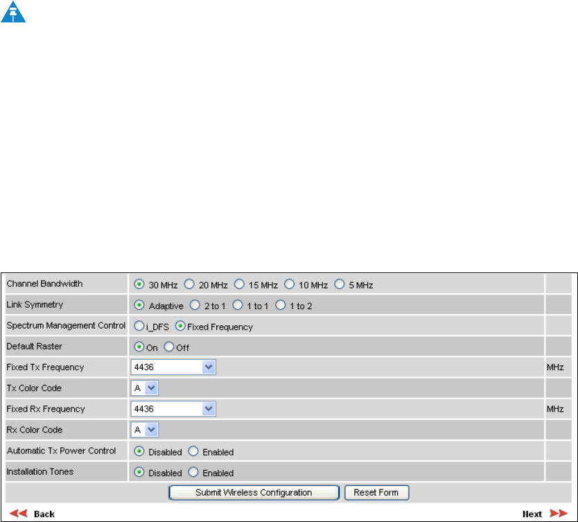
User Guide: PTP 600 Series Installation pages
phn-0896_009v003
Feb 2010 UNDER DEVELOPMENT 6-65
Tx Color Code, Rx Color Code
The Tx Color Code and Rx Color Code attributes need only be considered when the
unit is installed in a dense network of synchronized PTP 600 units and where some of
the PTP 600 units are operating on the same frequency. In this case, the value would
normally be derived by a network radio planner. In all other cases, it is strongly
recommended that this attribute is left at the default value of "A".
NOTE
The value of Tx Color Code MUST always match the value of Rx Color Code
at the other end of the link.
Automatic Tx Power Control
Leave this attribute at the default setting ‘Disabled’.
Installation Tones
Where the use of audio installation tones is not required, this control allows the
installer to optionally disable the tone generator during the installation process.
Figure 6-32 Step 2: Wireless Configuration page (extract) for fixed frequency
Submit wireless configuration
Once the installer is satisfied with the wireless configuration options then the Submit
Wireless Configuration button or the Next link should be clicked.
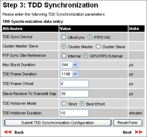
Installation pages Chapter 6 Operation
phn-0896_009v003
6-66 UNDER DEVELOPMENT Feb 2010
TDD synchronization configuration
TDD synchronization is enabled and configured using the install wizard during the
installation process of the link.
TDD synchronization enable
To enable TDD Synchronization, set the TDD Synchronization Mode attribute to
‘Enabled’ (Figure 6-31).
When TDD Synchronization is enabled, the following restrictions apply:
• Ranging Mode and Target Range are disabled.
• Link Symmetry is forced to ‘1:1’ operation only.
TDD synchronization configuration
When TDD Synchronization is enabled, there is an extra installation screen (“TDD
Synchronization”, Figure 6-33).
Figure 6-33 Step 3: TDD Synchronization page
User Guide: PTP 600 Series Installation pages
phn-0896_009v003
Feb 2010 UNDER DEVELOPMENT 6-67
The data required to populate this screen is available in PTP LINKPlanner v1.4.
The TDD Synchronization screen provides the following controls:
TDD Sync Device
Select the timing device that is to be used for TDD synchronization.
Cluster Master Slave
Only displayed when TDD Sync Device is set to ‘PTPSYNC’.
Select the position that this ODU will occupy in the TDD synchronization cluster.
‘Cluster Master’ is the first ODU in the synchronization chain. ‘Cluster Slave’ is the
second or subsequent ODU in the chain.
PTP Sync Site Reference
Only displayed when TDD Sync Device is set to ‘PTPSYNC’.
Select the timing reference source for PTP-SYNC. ‘Internal’ means standalone
operation with no external timing reference. ‘GPS/1PPS External means that an
external GPS receiver will provide a 1 pps timing reference.
Max Burst Duration
The maximum duration of the burst opportunity. Select a value in the range 726 to
2176 microseconds.
TDD Frame Duration
Select a value in the range 1730 to 6410 microseconds.
TDD Frame Offset
The delay of the start of the TDD frame from the epoch of the external timing
reference. This permits the design of synchronized networks in which the phase of the
TDD frame is independent from the fundamental master/slave function. This change
allows more flexibility in selecting the location of master ODUs. Enter a value in the
range from zero to one microsecond less than the TDD Frame Duration.
Slave Receive To Transmit Gap
The duration of the gap between receive and transmit at the slave ODU.
TDD Holdover Mode
(Master only). Two values: “Strict” and “Best Effort”. If a PTP 600 master ODU is
configured for a TDD Holdover Mode set to “Strict”, then it will not transmit when
synchronization is lost. On the other hand, a link configured for TDD Holdover Mode
set to “Best Effort” will synchronize when a reference signal is available, but will
otherwise use best efforts to operate in unsynchronized fashion.
Installation pages Chapter 6 Operation
phn-0896_009v003
6-68 UNDER DEVELOPMENT Feb 2010
TDD Holdover Duration
(Master only). Default value 10 minutes, maximum 60 minutes. Specifies duration of
holdover period following loss of the external timing reference for TDD
synchronization.
User Guide: PTP 600 Series Installation pages
phn-0896_009v003
Feb 2010 UNDER DEVELOPMENT 6-69
Installation step 3 - confirm configuration
Step 3 of the installation process requires the installer to confirm the wireless
configuration parameters. Figure 6-34 is an example of the Confirm Configuration
screen. The screen contents vary depending upon the product variant and
configuration options selected.
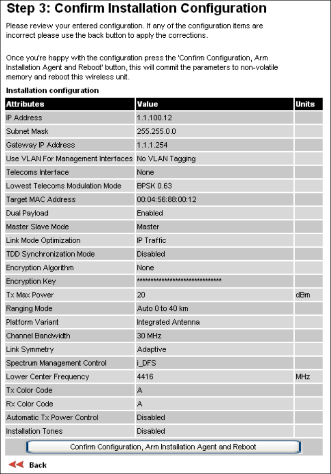
Installation pages Chapter 6 Operation
phn-0896_009v003
6-70 UNDER DEVELOPMENT Feb 2010
Figure 6-34 Step 3: Confirm Installation Configuration page
If the settings are correct and appropriate, click the Confirm Configuration, Arm
Installation and Reboot button. The user will now be prompted to confirm the action
(Figure 6-35).
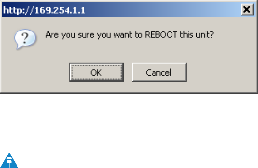
User Guide: PTP 600 Series Installation pages
phn-0896_009v003
Feb 2010 UNDER DEVELOPMENT 6-71
Figure 6-35 Reboot confirmation pop up
All the attributes are committed to non-volatile memory. Immediately following the
write to non-volatile memory the unit is reset.
NOTE
If you have changed the Ethernet parameters you must reconnect using the
correct network and address settings.
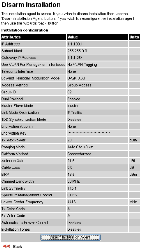
Installation pages Chapter 6 Operation
phn-0896_009v003
6-72 UNDER DEVELOPMENT Feb 2010
Disarm installation
Figure 6-36 is an example of the Disarm Installation screen. The screen contents vary
depending upon the product variant and configuration options selected.
Figure 6-36 Disarm Installation page
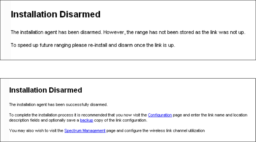
User Guide: PTP 600 Series Installation pages
phn-0896_009v003
Feb 2010 UNDER DEVELOPMENT 6-73
When Section Installation step 3 - confirm configuration on page 6-69 is complete, the
installation is armed and rebooted. Pressing the “Disarm Installation Agent” button
completes the installation process and the audible installation tone will be switched
off. If the installer wishes to modify the installation configuration then the ‘Back’ link
can be used to access the installation wizard steps described above.
The installation process is completed when both ends of the link are ‘disarmed’.
After disarming the wireless link the user is presented with one of two possible
configuration pages, see Figure 6-37 and Figure 6-38. The screen presents hyperlinks
to the main configuration and spectrum management pages.
Figure 6-37 Optional post disarm configuration 1
Figure 6-38 Optional post disarm configuration 2
After installation the system administrator may wish to modify the wireless units
descriptive configuration (link name and link location). In addition the system
administrator may wish to change the spectrum management configuration of the
wireless unit, or look at the analysis of the 5.8 GHz spectrum to see if the automatic
channel selection is appropriate for the system administrator’s network. It is also
recommended that a backup copy of the wireless units configuration is taken.
Hyperlinks are provided on the post disarm page for ease of use.
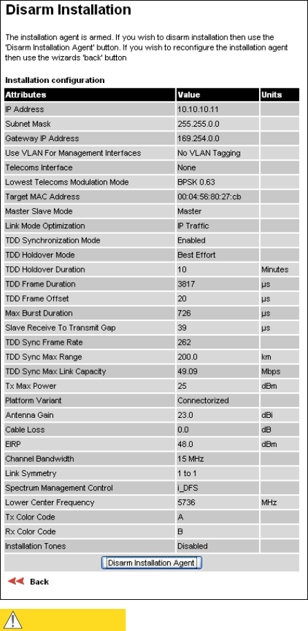
Installation pages Chapter 6 Operation
phn-0896_009v003
6-74 UNDER DEVELOPMENT Feb 2010
Disarm ODU following TDD synchronization configuration
Figure 6-39 Disarm following TDD synchronization
CAUTION
In a synchronized network, links MUST be configured separately before bringing the
whole network up.
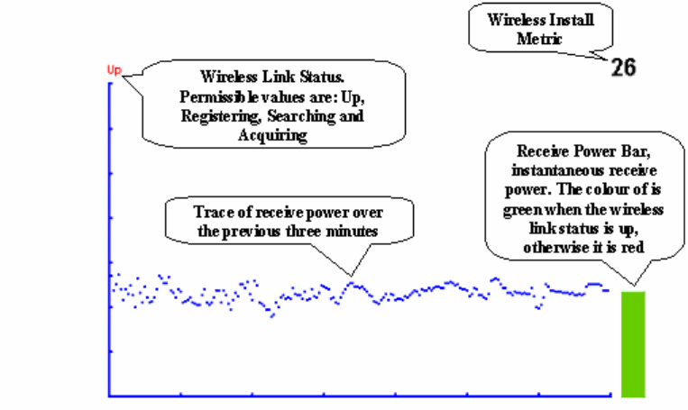
User Guide: PTP 600 Series Installation pages
phn-0896_009v003
Feb 2010 UNDER DEVELOPMENT 6-75
Graphical install
To aid the installation of wireless links two graphical installation aids have been
introduced in this 600 Series system version.
• A PDA installation screen
• A larger installation screen available from the main HTTP management interface.
The design of the installation screen has been deliberately kept simple and
uncluttered. An example of the installation screen is shown in Figure 6-40. Both the
PDA and the large format installation screen have the same content and only differ in
size. The PDA installation screen is 232 by 220 pixels to be compatible with the typical
size of a PDA screen.
Figure 6-40 Graphical installation screen
The screen displays the receive power over the last three minutes. This will allow the
installer to slowly sweep the antenna during installation and monitor the variation in
signal strength with angular position. The screen automatically refreshes every three
seconds.
Installation pages Chapter 6 Operation
phn-0896_009v003
6-76 UNDER DEVELOPMENT Feb 2010
The screen also displays the current state of the wireless link in two ways. First, the
actual state of the wireless link is written in the top left corner of the screen. The
instantaneous receive power bar also encodes the state of the wireless link using
green to signify that the wireless link is up and red for all other states.
For the more technically, aware the installation metric is simply the instantaneous
receive power in dBm + 100.
The PDA installation tool is accessed via a hidden URL http://<ip-address>/pda.cgi. It
should be noted that this link is only available after the user has logged in as system
administrator.
The large screen version of the graphical user interface is available as a submenu
option of the installation wizard.
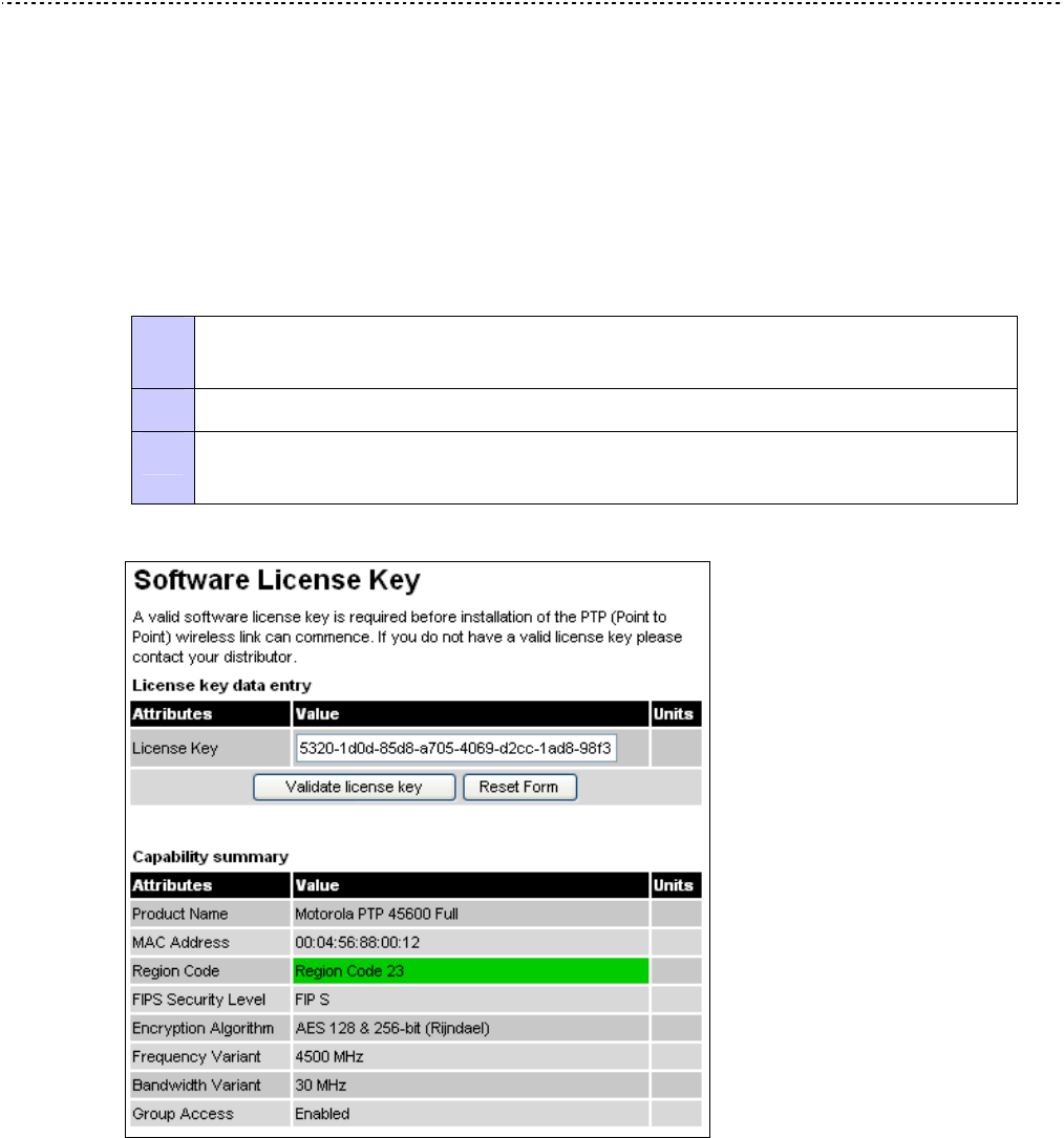
User Guide: PTP 600 Series Upgrading the PTP 600
phn-0896_009v003
Feb 2010 UNDER DEVELOPMENT 6-77
Upgrading the PTP 600
Checking capability summary
Perform this task to check that the currently licensed capabilities (security level,
encryption and group access) of the PTP 600 meet the operator’s requirements.
To check the capability summary, proceed as follows:
Procedure 6-1 Check capability summary
1 From the left hand menu, select License Key. The Software License Key page is
displayed (Figure 6-41).
2 Check the attributes in the Capability summary section (Table 6-8).
3 If the current capabilities do not meet the operator’s requirements, then
determine the new requirements.
Figure 6-41 Software License Key page

Upgrading the PTP 600 Chapter 6 Operation
phn-0896_009v003
6-78 UNDER DEVELOPMENT Feb 2010
Table 6-8 Capability summary attributes
Attribute Meaning
Product Name The name of the PTP 600 product variant.
MAC Address The MAC address of the PTP 600.
Region Code The region code prohibits the wireless unit from
operating outside the regulated limits. An invalid region
code indicates a corrupted license key.
FIPS Security Level The maximum configurable security level.
Encryption Algorithm The encryption algorithms available for use at the
wireless interface of the ODU. Encryption algorithm and
keys must be the same at BOTH ends of the link for it to
function correctly. This attribute is only displayed if the
current license key permits encryption.
Frequency Variant Frequency variant of the wireless unit.
Bandwidth Variant Bandwidth variant of the wireless unit.
Group Access Indicates whether or not group access is enabled.

User Guide: PTP 600 Series Upgrading the PTP 600
phn-0896_009v003
Feb 2010 UNDER DEVELOPMENT 6-79
Using access keys to generate a new license key
The PTP 600 is supplied with a factory default license key. Perform this task to
generate a new license key to activate new licensed capabilities (security level,
encryption or group access).
Before starting this task, perform Checking capability summary on page 6-77.
To generate a new license key, proceed as follows:
Procedure 6-2 Use an access key to generate a license key
1 Purchase the required new capabilities from the Motorola authorized Point-To-Point
dealer who supplied the PTP 600 link.
The dealer will supply one or more access keys.
2 Go to the PTP web support page at http://www.motorola.com/ptp/support and select
Key Generator. The PTP License Key Generator form should be displayed.
3 Enter the required details, including the access keys supplied by the dealer.
4 Submit the web form.
The PTP License Key Generator will respond with the new license key.
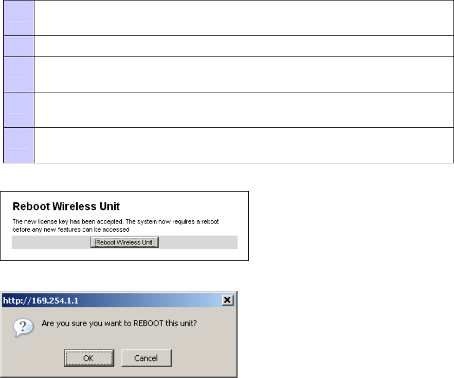
Upgrading the PTP 600 Chapter 6 Operation
phn-0896_009v003
6-80 UNDER DEVELOPMENT Feb 2010
Entering a license key
Perform this task to enter a new license key (when upgrading licensed capabilities).
Before starting this task, ensure that the license key is available. If it is necessary to
upgrade the licensed capabilities of an existing unit, then perform the following tasks
first:
• Checking capability summary on page 6-77
• Using access keys to generate a new license key on page 6-79
To upgrade the unit to a new license key, proceed as follows:
Procedure 6-3 Upgrade unit to a new license key
1 From the left hand menu, select License Key. The Software License Key page is
displayed (Figure 6-41).
2 Enter the new License Key.
3 Select Validate license key. If the license key is valid, the Reboot Wireless Unit
dialog is displayed (Figure 6-42).
4 Select Reboot Wireless Unit. The Reboot Confirmation dialog is displayed (Figure
6-43).
5 Select OK. The reboot progress message is displayed. On completion, the unit
restarts with the new license key.
Figure 6-42 Reboot Wireless Unit dialog
Figure 6-43 Reboot Confirmation dialog

User Guide: PTP 600 Series Upgrading the PTP 600
phn-0896_009v003
Feb 2010 UNDER DEVELOPMENT 6-81
Saving and restoring system configuration
The save and restore feature allows the system administrator to save and restore the
operational configuration of the units. Motorola recommends that the configuration
should be saved immediately after a successful link installation and immediately before
a software upgrade. In the unlikely event that a unit has to be replaced in the field, the
replacement unit can be reconfigured by restoring the saved configuration file.
Saving the configuration file
Perform this task to save the operational configuration of the units.
To save the configuration file, proceed as follows:
Procedure 6-4 Save configuration file
1 From the left hand menu, select Configuration, Save And Restore. The Save &
Restore Configuration page is displayed (Figure 6-44).
2 Select Save Configuration File.
3 Save the configuration file to a PC hard drive.
The configuration file format is:
MAC-mm-mm-mm_IP-iii-iii-iii-iii.cfg
Where: Is:
mm-mm-mm MAC address of unit
iii-iii-iii-iii IP address of unit.
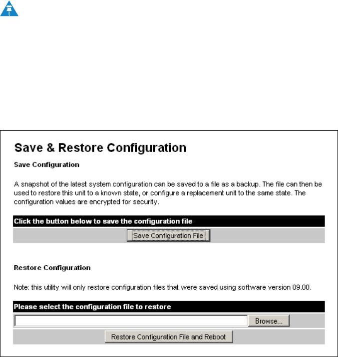
Upgrading the PTP 600 Chapter 6 Operation
phn-0896_009v003
6-82 UNDER DEVELOPMENT Feb 2010
NOTE
Internet Explorer inspects the content of any downloadable file and decides
whether to treat the file as ASCII or binary. As a result of this feature,
Internet Explorer always treats the configuration file as ASCII and attempts
to display it instead of downloading it. Firefox makes no such assumption.
Figure 6-44 Save & Restore Configuration page

User Guide: PTP 600 Series Upgrading the PTP 600
phn-0896_009v003
Feb 2010 UNDER DEVELOPMENT 6-83
Restoring the configuration file
Perform this task to restore the operational configuration of the unit.
Before starting this task, ensure that:
• The configuration file of the old (faulty) unit has been saved.
• The new (replacement) unit has been installed.
• The license key of the old unit has been entered in the new unit.
To restore the configuration file, proceed as follows:
Procedure 6-5 Restore configuration file
1 From the left hand menu, select Configuration, Save And Restore. The Save &
Restore Configuration page is displayed (Figure 6-44).
2 Select Browse and navigate to the PC folder containing the saved configuration file
(.cfg).
3 Select Restore Configuration File and Reboot.
4 Select OK to confirm the restore.
The configuration file is uploaded and used to reconfigure the new unit to the same
state as the old unit. On completion, the unit reboots.

Upgrading the PTP 600 Chapter 6 Operation
phn-0896_009v003
6-84 UNDER DEVELOPMENT Feb 2010
Upgrading PTP 600 software
Perform this task to upgrade the units to a new version of PTP 600 operational
software.
CAUTION
Ensure that the remote end of the link is upgraded first using the wireless
connection, and then the local end can be upgraded. Otherwise, the remote
end may not be accessible.
CAUTION
Ensure that the correct units are upgraded, as units cannot be downgraded
afterwards.
NOTE
Before performing a software upgrade, save the configuration as described
in Saving and restoring system configuration on page 6-81. In the unlikely
event that a unit has to be replaced in the field, the replacement unit can be
reconfigured by restoring the saved configuration file.
To upgrade the software, proceed as follows:
Procedure 6-6 Upgrade software
1 Download and save the new software image (PTP 600-nn-mm.dld2) from
http://www.motorola.com/ptp/support.
2 From the left hand menu, select Software Upgrade. The Software Upgrade page is
displayed (Figure 6-45).
3 Select Browse. Navigate to the folder containing the downloaded software image
and select Open.
4 Select Upload Software Image. The Software Upgrade Confirmation page is
displayed (Figure 6-46). If the upgrade is taking the ODU into or out of FIPS mode,
an additional warning is displayed stating that the upgrade will cause automatic
erasure of the critical security parameters (CSPs).
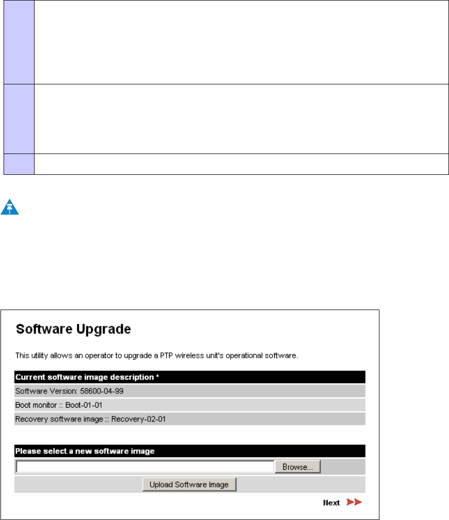
User Guide: PTP 600 Series Upgrading the PTP 600
phn-0896_009v003
Feb 2010 UNDER DEVELOPMENT 6-85
5 Select Program Software Image into Non-Volatile Memory. The Progress
Tracker page is displayed (Figure 6-47). The upgrade process should not be
interrupted, as this can result in a corrupt main software image, which will result in
the recovery image been booted at the next reset cycle.
On completion, the Software Upgrade Complete page is displayed (Figure 6-48).
6 Select Reboot Wireless Unit. Select OK to confirm (Figure 6-49). The unit reboots
with the new software installed.
The reboot process will take up to 120 seconds. During this time it will not be
possible to communicate with the unit.
7 After the reboot, check that the required software image is loaded and running.
NOTE
If communication with the unit is not restored after 120 seconds , this could
indicate a problem with the memory update process. If this happens, enter
“Recovery Mode” as described in Using recovery mode on page 7-20.
Figure 6-45 Software Upgrade page
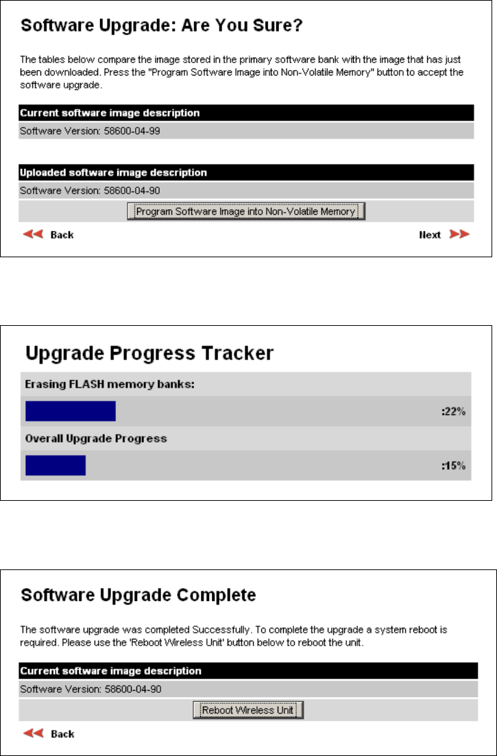
Upgrading the PTP 600 Chapter 6 Operation
phn-0896_009v003
6-86 UNDER DEVELOPMENT Feb 2010
Figure 6-46 Software Upgrade Confirmation page
Figure 6-47 Upgrade Progress Tracker
Figure 6-48 Software Upgrade Complete page
User Guide: PTP 600 Series Upgrading the PTP 600
phn-0896_009v003
Feb 2010 UNDER DEVELOPMENT 6-87
Figure 6-49 Reboot confirmation pop up
File name style for FIPS validated software
FIPS validated software images are indicated by a FIPS- prefix to the file name, for
example: FIPS-PTP600-08-50.DLD2.
Upgrading the PTP 600 Chapter 6 Operation
phn-0896_009v003
6-88 UNDER DEVELOPMENT Feb 2010
Remote software upgrade by TFTP
This section describes how to upgrade the PTP 600 software remotely using Trivial
FTP (TFTP) triggered by SNMP.
To perform a remote software upgrade, follow this procedure:
1. Set tFTP attibutes as described in Setting tFTP attributes on page 6-88.
2. Monitor tFTP attributes as described in Monitoring tFTP attributes on page 6-
89.
3. When the upgrade is complete, reboot the ODU to run the newly loaded
software image as described in Reboot on page 7-27.
Setting tFTP attributes
Set the following tFTP attributes:
tFTPServerIPAddress
This is the IP address of the TFTP server from which the TFTP software upgrade file
Name will be retrieved.
For example, to set the TFTP server IP address for unit 10.10.10.10 to 10.10.10.1,
enter this command:
snmpset_d.exe -v 2c -c public 10.10.10.10 .iso.3.6.1.4.1.17713.1.9.5.0 a
10.10.10.1
tFTPServerPortNumber
This setting is optional. The port number of the TFTP server from which the TFTP
software upgrade file name will be retrieved (default=69).
tFTPSoftwareUpgradeFileName
This is the filename of the software upgrade to be loaded from the TFTP server.
For example, to set the TFTP software upgrade filename on 10.10.10.10 to "B1095.dld", enter this
command:
snmpset_d.exe -v 2c -c public 10.10.10.10 .iso.3.6.1.4.1.17713.1.9.7.0 s
B1095.dld
tFTPStartSoftwareUpgrade
Write '1' to this attribute to start the TFTP software upgrade process. The attribute
will be reset to 0 when the upgrade process has finished.
User Guide: PTP 600 Series Upgrading the PTP 600
phn-0896_009v003
Feb 2010 UNDER DEVELOPMENT 6-89
For example, enter this command:
snmpset_d.exe -v 2c -c public 10.10.10.10 .iso.3.6.1.4.1.17713.1.9.8.0 i
1
Monitoring tFTP attributes
Monitor the values of the following tFTP attributes:
tFTPSoftwareUpgradeStatus
This is the current status of the TFTP software upgrade process. Values:
• idle(0)
• uploadinprogress(1)
• uploadsuccessfulprogrammingFLASH(2)
• upgradesuccessfulreboottorunthenewsoftwareimage(3)
• upgradefailed(4).
For example, enter this command:
snmpget_d.exe -v 2c -c public 10.10.10.10 .iso.3.6.1.4.1.17713.1.9.9.0
tFTPSoftwareUpgradeStatusText
This describes the status of the TFTP software upgrade process, including any error
details.
For example, enter this command:
snmpget_d.exe -v 2c -c public 10.10.10.10 .iso.3.6.1.4.1.17713.1.9.10.0
tFTPSoftwareUpgradeStatusAdditionalText
This is used if tFTPSoftwareUpgradeStatusText is full and there are more than 255
characters to report. It contains additional text describing the status of the TFTP
software upgrade process, including any error details.
For example, enter this command:
snmpget_d.exe -v 2c -c public 10.10.10.10 .iso.3.6.1.4.1.17713.1.9.11.0

Managing security Chapter 6 Operation
phn-0896_009v003
6-90 UNDER DEVELOPMENT Feb 2010
Managing security
Configuring user accounts
Perform this task to ensure that user access to the ODU is controlled in accordance
with the network operator’s security policy. The following user account options may be
configured:
• Best practice passwords.
• Auto logout period.
• Maximum number of login attempts.
• Login attempt lockout period.
• Password expiry period.
• Minimum password change period.
• Identity-based user accounts.
NOTE
To ensure that the ODU is compliant with the security requirements of FIPS
140-2, the above options must all be enabled. For more information, refer to
Configuring FIPS 140-2 mode on page 6-108.
If identity-based user accounts are enabled, this task may only be performed by a
Security Officer.
To set these options, proceed as follows:
Procedure 6-7 Configure user accounts
1 From the left hand menu, select User Accounts. The User Accounts page is
displayed (Figure 6-50).
2 Review and update the user accounts attributes (Table 6-9).
3 If any attributes have been updated, select Submit User Account Updates.
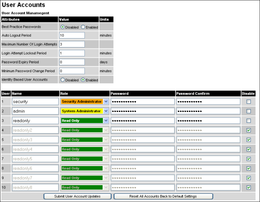
User Guide: PTP 600 Series Managing security
phn-0896_009v003
Feb 2010 UNDER DEVELOPMENT 6-91
Figure 6-50 User Accounts page

Managing security Chapter 6 Operation
phn-0896_009v003
6-92 UNDER DEVELOPMENT Feb 2010
Table 6-9 User accounts attributes
Attribute Meaning
Best Practice Passwords Disable or enable best practice password rules.
When this is enabled, the following rules are applied to all
passwords:
Passwords are case sensitive.
Password must contain at least eight characters.
Passwords must contain at least:
• One uppercase letter.
• One lowercase letter.
• One numeral.
• One special character:
!\"#$%&'()*+,-./:;<=>?@[\]^_`{|}~
Auto Logout Period The time without user activity that elapses before a user is
automatically logged out (minutes).
Maximum Number of
Login Attempts
The maximum number of login attempts (with incorrect
password) that are allowed before a user is locked out.
Login Attempt Lockout
Period
The time that elapses before a locked out user is allowed to log
in again (minutes).
Password Expiry Period The time that elapses before a password expires (days). When
a password has expired, the user is forced to change it.
Minimum Password
Change Period
The minimum time that elapses before a user is allowed to
change a password (minutes).
Identity Based User
Accounts
Enable or disable identity-based user accounts.
When this is disabled, access to the web interface is controlled
by a single system administration password, and the user
account data entry table is disabled.
When this is enabled, the user account data entry table is
enabled. For more information, refer to Creating or updating
identity-based users on page 6-93.

User Guide: PTP 600 Series Managing security
phn-0896_009v003
Feb 2010 UNDER DEVELOPMENT 6-93
Creating or updating identity-based users
Perform this task to allow multiple users (from one to ten) to access the ODU with
different levels of access. There are three defined levels of access: Security Officer,
System Administrator and Read Only.
NOTE
To ensure that the ODU is compliant with the security requirements of FIPS
140-2, identity-based user accounts must be enabled. For more information,
refer to Configuring FIPS 140-2 mode on page 6-108.
If identity-based user accounts are already enabled, this task may only be performed
by a user with role set to Security Officer.
To create or update identity-based user accounts, proceed as follows:
Procedure 6-8 Configure user accounts
1 From the left hand menu, select User Accounts. The User Accounts page is
displayed (Figure 6-50).
2 Set the Identity Based User Accounts attribute to “Enabled” (if it is not already set).
3 Create or update up to 10 user accounts (Table 6-10).
4 If any accounts have been created or updated, select Submit User Account
Updates.
Managing security Chapter 6 Operation
phn-0896_009v003
6-94 UNDER DEVELOPMENT Feb 2010
Table 6-10 Identity-based user accounts attributes
Attribute Meaning
Name Enter a user name.
Role Select a role from the list:
Security Officer
System Administrator
Read Only
NOTE
At least one user must be assigned the Security Officer
role.
Password Enter a password for the user. If Best Practice Passwords are
enabled, all passwords must obey the rules (Table 6-9).
Password Confirm Retype the password to confirm.
Disable Tick the box to disable a user account.
Changing own user password
Perform this task to change a user password.
NOTE
This method is used for any user to change his/her own password. The title
of the page changes between ‘Change System Administrator Password’,
‘Change Security Officer Password’, or ‘Change Read Only Password’.
A security officer can change the passwords of other users using the User
Accounts page, as described in Creating or updating identity-based users on
page 6-93.
From the left hand menu, select Change Password. The Change Password page is
displayed (Figure 6-51). Enter and confirm the new password (the factory default is
blank). If Best Practice Passwords are enabled, the new password must obey the rules
(Table 6-9).
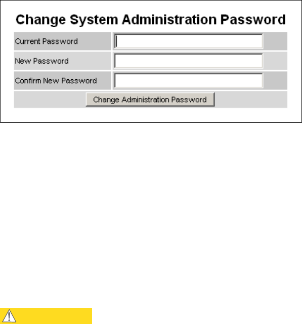
User Guide: PTP 600 Series Managing security
phn-0896_009v003
Feb 2010 UNDER DEVELOPMENT 6-95
Figure 6-51 Change Password page (System Administration example)
The password may contain any combination of characters, up to 31 characters in
length.
Controlling access to the HTTP interface
The attribute HTTP Access Enabled allows a user to stop any access to a unit via
HTTP at the HTTP web interface. The default value for this control is set to ‘Yes’,
which means that the unit can be accessed using the HTTP web interface. If the option
‘No’ is selected, then a warning is displayed as shown in Figure 6-65.
The HTTP interface should be disabled if the HTTPS interface is configured. See
Configuring HTTPS/TLS using the Security Wizard on page 6-98.
CAUTION
If the HTTP, HTTPS, Telnet and SNMP interfaces are all disabled, then it
will be necessary to use the Recovery image to reset IP & Ethernet
Configuration back to factory defaults to re-enable the interfaces.
Controlling access to the Telnet interface
The attribute Telnet Access Enabled allows a user to stop any access to a unit via
the telnet interface. The default value for this control is set to ‘Yes’, which means that
the unit can be accessed using the telnet interface.

Managing security Chapter 6 Operation
phn-0896_009v003
6-96 UNDER DEVELOPMENT Feb 2010
Enabling AES encryption at the wireless interface
AES link encryption is only available to users who have purchased an appropriate
license key. When the license key has been entered, AES link encryption can be
configured via one of the following pages:
• Step 2 of the Installation pages (Figure 6-31).
• Step 5 of the Security Wizard (Figure 6-59).
• The System Configuration page (Figure 6-8).
CAUTION
Configuring link encryption will necessitate a PTP 600 service outage.
Therefore it is recommended that the configuration process be scheduled
during an appropriate period of low link utilization.
To configure AES link encryption from the Step 2: Wireless Configuration page,
proceed as follows:
Procedure 6-9 Configuring AES link encryption
1 Open two browsers, one for each end of the link.
2 Navigate to the Step 2: Wireless Configuration page for each end of the link
(Figure 6-31).
3 At both ends of the link select the same Encryption Algorithm, either ‘AES 128-
bit (Rijndael)’ or ‘AES 256-bit (Rijndael)’ (Figure 6-52).
4 At both ends of the link enter and confirm the same encryption key.
The key consists of 32 or 64 case insensitive hexadecimal characters. The same
key must be entered at both ends of the link. Failure to enter the same key will
cause the link to fail.
5 Submit configuration on both ends of the link, but do not reboot.
6 Reboot both ends of the link (Figure 6-53). The software is designed to allow
five seconds so that a user can command both ends of the link to reboot before
the wireless link drops.
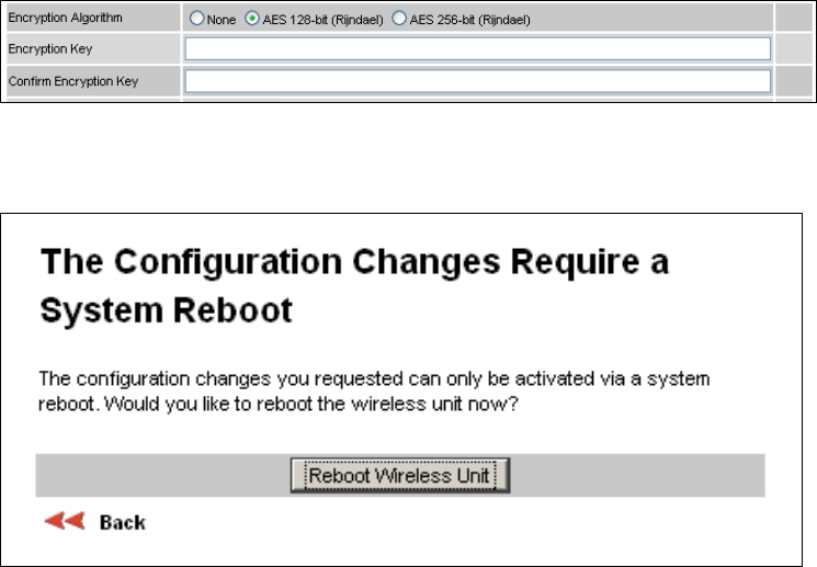
User Guide: PTP 600 Series Managing security
phn-0896_009v003
Feb 2010 UNDER DEVELOPMENT 6-97
Figure 6-52 Step 2: Wireless Configuration page AES attributes
Figure 6-53 Configuration reboot screen

Managing security Chapter 6 Operation
phn-0896_009v003
6-98 UNDER DEVELOPMENT Feb 2010
Configuring HTTPS/TLS using the Security Wizard
Perform this task to review and configure HTTPS/TLS security related parameters.
Current security summary
To review HTTPS/TLS security related parameters, proceed as follows:
Procedure 6-10 HTTPS/TLS using the Security Wizard
1 From the left hand menu, select Security Administration. The Current Security
Summary page is displayed (Figure 6-54).
2 Review the summary.
3 If any updates are required, select Continue to Security Wizard.
The Security Wizard is only available when both of the following conditions are true:
• Identity-based user accounts are disabled, or identity-based user accounts are
enabled and the user's role is Security Officer.
• The wireless unit has a licence key with either 128-bit or 256-bit AES link
encryption enabled.
If these conditions are not both true, the Current Security Summary page prevents
execution of the wizard.
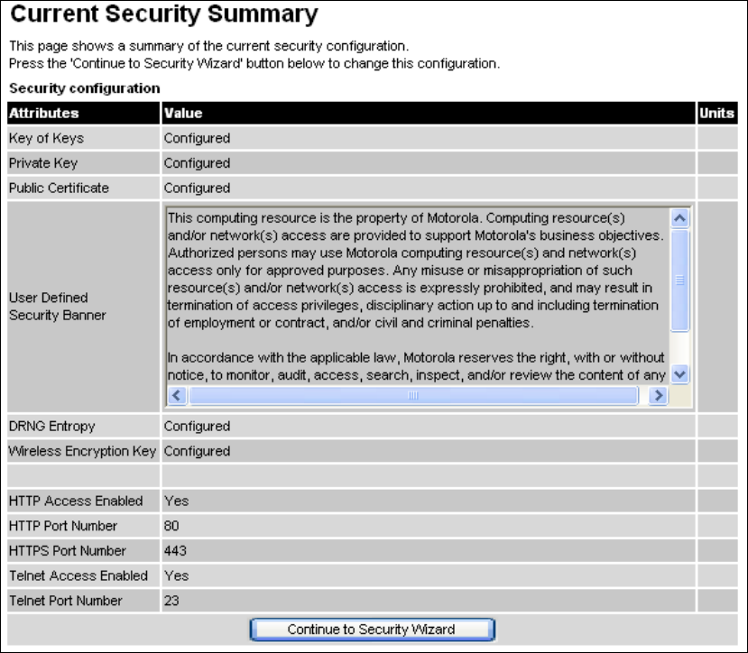
User Guide: PTP 600 Series Managing security
phn-0896_009v003
Feb 2010 UNDER DEVELOPMENT 6-99
Figure 6-54 Current Security Summary page
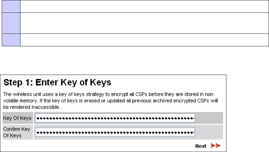
Managing security Chapter 6 Operation
phn-0896_009v003
6-100 UNDER DEVELOPMENT Feb 2010
Step 1: Enter key of keys
The PTP600 uses a key of keys approach to encrypt all critical security parameters
(CSPs). Erasing of the keys of keys will render all CSPs inaccessible.
Generate a key of keys encryption key using a FIPS approved key generator. The key
length is dictated by the prevailing licence key. Licence keys with AES-128 will require
a key of keys of 128-bits. Licence keys with AES-256 will require a key of keys of 256-
bits. The key output should be in ASCII hexadecimal characters.
To enter the key of keys via the Security Wizard, proceed as follows:
Procedure 6-11 Enter the key of keys
1 The Step 1: Enter Key of Keys page is displayed (Figure 6-55).
2 Enter the generated key of keys in both the Key Of Keys and Confirm Key Of Keys
fields. If the two values are not identical, an error message is displayed.
3 Select Next.
Figure 6-55 Step 1: Enter Key of Keys page
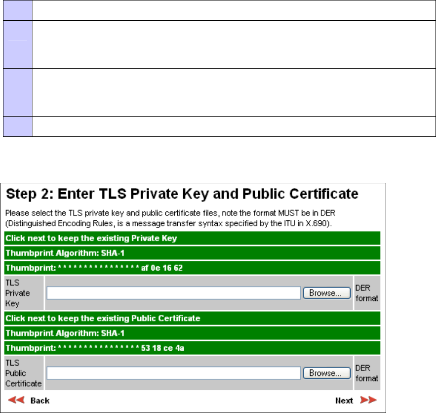
User Guide: PTP 600 Series Managing security
phn-0896_009v003
Feb 2010 UNDER DEVELOPMENT 6-101
Step 2: TLS private key and public certificate
Generate the TLS private key and public certificate in either PKCS#1 or PKCS#5
format. The key pair payload MUST not be encrypted. The certificates must be
encoded in ASN.1 DER format. Supported private key sizes are 1024.
To enter the TLS private key and public certificate via the Security Wizard, proceed as
follows:
Procedure 6-12 Enter TLS private key and public certificate
1 The Step 2: TLS Private Key and Public Certificate page is displayed (Figure 6-56).
2 If a valid TLS private key exists, then an SHA-1 thumbprint of the key is displayed. If
this key is correct, then take no action. Otherwise, select Browse and select the
generated private key file (.der).
3 If a valid TLS public certificate exists, then an SHA-1 thumbprint of the certificate is
displayed. If this certificate is correct, then take no action. Otherwise, select Browse
and select the generated certificate file (.der).
4 Select Next.
Figure 6-56 Step 2: TLS Private Key and Public Certificate page
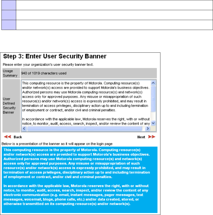
Managing security Chapter 6 Operation
phn-0896_009v003
6-102 UNDER DEVELOPMENT Feb 2010
Step 3: User security banner
The user security banner is displayed every time a user attempts to login to the
wireless unit. Specify the contents of the banner as per the operator’s network
security policy.
To enter the user security banner via the Security Wizard, proceed as follows:
Procedure 6-13 Enter user security banner
1 The Step 3: User Security Banner page is displayed (Figure 6-57).
2 Update the User Defined Security Banner field.
3 Select Next.
Figure 6-57 Step 3: User Security Banner page
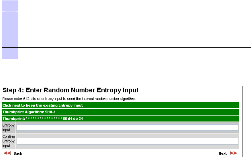
User Guide: PTP 600 Series Managing security
phn-0896_009v003
Feb 2010 UNDER DEVELOPMENT 6-103
Step 4: Random number entropy input
The entropy input is used to seed the TLS random number generator . Generate the
entropy input using a random number generator.
To enter the entropy input via the Security Wizard, proceed as follows:
Procedure 6-14 Enter random number entropy input
1 The Step 4: Random Number Entropy Input page is displayed (Figure 6-58).
2 If valid entropy input exists, then an SHA-1 thumbprint of the input is displayed. If
this input is correct, then take no action. Otherwise, enter the generated input in the
Entropy Input and Confirm Entropy Input fields. If the two values are not identical,
an error message is displayed.
3 Select Next.
Figure 6-58 Step 4: Random Number Entropy Input page
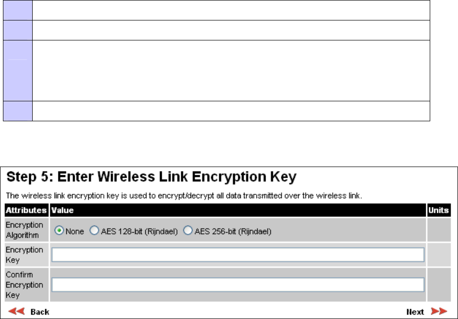
Managing security Chapter 6 Operation
phn-0896_009v003
6-104 UNDER DEVELOPMENT Feb 2010
Step 5: Enter the wireless link encryption key
The wireless link encryption key is used to encrypt all traffic over the PTP600 wireless
link.
To enter the wireless link encryption key via the Security Wizard, proceed as follows:
Procedure 6-15 Enter wireless link encryption key
1 The Step 5: Enter The Wireless Link Encryption Key page is displayed (Figure 6-59).
2 Select the applicable value in the Encryption Algorithm field.
3 If a valid encryption key exists, then an SHA-1 thumbprint of the key is displayed. If
this key is correct, then take no action. Otherwise, enter the generated key in the
Wireless Link Encryption Key and Confirm Wireless Link Encryption Key fields. If the
two values are not identical, an error message is displayed.
4 Select Next.
Figure 6-59 Step 5: Enter The Wireless Link Encryption Key page
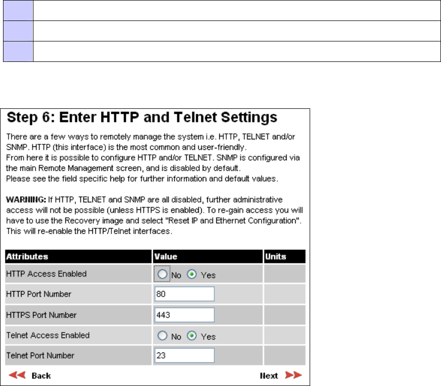
User Guide: PTP 600 Series Managing security
phn-0896_009v003
Feb 2010 UNDER DEVELOPMENT 6-105
Step 6: HTTP and Telnet settings
The PTP 600 can be remotely managed in four ways: HTTPS, HTTP, Telnet or SNMP.
HTTP is the most common and user-friendly. HTTP and Telnet are enabled and
disabled in Step 6 of the Security Wizard. SNMP is configured via the Remote
Management page, and is disabled by default.
To configure HTTP and Telnet via the Security Wizard, proceed as follows:
Procedure 6-16 Configure HTTP and Telnet
1 The Step 6: HTTP and Telnet Settings page is displayed (Figure 6-60).
2 Review and update the HTTP and Telnet attributes (Table 6-11).
3 Select Next.
Figure 6-60 Step 6: HTTP and Telnet Settings page

Managing security Chapter 6 Operation
phn-0896_009v003
6-106 UNDER DEVELOPMENT Feb 2010
Table 6-11 HTTP and Telnet attributes
Attribute Meaning
HTTP Access Enabled When this is set to ‘No’, the unit will not respond to any
requests on the HTTP port. When this is set to ‘Yes’, the unit
will repond to requests on the HTTP port.
Remote management via HTTPS is not affected by this setting.
HTTP Port Number The port number for HTTP access. A value of zero means the
wireless unit uses the default port.
HTTPS Port Number The port number for HTTPS access. A value of zero means the
wireless unit uses the default port.
NOTE
HTTPS access is controlled by license key.
Telnet Access Enabled When this is set to ‘No’, the unit will not respond to any
requests on the Telnet port. When this is set to ‘Yes’, the unit
will repond to requests on the Telnet port.
Telnet Port Number The port number for Telnet access. A value of zero means the
wireless unit uses the default port.
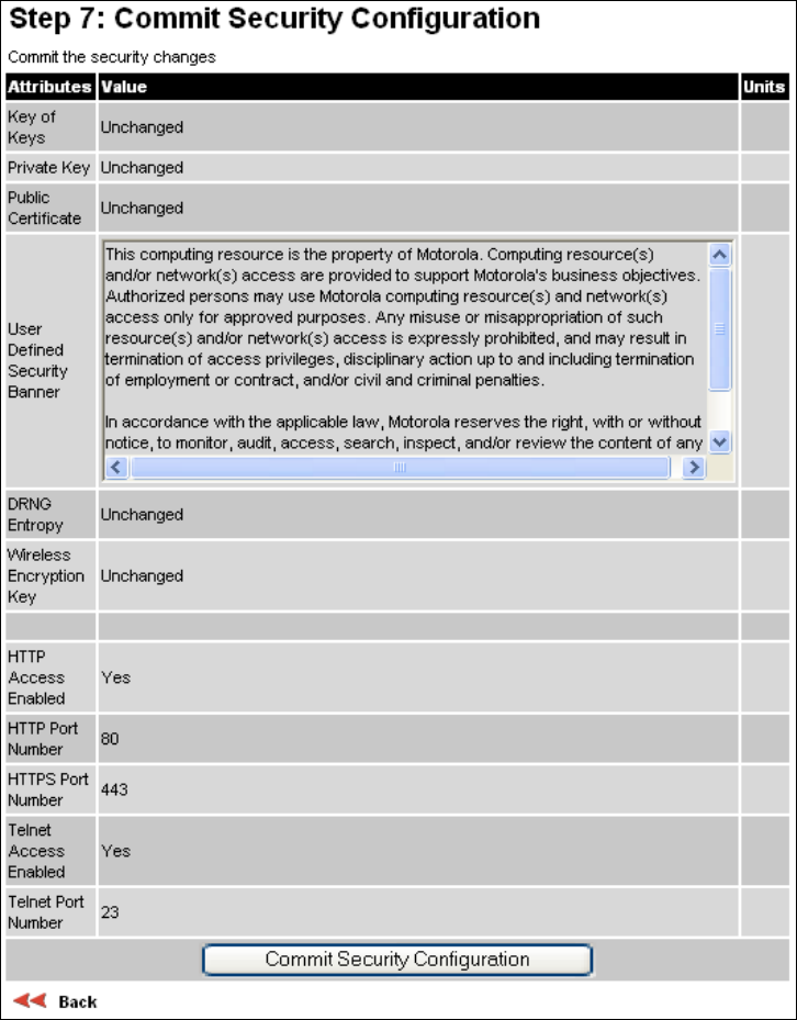
User Guide: PTP 600 Series Managing security
phn-0896_009v003
Feb 2010 UNDER DEVELOPMENT 6-107
Step 7: Commit security configuration
Review all changes that have been made in the Security Wizard (Figure 6-61). To
ensure that the changes take effect, select Commit Security Configuration.
Figure 6-61 Step 7: Commit Security Configuration page
Managing security Chapter 6 Operation
phn-0896_009v003
6-108 UNDER DEVELOPMENT Feb 2010
Configuring FIPS 140-2 mode
Perform this task to place a PTP 600 wireless unit into FIPS 140-2 secure mode. For
more information on FIPS 140-2, refer to FIPS 140-2 on page 1-52.
Before starting this task, ensure that the following resources are available:
• A FIPS approved cryptographic key generator.
• A FIPS approved X509 RSA public / private key pair generator. The required
output format is DER. For more information on DER format, refer to
ITU-T, OSI
networking and system aspects – Abstract Syntax Notation One (ASN.1),
07/2002
.
• A FIPS approved random number generator.
• An HTTPS enabled web browser supporting FIPS approved cipher specifications.

User Guide: PTP 600 Series Managing security
phn-0896_009v003
Feb 2010 UNDER DEVELOPMENT 6-109
To configure the ODU to work in FIPS 140-2 mode, proceed as follows:
Procedure 6-17 Configure FIPS 140-2 operation
1 Inspect the ODU to confirm that silver tamper evident labels are attached (Figure
6-62 and Figure 6-63). If these labels are not present, do not proceed with FIPS
140-2 configuration.
2 Upgrade the ODU software to the latest image containing the FIPS 140-2 security
features (system release 600-08-50 or later). Refer to Upgrading PTP 600 software
on page 6-84.
3 Check the capability summary in the Software License Key page to ensure that the
current license key supports FIPS 140-2. Refer to Checking capability summary on
page 6-77.
4 If the current license key does not support FIPS 140-2:
Obtain an access key and generate a new license key to support FIPS 140-2.
Refer to Using access keys to generate a new license key on page 6-79.
Enter the new license key. Refer to Entering a license key on page 6-80.
5 Configure user accounts to ensure that the ODU is compliant with the security
requirements of FIPS 140-2. Refer to Configuring user accounts on page 6-90.
6 Create at least three identity-based used accounts. Refer to Creating or updating
identity-based users on page 6-93.
7 Log into the web interface as a security administrator user.
8 Run the Security Wizard. Refer to Configuring HTTPS/TLS using the Security
Wizard on page 6-98. The ODU reboots at the end of Security Wizard.
9 The secure web server is now the main management tool for the ODU web interface.
To enter the web interface, use the URL https://169.254.1.1.
10 Go back to the Security Wizard and disabled HTTP and Telnet (if not already
disabled). Refer to Step 6: HTTP and Telnet settings on page 6-105.
The FIPS 140-2 mode is indicated by a distinctive symbol displayed at the top of the
navigation bar in the web-based interface, as shown in Figure 1-17.
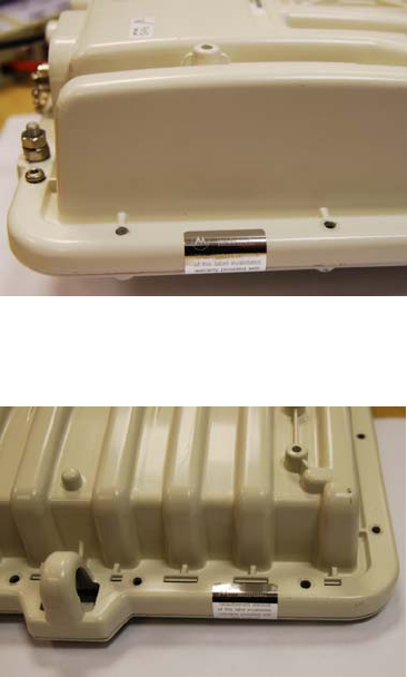
Managing security Chapter 6 Operation
phn-0896_009v003
6-110 UNDER DEVELOPMENT Feb 2010
Figure 6-62 Tamper evident label on side edge of ODU
Figure 6-63 Tamper evident label on top edge of ODU
User Guide: PTP 600 Series Managing security
phn-0896_009v003
Feb 2010 UNDER DEVELOPMENT 6-111
Zeroising critical security parameters
Critical security parameters (CSPs) are as follows:
• Key of keys.
• AES encryption keys for the wireless interface.
• Private key for the HTTPS/TLS interface.
• Entropy value for the HTTPS/TLS interface.
• User account passwords for the web-based interface.
To zeroize the CSPs, select Zeroize CSPs from the menu and then Select Zeroize
CSPs and Reboot Wireless Unit. Confirm the reboot.
Alternatively, select the Zeroise CSPs option in Recovery mode.
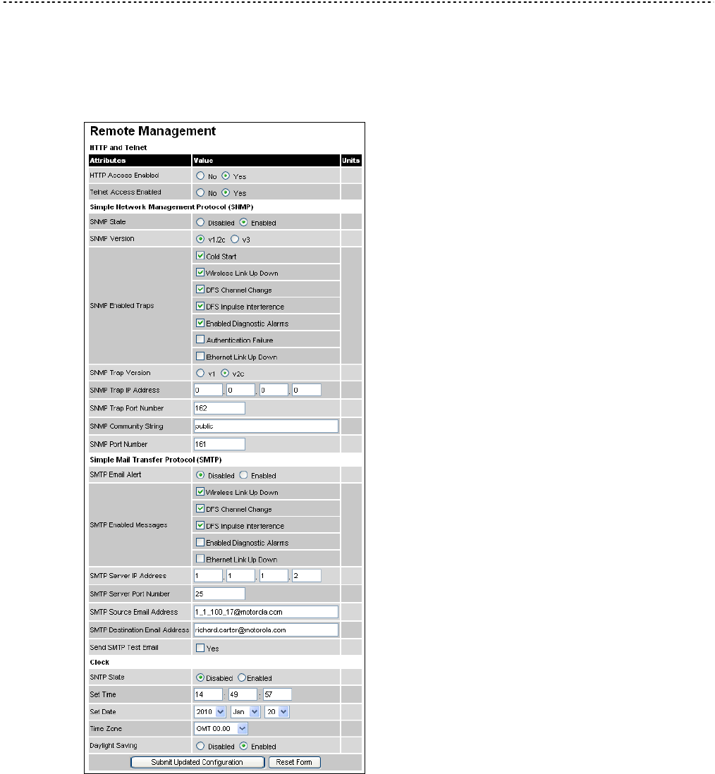
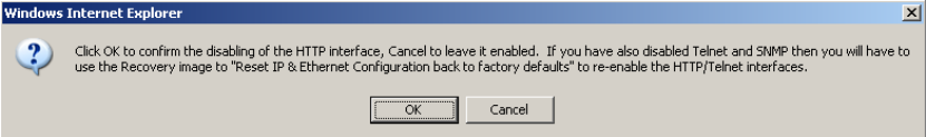
User Guide: PTP 600 Series Managing faults
phn-0896_009v003
Feb 2010 UNDER DEVELOPMENT 6-113
Supported Management Information Bases (MIBs)
The PTP 600 Series SNMP stack currently supports the following MIBs:
• MIB-II, RFC-1213, The PTP 600 Series supports the ‘System Group’ and
‘Interfaces Group’.
• Bridge MIB, RFC-1493, The PTP 600 Series supports the ‘dot1dBase Group’ and
the ‘dot1dBasePortTable Group’.
• PTP 600 Series proprietary MIB
• RFC-2233 (High capacity counter) MIB
• WiMAX MIB
SNMP TRAPs supported:
• Cold Start
• Link Up
• Link Down
• DFS Channel Change
• DFS Impulsive Interference
Figure 6-65 Warning when disabling HTTP interface
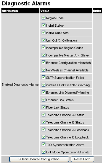
Managing faults Chapter 6 Operation
phn-0896_009v003
6-114 UNDER DEVELOPMENT Feb 2010
Diagnostics alarms
A number of diagnostics alarms have been added to allow SNMP agents to receive
traps and emails if required. These alarms are described in Home page alarm display
on page 6-6. Checking the control “Enabled Diagnostic Alarms” in SNMP and/or SNTP
selects all the alarms shown in Figure 6-66. Users can access the sub-menu
“Diagnostic Alarms” to modify the alarms selected.
Figure 6-66 Diagnostic Alarms page
For a copy of the Motorola proprietary version 1 and version 2 MIB RFCs please
consult the installation CD.

User Guide: PTP 600 Series Managing faults
phn-0896_009v003
Feb 2010 UNDER DEVELOPMENT 6-115
Configuring SNMP notifications
Perform this task to enable the PTP 600 to generate Simple Network Management
Protocol (SNMP) traps.
If SNMP is enabled, then the PTP 600 generates SNMP traps when certain events
occur, and sends the traps to the network SNMP management agent, which notifies
the system administrator.
To configure SNMP notifications, proceed as follows:
Procedure 6-18 Select the SNMP version
1 From the left hand menu, select Remote Management. The Remote Management
page is displayed (Figure 6-64).
2 Update the SNMP attributes (Table 6-12).
3 Select Submit Updated Configuration. The Configuration Change Reboot dialog is
displayed.
4 Select Reboot Wireless Unit. The Reboot Confirmation dialog is displayed
5 Select OK. The reboot progress message is displayed. On completion, the unit
restarts.
Table 6-12 SNMP attributes in the Remote Management page
Attribute Meaning
SNMP State ‘Disabled’ means that SNMP traps are not generated.
‘Enabled’ means that SNMP traps will be generated in
response to selected events, and sent to the network
management system.
SNMP Version Select the SNMP protocol version to be used for SNMP traps.
If ‘v1/2c’ is selected, the SNMP Trap Version, Trap IP Address,
Trap Port Number and Community String attributes are
displayed. If ‘v3’ is selected, these attributes are hidden.
SNMP Enabled Traps Select the events that will generate SNMP traps.
SNMP Trap Version Select protocol version v1 or v2c.

Managing faults Chapter 6 Operation
phn-0896_009v003
6-116 UNDER DEVELOPMENT Feb 2010
Attribute Meaning
SNMP Trap IP Address Enter the IP address that will receive all SNMP traps.
This will normally be the network management system,
but it may be a separate trap receiver.
To disable trap generation, enter 0.0.0.0 in the IP
Address.
SNMP Trap Port
Number
Enter the port number of either the networked SNMP
manager or trap receiver. By convention, the default port
number is 162.
SNMP Community
String
The SNMP community string acts like a password
between the network management system and the
distributed SNMP clients (PTP 800 CMUs). Only if the
community string is configured correctly on all SNMP
entities can the flow of management information take
place. By convention the default value is set to ‘public’.
SNMP Port Number Enter the port that the SNMP agent is listening to for
commands from a management system. By convention,
the default port number is 161.
WiMAX Control Enables and Disables the WiMAX (802.16) MIB. This
control is only displayed when ‘Fixed Frequency’ is
selected during installation.
SMTP (Simple Mail Transport Protocol)
The SMTP client is an alternative method for the PTP 600 Series to alert a system
administrator when there are or have been system errors:
SMTP Email Alert
This attribute controls the activation of the SMTP client.
SMTP Enabled Messages
The SMTP Enabled Messages attribute controls which email alerts the unit will send.
SMTP IP Address
The IP address of the networked SMTP server.
SMTP Port Number
The SMTP Port Number is the port number used by the networked SMTP server. By
convention the default value for the port number is 25.
User Guide: PTP 600 Series Managing faults
phn-0896_009v003
Feb 2010 UNDER DEVELOPMENT 6-117
SMTP Source Email Address
The email address used by the PTP 600 Series to log into the SMTP server. This must
be a valid email address that will be accepted by your SMTP Server.
SMTP Destination Email Address
The email address to which the PTP 600 Series will send the alert messages.
SNTP (Simple Network Time Protocol)
The SNTP client allows the PTP 600 Series to obtain accurate date and time updates
from a networked timeserver. The system time is used for SNMP and event logging.
SNTP State
When enabled, the Remote Management web page permits the following attributes to
be set:
SNTP IP Address
The IP address of the networked SNTP server.
SNTP Port Number
The port number of the networked SNTP server. By convention the default value for
the port number is 123.
SNTP Poll Interval
The period at which the SNTP client polls the server for time correction updates.
Default 1 hour. If for any reason an SNTP poll fails, the client will automatically
perform 3 retries before waiting for the user defined poll period.
Time Zone
The time zone is a fixed offset from GMT that is added to the SNTP time to allow the
expression of time in all geographic time zones.
Daylight Saving
Allows a fixed offset of one hour to be added to the SNTP time in order to reflect the
local daylight saving time.
Managing faults Chapter 6 Operation
phn-0896_009v003
6-118 UNDER DEVELOPMENT Feb 2010
Setting the clock
The PTP 600 Series has a system clock which can be used to supply accurate date and
time information in the absence of a SNTP server. The system clock is battery backed
and will continue to operate for several days if the PTP 600 Series has been switched
off.
SNTP State
If the SNTP State is set to “Disabled”, see Figure 6-64, then the Remote Management
web page allows the following attributes to be set:
Set Time
Shows the current time in 24 hour mode. The three editable fields display hours
minutes and seconds.
Set Date
Displays the current date. The year, month and day can be set using the drop-down
selection boxes.
Time Zone
See Setting the clock on page 6-118.
Daylight Saving
See Setting the clock on page 6-118.
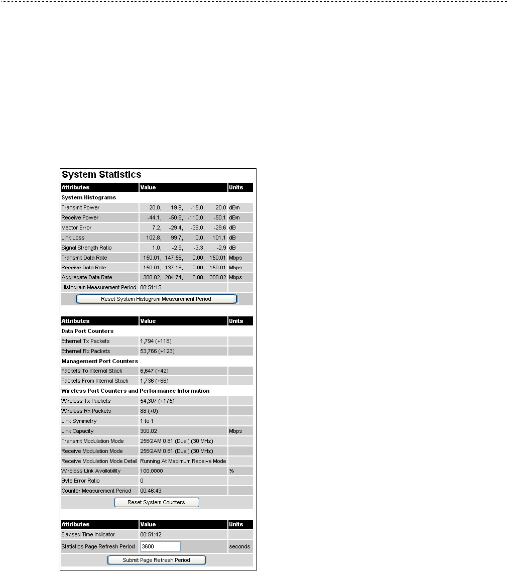
User Guide: PTP 600 Series Managing performance
phn-0896_009v003
Feb 2010 UNDER DEVELOPMENT 6-119
Managing performance
Statistics
The System Statistics page (Figure 6-67) displays some key statistics of the Ethernet
Bridge and the underlying wireless performance.
The numbers in brackets display the number of packets received since the last page
refresh.
Figure 6-67 System Statistics page
Managing performance Chapter 6 Operation
phn-0896_009v003
6-120 UNDER DEVELOPMENT Feb 2010
System histograms
The System Statistics page contains the following fields under System Histograms:
Transmit Power
Receive Power
Vector Error
Link Loss
Signal Strength Ratio
The Signal Strength Ratio is the ratio of the power received by the Vertical /
Horizontal receivers and presented as: max, mean, min, and latest in an histogram
format. The max, min and latest are true instantaneous measurements; the mean is the
mean of a set of one second means. See Histogram data on page 6-18.
Transmit Data Rate
The data rate in the transmit direction, expressed in Mbps and presented as: max,
mean, min, and latest in an histogram format. The max, min and latest are true
instantaneous measurements; the mean is the mean of a set of one second means.
Expected data rates can be found in Data rate calculations on page 4-99.
Receive Data Rate
The data rate in the receive direction, expressed in Mbps and presented as: max,
mean, min, and latest in an histogram format. The max, min and latest are true
instantaneous measurements; the mean is the mean of a set of one second means.
Expected data rates can be found in Data rate calculations on page 4-99.
Aggregate Data Rate
The sum of the data rate in the directions expressed in Mbps and presented as: max,
mean, min, and latest in an histogram format. The max, min and latest are true
instantaneous measurements; the mean is the mean of a set of one second means.
Expected data rates can be found in Data rate calculations on page 4-99.
Histogram Measurement Period
The time over which the system histograms were collected.

User Guide: PTP 600 Series Managing performance
phn-0896_009v003
Feb 2010 UNDER DEVELOPMENT 6-121
NOTE
To reset all histograms and restart the measurement period, select Reset
System Histograms and Measurement Period.
Data port counters
The System Statistics page contains the following fields under Data Port Counters:
Ethernet Tx Packets
This displays the total number of good packets the bridge has sent for transmission by
the local Ethernet interface.
Ethernet Rx Packets
This displays the total number of good packets the bridge has received from the local
Ethernet interface.
Management port counters
The System Statistics page contains the following fields under Management Port
Counters:
Packets To Internal Stack
This displays the total number of good packets the bridge has transmitted to the
internal stack (for example, ARP requests, PING requests, HTTP requests).
Packets From Internal Stack
This displays the total number of good packets the bridge has received from the
internal stack (for example ARP responses, PING replies, HTTP responses).
Wireless port counters and performance information
The System Statistics page contains the following fields under Wireless Port
Counters and Performance Information:
Wireless Tx Packets
This displays the total number of good packets the bridge has sent for transmission by
the wireless interface.
Wireless Rx Packets
This displays the total number of good packets the bridge has received from the
wireless interface.
Managing performance Chapter 6 Operation
phn-0896_009v003
6-122 UNDER DEVELOPMENT Feb 2010
Link Symmetry
Link Symmetry: A ratio that expresses the division between transmit and receive time
in the TDD frame. The first number in the ratio represents the time allowed for the
transmit direction and the second number represents the time allowed for the receive
direction.
Link Capacity
The maximum aggregate data capacity available for user traffic under the current
radio link conditions, assuming the units have been connected using Gigabit Ethernet.
The sum of the displayed Transmit and Receive data rates may be lower than this
figure if the link isn't fully loaded by the current traffic profile.
Transmit Modulation Mode
The modulation mode currently being used on the transmit channel. The number in
brackets after the modulation mode and coding rate string is the effective data rate
available to all MAC layer protocols. List of all the modulation modes can be found in
Data rate calculations on page 4-99, where data rate calculations plots are given for
each available modulation mode.
Receive Modulation Mode
The modulation mode currently being used on the receive channel. The number in
brackets after the modulation mode and coding rate string is the effective data rate
available to all MAC layer protocols. List of all the modulation modes can be found in
Data rate calculations on page 4-99, where data rate calculations plots are given for
each available modulation mode.
Receive Modulation Mode Detail
This supplies the user with information regarding the receive modulation mode in use.
Possible values are:
o “Running at maximum receive mode”
o “Running at user-configured Target Modulation Mode”
o “Restricted because Installation is armed”
o “Restricted because of byte errors on the wireless link”
o “Restricted because a DFS channel change is in progress”
o “Restricted due to the low Ethernet link speed”
o “Limited by the radio conditions”
Wireless Link Availability
Expresses the link availability as a percentage of time since the first successful
registration after a system restart, expressed as a percentage to four decimal places.

User Guide: PTP 600 Series Managing performance
phn-0896_009v003
Feb 2010 UNDER DEVELOPMENT 6-123
Byte Error Ratio
The ratio of detected Byte errors to the total number of bytes since the last system
reboot. This is a true measure of link quality as this measurement is made continually
using null frames when there is no user data to transport.
Counter Measurement Period
The time over which the system counters were collected.
NOTE
To reset all system counters to zero, select Reset System Counters.
Other attributes
The System Statistics page contains the following other fields:
Elapsed Time Indicator
Elapsed time since the last system reboot.
Statistics Page Refresh Period
The statistics page refreshes automatically according to the setting entered here (in
seconds).
NOTE
After updating the Statistics Page Refresh Period field, select Submit Page
Refresh Period.
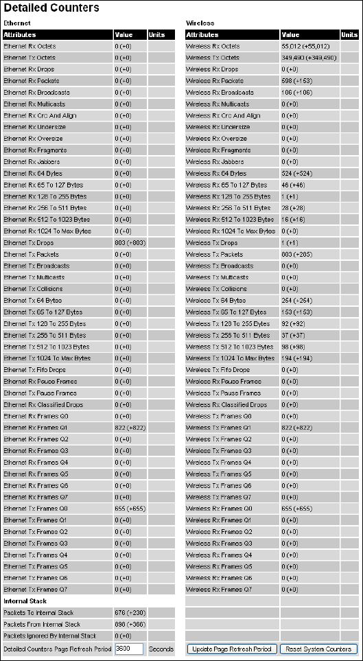
User Guide: PTP 600 Series Managing performance
phn-0896_009v003
Feb 2010 UNDER DEVELOPMENT 6-125
The Detailed Counters page is subdivided into two columns. Column one presents the
detailed statistics for the bridge’s Ethernet interface. Column two relates to the
wireless interface.
The Counters have the following definitions:
Tx & Rx Octets
Total number of octets (bytes) transmitted or received over the interface.
Rx Drops
Total number of frames dropped due to the lack of sufficient capacity in the receive
buffer.
Rx Packets
Total number of packets received by the interface. This includes both good and bad
packets.
Rx Broadcasts
Total number of good broadcast packets.
Rx Multicasts
Total number of good multicast packets.
Rx CRC and Align
Total number of packets with CRC or frame alignment errors.
Rx Undersize
Total number of packets received that are less than 64 bytes and have a valid CRC.
Rx Oversize
Total number of packets received that are greater than the maximum number of bytes
with a valid CRC.
Rx Fragments
Total number of packets that are less than 64 bytes with an invalid CRC (these packet
types are also known as runts).
Rx Jabbers
Total number of packets received that are greater than the maximum number of bytes
with an invalid CRC.
Managing performance Chapter 6 Operation
phn-0896_009v003
6-126 UNDER DEVELOPMENT Feb 2010
Rx 64 Bytes
Total number 64 byte frames received
Rx 65 to 127 Bytes
Total number of frames received in the size range 65 to 127 bytes.
Rx 128 to 255 Bytes
Total number of frames received in the size range 128 to 255 bytes.
Rx 256 to 511 Bytes
Total number of frames received in the size range 256 to 511 bytes.
Rx 512 to 1023 Bytes
Total number of frames received in the size range 512 to 1023 bytes.
Rx 1024 to Max
Total number of frames received in the size range 1024 to Maximum bytes.
Tx Drops
Total number of frames dropped due excessive collisions, late collision and frame
ageing.
Tx Packets
Total number of packets received by the interface. This includes both good and bad
packets.
Tx Broadcasts
Total number of good broadcast packets.
Tx Multicasts
Total number of good multicast packets.
Tx Collisions
Total number frames experiencing collisions.
Tx 64 Bytes
Total number 64 byte frames transmitted
Tx 65 to 127 Bytes
Total number frames transmitted in the size range 65 to 127 bytes.
Tx 128 to 255 Bytes
Total number frames transmitted in the size range 128 to 255 bytes.
User Guide: PTP 600 Series Managing performance
phn-0896_009v003
Feb 2010 UNDER DEVELOPMENT 6-127
Tx 256 to 511 Bytes
Total number frames transmitted in the size range 256 to 511 bytes.
Tx 512 to 1023 Bytes
Total number frames transmitted in the size range 512 to 1023 bytes.
Tx 1024 to Max
Total number frames transmitted in the size range 1024 to Maximum bytes.
Tx FIFO Drops
Total number frames dropped due to lack of capacity in the transmit buffer, for
example when the PTP 600 Series is connected to the local Ethernet at a connection
speed of less than 1 Gbps.
Rx & Tx Frames Q0…Q7
Total number of received or transmitted frames for each Traffic Class (Q0 to Q7).
Rx & Tx Pause Frames
Total number of received or transmitted pause frames (Ethernet interface only).
Packets To Internal Stack
The total number of good packets the bridge has transmitted to the internal stack.
Packets From Internal Stack
The total number of good packets the bridge has received from the internal stack
Packets Ignored By Internal Stack
The total number of bad packets the bridge has transmitted to the internal stack.
Rx Classifier Drops
Total number of received frames dropped due to the application of classifier rules.
Detailed Counters Page Refresh Period
The statistics page refreshes automatically according to the setting entered here (in
seconds).
Managing performance Chapter 6 Operation
phn-0896_009v003
6-128 UNDER DEVELOPMENT Feb 2010
Diagnostics plotter
To further enhance the diagnostic capabilities of the PTP 600 Series, the storage of
link performance histograms has been extended to 31. To optimize RAM (volatile
memory) usage a cascading histogram approach has been adopted. The root histogram
is identical to the histograms in earlier releases of the software, that is data is stored
for one hour at a resolution of one second. Previously, the histograms were simple
cyclic buffers which never stored more that the last one hour of data. The new
cascading histogram approach daisy chains multiple histograms together. When the
first histogram fills up the overflow from the first is used as an input to the next
histogram in line. To optimize memory utilization, a statistical analysis is performed on
the overflow to reduce the amount of data to be stored. In the case of the PTP 600
Series the cascading histograms are defined as:
• Histogram 1: 1 hour at a resolution of 1 second
• Histogram 2: 24 hours at a resolution of 1 minute
• Histogram 3: 30 Days at a resolution of 1 hour
For example, when histogram 1 fills up and starts to overflow the first minute of
overflow is analyzed and the maximum, minimum and mean over that minute are
computed and inserted into histogram 2. When histogram 2 fills up and starts to
overflow the first hour of overflow is analyzed and the maximum, minimum and mean
over that hour is computed and inserted into histogram 3. When histogram 3 starts to
overflow, the overflow data is simply discarded.
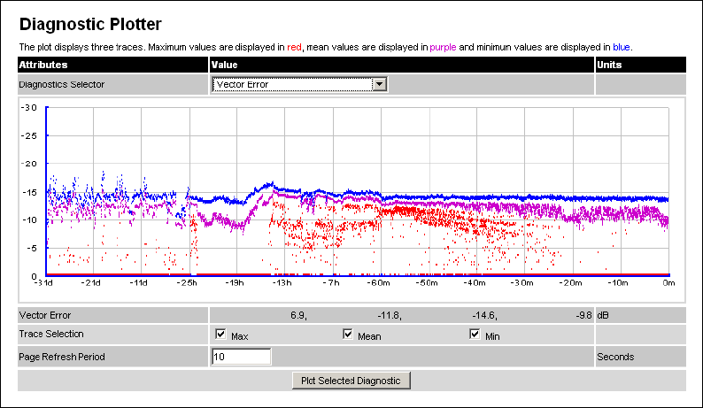
User Guide: PTP 600 Series Managing performance
phn-0896_009v003
Feb 2010 UNDER DEVELOPMENT 6-129
Diagnostic plotter page
New for the PTP 600 Series is the system administration diagnostic plotter facility see
Figure 6-69.
Figure 6-69 Diagnostic Plotter page
The diagnostic plotter allows the system administrator to view the cascading
histogram data in an easily accessible graphical form. The plot always displays three
traces, maximum, minimum and mean by default. The diagnostic selector allows the
user to select the various categories of histogram.
The histograms that are available are:
• Vector Error
• Rx Power
• Tx Power
• Signal Strength Ratio
• Link Loss
• Rx Data Rate
• Tx Data Rate
• Aggregate Data Rate

Managing performance Chapter 6 Operation
phn-0896_009v003
6-130 UNDER DEVELOPMENT Feb 2010
The diagnostic plotter uses a novel time representation in the x-axis which compresses
the timeline of the plot without sacrificing resolution.
The trace selection allows the user to control which traces are plotted.
As with other management pages the page refresh period can be used to interactively
monitor the wireless link.
CSV download
The diagnostics Download page allows the system administrator to download
snapshots of system diagnostics.
Figure 6-70 Generate Downloadable Diagnostics page
The following diagnostics are available:
• Vector Error
• Rx Power
• Tx Power
• Signal Strength Ratio V/H
• Link Loss
• Rx Data Rate
• Tx Data Rate
• Aggregate Data Rate
• Receive SNR
• Rx Gain
All diagnostics are extracted from the associated status and statistics web page
histograms. They are translated in a CSV file containing at most 5784 entries. These
5784 entries comprise 3600 entries for the first hour, 1440 entries for the next 24
hours and 744 entries for the next 31 days.
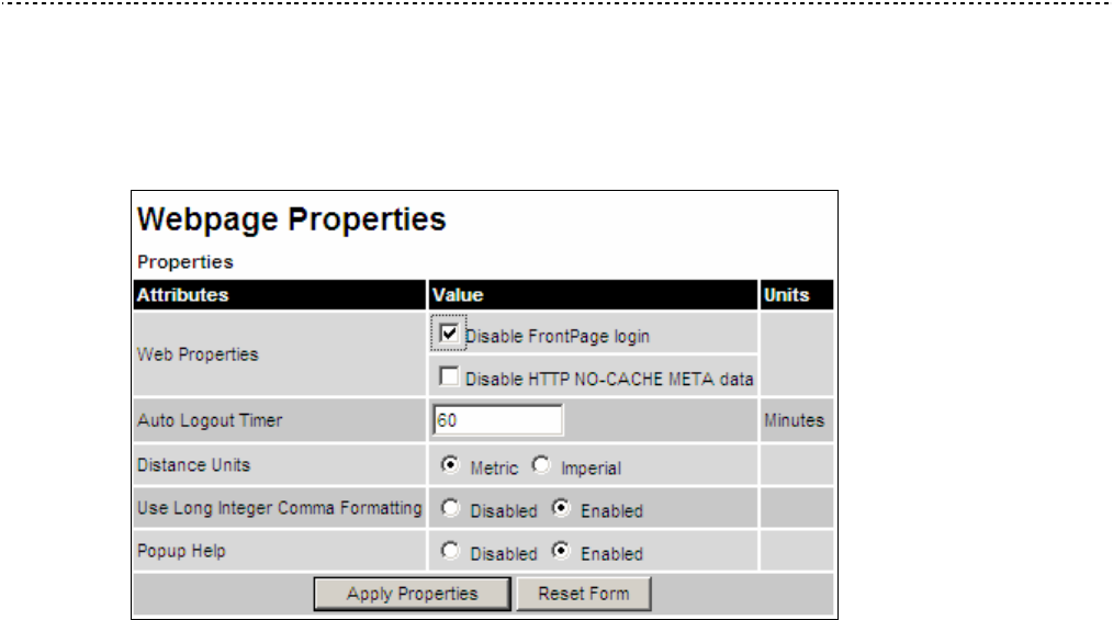
User Guide: PTP 600 Series Properties
phn-0896_009v003
Feb 2010 UNDER DEVELOPMENT 6-131
Properties
The web page properties screen allows the user to configure the web page interface
(Figure 6-71).
Figure 6-71 Webpage Properties page
The Properties page contains the following fields:
WEB Properties: Disable Front Page Login
Allows access to homepage and status page web pages without forcing a login as the
system administrator.
WEB Properties: Disable HTTP NO-CACHE META data
Removes the HTTP NO-CACHE META clause from all dynamically created web pages.
Auto Logout Timer
Configures the time, in minutes, when the system administrator is automatically
logged out if no web page activity is detected.
Distance Units
Swaps the default metric display of distance in to imperial units, for example km to
Miles.
Use Long Integer Comma Formatting
Changes the format of long integers from 1000000 to 1,000,000.
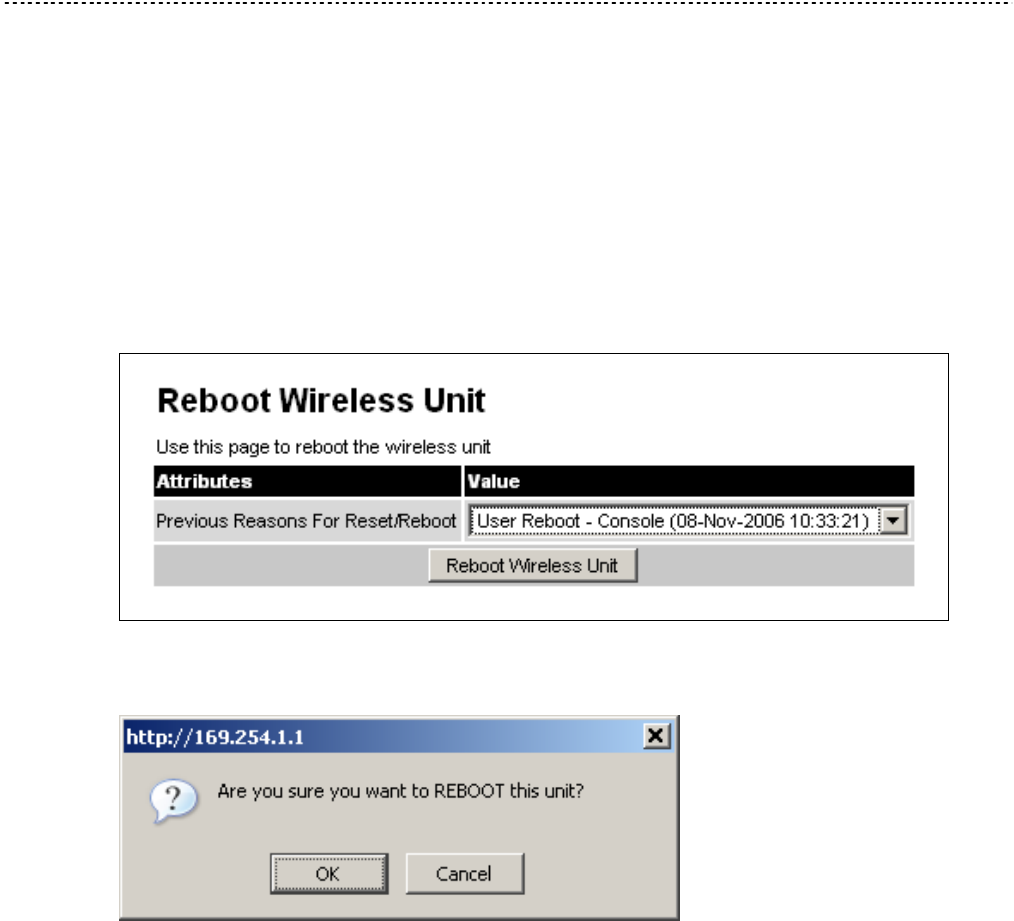
Reboot Chapter 6 Operation
phn-0896_009v003
6-132 UNDER DEVELOPMENT Feb 2010
Reboot
The reboot page allows the system administrator to perform commanded reboots of
the wireless unit. The reboot page also allows the system administrator to view a list of
past reboot reasons. The “Previous Reasons For Reset/Reboot” field has been
implemented as a drop down selection box, where the latest reason for reboot is
located at the top of the list.
If the SNTP service from the remote management section above is active, or the
system time has been set, then the command reboot reason will be accompanied by
the date and time at which the reboot occurred.
Figure 6-72 Reboot Wireless Unit page
Figure 6-73 Reboot confirmation pop up

Chapter 7
phn-0896_009v003
Feb 2010 UNDER DEVELOPMENT 7-1
Chapter 7 Troubleshooting
. . . . . . . . . . . . . . . . . . . . . . . . . . . . . . . . . . . . . . . . . . . . . . . . . . . . . . . . . . . .
.
.
.
.
This section provides instructions for identifying and correcting faults in a PTP 600
link.
Perform the following procedures either on a newly installed link, or on an operational
link if communication is lost:
Procedure 7-1 Troubleshooting (fault finding)
1 Test the hardware at one end of the link, as described in Test link end
hardware on page 7-2.
2 Test the hardware at the other end of the link, as described in Test link end
hardware on page 7-2.
3 Test the radio link, as described in Test radio link on page 7-17.
4 If an installation has been struck by lightning, see Lightning strike on page
7-19.
5 If an ODU has entered recovery mode, see Using recovery mode on page 7-
20.

Test link end hardware Chapter 7 Troubleshooting
phn-0896_009v003
7-2 UNDER DEVELOPMENT Feb 2010
Test link end hardware
Before testing link end hardware, confirm that all outdoor drop cables, that is those
that connect the ODU or GPS receiver (if installed) to equipment inside the building,
are of the supported Superior Essex cable type, as defined in Outdoor connections on
page 1-15.
When the link end hardware (PIDU Plus, LPU, ODU and cabling) has been installed,
test it by following this procedure:
Procedure 7-2 Testing link end hardware
1 Apply mains or battery power to the PIDU Plus. The green Power LED should
illuminate continuously.
2 After 45 seconds, the orange Ethernet LED should be observed starting with
10 slow flashes.
3 Connect the CAT5e cable from the LAN port of the PIDU Plus to the network.
The Ethernet LED should blink randomly as traffic passes through.
4 If the Power and Ethernet LEDs do not illuminate correctly, test the link end
as described in the flowchart (Figure 7-1) and detailed test procedures that
follow.
5 If a UltraSync GPS synchronization unit has been installed, but one or more of
its status LEDs are not illuminated, refer to Test UltraSync GPS receiver on
page 7-16.

User Guide: PTP 600 Series Test link end hardware
phn-0896_009v003
Feb 2010 UNDER DEVELOPMENT 7-3
Figure 7-1 Link end hardware test flowchart #1
Yes
No
Yes
Did Ethernet LED flash
10 times?
Start
Is Ethernet activity
normal?
Is Ethernet connection
1000 BaseT?
Is the green power LED
on solid?
Yes
Yes
Perform
“Connection is not 1000
BaseT”
Yes
Is the power LED
flashing?
Perform
“Power LED is off”
No
Perform
“Power LED is flashing”
Yes
No Perform
“Ethernet LED did not
flash 10 times”
Is there any Ethernet
activity?
Perform
“No Ethernet activity”
No
Perform
“Irregular Ethernet
activity”
Yes
No
Go to next flowchart
No
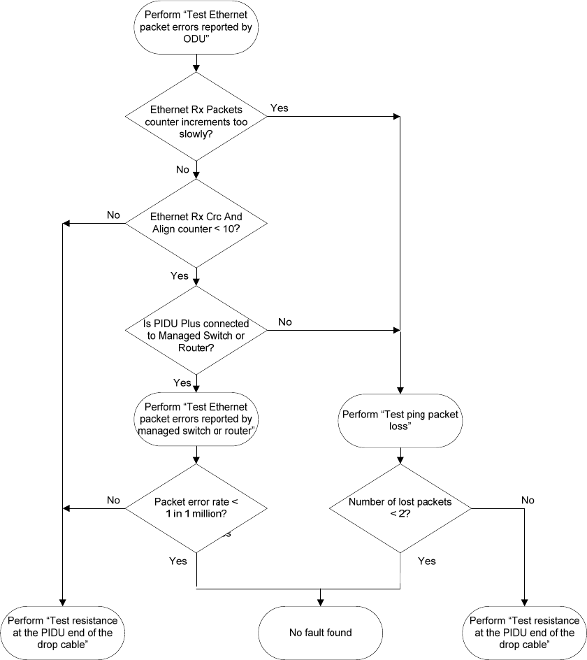
Test link end hardware Chapter 7 Troubleshooting
phn-0896_009v003
7-4 UNDER DEVELOPMENT Feb 2010
Figure 7-2 Link end hardware test flowchart #2

User Guide: PTP 600 Series Test link end hardware
phn-0896_009v003
Feb 2010 UNDER DEVELOPMENT 7-5
Power LED is off
If the Power LED is not on solid or flashing, proceed as follows:
Procedure 7-3 Test the power supply
1 Remove the power lead from the PIDU Plus.
2 Test that the power supply (mains or 56 V battery) is working.
3 If the power supply is not working, investigate the cause.
If the power supply is working, proceed as follows:
Procedure 7-4 Remove ODU cable from PIDU Plus
1 Open the flap on the left hand side of the PIDU Plus.
2 Remove the ODU cable from the PIDU Plus.
3 Observe the effect on the Power LED; does it illuminate?
If the Power LED does not illuminate when the ODU cable is removed, proceed as
follows:
Procedure 7-5 Power LED does not illuminate when ODU cable is removed
1 Measure the voltage across the +55 V and 0 V pads inside the PIDU Plus flap.
If the voltage is incorrect, it indicates that the PIDU Plus is short-circuited.
Report a suspected PIDU Plus fault to Motorola.
2 Measure the impedance across the Power connector.
If the impedance is incorrect, it indicates that the PIDU Plus is short-circuited.
Report a suspected PIDU Plus fault to Motorola.
3 If both of the above tests produce correct readings, it is likely that the PIDU
Plus Power LED is faulty. Report a suspected PIDU Plus fault to Motorola.

Test link end hardware Chapter 7 Troubleshooting
phn-0896_009v003
7-6 UNDER DEVELOPMENT Feb 2010
If the Power LED does illuminate when the ODU cable is removed, proceed as follows:
Procedure 7-6 Power LED does illuminate when ODU cable is removed
1 Remove the jumper (J905) found inside the PIDU Plus flap.
2 Measure the current with an ammeter placed across the two jumper pins. It
should be 10 mA with the ODU disconnected.
If the ammeter reading is incorrect, report a suspected PIDU Plus fault to
Motorola.
If all tests so far have succeeded, proceed as follows:
Procedure 7-7 Other power tests
1 Reconnect the ODU cable to the PIDU Plus.
2 Measure the current with an ammeter placed across the two jumper pins. It
should be in the range 300 mA to 1 A with the ODU connected.
3 If the ammeter reading is too high, the ODU may be drawing too much power,
or the ODU may be short-circuited. Report a suspected ODU fault to Motorola.
4 If the ammeter reading is too low, the PIDU Plus may be supplying too little
power. Report a suspected PIDU Plus fault to Motorola.

User Guide: PTP 600 Series Test link end hardware
phn-0896_009v003
Feb 2010 UNDER DEVELOPMENT 7-7
Power LED is flashing
If the green Power LED is flashing, proceed as follows:
Procedure 7-8 Power LED is flashing
1 Remove and examine the cable that connects the PIDU Plus to the LPU or ODU.
2 Check that pins 4&5 and 7&8 are not crossed with pins 1&2 and 3&6.
3 Check that the resistance between pins 1&8 is greater than 100K ohms.
4 If either check fails, replace or repair the cable that connects the PIDU Plus to
the LPU or ODU.
Ethernet LED did not flash 10 times
When the PIDU Plus is connected to the power supply and the green Power LED
illuminates, there should be a 45 second delay, following which the yellow Ethernet
LED should flash 10 times.
If the Ethernet LED did not flash 10 times, proceed as follows:
Procedure 7-9 Ethernet LED did not flash 10 times
1 Remove and examine the cable that connects the PIDU Plus to the LPU or ODU.
2 Check that the wiring to pins 4&5 and 7&8 is correct. For example, the wiring
to pins 4 and 7 may be crossed.
3 If an LPU is installed, it can be used to check that power is available on the
cable to the ODU. The connections can be accessed by rotating the LPU lid as
shown in Figure 7-3. The Lid nut only needs to be slacken, do not remove. Test
that point P1 on the LPU PCB corresponds to pin 1 on the RJ45. Repeat for
points P2 to P8. An indication of power on the Ethernet cable is also provided
inside the LPU: the LED PWR1 should illuminate but LED PWR2 should not.
4 If either test fails, replace or repair the cable that connects the PIDU Plus to the
LPU or ODU.
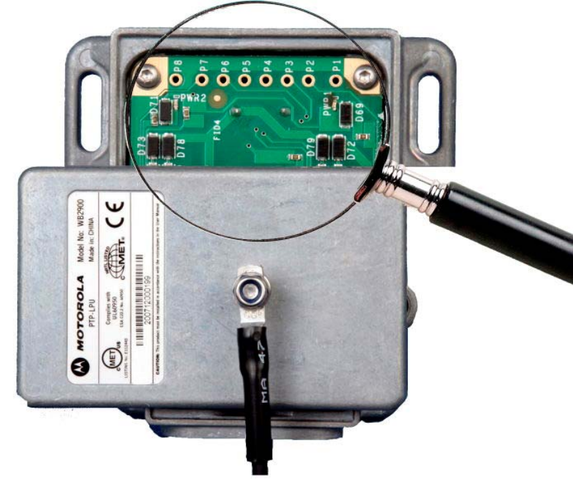
Test link end hardware Chapter 7 Troubleshooting
phn-0896_009v003
7-8 UNDER DEVELOPMENT Feb 2010
Figure 7-3 PTP LPU test points

User Guide: PTP 600 Series Test link end hardware
phn-0896_009v003
Feb 2010 UNDER DEVELOPMENT 7-9
No Ethernet activity
If the Ethernet LED did flash 10 times but then went off, proceed as follows:
Procedure 7-10 Ethernet LED flashed 10 times then went out
1 Check that the RJ45 connection from the LAN port of the PIDU Plus to the PC is
working.
2 If the PC connection is working, remove and examine the cable that connects
the PIDU Plus to the LPU or ODU.
3 Check that the wiring to pins 1&2 and 4&6 is correct. For example, the wiring
to pins 1 and 4 may be crossed.
4 If this test fails, replace or repair the cable that connects the PIDU Plus to the
LPU or ODU.
Irregular Ethernet activity
The yellow Ethernet LED should blink randomly as normal traffic passes through. If
the Ethernet LED flashes irregularly, for example there is a short flash followed by a
long flash, this indicates that the ODU has booted in recovery mode. The causes may
be installation wiring or a corrupt ODU software load. For more information, see Using
recovery mode on page 7-20.
Connection is not 1000 BaseT
If the Ethernet connection to the network is only 10/100 BaseT, when 1000 BaseT is
expected, proceed as follows:
Procedure 7-11 Connection is not 1000 BaseT
1 Remove and examine the cable that connects the PIDU Plus to the LPU or ODU.
2 Check that the wiring to pins 4&5 and 7&8 is correct. For example, the wiring
to pins 4 and 7 may be crossed.
3 If this test fails, replace or repair the cable that connects the PIDU Plus to the
LPU or ODU.

Test link end hardware Chapter 7 Troubleshooting
phn-0896_009v003
7-10 UNDER DEVELOPMENT Feb 2010
Test Ethernet packet errors reported by ODU
To test for Ethernet packet errors, proceed as follows:
Procedure 7-12 Test for Ethernet packet errors
1 Log in to the ODU and select Administration, Statistics, Detailed Counters.
2 Select Reset System Counters at the bottom of the page and wait until
the Ethernet Rx Packets counter has reached 10 million.
NOTE
The count will only update when the page is refreshed.
3 If the counter does not increment or increments too slowly, because for example
the PTP 600 is newly installed and there is no offered Ethernet traffic, then
abandon this procedure and consider using the procedure Test ping packet
loss on page 7-11.
4 Check the Ethernet Rx Crc And Align counter. The test has passed if this is less
than 10.
Test Ethernet packet errors reported by managed switch or
router
If the PTP 600 is connected directly to a managed LAN device, for example an
Ethernet switch or router, it should be possible to carry out a check on the rate of
errored Ethernet packets monitored by the managed device. Please refer to the user
guide of the managed LAN device.
The test has passed if the rate of packet errors reported by the LAN device is less than
1 in 1 million packets.

User Guide: PTP 600 Series Test link end hardware
phn-0896_009v003
Feb 2010 UNDER DEVELOPMENT 7-11
Test ping packet loss
It is possible to generate and monitor for lost packets by using a computer. This can be
achieved using the Command Prompt application which is supplied as standard with
Windows and MAC operating systems.
To test ping packet loss, proceed as follows:
Procedure 7-13 Test ping packet loss
1 Ensure that the IP address of the computer is configured appropriately for
connection to the PTP 600 under test.
2 Ensure that the IP address of the computer does not clash with other devices
connected to the network.
3 If the PIDU Plus is connected to an Ethernet Switch or Router then connect the
computer to a spare port, if available.
4 If it is not possible to connect the computer to a spare port of the networking
equipment, then the PIDU Plus will need to be disconnected from the network
in order to execute this test.
CAUTION
The following steps will disrupt network traffic carried by the PTP 600
under test.
Disconnect the PIDU Plus from the network.
Connect the computer directly to the LAN port of the PIDU Plus.
5 On the computer, open the Command Prompt application.

Test link end hardware Chapter 7 Troubleshooting
phn-0896_009v003
7-12 UNDER DEVELOPMENT Feb 2010
6 Send 1000 ping packets of length 1500 bytes. The process will take 1000
seconds, which is approximately 17 minutes.
If the computer is running a Windows operating system, this is achieved by
typing:
ping –n 900 –l 1500 <ipaddress>
where <ipaddress> is the IP address of the PTP 600 ODU under test.
If the computer is running a MAC operating system, this is achieved by typing:
ping –c 900 –s 1492 <ipaddress>
where <ipaddress> is the IP address of the PTP 600 ODU under test.
7 Record how many Ping packets have been lost. This is reported by Command
Prompt on completion of the test.
The test has passed if the number of lost packets is less than 2.
Test resistance at the PIDU end of the drop cable
If the above procedures fail to diagnose the issue, there may be a fault in the wiring of
the drop cable that connects the ODU (or LPU) to the PIDU Plus. Perform this task to
test the resistances between the RJ45 pins.
Use the PTP drop cable tester (Figure 7-4) to make tesing easier. This can be ordered
from http://www.motorola.com/ptp/support by selecting Order Cable Tester and
completing the order form.
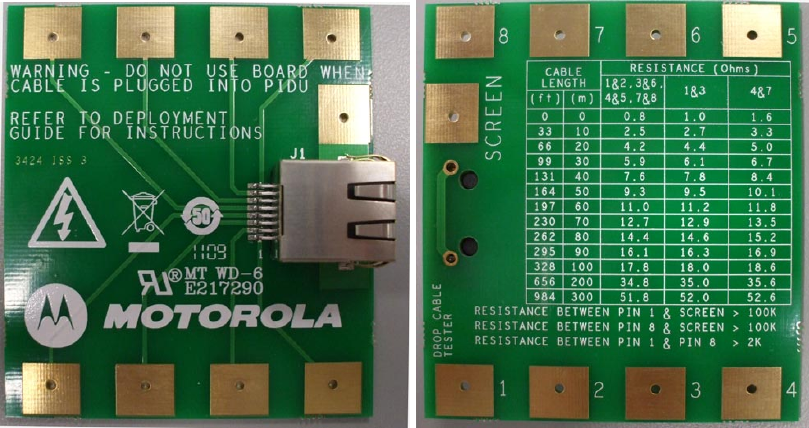
User Guide: PTP 600 Series Test link end hardware
phn-0896_009v003
Feb 2010 UNDER DEVELOPMENT 7-13
Figure 7-4 Drop cable tester (front and back views)

Test link end hardware Chapter 7 Troubleshooting
phn-0896_009v003
7-14 UNDER DEVELOPMENT Feb 2010
To test RJ45 resistance, proceed as follows:
Procedure 7-14 Test RJ45 resistance
1 Unplug the cable that connects the PIDU Plus to the LPU or ODU from the
PIDU Plus.
2 Measure the cable resistances at the RJ45 between the pairs of pins specified
in Table 7-1. The measured resistances should be less than those quoted for
the applicable drop cable length.
3 Measure the resistance between pin 1 and the screen (ODU ground). It should
be greater than 100K ohms for all cable lengths.
4 Measure the resistance between pin 8 and the screen (ODU ground). It should
be greater than 100K ohms for all cable lengths.
5 Measure the resistance between pin 1 and pin 8.
If UltraSync GPS is not fitted, it should be greater than 100K ohms all cable
lengths.
If UltraSync GPS is fitted, it should be greater than 2K ohms all cable lengths.

User Guide: PTP 600 Series Test link end hardware
phn-0896_009v003
Feb 2010 UNDER DEVELOPMENT 7-15
Table 7-1 Expected RJ45 cable resistances at the PIDU Plus
Drop cable
length
(meters)
Between pins 1&2,
3&6 , 4&5 and
7&8 (ohms)
Between
pins 1&3
(ohms)
Between pins 4&7 (ohms)
0 0.8 1.0 1.6
10 2.5 2.7 3.3
20 4.2 4.4 5.0
30 5.9 6.1 6.7
40 7.6 7.8 8.4
50 9.3 9.5 10.1
60 11.0 11.2 11.8
70 12.7 12.9 13.5
80 14.4 14.6 15.2
90 16.1 16.3 16.9
100 17.8 18.0 18.6
200 34.8 35.0 35.6
300 51.8 52.0 52.6
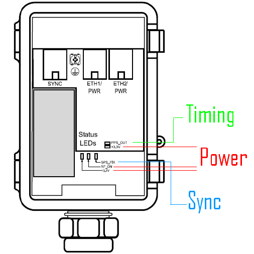
Test link end hardware Chapter 7 Troubleshooting
phn-0896_009v003
7-16 UNDER DEVELOPMENT Feb 2010
Test UltraSync GPS receiver
The UltraSync GPS synchronization unit, if installed, is located between the ODU and
the LPU (Figure 2-17 and Figure 2-18). Use the status LEDs (Figure 7-5) to test the
GPS unit.
Figure 7-5 GPS synchronization unit
To troubleshoot the GPS synchronization unit, perform the following test procedure:
Power supply: Check that the +3.3V and RF_ON LEDs are lit, indicating that the
GPS is receiving power. If they are not lit, confirm that all link end hardware (PIDU
Plus, LPU, ODU and cabling) tests have been performed.
Synchronization: Approximately 2 minutes after powering on, the GPS_FIX LED
should be lit. If it is not, ensure the GPS is at a height of at least 1.8m above the
ground, where there is an unobstructed path to the sky.
Timing: When the GPS_FIX LED lights up, the PPS_OUT LED should begin blinking
faintly at one pulse per second, indicating that sync is being generated. If does not,
replace or repair the GPS synchronization unit.

User Guide: PTP 600 Series Test radio link
phn-0896_009v003
Feb 2010 UNDER DEVELOPMENT 7-17
Test radio link
If the radio link is not working, or it is unreliable, or the data throughput rate is too
low, perform the tests specified in this section. It may be necessary to test the ODUs at
both ends of the link.
No activity
If there is no wireless activity, perform Procedure 7-15.
Procedure 7-15 Testing an inactive radio link
1 Check for Alarm conditions on Home page.
2 Check that the software at each end of the link is the same version.
3 Check that the Target Mac address is correctly configured at each end of the
link.
4 Check Range.
5 Check Tx Power.
6 Check License keys to ensure that both units are the same product variant.
7 Check Master/Slave status for each unit and ensure that one unit is Master
and the other unit is slave.
8 Check that the link is not obstructed or the ODU misaligned.
9 Check the DFS page at each end of the link and establish that there is a quiet
wireless channel to use.
10 If there are no faults found in the configuration and there is absolutely no
wireless signal, retry the installation procedure.
11 If this does not work then report a suspected ODU fault to Motorola.

Test radio link Chapter 7 Troubleshooting
phn-0896_009v003
7-18 UNDER DEVELOPMENT Feb 2010
Some activity
If there is some activity but the link is unreliable or does not achieve the data rates
required, perform Procedure 7-16.
Procedure 7-16 Testing a slow or unreliable radio link
1 Check that the interference has not increased using the i-DFS measurements.
2 If a quieter channel is available check that it is not barred.
3 Check that the path loss is low enough for the communication rates required.
4 Check that the ODU has not become misaligned.

User Guide: PTP 600 Series Lightning strike
phn-0896_009v003
Feb 2010 UNDER DEVELOPMENT 7-19
Lightning strike
If a link end installation is struck by lightning, perform Procedure 7-17.
Procedure 7-17 Testing a link end after lightning strike
1 Perform the tests specified in Test link end hardware on page 7-2.
2 Ensure that the PIDU Plus is working and that the resistances are correct as
specified in Test resistance at the PIDU on page 7-12.
3 If the ODU is not working, power off the ODU and both LPUs and return them
to Motorola.
4 If the ODU is working but there is suspicion of damage to the LPU, then take
the LPUs down and take the covers off, inspect for damage, test the big diode
for short circuit and test all other diodes for forward voltage.

Using recovery mode Chapter 7 Troubleshooting
phn-0896_009v003
7-20 UNDER DEVELOPMENT Feb 2010
Using recovery mode
This section provides instructions to allow users to recover a PTP 600 link.
The Motorola PTP 600 point-to-point wireless Ethernet bridges have a special mode of
operation that allows the user to recover a unit from configuration errors or software
image corruption.
The following topics are described in this section:
• Entering recovery mode on page 7-20
• Upgrade software image on page 7-22
• Reset IP & Ethernet configuration on page 7-23
• Erase configuration on page 7-25
• Reboot on page 7-27
Entering recovery mode
Recovery mode is entered by depressing the Recovery Switch located on the underside
of the PIDU Plus while applying mains power, as shown in PIDU Plus PTP 300/500/600
Series on page 1-9. The Recovery Switch should be held in the depressed state for
between 10 and 20 seconds after the application of mains power. The Ethernet LED
will flash with 10 double flashes at power up (following the release of the Recovery
switch).
When in recovery mode the user will be able to access the unit via the Ethernet
interface. The Ethernet interface will have its IP address set to 169.254.1.1 (or
10.10.10.10). On connection to a unit in recovery mode the following screen is
displayed (Figure 7-6):
Figure 7-6 Recovery Image Warning page
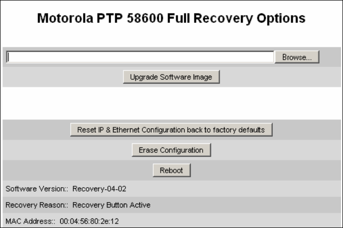
User Guide: PTP 600 Series Using recovery mode
phn-0896_009v003
Feb 2010 UNDER DEVELOPMENT 7-21
Clicking on the warning page image will take the user on to the Recovery Option Page
(Figure 7-7).
Figure 7-7 Recovery Options page
The recovery options available are:
Upgrade Software Image
This allows the user to reload a software image. This may be the original image if
software corruption is suspected or a step back to an old image if an incorrect image
has just been loaded.
Reset IP & Ethernet Configuration back to factory defaults
This allows the user to reset the unit back to the factory defaults:
o IP Address 169.254.1.1 (or 10.10.10.10)
o Netmask 255.255.0.0
o Gateway 169.254.1.0
o Ethernet Interface Auto-negotiate, Auto-MDI/MDIX
Erase Configuration
This allows the user to erase the unit’s entire configuration. Executing this option will
also erase factory settings such as target MAC address, range setting, license key, etc.

Using recovery mode Chapter 7 Troubleshooting
phn-0896_009v003
7-22 UNDER DEVELOPMENT Feb 2010
Reboot
This allows the user to reboot the unit. This option must be executed after resetting
the IP & Ethernet configuration or erasing the configuration detailed above.
Software Version
This is the software version of the recovery operating system permanently installed
during manufacture.
Recovery Reason
Indicates the reason the unit is operating in Recovery mode. Possible reasons are
“Recovery button active” or “Invalid or corrupt image”
MAC Address
The MAC address shown here is the MAC address of the unit programmed during
manufacture.
Upgrade software image
The first step (Figure 7-7) is to use the ‘Browse’ button to locate the software image to
be downloaded. Once located the user should press the “Upgrade Software Image”
button to start the software download process.
During software download, progress is indicated by a pair of progress bars (Figure
7-8).
Figure 7-8 Upgrade Progress Tracker page
When the download is complete a page is displayed indicating the status of the
software download (Figure 7-9).
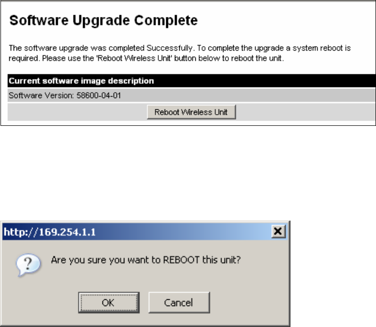
User Guide: PTP 600 Series Using recovery mode
phn-0896_009v003
Feb 2010 UNDER DEVELOPMENT 7-23
Figure 7-9 Software Upgrade Complete page
After carefully checking that correct image has been downloaded the user should
reboot the unit by pressing the “Reboot Wireless Unit” button. The user will then be
presented with a pop up box asking them to confirm the action (Figure 7-10).
Figure 7-10 Reboot confirmation pop up
The unit will now reboot. Providing the unit configuration is still intact the unit should
restart in normal operational mode and the link should recover. If the unit or link fails
to recover, refer to Test link end hardware on page 7-2.
Reset IP & Ethernet configuration
To reset IP & Ethernet configuration back to factory defaults the user should press the
“Reset IP & Ethernet Configuration back to factory defaults” button on the “Recovery
Options” page (2Figure 7-7). The user will now be presented with a pop up box asking
them to confirm the action (Figure 7-11).
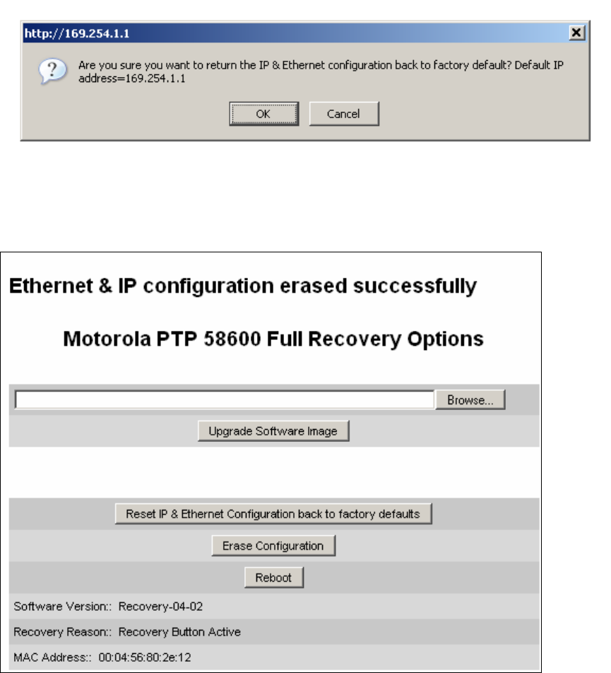
Using recovery mode Chapter 7 Troubleshooting
phn-0896_009v003
7-24 UNDER DEVELOPMENT Feb 2010
Figure 7-11 Confirm reset to factory default pop up
On confirmation the following page will be displayed (Figure 7-12). The user should
now reboot the unit by pressing the “Reboot” button.
Figure 7-12 Ethernet & IP configuration erased successfully page
The user will now be presented with a pop up box asking them to confirm the action
(Figure 7-13).
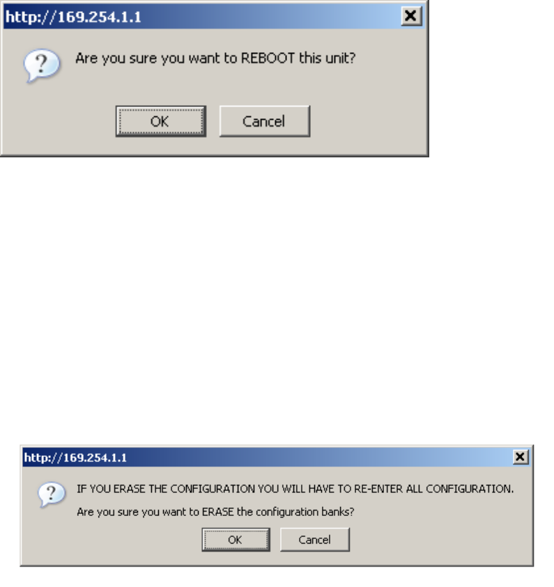
User Guide: PTP 600 Series Using recovery mode
phn-0896_009v003
Feb 2010 UNDER DEVELOPMENT 7-25
Figure 7-13 Reboot confirmation pop up
The unit will now reboot. The unit should now start up in normal mode but with the IP
address set to 169.254.1.1 and the Ethernet interface set to auto-negotiate and auto-
MDI/MDIX. If the unit fails to recover, refer to Test link end hardware on page 7-2.
Erase configuration
To erase the unit’s configuration the user should press the “Erase Configuration”
button on the “Recovery Options” page (Figure 7-7). The user will now be presented
with a pop up box asking them to confirm the action (Figure 7-14).
Figure 7-14 Confirm erase configuration pop up
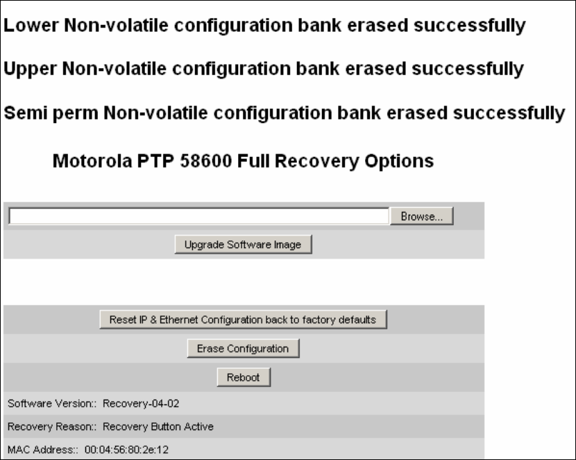
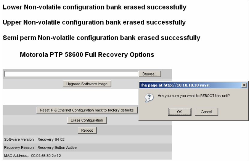
User Guide: PTP 600 Series Using recovery mode
phn-0896_009v003
Feb 2010 UNDER DEVELOPMENT 7-27
The user will now be presented with a pop up box asking them to confirm the action
(Figure 7-16)
Figure 7-16 Erase configuration - reboot confirmation pop up
The unit will now reboot. The unit should now start up in normal mode but with all
configuration erased. If the unit fails to start up, refer to Test link end hardware on
page 7-2.
Reboot
This option can be used to reboot the unit. The user will now be presented with a pop
up box asking them to confirm the action (Figure 7-17).
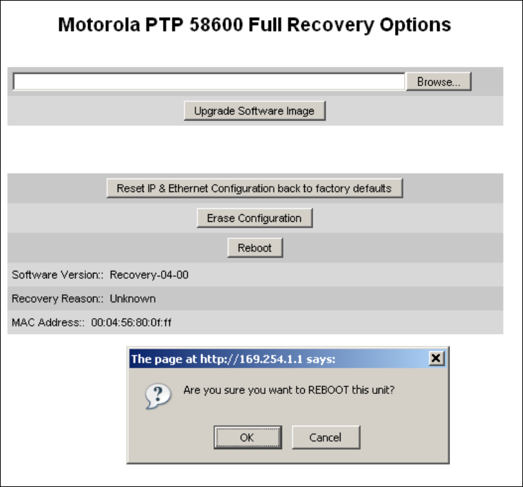
Using recovery mode Chapter 7 Troubleshooting
phn-0896_009v003
7-28 UNDER DEVELOPMENT Feb 2010
Figure 7-17 Recovery - reboot confirmation pop up
The unit will now reboot. The unit should now start up in normal operational mode. If
the unit fails to start up, refer to Test link end hardware on page 7-2.

Chapter 8
phn-0896_009v003
Feb 2010 UNDER DEVELOPMENT 8-1
Chapter 8 Connectorized PTP 600 series
. . . . . . . . . . . . . . . . . . . . . . . . . . . . . . . . . . . . . . . . . . . . . . . . . . . . . . . . . . . .
.
.
.
.
This section details the changes and additional features relevant to the connectorized
version of the PTP 600 Series products.
The following topics are described in this section:
• Product description on page 8-2.
• Software and features on page 8-3.
• Deployment considerations on page 8-9.
• Regulatory issues with connectorized units on page 8-10.
• Antenna choices on page 8-13.
• Installing connectorized bridges on page 8-14.
• Additional lightning protection on page 8-20.
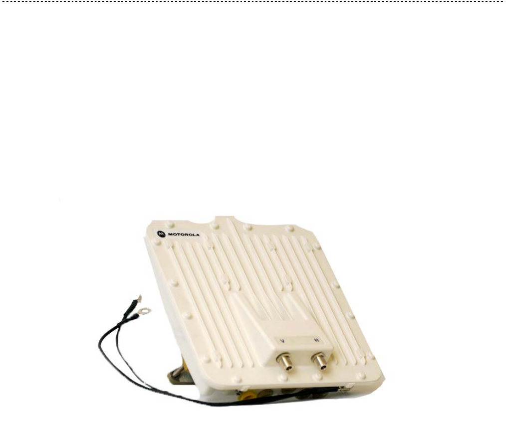
Product description Chapter 8 Connectorized PTP 600 series
phn-0896_009v003
8-2 UNDER DEVELOPMENT Feb 2010
Product description
Hardware
The Connectorized PTP 600 Series is a variant designed to provide the system
integrator and installer with the ability to provide extra capability to cope with very
difficult radio links compared to the PTP 600 Series Integrated model. The variant
allows the use of a variety of externally mounted antennas, either Flat Plate or Dish,
which have higher gains than provided by the integrated antenna that is normally
used.
Figure 8-1 Connectorized PTP 600 Series outdoor unit
Antenna
The antenna choices for the Connectorized PTP 58600 and 54600 are described in
Antenna choices on page 8-13.
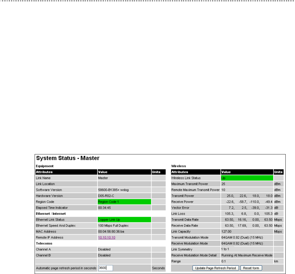
User Guide: PTP 600 Series Software and features
phn-0896_009v003
Feb 2010 UNDER DEVELOPMENT 8-3
Software and features
This section only describes the areas where functionality is modified for the
connectorized variant. For details of the functionality that is common to the integrated
and connectorized variants, see Chapter 6 Operation.
Status page
The link loss calculation presented on the Status Page of the management interface
has to be modified to allow for the increased antenna gains at each end of the link.
The manufacturing process of the Connectorized 600 Series configures the standard
hardware of the unit for use with external antennas. The installer is prompted, as part
of the installation process, to enter the gain of the external antenna(s) and cable losses
at each end of the link. Peer-to-peer messaging is used to pass the effective antenna
gain to each end of the link so that the link loss calculations can be correctly
computed.
Figure 8-2 Connectorized PTP 600 Series Status page
Configuration pages
The Configuration web page for the connectorized variant is shown in Figure 8-3. The
parameters Antenna Gain, Cable Loss and EIRP are specific to the connectorized
variant.
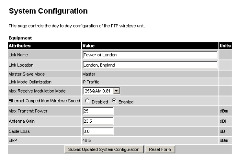
Software and features Chapter 8 Connectorized PTP 600 series
phn-0896_009v003
8-4 UNDER DEVELOPMENT Feb 2010
Figure 8-3 Connectorized PTP 600 Series System Configuration page
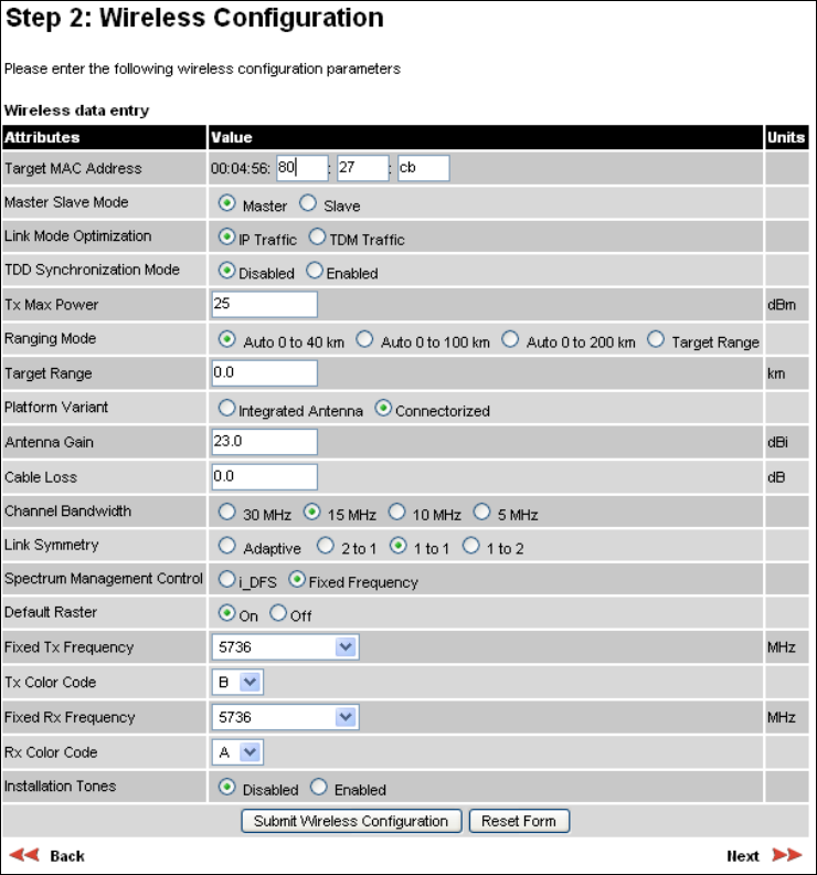
User Guide: PTP 600 Series Software and features
phn-0896_009v003
Feb 2010 UNDER DEVELOPMENT 8-5
Installation pages
The installer is prompted to enter the Antenna Gain and Cable Loss (Connectorized
PTP 600 Series to antenna) at each end of the link. The Installation Pages for the
connectorized version are shown as Figure 8-4 to Figure 8-6.
Figure 8-4 Connectorized PTP 600 Series Wireless Configuration page

Software and features Chapter 8 Connectorized PTP 600 series
phn-0896_009v003
8-6 UNDER DEVELOPMENT Feb 2010
The following fields are relevant to connectorized ODUs:
Antenna Gain
Gain of the antenna you are connecting to the unit, see Antenna choices on page 8-13.
Cable Loss
Loss in the cable between the ODU and the antenna.
NOTE
If there is a significant difference in length of the antenna cables for the two
antenna ports, then the average value should be entered.
Spectrum Management Control
Is used to configure the PTP 600 Series Spectrum Management features, see
Spectrum management on page 6-22 for more details. i-DFS is the abbreviation for
intelligent Dynamic Frequency Selection, which continually monitors the spectrum
looking for the channel with the lowest level of on channel and co-channel
interference. Fixed frequency mode allows the installer to fix the Transmit and receive
frequencies on the units. The frequencies may be configured symmetrically or
asymmetrically.
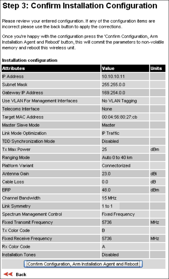
User Guide: PTP 600 Series Software and features
phn-0896_009v003
Feb 2010 UNDER DEVELOPMENT 8-7
Figure 8-5 Connectorized PTP 600 Series Confirm Installation page
EIRP
The Confirm Installation Page displays the EIRP (Effective Isotropic Radiated Power),
which describes the strength of the radio signal leaving the wireless unit. This allows
the operator to verify that their link configuration (Max Transmit Power, Antenna Gain
and Cable Loss) do not cause the link to exceed any applicable regulatory limit.
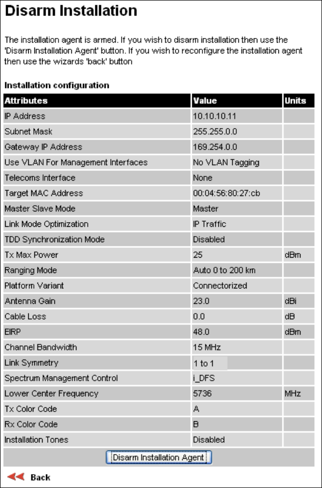
Software and features Chapter 8 Connectorized PTP 600 series
phn-0896_009v003
8-8 UNDER DEVELOPMENT Feb 2010
Figure 8-6 Connectorized PTP 600 Series Disarm Installation page

User Guide: PTP 600 Series Deployment considerations
phn-0896_009v003
Feb 2010 UNDER DEVELOPMENT 8-9
Deployment considerations
When to use external antennas
The majority of radio links can be successfully deployed with the PTP 600 Series. It
should only be necessary to use external antennas where the LINKPlanner indicates
marginal performance for a specific link – for example when the link is heavily
obscured by dense woodland on an NLOS link or extremely long LOS links (>80km or
>50 miles) over water.
The external antennas can be either dual-polarization (as the integrated antenna) or
two single polarized antennas can be used in a spatially diverse configuration. It is
expected that the dual-polarization antennas would normally be used to simplify the
installation process; spatially diverse antennas may provide additional fade margin on
very long LOS links where there is evidence of correlation of the fading characteristics
on Vertical and Horizontal polarizations.
Link budget
An estimate of the link budget for a specific application can be obtained by using the
Motorola LINKPlanner tool. For more information see the Motorola web site.

Regulatory issues with connectorized units Chapter 8 Connectorized PTP 600 series
phn-0896_009v003
8-10 UNDER DEVELOPMENT Feb 2010
Regulatory issues with connectorized units
Maximum EIRP
Normal EIRP limits
In most regions (including USA, Canada, Europe and Australia) operation of products
in the band 5470 MHz to 5725 MHz is constrained by an EIRP limit. The constraint is
that the EIRP must not exceed (17 + 10 x Log Bandwidth) dBm.
In some regions (including Europe) operation of products in the band 5725 MHz to
5850/5875 MHz is constrained by an EIRP limit. The constraint is that the EIRP must
not exceed (23 + 10 x Log Bandwidth) dBm.
As the PTP 600 has an operating bandwidth from approximately 5 MHz to
approximately 30 MHz, then the maximum allowed EIRP depends on the operating
bandwidth of the radio as shown in Table 8-1.
Table 8-1 Normal EIRP limits with operating channel bandwidth
Operating bandwidth
(MHz)
Allowed EIRP (dBm) at
5.4 GHz
Allowed EIRP (dBm) at
5.8 GHz
5 24 30
10 27 33
15 28.8 34.8
30 30 36
Calculating EIRP
When operating with external antennas, the installer or operator has to set the
maximum transmit power to ensure that the EIRP limit is not exceeded. The EIRP may
be calculated from:
Allowed EIRP(dBm) = Max_Transmit_Power (dBm) + Antenna Gain (dBi) –
Feeder Losses (dB)
and hence:
Max_Transmit_Power (dBm) = Allowed EIRP(dBm) – Antenna Gain (dBi) +
Feeder Losses (dB)

User Guide: PTP 600 Series Regulatory issues with connectorized units
phn-0896_009v003
Feb 2010 UNDER DEVELOPMENT 8-11
The Set_Max_Transmit_Power parameter
As the actual maximum transmit power can only be adjusted in 1 dB steps, then the
installer or operator must configure the PTP 600 to have a Set_Max_Transmit_Power
parameter as calculated below:
Set_Max_Transmit_Power = [Max_Transmit_Power] rounded down to nearest
lower dB step
In order to simplify matters, the settings to be used for regions with the EIRP limits in
Table 8-1 (assuming short feeder cables) are shown in Table 8-2.
NOTE
Table 8-2 has been calculated on the basis of 0.5 dB cable loss and the
highest gain antennas per size of which we are aware. At these operating
frequencies, feeder losses even with short cables are unlikely ever to be
below 0.5 dB for practical installations and cable diameters.
Table 8-2 Setting maximum transmit power to meet general EIRP limits
Set_Max_Transmit_Power parameter
setting (dBm)
Antenna
size
Maximum
available
antenna
gain
(dBi)
Operating
bandwidth (MHz)
5.4 GHz 5.8 GHz
5 -6 0
10 -3 3
15 -2 4
2ft dish 29.4
30 1 7
5 Not allowed -2
10 -5 1
15 -3 3
2.5ft dish 31.2
30 0 6
5 Not allowed -4
10 -7 -1
15 -5 0
3ft dish 33.4
30 -2 3

Regulatory issues with connectorized units Chapter 8 Connectorized PTP 600 series
phn-0896_009v003
8-12 UNDER DEVELOPMENT Feb 2010
Set_Max_Transmit_Power parameter
setting (dBm)
Antenna
size
Maximum
available
antenna
gain
(dBi)
Operating
bandwidth (MHz)
5.4 GHz 5.8 GHz
5 Not allowed -6
10 Not allowed -3
15 -7 -1
4ft dish 34.8
30 -4 2
Cable losses (FCC regions only)
The FCC approval for the product is based on tests with a cable loss between the units
of not less than 1.2 dB at 5.8 GHz. The use of lower cable losses would result in the
installation being outside the FCC rules. As an indication, 1.2 dB of cable loss
corresponds to the following cable lengths excluding connector losses (source: Times
Microwave).
Table 8-3 Cable losses per length
Length for 1.2dB Cable Loss at 5.8 GHz
Cable
(ft) (m)
LMR100 1.9 0.6
LMR200 4.6 1.4
LMR300 7.25 2.2
LMR400 11.1 3.4
LMR600 16.5 5.0

User Guide: PTP 600 Series Antenna choices
phn-0896_009v003
Feb 2010 UNDER DEVELOPMENT 8-13
Antenna choices
Antenna selection criteria
The main selection criterion is the required antenna gain. The secondary criterion is
the ease of mounting and alignment. For example, the Radio Waves Parabolic dishes
are supplied with a mount that allows adjustment for alignment independent of the
actual antenna mounting. This type of antenna is much easier to align than those that
have to be rotated around the mounting pole for alignment.
Non-FCC regions
In non-FCC regions, antenna choice is not restricted, but any region specific EIRP limit
must be obeyed by reducing the maximum Transmit power, see Licenses and region
codes on page 2-3.
FCC regions
In FCC regions, antenna choice is restricted as described in PTP 54600 FCC antenna
restrictions on page 4-64 and PTP 58600 FCC antenna restrictions on page 4-85.
The maximum permitted antenna gain depends upon product variant and channel
bandwidth, as specified in PTP 49600 radio system specifications on page 4-47 and
Regulatory issues with connectorized units on page 8-10.

Installing connectorized bridges Chapter 8 Connectorized PTP 600 series
phn-0896_009v003
8-14 UNDER DEVELOPMENT Feb 2010
Installing connectorized bridges
The section covers the generic installation instructions for the Connectorized versions
of the PTP 600 Series point-to-point wireless Ethernet bridges. The actual installation
procedure will depend on antenna choice, cable choice, required antenna separation
etc.
PTP 54600 FCC antenna restrictions on page 4-64 and PTP 58600 FCC antenna
restrictions on page 4-85 show a wide variety of antennas that can be used with the
Connectorized PTP 600 Series.
Cables and connectors
Cables should be selected using the above criteria. However it should be noted that a
cable of a type similar to LMR400 is a lot more difficult to handle and route than a
cable of a type similar to LMR100.
Motorola recommends the use of weatherproof connectors, preferably ones that come
supplied with adhesive lined heat shrink sleeve that is fitted over the cable/connector
interface.
The connectors required at the Connectorized PTP 600 Series end of the antenna
cables are N-Type Male.
The connectors required at the antenna end of the antenna cables is dependant on the
antenna type chosen.
Tools
The tools required for mounting a Connectorized PTP 600 Series unit are the same as
those required for an Integrated 600 Series detailed in Preparing for site installation
on page 5-7. The tools required for mounting the antennas are specific to the antenna
chosen. The installer should refer to the antenna manufacturer’s instructions.
User Guide: PTP 600 Series Installing connectorized bridges
phn-0896_009v003
Feb 2010 UNDER DEVELOPMENT 8-15
Miscellaneous supplies
The following miscellaneous supplies will be required:
• Cable ties, cable cleats – for securing cables
• Self-amalgamating tape – to weatherproof the RF connectors
• PVC tape – for additional protection of the RF connectors and securing cables
Mounting the connectorized PTP 600
A Connectorized PTP 600 Series is shipped with the same bracket as supplied with an
Integrated unit. Details on the use of this bracket can be found in Mounting brackets
on page 1-7. The PTP 600 Series should be mounted in a position that gives it
maximum protection from the elements, but still allows easy access for making off the
various connections and applying the recommended weatherproofing.
When using dual polar antennas the Connectorized PTP 600 Series should be mounted
in such a position as to minimize the cable length, keeping losses to a minimum, taking
into account the minimum cable lengths required by the FCC regulations, see PTP
58600 FCC antenna restrictions on page 4-85.
When using separate antennas the Connectorized PTP 600 Series should be mounted
in such a position as to minimize both cable runs between the unit and the antennas. It
is not necessary to mount the Connectorized PTP 600 Series at the mid point between
the antennas.
Mounting the antennas
The Antennas should be mounted according to the manufacturer’s instructions. Actual
antenna position will depend on the available mounting positions and link
requirements. It may be necessary to mount the antennas 20m apart or at a certain
distance from the ground to get the desired results.

Installing connectorized bridges Chapter 8 Connectorized PTP 600 series
phn-0896_009v003
8-16 UNDER DEVELOPMENT Feb 2010
Alignment process
When aligning antennas deployed with a Connectorized PTP 600 Series unit it may not
be possible to hear the alignment tone emanating from the unit. In this case it may be
necessary for a second installer to assist in the operation. Alternatively, it may be
possible to extend the tube on the supplied stethoscope to give a longer reach.
NOTE
Fine antenna alignment can sometimes be achieved by tightening and loosening
the bolts on either side of the antenna mounting bracket, rather than trying to
turn the whole bracket on the mounting pole.
Aligning dual polar antennas
The process for aligning a dual polar antenna is the same as aligning an Integrated
unit with an integrated antenna. This procedure is detailed in Using the ODU
installation tones on page 5-59.

User Guide: PTP 600 Series Installing connectorized bridges
phn-0896_009v003
Feb 2010 UNDER DEVELOPMENT 8-17
Aligning separate antennas
When using separate antennas to achieve spatial diversity, one should be mounted
with Horizontal polarization and the other with Vertical polarization. Follow Procedure
8-1
Procedure 8-1 Aligning separate antennas
1 Mount the Antennas.
2 Mount the connectorized version of the PTP 600 ODU.
3 Route and make off the ends of the Antenna cables.
4 Connect the antenna cables at the antennas.
5 Connect one of the antenna cables at the Connectorized version of the PTP 600
Series unit.
6 Connect the Connectorized PTP 600 Series ODU to PIDU Plus cable and
configure the unit as described in Connecting the ODU, PIDU and LPUs on
page 5-43.
7 Align the connected antenna using the tones as described in Using the ODU
installation tones on page 5-59.
8 Connect the other antenna to the ODU.
9 Disconnect the cable to the already aligned antenna.
10 Align the second antenna using the tones as described in Using the ODU
installation tones on page 5-59.
11 Re-connect the second antenna to the Connectorized PTP 600 Series. The tone
pitch should increase due to the additional received signal.
12 Use the relevant status web pages to check that the planned link performance is
achieved.

Installing connectorized bridges Chapter 8 Connectorized PTP 600 series
phn-0896_009v003
8-18 UNDER DEVELOPMENT Feb 2010
Completing the installation
The installation should be completed by checking all mounting nuts bolts and screws,
securing all cables and weatherproofing the installation.
CAUTION
Finally tightening the antenna mountings may cause the antenna alignment
to be altered, due to distortion in the mounting bracket caused by action of
tightening. It is recommended that the installation tone be left turned on
(armed) during this process so that any movement can be noticed and
counteracted by tightening the other side of the bracket.
Antenna cable fixing
Cables should be secured in place using cable ties, cleats or PVC tape. Care should be
taken to ensure that no undue strain is placed on the connectors on both the
Connectorized PTP 600 Series and the Antennas and also to ensure that the cables do
not flap in the wind. Flapping cables are prone to damage and induce unwanted
vibrations in the mast to which the units are attached.
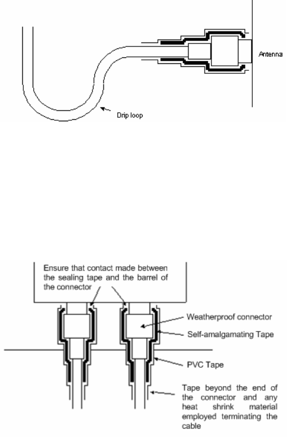
User Guide: PTP 600 Series Installing connectorized bridges
phn-0896_009v003
Feb 2010 UNDER DEVELOPMENT 8-19
Antenna connection weatherproofing
Where a cable connects to an antenna or unit from above, a drip loop should be left to
ensure that water is not constantly channeled towards the connector.
Figure 8-7 Forming a drip loop
All joints should be weatherproofed using self-amalgamating tape. It is recommended
that a layer of PVC tape be placed over the self-amalgamating tape to protect the joint
while the self-amalgamating tape cures and gives additional protection. Figure 8-8
shows this diagrammatically for the PTP 600 Series end of the antenna cables. If the
antenna manufacturer has not supplied guidance on this matter, the same technique
should be employed at the antenna end of the cable.
Figure 8-8 Weatherproofing the antenna connections
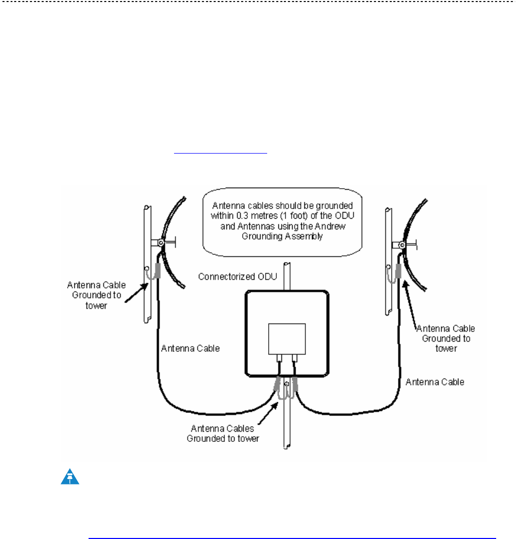
Additional lightning protection Chapter 8 Connectorized PTP 600 series
phn-0896_009v003
8-20 UNDER DEVELOPMENT Feb 2010
Additional lightning protection
The following guidelines should be applied in addition to those described in Lightning
protection on page 2-18.
ODU mounted outdoors
Where the ODU is mounted outdoors and is mounted some distance from the antenna,
it is advisable to add additional grounding by utilizing Andrew Assemblies (such as
Andrew Type 223158 www.andrew.com) as shown in Figure 8-9.
Figure 8-9 Additional grounding when using connectorized units
NOTE
Refer to instructions contained in the Andrew grounding kit for correct
installation, or if instructions are missing, refer to:
http://awapps.commscope.com/catalog/product_details.aspx?id=15832&tab=2
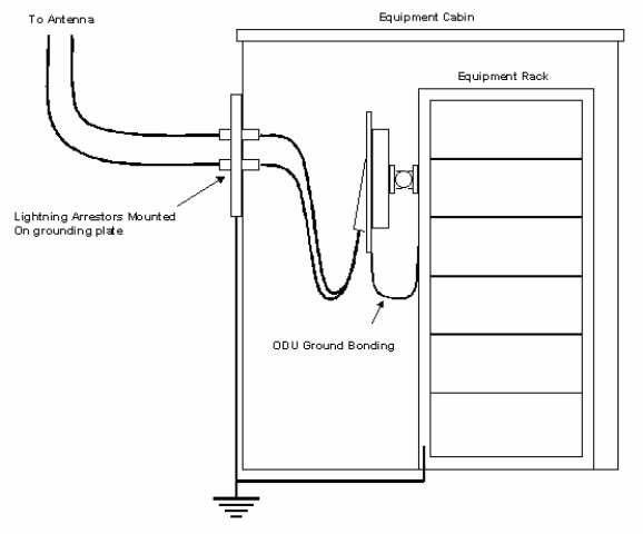
User Guide: PTP 600 Series Additional lightning protection
phn-0896_009v003
Feb 2010 UNDER DEVELOPMENT 8-21
ODU mounted indoors
Where the ODU is mounted indoors, lightning arrestors should be deployed where the
antenna cables enter the building as shown in Figure 8-10.
Figure 8-10 Lightning arrestor mounting
The lighting arrestors should be ground bonded to the building ground at the point of
entry. Motorola recommends Polyphaser LSXL-ME or LSXL lighting arrestors. These should
be assembled as show in Figure 8-11.
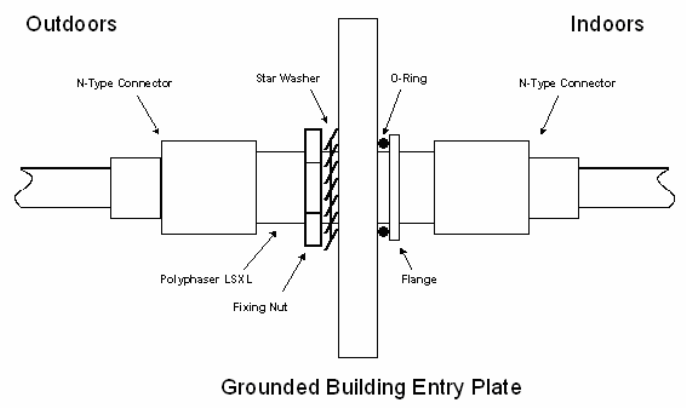
Additional lightning protection Chapter 8 Connectorized PTP 600 series
phn-0896_009v003
8-22 UNDER DEVELOPMENT Feb 2010
Figure 8-11 Polyphaser assembly

Chapter 9
phn-0896_009v003
Feb 2010 UNDER DEVELOPMENT 9-1
Chapter 9 FAQs
. . . . . . . . . . . . . . . . . . . . . . . . . . . . . . . . . . . . . . . . . . . . . . . . . . . . . . . . . . . .
.
.
.
.
This chapter contains answers to frequently asked questions (FAQs) about the PTP
600.

General FAQs Chapter 9 FAQs
phn-0896_009v003
9-2 UNDER DEVELOPMENT Feb 2010
General FAQs
Can I source and use my own PoE adaptor with the PTP 600 Series? No. The
PTP 600 Series uses a non-standard PoE configuration. Failure to use the Motorola
supplied Power Indoor Unit could result in equipment damage and will invalidate the
safety certification and may cause a safety hazard.
Why has Motorola launched the PTP 600 Series? The PTP 600 Series is the first
product to feature Multiple-Input Multiple-Output (MIMO). The PTP 600 Series
solutions allow wireless connections of up to 200km (124 miles) in near line-of-sight
conditions and up to 10km (6 miles) in deep non-line-of-sight conditions.
What is Multiple-Input Multiple-Output (MIMO)? The PTP 600 Series radiates
multiple beams from the antenna - the effect of which is to significantly protect against
fading and to radically increase the probability that the receiver will decode a usable
signal. When the effects of MIMO are combined with those of OFDM techniques and a
best in class link budget, there is a significant improvement to the probability of a
robust connection over a non-line-of-sight path.
What do you mean by “non-line-of-sight”? A wireless connection between two
points without optical line-of-sight, that is, with obstructions between the antennas the
transmitted signal is still able to reach the receiver and produce a good quality link.
What else is special about the PTP 600 Series ? There are many special features
built-in to the hardware of the PTP 600 Series. The product offers the highest system
gain in its class through high sensitivity antennas for improved signal recovery. It also
features a radio system that operates on ultra fast digital signal processors but is
controlled by firmware giving the ability to download new firmware when
enhancements become available. The PTP 600 Series has a built-in web server for
advanced management capabilities including detailed radio signal diagnosis.
In which frequency bands does the PTP 600 Series operate? The Motorola point-
to-point 600 Series operates in the licensed bands 2.5 GHz, 4.5 GHz, 4.8 GHz and 4.9
GHz, and in the unlicensed bands 5.4 GHz (ETSI Band B), 5.8 GHz (ETSI Band C and
FCC ISM band) and 5.9 GHz. Users must ensure that the PTP 600 Series complies with
local operating regulations.
Why does the PTP 600 Series operate in the 5GHz band? The 5 GHz band offers
the dual benefits of high data throughput and good radio propagation characteristics.
The wide band of spectrum available is subdivided into several channels such that
multiple systems can operate in the vicinity without causing interference to one
another.
User Guide: PTP 600 Series General FAQs
phn-0896_009v003
Feb 2010 UNDER DEVELOPMENT 9-3
Is the PTP 600 Series an 802.11a device? No, although similar, the PTP 600 Series
uses different encoding and radio transmission systems from 802.11a. In areas where
802.11a systems are operating, the PTP 600 Series will detect the 802.11a radio
signals and choose a clear channel away from any interference.
How much power does the PTP 600 Series transmit? At all times the PTP 600
Series operates within country / region specific regulations for radio power emissions.
In addition, the PTP 600 Series uses a technique known as Transmit Power Control
(TPC) to ensure that it only transmits sufficient radio power such that the other
antenna can receive a high quality signal.
How does the PTP 600 Series avoid interference from other devices nearby? At
initialization, the PTP 600 Series monitors the available frequency channels to find a
channel that is clear of interference. In operation 600 Series continuously monitors the
spectrum to ensure it is operating on the cleanest channel.
How does the PTP 600 Series integrate into my data network? The PTP 600
Series acts as a transparent bridge between two segments of your network. In this
sense, it can be treated like a virtual wired connection between the two buildings. The
PTP 600 Series forwards 802.3 Ethernet packets destined for the other part of the
network and filters packets it does not need to forward. The system is transparent to
higher-level management systems such as VLANs and Spanning Tree.
How does the PTP 600 Series provide security for data traffic? The PTP 600
Series has a range of security features. At installation time each link must be
programmed with the serial ID of its partner. The two ends of the link will only
communicate with one another, eliminating any chance of "man in the middle" attacks.
Over the air security is achieved through a proprietary scrambling mechanism that
cannot be disabled, spoofed or snooped by commercial tools.
Can I use Apple Macintosh OS X to control and monitor my 600 Series? Yes, but
there are some restrictions. Mozilla 1.6 or higher is recommended.

Link encryption FAQs Chapter 9 FAQs
phn-0896_009v003
9-4 UNDER DEVELOPMENT Feb 2010
Link encryption FAQs
Encryption data entry fields are not available
Check that the correct license key has been inserted into the unit. The current license
key is displayed on the ‘License Key’ data entry page.
Link fails to bridge packets after enabling link encryption
If the wireless link status on the status web page indicates that the link is ‘Searching’,
and you can browse to the local end of the link but not to the remote end, then check
that the same encryption algorithm and key have been entered at both ends of the link.
Failure to enter the same algorithm and key will result in received packets not being
decrypted correctly.
Loss of AES following downgrade
When downgrading (using Recovery software image 05-01 onwards) to an earlier
version of software that does not support AES, the unit will indicate that the region
code is invalid. The user will be required to re-install correct software (supplied when
AES key was activated) and reboot the unit.

Glossary
phn-0896_009v003
Feb 2010 UNDER DEVELOPMENT I
Glossary
. . . . . . . . . . . . . . . . . . . . . . . . . . . . . . . . . . . . . . . . . . . . . . . . . . . . . . . . . . . .
.
.
.
.
Term Definition
ARP Address Resolution Protocol
BPSK Binary Phase Shift Keying
CSP Critical Security Parameter
DC Direct Current
DER Distinguished Encoding Rules
DFS Dynamic Frequency Selection
EIRP Equivalent Isotropic Radiated Power
ETSI European Telecommunications Standards Institute
FAQ Frequently Asked Question
FIPS Federal Information Processing Standard
GPS Global Positioning System
HTTP Hypertext Transfer Protocol
ID Identity
IEEE Institute of Electrical and Electronic Engineers
IP Internet Protocol
IQ In phase / Quadrature
ISM Industrial Scientific and Medical
ITU International Telecommunications Union
LAN Local Area Network
LOS Line-of-Sight (clear line-of-sight, and Fresnel zone is clear)
LPU Lightning Protection Unit
MAC Medium Access Control Layer

Link encryption FAQs Chapter 9 FAQs
phn-0896_009v003
II UNDER DEVELOPMENT Feb 2010
Term Definition
MDI Medium Dependent Interface
MDIX Medium Dependent Interface Crossover
NLOS Non-Line-of-Sight
ODU Outdoor Unit
OFDM Orthogonal Frequency Division Multiplex
PC IBM Compatible Personal Compute
PIDU Plus Power Indoor Unit Plus
PING Packet Internet Groper
PTP Point-to-Point
QAM Quadrature Amplitude Modulation
RAM Random Access Memory
RF Radio Frequency
RSSI Received Signal Strength Indication
SMTP Simple Mail Transport Protocol
SNMP Simple Network Management Protocol
SNTP Simple Network Time Protocol
STP Shielded Twisted Pair
STP Spanning Tree Protocol
TCP Transmission Control Protocol
TLS Transport Layer Security
TPC Transmit Power Control
URL Universal Resource Location
USA United States of America
UTP Unshielded Twisted Pair
UV Ultraviolet
VLAN Virtual Local Area Network

Index
phn-0896_009v003
Feb 2010 UNDER DEVELOPMENT III
Index
. . . . . . . . . . . . . . . . . . . . . . . . . . . . . . . . . . . . . . . . . . . . . . . . . . . . . . . . . . . .
.
.
.
.
1
1000 BaseT
not achieved, 7-9
A
Access key, 6-79
Adaptive modulation
description, 1-22
Adaptive Modulation, 2-10
AES encryption
enabling, 6-96
license, 1-48
Alarm, 6-7, 6-8
Alarms, 6-6
diagnostic, 6-114
supported, 1-41
system alarms, 6-7
Alignment, 5-59, 8-16
Antenna, 8-2, 8-6, 8-13, 8-16, 8-17
Antenna Restrictions
PTP 54600, 4-64
PTP 58600, 4-85
B
Balun, 5-56
Band Edge Power Reduction, 4-82
Bandwidth, 2-5
Brackets, 1-7
C
Cable
Preparation, 5-8
Routing, 5-45
Cable glands
connecting to ODU or LPU, 5-16
disconnecting, 5-18
Cable Loss, 8-6
Connectorized Variant, 8-12
Cables, 1-15, 5-8, 5-39, 5-40, 8-14
for Antennas, 8-18
Capability summary, 6-77
channel bandwidth
and OFDM, 1-22
Channel Bandwidth, 2-5
channels, 6-34
Channels, 6-22
Barring, 6-28
History, 6-30
Clock, 6-118
Compliance, 4-2, 4-7, 4-9
Conditions of Use, 3-3
Configuration, 1-38, 6-48, 7-21
confirmation of, 6-69
Connectorized Variant, 8-3
erasing, 7-25
Ethernet, 6-48
interface, 6-55
manual, 6-52
saving and restoring, 6-81
Spectrum Management, 6-27
Telecoms, 6-49
web pages, 6-19
wireless, 6-59
Connecting, 8-19
at ODU, 5-43, 5-44
at PIDU, 5-46
PIDU to ODU, 5-43
to network, 5-3, 5-59
Index
phn-0896_009v003
IV UNDER DEVELOPMENT Feb 2010
Connections
cables, 5-8
Connectorized Variant, 8-1
Connectors, 8-14
Counters
data port, 6-121
detailed counters page, 6-124
management port, 6-121
CSPs
zeroising, 6-111
D
Data Rates, 4-99
Deployment, 1-3
Connectorized Variant, 8-9
Description
Connectorized Variant, 8-2
of PTP 600, 1-1
diagnostics, 6-18, 6-130
Diagnostics, 6-114
download, 6-130
plotting, 6-128
Dimensions, 4-6
Disarm, 6-72
Disarm ODU, 5-63, 6-74
Disclaimer, 3-6
Drop cable
definition of, 1-15
grounding, 5-11
resistance testing, 7-12
E
E1 installation, 5-50
E1/T1
configuration, 6-57
Mast or Tower, 2-30
Wall Installation, 2-31
E1/T1 links
Telecoms Circuits, 1-36
Eire, 4-4
EIRP, 8-7
Email
alerts and events, 1-47
SMTP, 6-116
Emissions
PTP 25600, 4-20
PTP 45600, 4-28
PTP 48600, 4-38
PTP 49600, 4-48
PTP 54600, 4-59
PTP 58600, 4-78
Encryption key, 6-104
Entropy input, 6-103
Environmental, 4-15
Ethernet, 6-43, 6-44, 6-121
activity, 7-9
Configuration, 6-48, 7-23
frames, 1-33
LED did not flash, 7-7
packet errors, 7-10
Port, 1-10
Specifications, 4-5
Ethernet bridging
description, 1-33
Ethernet Connection, 1-7
Ethernet frames, 6-39
Ethernet LED, 1-9
ETSI, 4-2
EU Notification
PTP 54600, 4-57
PTP 58600, 4-75
F
Factory settings, 6-51
FAQs
General, 9-1
Wireless Link, 9-4
Fault Finding, 7-1
Fault management, 6-112
FCC, 4-2
FCC Notification
PTP 25600, 4-18
PTP 49600, 4-46
PTP 54600, 4-55
PTP 58600, 4-74
FIPS
encryption, 1-32
file names, 6-87
FIPS 140-2
configuring, 6-108
description, 1-52
symbol, 1-53
Fixed Frequency, 6-32
Frequencies, 1-4
Frequency Variants, 1-5
G
Glossary, I
GPS
and timing reference, 1-26, 1-29
installing Trimble, 5-28
installing UltraSync, 5-1, 5-23
Index
phn-0896_009v003
Feb 2010 UNDER DEVELOPMENT V
mounting options, 2-36
on building, 2-36
on mast, 2-37
protection of, 2-36
PTP-SYNC, 1-27
testing UltraSync, 7-16
UltraSync, 1-27
GPS Sync Unit, 2-32, 2-33, 2-34, 2-35
Graphical installation, 6-75
Grounding
considerations, 2-20
of drop cable, 5-11
of GPS receiver, 5-35
of the installation, 5-46
H
Histogram, 6-18
Hoist, 5-19
Home page, 6-4
HTTP, 6-95
settings, 6-105
HTTPS/TLS
configuring, 6-98
I
IC Notification
PTP 49600, 4-46
PTP 54600, 4-55
PTP 58600, 4-74
i-DFS
description, 1-24
Immunity, 4-9
Installation, 5-1
Connectorized Variant, 8-5
Connectorized Variant, 8-14
Connectorized Variant, 8-18
current summary, 6-54
E1/T1, 5-57
graphical, 6-75
LPU, 2-21
Wiring for LPU, 2-24
Installation Pages, 6-51
Interference, 4-3
IP
configuration, 7-23
IP traffic
and link mode optimization, 1-20
K
Key of keys, 6-100
L
LAN
configuration, 6-42
Lateral Force, 2-7
LED
Ethernet, 7-7
power, 7-5, 7-7
LEDs, 1-9
Remote, 1-14
Legal
Notices, 3-1
Legal Disclaimer, 5-1
Liability, 3-13
license, 1-4
License Agreement, 3-2
License key, 6-77, 6-79
downgrade, 1-46
entering, 6-80
Licenses, 2-3
PTP 25600, 4-17
PTP 45600, 4-26
PTP 48600, 4-36
PTP 49600, 4-45
PTP 54600, 4-54
PTP 58600, 4-70
PTP 59600, 4-91
Lightning, 1-1, 1-18
Lightning protection
and E1/T1, 5-57
test after a strike, 7-19
Lightning Protection, 2-18
Connectorized Variant, 8-20
PTP and, 1-18
Lightning Protection Unit (LPU)
Fitting, 5-45
Limits, 4-3
Link Budget
Connectorized Variant, 8-9
Link Loss, 2-17
PTP 25600, 4-24
PTP 45600, 4-33
PTP 48600, 4-43
PTP 49600, 4-51
PTP 54600, 4-62
PTP 58600, 4-83
Index
phn-0896_009v003
VI UNDER DEVELOPMENT Feb 2010
PTP 59600, 4-97
Link mode optimization
description, 1-20
Link symmetry
description, 1-21
LINKPlanner, 2-9
for synchronized networks, 2-12
LPU
Configurations, 2-26
connecting, 5-43
kit options, 2-22
M
MAC Address, 7-22
Management, 1-34, 1-38
of faults, 6-112
of performance, 6-119
Mast Installation, 2-28, 2-30
Master and Slave, 6-28
Measurements, 6-22
Menu bar, 6-2
Metrics
Viewing, 6-31
MIBs
supported, 6-113
MIMO
description, 1-23
Modulation, 2-10
Mounting, 1-7
Connectorized Variant, 8-15
PIDU, 5-48
N
Network, 1-7
connecting the PIDU, 5-3, 5-59
Networking, 1-35
Networks
planning, 2-12
O
Obstacles, 2-9
ODU
alignment, 5-59
connecting, 5-43
disarming, 5-63, 6-72
mounting, 5-19
rebooting, 6-132, 7-27
OfCom, 4-4
OFDM
and channel bandwidth, 1-22
Outdoor Unit (ODU)
Description, 1-6
Site Selection, 2-6
Output Power, 2-17
P
packet errors, 7-10
Password, 6-94
Path Loss, 2-10
Performance management, 6-119
PIDU
connecting, 5-43
Description, 1-9
Site Selection, 2-6
Ping packets, 7-11
Planning, 2-1
of the PTP Link, 2-9
Power
adjust transmit power, 5-62
Alternative Configurations, 1-11
LED is off, 7-5
PTP 25600, 4-24
PTP 45600, 4-33
PTP 48600, 4-43
PTP 49600, 4-51
PTP 54600, 4-62
PTP 58600, 4-83
PTP 59600, 4-97
Supply, 1-10
testing for E1 and T1, 5-58
Power compliance margins, 4-12
Power density
calculation, 4-11
Power LED, 1-9
Power Output, 2-17
Power Supply, 4-6
Pre-installation checks, 5-7
Priorities, 6-39
Private key, 6-101
Properties, 6-131
PTP 25600
Information, 4-16
Spectrum Management, 6-38
PTP 45600
Information, 4-26
PTP 48600
Information, 4-35
PTP 49600
Information, 4-45
PTP 54600
Information, 4-53
Index
phn-0896_009v003
Feb 2010 UNDER DEVELOPMENT VII
PTP 58600
Information, 4-67
PTP 59600
Information, 4-90
PTP LINKPlanner, 2-9
PTP-SYNC
fault finding, 5-41
front panel, 1-31
installing, 5-36
Public certificate, 6-101
Q
QoS configuration, 6-39
Questions, 9-4
R
Radar
Avoidance, 6-34
Radar avoidance, 1-24
radio, 4-2, 4-3, 4-68
Radio, 7-17
Radio Certifications
PTP 25600, 4-20
PTP 45600, 4-28
PTP 48600, 4-38
PTP 49600, 4-48
PTP 54600, 4-59
PTP 58600, 4-78
Radio link
starting up, 5-59
Radio Specifications
PTP 25600, 4-19
PTP 45600, 4-27
PTP 48600, 4-37
PTP 49600, 4-47
PTP 54600, 4-58
PTP 58600, 4-77
PTP 59600, 4-92
Random number, 6-103
Range, 2-9
Range Adjustment, 4-113
Reboot, 6-132, 7-22, 7-27
Rebooting
verification, 6-44
Recovery, 7-20
Recovery mode
description, 1-50
Recovery Switch
Remote, 1-14
Reference Information, 4-1
Region Codes, 2-3
PTP 25600, 4-17
PTP 45600, 4-26
PTP 48600, 4-36
PTP 49600, 4-45
PTP 54600, 4-54
PTP 58600, 4-70
PTP 59600, 4-91
Regulations, 4-2
Connectorized Variant, 8-10
Examples, 4-3
Regulatory
Notices, 3-1
Regulatory Compliance
PTP 25600, 4-18
PTP 49600, 4-46
PTP 54600, 4-55
PTP 58600, 4-74
PTP 59600, 4-92
Regulatory Limits
PTP 25600, 4-16
PTP 45600, 4-26
PTP 48600, 4-35
PTP 49600, 4-45
PTP 54600, 4-53
PTP 58600, 4-67
PTP 59600, 4-90
Regulatory Notices, 4-1
Reset, 7-21
Resetting configuration, 7-23
Resistances
E1/T1, 5-58
RJ45, 7-12
Restore configuration, 6-83
RJ45
color coding for E1 and T1, 5-50
testing, 7-12
RJ45 Cable
Dressing, 5-48
Rolling sphere method, 2-20
RTTT, 2-4
S
Safety Loop, 5-19
Save configuration, 6-81
Screens, 6-1
Security
Index
phn-0896_009v003
VIII UNDER DEVELOPMENT Feb 2010
commit configuration, 6-107
critical parameters, 6-111
critical security parameters, 1-49
encryption, 1-32
hardware, 1-53
management procedures, 6-90
security wizard, 1-39
setting the banner, 6-102
SNMPv3, 1-42
transport layer, 1-39
Sites
Selection, 2-6
SMTP, 6-116
SNMP, 6-115
description, 1-40
SNMPv3
description, 1-42
SNTP, 6-117
Software, 7-22
Connectorized Variant, 8-3
upgrading, 7-22
Specifications, 4-1
of the system, 4-5
Spectrum management, 6-22
Spectrum Management, 8-6
Master and Slave, 6-24
Spectrum Planning, 2-1, 2-2
Spectrum Settings
PTP 25600, 4-21
PTP 45600, 4-29
PTP 48600, 4-39
PTP 49600, 4-49
PTP 54600, 4-60
PTP 58600, 4-80
PTP 59600, 4-93
Standards
for RF equipment, 4-10
Statistics, 6-119
Status page, 6-10
Status Page
Connectorized Variant, 8-3
Surge, 1-1, 1-18, 5-45
System Administration
password, 6-94
System administration pages, 6-18
System summary, 6-4
T
T1 installation, 5-50
TDD synchronization
configuration, 6-66
options, 2-12
planning networks, 2-12
status, 6-16
TDM traffic
and link mode optimization, 1-21
Telecoms, 1-36, 4-7, 6-49
E1 and T1, 5-50
Telecoms interface, 6-57
Telnet, 6-95
settings, 6-105
Testing
Hardware, 7-2
radio link, 7-17
TFTP software upgrades, 6-88
Third Party Software, 3-8
Threshold
PTP 25600, 4-24
PTP 45600, 4-33
PTP 48600, 4-43
PTP 49600, 4-51
PTP 54600, 4-62
PTP 58600, 4-83
PTP 59600, 4-97
Thresholds, 2-17
Throughput, 4-33, 4-43, 4-51, 4-99
Time division duplex
configuring the TDD frame, 1-26
synchronization, 1-25
synchronization performance, 1-27
Time division duplex (TDD)
description, 1-19
Timing reference
and GPS, 1-26, 1-29
Tools, 5-7, 8-14
Tower Installation, 2-28, 2-30
Traffic classes, 6-39
Transmit power, 5-62
Transmit Power Reduction, 4-82
Troubleshooting, 7-1
U
Upgrade, 7-21
Upgrades
capacity, 1-49
procedures for, 6-77
remotely via TFTP, 6-88
software, 1-50, 7-22
Upgrading
software, 6-84
User accounts
configuring, 6-90
Index
phn-0896_009v003
Feb 2010 UNDER DEVELOPMENT IX
identity-based, 1-39, 6-93
passwords, 1-40
User Interface, 6-1
V
Variants, 1-5
VLAN, 6-45
W
Wall Installation, 2-29
Warning, 6-8, 6-9
Weather, 2-8
Weatherproofing, 8-19
Web interface, 6-2
Web Pages, 6-1
Webpage properties, 6-131
Weight, 4-6
Wind Loading, 2-7
Wireless settings, 6-59
Z
Zones, 2-19