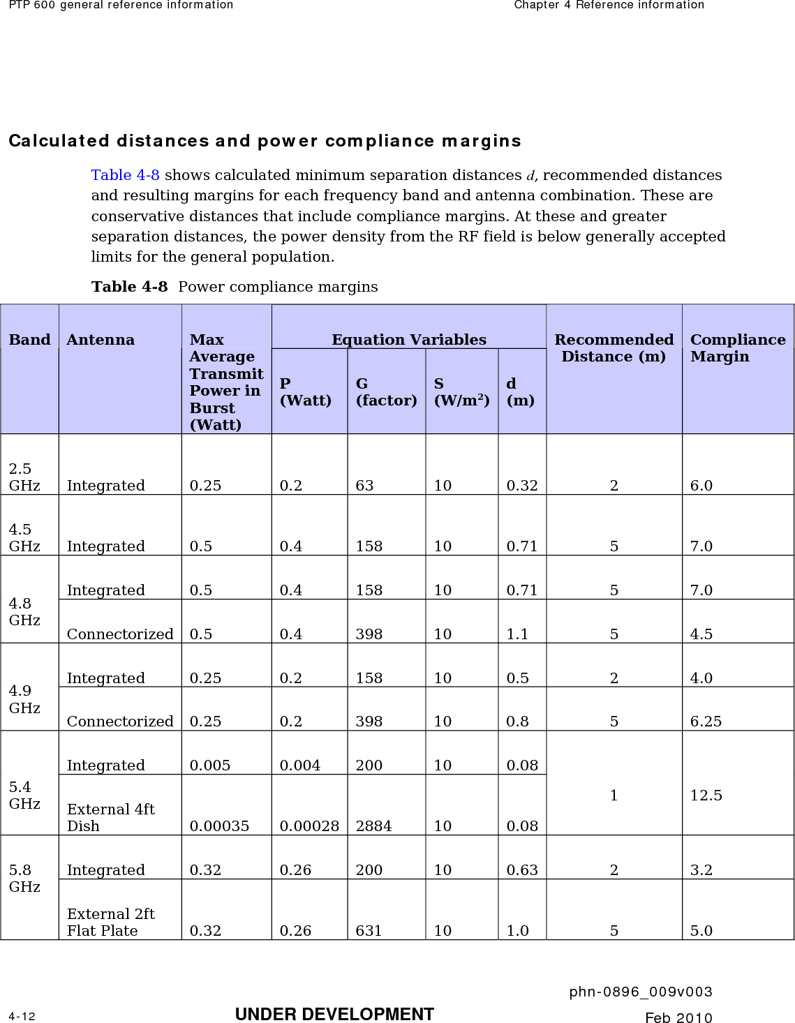
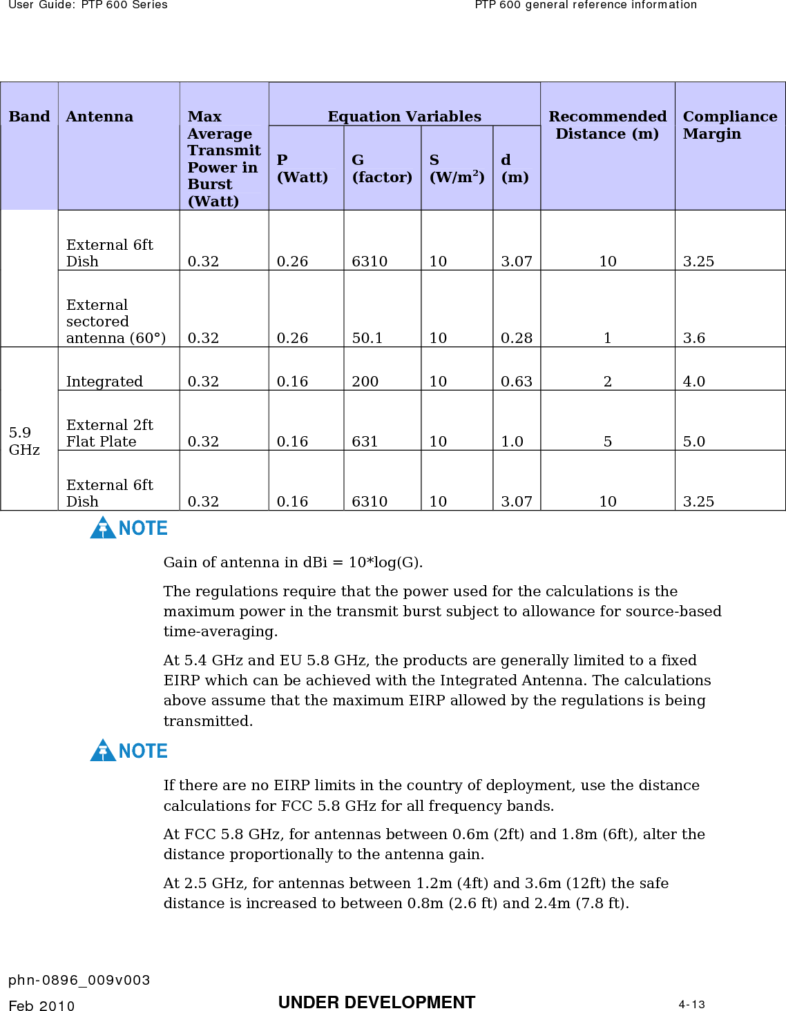
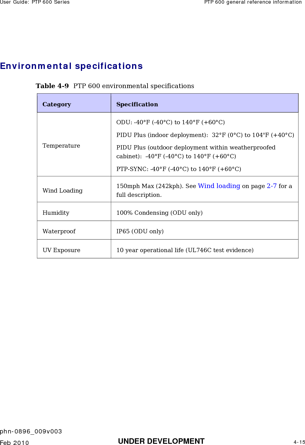
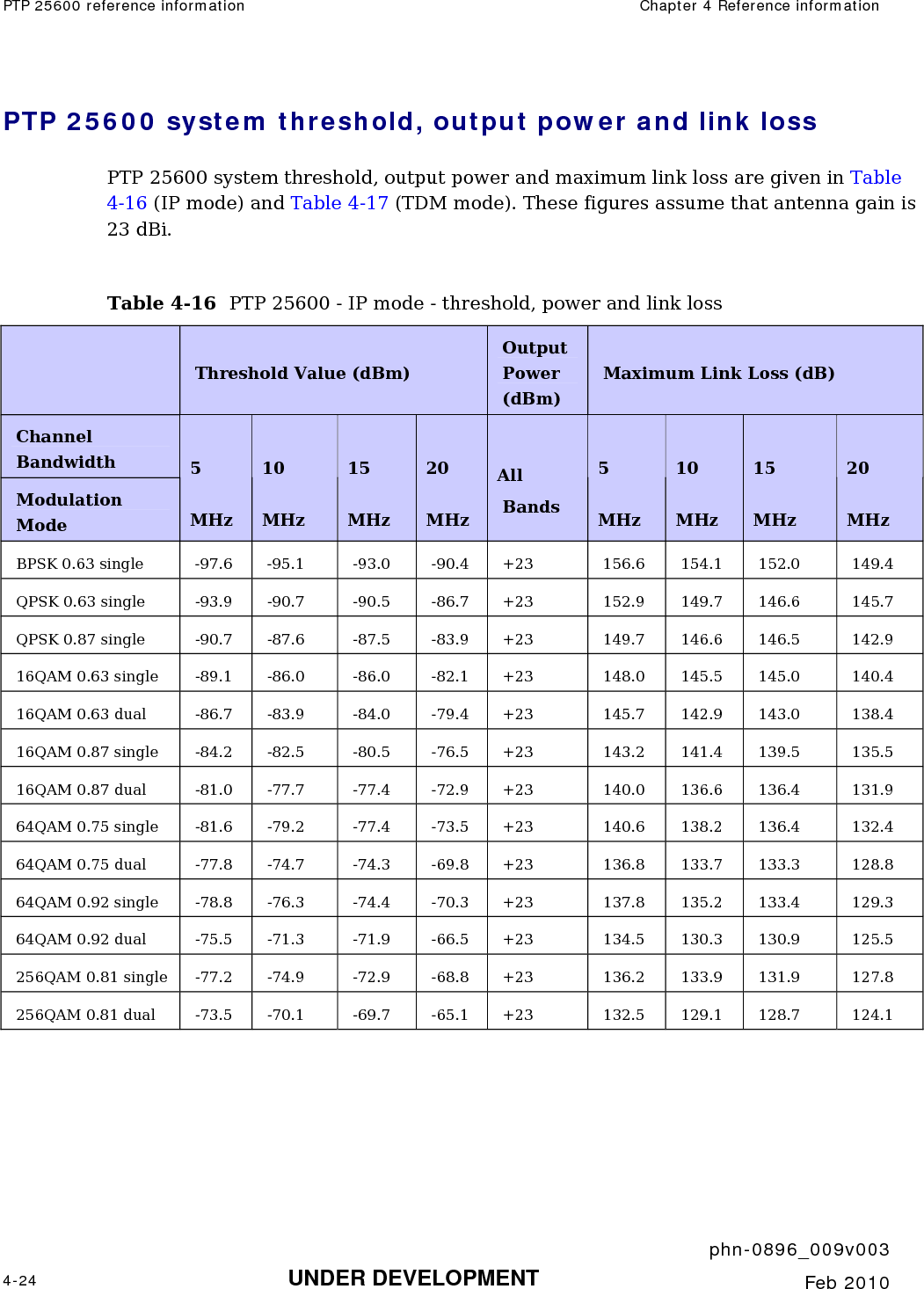
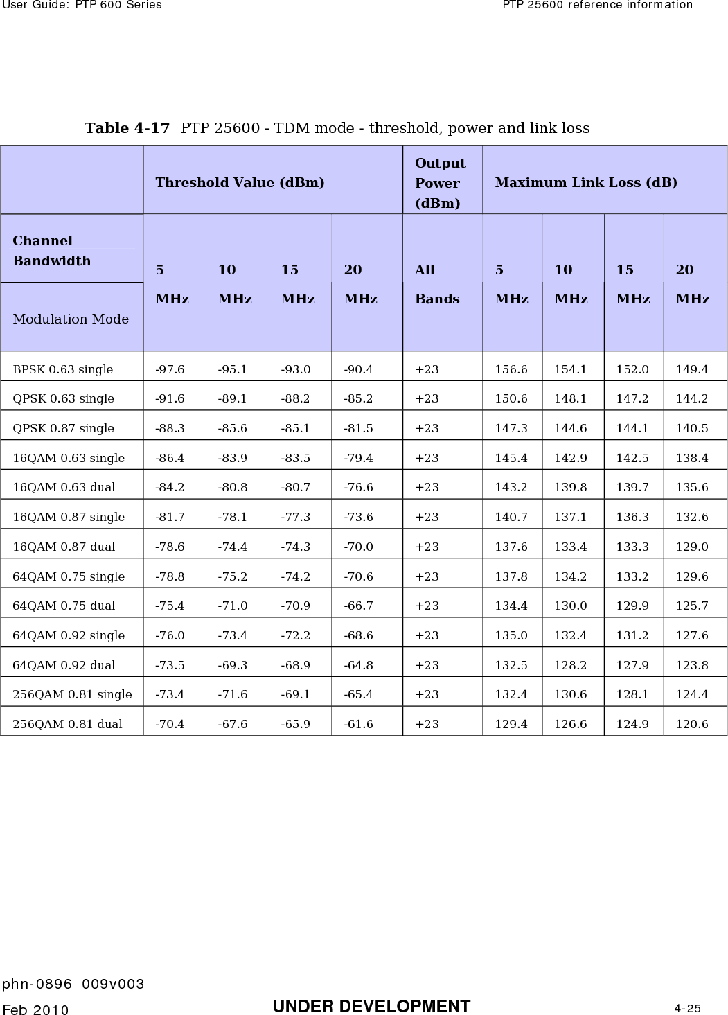
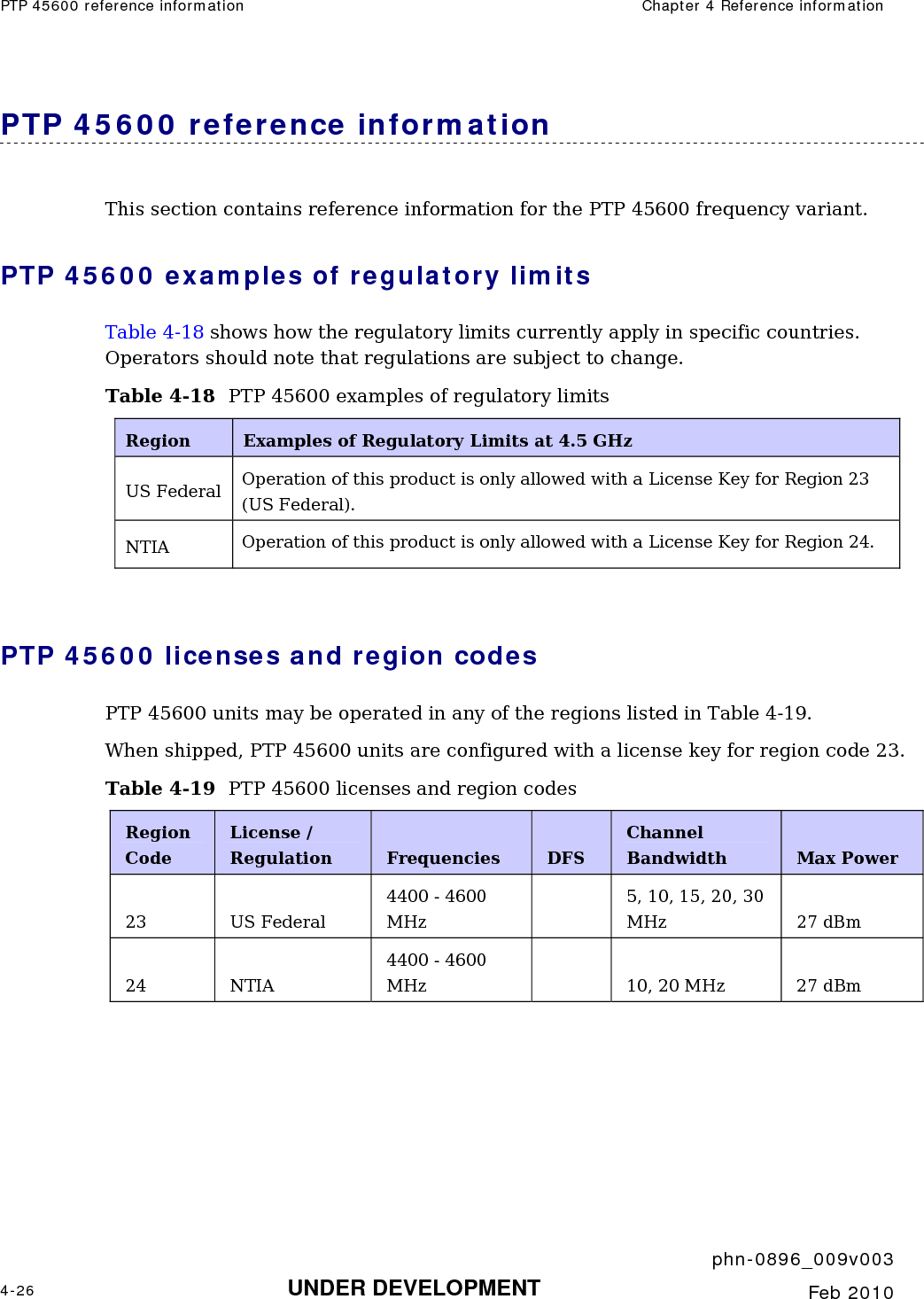
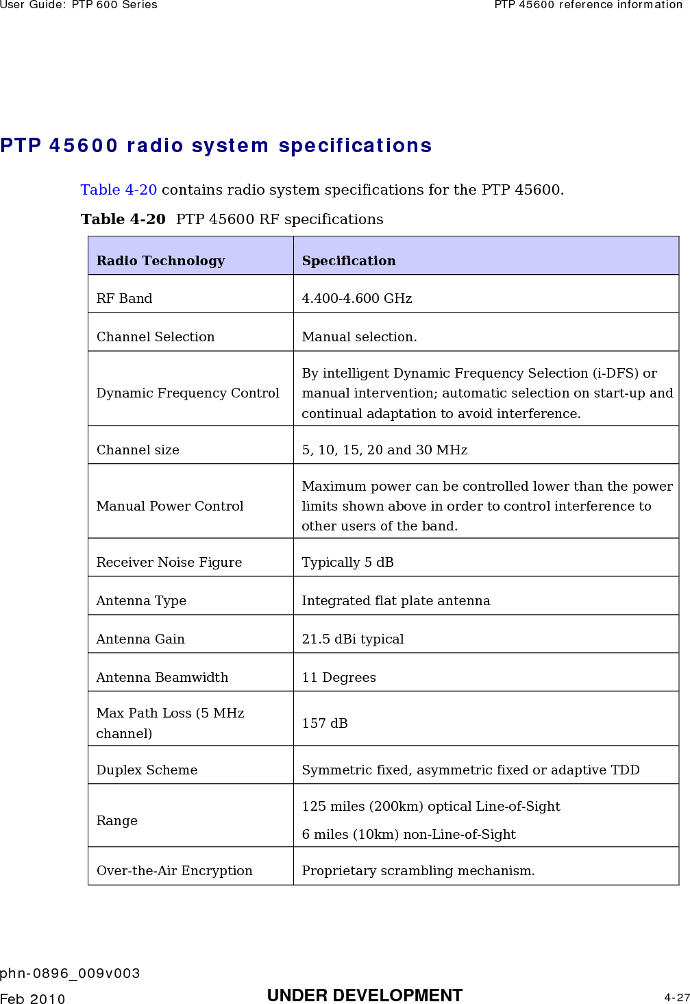
Cambium Networks 58100 Wireless Ethernet Bridge User Manual PTP 600 Series
Cambium Networks Limited Wireless Ethernet Bridge PTP 600 Series
UserManual.wiki
>
Cambium Networks
>
58100 User Manual
>
User Guide Part 1
Contents
1.
Users Manual
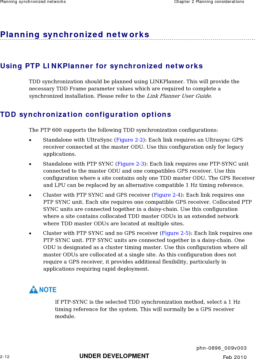
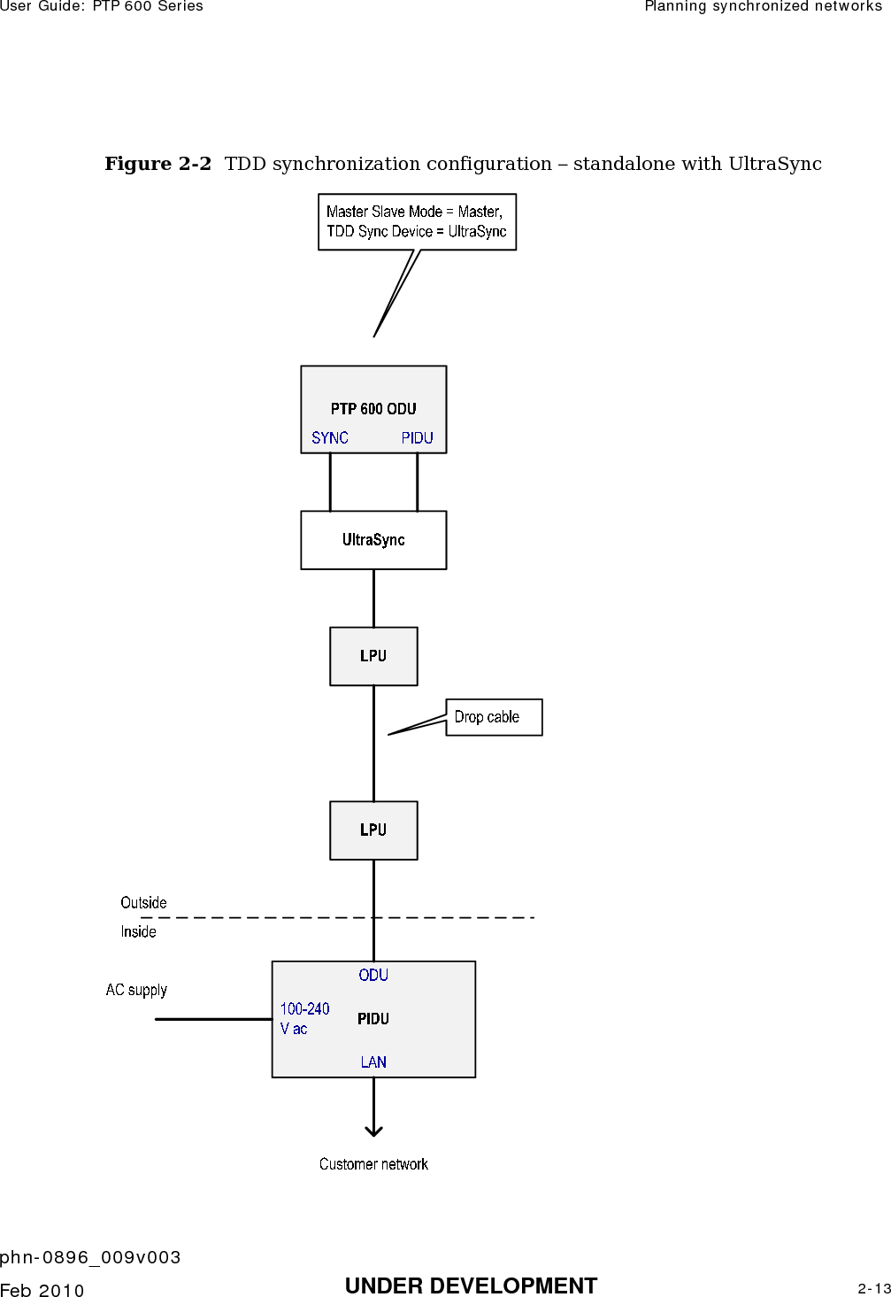
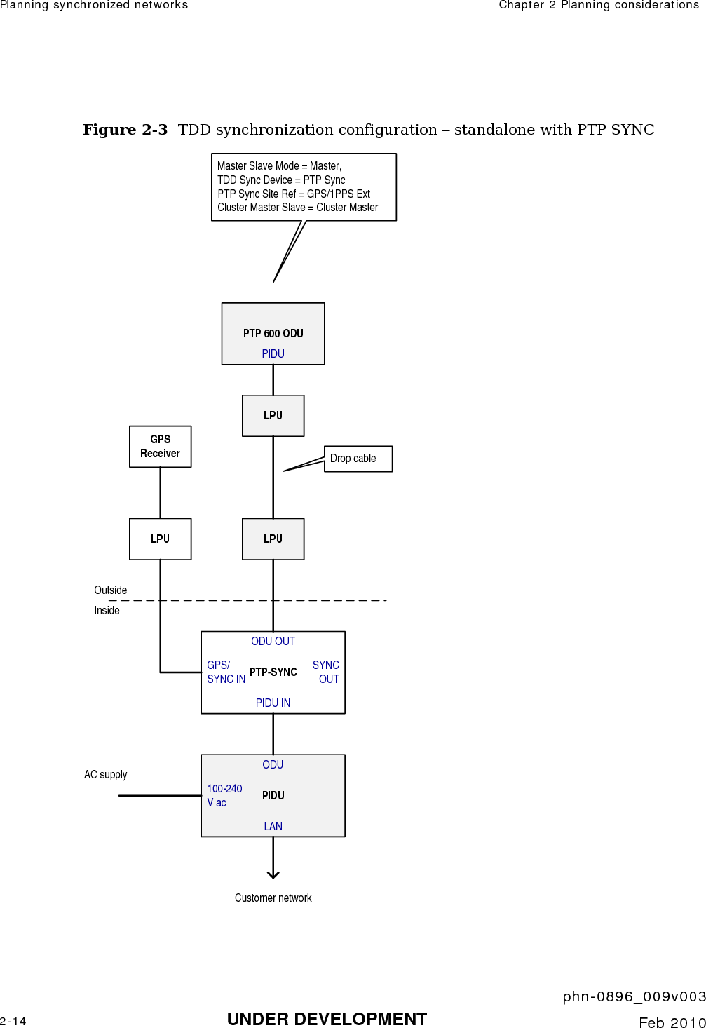
2.
User Guide Part 1
3.
User Guide Part 2
User Guide Part 1
Navigation menu
Upload a User Manual
Namespaces
Wiki Guide
HTML
PDF
Info
Views
User Manual
Discussion / Help
Navigation

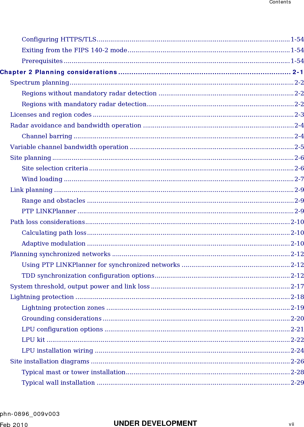

![Outdoor unit (ODU) Chapter 1 Product description phn-0896_009v003 1-8 UNDER DEVELOPMENT Feb 2010 Alternatively, the network connection to a PTP 600 Series can be made using a 1000BaseSX Fiber Optic cable connected directly to the ODU. In this case power is still provided over the 1000BaseT Ethernet connection. In the case of Fiber Optic cable failure the PTP 600 Series will automatically fall back to the copper Ethernet connection (provided the cable length <=100m [330 ft]). “PTP 600 Series Optical Interface Upgrade Kits” can be obtained from your distributor, reseller or system integrator.](https://usermanual.wiki/Cambium-Networks/58100.User-Guide-Part-1/User-Guide-1237757-Page-50.png)

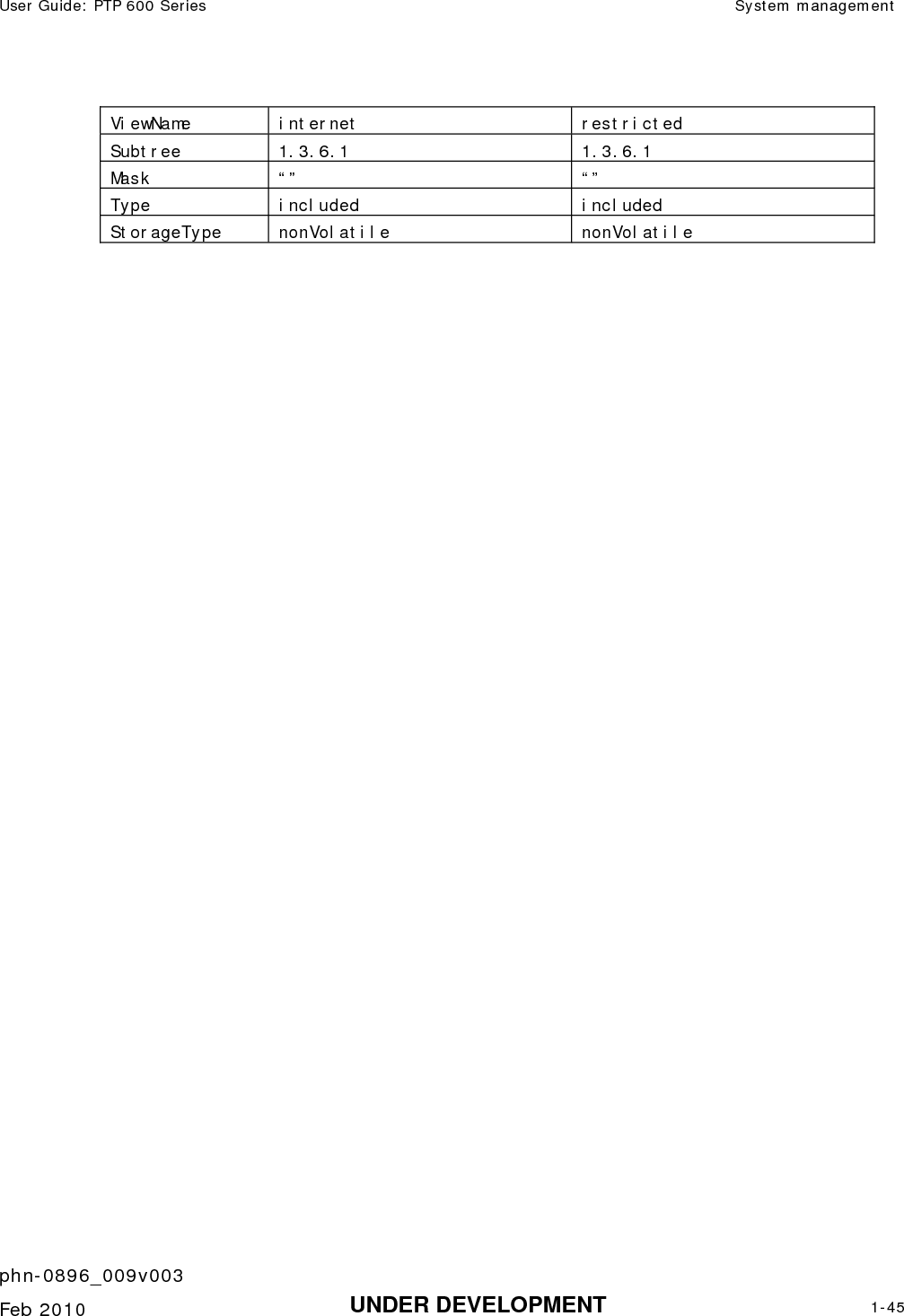
![System management Chapter 1 Product description phn-0896_009v003 1-40 UNDER DEVELOPMENT Feb 2010 • Read only. Identity-based user accounts are enabled in the User Accounts page of the web-based interface. Best-practice passwords PTP 600 allows passwords to be checked for compliance with password best practice. When checking is enabled, passwords must comply with the following: • Passwords are case sensitive • Passwords must contain at least: o One uppercase letter. o One lowercase letter. o One numeral. o One special character. • When the password is changed, the new password must differ from the previous password by at least four characters. Special characters are any of the following: ! \ " # $ % & ' ( ) * + , - . / : ; < = > ? @ [ \ ] ^ _ ` { | } ~ Best-practice passwords can be checked in role-based and identity-based authentication methods. SNMP The management agent supports fault and performance management by means of an SNMP interface. The management agent is compatible with SNMP v1, SNMP v2c, and SNMPv3 using the following MIBs: • PTP 600 enterprise MIB • The system group and the interfaces group from MIB-II, RFC-1213 • The interfaces group and the ifXTable from RFC-2233 • The dot1dBase group and the dot1dBasePortTable group from the Bridge MIB, RFC-1493.](https://usermanual.wiki/Cambium-Networks/58100.User-Guide-Part-1/User-Guide-1237757-Page-82.png)

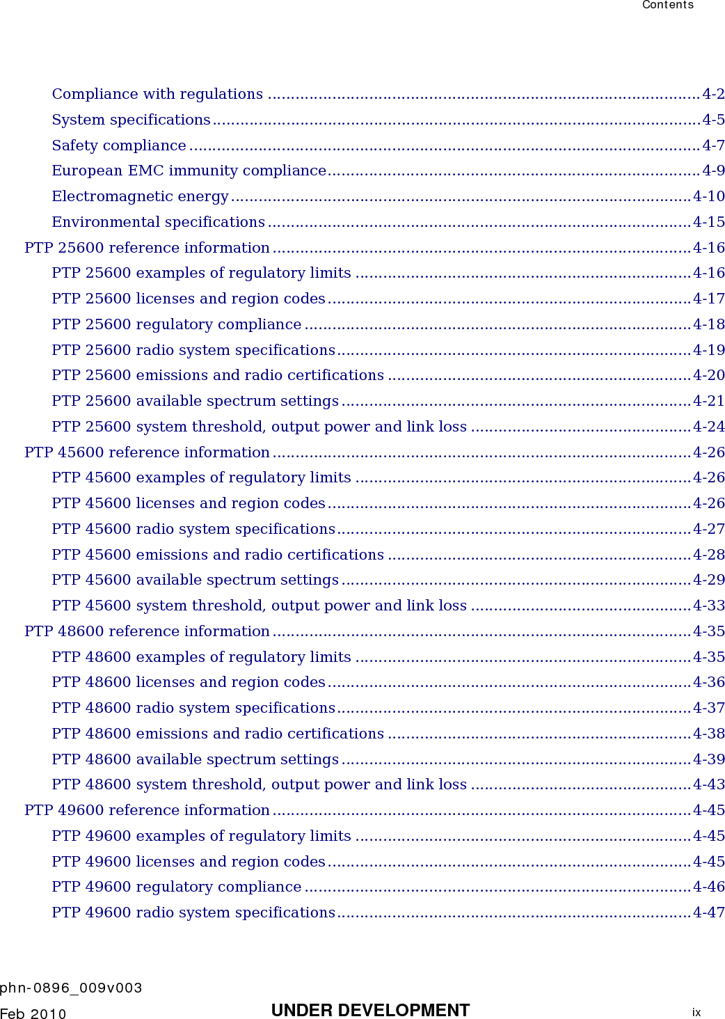
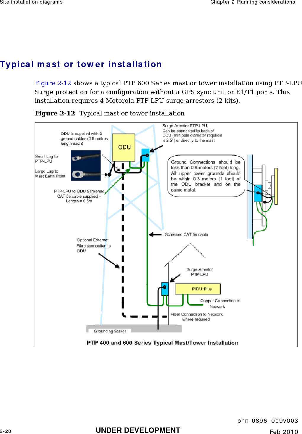
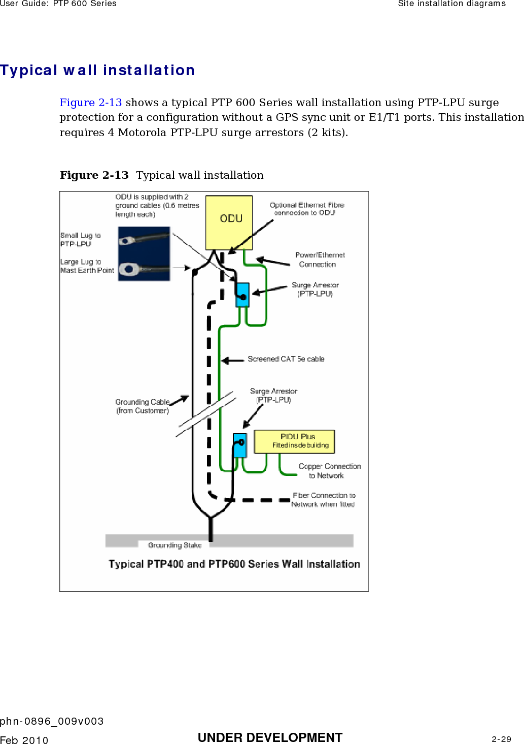
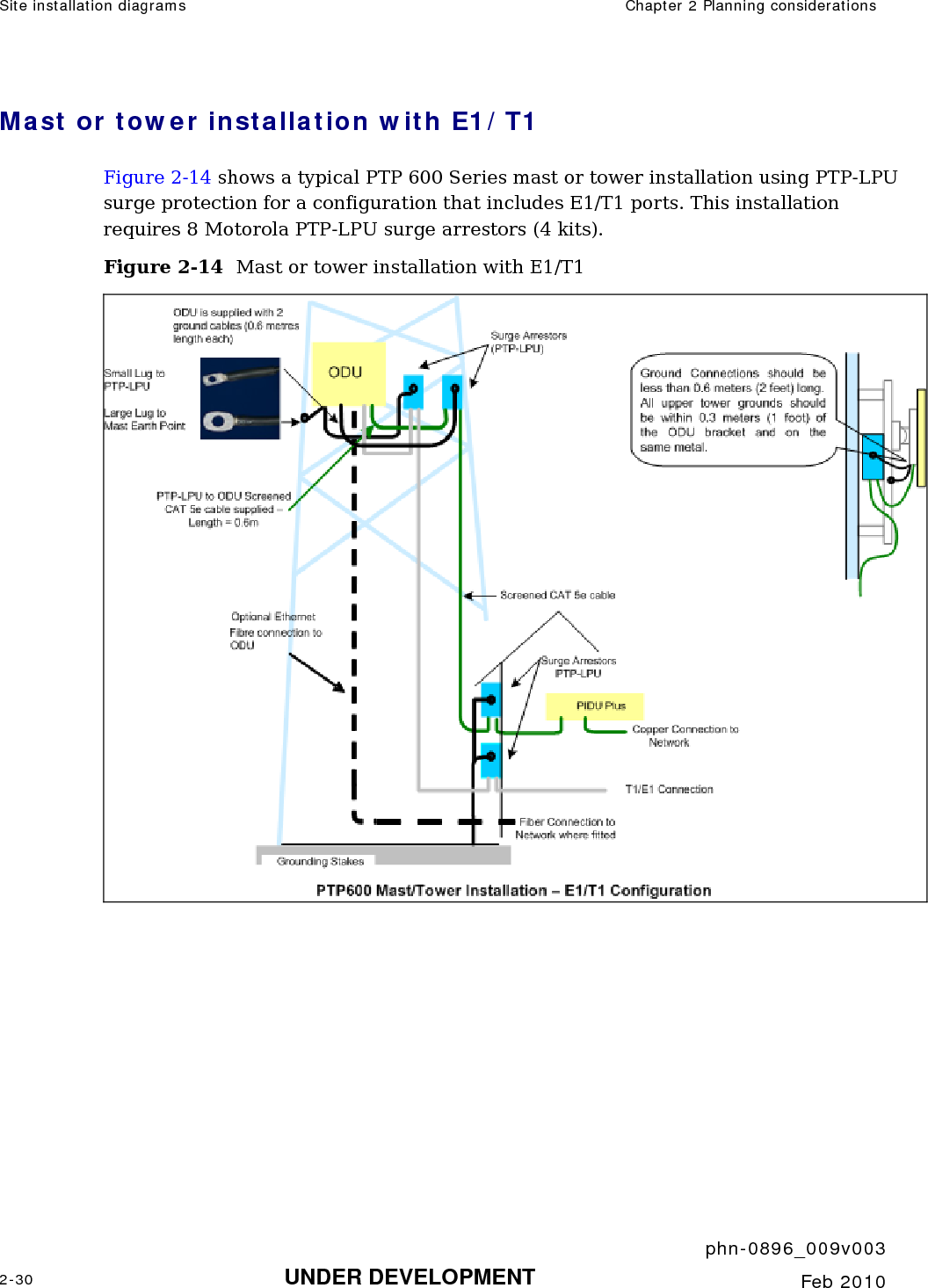
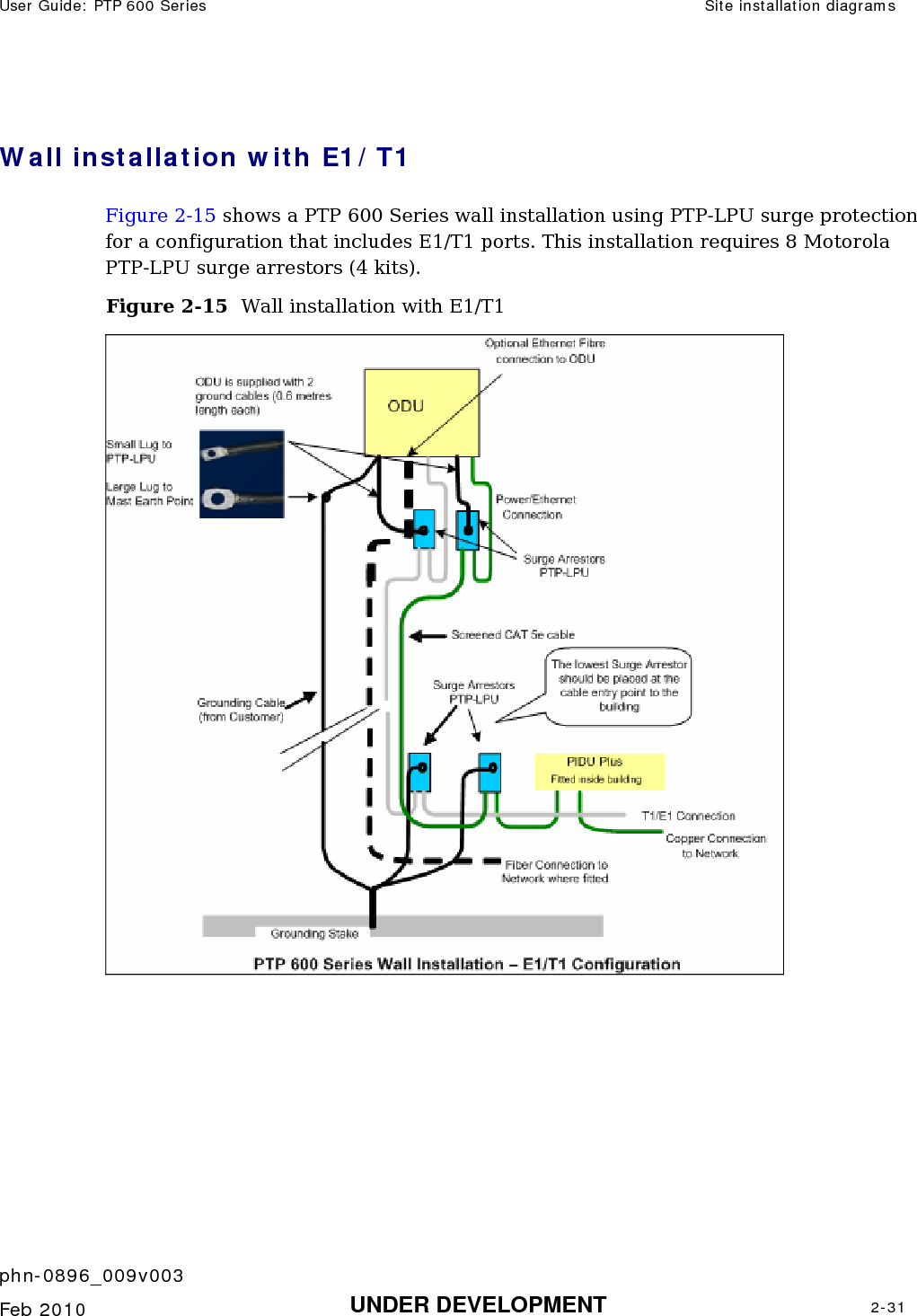
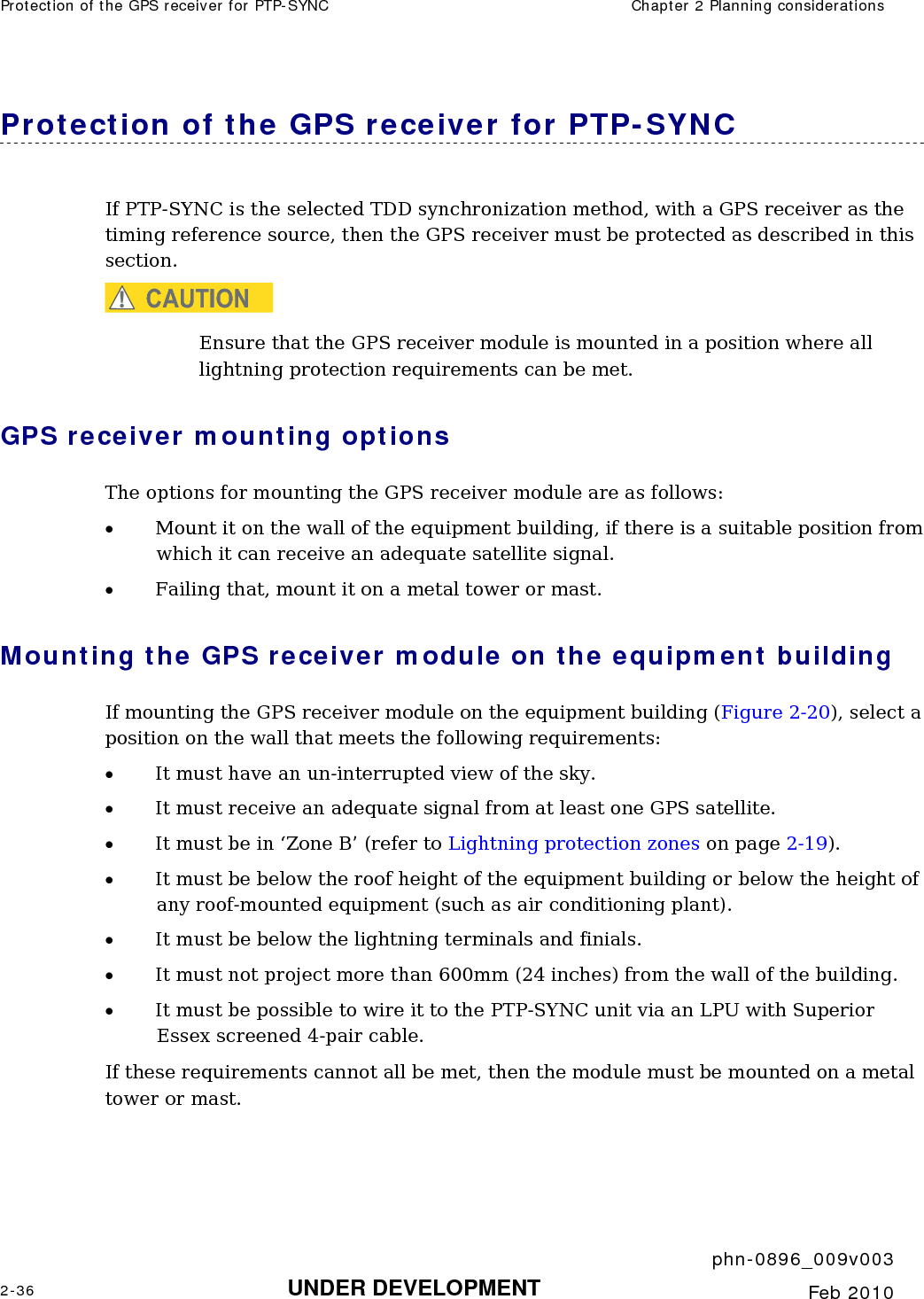
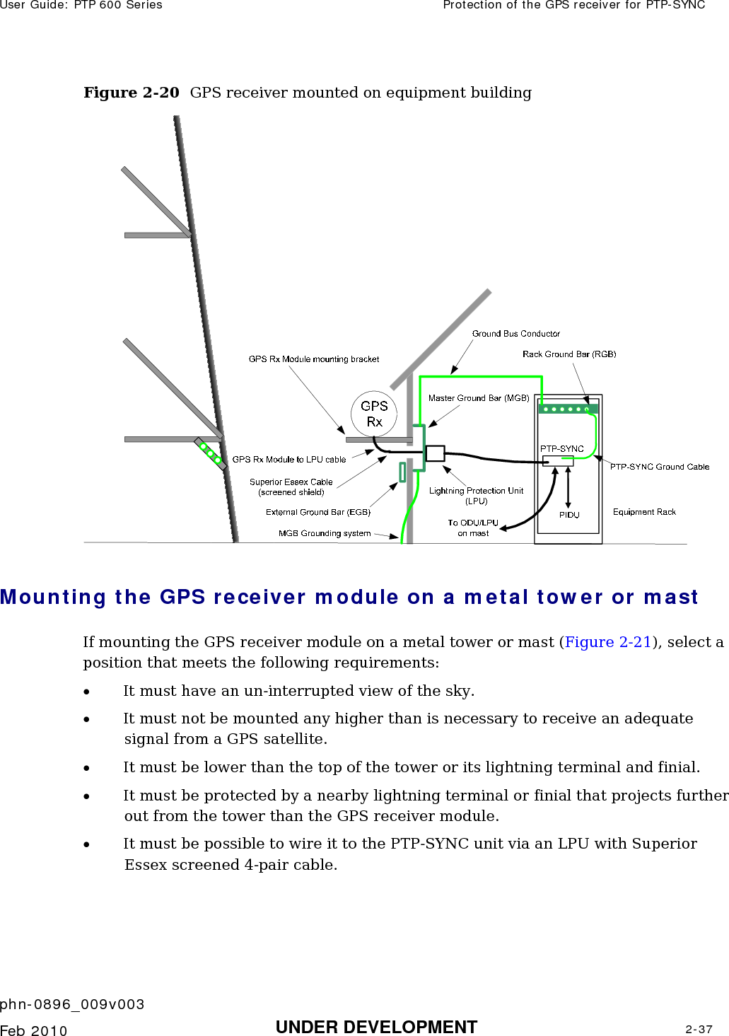
![Site planning Chapter 2 Planning considerations phn-0896_009v003 2-6 UNDER DEVELOPMENT Feb 2010 Site planning Site selection criteria The following are guidelines for selecting the installation location of the ODU and PIDU Plus for a PTP 600 Series. ODU site selection When selecting a site for the ODU the following should be taken into consideration: • It should not be possible for people to stand or walk in front of the antenna • Height and location to achieve the best radio path • Height in relation to other objects with regard to lightning strikes • Aesthetics and planning permission issues • Distance from the ODU and connected Network equipment (Maximum cable run from the ODU to the connected equipment is 100m [330 ft]) • Distance from the PIDU Plus to the ODU (Maximum cable run from the PIDU Plus to the ODU is 300m [990 ft] when using the Fiber interface) • If using the GPS Sync Unit, ensure that it is exposed to an unobstructed path to the sky. Please refer to the “GPS Synchronization Unit Kit” User Manual delivered with the kit. • The effect of strong winds on the installation – see Section Wind loading on page 2-7. PIDU Plus site selection When selecting a site for the PIDU Plus the following should be taken into consideration: • Availability of a mains electricity supply • Accessibility for viewing status indicators and pressing Recovery switch.](https://usermanual.wiki/Cambium-Networks/58100.User-Guide-Part-1/User-Guide-1237757-Page-102.png)


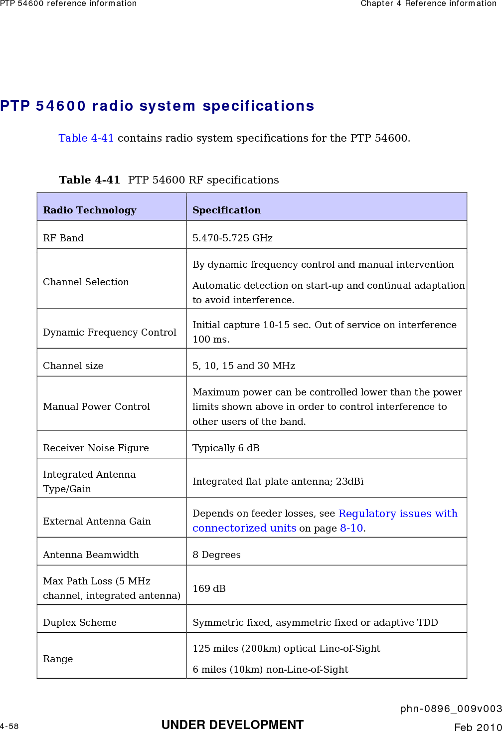
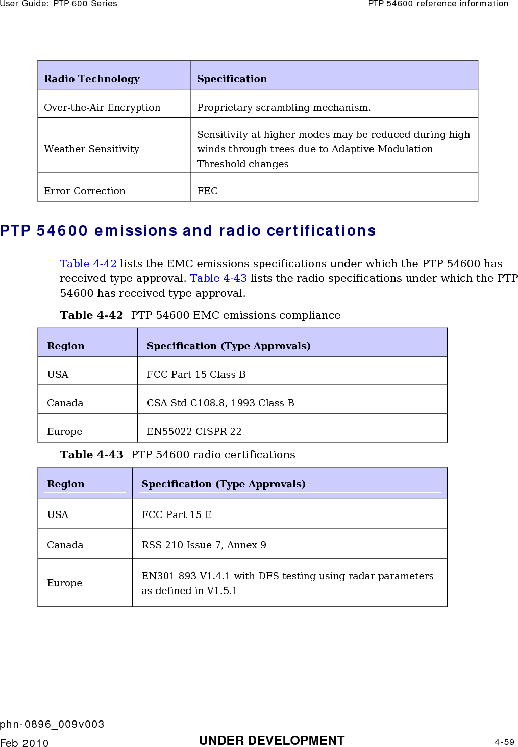
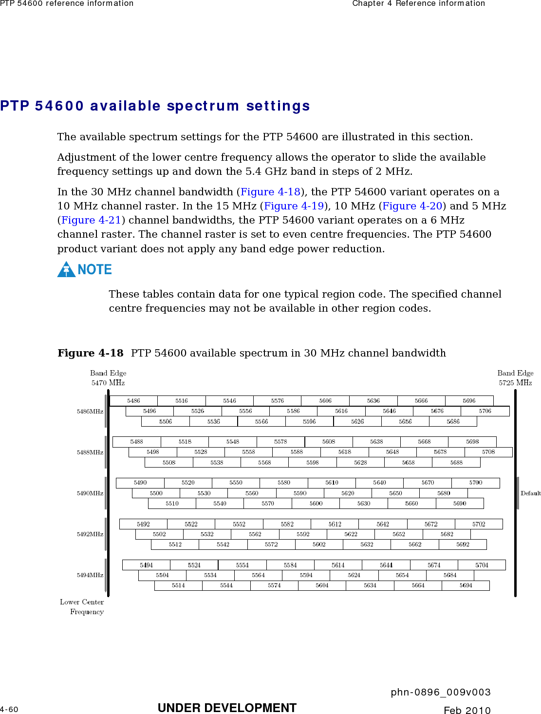
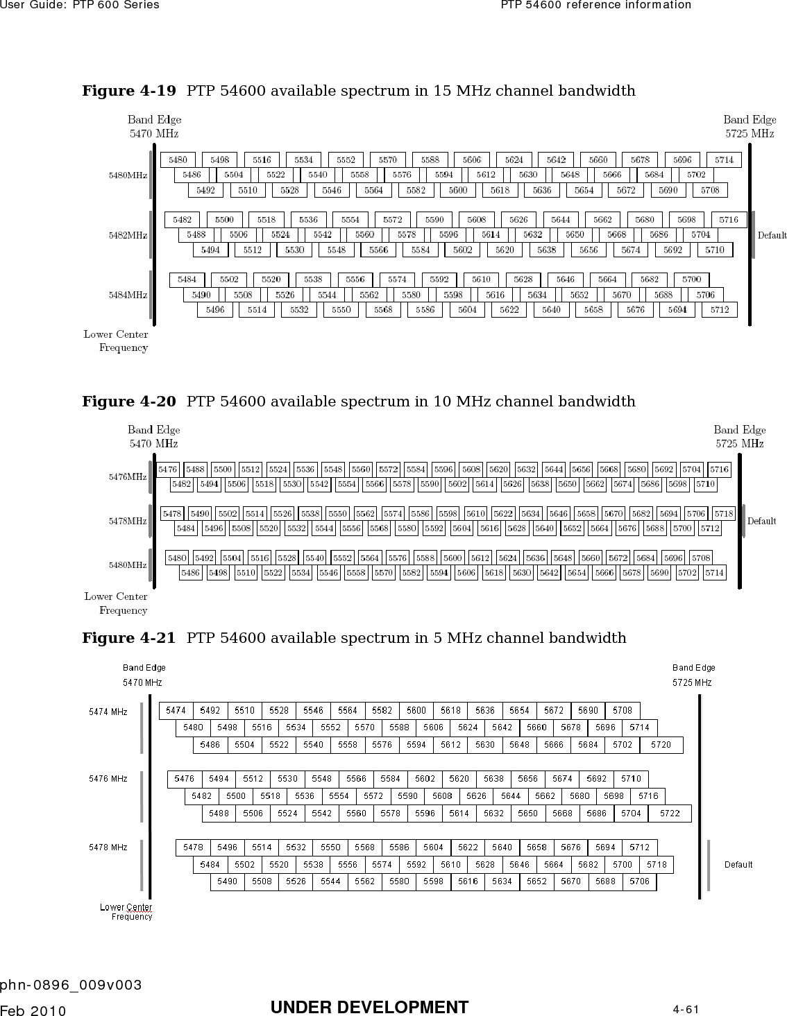
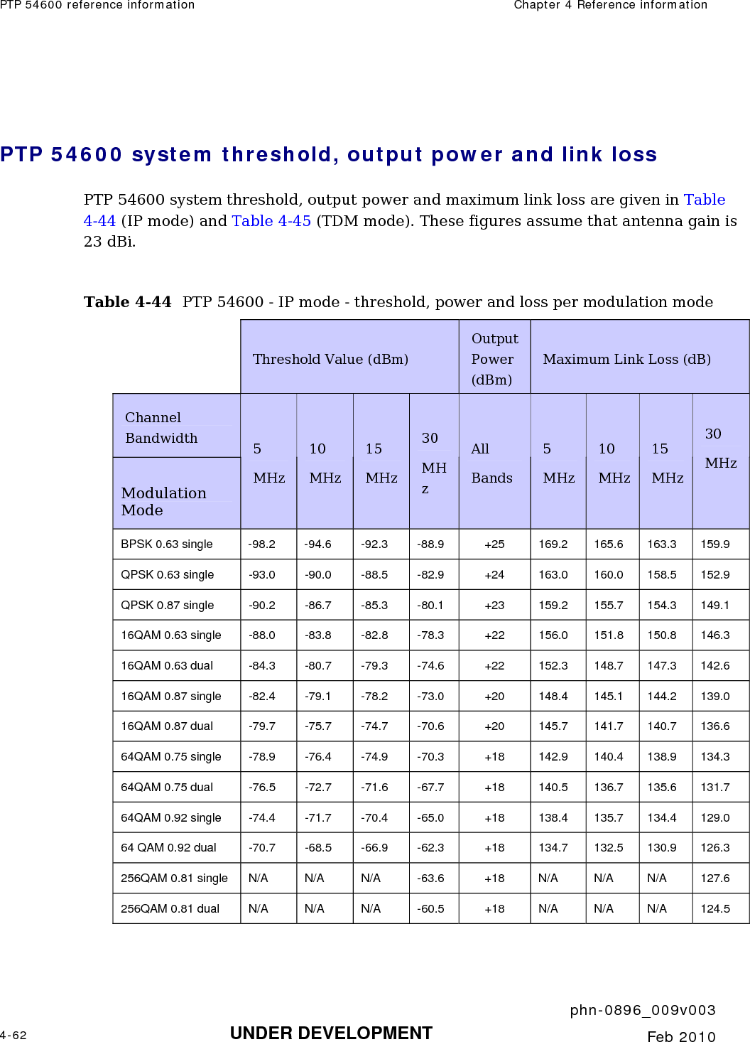
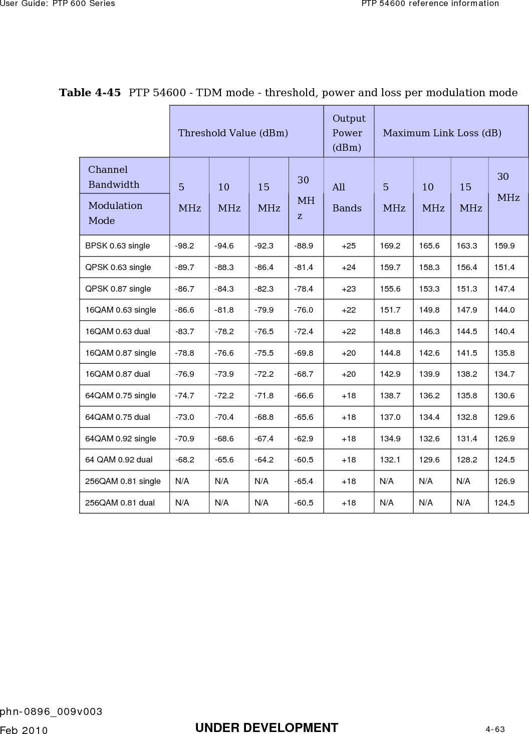
![User Guide: PTP 600 Series PTP 54600 reference information phn-0896_009v003 Feb 2010 UNDER DEVELOPMENT 4-53 PTP 54600 reference information This section contains reference information for the PTP 54600 frequency variant. PTP 54600 examples of regulatory limits Table 4-39 shows how the regulatory limits currently apply in specific countries. Operators should note that regulations are subject to change. Table 4-39 PTP 54600 examples of regulatory limits Region Examples of Regulatory Limits at 5.4GHz FCC Operation of this product is only allowed with a License Key for Region 12. This implements Radar Detection in accordance with FCC Regulations and limits the EIRP to the regulatory limits below: EIRP ≤ Max of [(17 +10 x Log(Channel BW)) and 30] dBm. ETSI Operation of this product is only allowed with a License Key for Region 26. This implements Radar Detection, including barring of the band from 5600 MHz to 5650 MHz and limits the EIRP to the regulatory limits below: EIRP ≤ Max of [(17 +10 x Log(Channel BW)) and 30] dBm Australia, Canada Operation of this product is only allowed with a License Key for Region 13. This implements Radar Detection, including barring of the band from 5600 MHz to 5650 MHz and limits the EIRP to the regulatory limits below: EIRP ≤ Max of [(17 +10 x Log(Channel BW)) and 30] dBm Thailand Operation of this product is only allowed with a License Key for Region 20 (30 dBm or 1W EIRP) Korea Operation of this product is only allowed with a License Key for Region 21 (28 dBm EIRP (15 MHz), 27 dBm EIRP (10 MHz), 24 dBm EIRP (5 MHz)). General Notice Applicable to Europe – 5.4 GHz This equipment complies with the essential requirements for the EU R&E Directive 1999/5/EC.](https://usermanual.wiki/Cambium-Networks/58100.User-Guide-Part-1/User-Guide-1237757-Page-201.png)
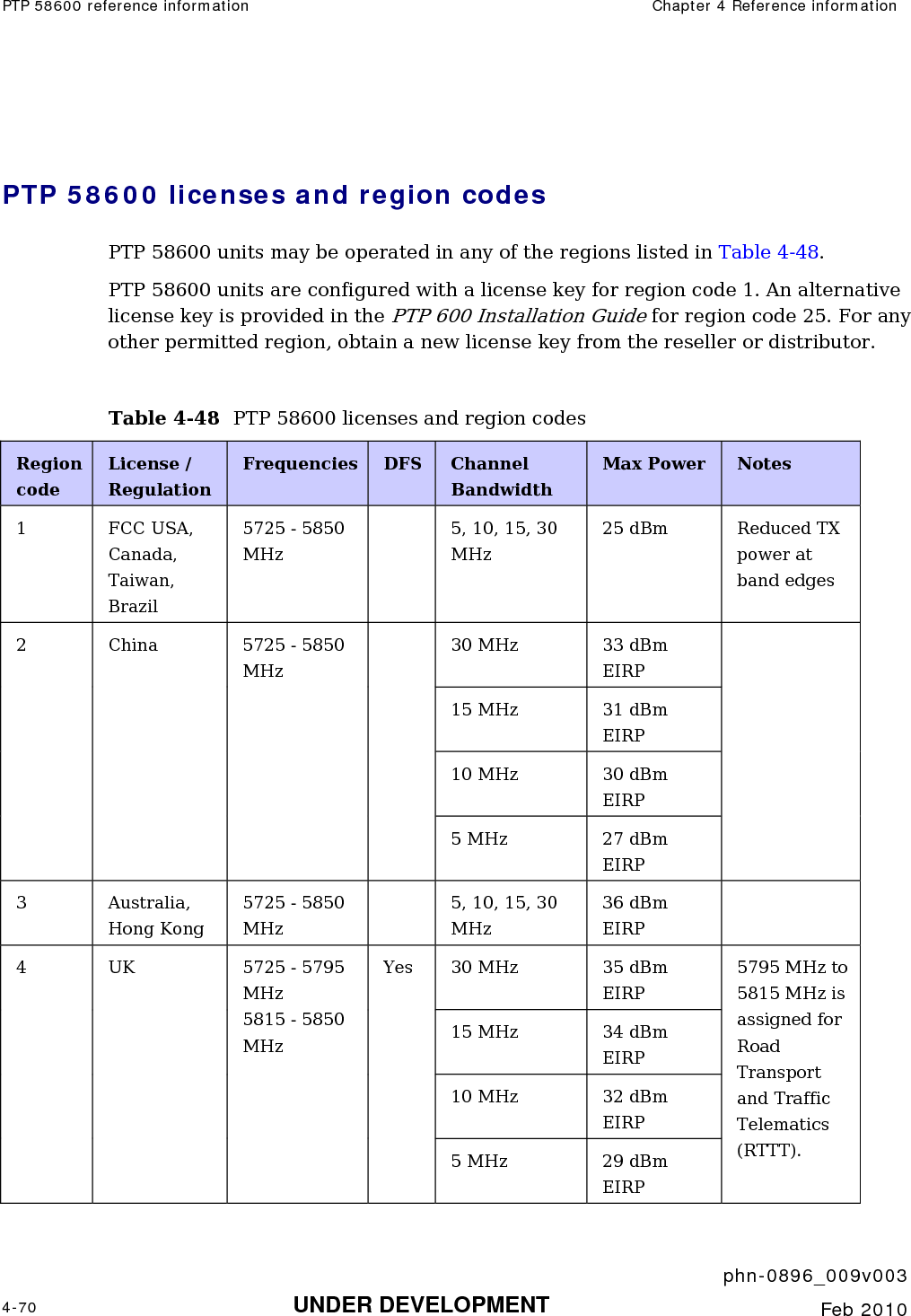
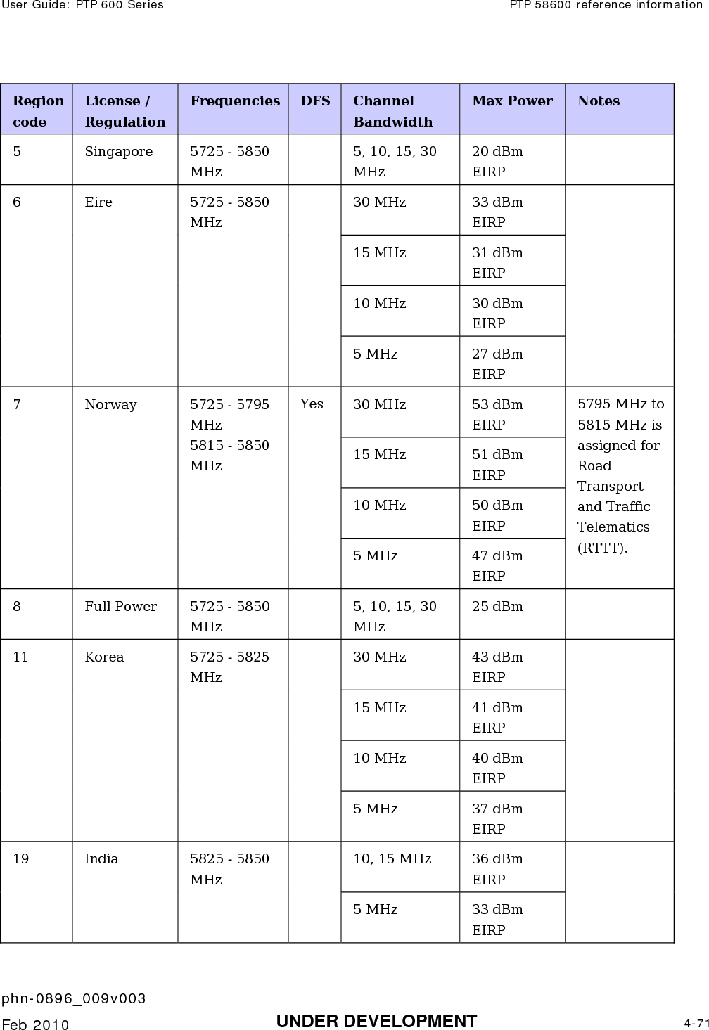
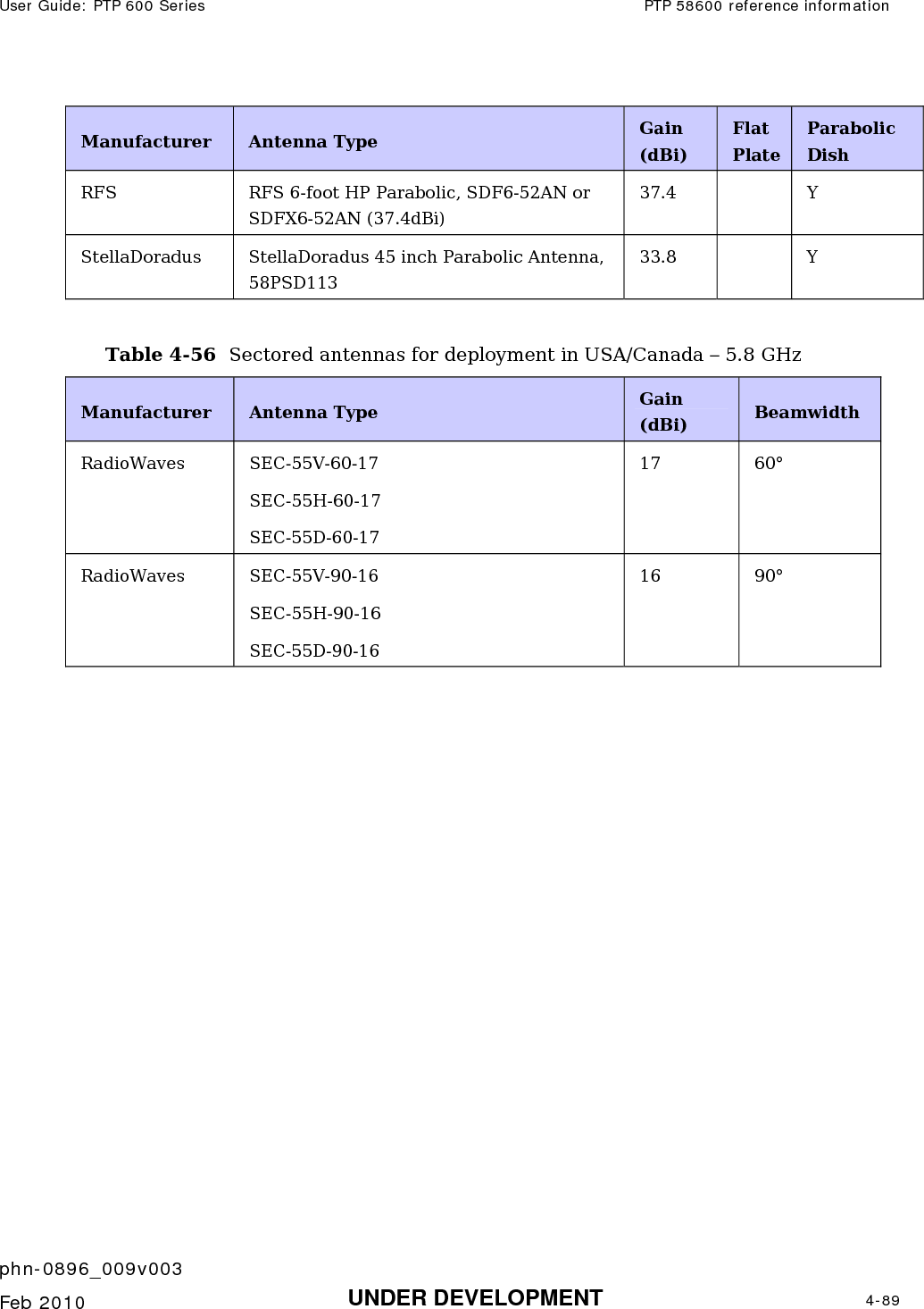
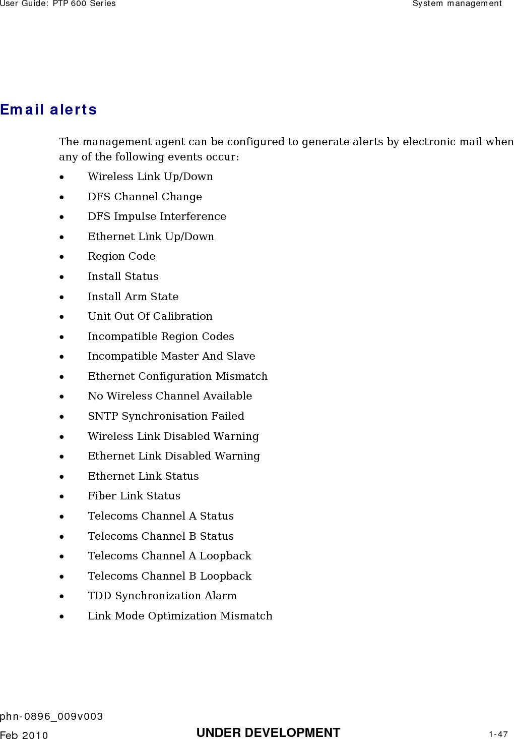
![User Guide: PTP 600 Series PTP 58600 reference information phn-0896_009v003 Feb 2010 UNDER DEVELOPMENT 4-67 PTP 58600 reference information This section contains reference information that is specific to the PTP 58600 frequency variant. PTP 58600 examples of regulatory limits Table 4-47 shows how the regulatory limits currently apply in specific countries. Operators should note that regulations are subject to change. Table 4-47 PTP 58600 examples of regulatory limits Region Examples of Regulatory Limits at 5.8GHz USA/ Canada/ Taiwan/ Brazil Equipment can be operated in any mode, best results will be obtained using Region 1 settings. There are some limitations on the use of antennas above 4ft diameter plus a band edge power reduction. China Operation of this product is only allowed with a License Key for Region 2 (33 dBm or 2W EIRP). Australia Operation of this product is only allowed with a License Key for Region 3 (36 dBm or 4W EIRP). Hong Kong Operation of this product is only allowed with a License Key for Region 3 (36 dBm or 4W EIRP). UK Operation of this product is allowed with a License Key for Region 4. This implements Radar Detection with barring of the band from 5795 MHz to 5815 MHz and above 5850 MHz. It limits the EIRP to the Regulatory Limits below: EIRP ≤ Max of [(23 +10 x Log(Channel BW)) and 36] dBm Singapore Operation of this product is only allowed with a License Key for Region 5 (20 dBm or 100mW EIRP). Eire Operation of this product is only allowed with a License Key for Region 6 (33 dBm or 2W EIRP). The lower power limits are lower in narrower bandwidths. Korea Operation of this product is only allowed with a License Key for Region 11 (43 dBm or 20W EIRP).](https://usermanual.wiki/Cambium-Networks/58100.User-Guide-Part-1/User-Guide-1237757-Page-215.png)
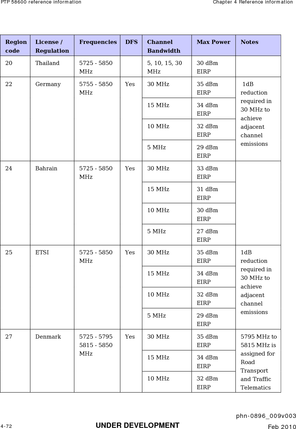
![PTP 58600 reference information Chapter 4 Reference information phn-0896_009v003 4-68 UNDER DEVELOPMENT Feb 2010 Region Examples of Regulatory Limits at 5.8GHz India Operation of this product is only allowed with a License Key for Region 19 (36 dBm or 4W EIRP at 15 MHz and 10 MHz and 33 dBm or 2 W EIRP at 5 MHz channel bandwidth). Thailand Operation of this product is only allowed with a License Key for Region 20 (30 dBm or 1W EIRP). Germany Operation of this product is only allowed with a License Key for Region 22. This limits the band of operation to 5755 MHz to 5850 MHz and limits the EIRP to the Regulatory Limits below: EIRP ≤ Max of [(23 +10 x Log(Channel BW)) and 36] dBm Bahrain Operation of this product is allowed with a License Key for Region 24 . This limits the EIRP to the Regulatory Limits below: EIRP ≤ Max of [(20 +10 x Log(Channel BW)) and 33] dBm Norway Under Norway Regulations, operation of this product is only allowed with a License Key for Region 7. This implements Radar Detection and limits the EIRP to the Regulatory Limits below: EIRP ≤ Max of [(40 +10 x Log(Channel BW)) and 53] dBm Spectral density at border between Norway and neighboring countries shall not exceed -122,5 dBW/m2 measured with a reference bandwidth of 1 MHz. General Notice Applicable to Europe – 5.8 GHz This equipment complies with the essential requirements for the EU R&E Directive 1999/5/EC. The use of 5.8GHz for Point to Point radio links is not harmonized across the EU and currently the product may only be deployed in the UK, Eire (IRL), Germany, Denmark and Norway. However, the regulatory situation in Europe is changing and the radio spectrum may become available in other countries in the near future. Please contact Motorola for the latest situation.](https://usermanual.wiki/Cambium-Networks/58100.User-Guide-Part-1/User-Guide-1237757-Page-216.png)