Cambium Networks XN12 Wireless LAN Array User Manual XN PDF
Xirrus, Inc. Wireless LAN Array XN PDF
Contents
- 1. Users Manual 1of5
- 2. Users Manual 2of5
- 3. Users Manual 3of5
- 4. Users Manual 4of5
- 5. Users Manual 5of5
- 6. A Pages 1 to 125 from ArrayGuide Rel4 SS Dec02 2008
- 7. B Pages 126 to 225 from ArrayGuide Rel 4 SS Dec02 2008
- 8. C Pages 226 to 350 from ArrayGuide Rel4 SS Dec02 2008
- 9. D Pages 351 to 496 from ArrayGuide Rel4 SS Dec02 2008 Small 5
- 10. XN Guide small 1 of 5 revised
Users Manual 4of5

Wi-Fi Array
Configuring the Wi-Fi Array 167
•Pre-Shared Key—users must manually enter a key (passphrase)
on the client side of the wireless network that matches the key
stored by the administrator in the Array.
This method should be used only for smaller networks when a
RADIUS server is unavailable. If PSK must be used, choose a
strong passphrase containing between 8 and 63 characters (20 is
preferred). Always use a combination of letters, numbers and
special characters. Never use English words separated by spaces.
•RADIUS 802.1x with EAP—802.1x uses a RADIUS server to
authenticate large numbers of clients, and can handle different
EAP (Extensible Authentication Protocol) authentication
methods, including EAP-TLS, EAP-TTLS, EAP-PEAP, and LEAP-
Passthrough. The RADIUS server can be internal (provided by
the Wi-Fi Array) or external. An external RADIUS server offers
more functionality and security, and is recommended for large
deployments. When using this method, user names and
passwords must be entered into the RADIUS server for user
authentication.
•MAC Address ACLs (Access Control Lists)—MAC address
ACLs provide a list of client adapter MAC addresses that are
allowed or denied access to the wireless network. Access Control
Lists work well when there are a limited number of users—in this
case, enter the MAC address of each user in the Allow list. In the
event of a lost or stolen MAC adapter, enter the affected MAC
address in the Deny list.
The Wi-Fi Array will accept up to 1,000 ACL entries.
Wi-Fi Array
168 Configuring the Wi-Fi Array
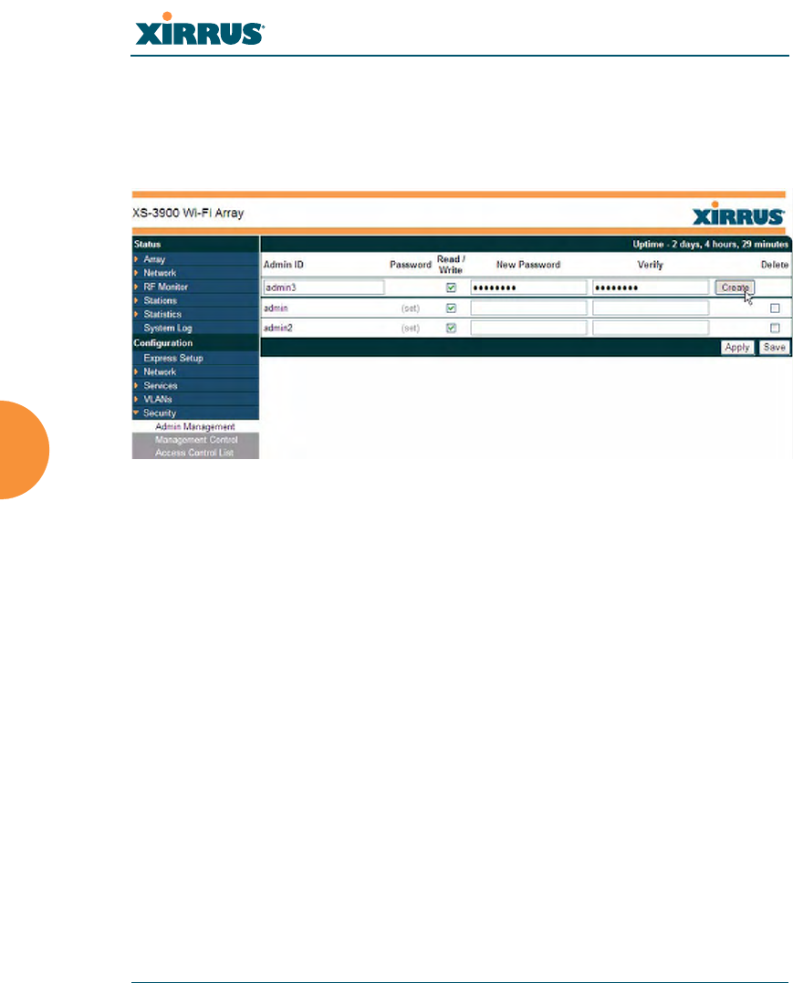
Admin Management
This window allows you to manage network administrator accounts (create,
modify and delete). It also allows you to limit account access to a read only status.
When finished, click on the Save button to save your changes.
Figure 106. Admin Management
Procedure for Creating or Modifying Network Administrator Accounts
1. Admin ID: Enter the login name for a new network administrator ID.
2. Read/Write: Choose Read/Write if you want to give this administrator ID
full read/write privileges, or choose Read to restrict this user to read only
status. In the read only mode, administrators cannot save changes to
configurations.
3. User Password: Enter a password for this ID.
4. Verify Password: Re-enter the password in this field to verify that you
typed the password correctly. If you do not re-enter the correct password,
an error message is displayed).
5. Click on the Create button to add this administrator ID to the list.
6. Click Apply to apply modified settings to this session, or click Save to
apply your changes and make them permanent.
Wi-Fi Array
Configuring the Wi-Fi Array 169
See Also
External Radius
Global Settings (IAP)
Internal Radius
Management Control
Security
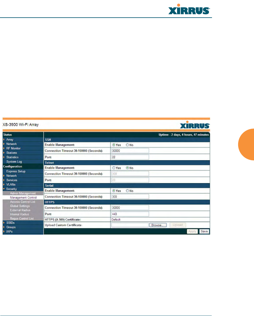
Management Control
This window allows the Array management interfaces to be enabled and disabled
and their inactivity time-outs set. The supported range is 300 (default) to 100,000
seconds.
Figure 107. Management Control
Procedure for Configuring Management Control
1. SSH:
a. Enable Management: Choose Yes to enable management of the
Array over a Secure Shell (SSH) connection, or No to disable this
feature.

Wi-Fi Array
170 Configuring the Wi-Fi Array
b. Connection Timeout 30-100000 (Seconds): Enter a value in this field
to define the timeout (in seconds) before your SSH connection is
disconnected. The value you enter here must be between 30 seconds
and 100,000 seconds.
c. Port: Enter a value in this field to define the port used by SSH.
The default port is 22.
2. Telnet:
a. Enable Management: Choose Yes to enable Array management over
a Telnet connection, or No to disable this feature. SSH offers a more
secure connection than Telnet, and is recommended over Telnet.
b. Connection Timeout 30-100000 (Seconds): Enter a value in this field
to define the timeout (in seconds) before your Telnet connection is
disconnected. The value you enter here must be between 30 seconds
and 100,000 seconds.
c. Port: Enter a value in this field to define the port used by Telnet.
The default port is 23.
3. Serial
a. Enable Management: Choose Yes to enable management of the
Array via a serial connection, or choose No to disable this feature.
b. Connection Timeout 30-100000 (Seconds): Enter a value in this field
to define the timeout (in seconds) before your serial connection is
disconnected. The value you enter here must be between 30 seconds
and 100,000 seconds.
4. HTTPS
a. Connection Timeout 30-100000 (Seconds): Enter a value in this field
to define the timeout (in seconds) before your HTTPS connection is
disconnected. The value you enter here must be between 30 seconds
and 100,000 seconds. Management via HTTPS (i.e., the Web
Management Interface) cannot be disabled on this window. To
disable management over HTTPS, you must use the Command Line
Interface.

Wi-Fi Array
Configuring the Wi-Fi Array 171
b. Port: Enter a value in this field to define the port used by SSH.
The default port is 443.
c. HTTPS (X.509) Certificate: This read-only field displays the current
X.509 certificate in use.
d. Upload Custom Certificate: If you wish to use a custom certificate,
use the Browse button to locate the certificate file, then click Upload
to copy it to the Array. The Array’s web server will be restarted and
will pick up the new certificate. This will terminate any current web
sessions, and the you will need to re-connect and re-login to the
Array.
5. Click on the Apply button to apply the new settings to this session, or
click Save to apply your changes and make them permanent.
See Also
Network Interfaces - to enable/disable management over an Ethernet interface
Global Settings (IAP) - to enable/disable management over IAPs
Admin Management
External Radius
Global Settings (IAP)
Internal Radius
Access Control List
Security
Wi-Fi Array
172 Configuring the Wi-Fi Array
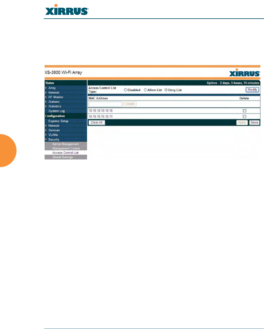
Access Control List
This window allows you to create new station access lists, delete existing lists,
and add/remove MAC addresses. When finished, click on the Save button to
save your changes.
Figure 108. Access Control List
Procedure for Configuring Access Control Lists
1. Access Control List Type: Select Disabled to disable the Access Control
List, or select the Access Control List type—either Allow List or Deny
List. Then click Apply to apply your changes.
•Allow List: Only allows these MAC addresses to associate to the
Array.
•Deny List: Allows all MAC addresses except the addresses
defined in this list.
2. MAC Address: If you want to add a MAC address to the ACL, enter the
new MAC address here, then click on the Create button. The MAC
address is added to the ACL.
#In addition to these lists, other authentication methods (for
example, RADIUS) are still enforced for users.

Wi-Fi Array
Configuring the Wi-Fi Array 173
3. Delete: You can delete selected MAC addresses from this list by checking
their Delete buttons, then clicking Apply or Save.
4. Click on the Apply button to apply the new settings to this session, or
click Save to apply your changes and make them permanent.
See Also
External Radius
Global Settings (IAP)
Internal Radius
Management Control
Security
Station Status Windows (list of stations that have been detected by the Array)
Wi-Fi Array
174 Configuring the Wi-Fi Array
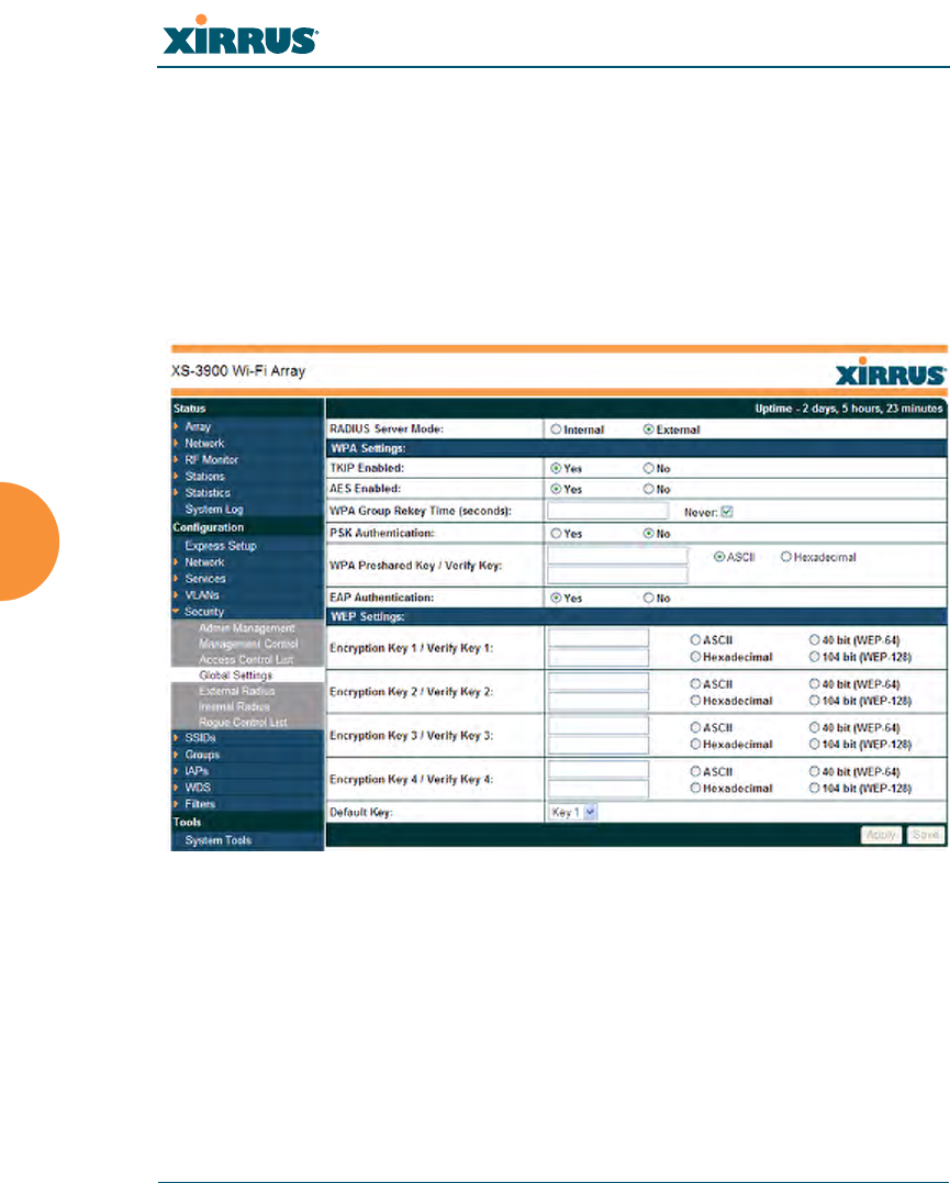
Global Settings
This window allows you to establish the security parameters for your wireless
network, including WEP, WPA, WPA2 and RADIUS authentication. When
finished, click on the Apply button to apply the new settings to this session, or
click Save to apply your changes and make them permanent.
For additional information about wireless network security, refer to “Security
Planning” on page 42 and “Understanding Security” on page 165.
Figure 109. Global Settings (Security)

Wi-Fi Array
Configuring the Wi-Fi Array 175
Procedure for Configuring Network Security
1. RADIUS Server Mode: Choose the RADIUS server mode you want to
use, either Internal or External.
WPA Settings
These settings are used if the WPA or WPA2 encryption type is selected on the
SSIDs >SSID Management window or the Express Setup window (on this
window, encryption type is set in the SSID Settings: Wireless Security field).
2. TKIP Enabled: Choose Yes to enable TKIP (Temporal Key Integrity
Protocol), or choose No to disable TKIP.
3. AES Enabled: Choose Yes to enable AES (Advanced Encryption
Standard), or choose No to disable AES. If both AES and TKIP are
enabled, the station determines which will be used.
4. WPA Group Rekey Time (seconds): Enter a value to specify the group
rekey time (in seconds). The default is Never.
5. PSK Authentication: Choose Yes to enable PSK (Pre-Shared Key)
authentication, or choose No to disable PSK.
6. WPA Preshared Key / Verify Key: If you enabled PSK, enter a passphrase
here, then re-enter the passphrase to verify that you typed it correctly.
7. EAP Authentication: Choose Yes to enable EAP (Extensible
Authentication Protocol) or choose No to disable EAP.
WEP Settings
These settings are used if the WEP encryption type is selected on the SSIDs
>SSID Management window or the Express Setup window (on this window,
encryption type is set in the SSID Settings: Wireless Security field).
8. Encryption Key 1 / Verify Key 1: Enter an encryption key of the length
and type selected (to the right of the key fields): either 10 hex/5 ASCII
characters for 40 bits or 26 hex/13 ASCII characters for 128 bits), then re-
enter the key to verify that you typed it correctly—hexadecimal
characters are defined as ABCDEF and 0-9.

Wi-Fi Array
176 Configuring the Wi-Fi Array
Key Mode / Length: If you enabled WEP, choose the mode (either ASCII
or Hex) and the desired key length (either 40 or 128) from the pull-down
lists. You must also provide the encryption key(s).
9. Encryption Key 2 to 4/ Verify Key 2 to 4 (optional): If desired, enter up to
four encryption keys, in the same way that you entered the first key.
10. Default Key: Choose which key you want to assign as the default key.
Make your selection from the pull-down list.
11. Click on the Apply button to apply the new settings to this session, or
click Save to apply your changes and make them permanent.
See Also
Admin Management
External Radius
Internal Radius
Access Control List
Management Control
Security
Security Planning
SSID Management
#After configuring network security, the configuration must be
applied to an SSID for the new functionality to take effect.
Wi-Fi Array
Configuring the Wi-Fi Array 177
External Radius
This window allows you to define the parameters of an external RADIUS server
for user authentication. To set up an external RADIUS server, you must choose
External as the RADIUS server mode in Global Settings. Refer to “Global
Settings” on page 174.
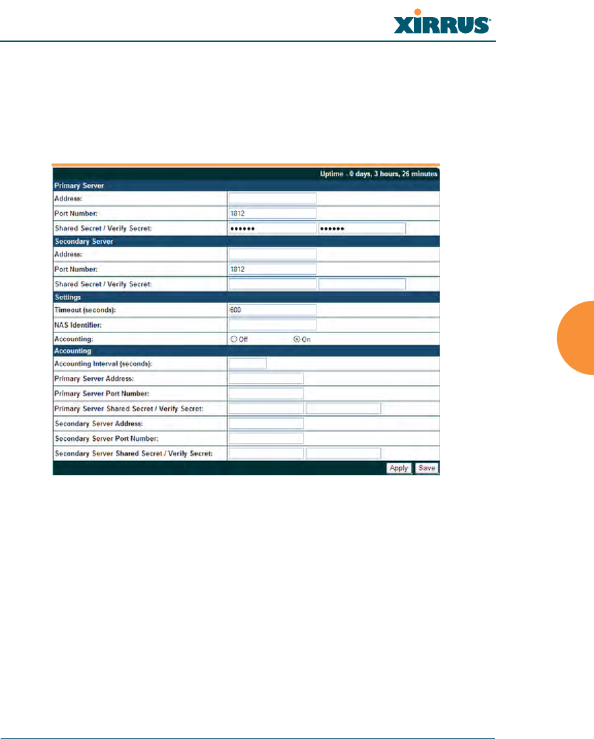
Figure 110. External RADIUS Server
If you want to include user group membership in the RADIUS account
information for users, see “Understanding Groups” on page 196. User groups
allow you to easily apply a uniform configuration to a user on the Array.
Procedure for Configuring an External RADIUS Server
1. Primary Server: This is the external RADIUS server that you intend to
use as your primary server.
a. Address: Enter the IP address of this external RADIUS server.

Wi-Fi Array
178 Configuring the Wi-Fi Array
b. Port Number: Enter the port number of this external RADIUS server.
The default is 1812.
c. Shared Secret / Verify Secret: Enter the shared secret that this
external RADIUS server will be using, then re-enter the shared secret
to verify that you typed it correctly.
2. Secondary Server (optional): If desired, enter an alternative external
RADIUS server. If the primary RADIUS server becomes off-line, the
Array will “failover” to the secondary RADIUS server (defined here).
a. Address: Enter the IP address of this external RADIUS server.
b. Port Number: Enter the port number of this external RADIUS server.
The default is 1812.
c. Shared Secret / Verify Secret: Enter the shared secret that this
external RADIUS server will be using, then re-enter the shared secret
to verify that you typed it correctly.
3. Settings: Define the session timeout, the NAS Identifier, and whether
accounting will be used.
a. Timeout (seconds): Define the maximum idle time (in seconds)
before the external RADIUS server’s session times out. The default is
600 seconds.
b. NAS Identifier: From the point of view of a RADIUS server, the
Array is a client, also called a network access server (NAS). Enter the
NAS Identifier (IP address) that the RADIUS servers expect the Array
to use—this is normally the IP address of the Array’s Gigabit1 port.
c. Accounting: If you would like the Array to send RADIUS Start, Stop,
and Interim records to a RADIUS accounting server, click the On
button and click Apply. The account settings appear, and must be
configured.
#The shared secret that you define must match the secret used by the
external RADIUS server.

Wi-Fi Array
Configuring the Wi-Fi Array 179
4. Accounting Settings:
a. Accounting Interval (seconds): Specify how often Interim records are
to be sent to the server. The default is 300 seconds.
b. Primary Server Address: Enter the IP address of the primary
RADIUS accounting server that you intend to use.
c. Primary Port Number: Enter the port number of the primary
RADIUS accounting server. The default is 1813.
d. Primary Shared Secret / Verify Secret: Enter the shared secret that
the primary RADIUS accounting server will be using, then re-enter
the shared secret to verify that you typed it correctly.
e. Secondary Server Address (optional): If desired, enter an IP address
for an alternative RADIUS accounting server. If the primary server
goes off-line, the Array will “failover” to this secondary server
(defined here).
f. Secondary Port Number: If using a secondary accounting server,
enter its port number. The default is 1813.
g. Secondary Shared Secret / Verify Secret: If using a secondary
accounting server, enter the shared secret that it will be using, then re-
enter the shared secret to verify that you typed it correctly.
5. Click on the Apply button to apply the new settings to this session, or
click Save to apply your changes and make them permanent.
See Also
Admin Management
Global Settings (IAP)
Internal Radius
Access Control List
Management Control
Security
Understanding Groups
Wi-Fi Array
180 Configuring the Wi-Fi Array
Internal Radius
This window allows you to define the parameters for the Array’s internal
RADIUS server for user authentication. However, the internal RADIUS server
will only authenticate wireless clients that want to associate to the Array. This can
be useful if an external RADIUS server is not available. To set up the internal
RADIUS server, you must choose Internal as the RADIUS server mode in Global
Settings. Refer to “Global Settings” on page 174.
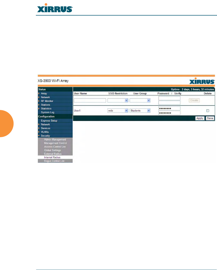
Figure 111. Internal RADIUS Server
Procedure for Creating a New User
1. User Name: Enter the name of the user that you want to authenticate to
the internal RADIUS server.
2. SSID Restriction: (Optional) If you want to restrict this user to
associating to a particular SSID, choose an SSID from the pull-down list.
3. User Group: (Optional) If you want to make this user a member of a
previously defined user group, choose a group from the pull-down list.
This will apply all of the user group’s settings to the user. See
“Understanding Groups” on page 196.
4. Password: (Optional) Enter a password for the user.

Wi-Fi Array
Configuring the Wi-Fi Array 181
5. Verify: (Optional) Retype the user password to verify that you typed it
correctly.
6. Click on the Create button to add the new user to the list.
Procedure for Managing Existing Users
1. SSID Restriction: (Optional) If you want to restrict a user to associating
to a particular SSID, choose an SSID from its pull-down list.
2. User Group: (Optional) If you want to change the user’s group, choose a
group from the pull-down list. This will apply all of the user group’s
settings to the user. See “Understanding Groups” on page 196.
3. Password: (Optional) Enter a new password for the selected user.
4. Verify Password: (Optional) Retype the user password to verify that you
typed it correctly.
5. If you want to delete one or more users, check their Delete check boxes,
then click Apply or Save.
6. Click on the Apply button to apply the new settings to this session, or
click Save to apply your changes and make them permanent.
See Also
Admin Management
External Radius
Global Settings (IAP)
Access Control List
Management Control
Security
Understanding Groups
Wi-Fi Array
182 Configuring the Wi-Fi Array
Rogue Control List
This window allows you to set up a control list for rogue APs, based on a type
that you define. You may classify rogue APs as blocked., so that the Array will
take steps to prevent stations from associating with the blocked AP. See “About
Blocking Rogue APs” on page 222. When finished, click on the Save button to
save your changes.
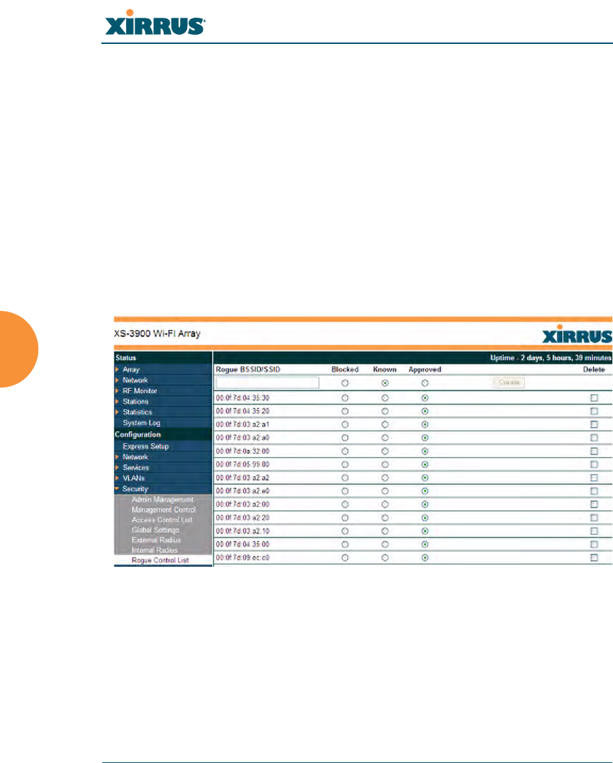
Figure 112. Rogue Control List
Procedure for Establishing Rogue AP Control
1. Rogue BSSID/SSID: Enter the BSSID or SSID for the new rogue AP.
2. Rogue Control Type: Define a type for the new rogue AP, either Blocked,
Known or Approved.
3. Click Create to add this rogue AP to the Rogue Control List.
#The RF Monitor > Intrusion Detection window provides an alternate
method for classifying rogues. You can list all Unknown stations and select
all the rogues that you’d like to set to Known or Approved, rather than
entering the SSID/BSSID as described below. See “Intrusion Detection” on
page 109.

Wi-Fi Array
Configuring the Wi-Fi Array 183
4. Rogue Control List: If you want to edit the control type for a rogue AP,
just click the radio button for the new type for the entry: Blocked, Known
or Approved, then click Apply or Save to apply your change.
5. To delete rogue APs from the list, click their Delete checkboxes, then click
Apply or Save.
6. Click Apply to apply the new settings to this session, or click Save to
apply your changes and make them permanent.
See Also
Network Map
Intrusion Detection
SSIDs
SSID Management
Wi-Fi Array
184 Configuring the Wi-Fi Array
SSIDs
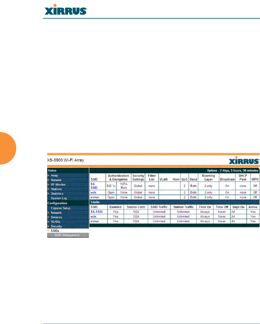
This is a status only window that allows you to review SSID (Service Set
IDentifier) assignments. It includes the SSID name, whether or not an SSID is
visible on the network, any security and QoS parameters defined for each SSID,
associated VLAN IDs, radio availability, and DHCP pools defined per SSID. You
may click on an SSID’s name to jump to the edit page for the SSID. There are no
configuration options available on this page, but if you are experiencing problems
or reviewing SSID management parameters, you may want to print this page for
your records.
For information to help you understand SSIDs and how multiple SSIDs are
managed by the Wi-Fi Array, go to “Understanding SSIDs” on page 185 and the
Multiple SSIDs section of “Frequently Asked Questions” on page 334. For a
description of how QoS operates on the Array, see “Understanding QoS Priority
on the Wi-Fi Array” on page 186.
Figure 113. SSIDs
The read-only Limits section of the SSIDs window allows you to review any
limitations associated with your defined SSIDs. For example, this window shows
the current state of an SSID (enabled or not), how much SSID and station traffic is
allowed, time on and time off, days on and off, and whether each SSID is
currently active or inactive.

Wi-Fi Array
Configuring the Wi-Fi Array 185
Understanding SSIDs
The SSID (Service Set Identifier) is a unique identifier that wireless networking
devices use to establish and maintain wireless connectivity. Multiple access points
on a network or sub-network can use the same SSIDs. SSIDs are case-sensitive
and can contain up to 32 alphanumeric characters (do not include spaces when
defining SSIDs).
Multiple SSIDs
A BSSID (Basic SSID) refers to an individual access point radio and its associated
clients. The identifier is the MAC address of the access point radio that forms the
BSS. A group of BSSs can be formed to allow stations in one BSS to communicate
to stations in another BSS via a backbone that interconnects each access point.
The Extended Service Set (ESS) refers to the group of BSSIDs that are grouped
together to form one ESS. The ESSID (often referred to as SSID or “wireless
network name”) identifies the Extended Service Set. Clients must associate to a
single ESS at any given time. Clients ignore traffic from other Extended Service
Sets that do not have the same SSID.
Legacy access points typically support one SSID per access point. Wi-Fi Arrays
support the ability to define and use multiple SSIDs simultaneously.
Using SSIDs
The creation of different wireless network names allows system administrators to
separate types of users with different requirements. The following policies can be
tied to an SSID:
zThe wireless security mode needed to join this SSID.
zThe wireless Quality of Service (QoS) desired for this SSID.
zThe wired VLAN associated with this SSID.
As an example, one SSID named accounting might require the highest level of
security, while another SSID named guests might have low security requirements.
Another example may define an SSID named voice that supports voice over
Wireless LAN phones with the highest Quality of Service (QoS) definition. This
SSID might also forward traffic to specific VLANs on the wired network.
Wi-Fi Array
186 Configuring the Wi-Fi Array
See Also
SSID Management
SSIDs
Understanding SSIDs
Understanding QoS Priority on the Wi-Fi Array
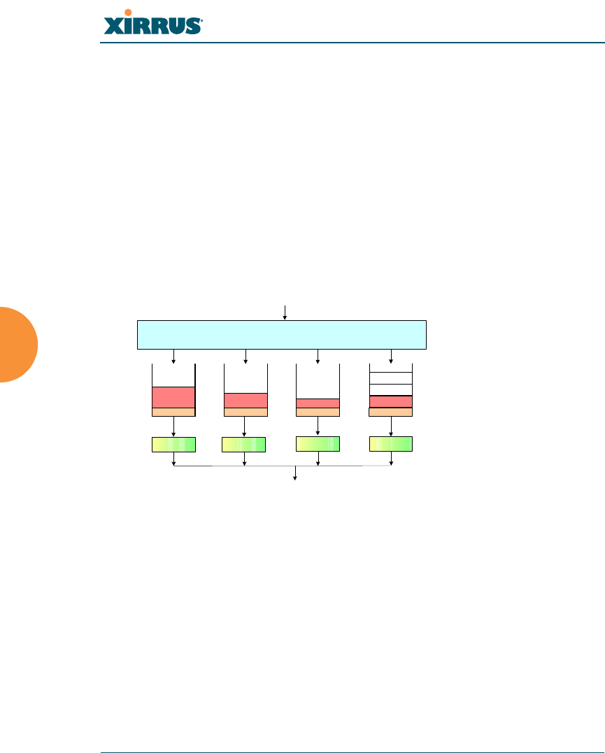
The Wi-Fi Array’s Quality of Service Priority feature (QoS) allows traffic to be
prioritized according to your requirements. For example, you typically assign the
highest priority to voice traffic, since this type of traffic requires delay to be under
10 ms. The Array has four separate queues for handling traffic at different
priorities, and thus it supports four traffic classes.
Figure 114. Four Traffic Classes
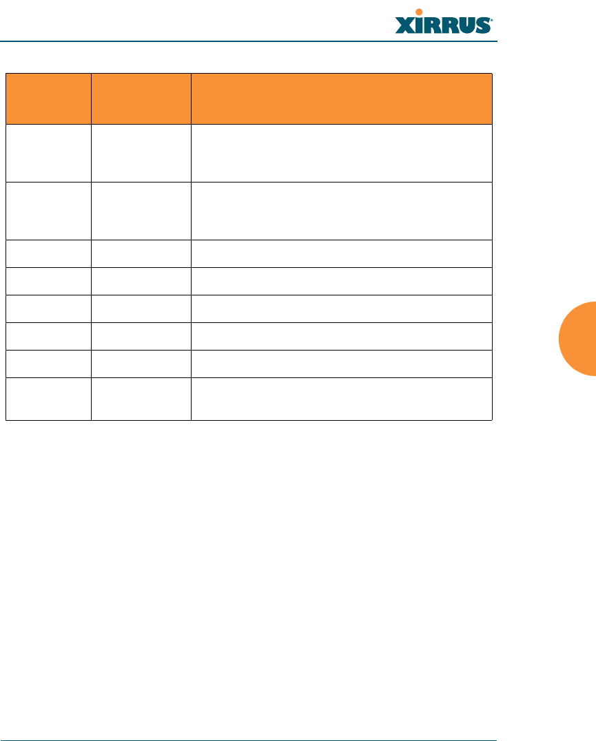
IEEE802.1p defines eight priority levels for wired networks. Each data packet
may be tagged with a priority level, i.e., a user priority tag. Since there are eight
possible user priority levels and the Array implements four traffic classes, user
priorities are mapped to traffic classes as shown in the table below. This table
follows the mapping recommended by IEEE802.1D, and its Annex G explains in
detail why this mapping was chosen.
Mapping to
Traffic Class
Four Transmit
Queues
Per queue channel access
Application Data
Voice
Data Video
Data Best Effort
Data Background
Data
IAP (Transmit)
Wi-Fi Array
Configuring the Wi-Fi Array 187
End-to-End QoS Handling
Wired QoS - Ethernet Port:
zEgress: Packets are IEEE802.1p tagged at the Ethernet port for upstream
traffic, thus enabling QoS at the edge of the network.
zIngress: Incoming packets are assigned QoS priority based on their SSID
and 802.1p tag (if any).
Wireless QoS - Radios:
zEach SSID can be assigned a separate QoS priority (i.e., traffic class) from
0 to 3, where 3 is highest priority and 0 is the default. See “SSID
Management” on page 189. If multiple SSIDs are used, packets from the
SSID with higher priority are transmitted first.
User
Priority Array Traffic
Class Typical Use
0 (Default) 1 Best Effort - For the default priority, we don’t
necessarily know anything about the type of
traffic. Thus, it is treated as best effort traffic.
10 (Lowest
priority) Background - Explicitly designated as low-
priority and non-delay sensitive, it is given the
lowest traffic class.
20Spare
31Excellent Effort
42Controlled Load
52Video
63Voice
7 (Highest
priority) 3 (Highest
priority) Network control
Wi-Fi Array
188 Configuring the Wi-Fi Array
zThe Array supports IEEE802.11e Wireless QoS for downstream traffic.
Higher priority packets wait a shorter time before gaining access to the
air and contend less with all other 802.11 devices on a channel.
Packet Filtering: QoS classification
zFilter rules can be used to redefine the QoS priority level to override
defaults. See “Filter Management” on page 235. This allows the QoS
priority level to be assigned based on protocol, source, or destination.
Voice Support:
zThe QoS priority implementation on the Array supports voice
applications, as certified by Spectralink’s Voice Interoperability for
Enterprise Wireless (VIEW) Certification Program. In particular,
Spectralink voice packets are automatically classified and prioritized.
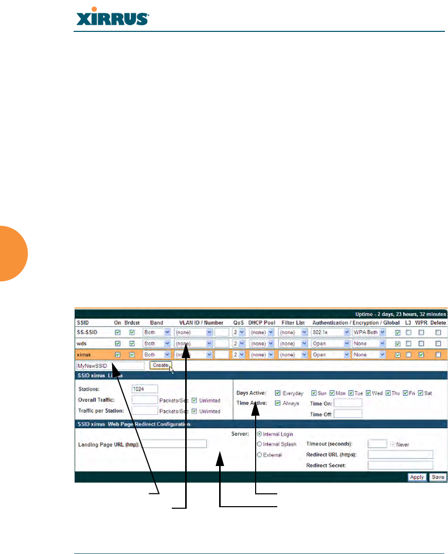
SSID Management
This window allows you to manage SSIDs (create, edit and delete), assign security
parameters and VLANs on a per SSID basis, and configure the Web Page Redirect
functionality. When finished, click on the Save button to save your changes.
Figure 115. SSID Management
Create new SSID
Configure parameters
Set traffic limits / usage schedule
Configure WPR

Wi-Fi Array
Configuring the Wi-Fi Array 189
Procedure for Managing SSIDs
1. New SSID Name: To create a new SSID, enter a new SSID name to the left
of the Create button (Figure 115), then click Create. You may create up to
16 SSIDs.
SSID List (top of page)
2. SSID: Shows all currently assigned SSIDs. When you create a new SSID,
the SSID name appears in this table. Click any SSID in this list to select it.
3. On: Check this box to activate this SSID or clear it to deactivate it.
4. Brdcast: Check this box to make the selected SSID visible to all clients on
the network. Although the Wi-Fi Array will not broadcast SSIDs that are
hidden, clients can still associate to a hidden SSID if they know the SSID
name to connect to it. Clear this box if you do not want this SSID to be
visible on the network.
5. Band: Choose which wireless band the SSID will be beaconed on. Select
either 5 GHz (802.11a/n), 2.4 GHz (802.11b/g/n) or Both.
6. VLAN ID / Number: From the pull-down list, select a VLAN that you
want this traffic to be forwarded to on the wired network. Select numeric
to enter the number of a previously defined VLAN in the Number field
(see “VLANs” on page 161). This step is optional.
7. QoS: (Optional) Select a value in this field for QoS (Quality of Service)
priority filtering. The QoS value must be one of the following:
•0—The lowest QoS priority setting, where QoS makes its best effort at
filtering and prioritizing data, video and voice traffic without
compromising the performance of the network. Use this setting in
environments where traffic prioritization is not a concern.
•1—Medium, with QoS prioritization aggregated across all traffic
types.
•2—High, normally used to give priority to video traffic.
•3—The highest QoS priority setting, normally used to give priority to
voice traffic.

Wi-Fi Array
190 Configuring the Wi-Fi Array
The QoS setting you define here will prioritize wireless traffic for this
SSID over other SSID traffic, as described in “Understanding QoS Priority
on the Wi-Fi Array” on page 186. The default value for this field is 2.
8. DHCP Pool: If you want to associate an internal DHCP pool to this SSID,
choose the pool from the pull--down list. An internal DHCP pool must be
created before it can be assigned. To create an internal DHCP pool, go to
“DHCP Server” on page 158.
9. Filter List: If you wish to apply a set a filters to this SSID’s traffic, select
the desired Filter List. See “Filters” on page 233.
10. Authentication: The following authentication options are available:
•Open: This option provides no authentication and is not
recommended.
•RADIUS MAC: Authenticates stations onto the Wi-Fi network via an
external RADIUS server based on the user’s MAC address.
•802.1x: Authenticates stations onto the Wi-Fi network via a RADIUS
server using 802.1x with EAP. The RADIUS server can be internal
(provided by the Wi-Fi Array) or external.
11. Encryption: From the pull-down list, choose the encryption that will be
required—specific to this SSID—either None, WEP, WPA, WPA2 or WPA-
Both. The None option provides no security and is not recommended;
WPA2 provides the best practice Wi-Fi security.
Each SSID supports only one encryption type at a time (except that WPA
and WPA2 are both supported on an SSID if you select WPA-Both). If you
need to support other encryption types, you must define additional
SSIDs. The encryption standard used with WPA or WPA2 is selected in
the Security>Global Settings window (page 174). For an overview of the
security options, see “Security Planning” on page 42 and “Understanding
Security” on page 165.
12. Global: Check the checkbox if you want this SSID to use the security
settings established at the global level (refer to “Global Settings” on
page 174). Clear the checkbox if you want the settings established here to

Wi-Fi Array
Configuring the Wi-Fi Array 191
take precedence. Additional sections will be displayed to allow you to
configure encryption settings, and RADIUS and RADIUS accounting
settings. The encryption settings are described in “Procedure for
Configuring Network Security” on page 175. The external RADIUS and
accounting settings are configured in the same way as for an external
RADIUS server (see “Procedure for Configuring an External RADIUS
Server” on page 177). Note that external RADIUS servers must be
specified using IP addresses rather than domain names.
13. L3: For this SSID, Check the checkbox to enable fast roaming between
IAPs or Arrays at Layer 2 and Layer 3, or clear the checkbox to allow
roaming at Layer 2 only. You may only select fast roaming at Layers 2 and
3 if this has been selected in Global Settings (IAP). See “Understanding
Fast Roaming” on page 203.
14. WPR (Web Page Redirect): Check the checkbox to enable the Web Page
Redirect functionality, or clear it to disable this option. If enabled, WPR
configuration fields will be displayed under the SSID Limits section. This
feature may be used to provide an alternate mode of authentication, or to
simply display a splash screen when a user first associates to the wireless
network. After that, it can (optionally) redirect the user to an alternate
URL. For example, some wireless devices and users may not have a
correctly configured 802.1x (RADIUS) supplicant. Utilizing WPR’s Web-
based login, users may be authenticated without using an 802.1x
supplicant. See “Web Page Redirect Configuration Settings” on page 193
for details of WPR usage and configuration.
SSID Limits
See “Group Limits” on page 200 for a discussion of the interaction of SSID limits
and group limits. To eliminate confusion, we recommend that you configure one
set of limits or the other, but not both.
15. Stations: Enter the maximum number of stations allowed on this SSID.
The default is 1024. This step is optional. Note that the IAPs - Global
Settings window also has a station limit option—Max Station

Wi-Fi Array
192 Configuring the Wi-Fi Array
Association per IAP. If both station limits are set, both will be enforced.
As soon as either limit is reached, no new stations can associate until
some other station has terminated its association.
16. Overall Traffic: Choose Unlimited if you do not want to place a
restriction on the traffic for this SSID, or enter a value in the Packets/Sec
field to force a traffic restriction.
17. Traffic per Station: Choose Unlimited if you do not want to place a
restriction on the traffic per station for this SSID, or enter a value in the
Packets/Sec field to force a traffic restriction.
18. Days Active: Choose Everyday if you want this SSID to be active every
day of the week, or select only the specific days that you want this SSID to
be active. Days that are not checked are considered to be the inactive
days.
19. Time Active: Choose Always if you want this SSID active without
interruption, or enter values in the Time On and Time Off fields to limit
the time that this SSID is active.
20. To delete SSIDs, click their Delete checkboxes, then click Apply or Save.
21. Click Apply to apply the changes to the selected SSID, or click Save to
apply your changes and make them permanent.
See Also
DHCP Server
External Radius
Global Settings (IAP)
Internal Radius
Security Planning
SSIDs
Understanding QoS Priority on the Wi-Fi Array
Wi-Fi Array
Configuring the Wi-Fi Array 193
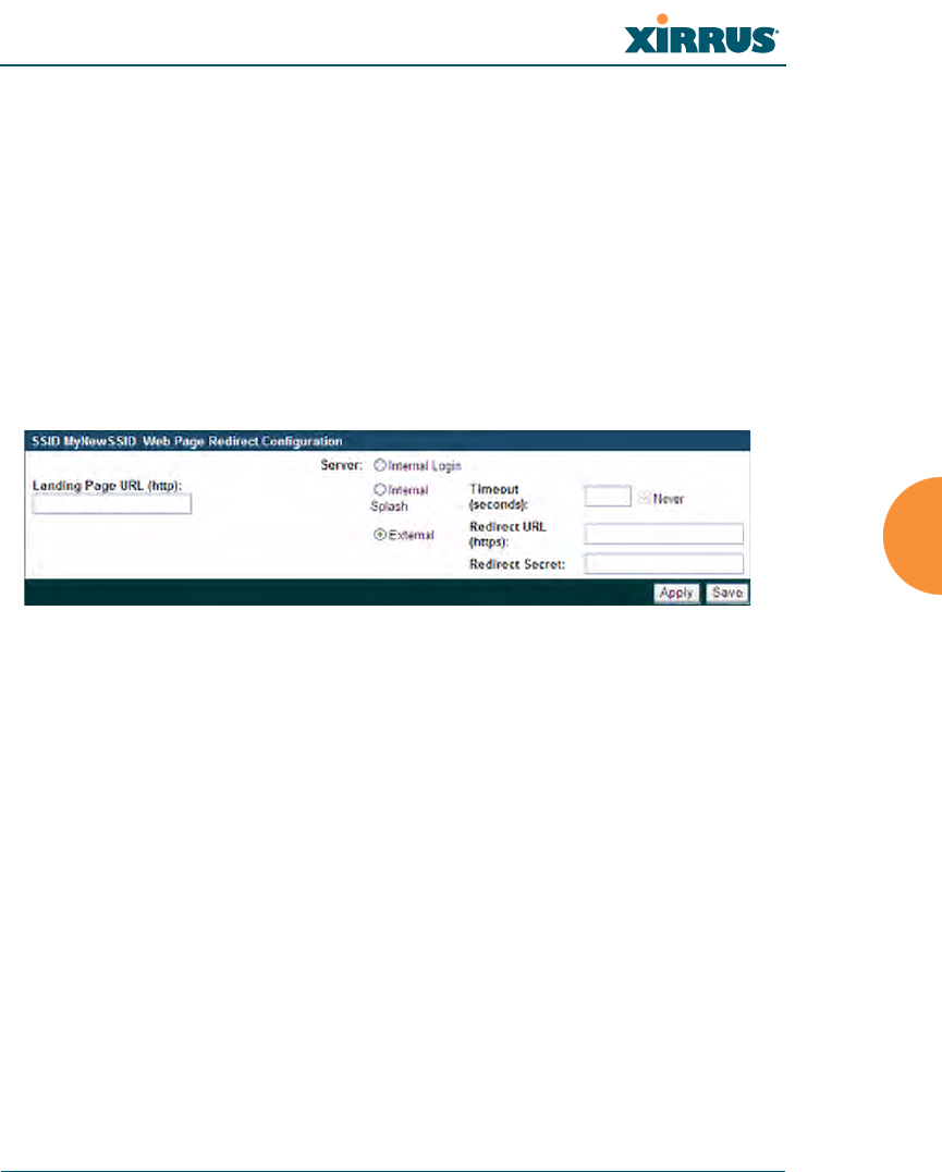
Web Page Redirect Configuration Settings
If you enable WPR, the SSID Management window displays additional fields that
must be configured. For example configurations and complete examples, please
check the Xirrus Customer Support web site: http://support.xirrus.com/.
If enabled, WPR displays a splash or login page when a user associates to the
wireless network and opens a browser to any URL (provided the URL does not
point to a resource directly on the user’s machine). The user-requested URL is
captured, the user’s browser is redirected to the splash or login page, and then the
browser is redirected either to your specified landing page, if any, or else back to
the captured URL.
Figure 116. WPR Internal Splash Page Fields (SSID Management)
You may select among three different modes for use of the Web Page Redirect
feature, each displaying a different set of parameters that must be entered:
zInternal Splash page
This option displays a splash page instead of the first user-requested
URL. The splash page files reside on the Array. Note that there is an
upload function that allows you to replace the default splash page, if you
wish. Please see “Web Page Redirect:” on page 244 for more information.
To set up use of a splash page, set Server to Internal Splash. Enter a value
in the Timeout field to define how many seconds the splash screen is
displayed before timing out, or select Never to prevent the page from
timing out automatically. After the splash page, the user is redirected to
the captured URL. If you want the user redirected to a specific landing
page instead, enter its address in Landing Page URL.

Wi-Fi Array
194 Configuring the Wi-Fi Array
zInternal Login page
This option displays a login page (residing on the Array) instead of the
first user-requested URL. Note that there is an upload function that
allows you to replace the default login page, if you wish. Please see “Web
Page Redirect:” on page 244 for more information.
To set up internal login, set Server to Internal Login.
The user name and password are obtained by the login page, and
authentication occurs according to your configured authentication
information (starting with Step 10 above). These parameters are
configured as described in “Procedure for Configuring Network
Security” on page 175.
After authentication, the browser is redirected back to the captured URL.
If you want the user redirected to a specific landing page instead, enter its
address in Landing Page URL.
zExternal Login page
This option redirects the user to a login page on an external web server
for authentication, instead of the first user-requested URL. Login
information (user name and password) must be obtained by that page,
and returned to the Array for authentication.
Authentication occurs according to your configured RADIUS
information. These parameters are configured as described in “Procedure
for Configuring Network Security” on page 175. After authentication, the
browser is redirected back to the captured URL. If you want the user
redirected to a specific landing page instead, enter its address in Landing
Page URL.
To set up external login page usage, set Server to External. Enter the URL
of the external web server in Redirect URL, and enter that server’s shared
secret in Redirect Password.
#Both the Internal Login and External Login options of WPR perform
authentication using your configured RADIUS servers.
Wi-Fi Array
Configuring the Wi-Fi Array 195
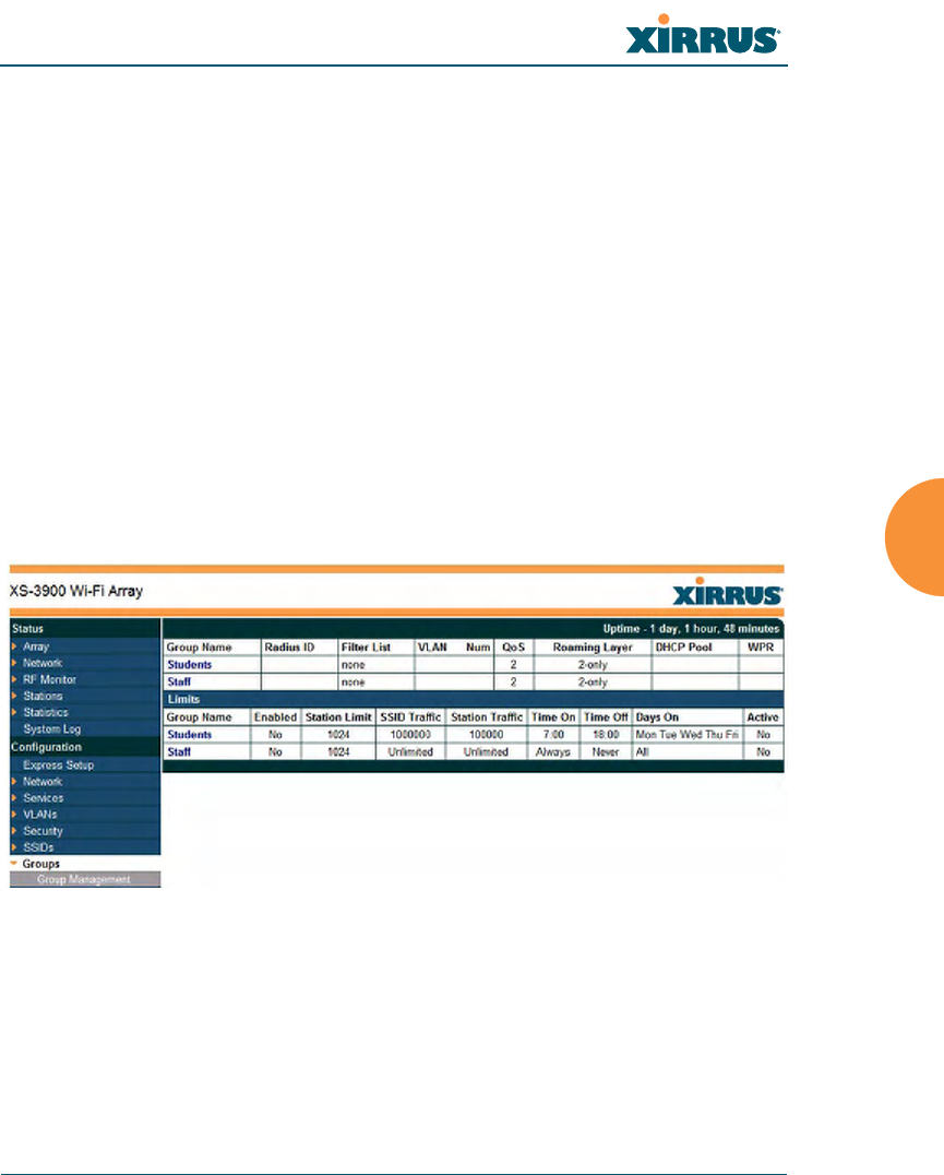
Groups
This is a status only window that allows you to review user Group assignments. It
includes the group name, Radius ID, VLAN IDs and QoS parameters and
roaming layer defined for each group, and DHCP pools and web page redirect
information defined for the group. You may click on a group’s name to jump to
the edit page for the group. There are no configuration options available on this
page, but if you are experiencing problems or reviewing group management
parameters, you may want to print this page for your records.
The Limits section of this window shows any limitations configured for your
defined groups. For example, this window shows the current state of a group
(enabled or disabled), how much group and per-station traffic is allowed, time on
and time off, and days on and off.
For information to help you understand groups, see Understanding Groups
below.
Figure 117. Groups
Understanding Groups
User groups allow administrators to assign specific network parameters to users
through RADIUS privileges rather than having to map users to a specific SSID.
Groups provide flexible control over user privileges without the need to create
large numbers of SSIDs.

Wi-Fi Array
196 Configuring the Wi-Fi Array
A group allows you to define a set of parameter values to be applied to selected
users. For example, you might define the user group Students, and set its VLAN,
security parameters, web page redirect (WPR), and traffic limits. When a new user
is created, you can apply all of these settings just by making the user a member of
the group. The group allows you to apply a uniform configuration to a set of users
in one step.
Almost all of the parameters that can be set for a group are the same as SSID
parameters. This allows you to configure features at the user group level, rather
than for an entire SSID. If you set parameter values for an SSID, and then enter
different values for the same parameters for a user group, the user group values
have priority (i.e., group settings will override SSID settings).
Group names are case-sensitive and can contain up to 32 alphanumeric characters
(do not include spaces when defining Groups).
Using Groups
User accounts are used to authenticate wireless clients that want to associate to
the Array. These accounts are established in one of two ways, using the Security>
Internal Radius window or the Security> External Radius window. In either
case, you may select a user group for the user, and that user group’s settings will
apply to the user:
zInternal Radius—when you add or modify a user entry, select a user
group to which the user will belong.
zExternal Radius—when you add or modify a user account, specify the
Radius ID for the user group to which the user will belong. This must be
the same Radius ID that was entered in the Group Management window.
When the user is authenticated, the external Radius server will send the
Radius ID to the Array. This will allow the Array to identify the group to
which the user belongs.
See Also
External Radius
Internal Radius
SSIDs
Wi-Fi Array
Configuring the Wi-Fi Array 197
Understanding QoS Priority on the Wi-Fi Array
Web Page Redirect Configuration Settings
Understanding Fast Roaming
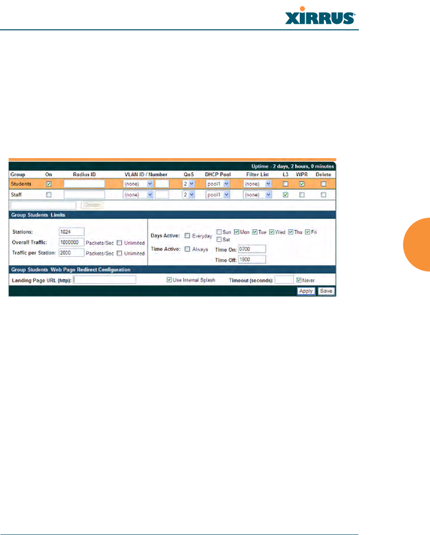
Group Management
This window allows you to manage groups (create, edit and delete), assign usage
limits and other parameters on a per group basis, and configure the Web Page
Redirect functionality. When finished, click the Save button to save your changes.
Figure 118. Group Management
Procedure for Managing Groups
1. New Group Name: To create a new group, enter a new group name next
to the Create button, then click Create. You may create up to 16 groups.
To configure and enable this group, proceed with the following steps.
2. Group: This column lists currently defined groups. When you create a
new group, the group name appears in this list. Click on any group to
select it, and then proceed to modify it as desired.
3. On: Check this box to enable this group or leave it blank to disable it.
When a group is disabled, users that are members of the group will
behave as if the group did not exist. In other words, the options
configured for the SSID will apply to the users, rather than the options
configured for the group.

Wi-Fi Array
198 Configuring the Wi-Fi Array
4. Radius ID: Enter a unique Radius ID for the group, to be used on an
external Radius server. When adding a user account to the external
server, this Radius ID value should be entered for the user. When the user
is authenticated, Radius sends this value to the Array. This tells the Array
that the user is a member of the group having this Radius ID.
5. VLAN ID: (Optional) From the pull-down list, select a VLAN for this
user’s traffic to use. Select numeric and enter the number of a previously
defined VLAN (see “VLANs” on page 161). This user group’s VLAN
settings supersede Dynamic VLAN settings (which are passed to the
Array by the Radius server). To avoid confusion, we recommend that you
avoid specifying the VLAN for a user in two places.
6. QoS Priority: (Optional) Select a value in this field for QoS (Quality of
Service) priority filtering. The QoS value must be one of the following:
•0—The lowest QoS priority setting, where QoS makes its best effort at
filtering and prioritizing data, video and voice traffic without
compromising the performance of the network. Use this setting in
environments where traffic prioritization is not a concern.
•1—Medium; QoS prioritization is aggregated across all traffic types.
•2—High, normally used to give priority to video traffic.
•3—The highest QoS priority setting, normally used to give priority to
voice traffic.
The QoS setting you define here will prioritize wireless traffic for this
group versus other traffic, as described in “Understanding QoS Priority
on the Wi-Fi Array” on page 186. The default value for this field is 2.
7. Internal DHCP Pool Assigned: (Optional) To associate an internal DHCP
pool to this group, select it from the pull--down list. Only one pool may
be assigned. An internal DHCP pool must be created before it can be
assigned. To create a DHCP pool, go to “DHCP Server” on page 158.
8. Filter List: (Optional) If you wish to apply a set a filters to this user
group’s traffic, select the desired Filter List. See “Filters” on page 233.

Wi-Fi Array
Configuring the Wi-Fi Array 199
9. L3: (Optional) For this group, check this box to enable fast roaming
between IAPs or Arrays at Layer 2 and Layer 3. If the box is not checked,
then roaming uses Layer 2 only. You may only select fast roaming at
Layers 2 and 3 if this has been selected in Global Settings (IAP). See
“Understanding Fast Roaming” on page 203.
10. WPR (Web Page Redirect): (Optional) Check this box if you wish to
enable the Web Page Redirect functionality. This will open a Web Page
Redirect details section in the window, where your WPR parameters may
be entered. This feature may be used to display a splash screen when a
user first associates to the wireless network. After that, it can (optionally)
redirect the user to an alternate URL. See “Web Page Redirect
Configuration Settings” on page 193 for details of WPR usage and
configuration. Note that the Group Management window only allows
you to set up and Internal Splash page. The authentication options that
are offered on the SSID Management page are not offered here. Since the
group membership of a user is provided to the Array by a Radius server,
this means the user has already been authenticated.
Group Limits
The Limits section allows you to limit the traffic or connection times allowed for
this user group. Note that the IAPs—Global Settings window and the SSID
management windows also have options to limit the number of stations, limit
traffic, and/or limit connection times. If limits are set in more than one place, all
limits will be enforced:
zAs soon as any station limit is reached, no new stations can associate until
some other station has terminated its association.
zAs soon as any traffic limit is reached, it is enforced.
zIf any connection date/time restriction applies, it is enforced.
You can picture this as a logical AND of all restrictions. For example, suppose that
a station’s SSID is available MTWTF between 8:00am and 5:00pm, and the User
Group is available MWF between 6:00am and 8:00pm, then the station will be
allowed on MWF between 8:00am and 5:00pm.

Wi-Fi Array
200 Configuring the Wi-Fi Array
To eliminate confusion, we recommend that you configure one set of limits or the
other, but not both.
11. Stations: Enter the maximum number of stations allowed on this group.
The default is 1024.
12. Overall Traffic: Check the Unlimited checkbox if you do not want to
place a restriction on the traffic for this group, or enter a value in the
Packets/Sec field and make sure that the Unlimited box is unchecked to
force a traffic restriction.
13. Traffic per Station: Check the Unlimited checkbox if you do not want to
place a restriction on the traffic per station for this group, or enter a value
in the Packets/Sec field and make sure that the Unlimited box is
unchecked to force a traffic restriction.
14. Days Active: Choose Everyday if you want this group to be active every
day of the week, or select only the specific days that you want this group
to be active. Days that are not checked are considered to be the inactive
days.
15. Time Active: Choose Always if you want this group active without
interruption, or enter values in the Time On and Time Off fields to limit
the time that group members may associate.
16. Click on the Apply button to apply the changes to the selected group, or
click Save to apply your changes and make them permanent.
17. To delete an entry, check its Delete checkbox, then click the Save button to
permanently remove the entry.
See Also
DHCP Server
External Radius
Internal Radius
Security Planning
SSIDs
Wi-Fi Array
Configuring the Wi-Fi Array 201
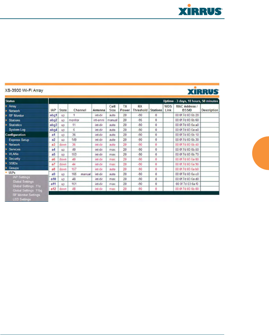
IAPs
This status-only window summarizes the status of the Integrated Access Points
(radios). For each IAP, it shows whether it is up or down, the channel and antenna
that it is currently using, its cell size and transmit and receive power, how many
users (stations) are currently associated to it, whether it is part of a WDS link, and
its MAC address.
Figure 119. IAPs
There are no configuration options in this window, but if you are experiencing
problems or simply reviewing the IAP assignments, you may print this window
for your records. Click any IAP name to open the associated configuration page.
Arrays have a fast roaming feature, allowing them to maintain sessions for
applications such as voice, even while users cross boundaries between Arrays.
Fast roaming is set up in the Global Settings (IAP) window and is discussed in:
z“Understanding Fast Roaming” on page 203
IAPs are configured using the following windows:
z“IAP Settings” on page 204
z“Global Settings (IAP)” on page 209

Wi-Fi Array
202 Configuring the Wi-Fi Array
z“Global Settings .11an” on page 214
z“Global Settings .11bgn” on page 217
z“Advanced RF Settings” on page 221
z“LED Settings” on page 227
See Also
IAP Statistics Summary
Understanding Fast Roaming
To maintain sessions for real-time data traffic, such as voice and video, users must
be able to maintain the same IP address through the entire session. With
traditional networks, if a user crosses VLAN or subnet boundaries (i.e., roaming
between domains), a new IP address must be obtained.
Mobile Wi-Fi users are likely to cross multiple roaming domains during a single
session (especially wireless users of VoIP phones). Layer 3 roaming allows a user
to maintain the same IP address through an entire real-time data session.
The Layer 3 session is maintained by establishing a tunnel back to the originating
Array. You should decide whether or not to use Layer 3 roaming based on your
wired network design. Layer 3 roaming incurs extra overhead and may result in
additional traffic delays.
Fast Roaming is configured on two pages. To enable the fast roaming options that
you want to make available on your Array, see Step 16 to Step 18 in “Global
Settings (IAP)” on page 209. To choose which of the enabled options are used by
an SSID or Group, see “Procedure for Managing SSIDs” on page 189 (Step 13) or
“Procedure for Managing Groups” on page 198.
Wi-Fi Array
Configuring the Wi-Fi Array 203
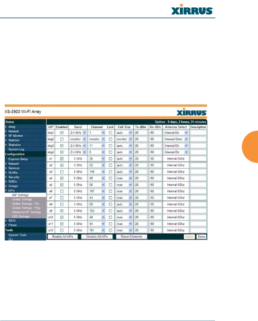
IAP Settings
This window allows you to enable/disable IAPs, define the wireless mode for
each IAP, specify the channel to be used and the cell size for each IAP, lock the
channel selection, establish transmit/receive parameters, select antennas, and
reset channels. Buttons at the bottom of the list allow you to Reset Channels,
Enable All IAPs, or Disable All IAPs. When finished, click on the Apply button
to apply the new settings to this session, or click Save to apply your changes and
make them permanent. To see a diagram of the layout and naming of IAPs, go to
Figure 6 on page 13.
Figure 120. IAP Settings

Wi-Fi Array
204 Configuring the Wi-Fi Array
Procedure for Auto Configuring IAPs
You can auto-configure channel and cell size of radios by clicking on the Auto
Configure buttons on the relevant WMI page (auto configuration only applies to
enabled radios):
zFor all radios, go to “Advanced RF Settings” on page 221.
zFor all 802.11an radios, go to “Global Settings .11an” on page 214.
zFor all 802.11bgn radios, go to “Global Settings .11bgn” on page 217.
Procedure for Manually Configuring IAPs
1. In the Enabled column, check the box for a corresponding IAP to enable
the IAP, or uncheck the box if you want to disable the IAP.
2. In the Band column for 802.11a/b/g/n radios, select the wireless band
for this IAP from the choices available in the pull-down menu, either
2.4GHz or 5 GHz. If the mode displayed is Auto, the mode has been set
by the auto-channel feature based on the Channel selected. Note that IAP
abg2 has an additional option—monitor mode. IAP abg2 should
normally be set to monitor mode to enable Spectrum Analyzer and radio
assurance (loopback testing) features.
3. In the Channel column, select the channel you want this IAP to use from
the channels available in the pull-down list. The list shows the channels
available for the IAP selected (depending on which band the IAP is
using). Channels that are shown in color indicate conditions that you
need to keep in mind:
•RED—Usage is not recommended, for example, because of overlap
with neighboring radios.
•YELLOW—The channel has less than optimum separation (some
degree of overlap with neighboring radios).
#The XN16 allows up to 12 IAPs to operate as 5 GHz (802.11a/n) radios
concurrently. Do not set Mode to 5 GHz for more than 12 IAPs. If you need
additional 5 GHz radios, please contact Xirrus Customer Support. See
“Contact Information” on page 349.

Wi-Fi Array
Configuring the Wi-Fi Array 205
•GRAY—The channel is already in use.
Select Auto to have the Array dynamically select a channel automatically,
based on changes in the Wi-Fi environment. See “Allocating Channels”
on page 36. After you click Apply, this window and the IAPs window
will show the channel that was assigned, rather than Auto.
The channels that are available for assignment to an IAP will differ,
depending on the country of operation. If Country is set to United States
in the Global Settings (IAP) window, then 24 channels are available to
802.11an radios.
If you have enabled Public Safety in the Advanced RF Settings window
(Step 18), then the public safety band channels (191 and 195) in the
4.9GHz spectrum range will be listed. Operating these channels requires
a license—using these channels without a license violates FCC rules.
Warning notices are displayed when you select these channels.
Click the Lock check box if you want to lock in your channel selection so
that the autochannel operation (see Advanced RF Settings) cannot change
it.
4. In the Cell Size column, select Auto to allow the optimal cell size to be
automatically computed (see “Fine Tuning Cell Sizes” on page 35). To set
the cell size yourself, choose either Small, Medium, Large, or Max to use
the desired pre-configured cell size, or choose Manual to define the
wireless cell size manually. If you choose Manual, you must specify the
transmit and receive power—in dB—in the Tx dBm (transmit) and Rx
dBm (receive) fields. The default is Max.
When other Arrays are within listening range of this one, setting cell sizes
to Auto allows the Array to change cell sizes so that coverage between
cells is maintained. Each cell size is optimized to limit interference
between sectors of other Arrays on the same channel. This eliminates the
#As mandated by FCC law, Arrays continually scan for signatures of military
radar. If such a signature is detected, the Array will switch operation from
conflicting channels to new ones.
Wi-Fi Array
206 Configuring the Wi-Fi Array
need for a network administrator to manually tune the size of each cell
when installing multiple Arrays. In the event that an Array or a radio
goes offline, an adjacent Array can increase its cell size to help
compensate.
The number of users and their applications are major drivers of
bandwidth requirements. The network architect must account for the
number of users within the Array’s cell diameter. In a large office, or if
multiple Arrays are in use, you may choose Small cells to achieve a
higher data rate, since walls and other objects will not define the cells
naturally.
For additional information about cell sizes, go to “Coverage and Capacity
Planning” on page 32.
5. In the Antenna Select column, choose the antenna you want this radio to
use from the pull-down list. The list of available antennas will be different
(or no choices will be available), depending on the wireless mode you
selected for the IAP.
6. If desired, enter a description for this IAP in the Description field.
7. You may reset all of the enabled IAPs by clicking the Reset Channels
button at the bottom of the list. A message will inform you that all
enabled radios have been taken down and brought back up.
8. Buttons at the bottom of the list allow you to Enable All IAPs or Disable
All IAPs.

Wi-Fi Array
Configuring the Wi-Fi Array 207
9. Click on the Apply button to apply the new settings to this session, or
click Save to apply your changes and make them permanent.
See Also
Coverage and Capacity Planning
Global Settings (IAP)
Global Settings .11an
Global Settings .11bgn
IAPs
IAP Statistics Summary
LED Settings
Wi-Fi Array
208 Configuring the Wi-Fi Array
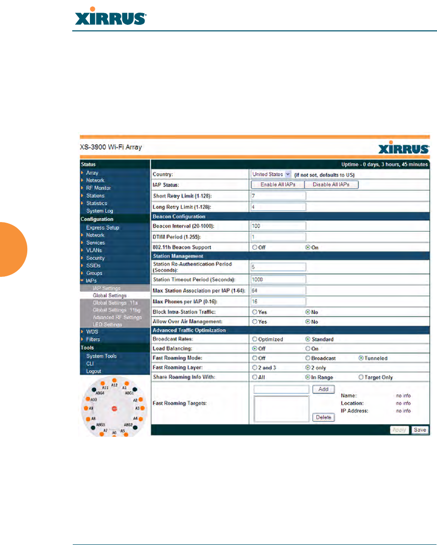
Global Settings (IAP)
This window allows you to establish global IAP settings. Global IAP settings
include enabling or disabling all IAPs (regardless of their operating mode),
enabling or disabling the Beacon World Mode, specifying the short and long retry
limits, and defining the beacon interval and DTIM period. Changes you make on
this page are applied to all IAPs, without exception.
Figure 121. Global Settings (IAPs)
Procedure for Configuring Global IAP Settings
1. Country: If no country is set, you may choose from the pull-down list.
Once a country has been chosen, it may not be changed. You are
responsible for choosing the correct country and conforming to the

Wi-Fi Array
Configuring the Wi-Fi Array 209
regulatory laws for wireless transmissions within your country. Please
contact Xirrus Customer Support if you need to change the operating
country after a country has already been set (see “Contact Information”
on page 349).
The channels that are available for assignment to an IAP will differ,
depending on the country of operation. If you set Country to United
States, then 24 channels are available to 802.11an radios.
Until you have chosen a country, the channel set defaults to channels and
power levels that are legal worldwide—this set only includes the lower
eight 5 GHz channels.
2. IAP Status: Click on the Enable All IAPs button to enable all IAPs for
this Array, or click on the Disable All IAPs button to disable all IAPs.
3. Short Retry Limit: This attribute indicates the maximum number of
transmission attempts for a frame, the length of which is less than or
equal to the RTS Threshold, before a failure condition is indicated. The
default value is 7. Enter a new value (1 to 128) in the Short Retry Limit
field if you want to increase or decrease this attribute.
4. Long Retry Limit: This attribute indicates the maximum number of
transmission attempts for a frame, the length of which is greater than the
RTS Threshold, before a failure condition is indicated. The default value
is 4. Enter a new value (1 to 128) in the Long Retry Limit field if you want
to increase or decrease this attribute.
Beacon Configuration
5. Beacon Interval: When the Array sends a beacon, it includes with it a
beacon interval, which specifies the period of time before it will send the
beacon again. Enter the desired value in the Beacon Interval field,
between 20 and 1000. The value you enter here is applied to all IAPs.
6. DTIM Period: A DTIM (Delivery Traffic Indication Message) is a signal
sent as part of a beacon by the Array to a client device in sleep mode,
alerting the device to broadcast traffic awaiting delivery. The DTIM
Period is a multiple of the Beacon Interval, and it determines how often

Wi-Fi Array
210 Configuring the Wi-Fi Array
DTIMs are sent out. By default, the DTIM period is 1, which means that it
is the same as the beacon interval. Enter the desired multiple, between 1
and 255. The value you enter here is applied to all IAPs.
7. 802.11h Beacon Support: This option enables beacons on all of the
Array’s radios to conform to 802.11h requirements, supporting dynamic
frequency selection (DFS) and transmit power control (TPC) to satisfy
regulatory requirements for operation in Europe.
Station Management
8. Station Re-Authentication Period: This option allows you to specify a
time (in seconds) for the duration of station reauthentications.
9. Station Timeout Period: Specify a time (in seconds) in this field to define
the timeout period for station associations.
10. Max Station Association per IAP: This option allows you to define how
many station associations are allowed per IAP (up to 64 stations per IAP).
Note that the SSIDs —SSID Management window also has a station limit
option— Station Limit (page 192). If both station limits are set, both will
be enforced. As soon as either limit is reached, no new stations can
associate until some other station has terminated its association.
11. Max Phones per IAP: This option allows you to control the maximum
number of phones that are allowed per IAP. The default is set to a
maximum of 16 but you can reduce this number, as desired. Enter a value
in this field between 0 (no phones allowed) and 16.
12. Block Intra-Station Traffic: This option allows you to block or allow
traffic between wireless clients that are associated to the Array. Choose
either Yes (to block traffic) or No (to allow traffic).
13. Allow Over Air Management: Choose Yes to enable management of the
Array via the IAPs, or choose No (recommended) to disable this feature.
#This admission control feature applies only to Spectralink phones. It does not
apply to all VoIP phones in general.

Wi-Fi Array
Configuring the Wi-Fi Array 211
Advanced Traffic Optimization
14. Broadcast Rates: This option changes the rates of broadcast traffic sent by
the Array (including beacons). When set to Optimized, each IAP
broadcasts at the lowest Array TX data rate currently in use by associated
stations, thus improving system performance. For example, if ten stations
are associated at 54Mbps and one station at 12Mbps, broadcasts will go
out at 12Mbps. One out of eight beacons are sent out at the lowest basic
rate (1 Mbps for 802.11bgn radios, 6Mbps for 802.11an radios).
When set to Standard (the default), broadcasts are sent out at the lowest
basic rate only. The option you select here is applied to all IAPs.
15. Load Balancing: This option enables or disables active load balancing
between the Array IAPs. Choose On to enable load balancing, or choose
Off to disable load balancing.
16. Fast Roaming Mode: This feature utilizes the Xirrus Roaming Protocol
(XRP) ensuring fast and seamless roaming capabilities between IAPs or
Arrays at Layer 2 and Layer 3 (as specified in Step 17), while maintaining
security. Fast roaming eliminates long delays for re-authentication, thus
supporting time-sensitive applications such as Voice over Wi-Fi (see
“Understanding Fast Roaming” on page 203 for a discussion of this
feature). XRP uses a discovery process to identify other Xirrus Arrays as
fast roaming targets. This process has two modes:
•Broadcast—the Array uses a broadcast technique to discover other
Arrays that may be targets for fast roaming.
•Tunneled—in this Layer 3 technique, fast roaming target Arrays
must be explicitly specified.
To enable fast roaming, choose Broadcast or Tu n n e l ed , and set additional
fast roaming attributes (Step 18). To disable fast roaming, choose Off. If
you enable Fast Roaming, the following ports cannot be blocked:
•Port 22610—reserved for Layer 2 roaming using UDP to share PMK
information between Arrays.
•Ports 15000 to 17999—reserved for Layer 3 roaming (tunneling
between subnets).

Wi-Fi Array
212 Configuring the Wi-Fi Array
17. Fast Roaming Layer: Select whether to enable roaming capabilities
between IAPs or Arrays at Layer 2 and 3, or at Layer 2 only. Depending
on your wired network, you may wish to allow fast roaming at Layer 3.
This may result in delayed traffic.
18. Share Roaming Info With: Three options allow your Array to share
roaming information with all Arrays; just with those that are within
range; or with specifically targeted Arrays. Choose either All, In Range
or Targe t O nly, respectively.
a. Fast Roaming Targets: If you chose Target On ly, use this option to
add target MAC addresses. Enter the MAC address of each target
Array, then click on Add (add as many targets as you like). To find a
target’s MAC address, open the Array Info window on the target
Array and look for IAP MAC Range, then use the starting address of
this range.
To delete a target, select it from the list, then click Delete.
19. Click on the Apply button to apply the new settings to this session, or
click Save to apply your changes and make them permanent.
See Also
Coverage and Capacity Planning
Global Settings .11an
Global Settings .11bgn
Advanced RF Settings
IAPs
IAP Statistics Summary
LED Settings
IAP Settings
Wi-Fi Array
Configuring the Wi-Fi Array 213
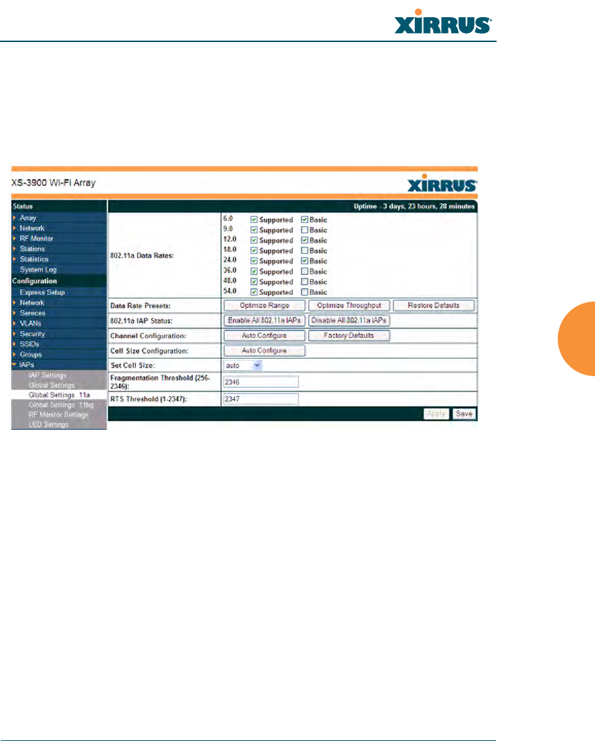
Global Settings .11an
This window allows you to establish global 802.11an IAP settings. These settings
include defining which 802.11an data rates are supported, enabling or disabling
all 802.11an IAPs, auto-configuration of channel allocations for all 802.11an IAPs,
and specifying the fragmentation and RTS thresholds for all 802.11an IAPs.
Figure 122. Global Settings .11an
Procedure for Configuring Global 802.11an IAP Settings
1. 802.11an Data Rates: The Array allows you to define which data rates are
supported for all 802.11an radios. Select (or deselect) data rates by
clicking in the corresponding Supported and Basic data rate check boxes.
•Basic Rate—a wireless station (client) must support this rate in
order to associate.
•Supported Rate—the Array will use this data rate for
transmissions to clients.
2. Data Rate Presets: The Wi-Fi Array can optimize your 802.11an data rates
automatically, based on range or throughput. Click on the Optimize
Range button to optimize data rates based on range, or click on the

Wi-Fi Array
214 Configuring the Wi-Fi Array
Optimize Throughput button to optimize data rates based on
throughput. The Restore Defaults button will take you back to the
factory default rate settings.
3. 802.11an IAP Status: Click Enable 802.11an IAPs to enable all 802.11an
IAPs for this Array, or click Disable 802.11an IAPs to disable all 802.11an
IAPs.
4. Channel Configuration: Click Auto Configure to instruct the Array to
determine the best channel allocation settings for each 802.11an IAP and
select the channel automatically, based on changes in the environment.
This is the recommended method for 802.11an channel allocations. Use
the Factory Defaults button to take you back to the factory default
channel settings.
5. Cell Size Configuration: Click Auto Configure to instruct the Array to
determine and set the best cell size for each enabled 802.11an IAP, based
on changes in the environment. This is the recommended method for
setting cell size. On the IAP Settings window, each enabled 802.11an IAP
will have its cell size set to auto.
6. Set Cell Size: The Cell Size may be set globally for all 802.11an IAPs to
auto, large, medium, small, or max using the drop down menu.
7. Fragmentation Threshold: This is the maximum size for directed data
packets transmitted over the 802.11an radio. Larger frames fragment into
several packets, their maximum size defined by the value you enter here.
Smaller fragmentation numbers can help to “squeeze” packets through in
noisy environments. Enter the desired Fragmentation Threshold value in
this field, between 256 and 2346.
8. RTS Threshold: The RTS (Request To Send) Threshold specifies the
packet size. Packets larger than the RTS threshold will use CTS/RTS prior
to transmitting the packet—useful for larger packets to help ensure the
success of their transmission. Enter a value between 1 and 2347.
9. Click on the Apply button to apply the new settings to this session, or
click Save to apply your changes and make them permanent.

Wi-Fi Array
Configuring the Wi-Fi Array 215
See Also
Coverage and Capacity Planning
Global Settings (IAP)
Global Settings .11bgn
IAPs
IAP Statistics Summary
Advanced RF Settings
IAP Settings
Wi-Fi Array
216 Configuring the Wi-Fi Array
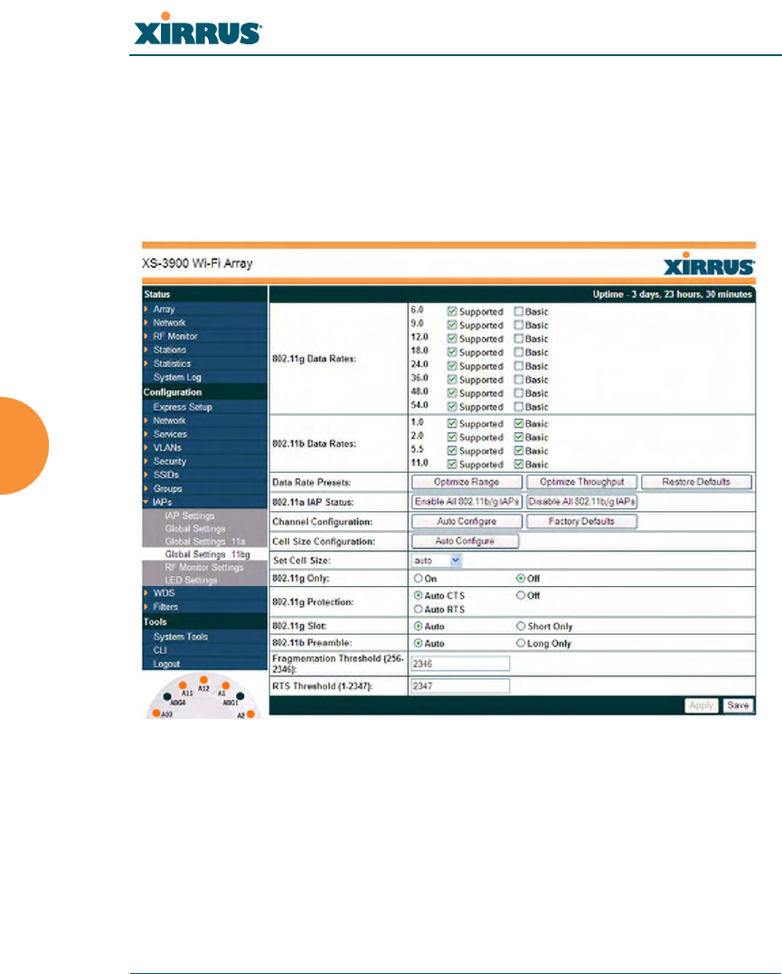
Global Settings .11bgn
This window allows you to establish global 802.11b/g/n IAP settings. These
settings include defining which 802.11b, 802.11g, and 802.11n data rates are
supported, enabling or disabling all 802.11b/g/n IAPs, auto-configuring 802.11b/
g/n IAP channel allocations, and specifying the fragmentation and RTS
thresholds for all 802.11b/g/n IAPs.
Figure 123. Global Settings .11bgn
Procedure for Configuring Global 802.11b/g/n IAP Settings
1. 802.11g Data Rates: The Array allows you to define which data rates are
supported for all 802.11g radios. Select (or deselect) 11g data rates by
clicking in the corresponding Supported and Basic data rate check boxes.
•Basic Rate—a wireless station (client) must support this rate in
order to associate.

Wi-Fi Array
Configuring the Wi-Fi Array 217
•Supported Rate—data rate used to transmit to clients.
2. 802.11b Data Rates: This task is similar to Step 1, but these data rates
apply only to 802.11b IAPs.
3. Data Rate Presets: The Wi-Fi Array can optimize your 802.11b/g/n data
rates automatically, based on range or throughput. Click Optimize Range
button to optimize data rates based on range, or click on the Optimize
Throughput to optimize data rates based on throughput. Restore
Defaults will take you back to the factory default rate settings.
4. 802.11b/g/n IAP Status: Click Enable All 802.11b/g/n IAPs to enable all
802.11b/g/n IAPs for this Array, or click Disable All 802.11b/g/n IAPs to
disable them.
5. Channel Configuration: Click Auto Configure to instruct the Array to
determine the best channel allocation settings for each 802.11b/g/n IAP
and select the channel automatically, based on changes in the
environment. This is the recommended method for 802.11b/g/n channel
allocations. Factory Defaults will take you back to the factory default
channel settings.
6. Cell Size Configuration: Click Auto Configure to instruct the Array to
determine and set the best cell size for each enabled 802.11b/g/n IAP,
based on changes in the environment. This is the recommended method
for setting cell size. On the IAP Settings window, the cell size of each
enabled 802.11b/g/n IAP will be set to auto.
7. Set Cell Size: The Cell Size may be set globally for all 802.11bgn IAPs to
auto, large, medium, small, or max using the drop down menu.
8. 802.11g Only: Choose On to restrict use to 802.11g mode only. In this
mode, no 802.11b rates are transmitted. Stations that only support 802.11b
will not be able to associate.
9. 802.11g Protection: You should select Auto CTS or Auto RTS to provide
automatic protection for all 802.11g radios in mixed networks (802.11
b and g). You may select Off to disable this feature, but this is not
recommended. Protection allows 802.11g stations to share an IAP with

Wi-Fi Array
218 Configuring the Wi-Fi Array
older, slower 802.11b stations. Protection avoids collisions by preventing
802.11b and 802.11g stations from transmitting simultaneously. When
Auto CTS or Auto RTS is enabled and any 802.11b station is associated to
the IAP, additional frames are sent to gain access to the wireless network.
•Auto CTS requires 802.11g stations to send a slow Clear To Send
frame that locks out other stations. Automatic protection reduces
802.11g throughput when 802.11b stations are present—Auto CTS
adds less overhead than Auto RTS. The default value is Auto CTS.
•With Auto RTS, 802.11g stations reserve the wireless media using a
Request To Send/Clear To Send cycle. This mode is useful when you
have dispersed nodes. It was originally used in 802.11b only
networks to avoid collisions from “hidden nodes”—nodes that are so
widely dispersed that they can hear the Array, but not each other.
When there are no 11b stations associated and an auto-protection mode is
enabled, the Array will not send the extra frames, thus avoiding
unnecessary overhead.
10. 802.11g Slot: Choose Auto to instruct the Array to manage the 802.11g
slot times automatically, or choose Short Only. Xirrus recommends using
Auto for this setting, especially if 802.11b devices are present.
11. 802.11b Preamble: The preamble contains information that the Array and
client devices need when sending and receiving packets. All compliant
802.11b systems have to support the long preamble. A short preamble
improves the efficiency of a network's throughput when transmitting
special data, such as voice, VoIP (Voice-over IP) and streaming video.
Select Auto to instruct the Array to manage the preamble (long and short)
automatically, or choose Long Only.
12. Fragmentation Threshold: This is the maximum size for directed data
packets transmitted over the 802.11b/g/n IAP. Larger frames fragment
into several packets, their maximum size defined by the value you enter
here. Enter the desired Fragmentation Threshold value, between 256 and
2346.

Wi-Fi Array
Configuring the Wi-Fi Array 219
13. RTS Threshold: The RTS (Request To Send) Threshold specifies the
packet size. Packets larger than the RTS threshold will use CTS/RTS prior
to transmitting the packet—useful for larger packets to help ensure the
success of their transmission. Enter a value between 1 and 2347.
14. Click on the Apply button to apply the new settings to this session, or
click Save to apply your changes and make them permanent.
See Also
Coverage and Capacity Planning
Global Settings (IAP)
Global Settings .11an
Advanced RF Settings
LED Settings
IAP Settings
IAP Statistics Summary
Wi-Fi Array
220 Configuring the Wi-Fi Array
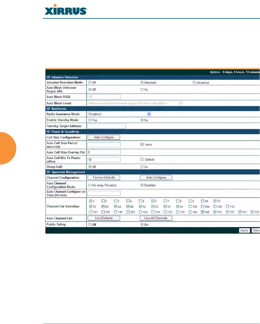
Advanced RF Settings
This window allows you to establish RF settings, including automatically
configuring channel allocation and cell size, specifying intrusion detection and
blocking of rogue APs, and configuring radio assurance and standby modes.
Changes you make on this page are applied to all IAPs, without exception.
Figure 124. Advanced RF Settings
About Standby Mode
Standby Mode supports the Array-to-Array fail-over capability. When you enable
Standby Mode, the Array functions as a backup unit, and it enables its radios if it
detects that its designated target Array has failed. The use of redundant Arrays to
provide this fail-over capability allows Arrays to be used in mission-critical
applications. In Standby Mode, an Array monitors beacons from the target Array.
When the target has not been heard from for 40 seconds, the standby Array

Wi-Fi Array
Configuring the Wi-Fi Array 221
enables its radios until it detects that the target Array has come back online.
Standby Mode is off by default. Note that you must ensure that the configuration
of the standby Array is correct. This window allows you to enable or disable
Standby Mode and specify the primary Array that is the target of the backup unit.
See also, “Failover Planning” on page 40.
About Blocking Rogue APs
If you classify a rogue AP as blocked (see “Rogue Control List” on page 182), then
the Array will take measures to prevent stations from staying associated to the
rogue. When the monitor radio abg2 is scanning, any time it hears a beacon from
a blocked rogue abg2 sends out a broadcast “deauth” signal using the rogue's
BSSID and source address. This has the effect of tossing off all of a rogue AP’s
clients approximately every 5 to 10 seconds, which is enough to make the rogue
frustratingly unusable.
The Advanced RF Settings window allows you to set up Auto Block parameters
so that unknown APs get the same treatment as explicitly blocked APs. This is
basically a "shoot first and ask questions later" mode. By default auto blocking is
turned off. Auto blocking provides two parameters for qualifying blocking so
that APs must meet certain criteria before being blocked. This keeps the Array
from blocking every AP that it detects. You may:
zSet a minimum RSSI value for the AP—for example, if an AP has an RSSI
value of -90, it is probably a harmless AP belonging to a neighbor and not
in your building.
zBlock based on encryption level.
Procedure for Configuring Advanced RF Settings
RF Intrusion Detection
1. Intrusion Detection: This option allows you to establish the intrusion
detection method, either Standard or Advanced, or you can choose Off to
disable this feature. See “Array Monitor and Loopback Testing
Capabilities” on page 341 for more information.

Wi-Fi Array
222 Configuring the Wi-Fi Array
•Standard—enables the abg2 radio as a monitor which collects Rogue
AP information.
•Advanced—this option works in conjunction with the Xirrus Defense
Module intrusion detection software (XDM). In this mode, the built-
in monitor radio (IAP abg2) functions as an RF threat sensor. Self-
monitoring is not enabled.
•Off—IAP abg2 does not function as a monitor.
2. Auto Block Unknown Rogue APs: Enable or disable auto blocking (see
“About Blocking Rogue APs” on page 222). If auto blocking is On, you
may set Auto Block RSSI and Auto Block Level.
3. Auto Block RSSI: Set the minimum RSSI for rogue APs to be blocked.
APs with lower RSSI values will not be blocked. They are assumed to be
farther away, and probably belonging to neighbors and posing a minimal
threat.
4. Auto Block Level: Select rogue APs to block based on the level of
encryption that they are using.
RF Resilience
5. Radio Assurance Mode: When this mode is enabled, IAP abg2 performs
loopback tests on the Array. This mode requires Intrusion Detection to be
set to Standard (Step 1) to enable abg2’s self-monitoring functions. It also
requires abg2 to be set to monitoring mode (see “Enabling Monitoring on
the Array” on page 341).
Operation of Radio Assurance mode (also called loopback mode) is
described in detail in “Array Monitor and Loopback Testing Capabilities”
on page 341.
The Radio Assurance mode scans and sends out probe requests on each
channel, in turn. It listens for all probe responses and beacons. These tests
are performed continuously (24/7). If no beacons or probe responses are
observed from a radio for a predetermined period, Radio Assurance
mode will take action according to the preference that you have specified:

Wi-Fi Array
Configuring the Wi-Fi Array 223
•Failure alerts only—The Array will issue alerts in the Syslog, but will
not initiate repairs or reboots.
•Failure alerts & repairs, but no reboots—The Array will issue alerts
and perform resets of one or all of the radios if needed.
•Failure alerts & repairs & reboots if needed—The Array will issue
alerts, perform resets, and schedule reboots if needed.
•Disabled—Disable IAP loopback tests (no self-monitoring occurs).
Loopback tests are disabled by default.
6. Enable Standby Mode: Choose Yes to enable this Array to function as a
backup unit for the target Array, or choose No to disable this feature. See
“About Standby Mode” on page 221.
7. Standby Target Address: If you enabled the Standby Mode, enter the
MAC address of the target Array (i.e., the address of the primary Array
that is being monitored and backed up by this Array). To find this MAC
address, open the Array Info window on the target Array, and use the
Gigabit1 MAC Address.
RF Power & Sensitivity
8. Cell Size Configuration: Click on the Auto Configure button to instruct
the Array to determine and set the best cell size for each enabled IAP,
based on changes in the environment. This is the recommended method
for setting cell size. On the IAP settings window, each enabled IAP will
have its cell size set to Auto.
9. Auto Cell Size Period: You may set up auto-configuration to run
periodically, readjusting optimal cell sizes for the current conditions.
Enter a number of seconds to specify how often auto-configuration will
run. If you select None, then auto-configuration of cell sizing will not be
run periodically. You do not need to run Auto Cell often unless there are a
lot of changes in the environment. If the RF environment is changing
often, running Auto Cell every twenty-four hours (86400 seconds) should
be sufficient).

Wi-Fi Array
224 Configuring the Wi-Fi Array
10. Auto Cell Size Overlap (%): Enter the percentage of cell overlap that will
be allowed when the Array is determining automatic cell sizes. For 100%
overlap, the power is adjusted such that neighboring Arrays that hear
each other best will hear each other at -70dB. For 0% overlap, that number
is -90dB.
11. Auto Cell Min Tx Power (dBm): Enter the minimum transmit power that
the Array can assign to a radio when adjusting automatic cell sizes.
12. Sharp Cell: This feature reduces interference between neighboring
Arrays or other Access Points by limiting to a defined boundary (cell size)
the trailing edge bleed of RF energy. Choose On to enable the Sharp Cell
functionality, or choose Off to disable this feature. See also, “Fine Tuning
Cell Sizes” on page 35.
The Sharp Cell feature only works when the cell size is Small, Medium, or
Large (or Auto)—but not Max. If an IAP cell size is set to Max, the Sharp
Cell feature will be disabled for that radio.
RF Spectrum Management
13. Channel Configuration: Click on the Auto Configure button to instruct
the Array to determine the best channel allocation settings for each IAP
and select the channel automatically, based on changes in the
environment. This is the recommended method for channel allocations.
14. Auto Channel Configuration Mode: This option allows you to instruct
the Array to auto-configure channel selection for each enabled IAP when
the Array is powered up. Choose On Array PowerUp to enable this
feature, or choose Disabled to disable this feature.
15. Auto Channel Configure on Time: This option allows you to instruct the
Array to auto-configure channel selection for each enabled IAP at a time
you specify here (in hours and minutes, using the format: hh:mm). Leave
this field blank unless you want to specify a time at which the auto-
configuration utility is initiated.

Wi-Fi Array
Configuring the Wi-Fi Array 225
16. Channel List Selection: This list selects which channels are available to
the auto channel algorithm. Channels that are not checked are left out of
the auto channel selection process. Note that channels that have been
locked by the user are also not available for this process.
17. Auto Channel List: Use All Channels selects all available channels (this
does not include locked channels). Use Defaults sets the auto channel list
back to the defaults. This omits newer channels (100-140) because many
wireless NICs don’t support these channels.
18. Public Safety: This option adds two additional channels (191 and 195) in
the 4.9GHz spectrum range for public safety usage by qualified
organizations. Operating these channels requires a license, and so they
are not for general purpose use. Using these channels without a license
violates FCC rules. Warning notices are displayed when you enable this
feature and select these channels. All 802.11a/n and 802.11a/b/g/n
radios may be set to these channels.
19. Click on the Apply button to apply the new settings to this session, or
click Save to apply your changes and make them permanent.
See Also
Coverage and Capacity Planning
Global Settings .11an
Global Settings .11bgn
IAPs
IAP Statistics Summary
LED Settings
IAP Settings
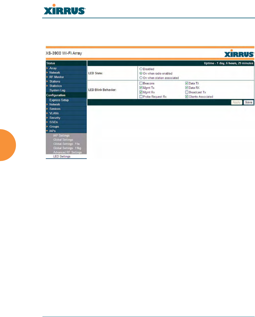
Wi-Fi Array
226 Configuring the Wi-Fi Array
LED Settings
This window assigns behavior preferences for the Array’s IAP LEDs.
Figure 125. LED Settings
Procedure for Configuring the IAP LEDs
1. LED State: This option determines which event triggers the LEDs, either
when an IAP is enabled or when an IAP first associates with the network.
Choose On Radio Enabled or On First Association, as desired. You may
also choose Disabled to keep the LEDs from being lit. The LEDs will still
light during the boot sequence, then turn off.
2. LED Blink Behavior: This option allows you to select when the IAP LEDs
blink, based on the activities you check here. From the choices available,
select one or more activities to trigger when the LEDs blink.
See also, “Array LED Operating Sequences” on page 74.
3. Click on the Apply button to apply the new settings to this session, or
click Save to apply your changes and make them permanent.
See Also

Wi-Fi Array
Configuring the Wi-Fi Array 227
Global Settings (IAP)
Global Settings .11an
Global Settings .11bgn
IAPs
LED Boot Sequence
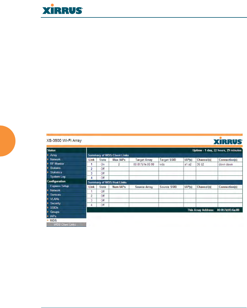
Wi-Fi Array
228 Configuring the Wi-Fi Array
WDS
This is a status only window that provides an overview of all WDS links that have
been defined. WDS (Wireless Distribution System) is a system that enables the
interconnection of access points wirelessly, allowing your wireless network to be
expanded using multiple access points without the need for a wired backbone to
link them. The Summary of WDS Client Links shows the WDS links that you
have defined on this Array and identifies the target Array for each by its base
MAC address. The Summary of WDS Host Links shows the WDS links that have
been established on this Array as a result of client Arrays associating to this Array
(i.e., the client Arrays have this Array as their target). The summary identifies the
source (client) Array for each link. Both summaries identify the IAPs that are part
of the link and whether the connection for each is up or down. See “WDS
Planning” on page 46 for an overview.
Figure 126. WDS
About Configuring WDS Links
A WDS link connects a client Array and a host Array (see Figure 127 on page 230).
The host must be the Array that has a wired connection to the LAN. Client links
from one or more Arrays may be connected to the host, and the host may also
have client links. See “WDS Planning” on page 46 for more illustrations.
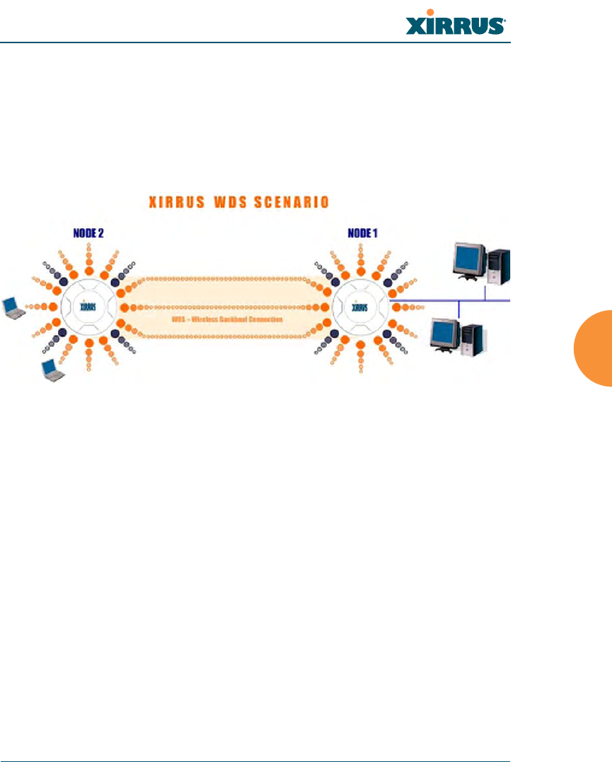
Wi-Fi Array
Configuring the Wi-Fi Array 229
The configuration for WDS is performed on the client Array only, as described in
“WDS Client Links” on page 231. No WDS configuration is performed on the host
Array. First you will set up a client link, defining the target (host) Array and SSID,
and the maximum number of IAPs in the link. Then you will select the IAPs to be
used in the link. When the client link is created, each member IAP will associate to
an IAP on the host Array.
Figure 127. .Configuring a WDS Link
See Also
SSID Management
WDS Client Link IAP Assignments:
WDS Client Links
WDS Statistics
#Once an IAP has been selected to act as a WDS client link, you will not be
allowed to use auto-configured cell sizing on that IAP (since the cell must
extend all the way to the other Array).
a2(52)
a3(149)
a4(40)
a10(52)
a9(149)
a8(40)
CLIENT HOST
Wired LAN
Client
Link
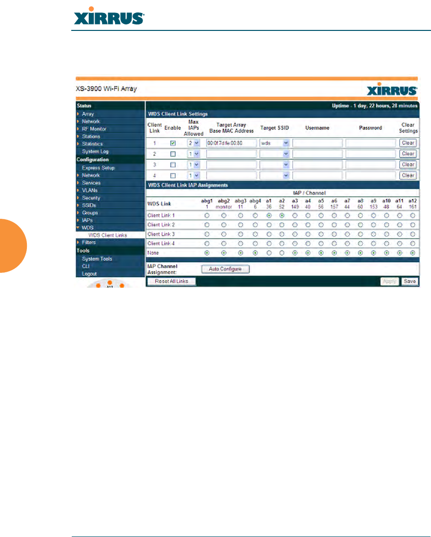
Wi-Fi Array
230 Configuring the Wi-Fi Array
WDS Client Links
This window allows you to set up a maximum of four WDS client links.
Figure 128. WDS Client Links
Procedure for Setting Up WDS Client Links
WDS Client Link Settings:
1. Client Link: Shows the ID (1 to 4) of each of the four possible WDS links.
2. Enabled: Check this box if you want to enable this WDS link, or uncheck
the box to disable the link.
3. Max IAPs Allowed (1-3): Enter the maximum number of IAPs for this
link, between 1 and 3.
4. Target Array Base MAC Address: Enter the base MAC address of the
target Array (the host Array at the other side of this link). To find this
MAC address, open the WDS window on the target Array, and use This
Array Address located on the right under the Summary of WDS Host
Links.

Wi-Fi Array
Configuring the Wi-Fi Array 231
5. Target SSID: Enter the SSID that the target Array is using.
6. Username: Enter a username for this WDS link. A username and
password is required if the SSID is using PEAP for WDS authentication
from the internal RADIUS server.
7. Password: Enter a password for this WDS link.
8. Clear Settings: Click on the Clear button to reset all of the fields on this
line.
9. Click on the Apply button to apply your changes to this session, or click
Save to apply your changes and make them permanent.
WDS Client Link IAP Assignments:
10. For each desired client link, select the IAPs that are part of that link.
11. Auto Configure: Click this button to instruct the Array to automatically
determine the best channel allocation settings for each IAP that
participates in a WDS link, based on changes in the environment. These
changes are executed immediately, and are automatically applied.
12. Reset All Links: this command tears down all links configured on the
Array and sets them back to their factory defaults, effective immediately.
See Also
SSID Management
WDS Planning
WDS
WDS Statistics
#Once an IAP has been selected to act as a WDS client link, no other
association will be allowed on that IAP. However, wireless associations will
be allowed on the WDS host side of the WDS session.
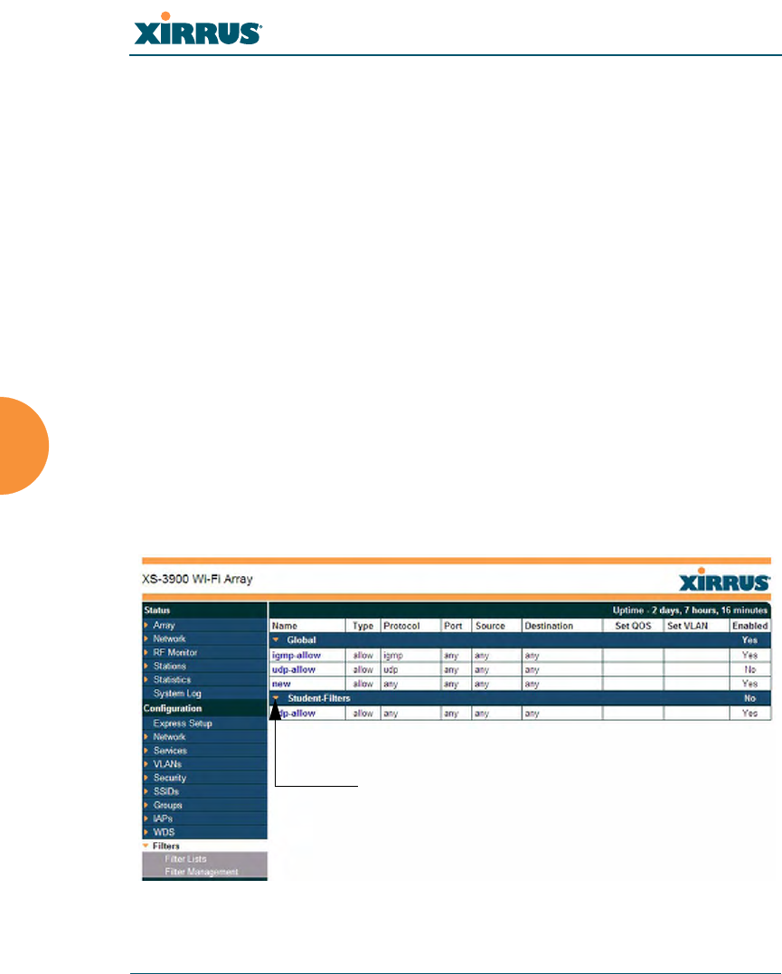
Wi-Fi Array
232 Configuring the Wi-Fi Array
Filters
The Wi-Fi Array’s integrated firewall uses stateful inspection to speed the
decision of whether to allow or deny traffic. Filters are also used to define the
rules used for blocking or passing traffic.
User connections managed by the firewall are maintained statefully—once a user
flow is established through the Array, it is recognized and passed through
without application of all defined filtering rules. Stateful inspection runs
automatically on the Array. The rest of this section describes how to view and
manage filters.
Filters are organized in groups, called Filter Lists. A filter list allows you to apply
a uniform set of filters to SSIDs or Groups very easily.
The read-only Filters window provides you with an overview of all filter lists that
have been defined for this Array, and the filters that have been created in each list.
Filters are listed in the left side column by name under the filter list to which they
belong. Each filter entry includes information about the type of filter, the protocol
it is filtering, which port it applies to, source and destination addresses, any QoS
definition, and affected VLAN assignments.
Figure 129. Filters
Orange arrow
expands/collapses display
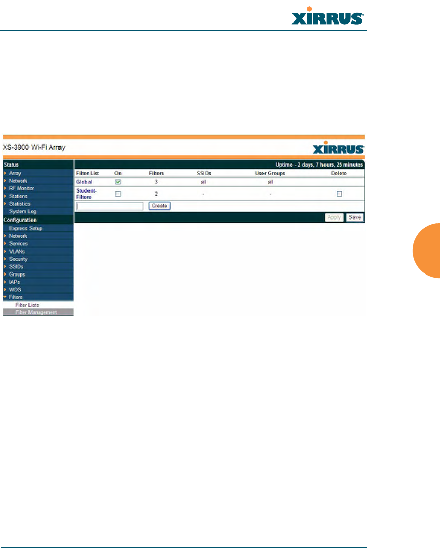
Wi-Fi Array
Configuring the Wi-Fi Array 233
Filter Lists
This window allows you to create filter lists. The Array comes with one
predefined list, named Global, which cannot be deleted. Filter lists (including
Global) may be applied to SSIDs or to Groups. Only one filter list at a time may be
applied to a group or SSID (although the filter list may contain a number of
filters). All filters are created within filter lists.
Figure 130. Filter Lists
Procedure for Managing Filter Lists
1. New Filter List Name: Enter a name for the new filter list in this field,
then click on the Create button to create the list. All new filters are
disabled when they are created. The new filter list is added to the Filter
List table in the window. Click on the filter list name, and you will be
taken to the Filter Management window for that filter list.
2. On: Check this box to enable this filter list, or leave it blank to disable the
list. If the list is disabled, you may still add filters to it or modify it, but
none of the filters will be applied to data traffic.
3. Filters: This read-only field displays the number of filters that belong to
this filter list.
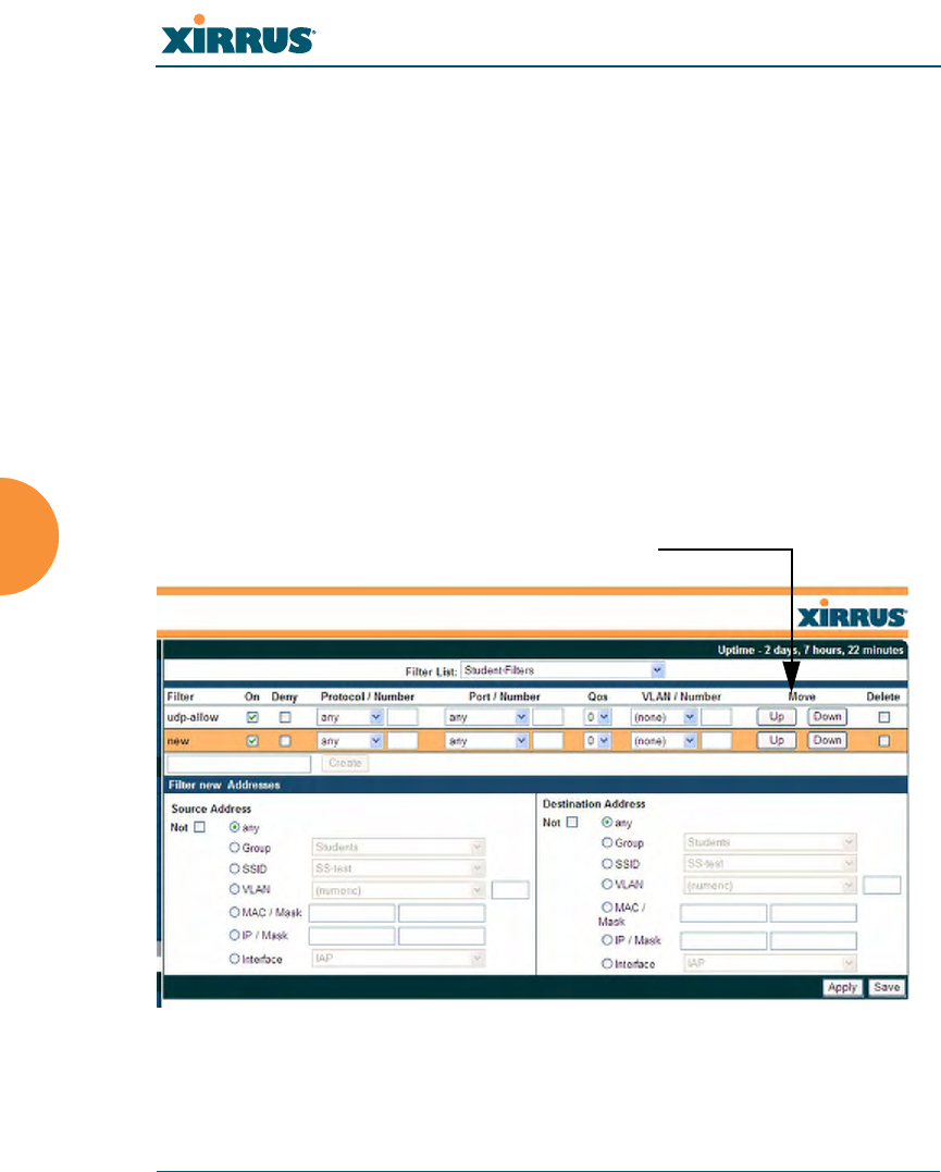
Wi-Fi Array
234 Configuring the Wi-Fi Array
4. SSIDs: This read-only field lists the SSIDs that use this filter list.
5. User Groups: This read-only field lists the Groups that use this filter list.
6. Delete: Click this checkbox and then click the Apply or Save button to
delete this filter list.
7. Click on the Apply button to apply your changes to the selected filter, or
click Save to apply your changes and make them permanent.
8. Click a filter list to go to the Filter Management window to create and
manage the filters that belong to this list.
Filter Management
This window allows you to create and manage filters for a selected filter list,
based on the filter criteria you specify.
Figure 131. Filter Management
Filters are applied in order, from top to bottom.
Click here to change the order.

Wi-Fi Array
Configuring the Wi-Fi Array 235
Note that filtering is secondary to the stateful inspection performed by the
integrated firewall. Traffic for established connections is passed through without
the application of these filtering rules.
Procedure for Managing Filters
1. Filter List: Select the filter list to display and manage on this window. All
of the filters already defined for this list are shown, and you may create
additional filters for this list.
2. New Filter Name: Enter a name for the new filter in the field next to the
Create button, then click on the Create button to create the filter. All new
filters are added to the table of filters at the top of the window. The filter
name must be unique within the list, but it may have the same name as a
filter in a different filter list. Two filters with the same name in different
filter lists will be completely unrelated to each other—they may be
defined with different parameter values.
3. Filter: Choose a filter entry to modify from the list at the top of the
window.
4. On: Use this field to enable or disable this filter.
5. Deny: Choose whether this filter will be an Allow filter or a Deny filter. If
you define the filter as an Allow filter, then any associations that meet the
filter criteria will be allowed. If you define the filter as a Deny filter, any
associations that meet the filter criteria will be denied.
6. Protocol: Choose a specific filter protocol from the pull-down list, or
choose numeric and enter a Number, or choose any to instruct the Array
to use the best filter.
7. Port: From the pull-down list, choose the type of port on which you want
this filter to be active, or choose 1-65534 and enter a Number, or choose
any to instruct the Array to apply the filter to any port.
8. Set QoS: Choose the QoS level (0 to 3) from the pull-down list. Level 0
has the lowest priority; level 3 has the highest priority. See
“Understanding QoS Priority on the Wi-Fi Array” on page 186.

Wi-Fi Array
236 Configuring the Wi-Fi Array
9. VLAN ID: (Optional) From the pull-down list, select a VLAN for this
filter to match. Select numeric and enter the number of a previously
defined VLAN (see “VLANs” on page 161).
10. Move Up/Down: The filters are applied in the order in which they are
displayed in the list, with filters on the top applied first. To change an
entry’s position in the list, just click its Up or Down button.
11. Source Address: Define a source address. Click the radio button for the
desired type of address (or other attribute) to match. Then specify the
value to match in the field to the right of the button. Choose Any to use
any source address. Check Not to match any address except for the
specified address.
12. Destination Address: Define a destination address. Click the radio
button for the desired type of address (or other attribute) to match. Then
specify the value to match in the field to the right of the button. Choose
Any to use any source address. Check Not to match any address except
for the specified address.
13. To delete a filter, check its Delete checkbox, then click the Apply or Save
button.
14. Click on the Apply button to apply your changes to the selected filter, or
click Save to apply your changes and make them permanent.
See Also
Filters
Filter Statistics
Understanding QoS Priority on the Wi-Fi Array
VLANs

Wi-Fi Array
Configuring the Wi-Fi Array 237

Wi-Fi Array
238 Configuring the Wi-Fi Array

Wi-Fi Array
Using Tools on the Wi-Fi Array 239
Using Tools on the Wi-Fi Array
These WMI windows allow you to perform administrative tasks on your Array,
such as upgrading software, rebooting, uploading and downloading
configuration files, and other utility tasks. Tools are described in the following
sections:
z“System Tools” on page 240
z“CLI” on page 246
z“Logout” on page 248
This section does not discuss using status or configuration windows. For
information on those windows, please see:
z“Viewing Status on the Wi-Fi Array” on page 91
z“Configuring the Wi-Fi Array” on page 133
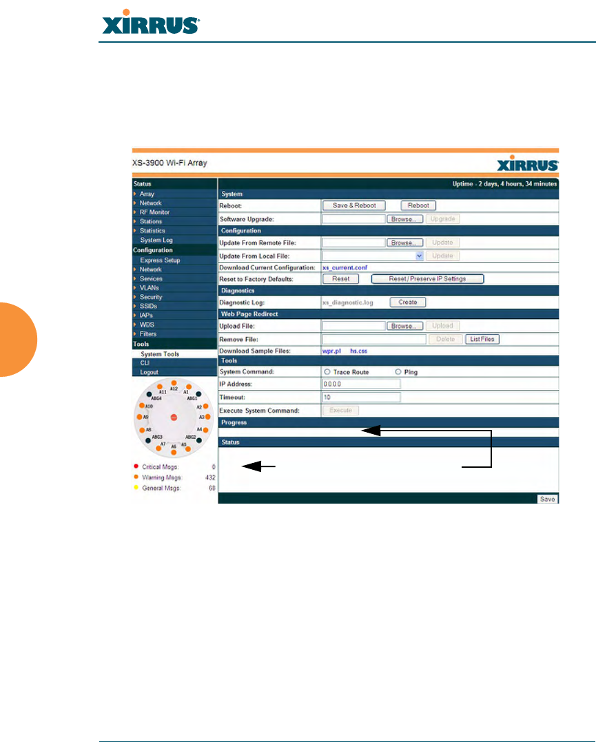
Wi-Fi Array
240 Using Tools on the Wi-Fi Array
System Tools
This window allows you to manage files for software images, configuration, and
Web Page Redirect (WPR), manage the system’s configuration parameters, reboot
the system, and use diagnostic tools.
Figure 132. System Tools
Status is
shown here
Progress is
shown here

Wi-Fi Array
Using Tools on the Wi-Fi Array 241
Procedure for Configuring System Tools
System:
1. Save & Reboot or Reboot: Use Save & Reboot to save the current
configuration and then reboot the Array. The LEDs on the Array indicate
the progress of the reboot, as described in “Powering Up the Wi-Fi Array”
on page 73. Alternatively, you can click on the Reboot button to discard
any configuration changes which have not been saved since the last
reboot. You will be warned if you have unsaved changes.
2. Software Upgrade: This Feature allows upgrading the ArrayOS to a
newer version provided by Xirrus. Enter the filename and directory
location (or click on the Browse button to locate the software upgrade
file), then click on the Upgrade button to upload the new file to the Array.
Progress of the operation will be displayed below, in the Progress section.
Completion status of the operation is shown in the Status section.
This operation does not run the new software or change any configured
values. The existing software continues to run on the Array until you
reboot, at which time the uploaded software will be used.
Configuration:
3. Update from Remote File: This field allows you to define the path to a
configuration file (one that you previously saved—see Step 5 below).
Click on the Browse button if you need to browse for the location of the
file, then click Update to update your configuration settings.
4. Update from Local File: This field updates Array settings from a local
configuration file on the Array. Select one of the following files from the
drop-down list:
•factory.conf: The factory default settings
•lastboot.conf: The setting values from just before the last reboot
#If you are having difficulty upgrading the Array using the WMI, there is a
lower-level procedure that you may use. See “Upgrading the Array via CLI”
on page 344.

Wi-Fi Array
242 Using Tools on the Wi-Fi Array
•saved.conf: The last settings that were explicitly saved
Click Update to update your configuration settings.
5. Download Current Configuration: Click on the link titled
xs_current.conf to download the Array’s current configuration settings to
a file (that you can upload back to the Array at a later date). The system
will prompt you for a destination for the file. The file will contain the
Array’s current configuration values.
6. Reset to Factory Defaults: Click on the Reset/Preserve IP Settings button
to reset the system’s current configuration settings to the factory default
values, except for the Array’s management IP address which is left unchanged.
This function allows you to maintain management connectivity to the
Array even after the reset. This will retain the Gigabit Ethernet port’s IP
address (see “Network Interfaces” on page 141), or if you have
configured management over a VLAN it will maintain the management
VLAN’s IP address (see “VLAN Management” on page 162). All other
previous configuration settings will be lost.
Click Reset to reset all of the system’s current configuration settings to
the factory default values, including the management IP address—all
previous configuration settings will be lost. The Array’s Gigabit Ethernet
ports default to using DHCP to obtain an IP address.
#Important! When you have initially configured your Array, or have made
significant changes to its configuration, we strongly recommend that you
save the configuration to a file in order to have a safe backup of your working
configuration.
#If the IP settings change, the connection to the WMI may be lost.
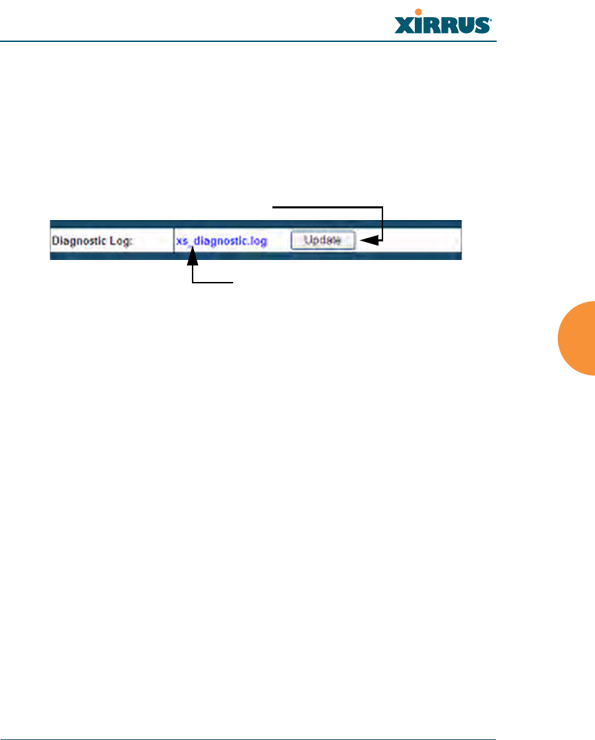
Wi-Fi Array
Using Tools on the Wi-Fi Array 243
Diagnostics:
7. Diagnostic Log: Click the Create button to save a snapshot of Array
information for use by Xirrus Customer Support personnel. The filename
xs_diagnostic.log will be displayed in blue and it becomes a link to the
newly created log file. Click the link to download this file to the C:\
folder on your local computer. (Figure 133 )
Figure 133. Saving the Diagnostic Log
This feature is only used at the request of Customer Support. It saves all
of the information regarding your Array, including status, configuration,
statistics, log files, and recently performed actions.
The diagnostic log is always saved as a file named xs_diagnostic.log
on your C:\ drive, so you should immediately rename the file to save it.
This way, it will not be lost the next time you save a diagnostic log. Often,
Customer Support will instruct you to save two diagnostic logs about ten
minutes apart so that they can examine the difference in statistics
between the two snapshots (for example, to see traffic and error statistics
for the interval). Thus, you must rename the first diagnostic log file.
#All passwords are stored on the array in an encrypted form and will not be
exposed in the diagnostic log.
Click Update to create log
Then click this link to save
log file to local computer
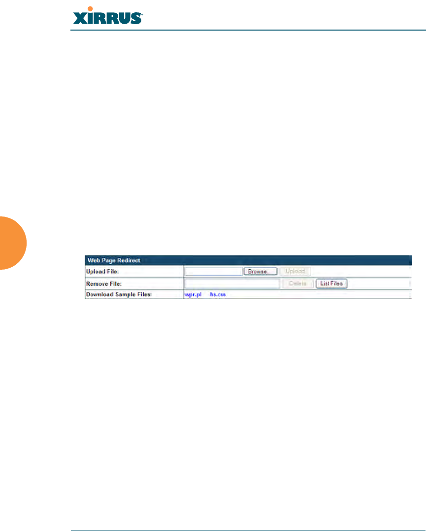
Wi-Fi Array
244 Using Tools on the Wi-Fi Array
Web Page Redirect:
The Array uses a Perl script and a cascading style sheet to define the default
splash/login Web page that the Array delivers for WPR. You may replace
these files with files for one or more custom pages of your own. See Step 10
below to view the default files. See Step 14 on page 192 for more information
about WPR and how the splash/login page is used.
Each SSID that has WPR enabled may have its own page. Custom files for a
specific SSID must be named based on the SSID name. For example, if the
SSID is named Public, the default wpr.pl and hs.css files should be
modified as desired and renamed to wpr-Public.pl and hs-Public.css
before uploading to the Array. If you modify and upload files named wpr.pl
and hs.css , they will replace the factory default files and will be used for
any SSID that does not have its own custom files, per the naming convention
just described. Be careful not to replace the default files unintentionally.
Figure 134. Managing WPR Splash/Login page files
8. Upload File: Use this to install files for your own custom WPR splash/
login page (as described above) on the Array. Note that uploaded files are
not immediately used - you must reboot the Array first. At that time, the
Array looks for and uses these files, if found.
Enter the filename and directory location (or click Browse to locate the
splash/login page files), then click on the Upload button to upload the
new files to the Array. You must reboot to make your changes take effect.
9. Remove File: Enter the name of the WPR file you want to remove, then
click on the Delete button. You can use the List Files button to show you
a list of files that have been saved on the Array for WPR. The list is
displayed in the Status section at the bottom of the WMI window. You
must reboot to make your changes take effect.
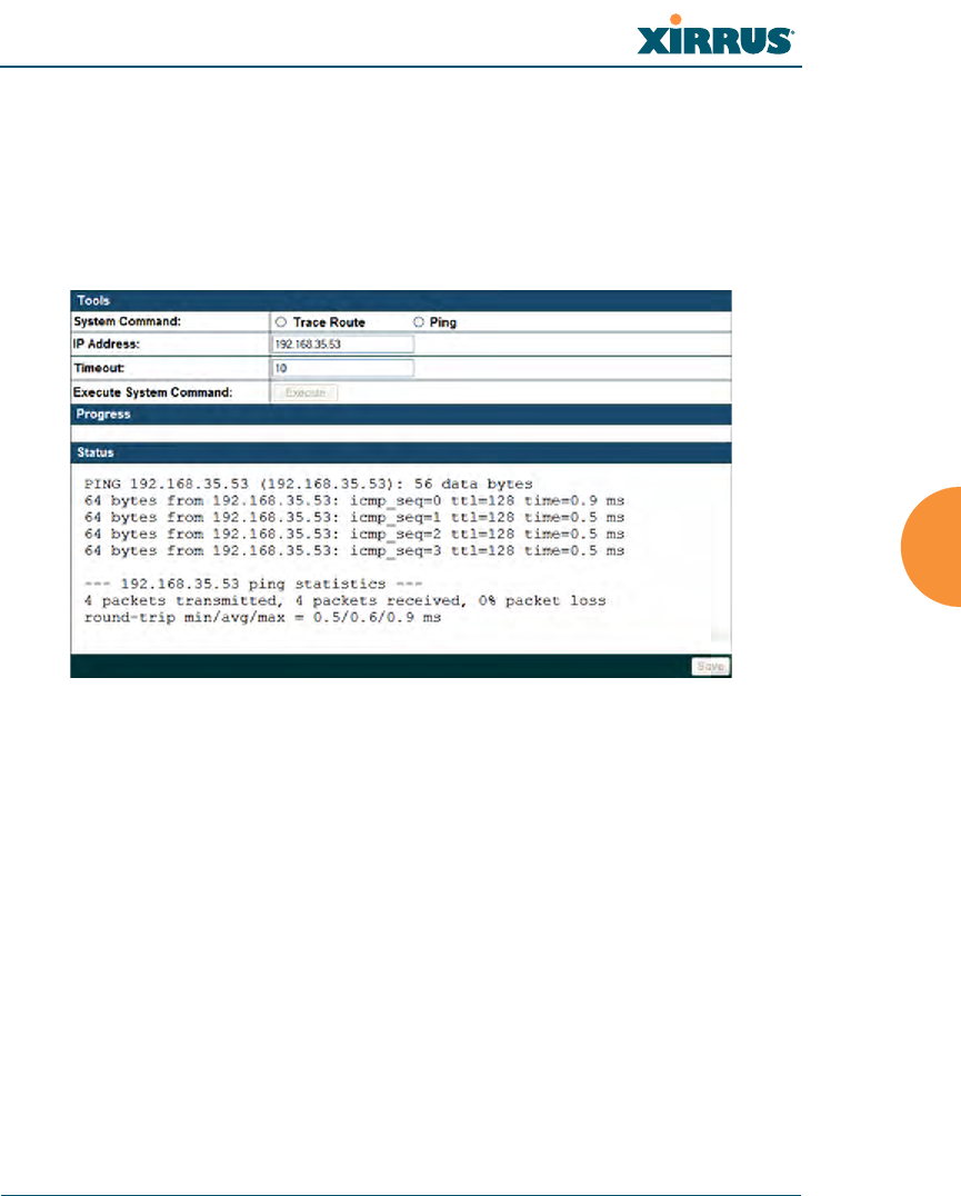
Wi-Fi Array
Using Tools on the Wi-Fi Array 245
10. Download Sample Files: Click on a link to access the corresponding
sample WPR files:
•wpr.pl—a sample Perl script.
•hs.css—a sample cascading style sheet.
Tools:
Figure 135. System Command (Ping)
11. System Command: Choose Trace Route or Ping.
12. IP Address: Enter the IP address of the target device.
13. Timeout: Enter a value (in seconds) before the action times out.
14. Execute System Command: Click Execute to start the specified
command. Progress of command execution is displayed in the Progress
frame. Results are displayed in the Status frame.
Progress and Status Frames:
The Progress frame displays a progress bar for commands such as software
upgrade and ping. The Status frame presents the output from system
commands (ping and traceroute), as well as other information, such as the
results of software upgrade.
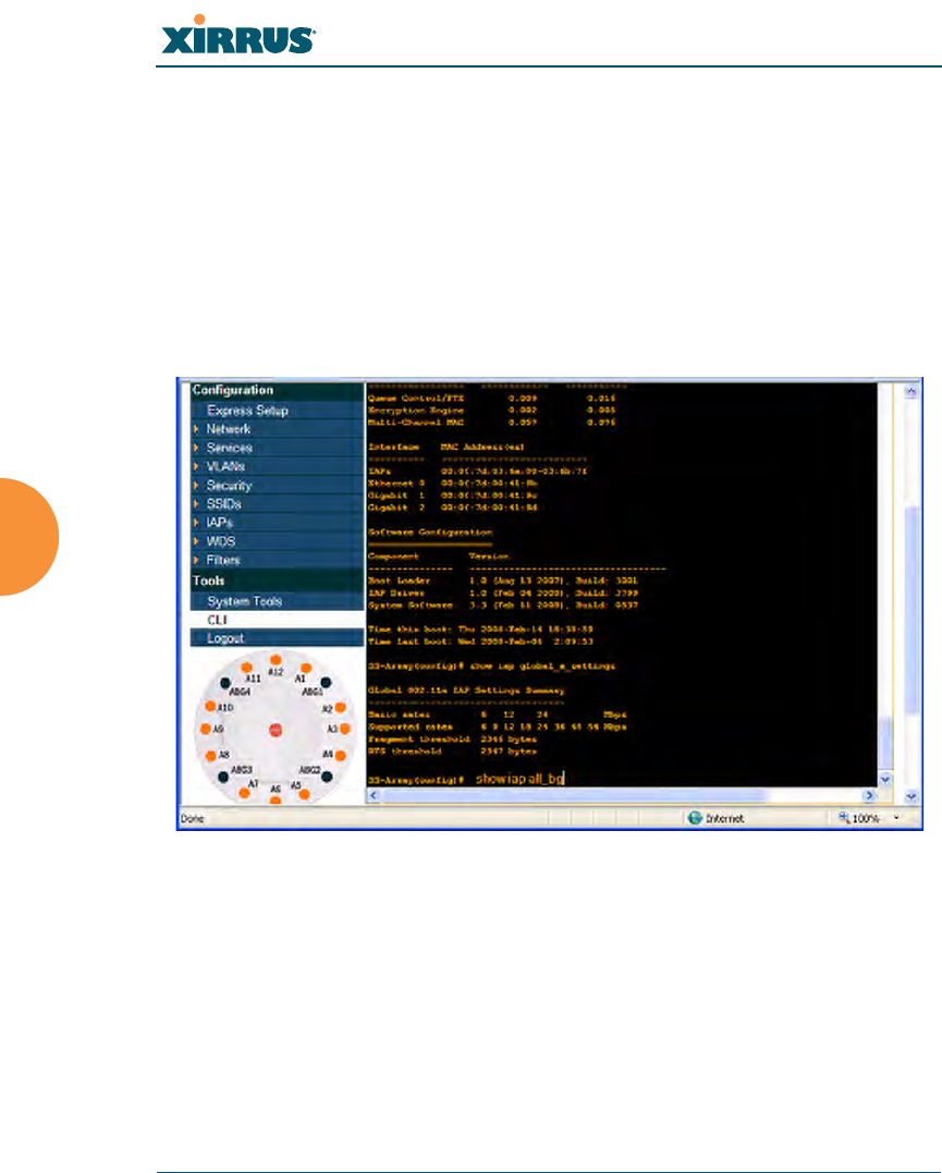
Wi-Fi Array
246 Using Tools on the Wi-Fi Array
15. If you want to save the parameters you established in this window for
future sessions, click on the Save button.
CLI
The WMI provides this window to allow you to use the Array’s Command Line
Interface (CLI). You can enter commands to configure the Array, or display
information using show commands. You will not need to log in - you already
logged in to the Array when you started the WMI.
Figure 136. CLI Window
To enter a command, simply type it in. The command is echoed and output is
shown in the normal way—that is, the same way it would be if you were using
the CLI directly. You may use the extra scroll bar inside the right edge of the
window to scroll through your output.
This window has some minor differences, compared to direct use of the CLI via
the console or an SSH connection:

Wi-Fi Array
Using Tools on the Wi-Fi Array 247
zThe CLI starts in config mode. All configuration and show commands are
available in this mode. You can “drill down” the mode further in the
usual way. For example, you can type interface iap to change the mode to
config-iap. The prompt will indicate the current command mode, for
example:
My-Array(config-iap) #
zYou can abbreviate a command and it will be executed if you have typed
enough of the command to be unambiguous. The command will not
auto-complete, however. Only the abbreviated command that you
actually typed will be shown. You can type a partial command and press
Tab to have the command auto-complete. If the partial command is
ambiguous a list of legal endings is displayed.
zEntering quit will log you out of the current WMI session.
Help commands (the ? character) are available, either at the prompt or after you
have typed part of a command.
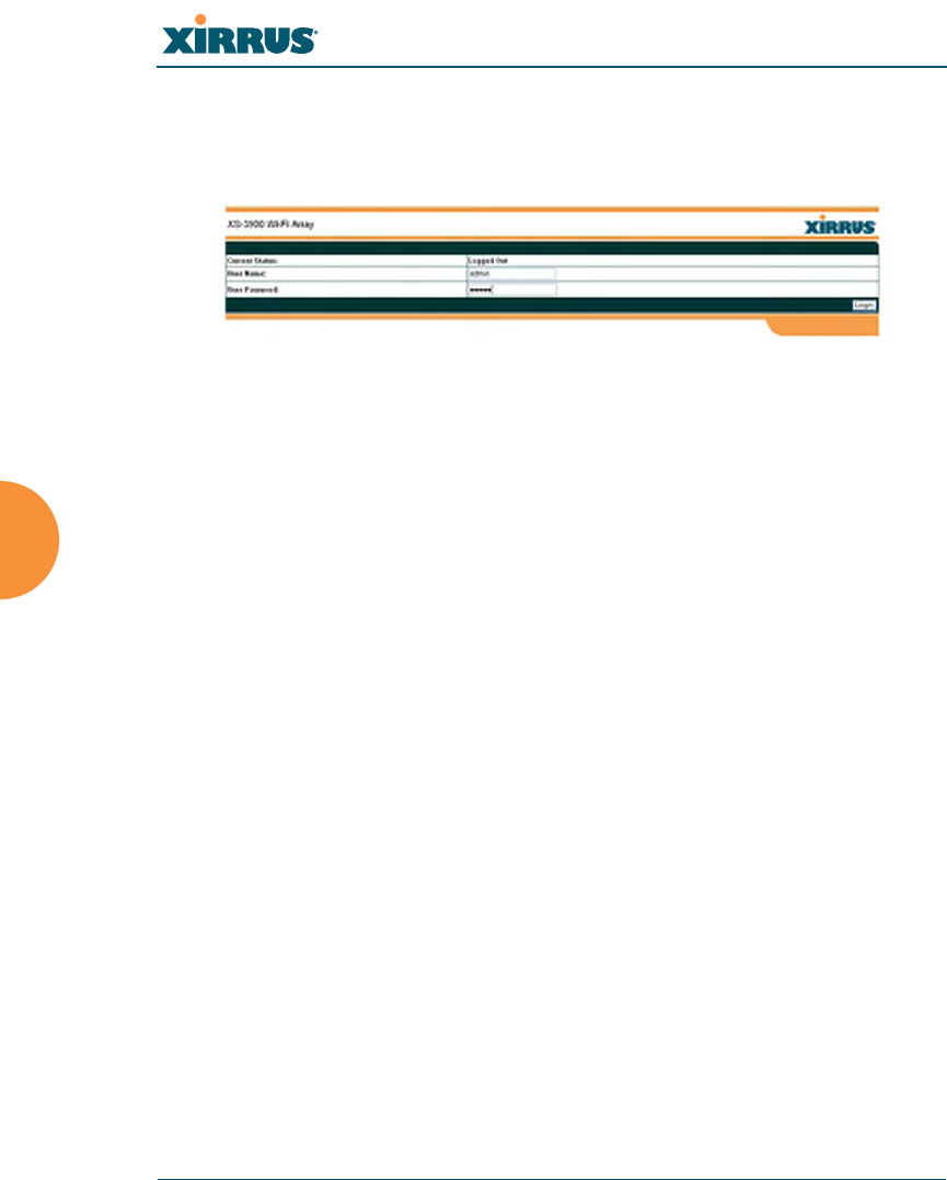
Wi-Fi Array
248 Using Tools on the Wi-Fi Array
Logout
Click on the Logout button to terminate your session. When the session is
terminated, you are presented with the Array’s login window.
Figure 137. Login Window
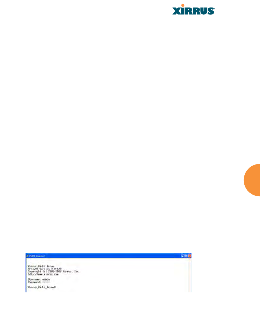
Wi-Fi Array
The Command Line Interface 249
The Command Line Interface
This section covers the commands and the command structure used by the Wi-Fi
Array’s Command Line Interface (CLI), and provides a procedure for establishing
a Telnet connection to the Array. Topics discussed include:
z“Establishing a Secure Shell (SSH) Connection” on page 249.
z“Getting Started with the CLI” on page 250.
z“Top Level Commands” on page 252.
z“Configuration Commands” on page 260.
z“Sample Configuration Tasks” on page 291.
See Also
Establishing Communication with the Array
Network Map
System Tools
Establishing a Secure Shell (SSH) Connection
Use this procedure to initialize the system and log in to the Command Line
Interface (CLI) via a Secure Shell (SSH) utility, such as PuTTY.
1. Start your SSH session and communicate with the Array via its default IP
address (10.0.2.1 for both the Gigabit 1 and Gigabit 2 Ethernet ports).
2. At the login prompt, enter your user name and password (the default for
both is admin). Login names and passwords are case-sensitive. You are
now logged in to the Array’s Command Line Interface.
Figure 138. Logging In
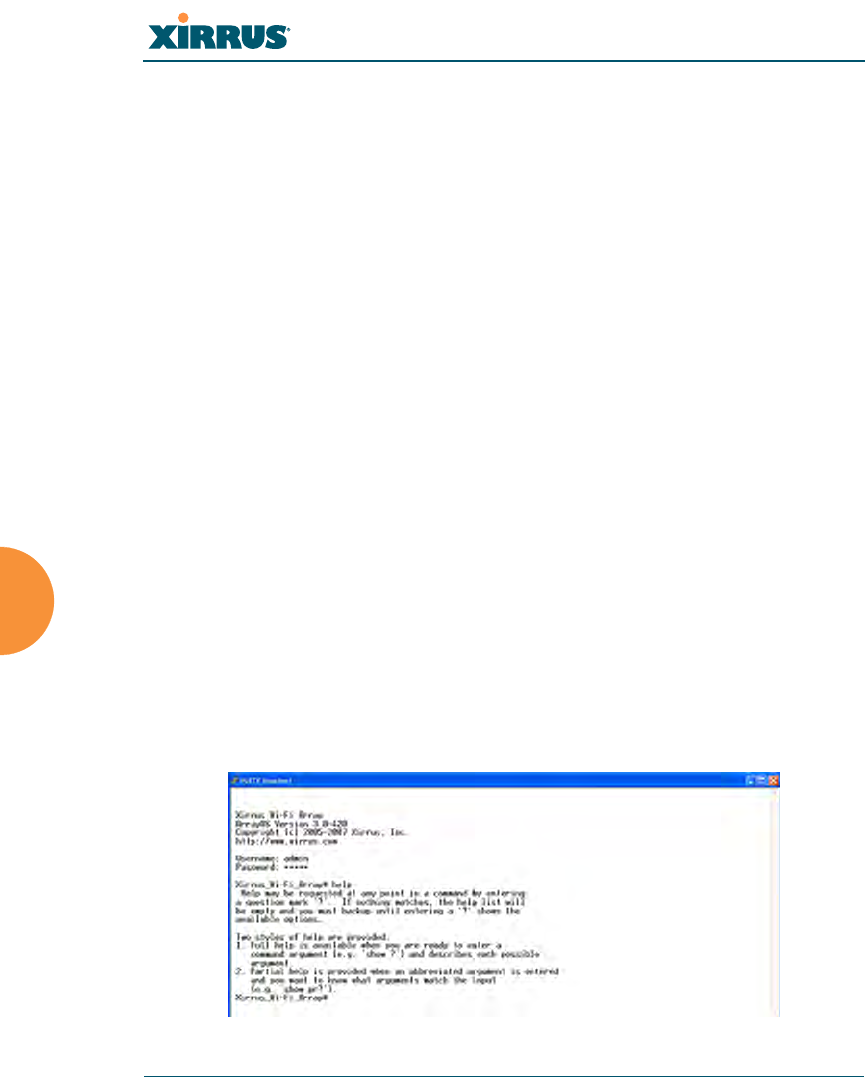
Wi-Fi Array
250 The Command Line Interface
Getting Started with the CLI
The root command prompt (Root Command Prompt) is the first prompt you see
after logging in to the CLI. If you are at a level other than the root command
prompt you can return to this prompt at any time by using the exit command to
step back through each command prompt level. The root command prompt you
see in the CLI window is determined by the host name you assigned to your
Array. The prompt Xirrus_Wi-Fi_Array is displayed throughout this document
simply because this is the host name assigned to the Array used for development.
To terminate your session at any time, use the quit command.
Note: If you terminate your session, with either the quit or exit command, your WMI
session will also be terminated.
Inputting Commands
When inputting commands you need only type as many characters as the system
requires before it recognizes your input. For example, you can type the
abbreviated term config to access the configure prompt.
Getting Help
The CLI offers the following two levels of assistance:
zhelp Command
The help command is only available at the root command prompt.
Initiating this command generates a window that provides information
about the types of help that are available with the CLI.
Figure 139. Help Window
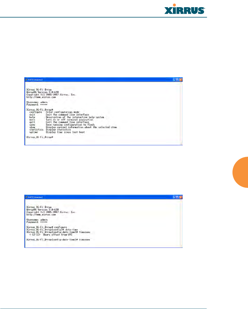
Wi-Fi Array
The Command Line Interface 251
z? Command
This command is available at any prompt and provides either FULL or
PARTIAL help. Using the ? (question mark) command when you are
ready to enter an argument will display all the possible arguments (full
help). Partial help is provided when you enter an abbreviated argument
and you want to know what arguments will match your input.
Figure 140. Full Help
Figure 141 shows an example of how the Help system can provide the
argument and format when specifying the time zone under the date-time
command.
Figure 141. Partial Help
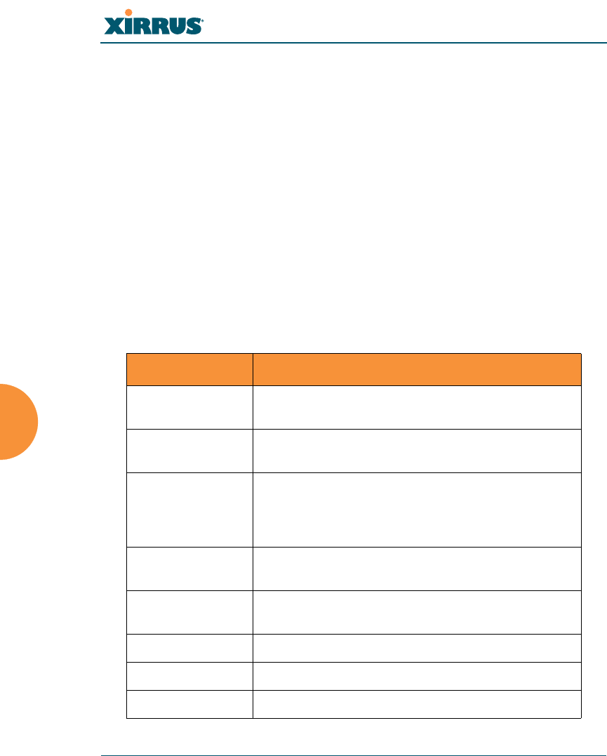
Wi-Fi Array
252 The Command Line Interface
Top Level Commands
This section offers an at-a-glance view of all top level commands—organized
alphabetically. Top level commands are defined here as commands that are
directly accessible from the root command prompt (Xirrus_Wi-Fi_Array#). The
root command prompt is based on the host name assigned to your Array. When
inputting commands, be aware that all commands are case-sensitive.
All other commands are considered second level configuration commands—these
are the commands you use to configure specific elements of the Array’s features
and functionality. For a listing of these commands with examples of command
formats and structure, go to “Configuration Commands” on page 260.
Root Command Prompt
The following table shows the top level commands that are available from the
root command prompt [Xirrus_Wi-Fi_Array].
Command Description
@ Type @n to execute command n (as shown by the
history command).
configure Enter the configuration mode. See “Configuration
Commands” on page 260.
exit Exit the CLI and terminate your session—if this
command is used at any level other than the root
command prompt you will simply exit the current
level (step back) and return to the previous level.
help Show a description of the interactive help system.
See also, “Getting Help” on page 250.
history List history of commands that have been
executed.
more Turn terminal pagination ON or OFF.
quit Exit the Command Line Interface (from any level).
search Search for pattern in show command output.
Wi-Fi Array
The Command Line Interface 253
configure Commands
The following table shows the second level commands that are available with the
top level configure command [Xirrus_Wi-Fi_Array(config)#].
show Display information about the selected item. See
“show Commands” on page 256.
statistics Display statistical data about the Array. See
“statistics Commands” on page 259.
uptime Display the elapsed time since the last boot.
Command Description
@ Type @n to execute command n (as shown by the
history command).
acl Configure the Access Control List.
admin Define administrator access parameters.
cdp Configure Cisco Discovery Protocol settings.
clear Remove/clear the requested elements.
contact-info Contact information for assistance on this Array.
date-time Configure date and time settings.
dhcp-server Configure the DHCP Server.
dns Configure the DNS settings.
end Exit the configuration mode.
exit Go UP one mode level.
file Manage the file system.
filter Define protocol filter parameters.
group Define user groups with parameter settings
Command Description
Wi-Fi Array
254 The Command Line Interface
help Description of the interactive Help system.
history List history of commands that have been
executed.
hostname Host name for this Array.
https Enable/disable HTTPS.
interface Select the interface to configure.
load Load running configuration from flash
location Location name for this Array.
management Configure array management parameters
more Turn ON or OFF terminal pagination.
no Disable (if enabled) or set to default value.
quit Exit the Command Line Interface.
radius-server Configure the RADIUS server parameters.
reboot Reboot the Array.
reset Reset all settings to their factory default values
and reboot.
run-tests Run selective tests.
save Save the running configuration to FLASH.
search Search for pattern in show command output.
security Set the security parameters for the Array.
show Display current information about the selected
item.
snmp Enable, disable or configure SNMP.
ssh Enable/disable SSH.
Command Description
Wi-Fi Array
The Command Line Interface 255
ssid Configure the SSID parameters.
standby Configure the standby parameters.
statistics Display statistics.
syslog Enable, disable or configure the Syslog Server.
telnet Enable/disable Telnet.
uptime Display time since the last boot.
vlan Configure VLAN parameters.
Command Description
Wi-Fi Array
256 The Command Line Interface
show Commands
The following table shows the second level commands that are available with the
top level show command [Xirrus_Wi-Fi_Array# show].
Command Description
acl Display the Access Control List.
admin Display the administrator list.
array-info Display system information.
associated-
stations
Display stations that have associated to the Array.
boot-env Display Boot loader environment variables.
capabilities Display detailed station capabilities.
cdp Display Cisco Discovery Protocol settings.
channel-list Display list of Array’s 802.11an and b/g channels.
clear-text Display and enter passwords and secrets in the
clear.
conntrack Display the Connection Tracking table.
console Display terminal settings.
contact-info Display contact information.
country-list Display countries that the Array can be set to
support.
date-time Display date and time settings summary.
dhcp-leases Display IP addresses (leases) assigned to stations
by the DHCP server.
dhcp-pool Display internal DHCP server settings summary
information.
diff Display the difference between configurations.

Wi-Fi Array
The Command Line Interface 257
dns Display DNS summary information.
env-ctrl Display the environmental controller status for the
outdoor enclosure.
error-numbers Display the detailed error number in error
messages.
ethernet Display Ethernet interface summary information.
external-radius Display summary information for the external
RADIUS server settings.
factory-config Display the Array factory configuration
information.
filters Display filter information.
iap Display IAP configuration information.
internal-radius Display the users defined for the embedded
RADIUS server.
lastboot-config Display Array configuration at the time of the last
boot-up.
management Display settings for managing the Array, plus
Standby, and other information.
network-map Display network map information.
realtime-monitor Display realtime statistics for all IAPs.
rogue-ap Display rogue AP information.
route Display the routing table .
rssi-map Display RSSI map by IAP for station.
running-config Display configuration information for the Array
currently running.
saved-config Display the last saved Array configuration.
Command Description
Wi-Fi Array
258 The Command Line Interface
security Display security settings summary information.
self-test Display self test results.
snmp Display SNMP summary information.
spanning-tree Display spanning tree information.
spectrum-
analyzer
Display spectrum analyzer measurements.
ssid Display SSID summary information.
stations Display station information.
statistics Display statistics.
syslog Display the system log.
syslog-settings Display the system log (syslog) settings.
temperature Display the current board temperatures.
unassociated-
stations
Display unassociated station information.
vlan Display VLAN information.
wds Display WDS information.
<cr> Display configuration or status information.
Command Description

Wi-Fi Array
The Command Line Interface 259
statistics Commands
The following table shows the second level commands that are available with the
top level statistics command [Xirrus_Wi-Fi_Array# statistics].
Command Description
ethernet Display statistical data for all Ethernet interfaces.
Ethernet Name
eth0, gig1, gig2
Display statistical data for the defined Ethernet
interface (either eth0, gig1 or gig2).
FORMAT:
statistics gig1
filter Display statistics for defined filters (if any). .
FORMAT:
statistics filter [detail]
iap Display statistical data for the defined IAP.
FORMAT:
statistics iap abg4
station Display statistical data about associated stations.
FORMAT:
statistics station billw
vlan Display statistical data for the defined VLAN. You
must use the VLAN number (not its name) when
defining a VLAN.
FORMAT:
statistics vlan 1
wds Display statistical data for the defined active WDS
(Wireless Distribution System) links.
FORMAT:
statistics wds 1
<cr> Display configuration or status information.
Wi-Fi Array
260 The Command Line Interface
Configuration Commands
All configuration commands are accessed by using the configure command at the
root command prompt (Xirrus_Wi-Fi_Array#). This section provides a brief
description of each command and presents sample formats where deemed
necessary. The commands are organized alphabetically. When inputting
commands, be aware that all commands are case-sensitive.
To see examples of some of the key configuration tasks and their associated
commands, go to “Sample Configuration Tasks” on page 291.
acl
The acl command [Xirrus_Wi-Fi_Array(config)# acl] is used to configure the
Access Control List.
Command Description
add Add a MAC address to the list.
FORMAT:
acl add AA:BB:CC:DD:EE:FF
del Delete a MAC address from the list.
FORMAT:
acl del AA:BB:CC:DD:EE:FF
disable Disable the Access Control List
FORMAT:
acl disable
enable Enable the Access Control List
FORMAT:
acl enable
reset Delete all MAC addresses from the list.
FORMAT:
acl reset

Wi-Fi Array
The Command Line Interface 261
admin
The admin command [Xirrus_Wi-Fi_Array(config-admin)#] is used to configure
the Administrator List.
Command Description
add Add a user to the Administrator List.
FORMAT:
admin add [userID]
check Check whether a user name is valid.
FORMAT:
admin check [userID]
del Delete a user to the Administrator List.
FORMAT:
admin del [userID]
edit Modify user in the Administrator List.
FORMAT:
admin edit [userID]
logout Log the user out.
FORMAT:
admin logout [userID]
reset Delete all users and restore the default user.
FORMAT:
admin reset
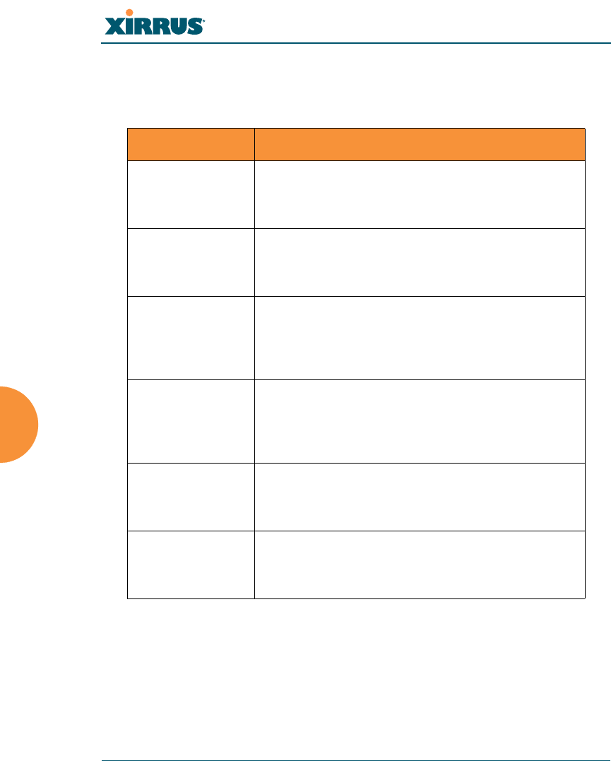
Wi-Fi Array
262 The Command Line Interface
cdp
The cdp command [Xirrus_Wi-Fi_Array(config)# cdp] is used to configure the
Cisco Discovery Protocol.
Command Description
disable Disable the Cisco Discovery Protocol
FORMAT:
cdp disable
enable Enable the Cisco Discovery Protocol
FORMAT:
cdp enable
hold-time Select CDP message hold time before messages
received from neighbors expire.
FORMAT:
cdp hold-time [# seconds]
interval The Array sends out CDP announcements at this
interval.
FORMAT:
cdp interval [# seconds]
off Disable the Cisco Discovery Protocol
FORMAT:
cdp off
on Enable the Cisco Discovery Protocol
FORMAT:
cdp on

Wi-Fi Array
The Command Line Interface 263
clear
The clear command [Xirrus_Wi-Fi_Array(config)# clear] is used to clear
requested elements.
Command Description
authentication Deauthenticate a station.
FORMAT:
clear station [authenticated station]
history Clear the history of CLI commands executed.
FORMAT:
clear history
screen Clear the screen where you’re viewing CLI
output.
FORMAT:
clear syslog
statistics Clear the statistics for a requested interface.
FORMAT:
clear statistics [eth0]
syslog Clear all syslog message, but continue to log new
messages.
FORMAT:
clear syslog
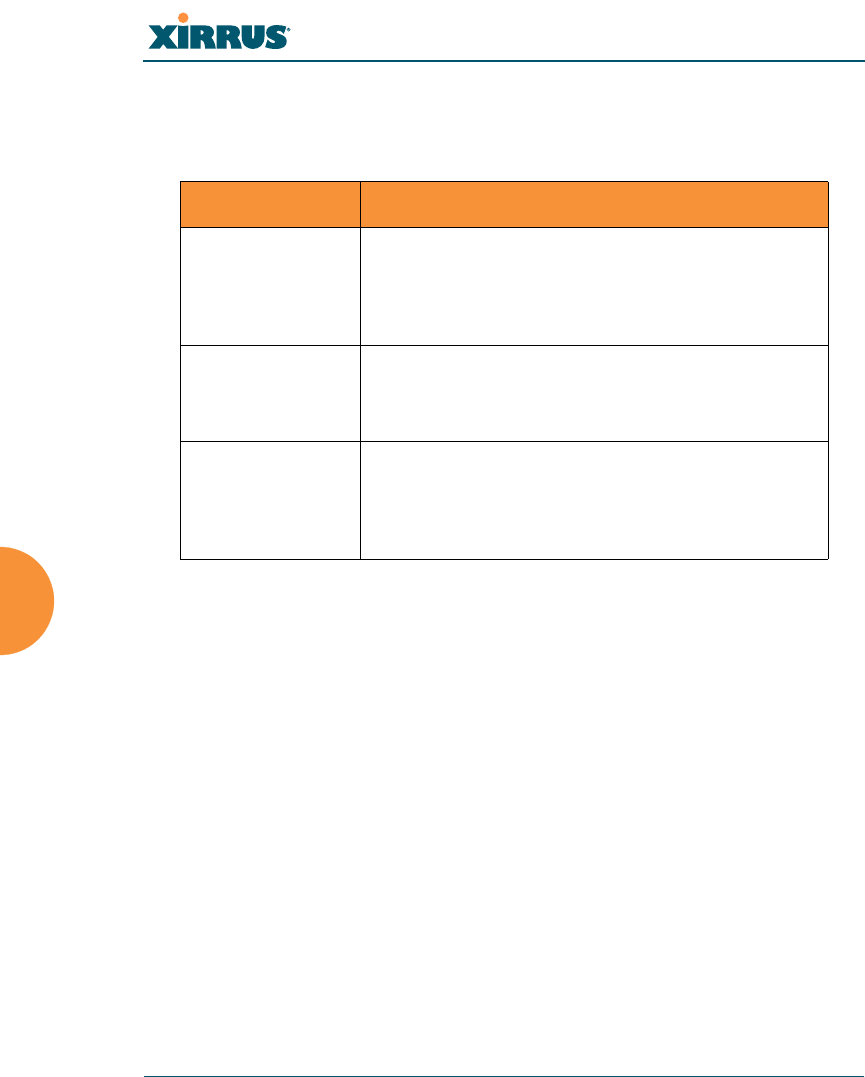
Wi-Fi Array
264 The Command Line Interface
contact-info
The contact-info command [Xirrus_Wi-Fi_Array(config)# contact-info] is used
for managing administrator contact information.
Command Description
email Add an email address for the contact (must be in
quotation marks).
FORMAT:
contact-info email [“contact@mail.com”]
name Add a contact name (must be in quotation marks).
FORMAT:
contact-info name [“Contact Name”]
phone Add a telephone number for the contact (must be
in quotation marks).
FORMAT:
contact-info phone [“8185550101”]
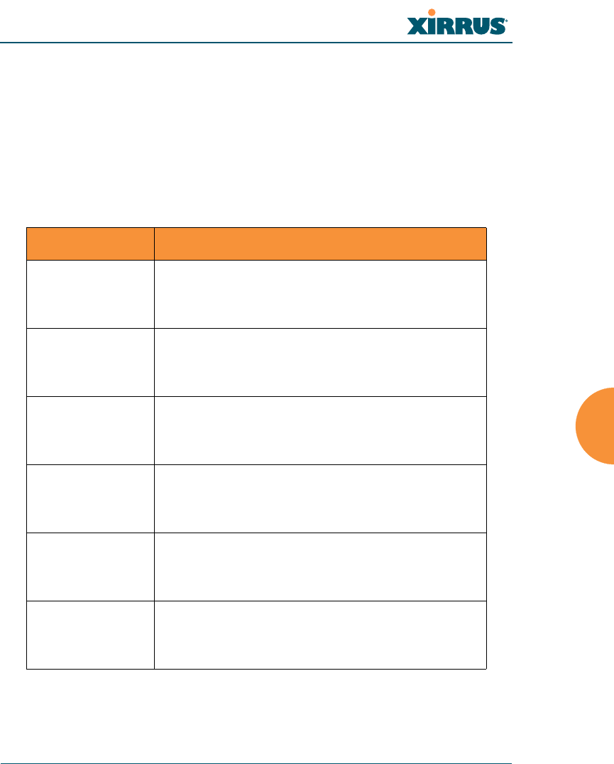
Wi-Fi Array
The Command Line Interface 265
date-time
The date-time command [Xirrus_Wi-Fi_Array(config-date-time)#] is used to
configure the date and time parameters. Your Array supports the Network Time
Protocol (NTP) in order to ensure that the Array’s internal time is accurate. NTP is
set to UTC time by default; however, you can set the time zone so that your Array
will display local time. This is done by defining an offset from the UTC value. For
example, Pacific Standard Time is 8 hours behind UTC time, so the offset from
UTC time would be -8.
Command Description
dst_adjust Enable adjustment for daylight savings.
FORMAT:
date-time dst_adjust
no Disable daylight savings adjustment.
FORMAT:
date-time no dst_adjust
ntp Enable the NTP server.
FORMAT:
date-time ntp on (or off to disable)
offset Set an offset from Greenwich Mean Time.
FORMAT:
date-time no dst_adjust
set Set the date and time for the Array.
FORMAT:
date-time set [10:24 10/23/2007]
timezone Configure the time zone.
FORMAT:
date-time timezone [-8]

Wi-Fi Array
266 The Command Line Interface
dhcp-server
The dhcp-server command [Xirrus_Wi-Fi_Array(config-dhcp-server)#] is used to
add, delete and modify DHCP pools.
Command Description
add Add a DHCP pool.
FORMAT:
dhcp-server add [dhcp pool]
del Delete a DHCP pool.
FORMAT:
dhcp-server del [dhcp pool]
edit Edit a DHCP pool
FORMAT:
dhcp-server edit [dhcp pool]
reset Delete all DHCP pools.
FORMAT:
dhcp-server reset
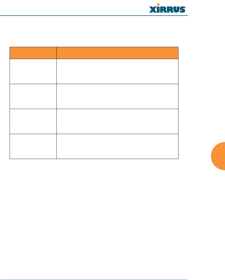
Wi-Fi Array
The Command Line Interface 267
dns
The dns command [Xirrus_Wi-Fi_Array(config-dns)#] is used to configure your
DNS parameters.
Command Description
domain Enter your domain name.
FORMAT:
dns domain [www.mydomain.com]
server1 Enter the IP address of the primary DNS server.
FORMAT:
dns server1 [1.2.3.4]
server2 Enter the IP address of the secondary DNS server.
FORMAT:
dns server1 [2.3.4.5]
server3 Enter the IP address of the tertiary DNS server.
FORMAT:
dns server1 [3.4.5.6]
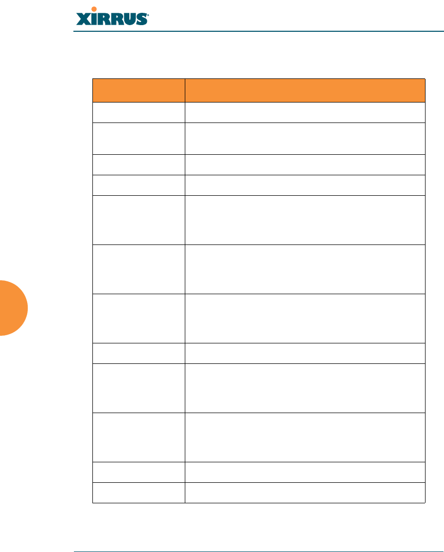
Wi-Fi Array
268 The Command Line Interface
file
The file command [Xirrus_Wi-Fi_Array(config-file)#] is used to manage files.
Command Description
active-image Validate and commit a new array software image.
backup-image Validate and commit a new backup software
image.
check-image Validate a new array software image.
chkdsk Check flash file system.
copy Copy a file to another file.
FORMAT:
file copy [sourcefile destinationfile]
dir List the contents of a directory.
FORMAT:
file dir [directory]
erase Delete a file from the FLASH file system.
FORMAT:
file erase [filename]
format Format flash file system.
ftp Open an FTP connection with a remote server.
FORMAT:
file ftp [ftpconnection]
list List the contents of a file.
FORMAT:
file list [filename]
rename Rename a file.
scp Copy a file to or from a remote system.

Wi-Fi Array
The Command Line Interface 269
filter
The filter command [Xirrus_Wi-Fi_Array(config-filter)#] is used to manage
protocol filters and filter lists.
Command Description
add Add a filter.
FORMAT:
filter add [name]
add-list Add a filter list.
FORMAT:
filter add-list [name]
del Delete a filter.
FORMAT:
filter del [name]
del-list Delete a filter list.
FORMAT:
filter del-list [name]
edit Edit a filter.
FORMAT:
filter edit [name type]
edit-list Edit a filter list
FORMAT:
filter edit-list [name type]
enable Enable a filter list.
FORMAT:
filter enable
move Change a filter priority.
FORMAT:
filter move [name priority]