Cambium Networks XN12 Wireless LAN Array User Manual XN PDF
Xirrus, Inc. Wireless LAN Array XN PDF
Contents
- 1. Users Manual 1of5
- 2. Users Manual 2of5
- 3. Users Manual 3of5
- 4. Users Manual 4of5
- 5. Users Manual 5of5
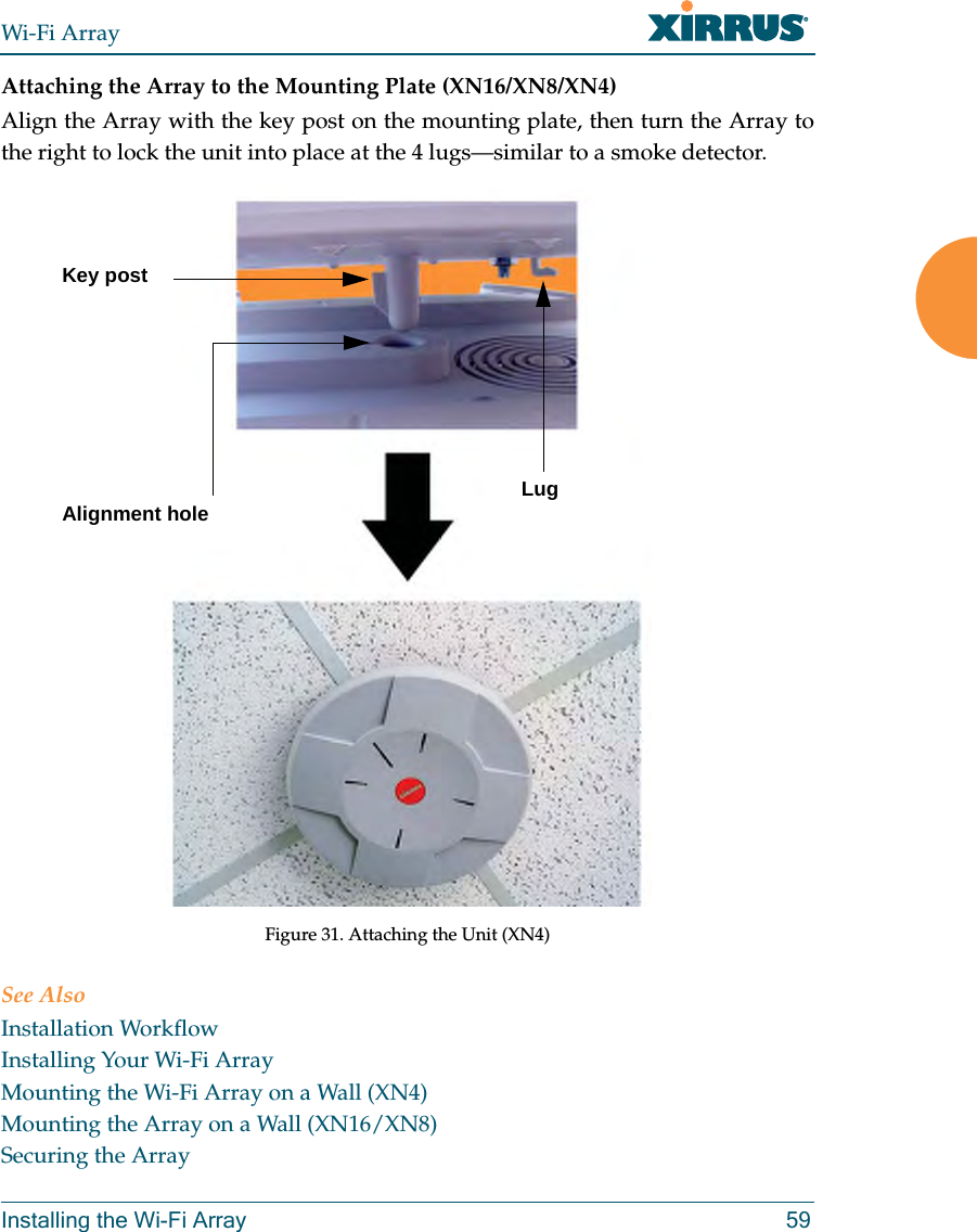
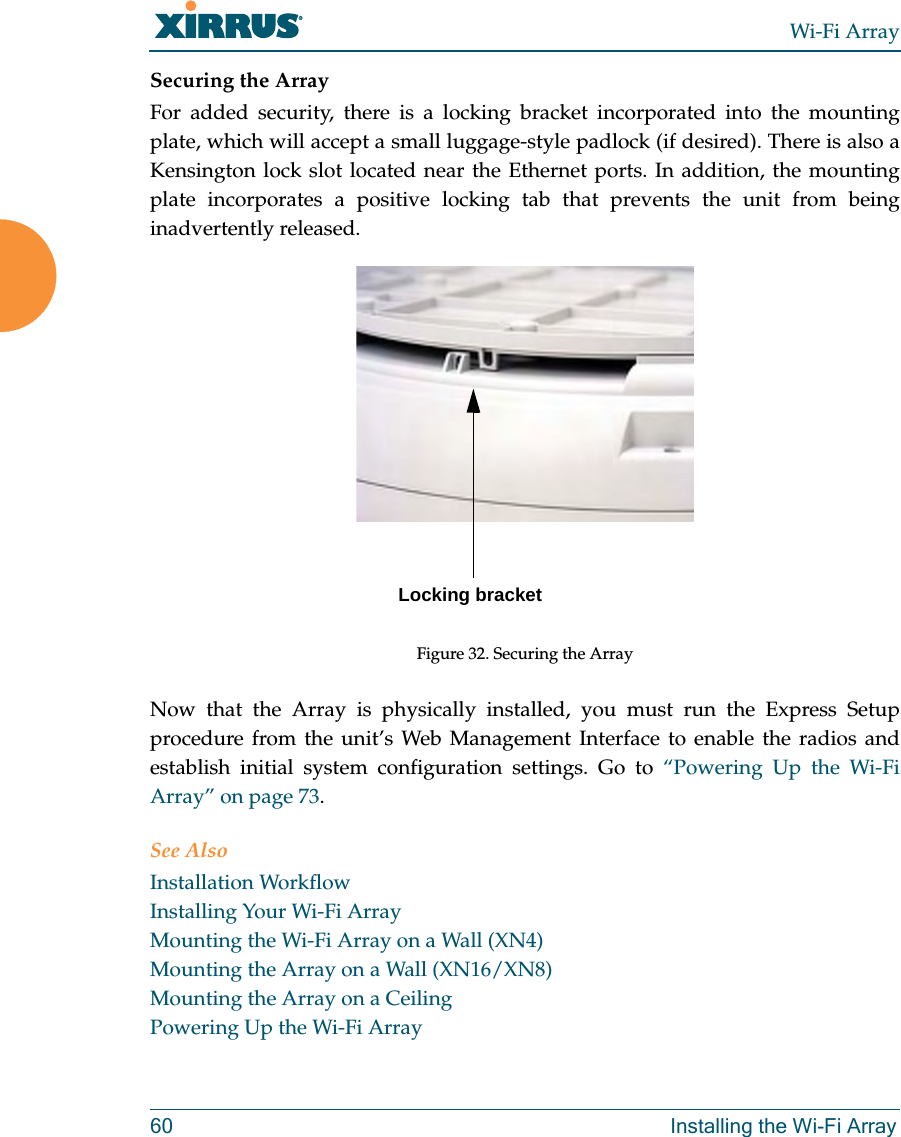
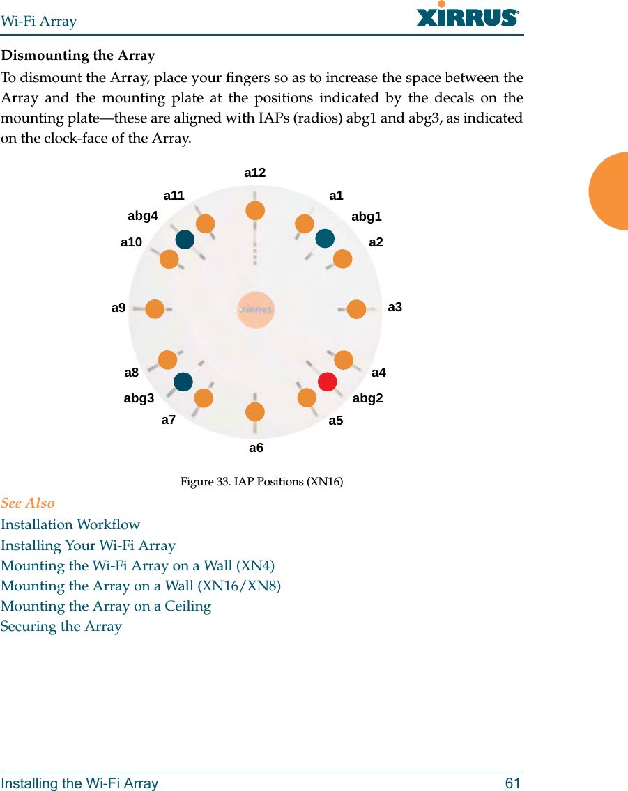
- 6. A Pages 1 to 125 from ArrayGuide Rel4 SS Dec02 2008
- 7. B Pages 126 to 225 from ArrayGuide Rel 4 SS Dec02 2008
- 8. C Pages 226 to 350 from ArrayGuide Rel4 SS Dec02 2008
- 9. D Pages 351 to 496 from ArrayGuide Rel4 SS Dec02 2008 Small 5
- 10. XN Guide small 1 of 5 revised
Users Manual 1of5
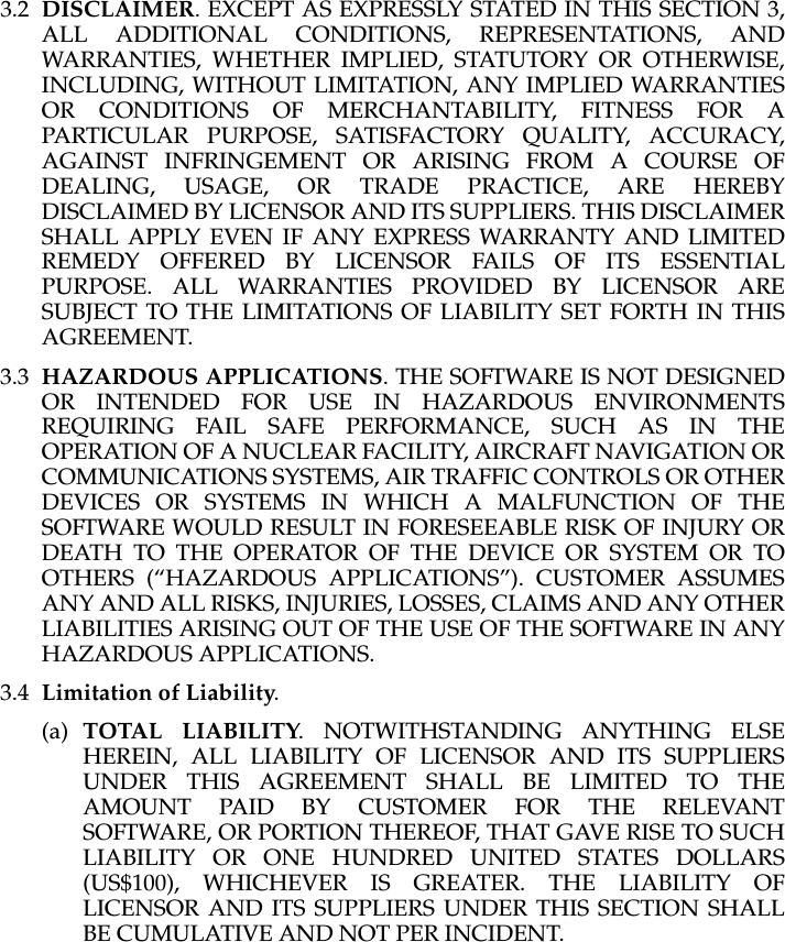
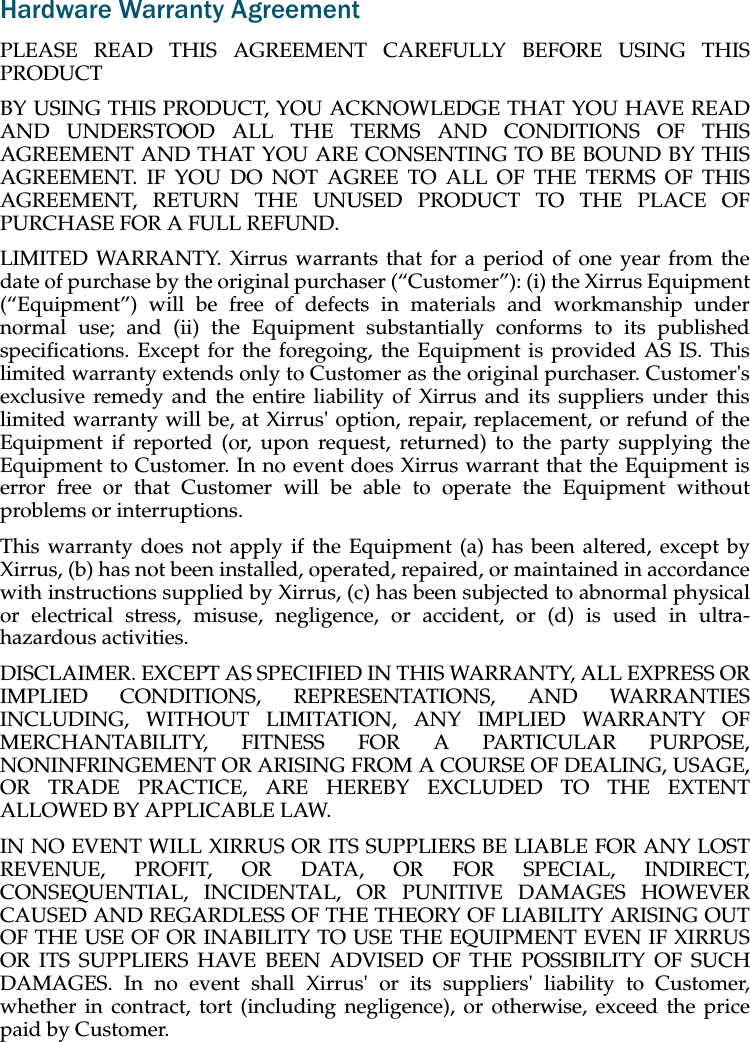
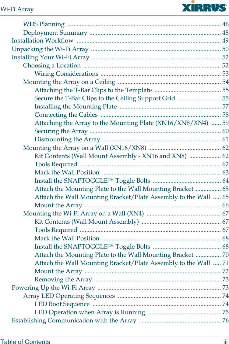
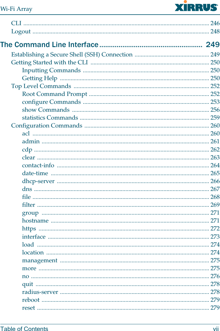
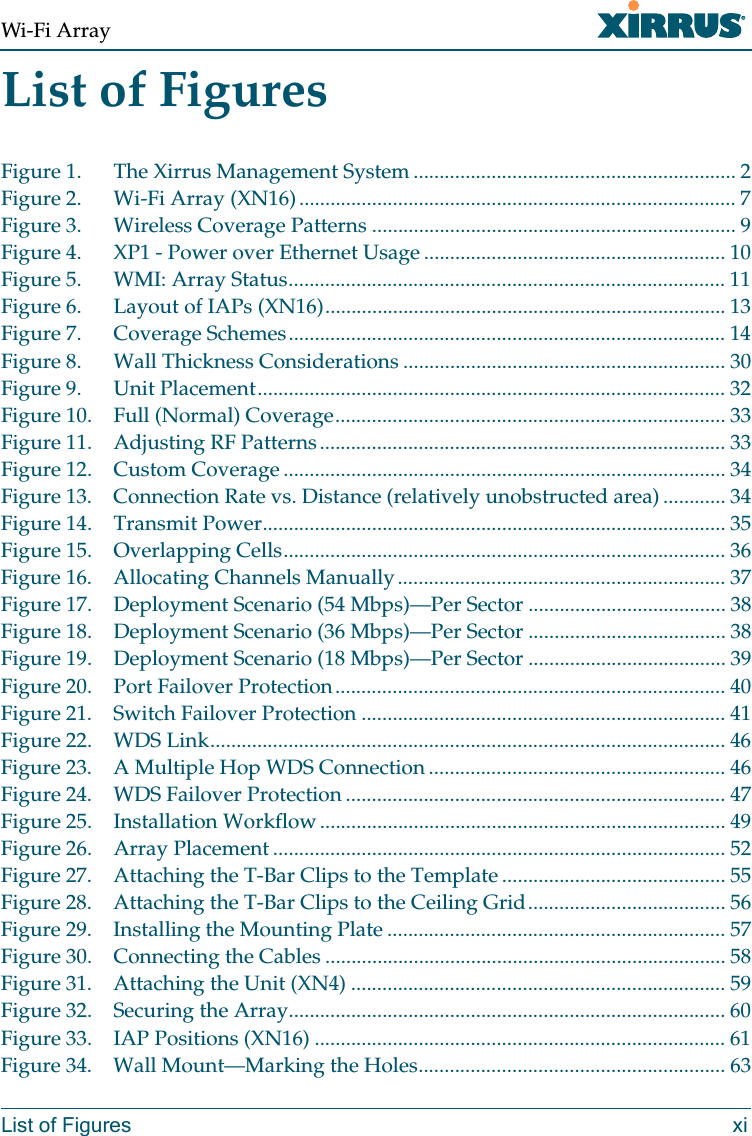
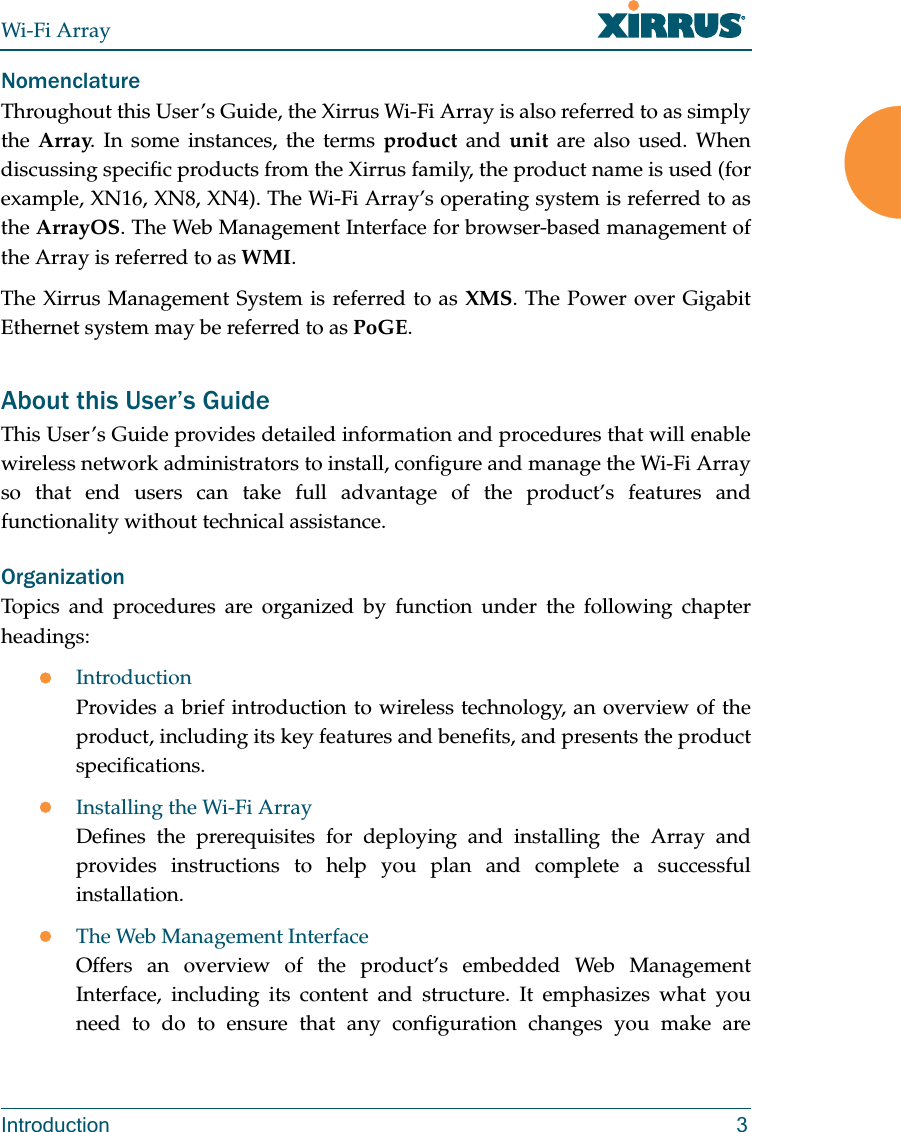
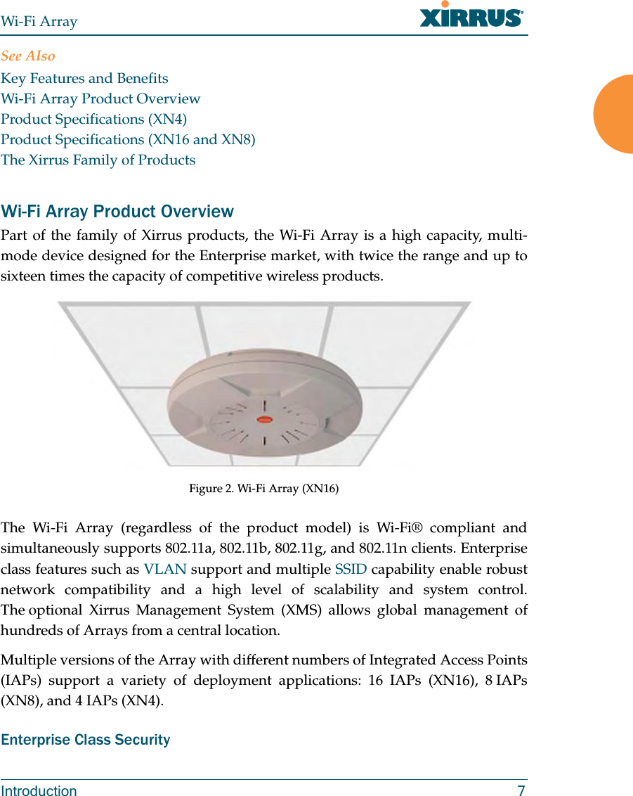
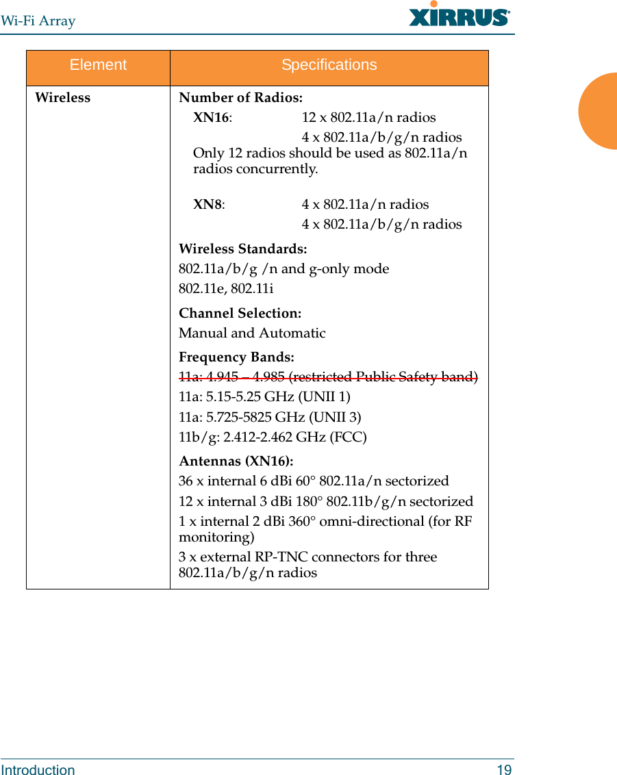
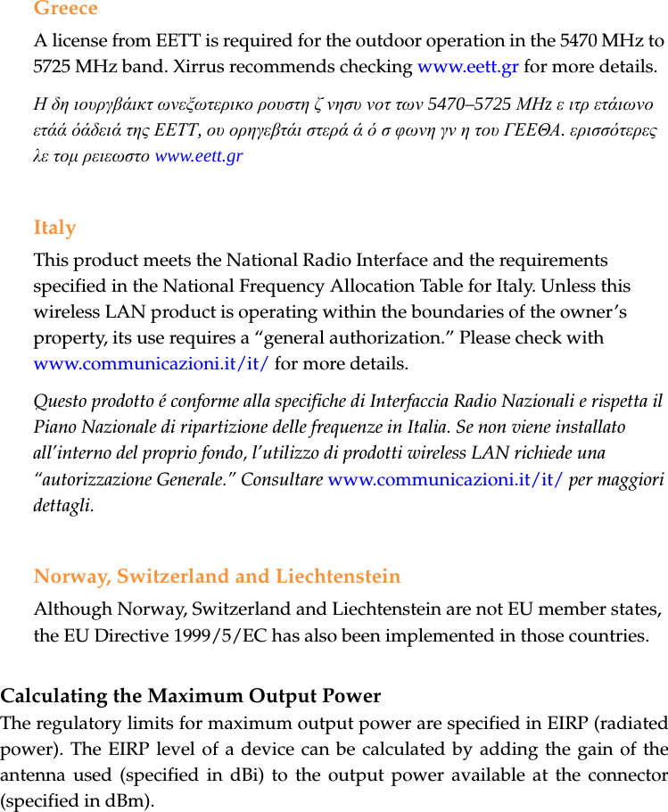
![EU Directive 1999/5/EC Compliance InformationThis section contains compliance information for the Xirrus Wi-Fi Array family of products, which includes the XN16, XN8, and XN4. The compliance information contained in this section is relevant to the European Union and other countries that have implemented the EU Directive 1999/5/EC.Declaration of ConformityCesky [Czech] Toto zahzeni je v souladu se základnimi požadavky a ostatnimi odpovidajcimi ustano veni mi Směrnice 1999/5/EC.Dansk [Danish] Dette udstyr er i overensstemmelse med de væsentlige krav og andre relevante bestemmelser i Direktiv 1999/5/EF.Deutsch [German] Dieses Gerat entspricht den grundlegenden Anforderungen und den weiteren entsprechenden Vorgaben der Richtinie 1999/5/EU.Eesti [Estonian] See seande vastab direktiivi 1999/5/EU olulistele nöuetele ja teistele as jakohastele sätetele.English This equipment is in compliance with the essential requirements and other relevant provisions of Directive 1999/5/EC.Español [Spain] Este equipo cump le con los requisitos esenciales asi como con otras disposiciones de la Directiva 1999/5/CE.Ελληνυκη [Greek] Αυτόζ ο εξοπλτσμόζ είναι σε συμμόρφωση με τιζ ουσιώδειζ απαιτήσειζ και ύλλεζ σχετικέζ διατάξειζ τηζ Οδηγιαζ 1999/5/EC.Français [French] Cet appareil est conforme aux exigences essentielles et aux autres dispositions pertinentes de la Directive 1999/5/EC.ĺslenska [Icelandic] Þetta tæki er samkvæmt grunnkröfum og öðrum viðeigandi ákvæðum Tilskipunar 1999/5/EC.](https://usermanual.wiki/Cambium-Networks/XN12.Users-Manual-1of5/User-Guide-1024227-Page-7.png)
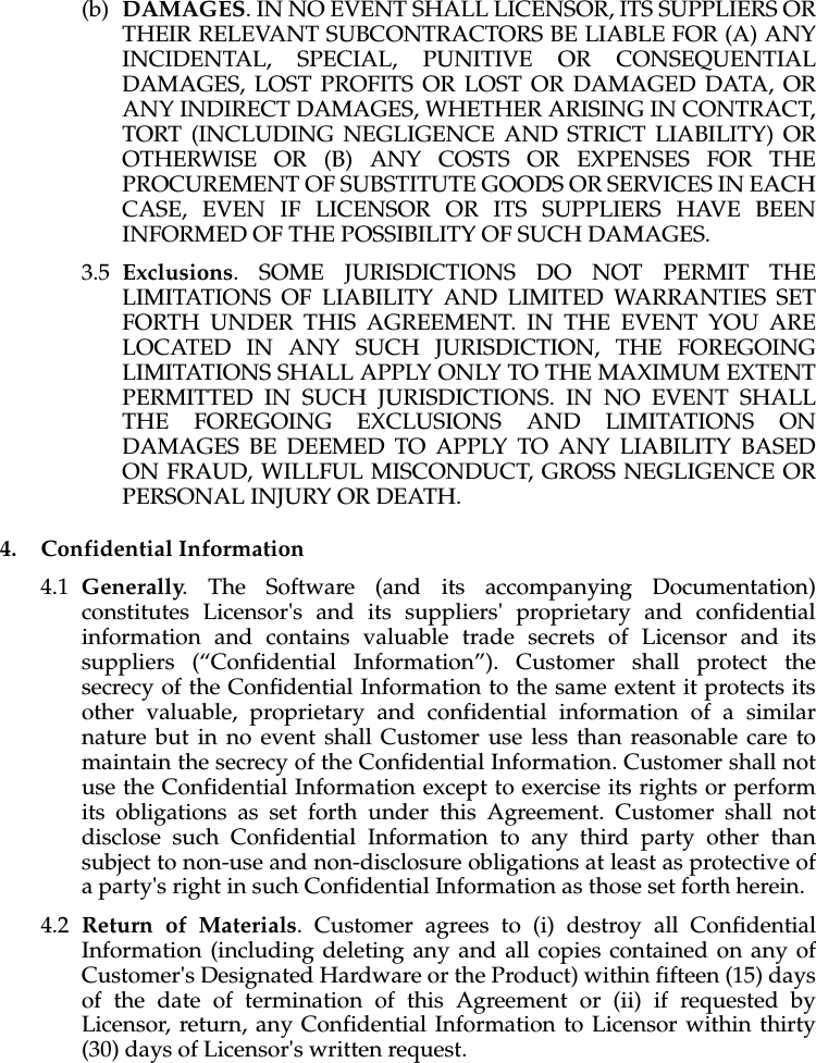
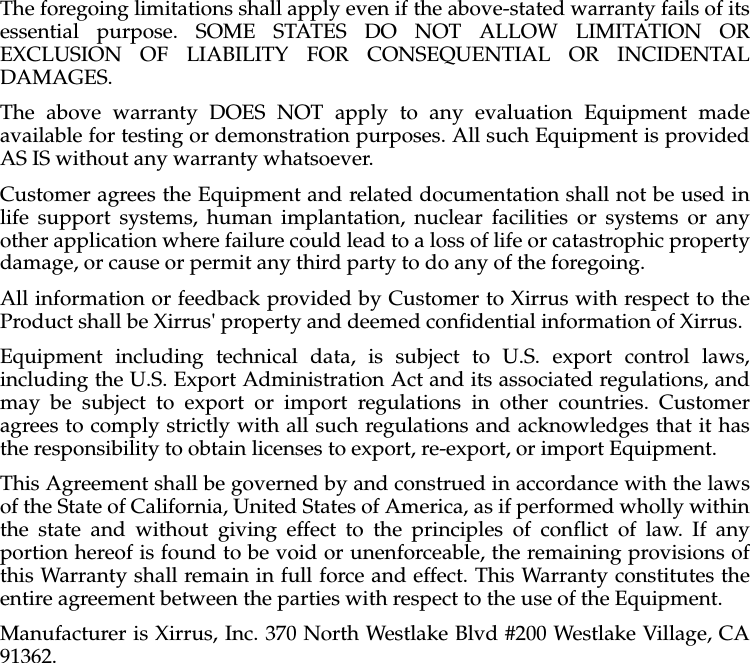
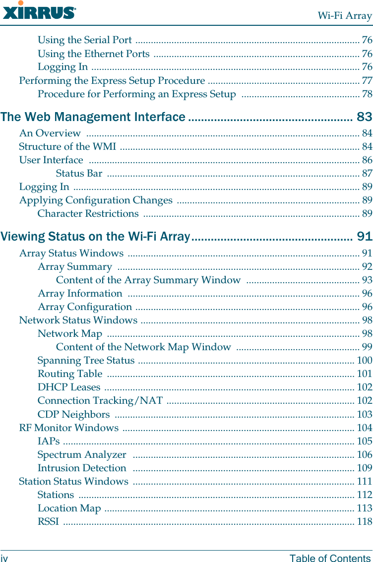
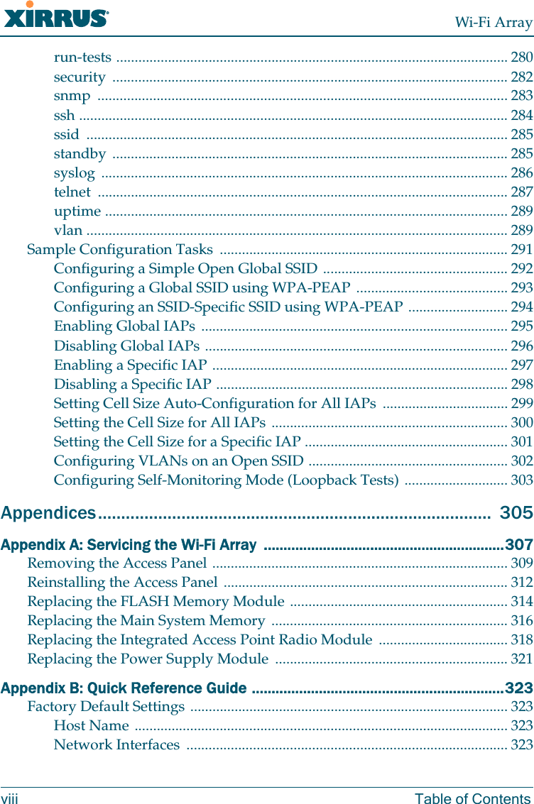
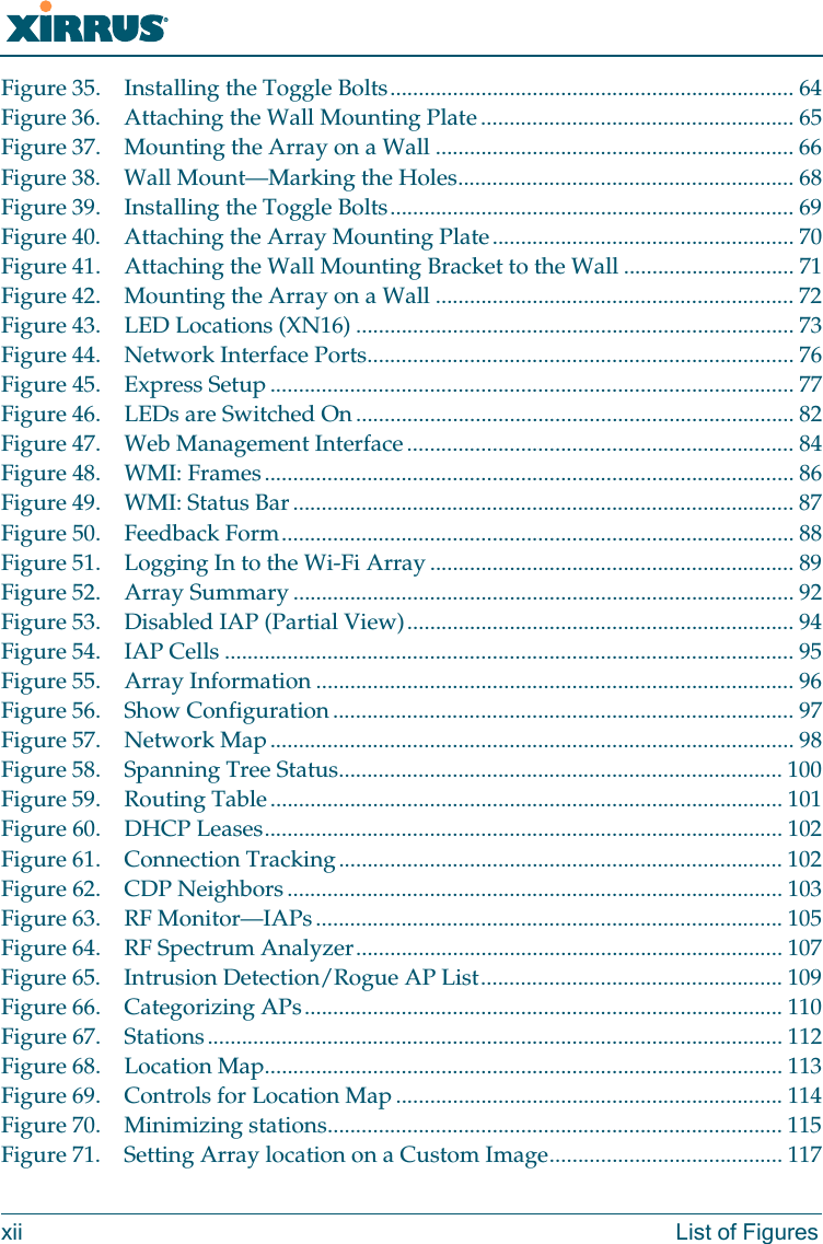
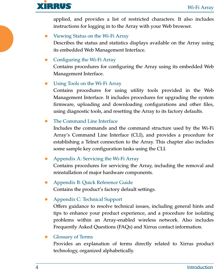
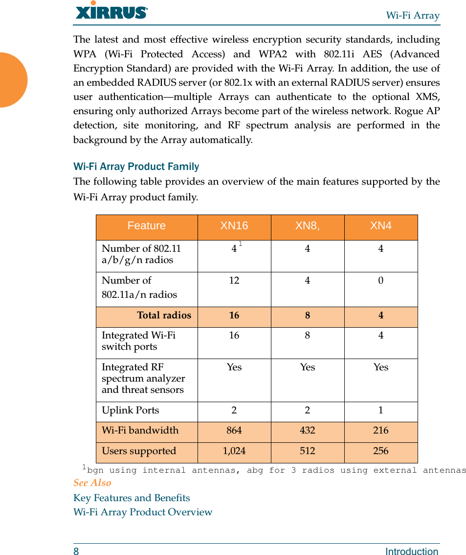
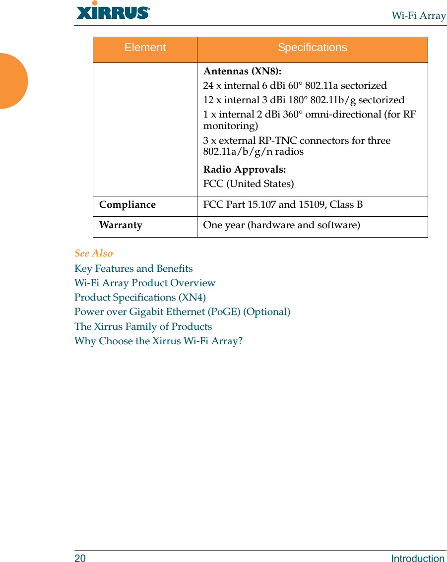
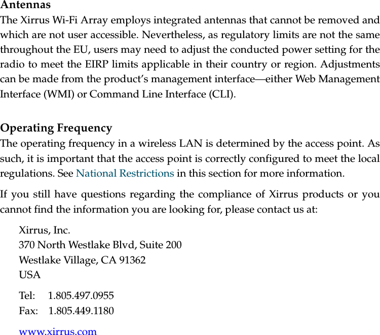
![Italiano [Italian] Questo apparato é conforme ai requisiti essenziali ed agli altri principi sanciti dalla Direttiva 1999/5/CE.Latviski [Latvian] Šī iekārta atbilst Direktīvas 1999/5/EK būtiskajāprasībām un citiem ar to saistītajiem noteikumiem.Lietuvių [Lithuanian] Šis įrenginys tenkina 1995/5/EB Direktyvos esminius reikalavimus ir kitas šios direktyvos nuostatas.Nederlands [Dutch] Dit apparant voldoet aan de essentiele eisen en andere van toepassing zijnde bepalingen van de Richtlijn 1995/5/EC.Malti [Maltese] Dan l-apparant huwa konformi mal-htigiet essenzjali u l-provedimenti l-ohra rilevanti tad-Direttiva 1999/5/EC.Margyar [Hungarian] Ez a készülék teljesiti az alapvetö követelményeket és más 1999/5/EK irányelvben meghatározott vonatkozó rendelkezéseket.Norsk [Norwegian] Dette utstyret er i samsvar med de grunnleggende krav og andre relevante bestemmelser i EU-direktiv 1999/5/EF.Polski [Polish] Urządzenie jest zgodne z ogólnymi wymaganiami oraz sczególnymi mi warunkami określony mi Dyrektywą. UE:1999/5/EC.Portuguès [Portugese] Este equipamento está em conformidade com os requisitos essenciais e outras provisões relevantes da Directiva 1999/5/EC.Slovensko [Slovenian] Ta naprava je skladna z bistvenimi zahtevami in ostalimi relevantnimi popoji Direktive 1999/5/EC.Slovensky [Slovak] Toto zariadenie je v zhode so základnými požadavkami a inými prislušnými nariadeniami direktiv: 1999/5/EC.](https://usermanual.wiki/Cambium-Networks/XN12.Users-Manual-1of5/User-Guide-1024227-Page-8.png)
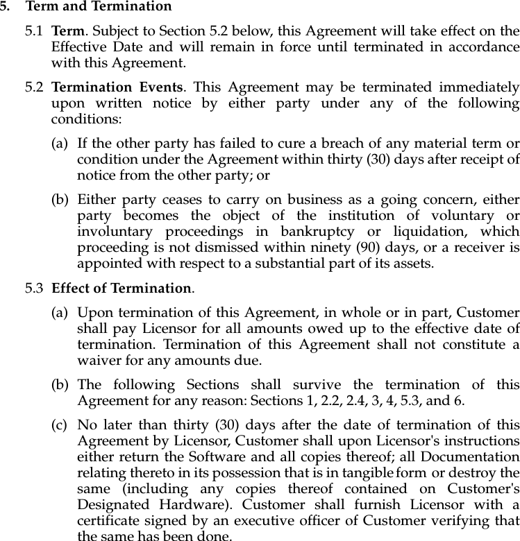
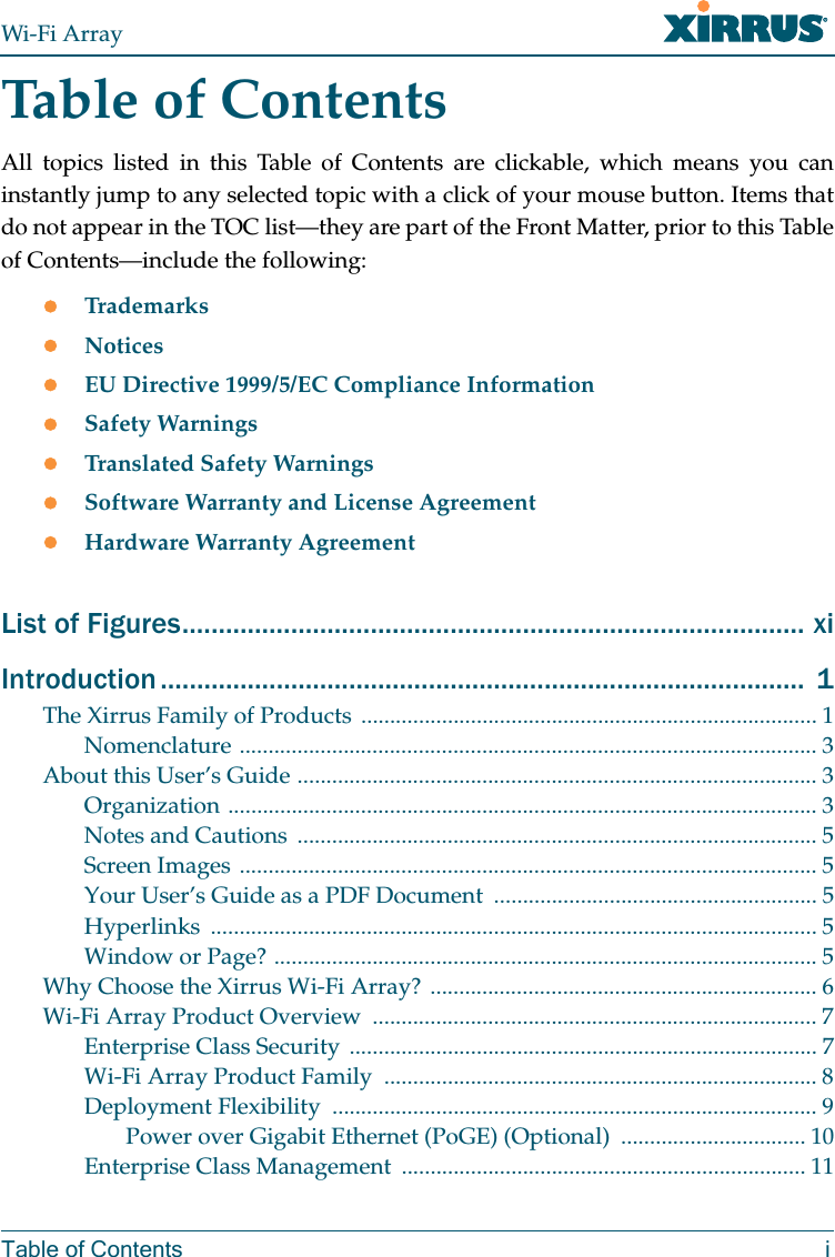
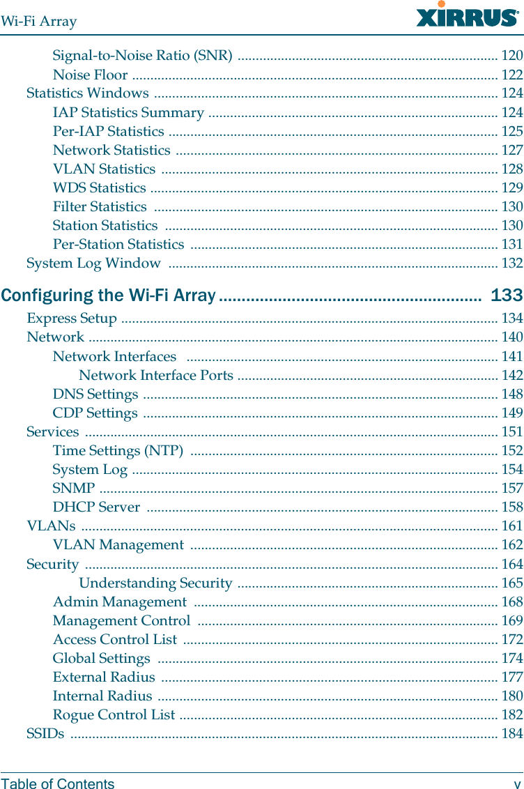
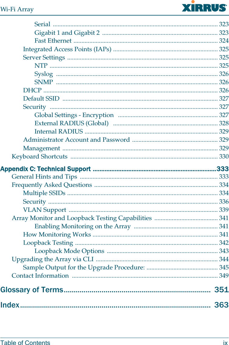
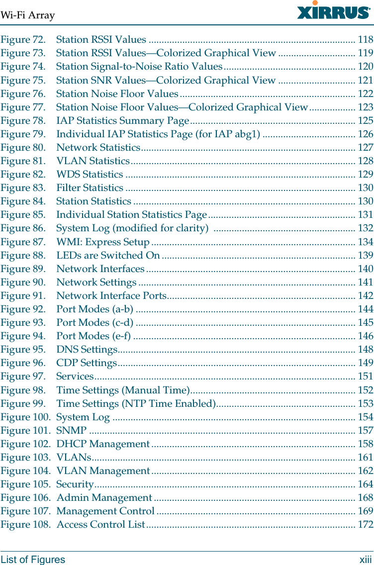
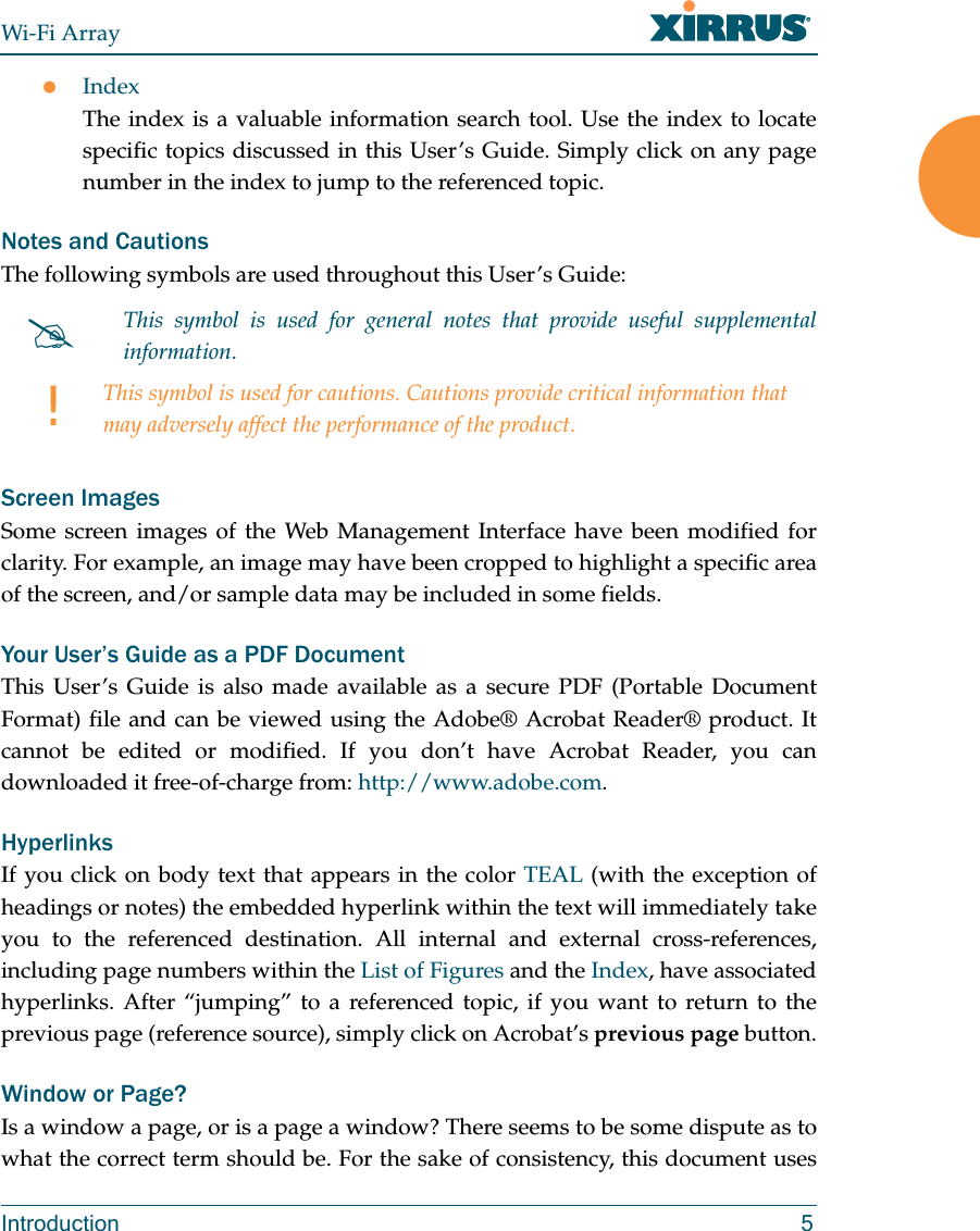
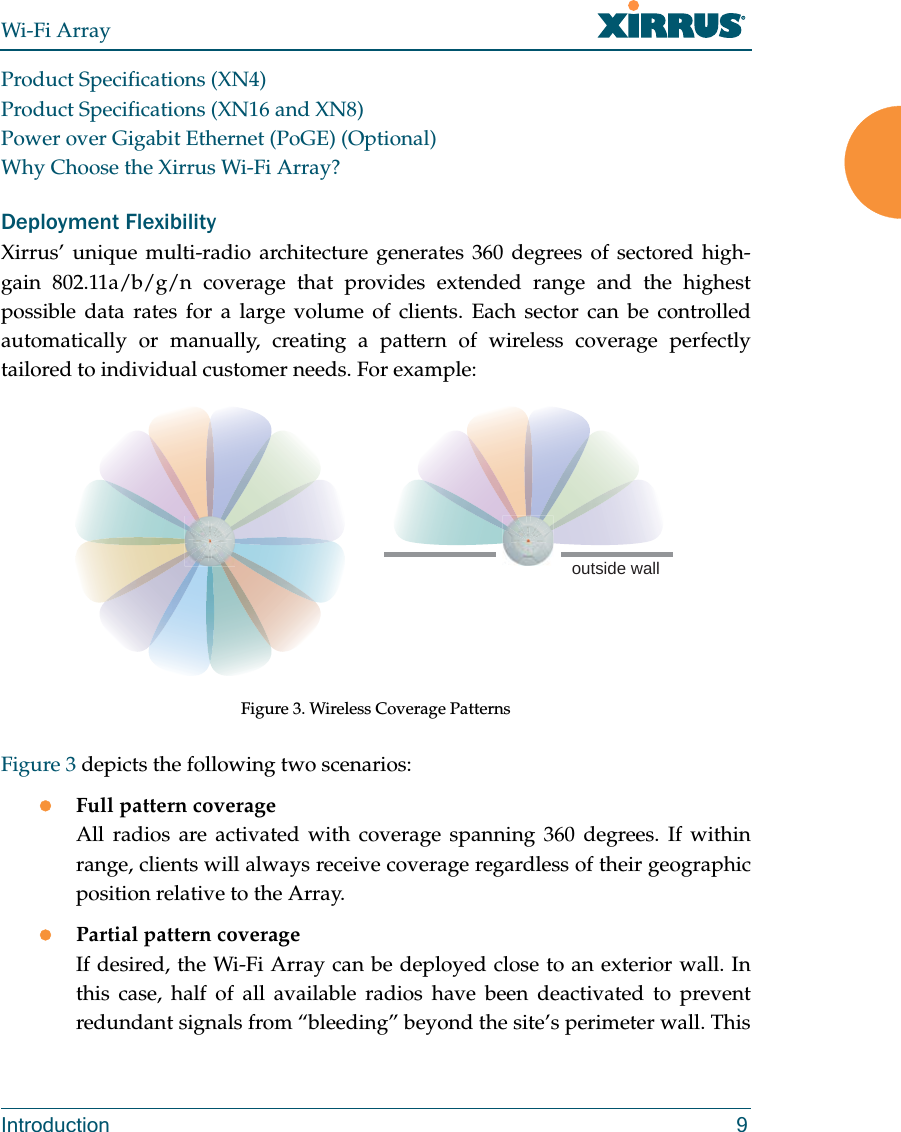
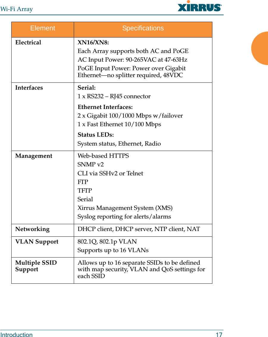
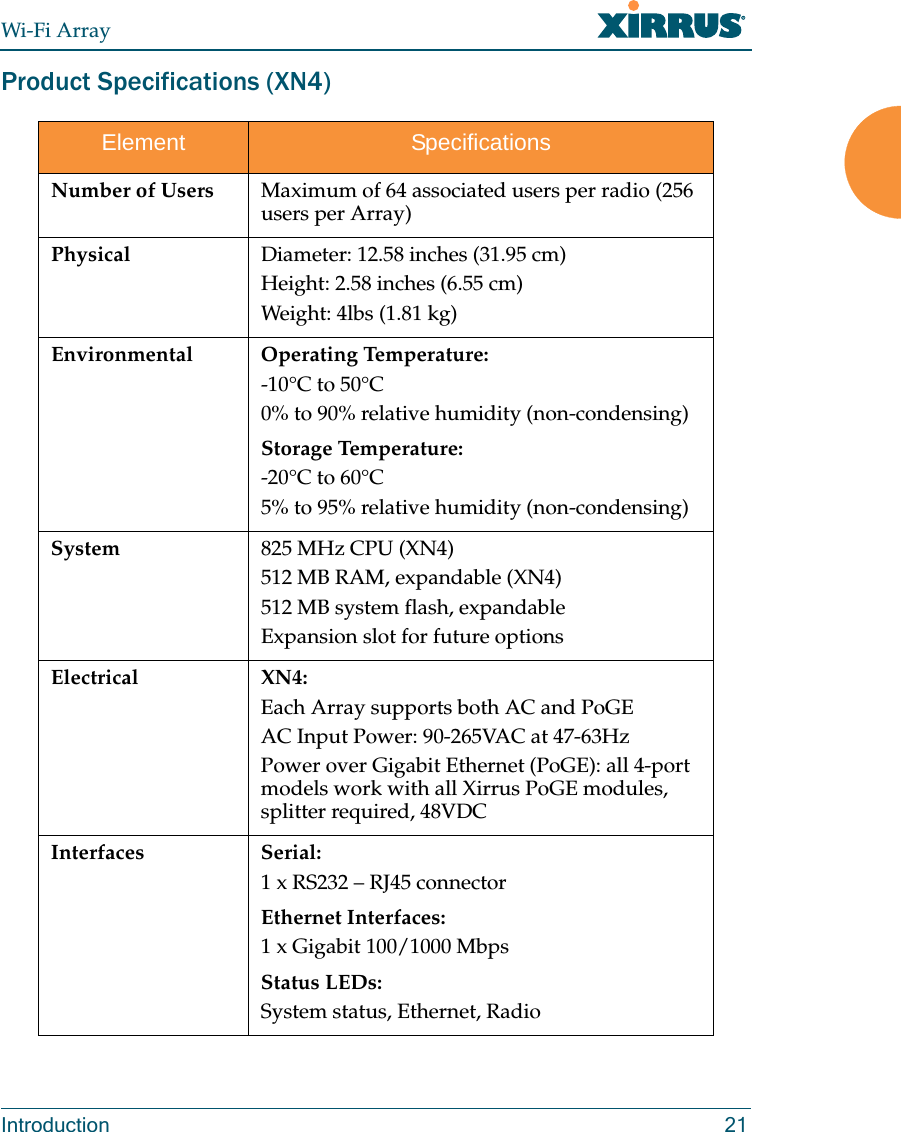
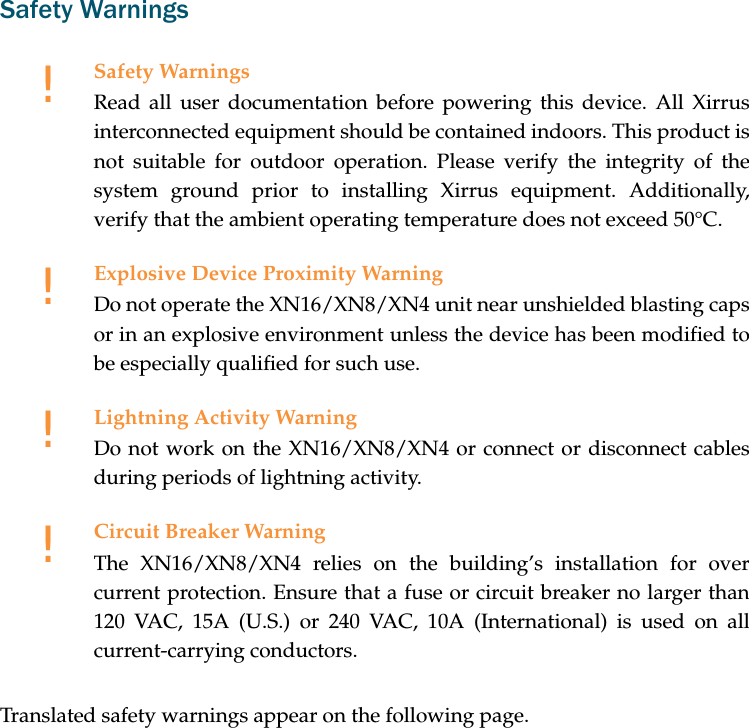
![Assessment CriteriaThe following standards were applied during the assessment of the product against the requirements of the Directive 1999/5/EC:zRadio: EN 301 893 and EN 300 328 (if applicable)zEMC: EN 301 489-1 and EN 301 489-17zSafety: EN 50371 to EN 50385 and EN 60601CE MarkingFor the Xirrus Wi-Fi Array (XN16, XN8, XN4), the CE mark and Class-2 identifier opposite are affixed to the equipment and its packaging: Suomi [Finnish] Tämä laite täyttää direktiivin 1999/5//EY olennaiset vaatimukset ja on siinä asetettujen muiden laitetta koskevien määräysten mukainen.Svenska [Swedish] Denna utrustning är i överensstämmelse med de väsentliga kraven och andra relevanta bestämmelser i Direktiv 1999/5/EC.](https://usermanual.wiki/Cambium-Networks/XN12.Users-Manual-1of5/User-Guide-1024227-Page-9.png)
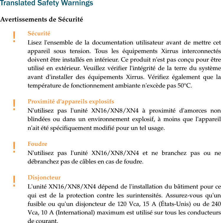
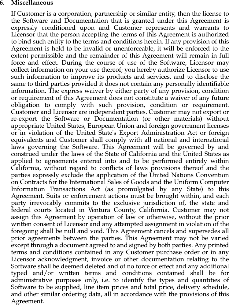
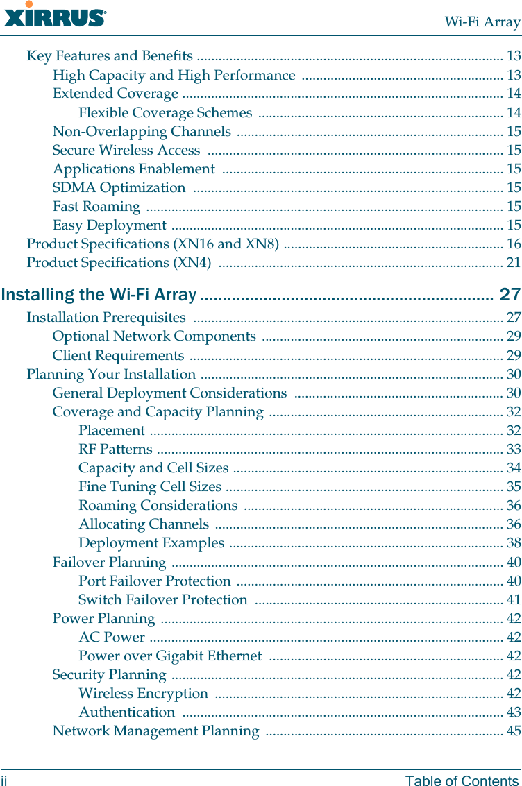
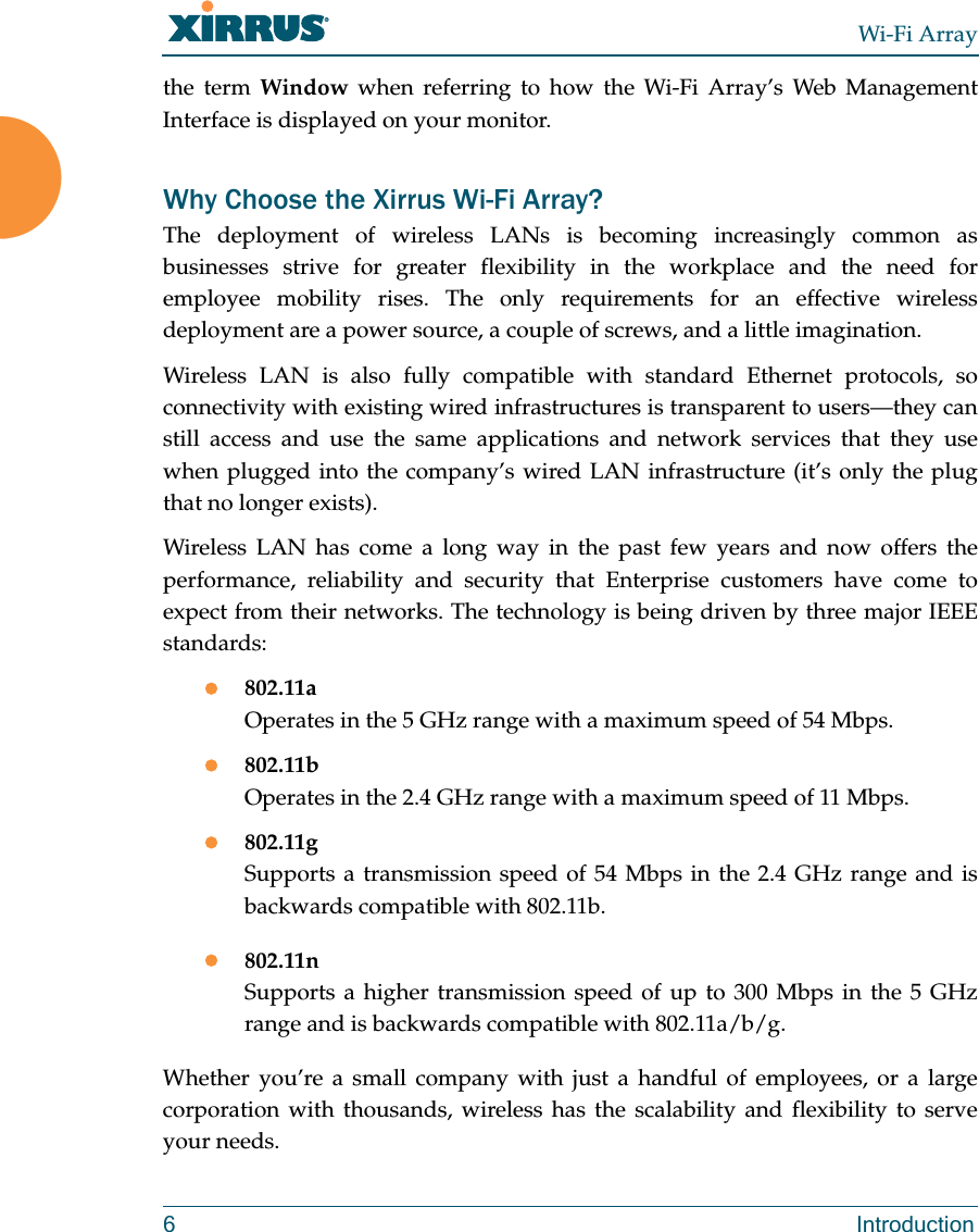
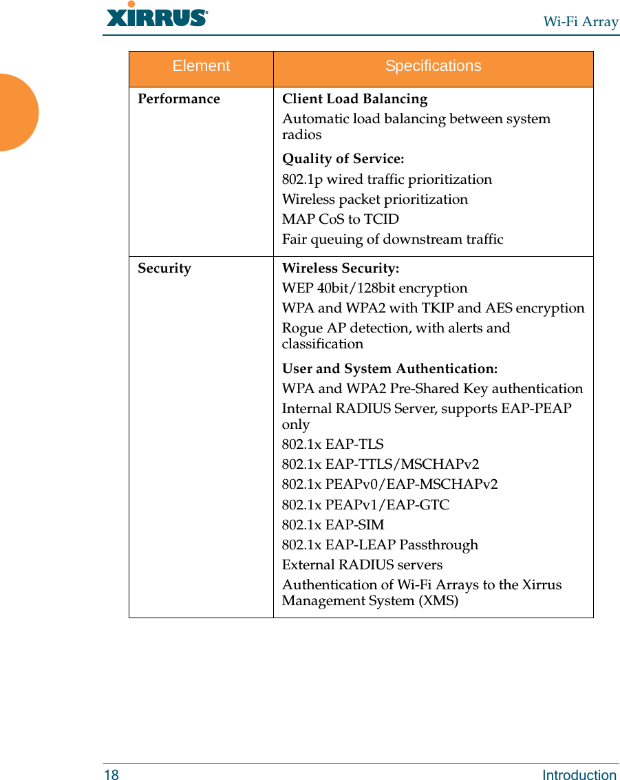
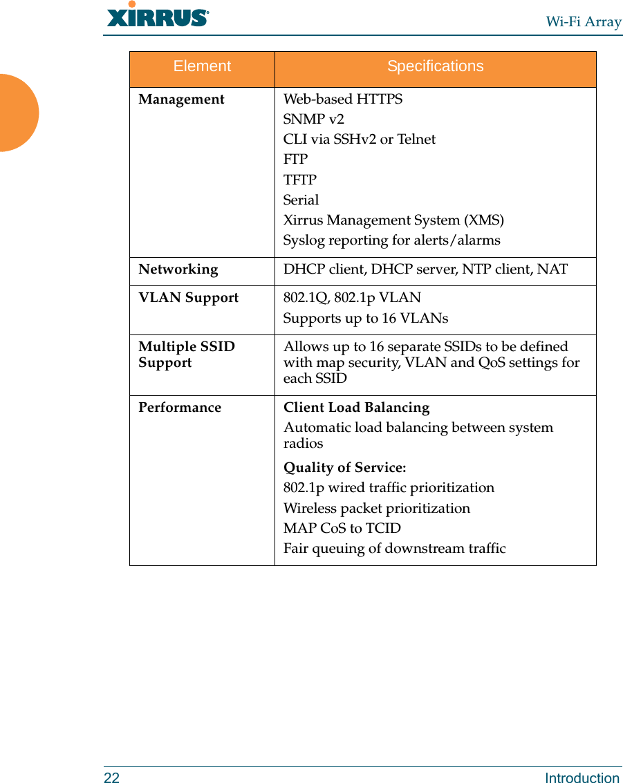
![2.4 Restrictions. Customer shall not itself, or through any parent, subsidiary, affiliate, agent or other third party (i) sell, rent, lease, license or sublicense, assign or otherwise transfer the Software, or any of Customer's rights and obligations under this Agreement except as expressly permitted herein; (ii) decompile, disassemble, or reverse engineer the Software, in whole or in part, provided that in those jurisdictions in which a total prohibition on any reverse engineering is prohibited as a matter of law and such prohibition is not cured by the fact that this Agreement is subject to the laws of the State of California, Licensor agrees to grant Customer, upon Customer's written request to Licensor, a limited reverse engineering license to permit interoperability of the Software with other software or code used by Customer; (iii) allow access to the Software by any user other than by Customer's employees and contractors who are bound in writing to confidentiality and non-use restrictions at least as protective as those set forth herein; (iv) except as expressly set forth herein, write or develop any derivative software or any other software program based upon the Software; or (v) use any computer software or hardware which is designated to defeat any copy protection or other use limiting device, including any device intended to limit the number of users or devices accessing the Product. 3. Limited Warranty and Limitation of Liability3.1 Limited Warranty & Exclusions. Licensor warrants that the Software will perform in substantial accordance with the specifications therefor set forth in the Documentation for a period of ninety [90] days after Customer's acceptance of the terms of this Agreement with respect to the Software (“Warranty Period”). If during the Warranty Period the Software does not perform as warranted, Licensor shall, at its option, correct the relevant Software giving rise to such breach of performance or replace such Software free of charge. THE FOREGOING ARE CUSTOMER'S SOLE AND EXCLUSIVE REMEDIES FOR BREACH OF THE FOREGOING WARRANTY. THE WARRANTY SET FORTH ABOVE IS MADE TO AND FOR THE BENEFIT OF CUSTOMER ONLY. The warranty will apply only if (i) the Software has been used at all times and in accordance with the instructions for use set forth in the Documentation and this Agreement; (ii) no modification, alteration or addition has been made to the Software by persons other than Licensor or Licensor's authorized representative; and (iii) the Software or Product on which the Software is installed has not been subject to any unusual electrical charge.](https://usermanual.wiki/Cambium-Networks/XN12.Users-Manual-1of5/User-Guide-1024227-Page-18.png)