Cambium Networks XN12 WIRELESS LAN ARRAY User Manual
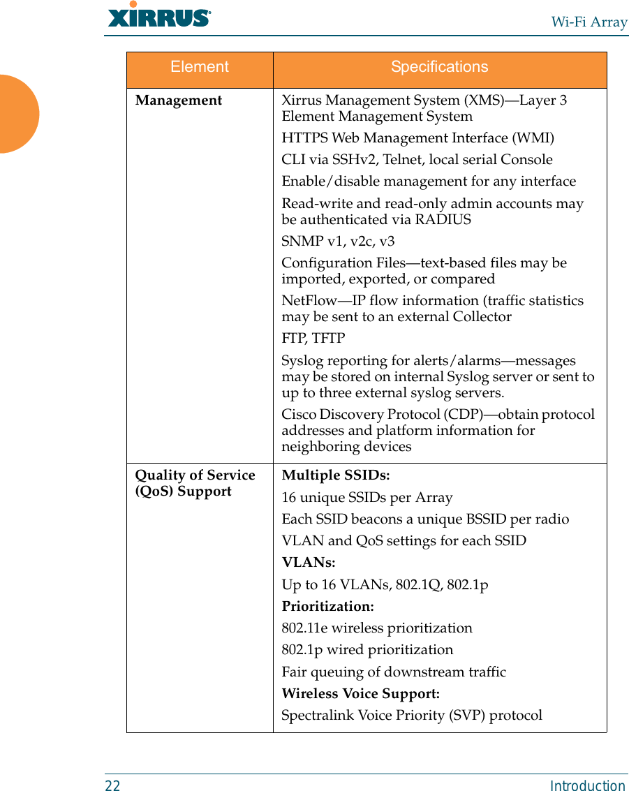
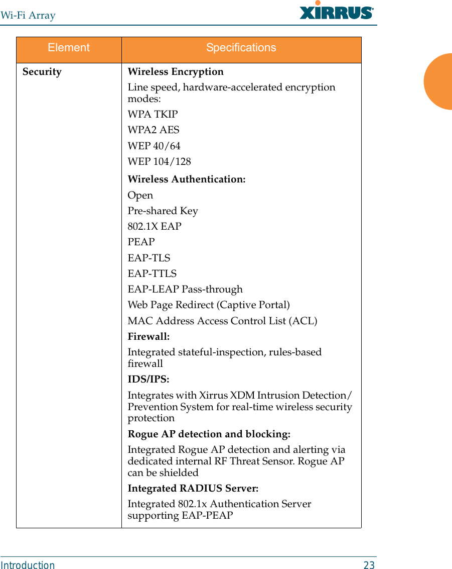
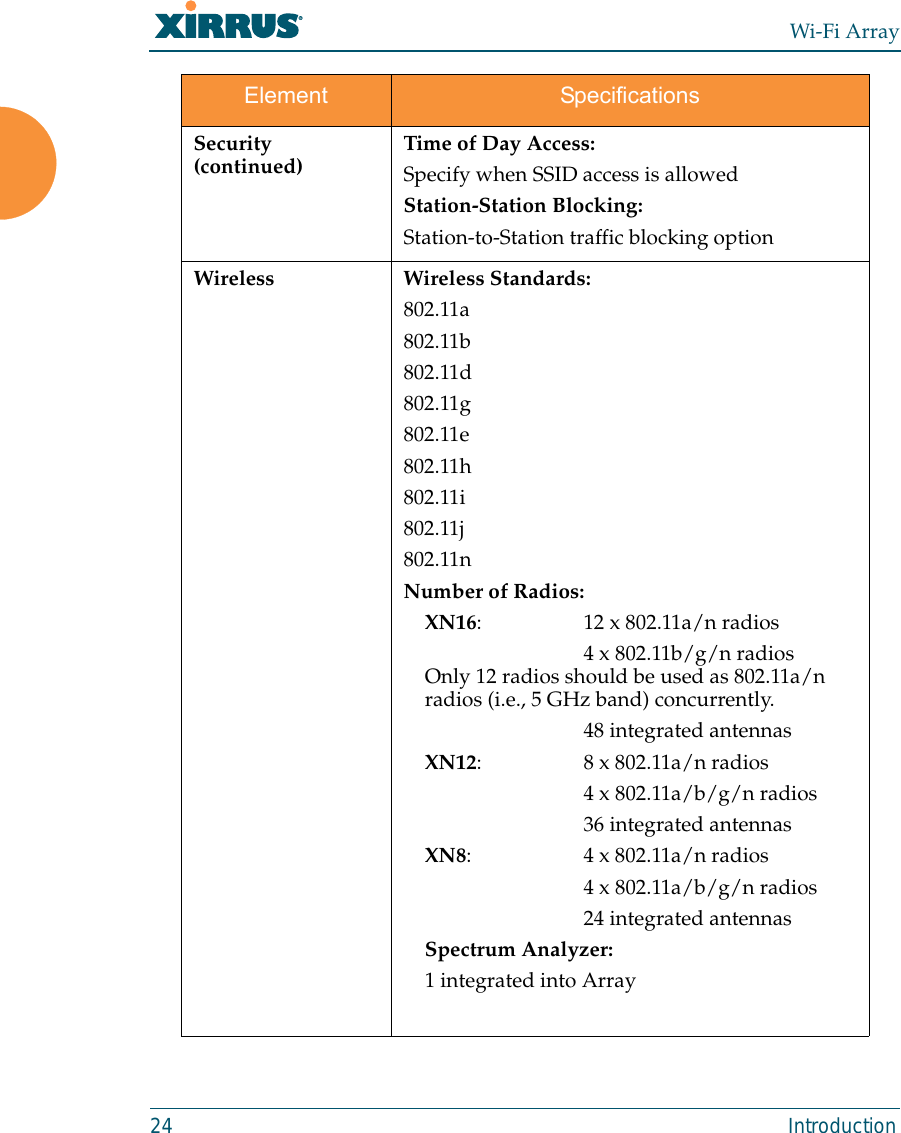
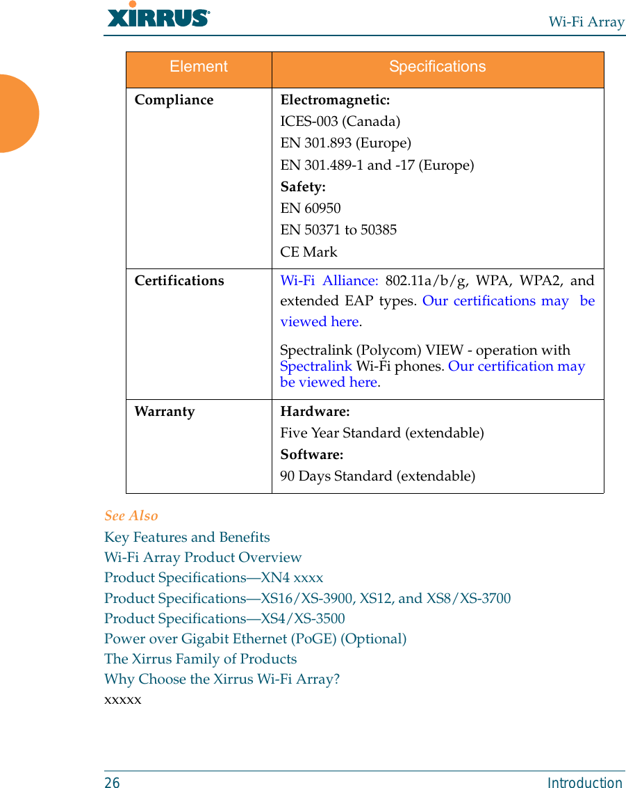
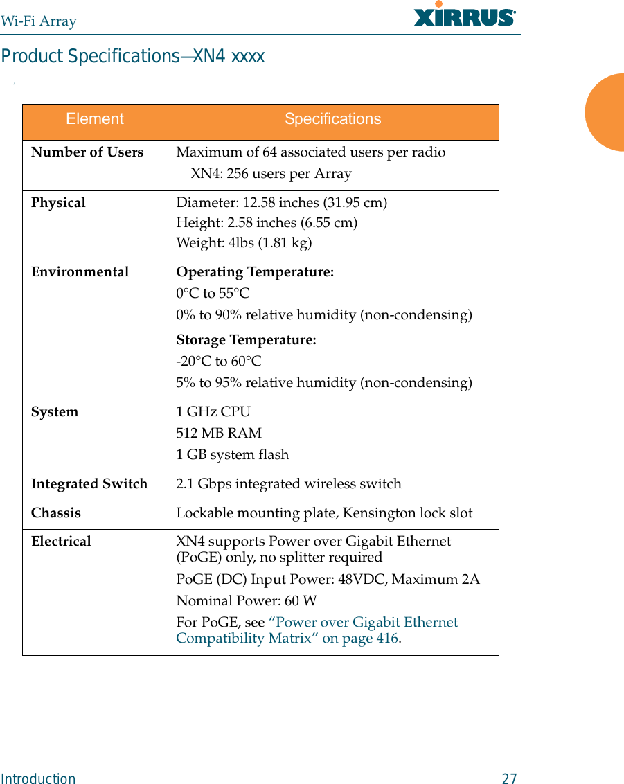
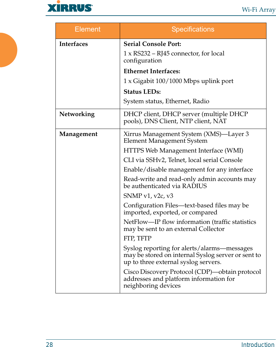
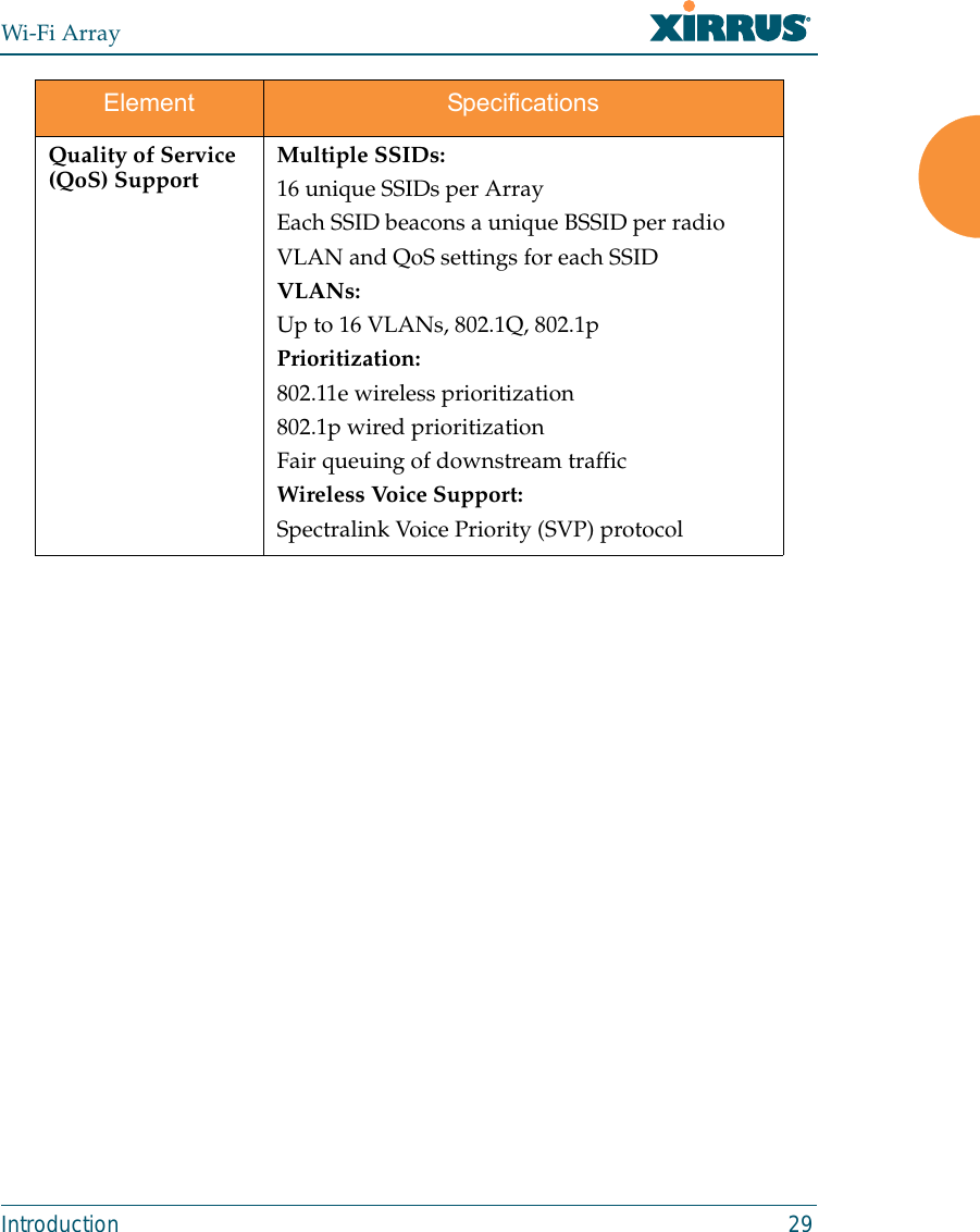
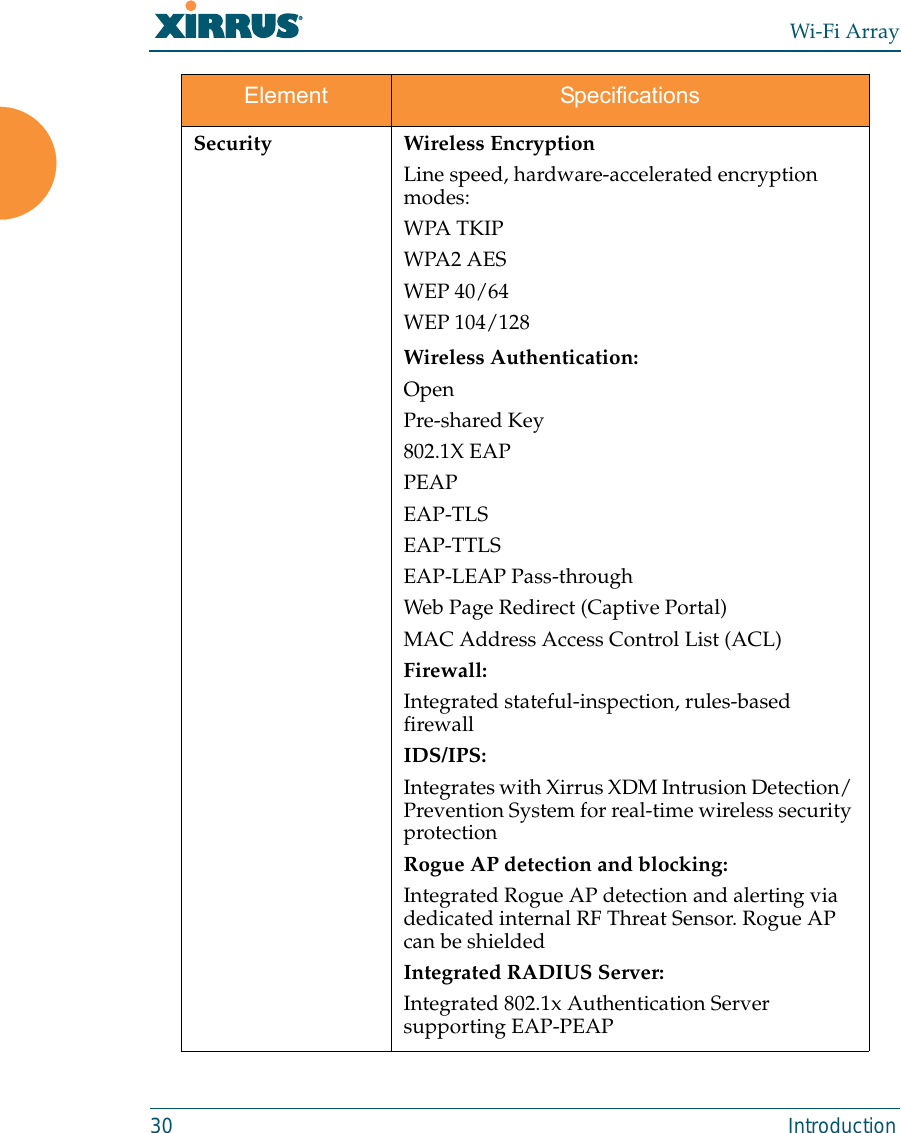
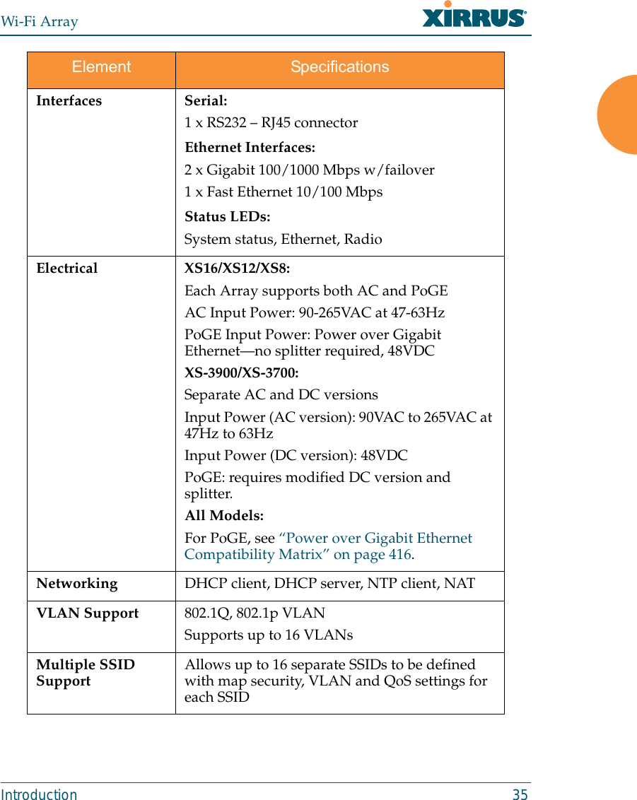
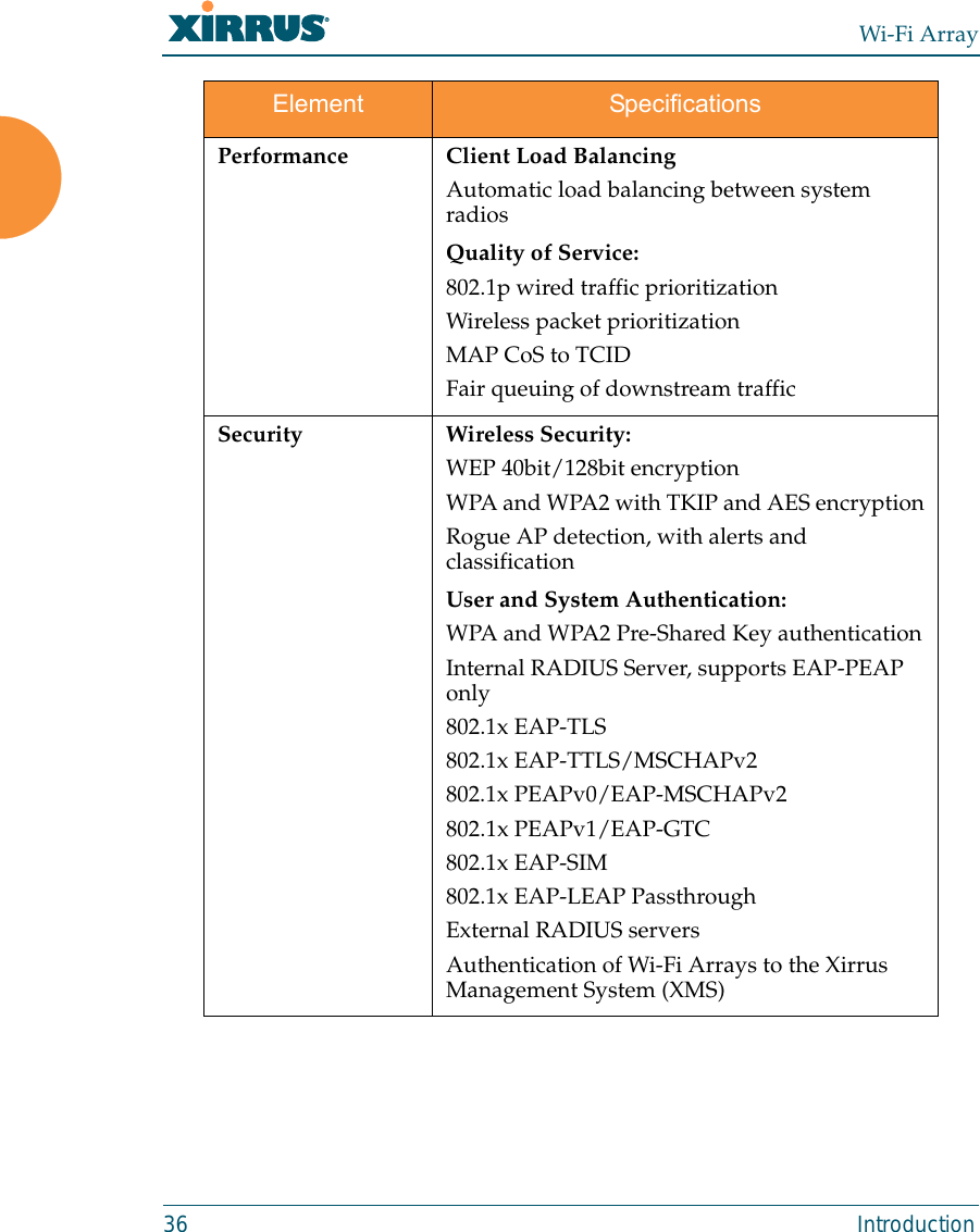
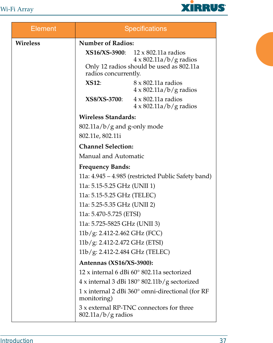
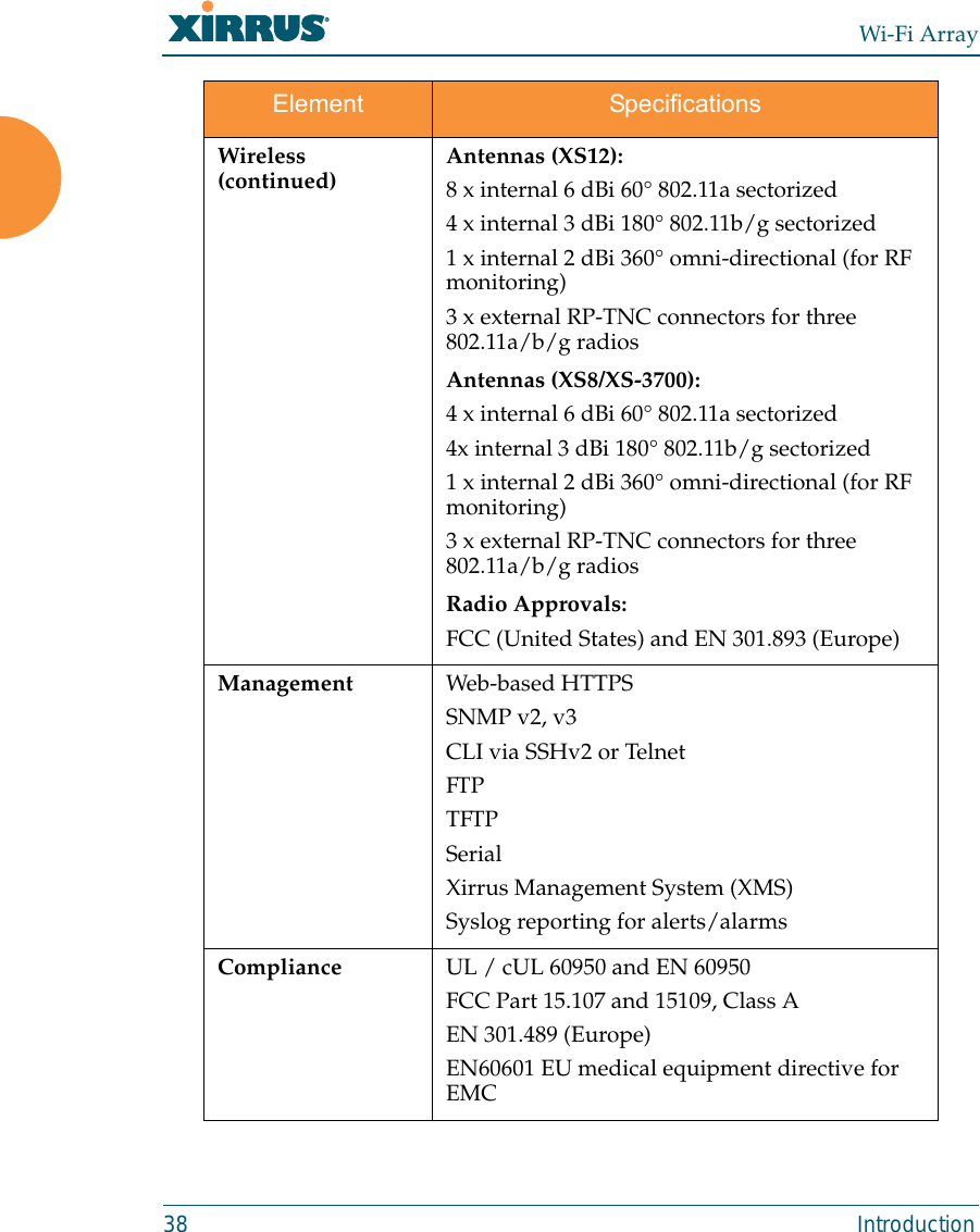
Xirrus, Inc. WIRELESS LAN ARRAY
Contents
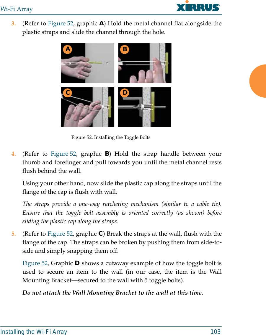
- 1. Users Manual 1of5
- 2. Users Manual 2of5
- 3. Users Manual 3of5
- 4. Users Manual 4of5
- 5. Users Manual 5of5
- 6. A Pages 1 to 125 from ArrayGuide Rel4 SS Dec02 2008
- 7. B Pages 126 to 225 from ArrayGuide Rel 4 SS Dec02 2008
- 8. C Pages 226 to 350 from ArrayGuide Rel4 SS Dec02 2008
- 9. D Pages 351 to 496 from ArrayGuide Rel4 SS Dec02 2008 Small 5
- 10. XN Guide small 1 of 5 revised
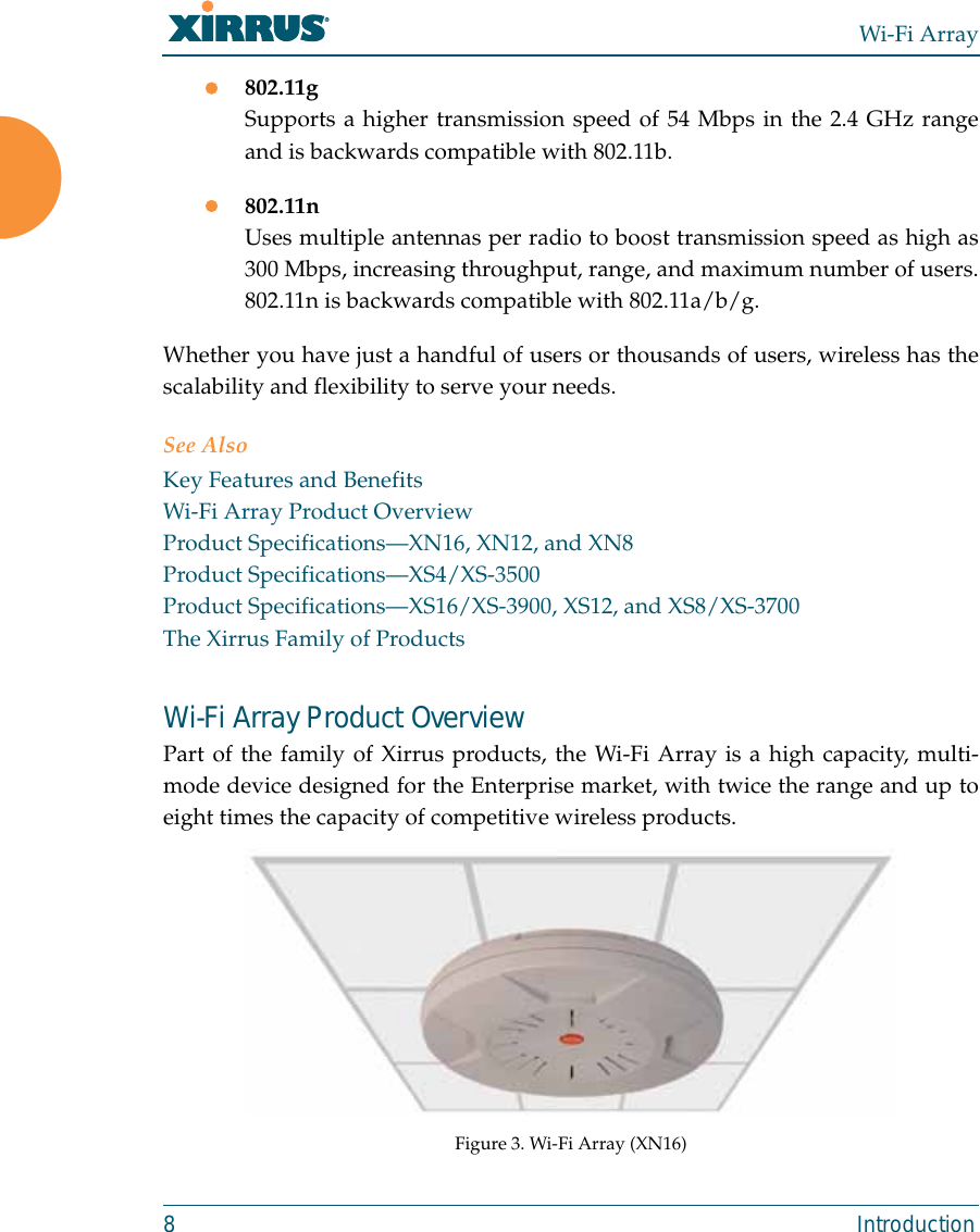
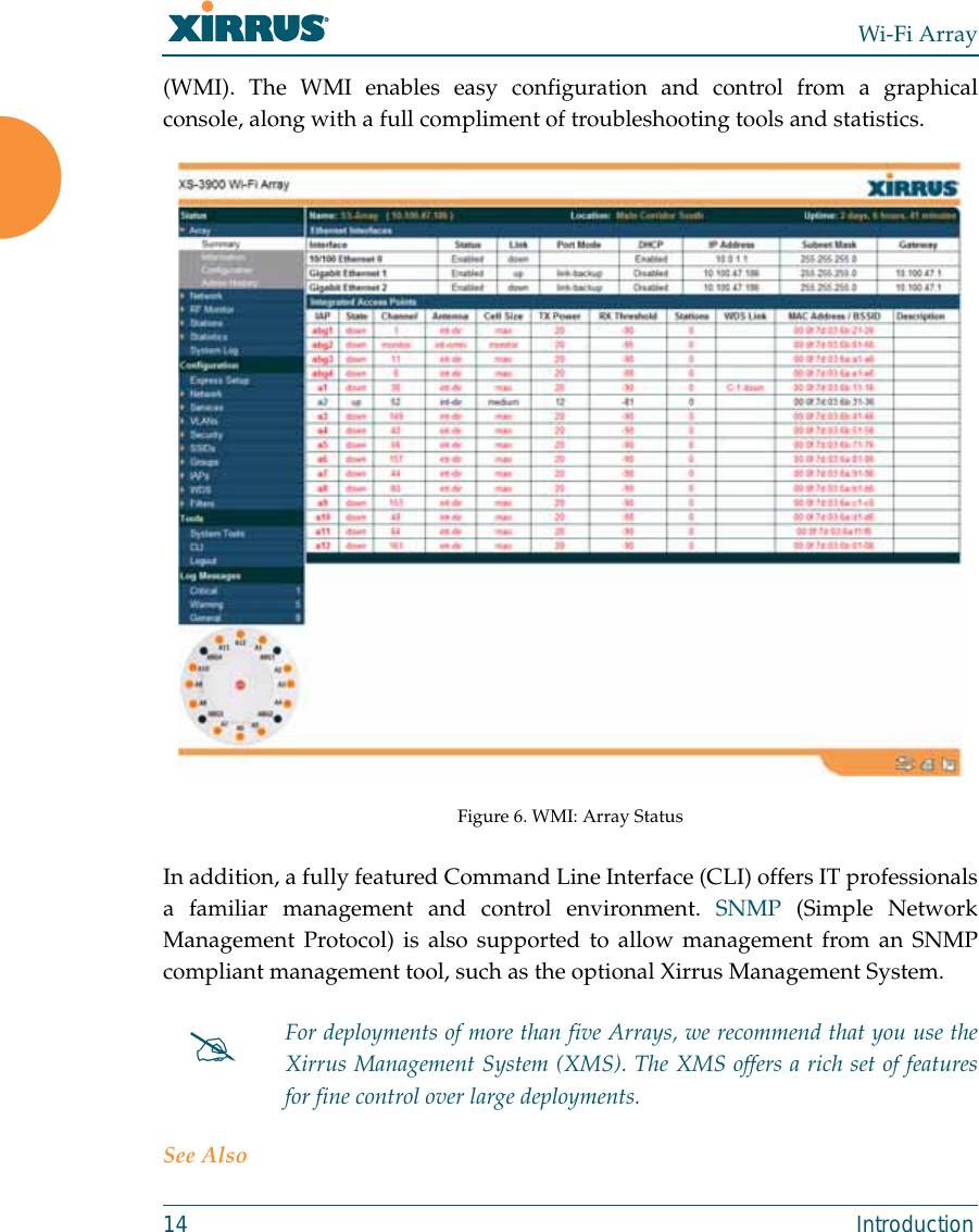
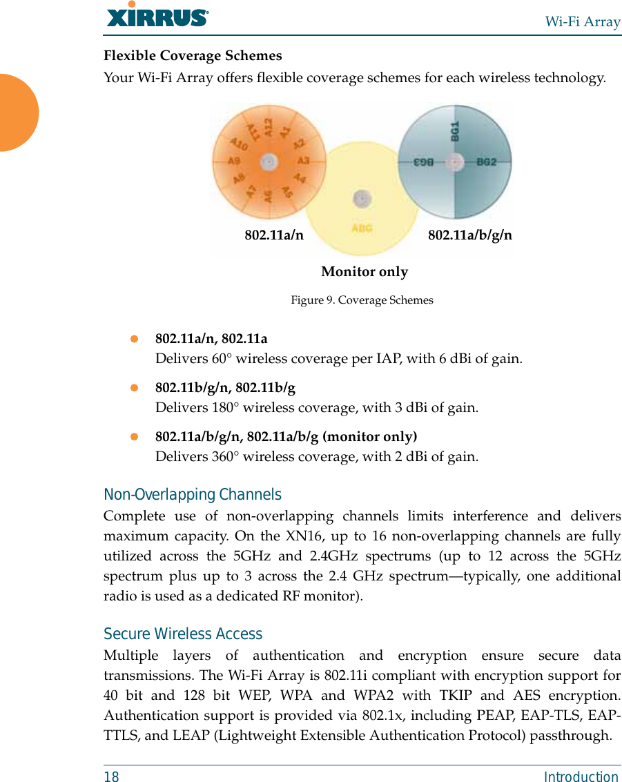
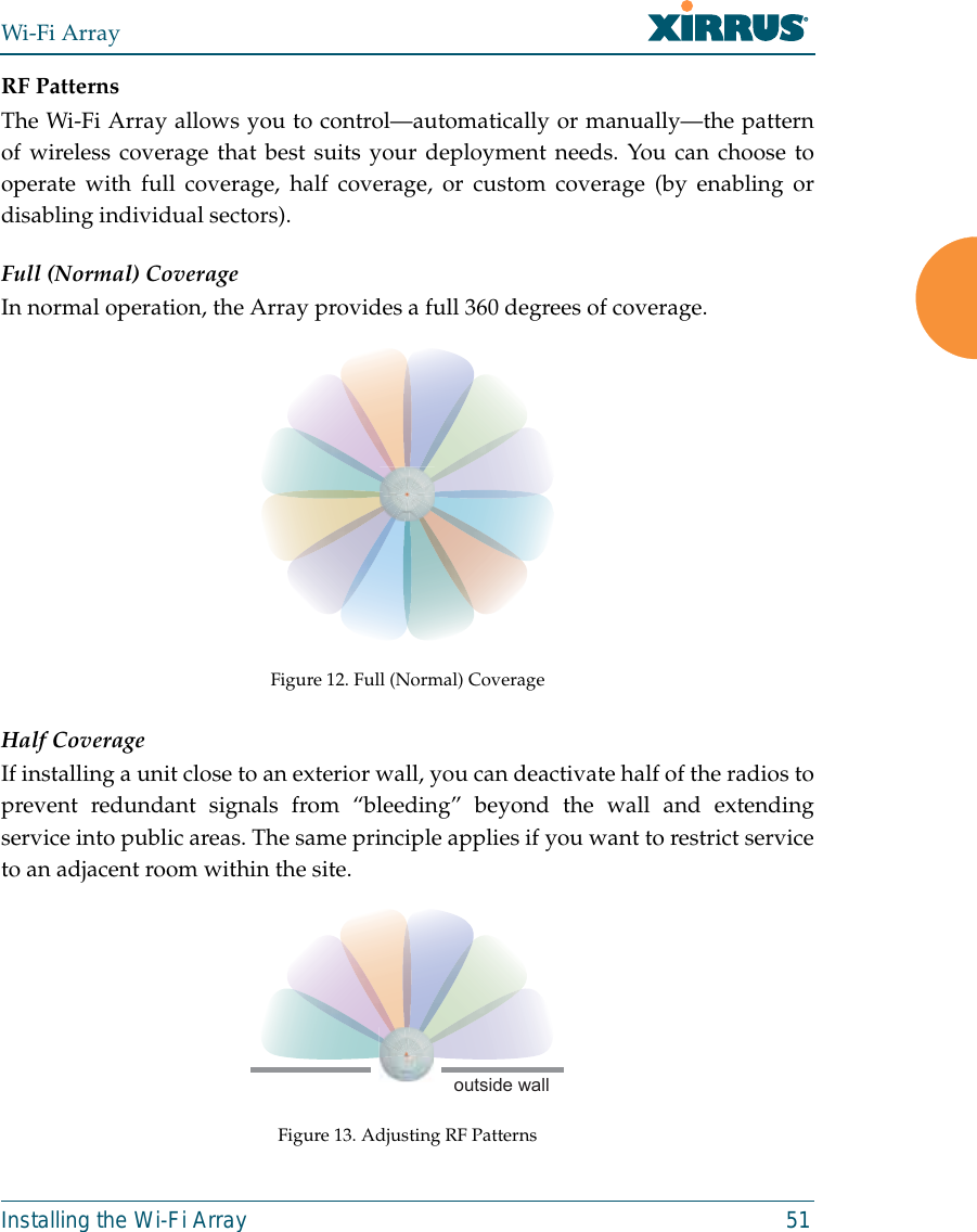
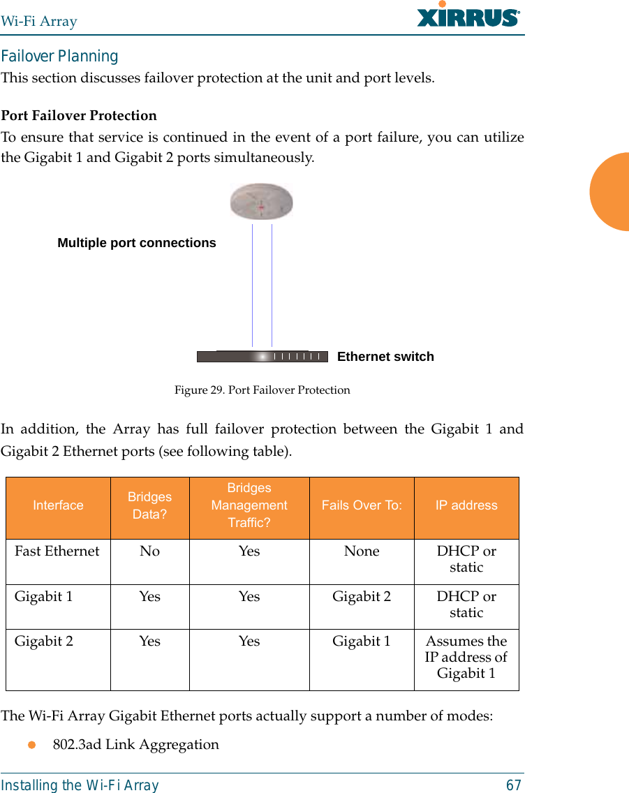
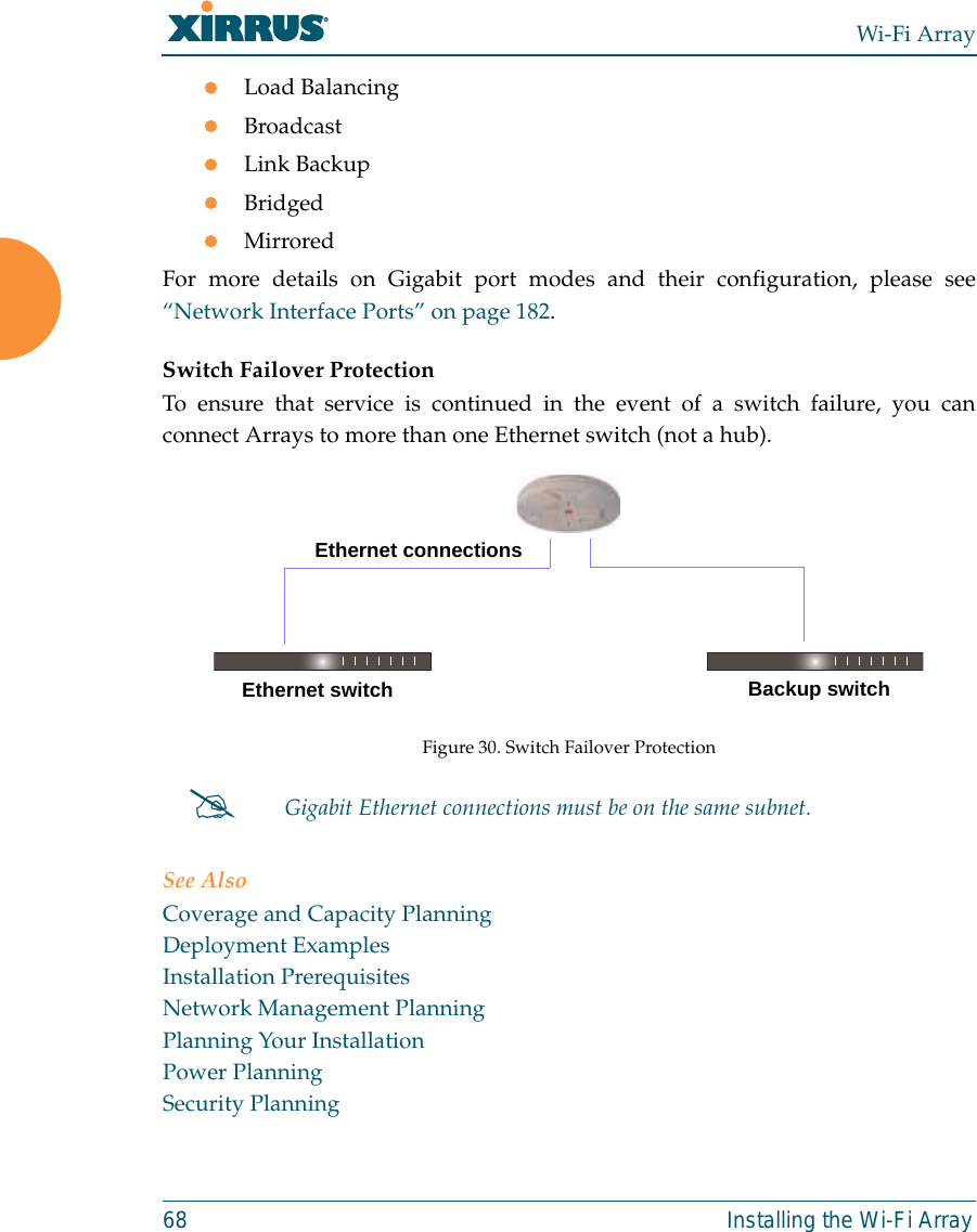
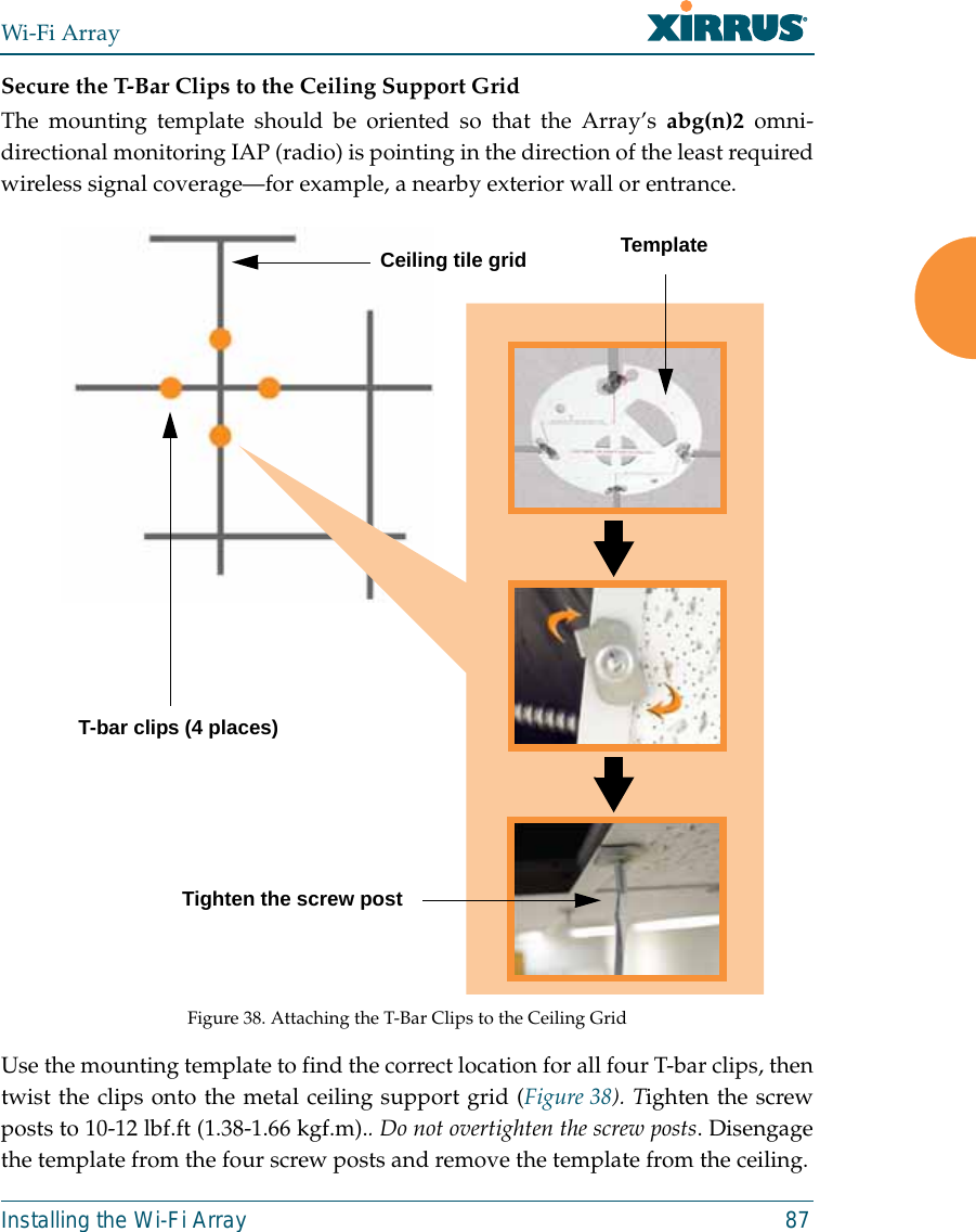
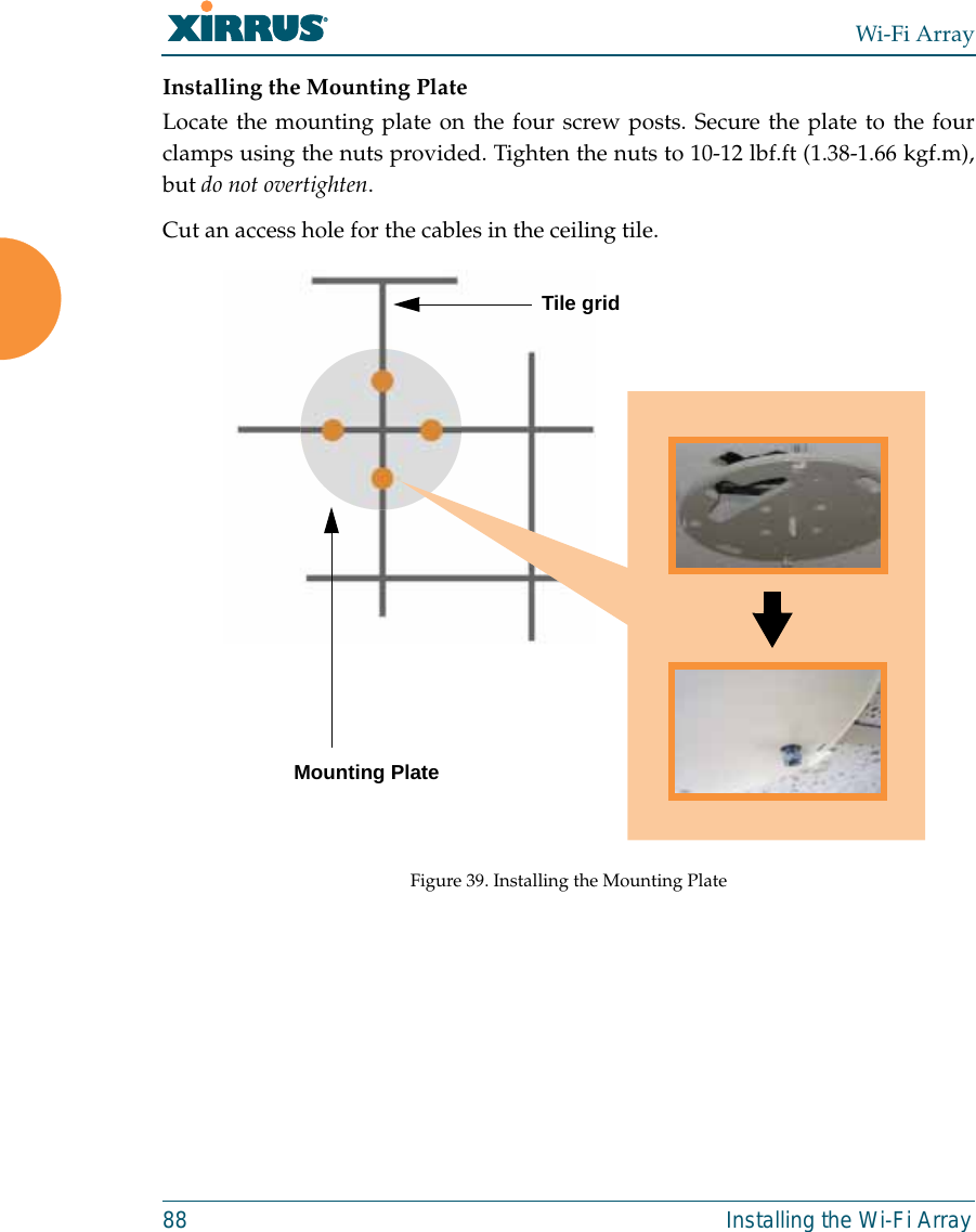
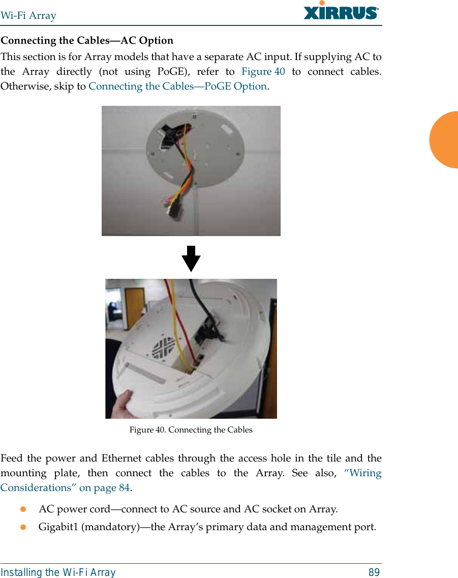
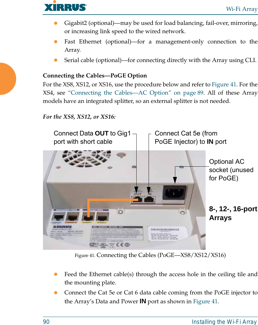
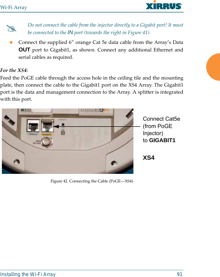
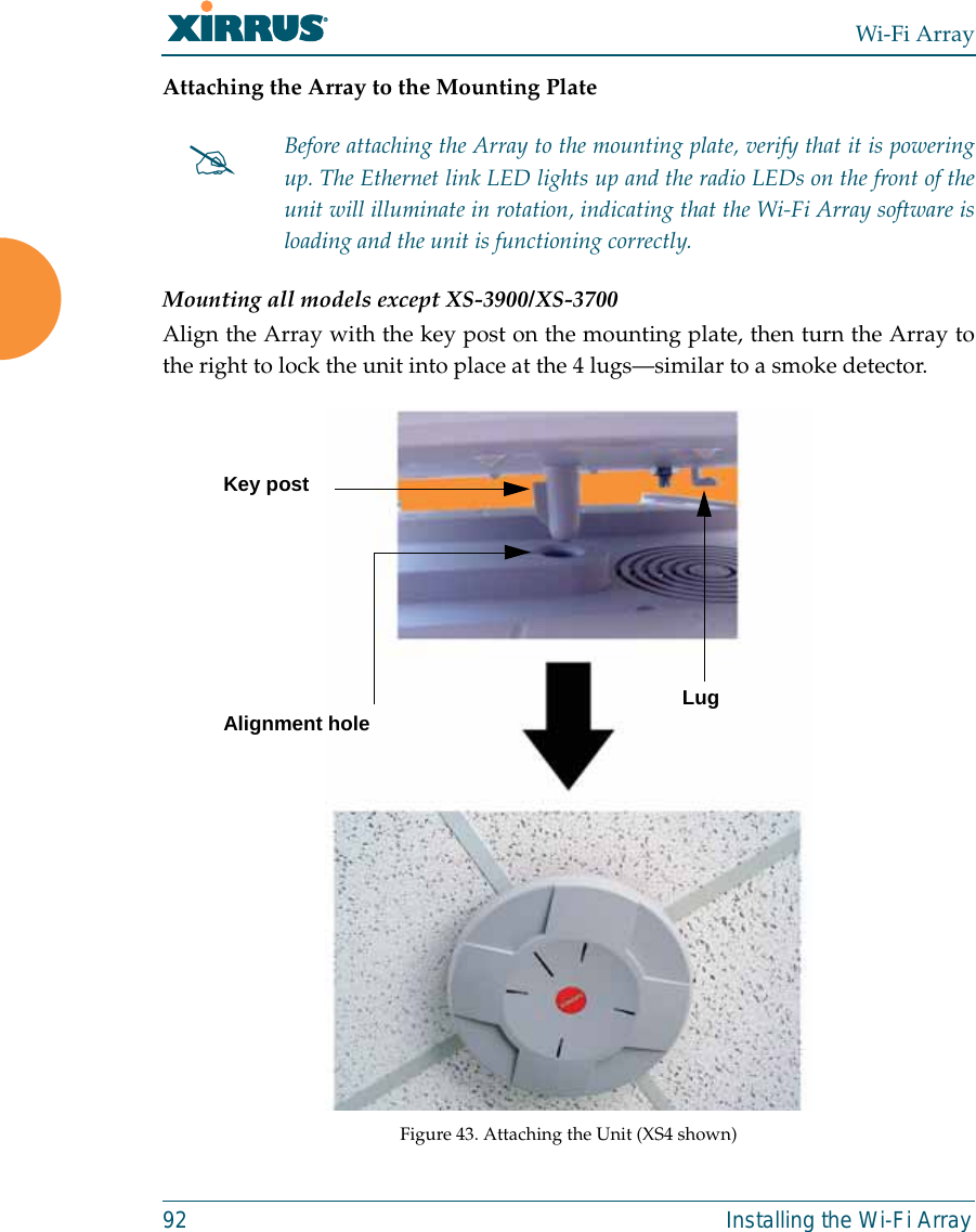
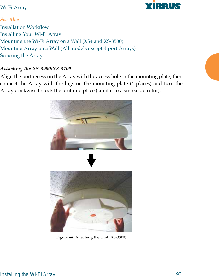
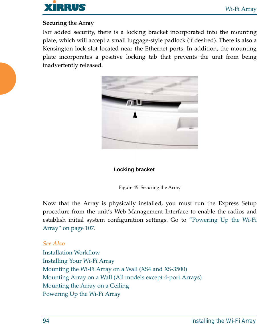
A Pages 1 to 125 from ArrayGuide Rel4 SS Dec02 2008