Cambium Networks XN12 WIRELESS LAN ARRAY User Manual
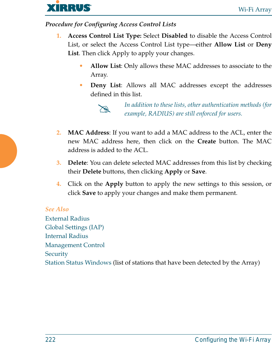
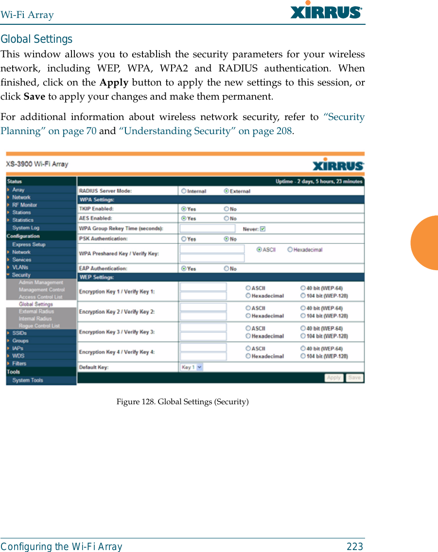
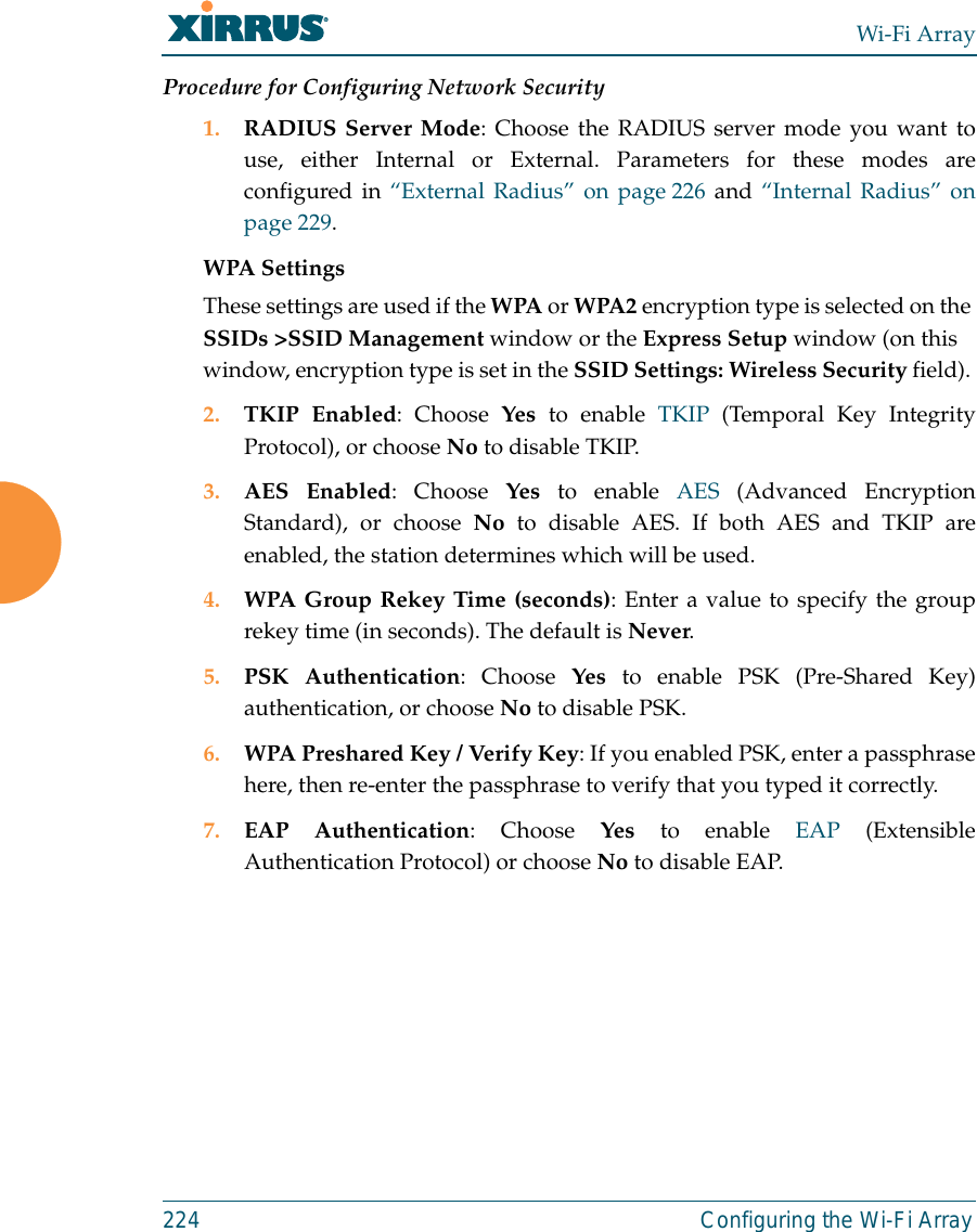
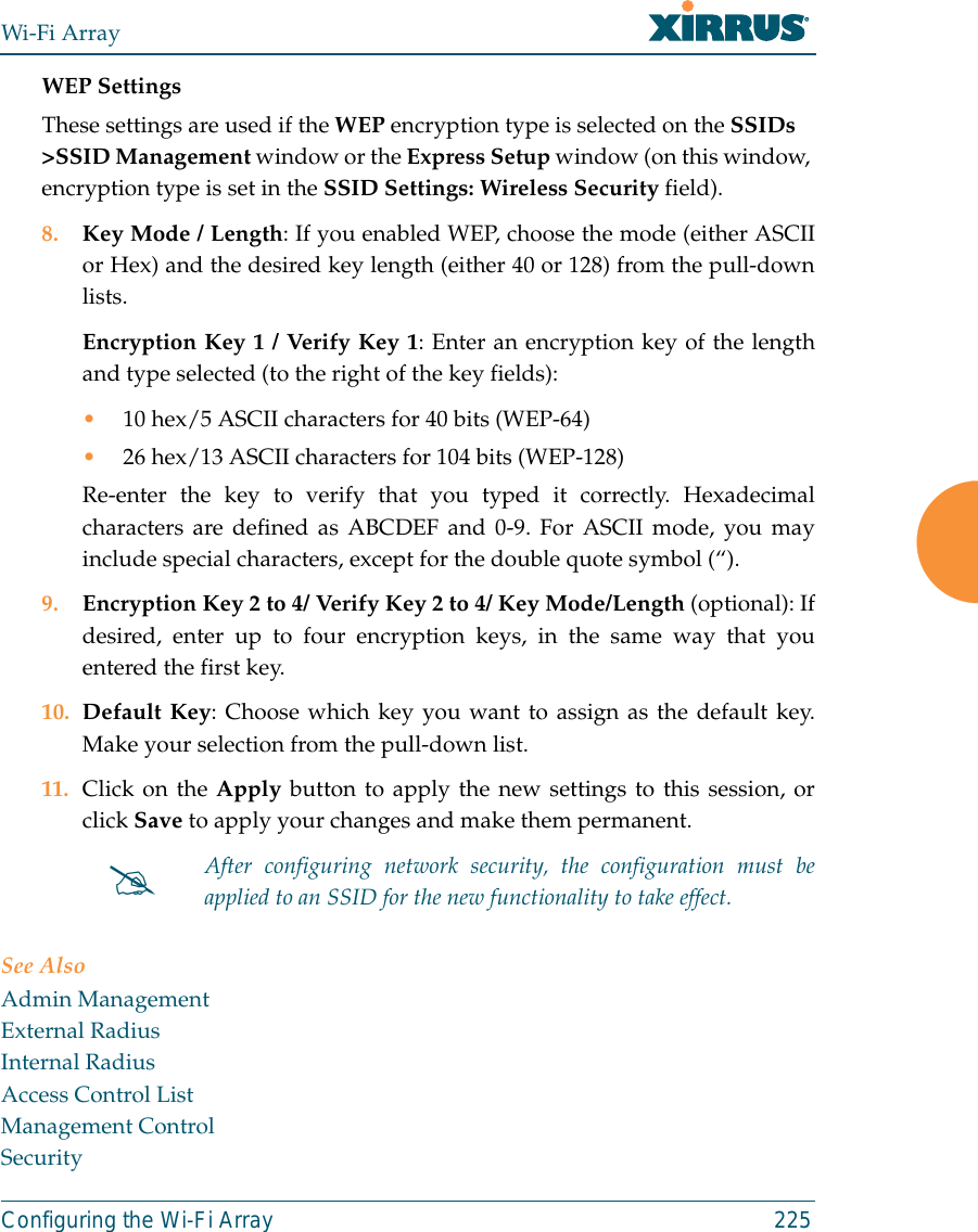
Xirrus, Inc. WIRELESS LAN ARRAY
Contents
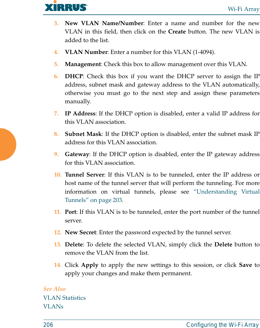
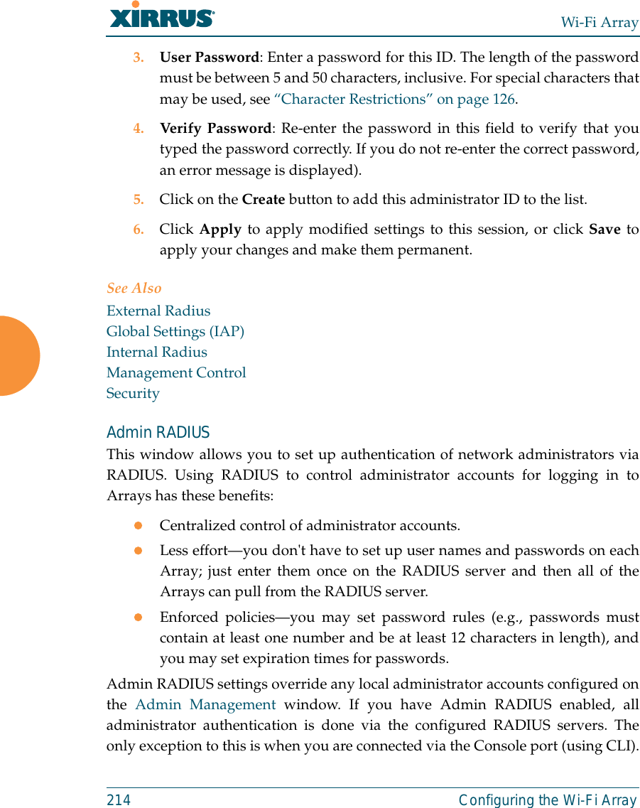
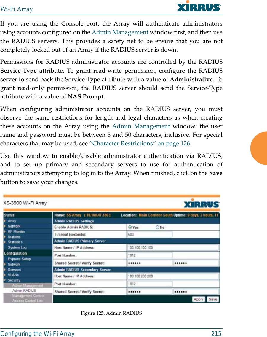
- 1. Users Manual 1of5
- 2. Users Manual 2of5
- 3. Users Manual 3of5
- 4. Users Manual 4of5
- 5. Users Manual 5of5
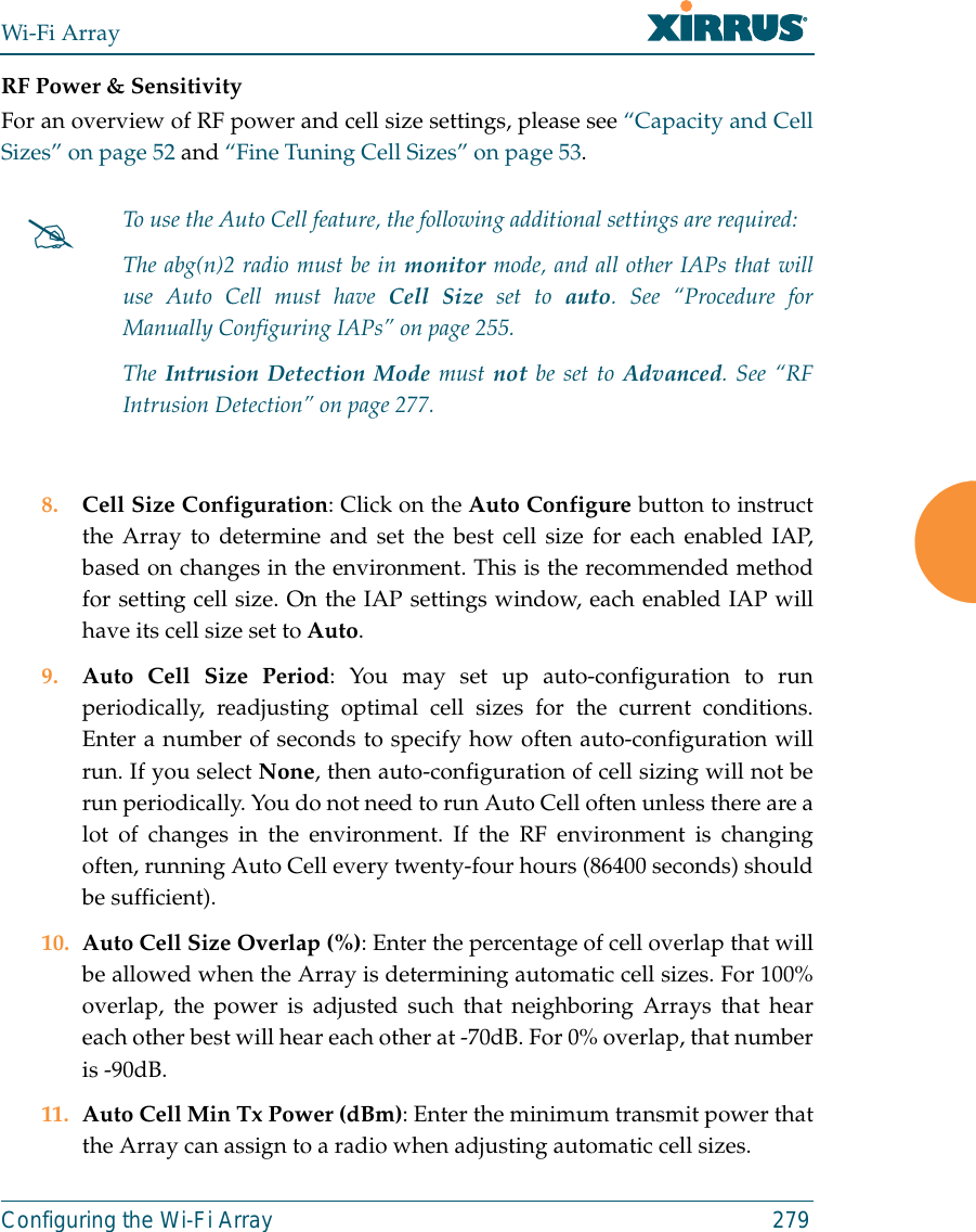
- 6. A Pages 1 to 125 from ArrayGuide Rel4 SS Dec02 2008
- 7. B Pages 126 to 225 from ArrayGuide Rel 4 SS Dec02 2008
- 8. C Pages 226 to 350 from ArrayGuide Rel4 SS Dec02 2008
- 9. D Pages 351 to 496 from ArrayGuide Rel4 SS Dec02 2008 Small 5
- 10. XN Guide small 1 of 5 revised
C Pages 226 to 350 from ArrayGuide Rel4 SS Dec02 2008
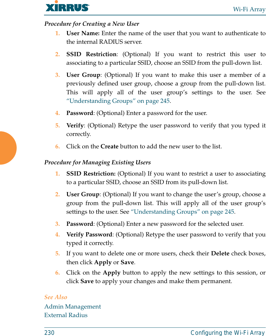
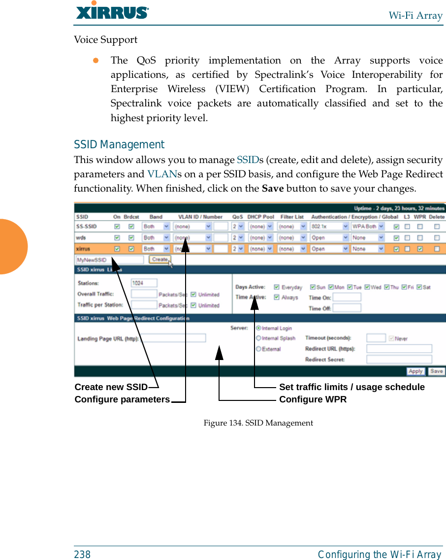
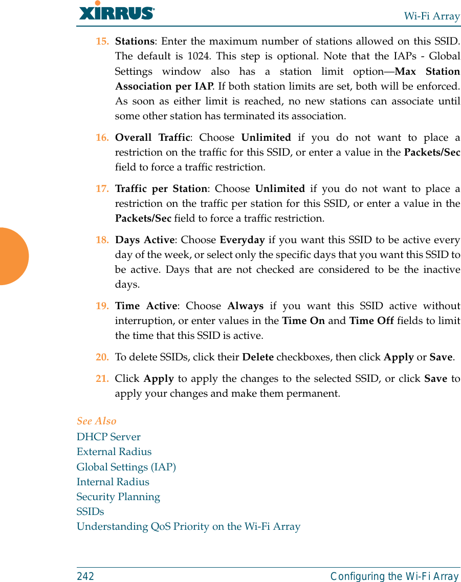
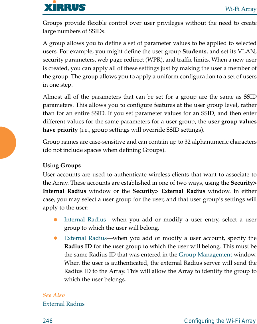
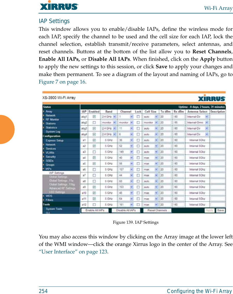
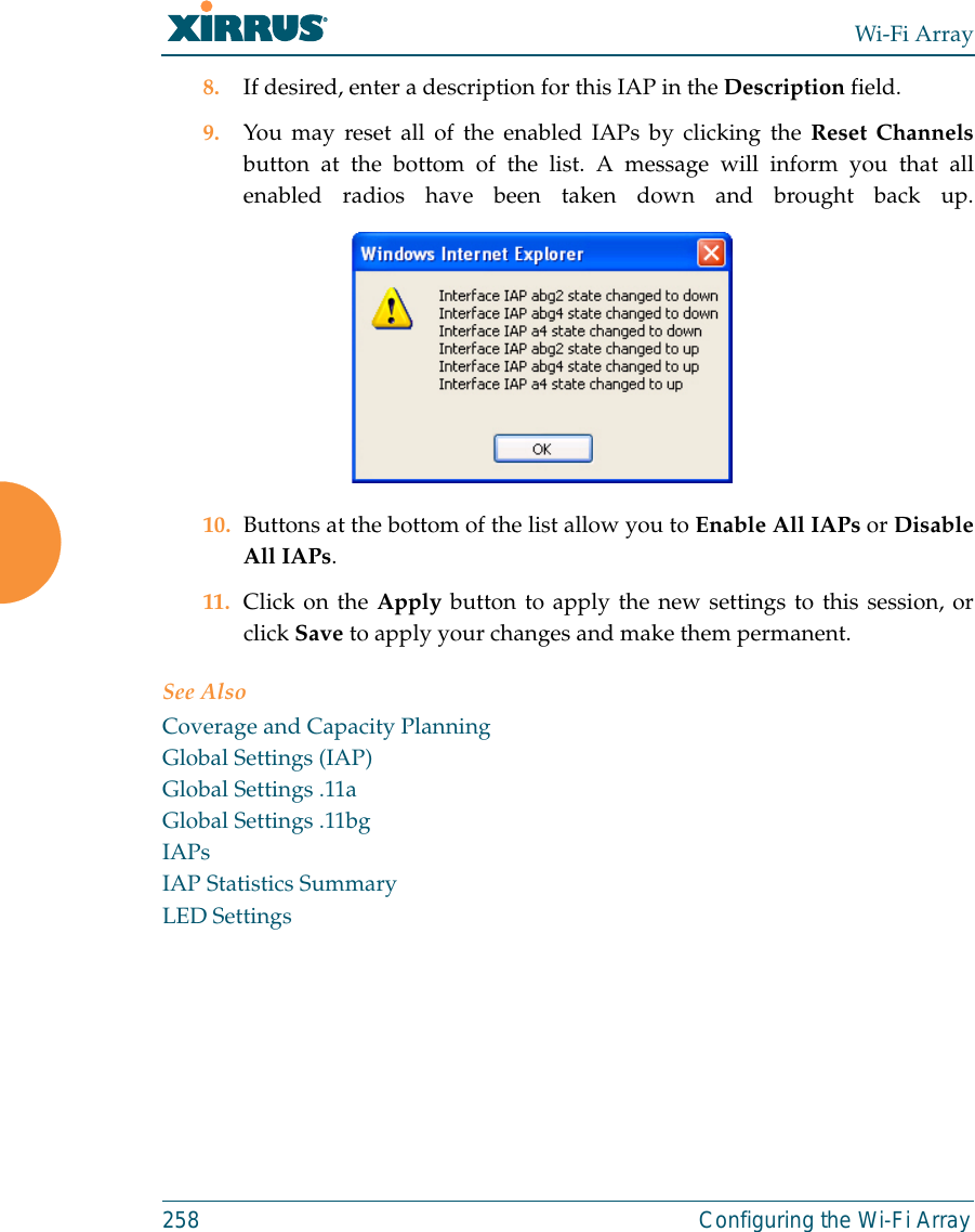

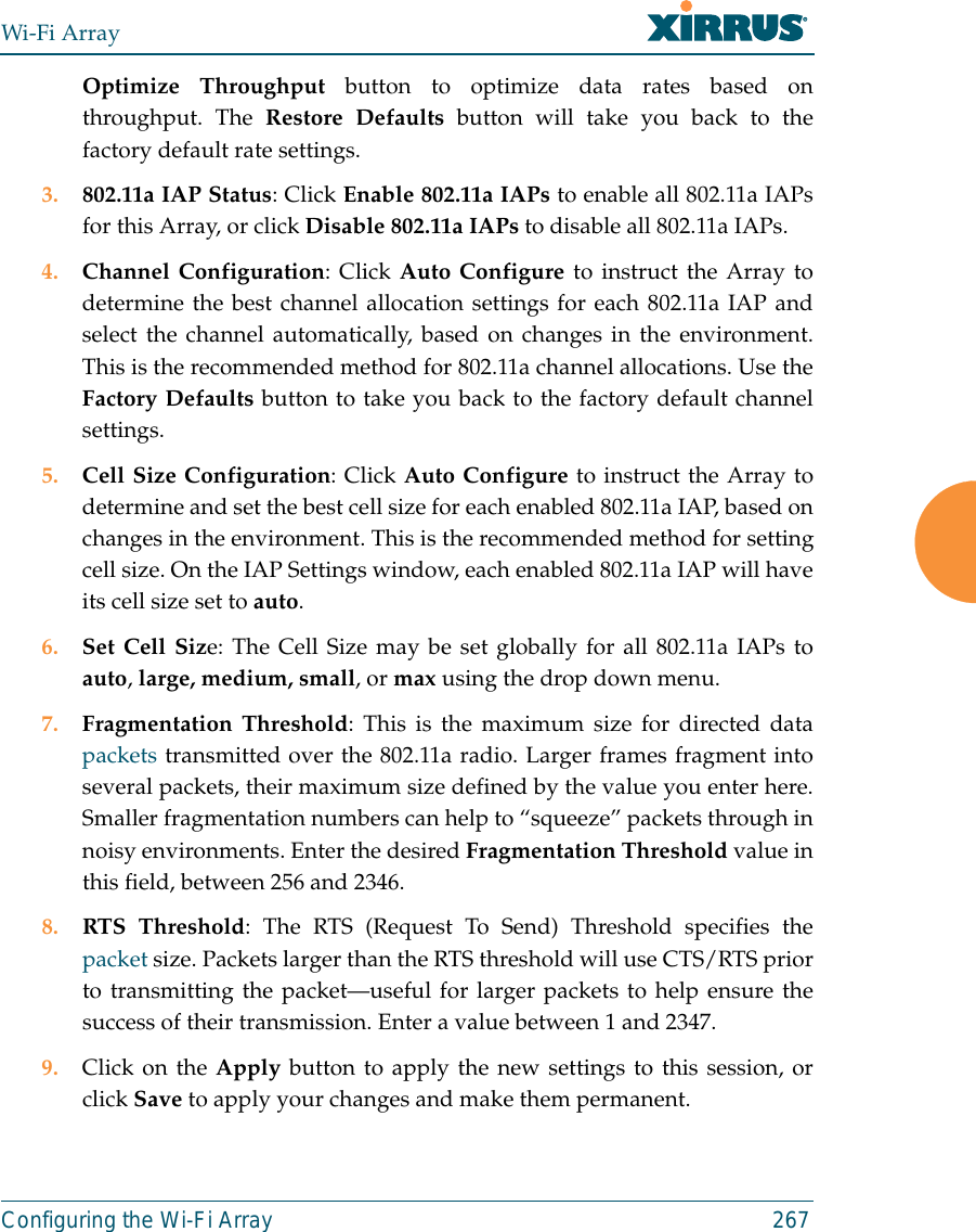
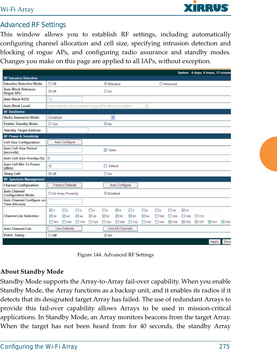
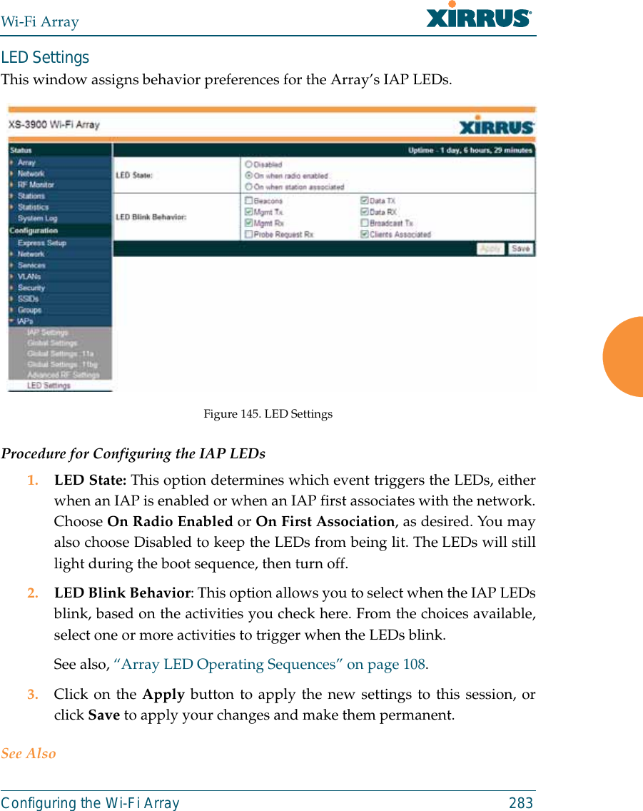
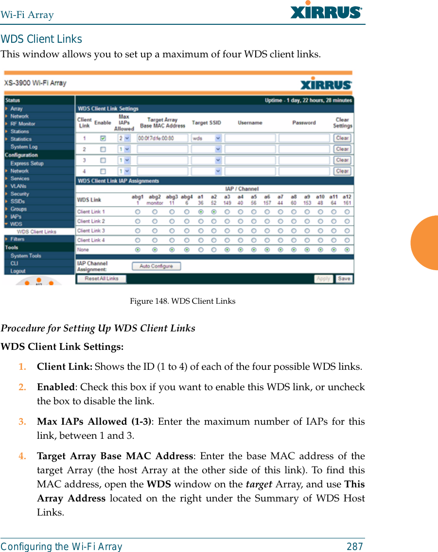
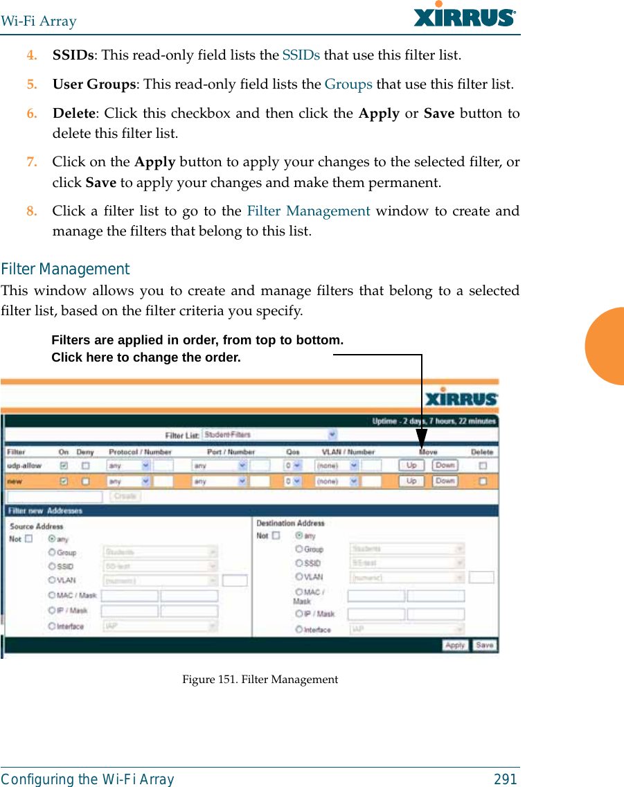
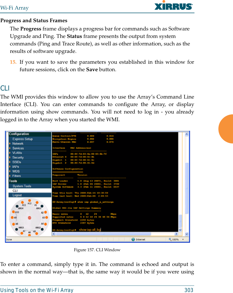
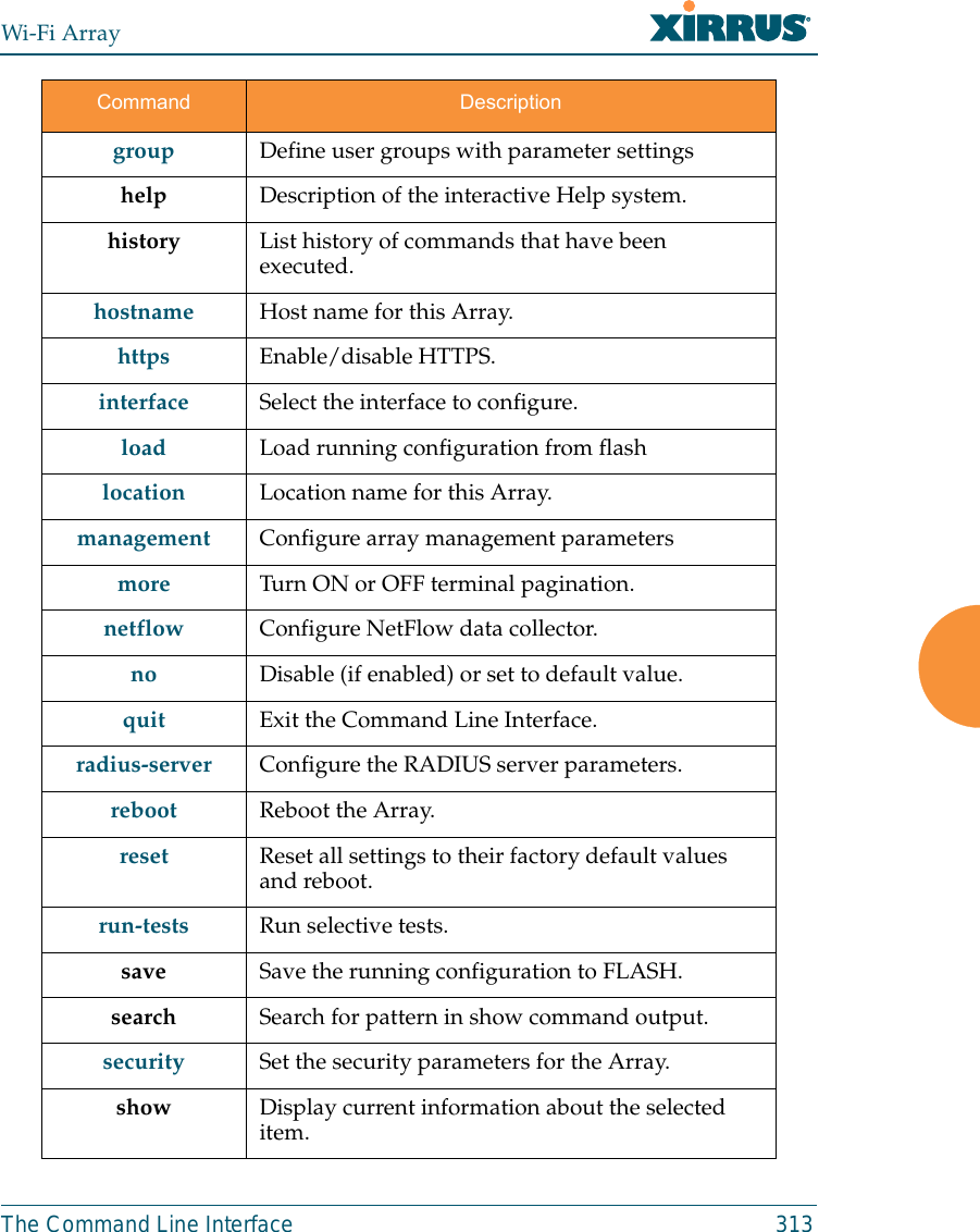
![Wi-Fi ArrayThe Command Line Interface 311Top Level CommandsThis section offers an at-a-glance view of all top level commands—organizedalphabetically. Top level commands are defined here as commands that aredirectly accessible from the root command prompt (Xirrus_Wi-Fi_Array#). Theroot command prompt is based on the host name assigned to your Array. Wheninputting commands, be aware that all commands are case-sensitive.All other commands are considered second level configuration commands—theseare the commands you use to configure specific elements of the Array’s featuresand functionality. For a listing of these commands with examples of commandformats and structure, go to “Configuration Commands” on page 320.Root Command PromptThe following table shows the top level commands that are available from theroot command prompt [Xirrus_Wi-Fi_Array].Command Description@ Type @n to execute command n (as shown by the history command).configure Enter the configuration mode. See “Configuration Commands” on page 320. exit Exit the CLI and terminate your session—if this command is used at any level other than the root command prompt you will simply exit the current level (step back) and return to the previous level.help Show a description of the interactive help system. See also, “Getting Help” on page 309. history List history of commands that have been executed.more Turn terminal pagination ON or OFF.quit Exit the Command Line Interface (from any level).search Search for pattern in show command output.](https://usermanual.wiki/Cambium-Networks/XN12.C-Pages-226-to-350-from-ArrayGuide-Rel4-SS-Dec02-2008/User-Guide-1071267-Page-106.png)
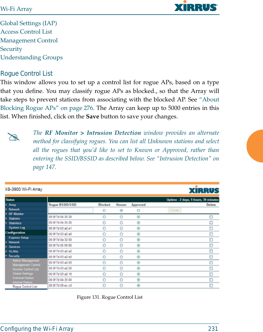
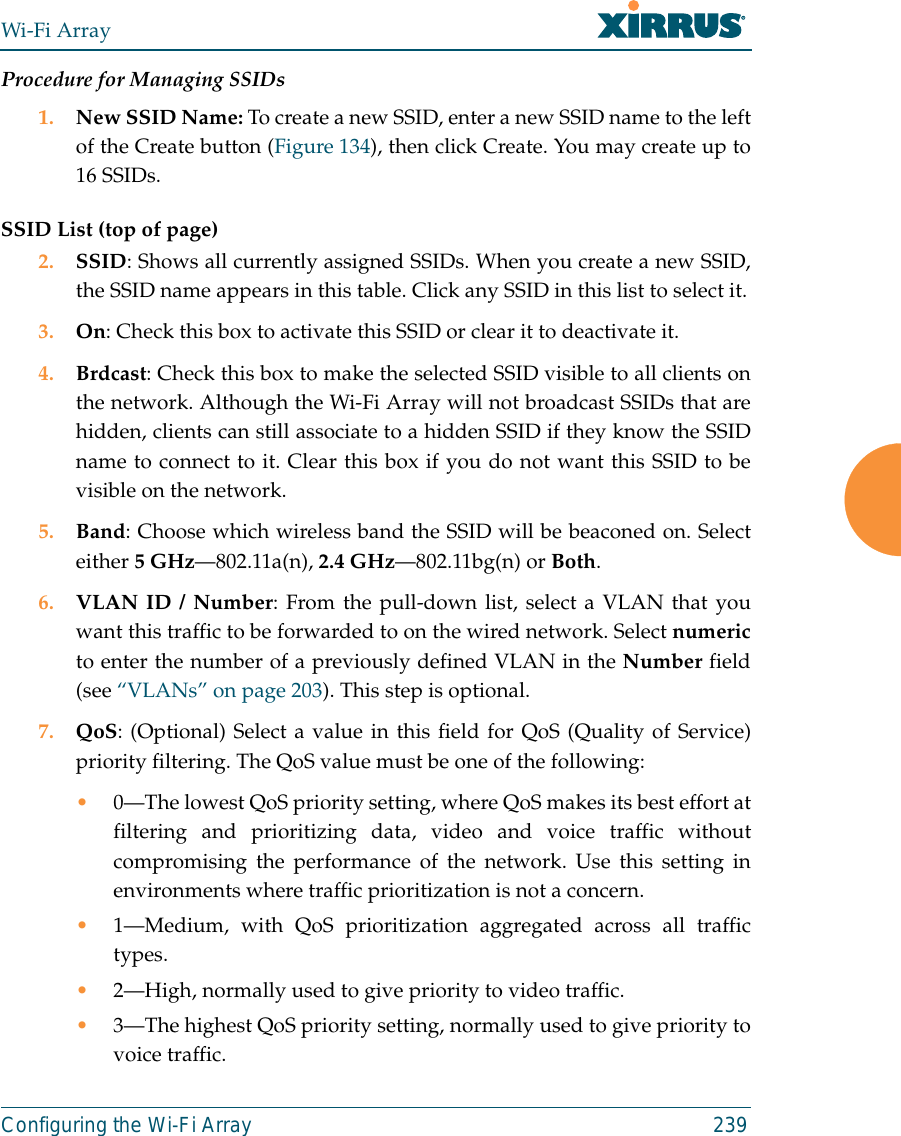
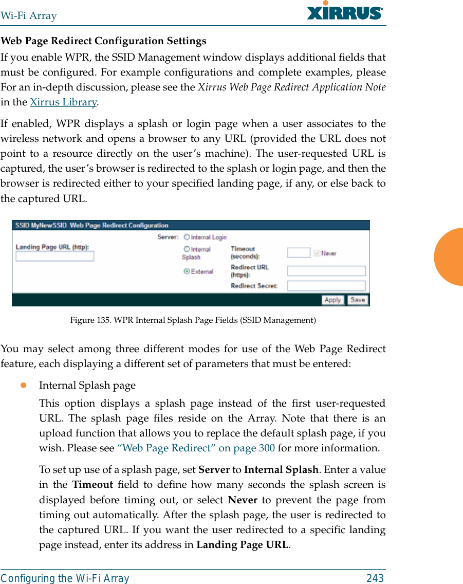
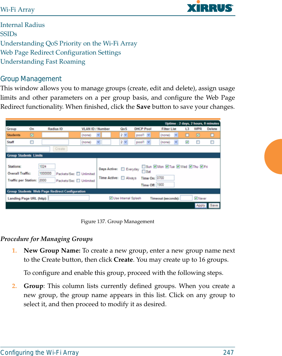
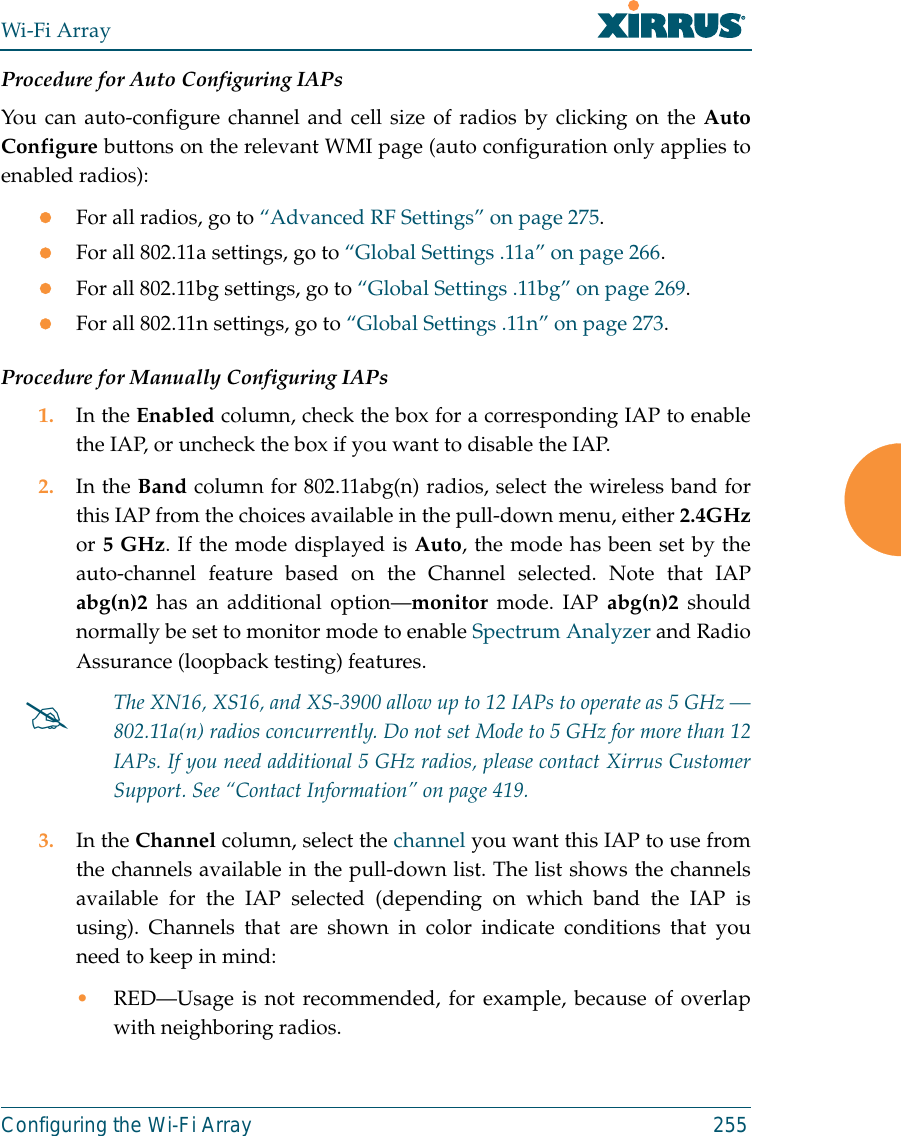
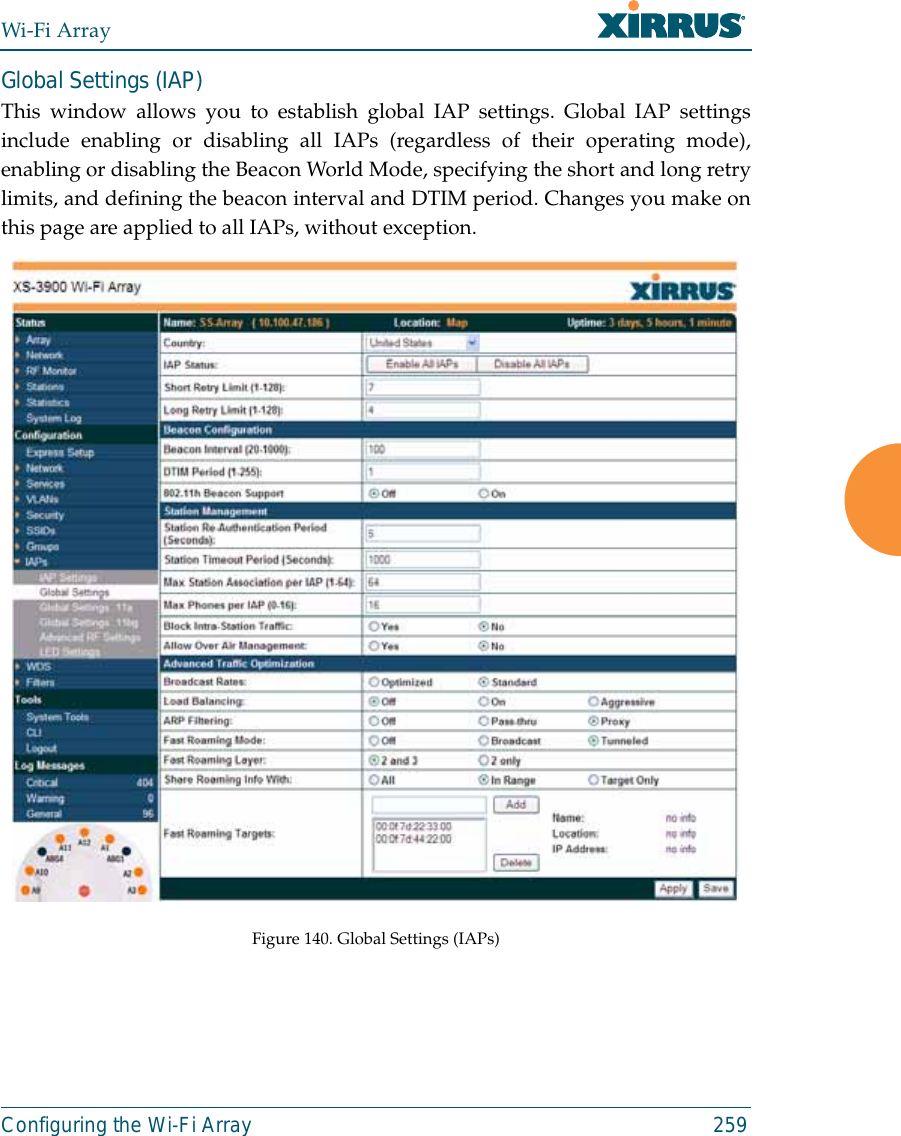
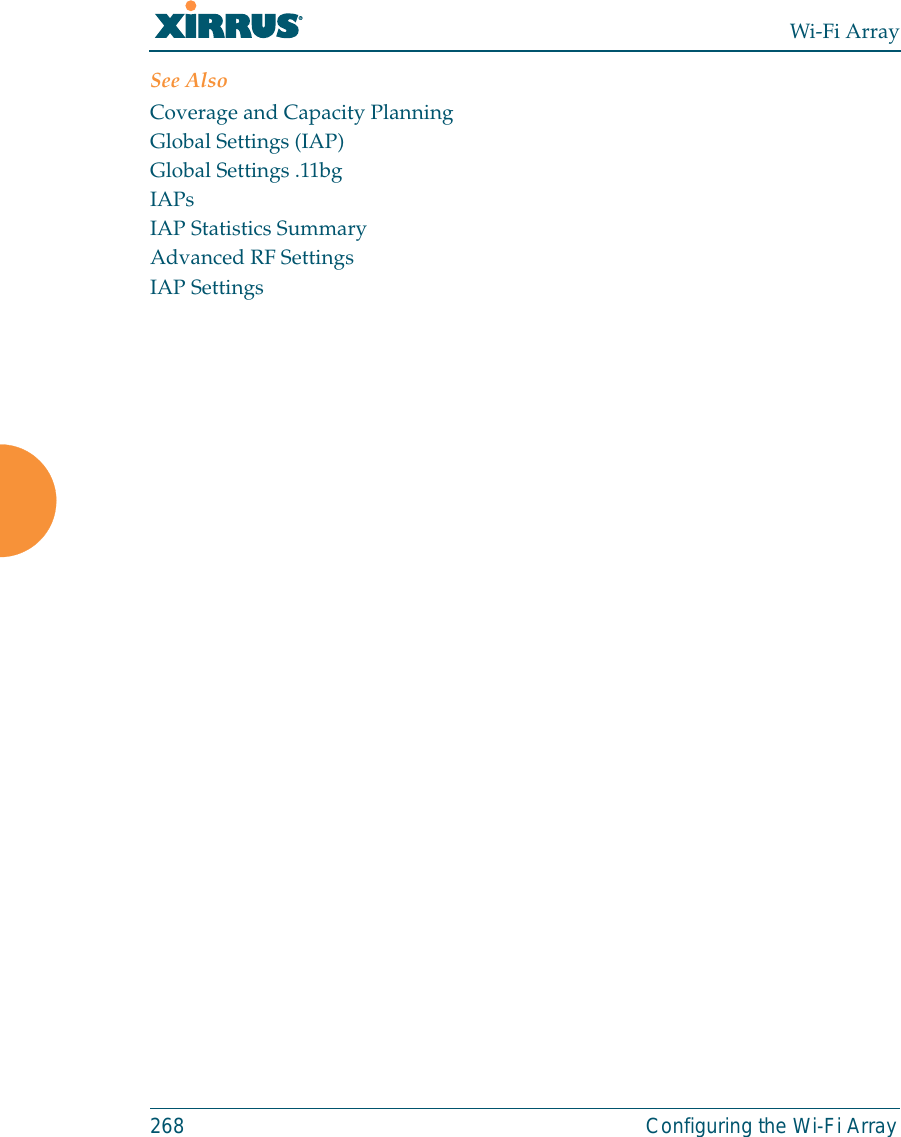
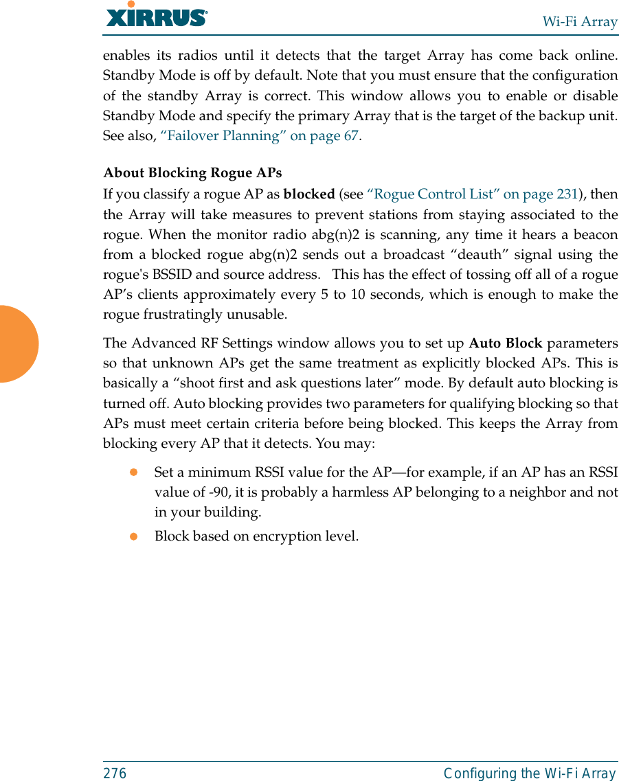
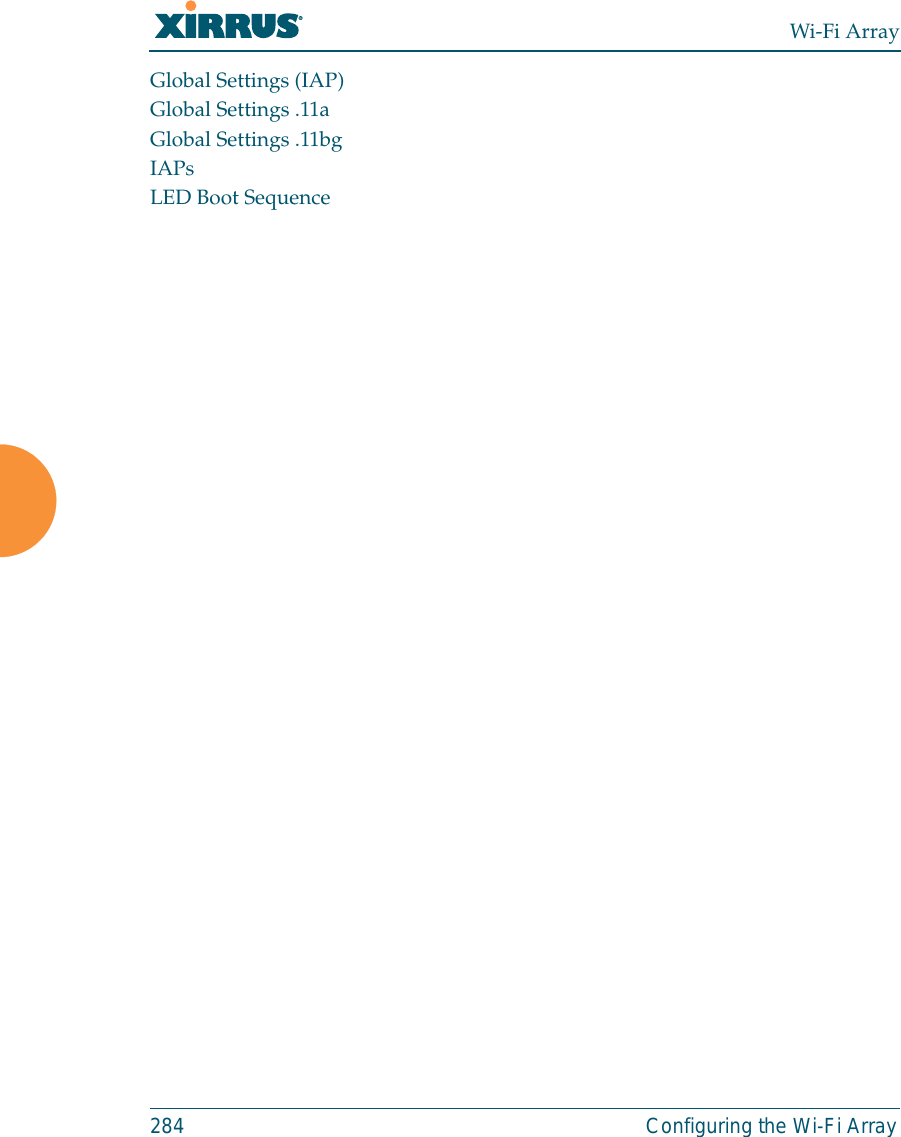
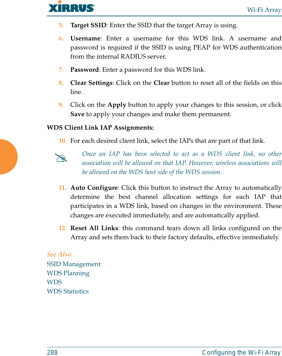
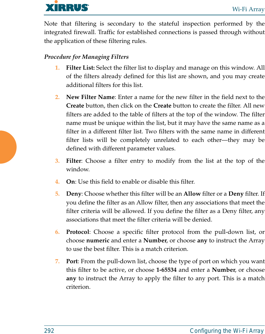
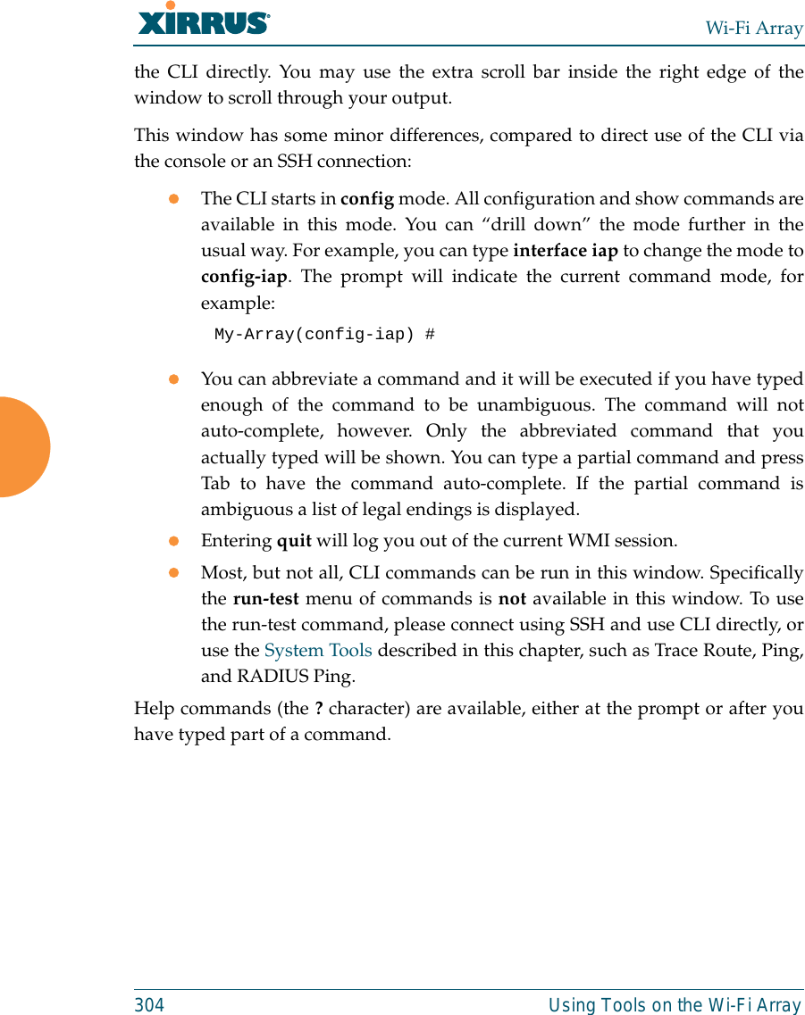
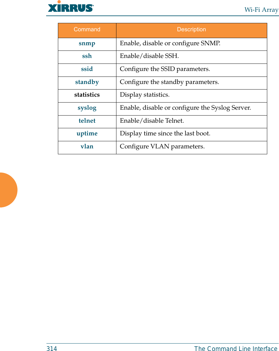
![Wi-Fi Array312 The Command Line Interfaceconfigure CommandsThe following table shows the second level commands that are available with thetop level configure command [Xirrus_Wi-Fi_Array(config)#].show Display information about the selected item. See “show Commands” on page 315. statistics Display statistical data about the Array. See “statistics Commands” on page 318. uptime Display the elapsed time since the last boot.Command Description@ Type @n to execute command n (as shown by the history command).acl Configure the Access Control List.admin Define administrator access parameters. cdp Configure Cisco Discovery Protocol settings. clear Remove/clear the requested elements.contact-info Contact information for assistance on this Array.date-time Configure date and time settings.dhcp-server Configure the DHCP Server.dns Configure the DNS settings.end Exit the configuration mode.exit Go UP one mode level.file Manage the file system.filter Define protocol filter parameters.fips Enable/disable FIPS 140-2, Level 2 Security.Command Description](https://usermanual.wiki/Cambium-Networks/XN12.C-Pages-226-to-350-from-ArrayGuide-Rel4-SS-Dec02-2008/User-Guide-1071267-Page-107.png)
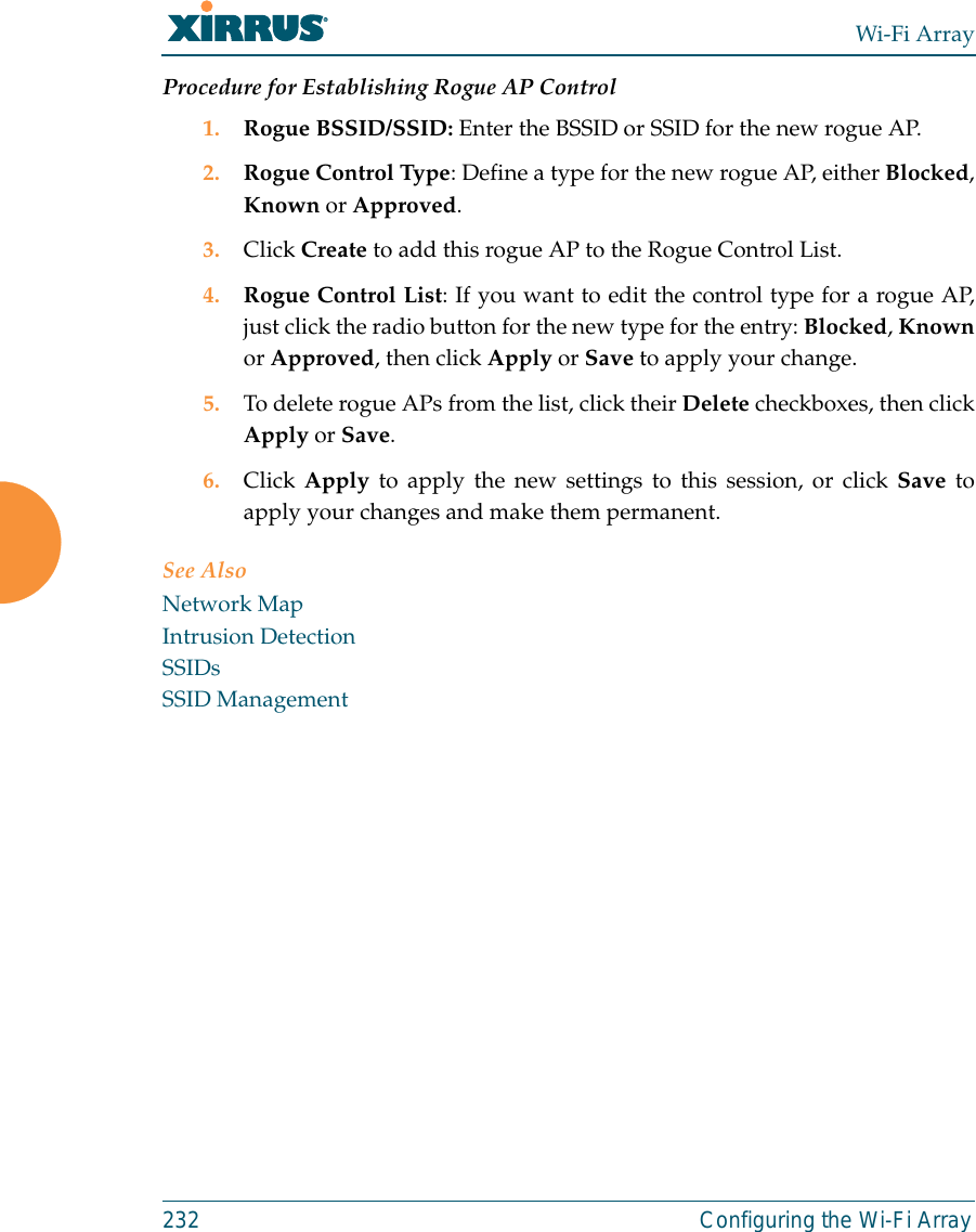
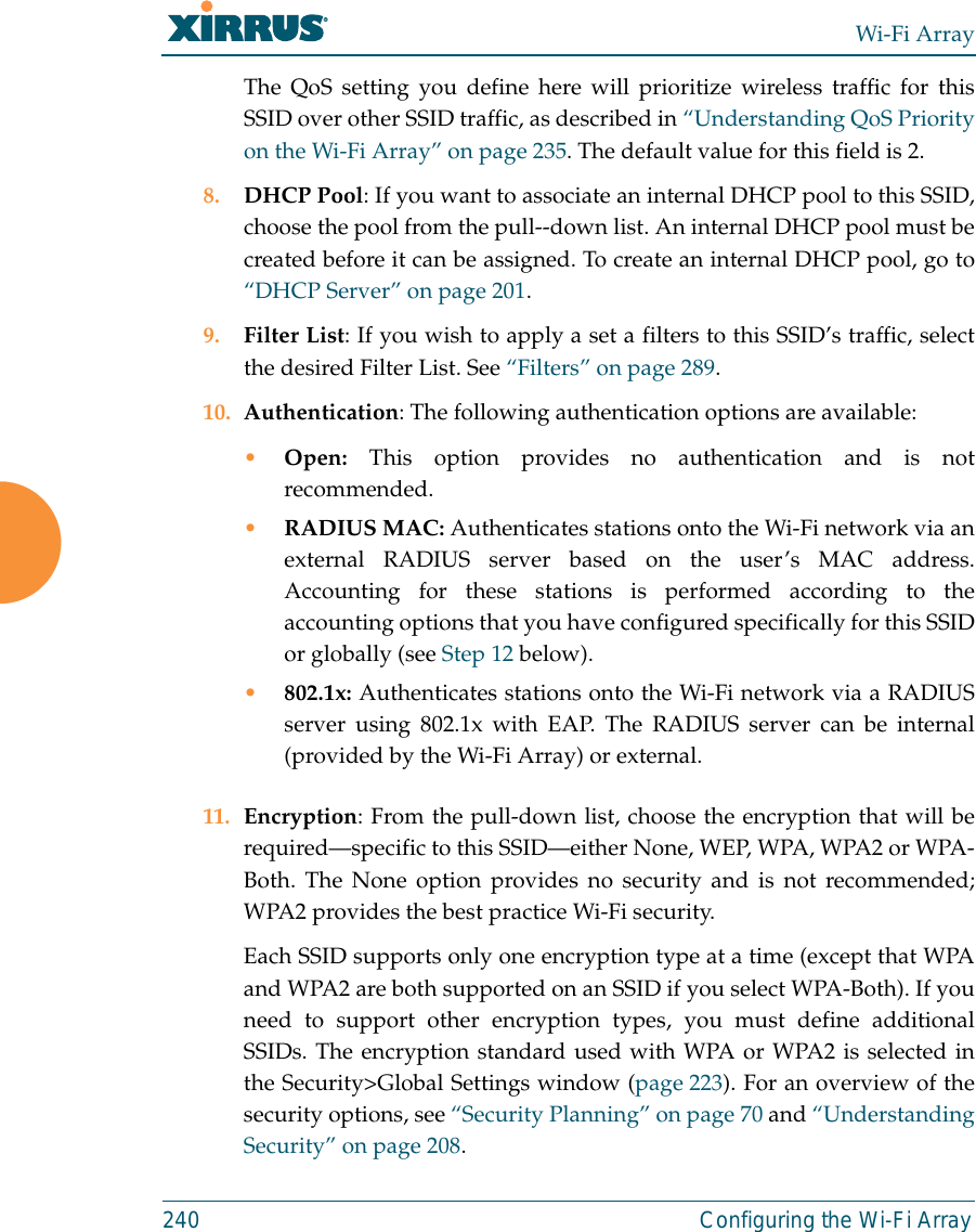
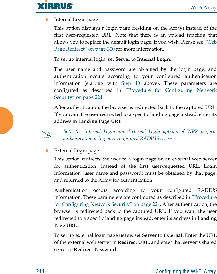
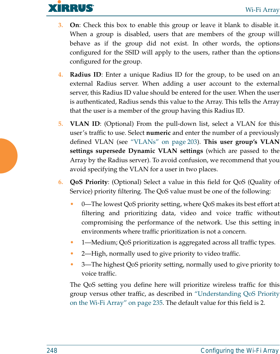
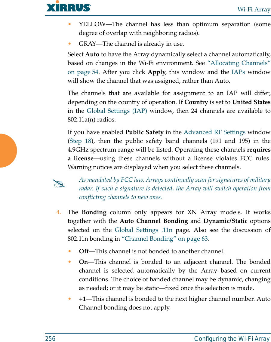
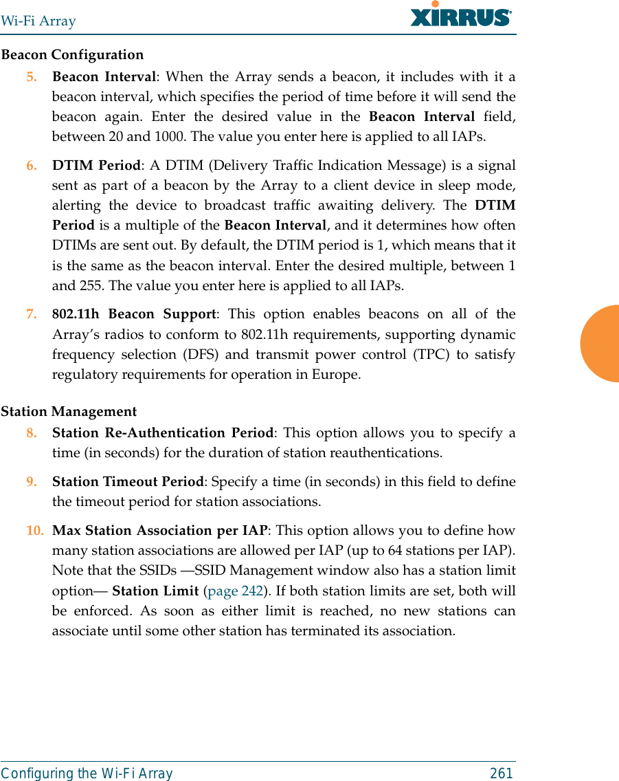
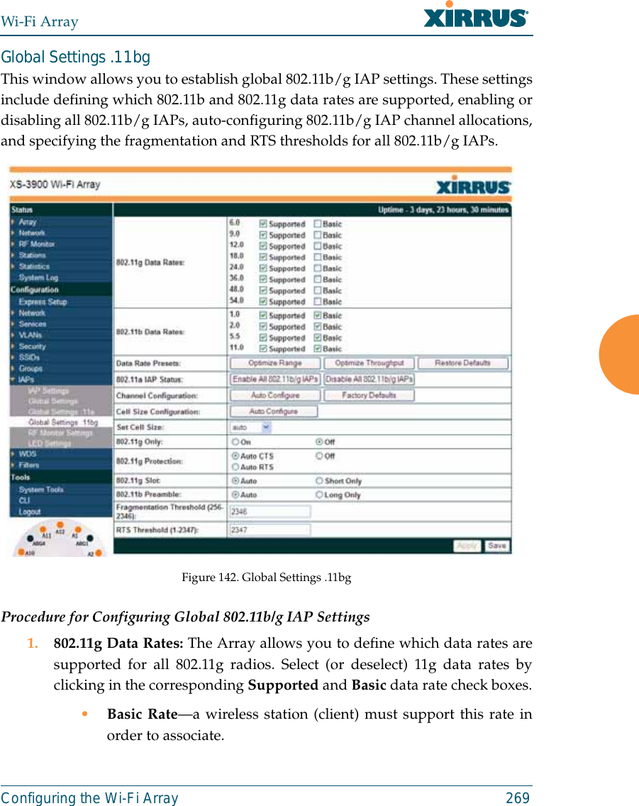
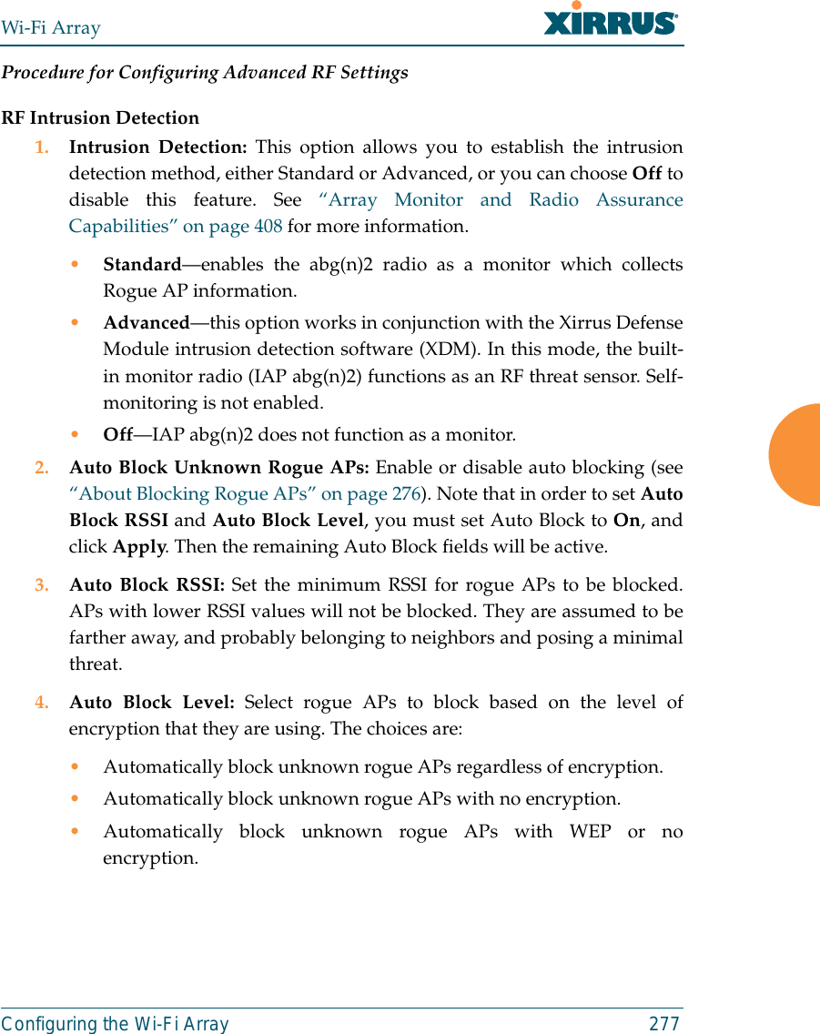
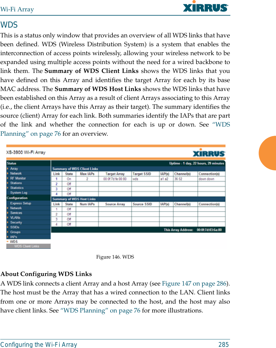
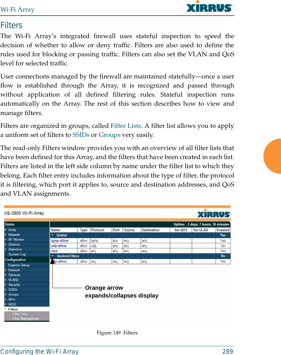
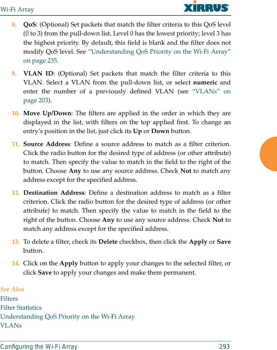
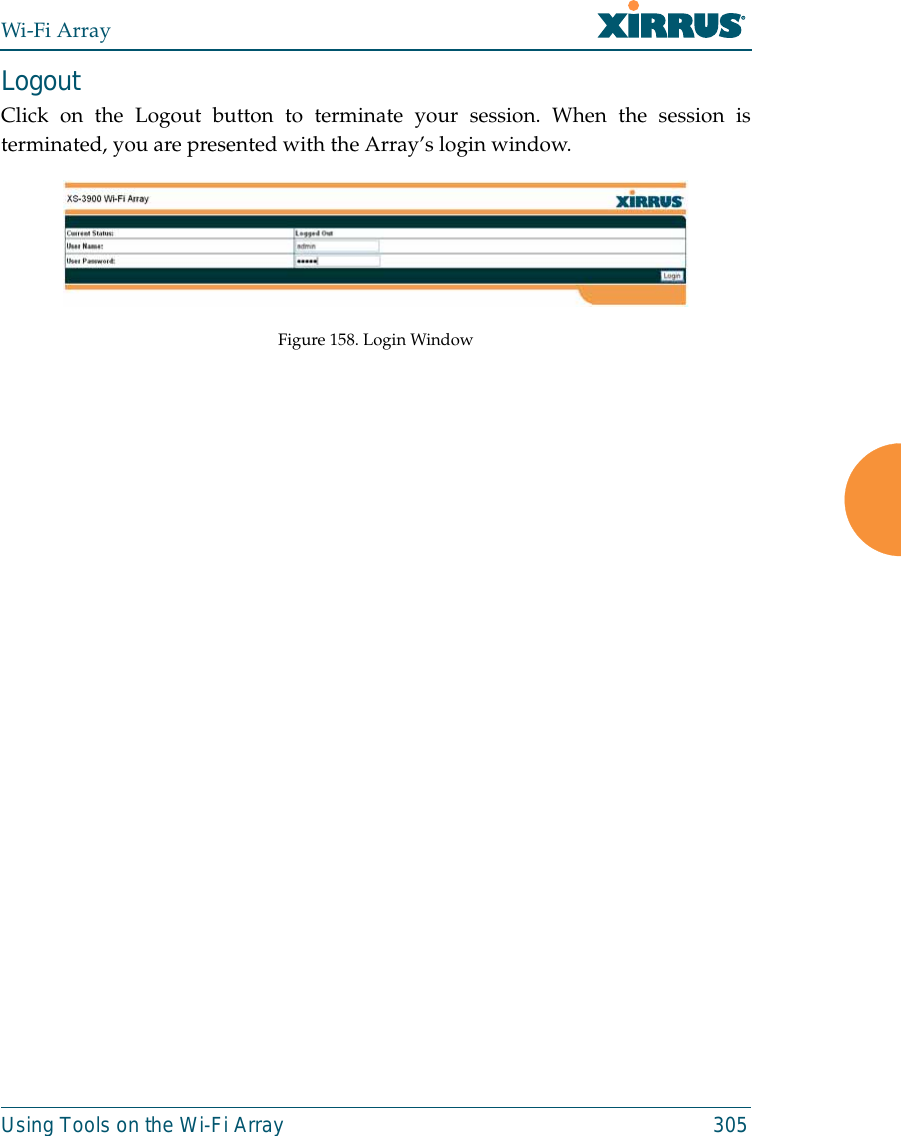
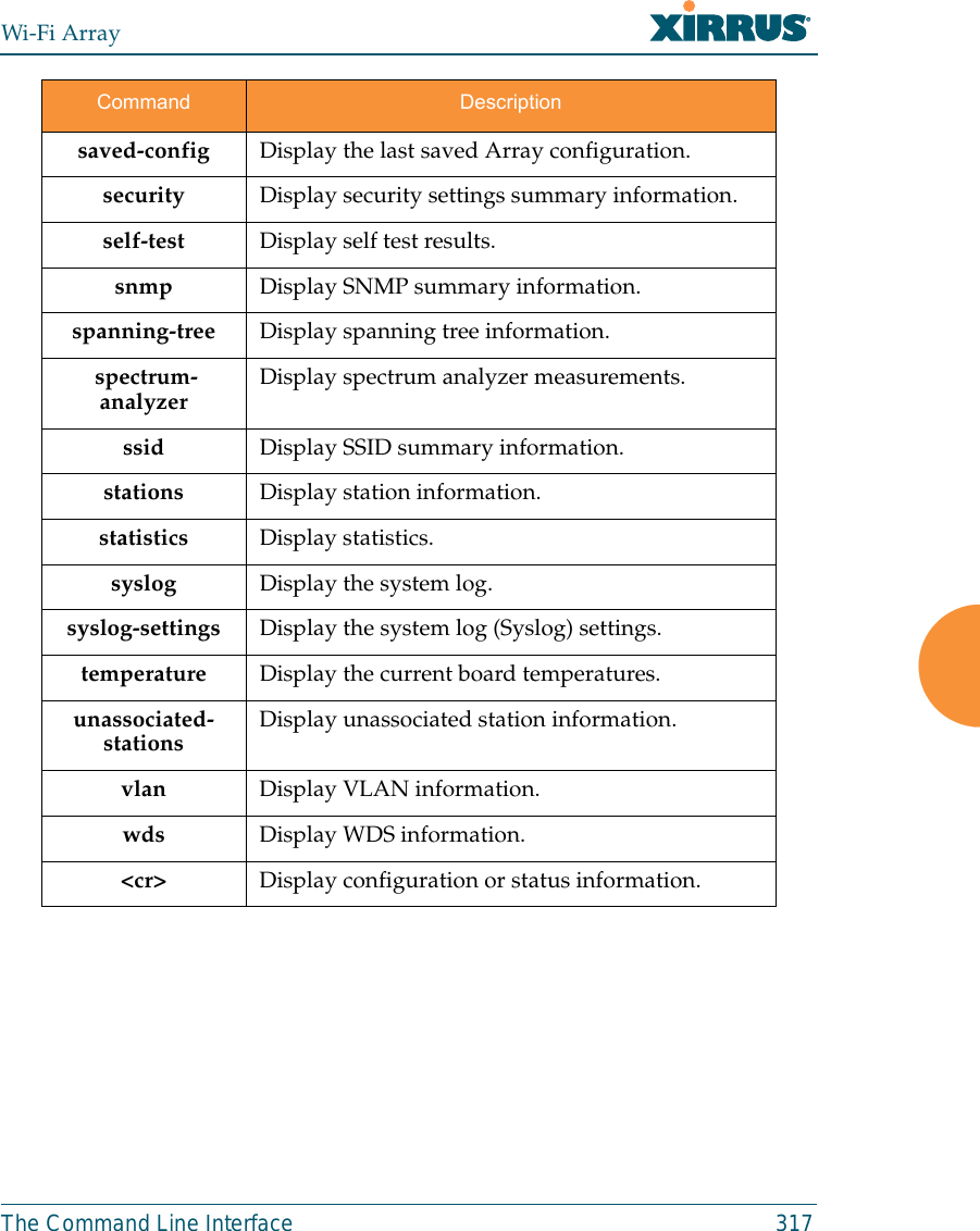
![Wi-Fi ArrayThe Command Line Interface 315show CommandsThe following table shows the second level commands that are available with thetop level show command [Xirrus_Wi-Fi_Array# show].Command Descriptionacl Display the Access Control List.admin Display the administrator list or login information.array-info Display system information.associated-stations Display stations that have associated to the Array.boot-env Display Boot loader environment variables. capabilities Display detailed station capabilities. cdp Display Cisco Discovery Protocol settings.channel-list Display list of Array’s 802.11a(n) and bg(n) channels. clear-text Display and enter passwords and secrets in the clear. conntrack Display the Connection Tracking table. console Display terminal settings.contact-info Display contact information.country-list Display countries that the Array can be set to support. date-time Display date and time settings summary.dhcp-leases Display IP addresses (leases) assigned to stations by the DHCP server. dhcp-pool Display internal DHCP server settings summary information.](https://usermanual.wiki/Cambium-Networks/XN12.C-Pages-226-to-350-from-ArrayGuide-Rel4-SS-Dec02-2008/User-Guide-1071267-Page-110.png)

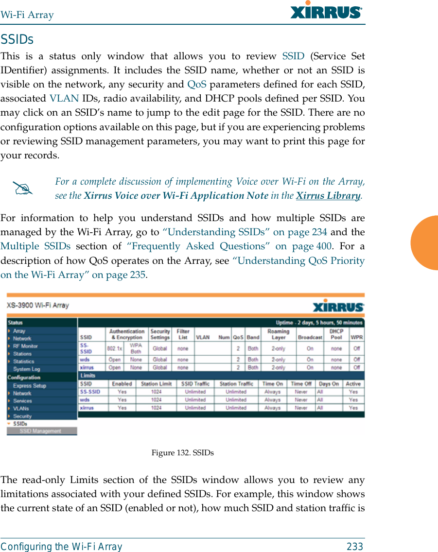
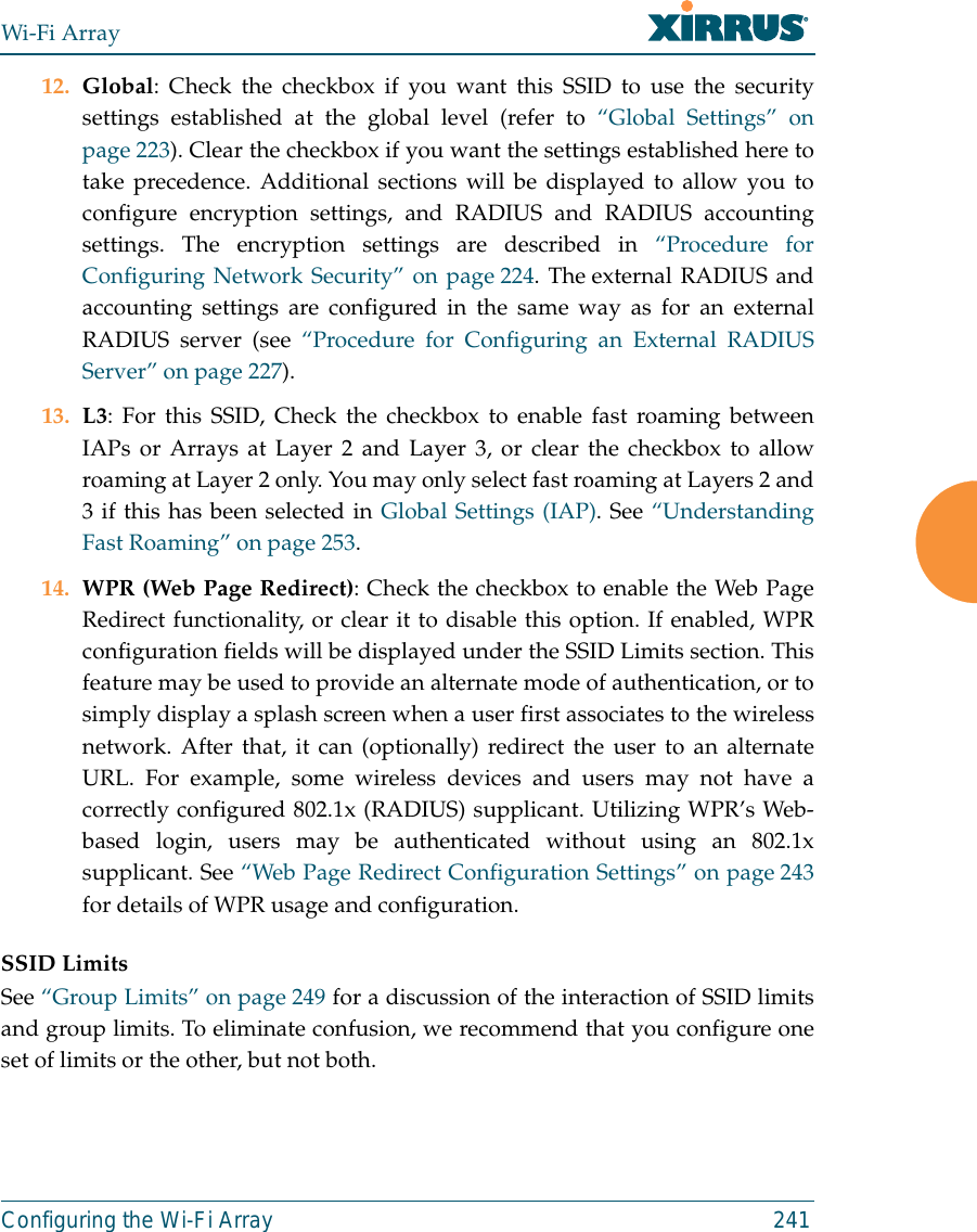
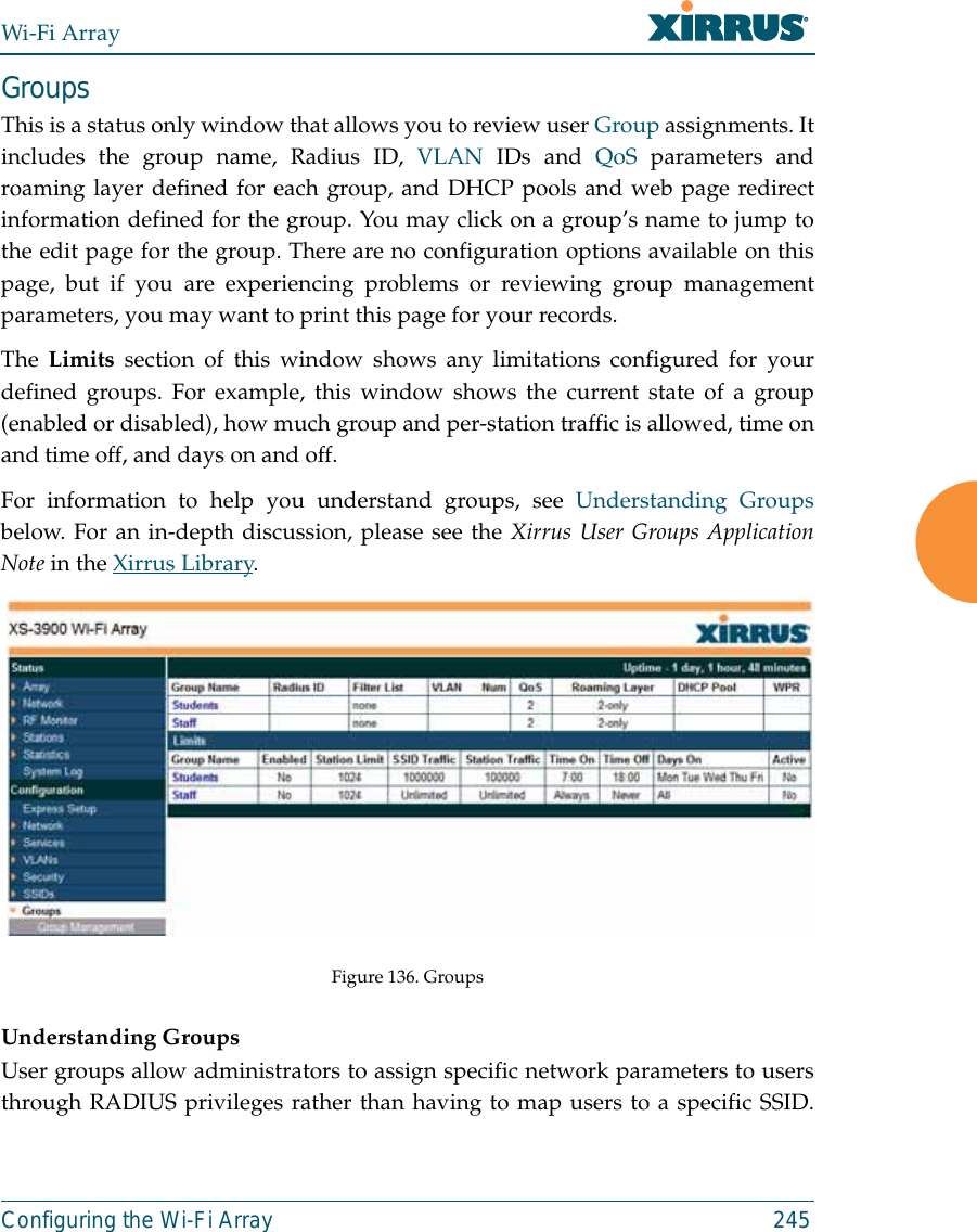
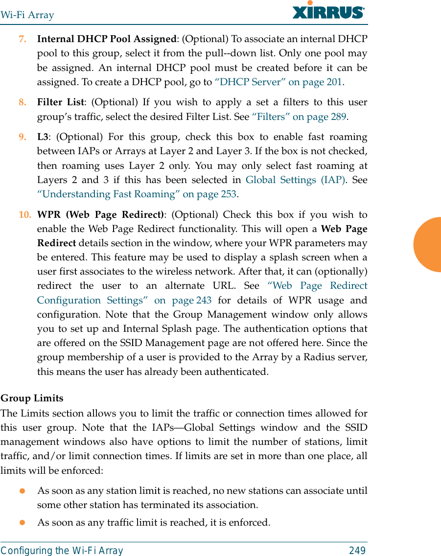
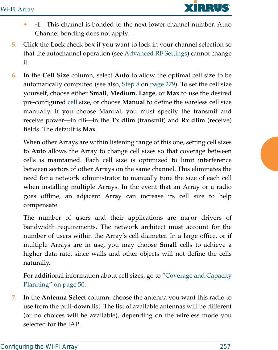
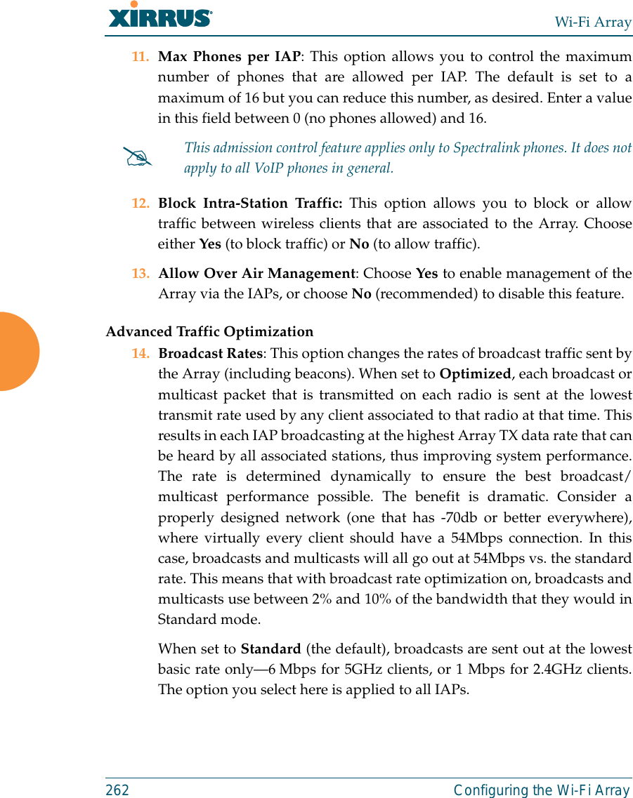
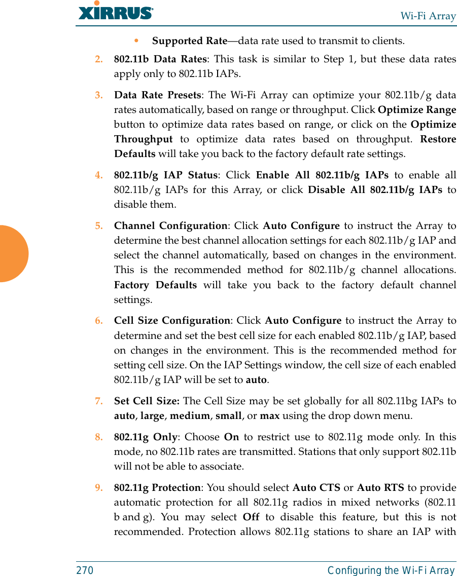
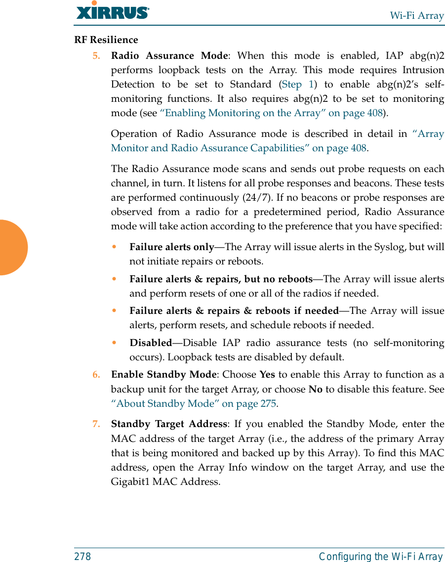
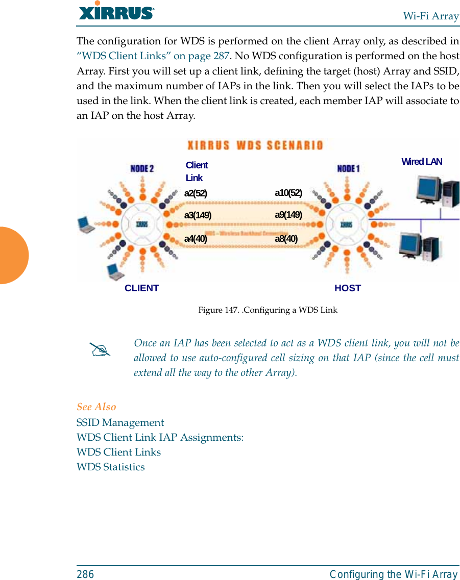
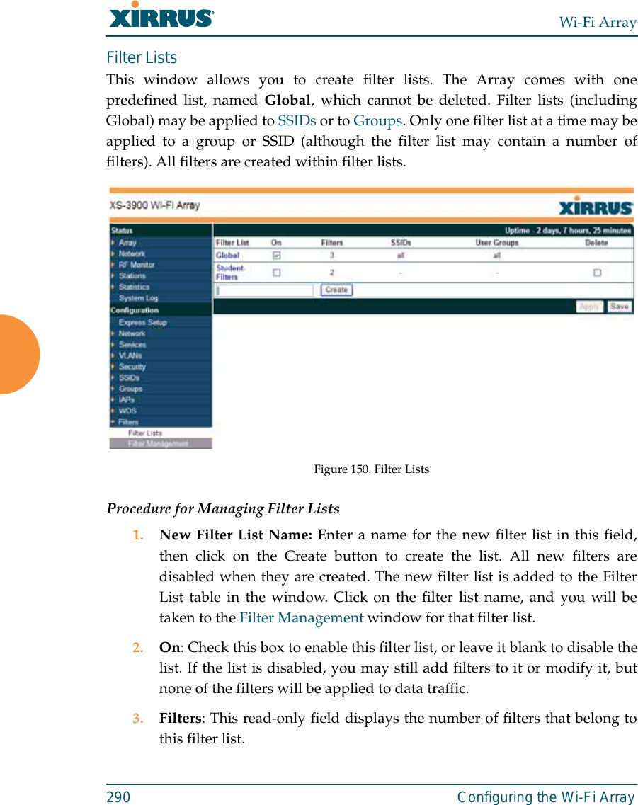
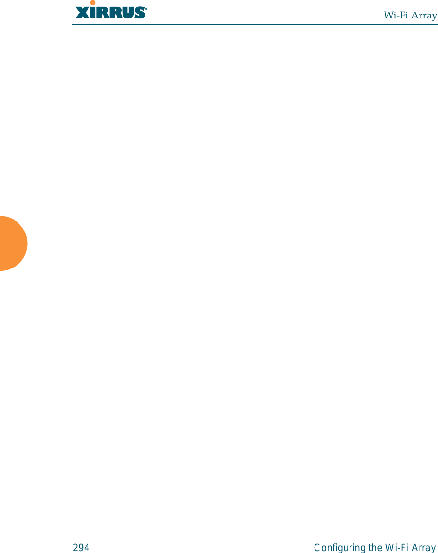
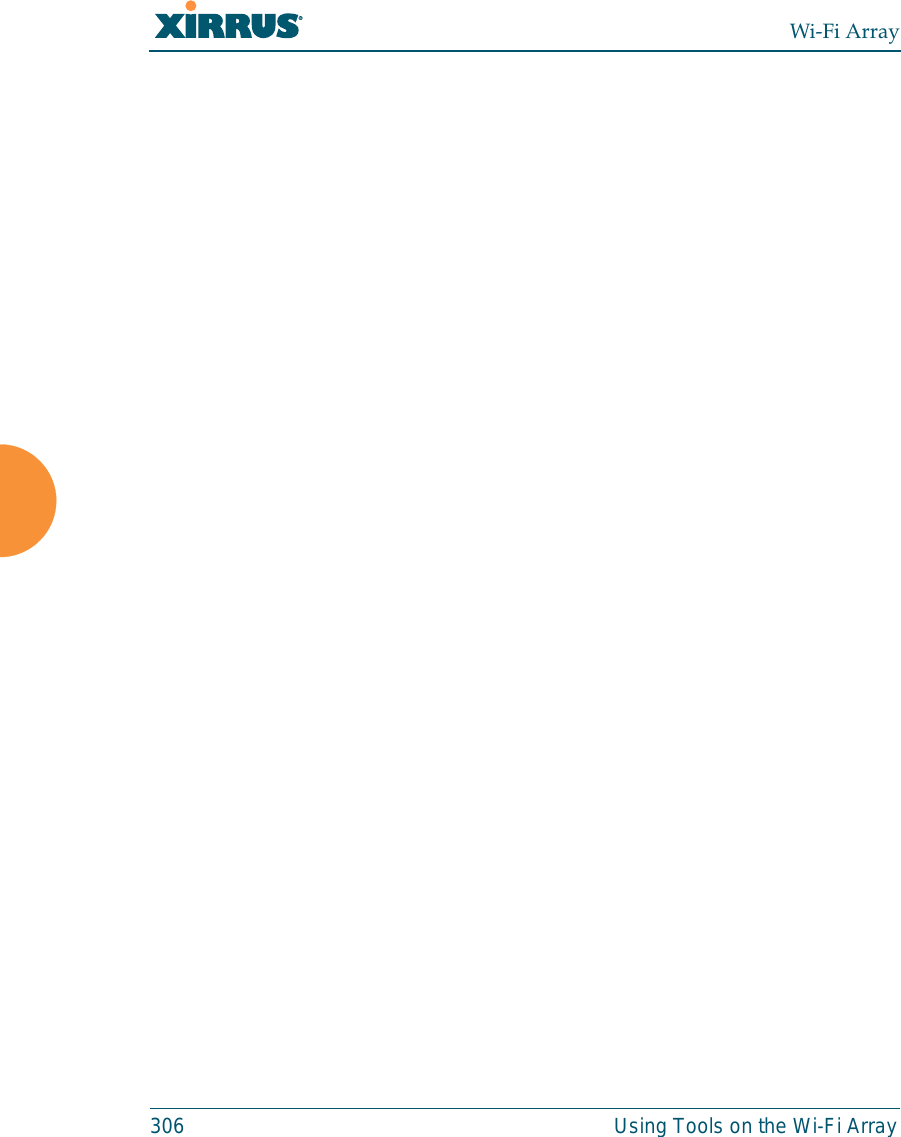
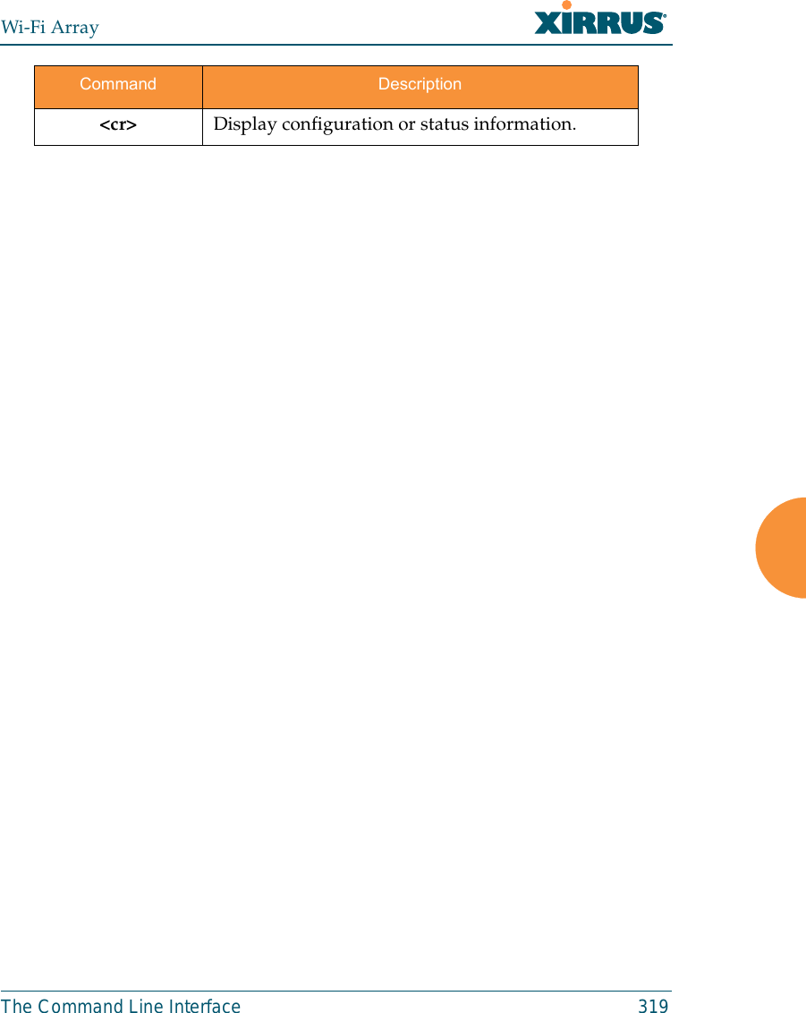
![Wi-Fi Array318 The Command Line Interfacestatistics CommandsThe following table shows the second level commands that are available with thetop level statistics command [Xirrus_Wi-Fi_Array# statistics].Command Descriptionethernet Display statistical data for all Ethernet interfaces.Ethernet Nameeth0, gig1, gig2Display statistical data for the defined Ethernet interface (either eth0, gig1 or gig2).FORMAT:statistics gig1 filter Display statistics for defined filters (if any).FORMAT:statistics filter [detail] filter-list Display statistics for defined filter list (if any).FORMAT:statistics filter <filter-list> iap Display statistical data for the defined IAP.FORMAT:statistics iap abgn4station Display statistical data about associated stations.FORMAT:statistics station billwvlan Display statistical data for the defined VLAN. You must use the VLAN number (not its name) when defining a VLAN.FORMAT:statistics vlan 1wds Display statistical data for the defined active WDS (Wireless Distribution System) links.FORMAT:statistics wds 1](https://usermanual.wiki/Cambium-Networks/XN12.C-Pages-226-to-350-from-ArrayGuide-Rel4-SS-Dec02-2008/User-Guide-1071267-Page-113.png)
![Wi-Fi Array320 The Command Line InterfaceConfiguration CommandsAll configuration commands are accessed by using the configure command at theroot command prompt (Xirrus_Wi-Fi_Array#). This section provides a briefdescription of each command and presents sample formats where deemednecessary. The commands are organized alphabetically. When inputtingcommands, be aware that all commands are case-sensitive.To see examples of some of the key configuration tasks and their associatedcommands, go to “Sample Configuration Tasks” on page 356.acl The acl command [Xirrus_Wi-Fi_Array(config)# acl] is used to configure theAccess Control List.Command Descriptionadd Add a MAC address to the list.FORMAT:acl add AA:BB:CC:DD:EE:FFdel Delete a MAC address from the list.FORMAT:acl del AA:BB:CC:DD:EE:FFdisable Disable the Access Control ListFORMAT:acl disableenable Enable the Access Control ListFORMAT:acl enablereset Delete all MAC addresses from the list.FORMAT:acl reset](https://usermanual.wiki/Cambium-Networks/XN12.C-Pages-226-to-350-from-ArrayGuide-Rel4-SS-Dec02-2008/User-Guide-1071267-Page-115.png)
![Wi-Fi ArrayThe Command Line Interface 321admin The admin command [Xirrus_Wi-Fi_Array(config-admin)#] is used to configurethe Administrator List.Command Descriptionadd Add a user to the Administrator List.FORMAT:admin add [userID]del Delete a user to the Administrator List.FORMAT:admin del [userID]edit Modify user in the Administrator List.FORMAT:admin edit [userID]radius Define a RADIUS server to be used for authenticating administrators.FORMAT:admin radius [disable | enable | off | on | timeout <seconds> | auth-type [PAP | CHAP]] admin radius [primary |secondary] port <portid> server [<ip-addr> | <host>] secret <shared-secret>reset Delete all users and restore the default user.FORMAT:admin reset](https://usermanual.wiki/Cambium-Networks/XN12.C-Pages-226-to-350-from-ArrayGuide-Rel4-SS-Dec02-2008/User-Guide-1071267-Page-116.png)
![Wi-Fi Array322 The Command Line Interfacecdp The cdp command [Xirrus_Wi-Fi_Array(config)# cdp] is used to configure theCisco Discovery Protocol.Command Descriptiondisable Disable the Cisco Discovery ProtocolFORMAT:cdp disableenable Enable the Cisco Discovery ProtocolFORMAT:cdp enablehold-time Select CDP message hold time before messages received from neighbors expire.FORMAT:cdp hold-time [# seconds]interval The Array sends out CDP announcements at this interval. FORMAT:cdp interval [# seconds] off Disable the Cisco Discovery ProtocolFORMAT:cdp offon Enable the Cisco Discovery ProtocolFORMAT:cdp on](https://usermanual.wiki/Cambium-Networks/XN12.C-Pages-226-to-350-from-ArrayGuide-Rel4-SS-Dec02-2008/User-Guide-1071267-Page-117.png)
![Wi-Fi ArrayThe Command Line Interface 323clear The clear command [Xirrus_Wi-Fi_Array(config)# clear] is used to clearrequested elements.Command Descriptionauthentication Deauthenticate a station.FORMAT:clear station [authenticated station]history Clear the history of CLI commands executed.FORMAT:clear history screen Clear the screen where you’re viewing CLI output.FORMAT:clear syslogstatistics Clear the statistics for a requested interface.FORMAT:clear statistics [eth0]syslog Clear all Syslog messages, but continue to log new messages.FORMAT:clear syslog](https://usermanual.wiki/Cambium-Networks/XN12.C-Pages-226-to-350-from-ArrayGuide-Rel4-SS-Dec02-2008/User-Guide-1071267-Page-118.png)
![Wi-Fi Array324 The Command Line Interfacecontact-info The contact-info command [Xirrus_Wi-Fi_Array(config)# contact-info] is usedfor managing administrator contact information.Command Descriptionemail Add an email address for the contact (must be in quotation marks).FORMAT:contact-info email [“contact@mail.com”]name Add a contact name (must be in quotation marks).FORMAT:contact-info name [“Contact Name”]phone Add a telephone number for the contact (must be in quotation marks).FORMAT:contact-info phone [“8185550101”]](https://usermanual.wiki/Cambium-Networks/XN12.C-Pages-226-to-350-from-ArrayGuide-Rel4-SS-Dec02-2008/User-Guide-1071267-Page-119.png)
![Wi-Fi ArrayThe Command Line Interface 325date-time The date-time command [Xirrus_Wi-Fi_Array(config-date-time)#] is used toconfigure the date and time parameters. Your Array supports the Network TimeProtocol (NTP) in order to ensure that the Array’s internal time is accurate. NTP isset to UTC time by default; however, you can set the time zone so that your Arraywill display local time. This is done by defining an offset from the UTC value. Forexample, Pacific Standard Time is 8 hours behind UTC time, so the offset fromUTC time would be -8.Command Descriptiondst_adjust Enable adjustment for daylight savings.FORMAT:date-time dst_adjustno Disable daylight savings adjustment.FORMAT:date-time no dst_adjustntp Enable the NTP server.FORMAT:date-time ntp on (or off to disable)offset Set an offset from Greenwich Mean Time.FORMAT:date-time no dst_adjustset Set the date and time for the Array.FORMAT:date-time set [10:24 10/23/2007]timezone Configure the time zone.FORMAT:date-time timezone [-8]](https://usermanual.wiki/Cambium-Networks/XN12.C-Pages-226-to-350-from-ArrayGuide-Rel4-SS-Dec02-2008/User-Guide-1071267-Page-120.png)
![Wi-Fi Array326 The Command Line Interfacedhcp-server The dhcp-server command [Xirrus_Wi-Fi_Array(config-dhcp-server)#] is used toadd, delete and modify DHCP pools.Command Descriptionadd Add a DHCP pool.FORMAT:dhcp-server add [dhcp pool]del Delete a DHCP pool.FORMAT:dhcp-server del [dhcp pool]edit Edit a DHCP poolFORMAT:dhcp-server edit [dhcp pool]reset Delete all DHCP pools.FORMAT:dhcp-server reset](https://usermanual.wiki/Cambium-Networks/XN12.C-Pages-226-to-350-from-ArrayGuide-Rel4-SS-Dec02-2008/User-Guide-1071267-Page-121.png)
![Wi-Fi ArrayThe Command Line Interface 327dns The dns command [Xirrus_Wi-Fi_Array(config-dns)#] is used to configure yourDNS parameters.Command Descriptiondomain Enter your domain name.FORMAT:dns domain [www.mydomain.com]server1 Enter the IP address of the primary DNS server.FORMAT:dns server1 [1.2.3.4]server2 Enter the IP address of the secondary DNS server.FORMAT:dns server1 [2.3.4.5]server3 Enter the IP address of the tertiary DNS server.FORMAT:dns server1 [3.4.5.6]](https://usermanual.wiki/Cambium-Networks/XN12.C-Pages-226-to-350-from-ArrayGuide-Rel4-SS-Dec02-2008/User-Guide-1071267-Page-122.png)
![Wi-Fi Array328 The Command Line Interfacefile The file command [Xirrus_Wi-Fi_Array(config-file)#] is used to manage files.Command Descriptionactive-image Validate and commit a new array software image. backup-image Validate and commit a new backup software image. check-image Validate a new array software image. chkdsk Check flash file system.copy Copy a file to another file.FORMAT:file copy [sourcefile destinationfile]dir List the contents of a directory.FORMAT:file dir [directory]erase Delete a file from the FLASH file system.FORMAT:file erase [filename]format Format flash file system.ftp Open an FTP connection with a remote server. Files will be transferred in binary mode. FORMAT:file ftp host {<hostname> |<ip>} [port <port_#>] [user {anonymous | <username> password <passwd> } ] { put <source_file> [<dest_file>] | get <source_file> [<dest_file>] }Note: Any time you transfer any kind of software image file for the Array, it must be transferred in binary mode, or the file may be corrupted. list List the contents of a file.FORMAT:file list [filename]](https://usermanual.wiki/Cambium-Networks/XN12.C-Pages-226-to-350-from-ArrayGuide-Rel4-SS-Dec02-2008/User-Guide-1071267-Page-123.png)
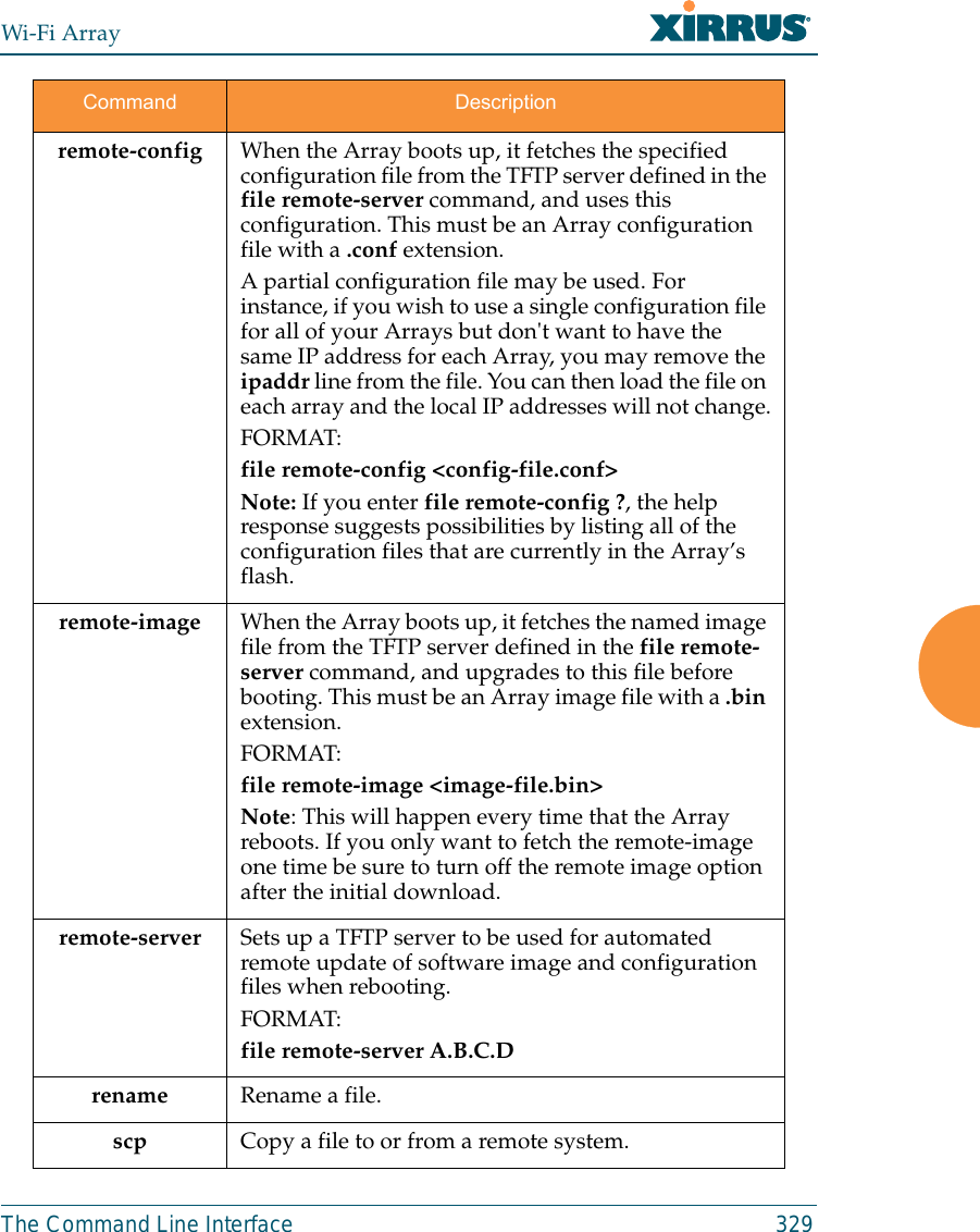
![Wi-Fi Array330 The Command Line Interfacetftp Open a TFTP connection with a remote server.FORMAT:file tftp host {<hostname> |<ip>} [port <port_#>] [user {anonymous | <username> password <passwd> } ] { put <source_file> [<dest_file>] | get <source_file> [<dest_file>] }Note: Any time you transfer any kind of software image file for the Array, it must be transferred in binary mode, or the file may be corrupted. Command Description](https://usermanual.wiki/Cambium-Networks/XN12.C-Pages-226-to-350-from-ArrayGuide-Rel4-SS-Dec02-2008/User-Guide-1071267-Page-125.png)