Cambium Networks XN12 WIRELESS LAN ARRAY User Manual
Xirrus, Inc. WIRELESS LAN ARRAY
Contents
- 1. Users Manual 1of5
- 2. Users Manual 2of5
- 3. Users Manual 3of5
- 4. Users Manual 4of5
- 5. Users Manual 5of5
- 6. A Pages 1 to 125 from ArrayGuide Rel4 SS Dec02 2008
- 7. B Pages 126 to 225 from ArrayGuide Rel 4 SS Dec02 2008
- 8. C Pages 226 to 350 from ArrayGuide Rel4 SS Dec02 2008
- 9. D Pages 351 to 496 from ArrayGuide Rel4 SS Dec02 2008 Small 5
- 10. XN Guide small 1 of 5 revised
B Pages 126 to 225 from ArrayGuide Rel 4 SS Dec02 2008
Wi-Fi Array
106 Installing the Wi-Fi Array
Mount the Array
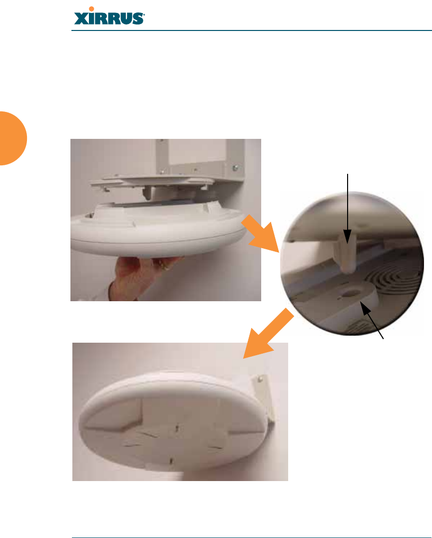
8. Mount the Wi-Fi Array to the Wall Mounting Bracket by positioning the
key post (on the underside of the mounting bracket) into the key
receptacle on the underside of the Array.
When the key post is properly located, gently turn the Array in a
clockwise direction to secure the Array to the mounting plate.
Figure 55. Mounting the Array on a Wall
Key Post (Mounting Bracket)
Receptacle
Wi-Fi Array
Installing the Wi-Fi Array 107
Removing the Array
To remove the Array from the Wall Mount Assembly, simply apply a little upward
pressure to the Array, then gently turn the Array in a counterclockwise direction
to release the unit from the bracket.
See Also
Installation Workflow
Installing Your Wi-Fi Array
Mounting Array on a Wall (All models except 4-port Arrays)
Mounting the Array on a Ceiling
Securing the Array
Powering Up the Wi-Fi Array
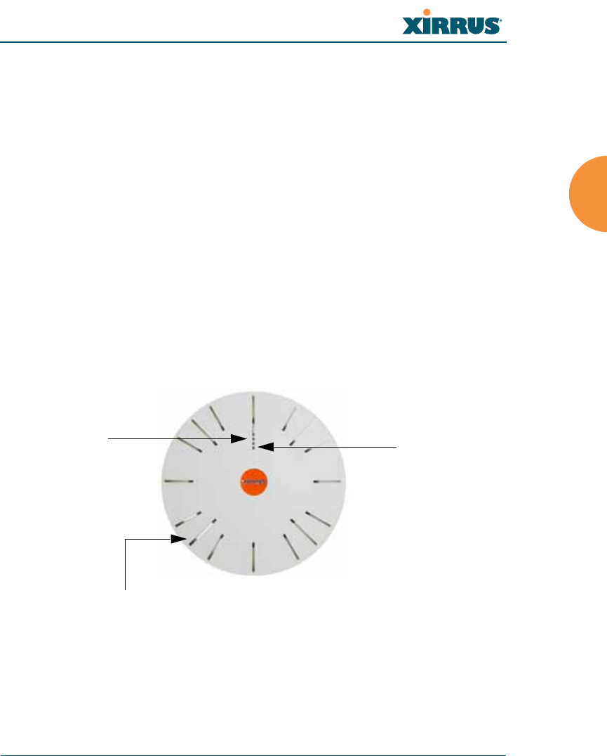
When powering up, the Array follows a specific sequence of LED patterns
showing the boot progress, and following a successful boot will provide extensive
status information.
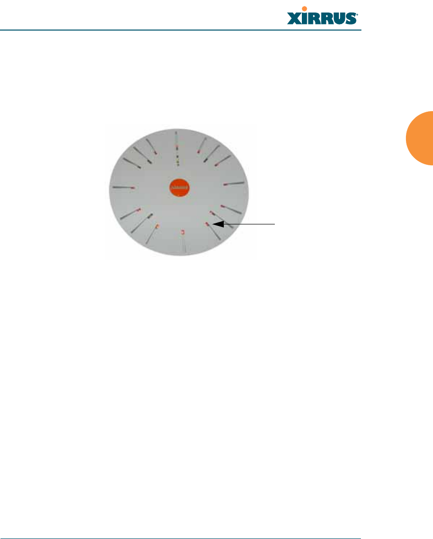
Figure 56. LED Locations (XS-3900)
Array LED settings may be altered or disabled entirely for diagnostic purposes or
for personal preference. Changes are made via the Array’s Command Line
Interface or the Web Management Interface—refer to “LED Settings” on page 283.
Status LED
Ethernet Activity
LEDs
IAP LEDs (x16)

Wi-Fi Array
108 Installing the Wi-Fi Array
Array LED Operating Sequences
Use the following tables to review the operating sequences of the Array’s LEDs.
LED Boot Sequence
The normal boot LED sequence is as follows:
Array Activity Status LED IAP LEDs
Power ON Blinking GREEN All OFF
Boot loader power ON
self-test Blinking GREEN All ON
Image load from
compact FLASH Blinking GREEN Spinning pattern
(rotate all to ON, then
all to OFF)
Image load failure Blinking RED All OFF
Hand off to ArrayOS Solid GREEN All OFF
System software
initialization Solid GREEN Walking pattern
(LED rotating one
position per second)
Up and running Solid GREEN ON for IAPs that are
up, and OFF for IAPs
that are down

Wi-Fi Array
Installing the Wi-Fi Array 109
LED Operation when Array is Running
The normal LED operation when the Array is running is as follows:
See Also
Installation Prerequisites
Installation Workflow
Installing Your Wi-Fi Array
LED Status Reason
IAP LED is OFF IAP is down
IAP LED is solid ON IAP is up, but no associations and
no traffic
IAP LED heartbeat IAP is up, with stations
associated but no traffic
IAP LED flashing
Flashing at 10 Hz
Flashing at 5 Hz
Flashing at 2.5 Hz
IAP is up, passing traffic
Traffic > 1500 packets/sec
Traffic > 150 packets/sec
Traffic > 1 packet/sec
IAP LED is GREEN IAP is operating in the 2.4 GHz
band
IAP LED is ORANGE IAP is operating in the 5 GHz
band
IAP LED flashing ORANGE to
GREEN at 1 Hz IAP abg(n)2 is in monitor mode
(standard intrude detect)
Ethernet LEDs are dual color
Ethernet LED is ORANGE
Ethernet LED is GREEN
Transferring data at 1 Gbps
Transferring data at 10/100 Mbps
Wi-Fi Array
110 Installing the Wi-Fi Array
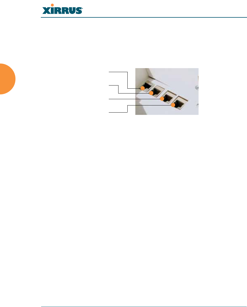
Establishing Communication with the Array
The Array can be configured through the Command Line Interface (CLI) or the
graphical Web Management Interface (WMI). You can use the CLI via the serial
management port, the Fast Ethernet port, or either of the Gigabit Ethernet ports.
You can use the WMI via any of the Array’s Ethernet ports.
Figure 57. Network Interface Ports
Using the Serial Port
If using the serial port to make your connection, use serial settings of 8 bits, no
parity, no flow control, 1 stop bit (8N1) and a speed setting of 115200 baud. Use
the communication package of your choice.
Using the Ethernet Ports
By default, the Array's Ethernet interfaces use DHCP to obtain an IP address. If
the Array is booted and does not receive DHCP addresses on either the Fast
Ethernet or Gigabit Ethernet ports, the Fast Ethernet port will default to an IP
address of 10.0.1.1 and both Gigabit Ethernet ports will default to 10.0.2.1. If the
Array is connected to a network that provides DHCP addresses, the IP address
can be determined by the following two methods:
1. Examine the DHCP tables on the server and find the addresses assigned
to the Array (Xirrus MAC addresses begin with 000F7D).
2. Query the Array using the CLI via the serial port. Use the show ethernet
command to view the IP addresses assigned to each port.
Serial
Fast Ethernet
Gigabit 1
Gigabit 2

Wi-Fi Array
Installing the Wi-Fi Array 111
Logging In
When logging in to the Array, use the default user name and password—the
default user name is admin, and the default password is admin.
See Also
Installation Workflow
Performing the Express Setup Procedure
Powering Up the Wi-Fi Array
Wi-Fi Array
112 Installing the Wi-Fi Array
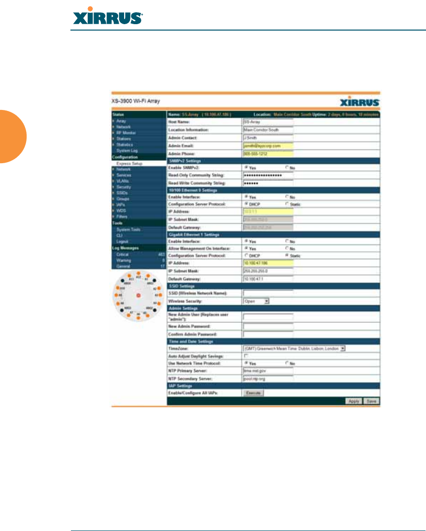
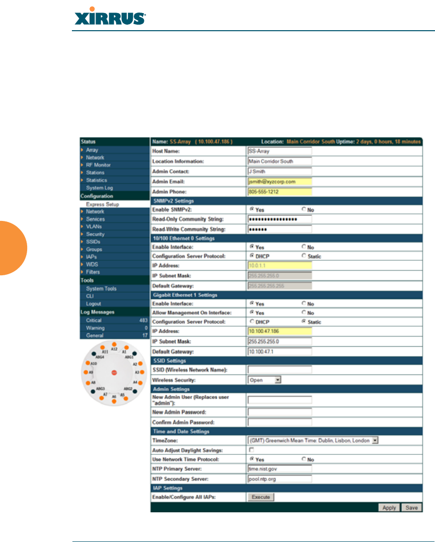
Performing the Express Setup Procedure
The Express Setup procedure establishes global configuration settings that enable
basic Array functionality. Changes made in this window will affect all radios.
Figure 58. Express Setup
Procedure for Performing an Express Setup
1. Host Name: Specify a unique host name for this Array. The host name is
used to identify the Array on the network. Use a name that will be
meaningful within your network environment, up to 64 alphanumeric
characters. The default is Xirrus-WiFi-Array.

Wi-Fi Array
Installing the Wi-Fi Array 113
2. Location Information: Enter a brief but meaningful description that
accurately defines the physical location of the Array. In an environment
where multiple units are installed, clear definitions for their locations are
important if you want to identify a specific unit.
3. Admin Contact: Enter the name and contact information of the person
who is responsible for administering the Array at the designated location.
4. Admin Email: Enter the email address of the admin contact you entered
in Step 3.
5. Admin Phone: Enter the telephone number of the admin contact you
entered in Step 3.
6. Configure SNMP: Select whether to Enable SNMP on the Array, and set
the SNMP Read-Write Community String. The factory default value for
this is xirrus. If you are using the Xirrus Management System (XMS), this
string must match the string used by XMS.
7. Configure the Fast Ethernet (10/100 Megabit), Gigabit 1 and Gigabit 2
network interfaces. The fields for each of these interfaces are the same,
and include:
a. Enable Interface: Choose Yes to enable this network interface, or
choose No to disable the interface.
b. Allow Management on Interface: Choose Yes to allow management
of the Array via this network interface, or choose No to deny all
management privileges for this interface.
c. Configuration Server Protocol: Choose DHCP to instruct the Array
to use DHCP to assign IP addresses to the Array’s Ethernet interfaces,
or choose Static if you intend to enter IP addresses manually. If you
choose the Static IP option, you must enter the following information:
zIP Address: Enter a valid IP address for this Array. To use any of
the remote connections (Web, SNMP, or SSH), a valid IP address
must be used.
zIP Subnet Mask: Enter a valid IP address for the subnet mask
(the default is 255.255.255.0). The subnet mask defines the

Wi-Fi Array
114 Installing the Wi-Fi Array
number of IP addresses that are available on the routed subnet
where the Array is located.
zDefault Gateway: Enter a valid IP address for the default
gateway. This is the IP address of the router that the Array uses
to forward data to other networks.
8. SSID Settings: This section specifies the wireless network name and
security settings.
a. SSID (Wireless Network Name): The SSID (Service Set Identifier) is
a unique name that identifies a wireless network. All devices
attempting to connect to a specific WLAN must use the same SSID.
The default for this field is “xirrus.”
For additional information about SSIDs, go to the Multiple SSIDs
section of “Frequently Asked Questions” on page 400.
b. Wireless Security: Select the desired wireless security scheme (Open,
WEP, WPA, WPA2, or WPA-Both). WPA2 is recommended for the
best Wi-Fi security.
•Open—This option offers no data encryption and is not
recommended, though you might choose this option if clients are
required to use a VPN connection through a secure SSH utility,
like PuTTy.
•WEP (Wired Equivalent Privacy)—An optional IEEE 802.11
function that offers frame transmission privacy similar to a wired
network. WEP generates secret shared encryption keys that both
source and destination stations can use to alter frame bits to
avoid disclosure to eavesdroppers.
•WPA (Wi-Fi Protected Access)—A Wi-Fi Alliance standard that
contains a subset of the IEEE 802.11i standard, using TKIP or AES
as an encryption method and 802.1x for authentication.
•WPA2 (Wi-Fi Protected Access 2)—WPA2 is the follow-on
security method to WPA for wireless networks and provides
stronger data protection and network access control. It offers
Enterprise and consumer Wi-Fi users with a high level of

Wi-Fi Array
Installing the Wi-Fi Array 115
assurance that only authorized users can access their wireless
networks. Like WPA, WPA2 is designed to secure all versions of
802.11 devices, including 802.11a, 802.11b, 802.11g, and 802.11n,
multi-band and multi-mode.
•WPA-Both (WPA and WPA2)—This option makes use of both
WPA and WPA2.
For more information about security, including a full review of all
security options and settings, go to “Understanding Security” on
page 208.
c. Wireless Key/Passphrase: Depending on the wireless security
scheme you selected, enter a unique WEP key or WPA passphrase.
d. Confirm Key/Passphrase: If you entered a WEP key or WPA
passphrase, confirm it here.
9. Admin Settings: This section allows you to change the default password
for the Array. Note that the Array also offers the option of authenticating
administrators using a RADIUS server (see “Admin Management” on
page 213).
a. New Admin Password: If desired, enter a new administration
password for managing this Array. Choose a password that is not
obvious, and one that you can remember. If you forget your
password, you must reset the Array to its factory defaults so that the
password is reset to admin (its default setting).
b. Confirm Admin Password: If you entered a new administration
password, confirm the new password here.
10. Time and Date Settings: This section specifies an optional time (NTP -
Network Time Protocol) server or modifies the system time if you’re not
using a server.
a. Time Zone: Select your time zone from the choices available in the
pull-down list.
b. Use Network Time Protocol: Check this box if you want to use an
NTP server to synchronize the Array’s clock. This ensures that Syslog

Wi-Fi Array
116 Installing the Wi-Fi Array
time-stamping is maintained across all units. Without an NTP server
assigned (no universal clock), each Array will use its own internal
clock and stamp times accordingly, which may result in
discrepancies. If you check Yes, the NTP server fields are displayed. If
you don’t want to use an NTP server, leave this box unchecked
(default) and set the system time on the Array manually.
c. NTP Primary Server: If you are using NTP, enter the IP address or
domain name of the NTP server.
d. NTP Secondary Server: Enter the IP address or domain name of an
optional secondary NTP server to be used in case the Array is unable
to contact the primary server.
e. Set Time (hrs:min:sec): If you are not using NTP, check this box if
you want to adjust the current system time. When the box is checked,
the time fields become active. Enter the revised time (hours, minutes,
seconds, am/pm) in the corresponding fields. If you don’t want to
adjust the current time, this box should be left unchecked (default).
f. Set Date (month/day/year): If you are not using NTP, check this box if
you want to adjust the current system date. When the box is checked,
the date fields become active. Enter the revised date (month, day and
year) in the corresponding fields. If you don’t want to adjust the
current date, this box should be left unchecked (default).
g. Auto Adjust Daylight Savings: If you are not using NTP, check this
box if you want the system to adjust for daylight savings
automatically, otherwise leave this box unchecked (default).
Wi-Fi Array
Installing the Wi-Fi Array 117
11. IAP Settings:
Enable/Configure All IAPs: Click on the Execute button to enable and
auto configure all IAPs (a message displays the countdown time—in
seconds—to complete the auto-configuration task). When an IAP is
enabled, its LED is switched on.
Figure 59. LEDs are Switched On
12. Click on the Apply button to apply the new settings to this session
13. Click on the Save button to save your changes (otherwise your new
settings will not take effect).
This ends the Express Setup procedure.
See Also
Establishing Communication with the Array
Installation Prerequisites
Installation Workflow
Logging In
Multiple SSIDs
Security
LED on

Wi-Fi Array
118 Installing the Wi-Fi Array

Wi-Fi Array
The Web Management Interface 119
The Web Management Interface
This topic provides an overview of the Xirrus Wi-Fi Array’s embedded Web
Management Interface (WMI), used for establishing your network’s configuration
settings and wireless operating parameters. It also includes login instructions.
The following topics are discussed:
zAn Overview
zStructure of the WMI
zUser Interface
zLogging In
zApplying Configuration Changes
Wi-Fi Array
120 The Web Management Interface
An Overview
The WMI is an easy-to-use graphical interface to your Wi-Fi Array. It allows you
to configure the product to suit your individual requirements and ensure that the
unit functions efficiently and effectively.
Figure 60. Web Management Interface

Wi-Fi Array
The Web Management Interface 121
Structure of the WMI
The content of the WMI is organized by function and hierarchy, shown in the
following table. Click on any item below to jump to the referenced destination.
Status Windows
Array Status Windows
Array Summary
Array Information
Array Configuration
Admin History
Network Status Windows
Network Map
Spanning Tree Status
Routing Table
ARP Table
DHCP Leases
Connection Tracking/NAT
CDP Neighbors
RF Monitor Windows
IAPs
Spectrum Analyzer
Intrusion Detection
Station Status Windows
Stations
Location Map
RSSI
Signal-to-Noise Ratio (SNR)
Noise Floor
Max by IAP
Configuration Windows
Express Setup
Network
Network Interfaces
DNS Settings
CDP Settings
Configuration Windows (cont’d)
Services
Time Settings (NTP)
NetFlow
System Log
SNMP
DHCP Server
VLANs
VLAN Management
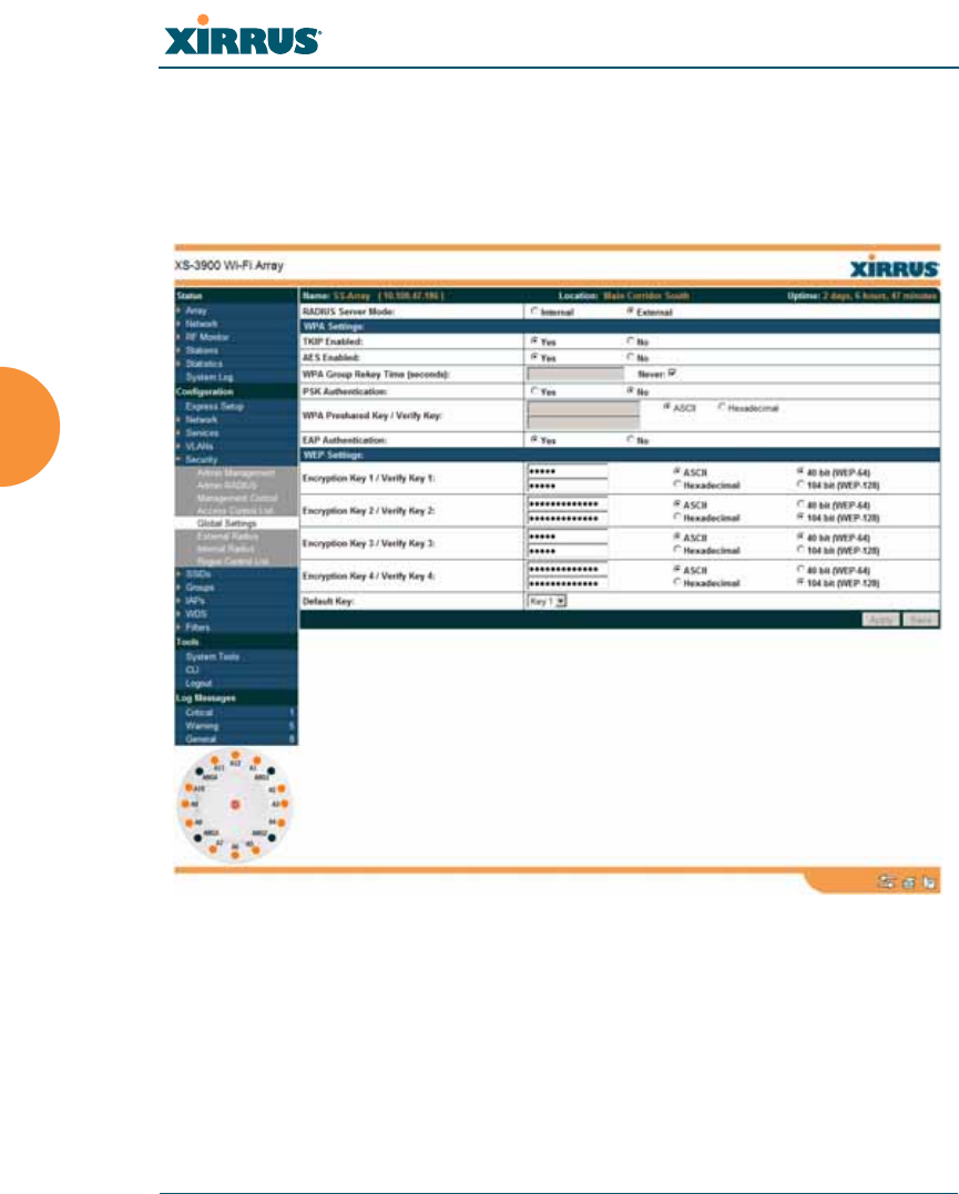
Security
Admin Management
Admin RADIUS
Management Control
Access Control List
Global Settings
External Radius
Internal Radius
Rogue Control List
SSIDs
SSID Management
Groups
Group Management
IAPs
IAP Settings
Global Settings (IAP)
Global Settings .11a
Global Settings .11bg
Global Settings .11n
Advanced RF Settings
LED Settings
WDS
WDS Client Links
Filters
Filter Lists
Filter Management

Wi-Fi Array
122 The Web Management Interface
Statistics Windows
IAP Statistics Summary
Per-IAP Statistics
Network Statistics
VLAN Statistics
WDS Statistics
Filter Statistics
Station Statistics
Per-Station Statistics
System Log Window
Tool Windows
System Tools
CLI
Logout
Wi-Fi Array
The Web Management Interface 123
User Interface
The WMI has been designed with simplicity in mind, making navigation quick
and easy. In the following example, you’ll see that windows are divided into left
and right frames.
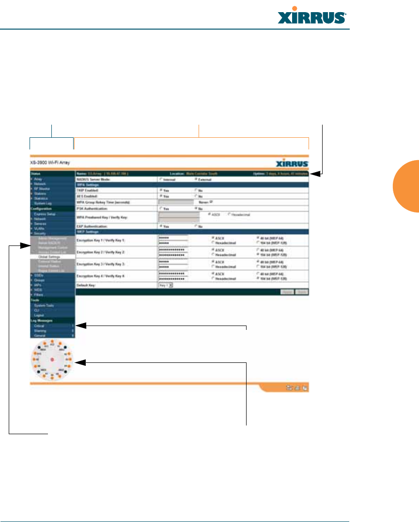
Figure 61. WMI: Frames
Left frame Right frame Array info
Pull-down menu Click to configure/view statistics
Message counters
Wi-Fi Array
124 The Web Management Interface
The left frame contains three main elements:
zConfiguration menu organized by function (for example, radio interfaces,
security, etc.). Click the heading to display a summary of its current
configuration, as well as an associated pull-down menu.
zThree counters are located at the bottom of the menu. They provide a
running total of messages generated by the ArrayOS Syslog subsystem
during your session—organized into Critical, Warning, and General
messages. Click on a counter to display the associated Syslog messages.
Messages at the selected level or higher will be shown.
zThe Array representation contains shortcut links. Click a radio to view
statistics for it. Click the center of the Array to display the IAP Settings
window, which allows you to configure the Array’s radios.
The right frame displays the status information or configuration parameters for
the Wi-Fi Array. This is where you review the Array’s current status and activity
or input data (if you want to make changes). The green Array information bar at
the top of the frame describes the Array—the Name and IP address allow you to
quickly confirm that WMI is connected to the correct Array. The current Uptime
since the last reboot is also shown.
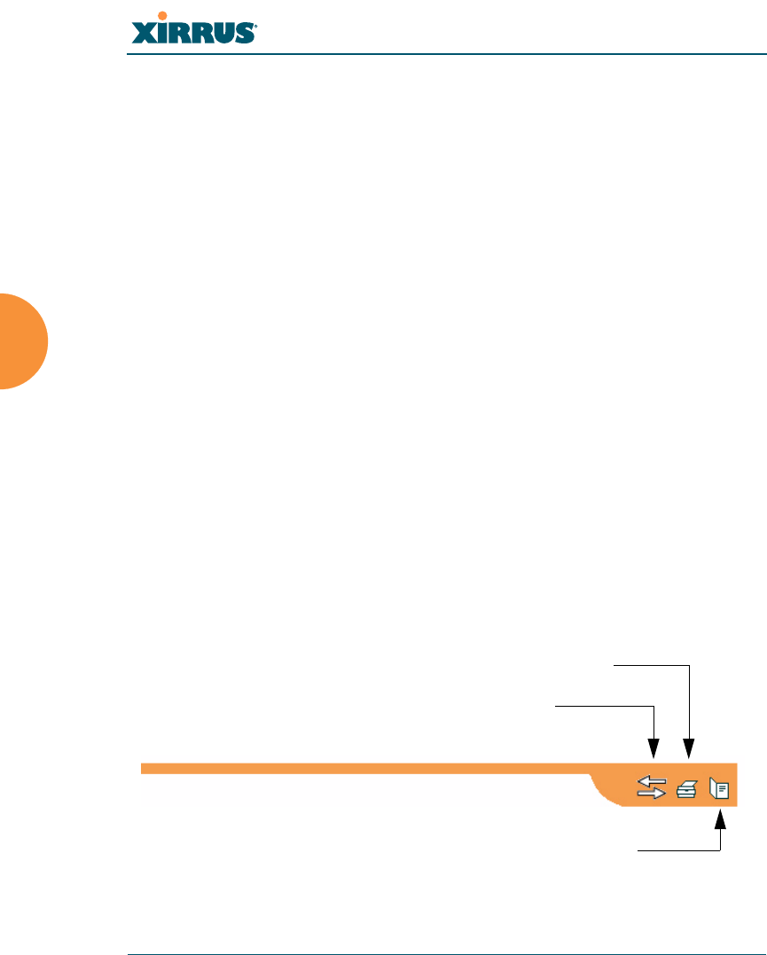
Utility Buttons
At the bottom of each window you will find a set of useful buttons—a Feedback
button, a Print button and a Help button.
Figure 62. WMI: Utility Buttons
Print button
Help button
Feedback button
Wi-Fi Array
The Web Management Interface 125
zClick on the Feedback button to generate a Web page that allows you to
submit your comments to Xirrus, Inc. You can also access the feedback
page at http://www.xirrus.com/public/feedback/. Refer to Figure 63 on
page 125 to see a sample of the feedback form.
zClick on the Print button to send a print file of the active window to your
local printer.
zClick on the Help button to access the Array’s online help system.
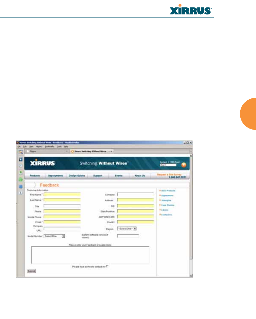
Submitting Your Comments
When submitting comments via the Feedback button, ensure that you provide as
much detail as possible, including your contact information, the product model
number that the comment relates to, and the ArrayOS software version (if
known). When finished, click on the Submit button to submit your comment.
Figure 63. Feedback Form
Wi-Fi Array
126 The Web Management Interface
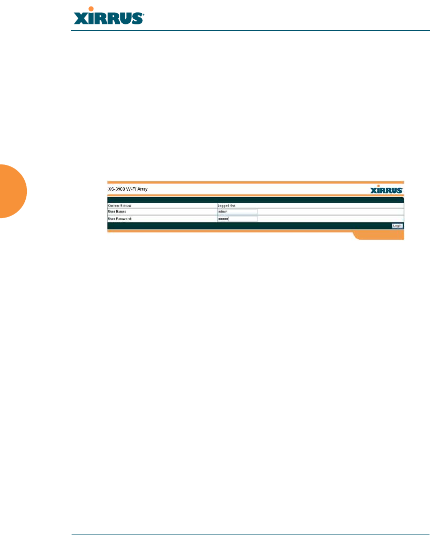
Logging In
Use this procedure to log in to the WMI via your Web browser.
1. Establish a network connection and open your Web browser.
2. Connect to the Wi-Fi Array via its default IP address (10.0.2.1 for both
Gigabit 1 and Gigabit 2 Ethernet ports) or via a DHCP assigned IP
address.
3. To log in to the Array’s Web Management Interface, enter admin when
prompted for a user name and password.
Figure 64. Logging In to the Wi-Fi Array
Applying Configuration Changes
When you have defined all your settings in any WMI configuration window, you
must click on the Apply button for the changes to take effect in the current
session, or click on the Save button to apply changes to this session and write
your changes, so they will be preserved after a reboot.
Character Restrictions
When inputting strings in the WMI (for example, assigning SSIDs, host name,
password, etc.), use only common alphanumeric characters. Do not use any of the
following characters:
&<>' “/ \
See Also
Key Features and Benefits
Wi-Fi Array Product Overview

Wi-Fi Array
Viewing Status on the Wi-Fi Array 127
Viewing Status on the Wi-Fi
Array
These windows provide status information and statistics for your Array using the
product’s embedded Web Management Interface (WMI). You cannot make
configuration changes to your Array from these windows. The following topics
have been organized into functional areas that reflect the flow and content of the
Status section of the navigation tree in the left frame of the WMI.
z“Array Status Windows” on page 127
z“Network Status Windows” on page 134
z“RF Monitor Windows” on page 141
z“Station Status Windows” on page 149
z“Statistics Windows” on page 163
z“System Log Window” on page 171
Configuration and Tools windows are not discussed here. For information on
these windows, please see:
z“Configuring the Wi-Fi Array” on page 173
z“Using Tools on the Wi-Fi Array” on page 295
Array Status Windows
The following Array Status windows are available:
zArray Summary—displays information on the configuration of all Array
interfaces, including IAPs.
zArray Information—provides version/serial number information for all
Array components.
zArray Configuration—shows all configuration information for the Array
in text format.
zAdmin History—shows all current and past logins since the last reboot.
Wi-Fi Array
128 Viewing Status on the Wi-Fi Array
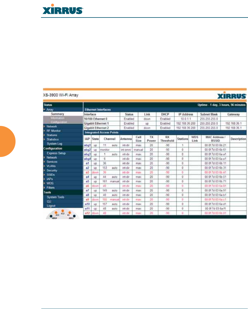
Array Summary
This is a status only window that provides a snapshot of the global configuration
settings for all Wi-Fi Array network interfaces and IAPs. You must go to the
appropriate configuration window to make changes to any of the settings
displayed here—configuration changes cannot be made from this window.
Clicking on an interface or IAP will take you to the proper window for making
configuration changes.
Figure 65. Array Summary

Wi-Fi Array
Viewing Status on the Wi-Fi Array 129
Content of the Array Summary Window
The Array Summary window is sub-divided into the Ethernet Interfaces section
and the Integrated Access Points (radio) section, providing you with the
following information:
zEthernet Interfaces Section
This section provides information about network interface devices. To
make configuration changes to these devices, go to “Network Interfaces”
on page 181.
•Interface: Lists the network interfaces that are available on the Array
(10/100 Ethernet 0, Gigabit Ethernet 1 and Gigabit Ethernet 2).
•Status: Shows the current state of each interface, either enabled or
disabled.
•Link: Shows whether the link on this interface is up or down.
•DHCP: Shows whether DHCP on this port is enabled or disabled.
•IP Address: Shows the current IP address assigned to each network
interface device.
•Subnet Mask: Shows the subnet mask, which defines the number of
IP addresses that are available on the routed subnet where the Array
is located.
•Gateway: Shows the IP address of the router that the Array uses to
transmit data to other networks.
zIntegrated Access Points Section
This section provides information about the Integrated Access Points
(IAPs) that are contained within the Array. How many IAPs are listed
depends on which product model you are using (16 IAPs for the XN16,
XS16, or XS-3900, 12 IAPs for the XN12, or XS12, 8 IAPs for the XN8, XS8,
or XS-3700, and 4 IAPs for the XN4, XS4 or XS-3500). To make
configuration changes to these IAPs, go to “IAP Settings” on page 254.
•IAP: Lists the IAPs that are available on the Array.
Wi-Fi Array
130 Viewing Status on the Wi-Fi Array
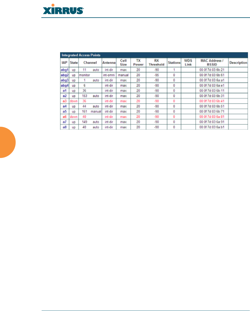
•State: Shows the current state of each IAP, either up or down. IAPs
that are down are shown in RED. Figure 66 shows an example where
IAP a3 is down.
Figure 66. Disabled IAP (Partial View)
•Channel: Shows which channel each IAP is using, and the channel
setting. To avoid co-channel interference, adjacent radios should not
be using adjacent channels. To make channel selections for a specific
IAP, go to “IAP Settings” on page 254.
•Antenna: Shows which antenna is being used by each IAP.
•Cell Size: Indicates which cell size setting is currently active for each
IAP—small, medium, large, max, automatic, or manually defined by
you. The cell size of an IAP is a function of its transmit power and
determines the IAP’s overall coverage. To define cell sizes, go to “IAP
Settings” on page 254. For additional information about cell sizes and
the importance of planning for and defining the optimum cell sizes
for your Array, go to “Coverage and Capacity Planning” on page 50.

Wi-Fi Array
Viewing Status on the Wi-Fi Array 131
Figure 67. IAP Cells
•Tx Power: Shows the transit power for each IAP.
•Rx Threshold: Shows the receive threshold for each IAP.
•Stations: Informs you how many client stations are currently
associated with each IAP. The high-capacity XN16, XS16, or XS-3900
can handle up to 64 concurrent users per individual IAP (1024 users
per Array, or 960 when the monitor abg(n)2 is enabled).
•WDS Link: The WDS Link on this radio (if any). See “WDS” on
page 285.
•MAC Address/BSSID: Shows the MAC address for each IAP.
•Description: The description (if any) that you set for this IAP.
Wi-Fi Array
132 Viewing Status on the Wi-Fi Array
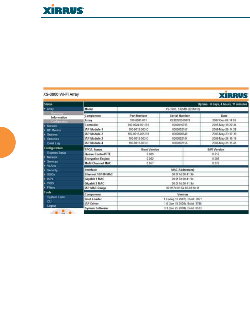
Array Information
This is a status only window that shows you the current firmware versions
utilized by the Array, the serial numbers assigned to each module, and MAC
addresses.
You cannot make configuration changes in this window, but if you are
experiencing issues with network services, you may want to print the content of
this window for your records.
Figure 68. Array Information
Array Configuration
This is a status only window that allows you to display the configuration settings
assigned to the Array, based on the following filter options:
zRunning—displays the current configuration (the one running now).
zSaved—displays the saved configuration from this session.
zLastboot—displays the configuration as it was after the last reboot.
Wi-Fi Array
Viewing Status on the Wi-Fi Array 133
zFactory—displays the configuration established at the factory.
Figure 69. Show Configuration
If you want to see just the differences between the Running, Saved, Lastboot, and
Factory configurations, you can do this by choosing a configuration option from
the Select Config pull-down menu then selecting an alternative configuration
option from the Select Diff pull-down menu.
You also have the option of including the default configuration settings in the
output. To do this, choose your configuration then click in the Include Defaults
check box. If Include Defaults is disabled, then only the changes from the default
configuration are shown.
Wi-Fi Array
134 Viewing Status on the Wi-Fi Array
Admin History
It is useful to know who else is currently logged in to an array while you're
configuring it. It's also nice to see who has logged in since the array booted. This
status-only window shows you all administrator logins to the Array that have
occurred since the last reboot. To determine who is currently logged in, check
which entries say active in the Logout Time column.
Figure 70. Admin Login History
Network Status Windows
The following Network Status windows are available:
zNetwork Map—displays information about this Array and neighboring
Arrays that have been detected.
zSpanning Tree Status—displays the spanning tree status of network
links on this Array.
zRouting Table—displays information about routing on this Array.
zARP Table—displays information about Address Resolution Protocol on
this Array.
zDHCP Leases—displays information about IP addresses (leases) that the
Array has allocated to client stations.
zConnection Tracking/NAT—lists connections that have been established
for client stations.
zCDP Neighbors—lists neighboring network devices using Cisco
Discovery Protocol.
Wi-Fi Array
Viewing Status on the Wi-Fi Array 135
Network Map
This window offers detailed information about this Array and all neighboring
Arrays, including how the Arrays have been set up within your network.
Figure 71. Network Map
You may sort the rows based on any column that has an active column header,
indicated when the mouse pointer changes to the hand icon . Click Refresh to
update the information at any time. Click Auto Refresh to instruct the Array to
refresh this window automatically.
Content of the Network Map Window
The network map includes the following status information for each Array:
zArray Name: The host name assigned to the Array. To establish the host
name, go to “Express Setup” on page 174.
zLocation: The location assigned to the Array. To establish the location
information, go to “Express Setup” on page 174.
zArray OS: The software version running on the Array.
zIP Address: The Array’s IP address. If DHCP is enabled, the Array’s IP
address is assigned by the DHCP server. If DHCP is disabled, you must
assign a static IP address. To enable DHCP or to assign a static IP address
for the Array, go to “Express Setup” on page 174.
Refresh

Wi-Fi Array
136 Viewing Status on the Wi-Fi Array
zIAPs Total: The number of IAPs on the Array.
zIAPs Up: Informs you how many IAPs are currently up and running. To
enable or disable all IAPs, go to “Express Setup” on page 174. To enable
or disable individual IAPs, go to “IAP Settings” on page 254.
zSSIDs: Informs you how many SSIDs have been assigned for the Array.
To assign an SSID, go to “SSID Management” on page 238.
zActive SSIDs: Informs you how many SSIDs are enabled. To enable or
disable SSIDs, go to “SSID Management” on page 238.
zStations: Informs you how many stations are associated to the Array. To
associate (or disassociate) a station, go to “Stations” on page 150.
zIn Range: Informs you whether the Array is within wireless range of
another Wi-Fi Array.
zFast Roam: Informs you whether or not the Xirrus fast roaming feature is
enabled. This feature utilizes the Xirrus Roaming Protocol (XRP) ensuring
fast and seamless roaming capabilities between IAPs or Arrays at both
Layer 2 and Layer 3. To enable or disable fast roaming, go to “Global
Settings (IAP)” on page 259.
zUptime (D:H:M): Informs you how long the Array has been up and
running (in Days, Hours and Minutes).
Spanning Tree Status
Multiple active paths between stations can cause loops in the network. If a loop
exists in the network topology, the potential exists for the duplication of
messages. The spanning tree protocol is a link management protocol that
provides path redundancy while preventing undesirable loops. For a wireless
network to function properly, only one active path can exist between two stations.
To facilitate path redundancy, the spanning tree protocol defines a tree that spans
all stations in the network and forces certain redundant data paths into a standby
(blocked) state. If one segment in the spanning tree becomes unreachable, the
spanning tree algorithm reconfigures the network topology and reestablishes the
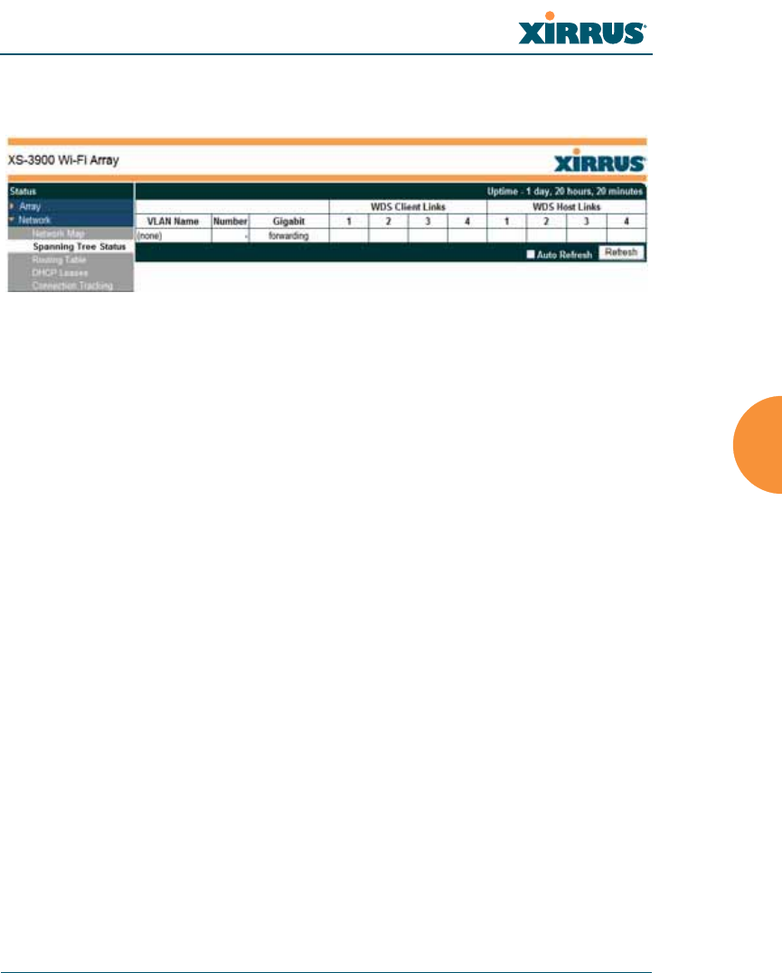
Wi-Fi Array
Viewing Status on the Wi-Fi Array 137
link by activating the standby path. The spanning tree function is transparent to
client stations.
Figure 72. Spanning Tree Status
This window shows the spanning tree status (forwarding or blocked) for path
segments that terminate on this Array. You may sort the rows based on the VLAN
Name or Number columns by clicking the column header. Click Refresh to
update the information at any time. Click Auto Refresh to instruct the Array to
refresh this window automatically.
See Also
DNS Settings
Network
Network Interfaces
Network Statistics
Network Status Windows
Wi-Fi Array
138 Viewing Status on the Wi-Fi Array
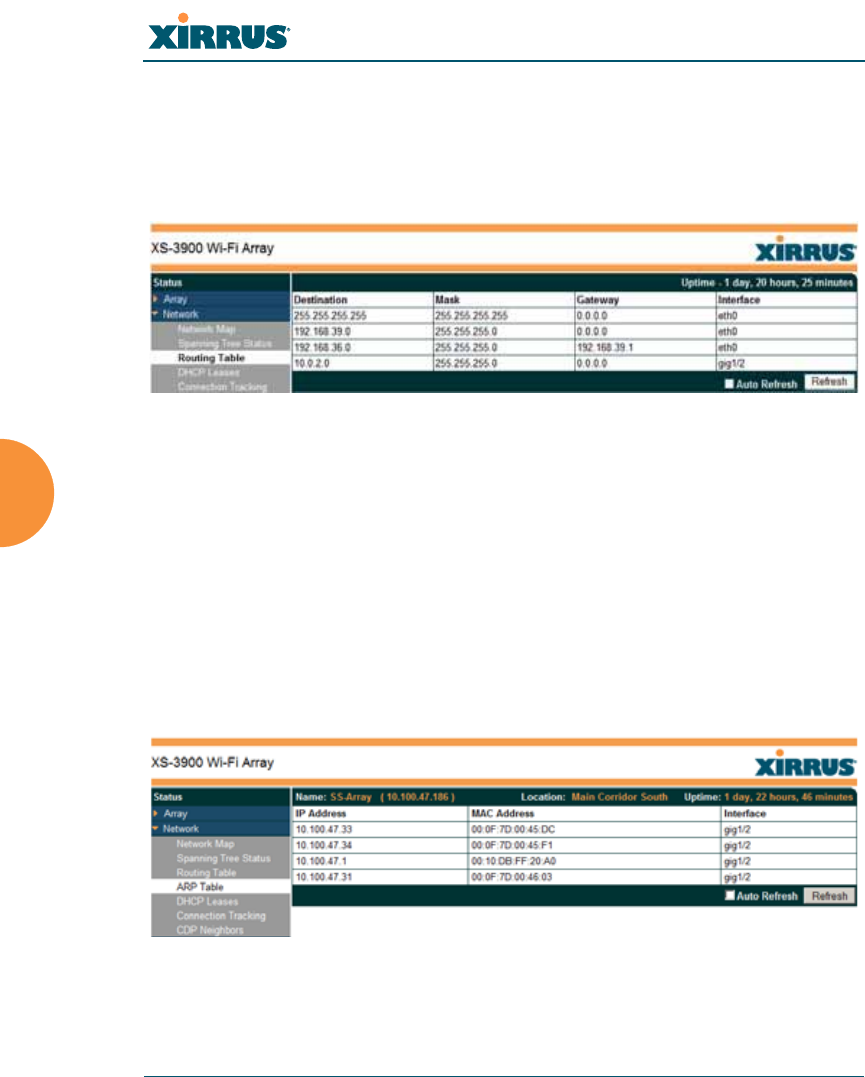
Routing Table
This status-only window lists the entries in the Array’s routing table. The table
provides the Array with instructions for sending each packet to its next hop on its
route across the network.
Figure 73. Routing Table
See Also
VLANs
Configuring VLANs on an Open SSID
ARP Table
This status-only window lists the entries in the Array’s ARP table. For a device
with a given IP address, this table lists the device’s MAC address. It also shows
the Array interface through which this device may be reached. The table typically
includes devices that are on the same local area network segment as the Array.
Figure 74. ARP Table
Wi-Fi Array
Viewing Status on the Wi-Fi Array 139
See Also
Routing Table
ARP Filtering
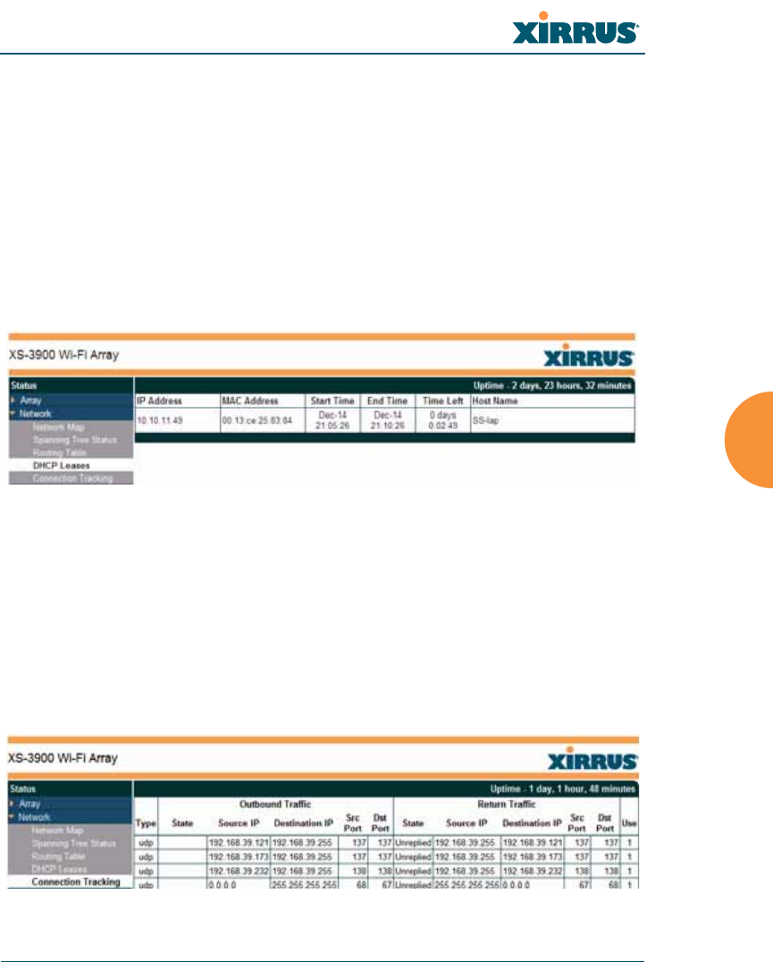
DHCP Leases
This status-only window lists the IP addresses (leases) that the Array has
allocated to client stations. For each, it shows the IP address assigned from one of
the defined DHCP pools, and the MAC address and host name of the client
station. The start and end time of the lease show how long the allocation is valid.
The same IP address is normally renewed at the expiration of the current lease.
Figure 75. DHCP Leases
See Also
DHCP Server
Connection Tracking/NAT
This status-only window lists the session connections that have been created on
behalf of clients. This table may also be used to view information about current
NAT sessions.
Figure 76. Connection Tracking
Wi-Fi Array
140 Viewing Status on the Wi-Fi Array
You may sort the rows based on any column that has an active column header,
indicated when the mouse pointer changes to the hand icon . Click Refresh to
update the information at any time. Click Auto Refresh to instruct the Array to
refresh this window automatically.
See Also
Filters
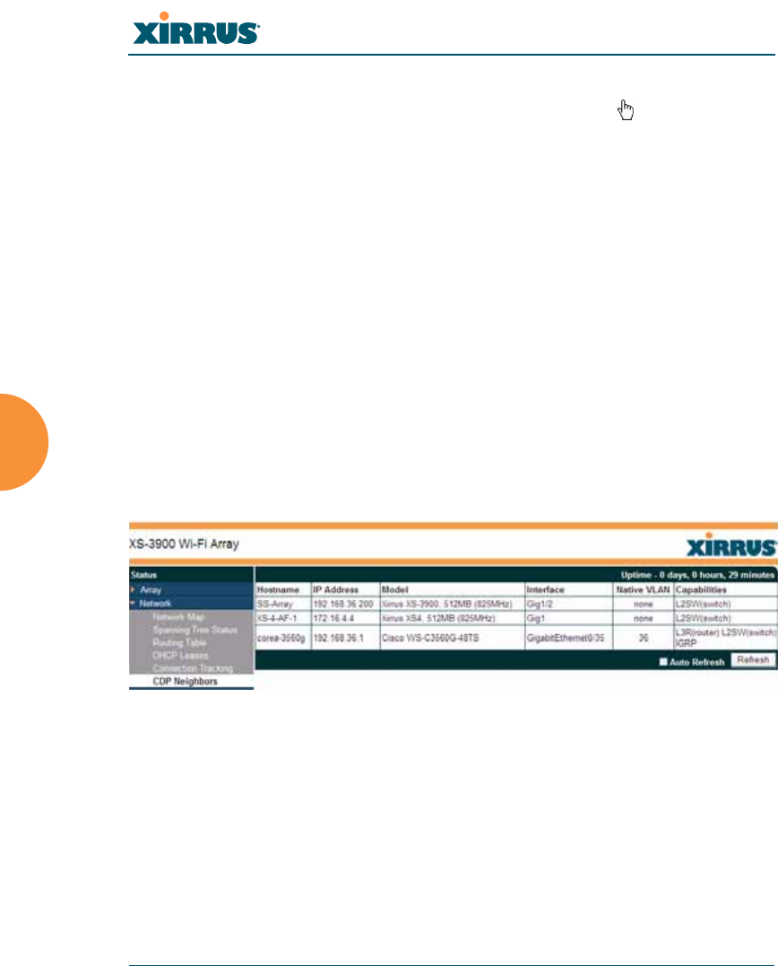
CDP Neighbors
This status-only window lists devices on the Array’s network that support the
Cisco Discovery Protocol (CDP). The Array performs discovery on the network
on an ongoing basis. This list shows the devices that have been discovered—Cisco
devices and other devices on the network that have CDP running. For each, it
shows the device’s host name, IP address, manufacturer and model name, the
device interface that is connected to the network (i.e., the port that was
discovered), and the network capabilities of the device (switch, router, supported
protocols, etc.).
Figure 77. CDP Neighbors
CDP must be enabled on the Array in order to gather and display this
information. See “CDP Settings” on page 189.

Wi-Fi Array
Viewing Status on the Wi-Fi Array 141
RF Monitor Windows
Every Wi-Fi Array includes an integrated RF spectrum analyzer as a standard
feature. The spectrum analyzer allows you to characterize the RF environment by
monitoring throughput, signal, noise, errors, and interference levels continually
per channel. This capability uses the built-in threat-sensor radio abg(n)2. The
associated software is part of the ArrayOS.
The following RF Status windows are available:
zIAPs—displays current statistics and RF measurements for each of the
Array’s IAPs.
zSpectrum Analyzer—displays current statistics and RF measurements
for each of the Array’s channels.
zIntrusion Detection—displays rogue APs that have been detected by the
Array.
Wi-Fi Array
142 Viewing Status on the Wi-Fi Array
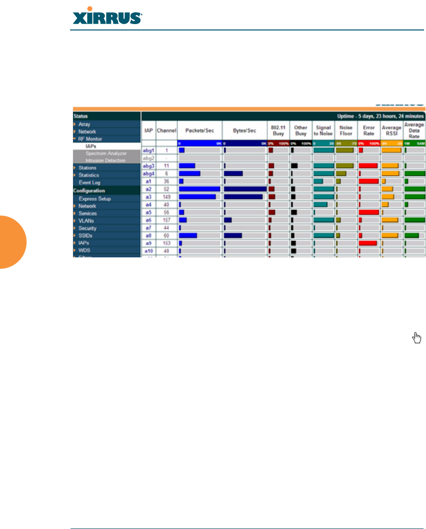
IAPs
The RF Monitor—IAPs window displays traffic statistics and RF readings
observed by each Array IAP (radio). Note that the data is an instantaneous
snapshot for the IAP—it is not an average or a cumulative total.
Figure 78. RF Monitor—IAPs
Figure 78 presents the data as a graphical display, enabled by selecting the Graph
checkbox on the lower left. If this option is not selected, data is presented as a
numerical table. You may sort the rows based on any column that has an active
column header, indicated when the mouse pointer changes to the hand icon .
Click Refresh to update the information at any time. Click Auto Refresh to
instruct the Array to refresh this window automatically.

Wi-Fi Array
Viewing Status on the Wi-Fi Array 143
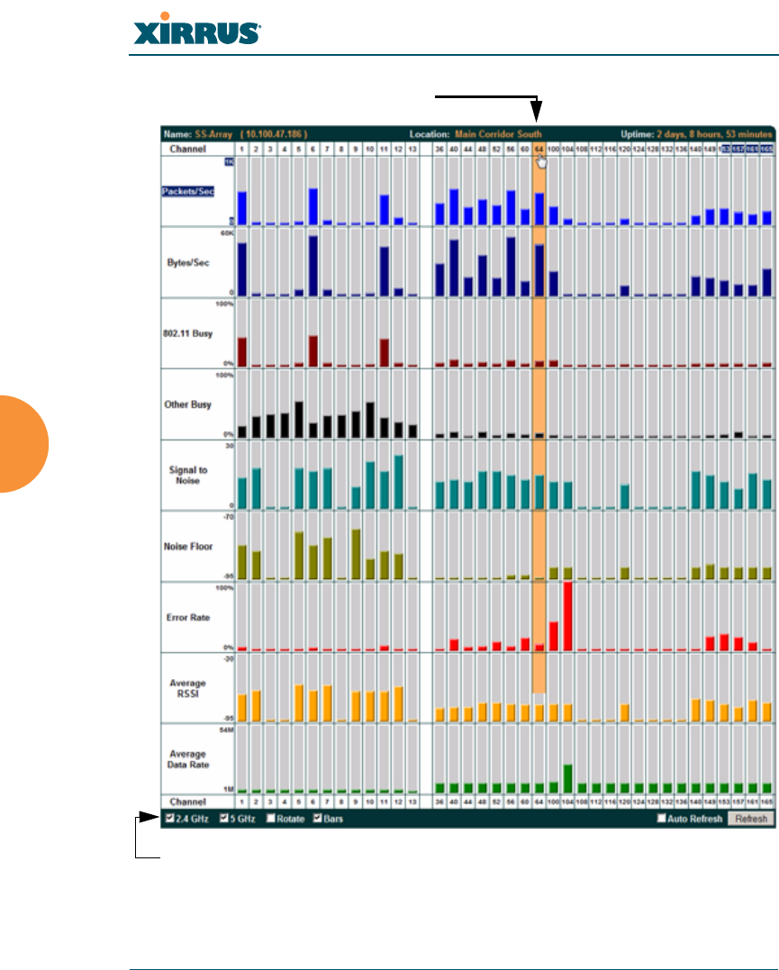
Spectrum Analyzer
Spectrum analysis on Wi-Fi Arrays is a distributed capability that automatically
covers the entire Wi-Fi network, since a sensor is present in every unit. Arrays
monitor the network 24/7 and analyze interference anywhere in the network
from your desk. There’s no need to walk around with a device as with traditional
spectrum analyzers, thus you don’t have to be in the right place to find outside
sources that may cause network problems or pose a security threat. The Array
monitors all 802.11 radio bands (a/b/g/n), not just those currently used for data
transmission.
The RF Spectrum Analyzer window displays instantaneous traffic statistics and
RF readings for all channels, as measured by the Array’s abg(n)2 radio. This
differs from the RF Monitor-IAPs window, which displays values measured by
each IAP radio for its current assigned channel. For the spectrum analyzer, the
abg(n)2 radio is in a listen-only mode, scanning across all Wi-Fi channels. Each
channel is scanned in sequence, for a 250 millisecond interval per channel. The
spectrum analyzer window presents the data as a graphical display of vertical bar
graphs for each statistic as shown in Figure 79 (the default presentation), or
horizontally as bar graphs or numerical RF measurements. The measurements
displayed are explained in “Spectrum Analyzer Measurements” on page 145.
As an aid to viewing data for a particular channel, click the channel number. The
channel will be highlighted down the page (or across the page for a rotated view,
in both text and graph modes). Click additional channels to highlight them for
easy comparison. To remove the highlighting from a channel, click the channel
number again. Click Refresh to update the information at any time. Click Auto
Refresh to instruct the Array to refresh this window automatically.
#The RF measurements for this feature are obtained by IAP abg(n)2, which
must be set to monitor mode for any data to be available. See “IAP
Settings” on page 254.
Wi-Fi Array
144 Viewing Status on the Wi-Fi Array
Figure 79. RF Spectrum Analyzer
Click Channel number to highlight
Select Display Options

Wi-Fi Array
Viewing Status on the Wi-Fi Array 145
The Spectrum Analyzers offers several display options:
zTo display horizontal bar graphs, click the Rotate checkbox at the bottom
of the data window.
zIn the rotated view, if you wish to view data as a numerical table, click the
Text checkbox. Click again to return to a graphical display. The text
option is only available in the rotated view.
zWhen viewing a graphical display, click Bars to have the bar graphs
displayed against a gray background—you may find this easier on the
eyes. This operation is not available when Text is selected.
zYou may sort the rows based on any column that has an active column
header, indicated when the mouse pointer changes to the hand icon .
Sorting is only available in the rotated view.
zAt the bottom left of the frame, you may select whether to display only
2.4 GHz channels, 5 GHz channels, or both (both is the default). Note that
the data is an instantaneous snapshot—it is not an average or a
cumulative total.
Spectrum Analyzer Measurements
The spectrum analyzer displays the following information:
zPackets/Sec: Total number of Wi-Fi packets per second on the channel,
both valid and errored packets.
zBytes/Sec: Total number of Wi-Fi bytes per second on the channel, valid
packets only.
z802.11 Busy: Percentage of time that 802.11 activity is seen on the channel.
zOther Busy: Percentage of time that the channel is unavailable due to
non-802.11 activity.
The total busy time (802.11 Busy plus Other Busy) will never total more
than 100%. The remaining time (100% minus total busy time) is quiet
time—the time that no activity was seen on the channel.

Wi-Fi Array
146 Viewing Status on the Wi-Fi Array
zSignal to Noise: Average SNR (signal to noise ratio) seen on the channel,
calculated from the signal seen on valid 802.11 packets less the noise floor
level. A dash value “-“ means no SNR data was available for the interval.
zNoise Floor: Average noise floor reading seen on the channel (ambient
noise). A dash value “-“ means no noise data was available for the
interval.
zError Rate: Percentage of the total number of Wi-Fi packets seen on the
channel that have CRC errors. The Error rate percentage may be high on
some channels since the monitor radio is set to receive at a very sensitive
level, enabling it to hear packets from devices at far distances.
zAverage RSSI: Average RSSI level seen on 802.11 packets received on the
channel. A dash value “-“ means no RSSI data was available for the
interval.
zAverage Data Rate: Average data rate over time (per byte, not per packet)
seen on 802.11 packets received on the channel. A dash value “-“ means
no data rate information was available for the interval. A higher date rate
(above 6 Mbps) typically indicates user data traffic on the channel.
Otherwise, the data rate reflects control packets at the lower basic rates.
Wi-Fi Array
Viewing Status on the Wi-Fi Array 147
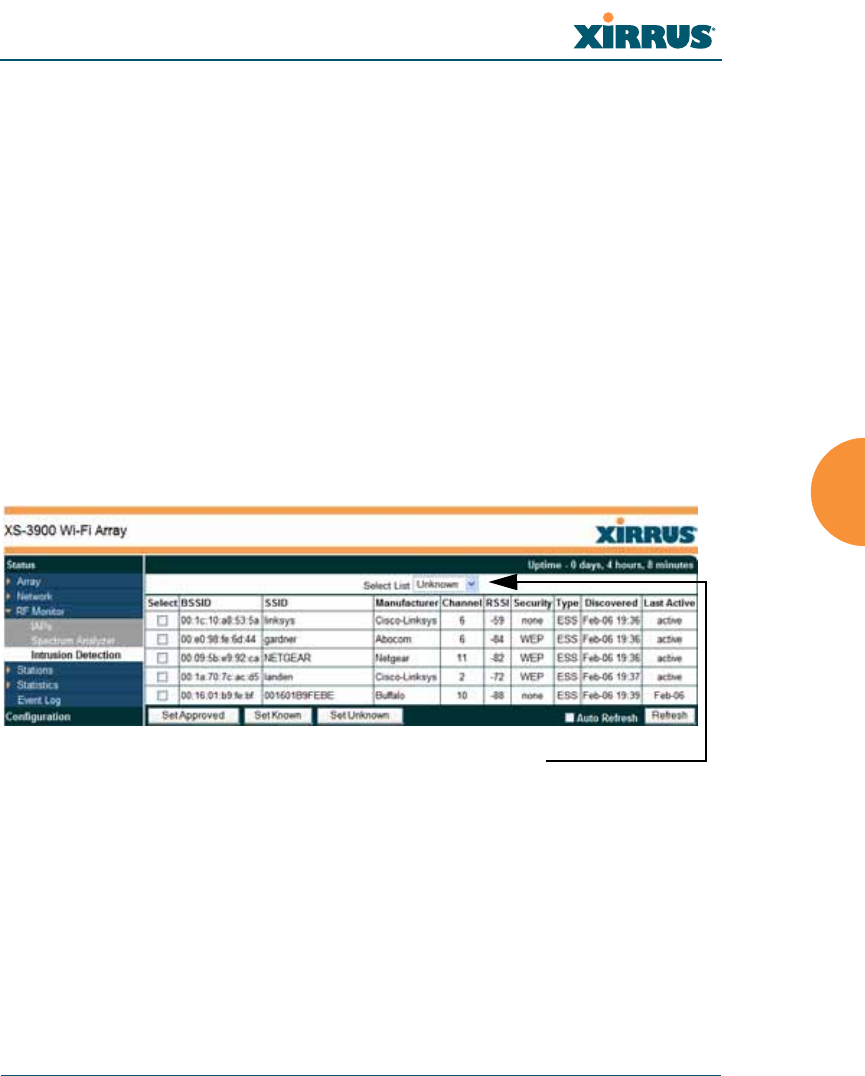
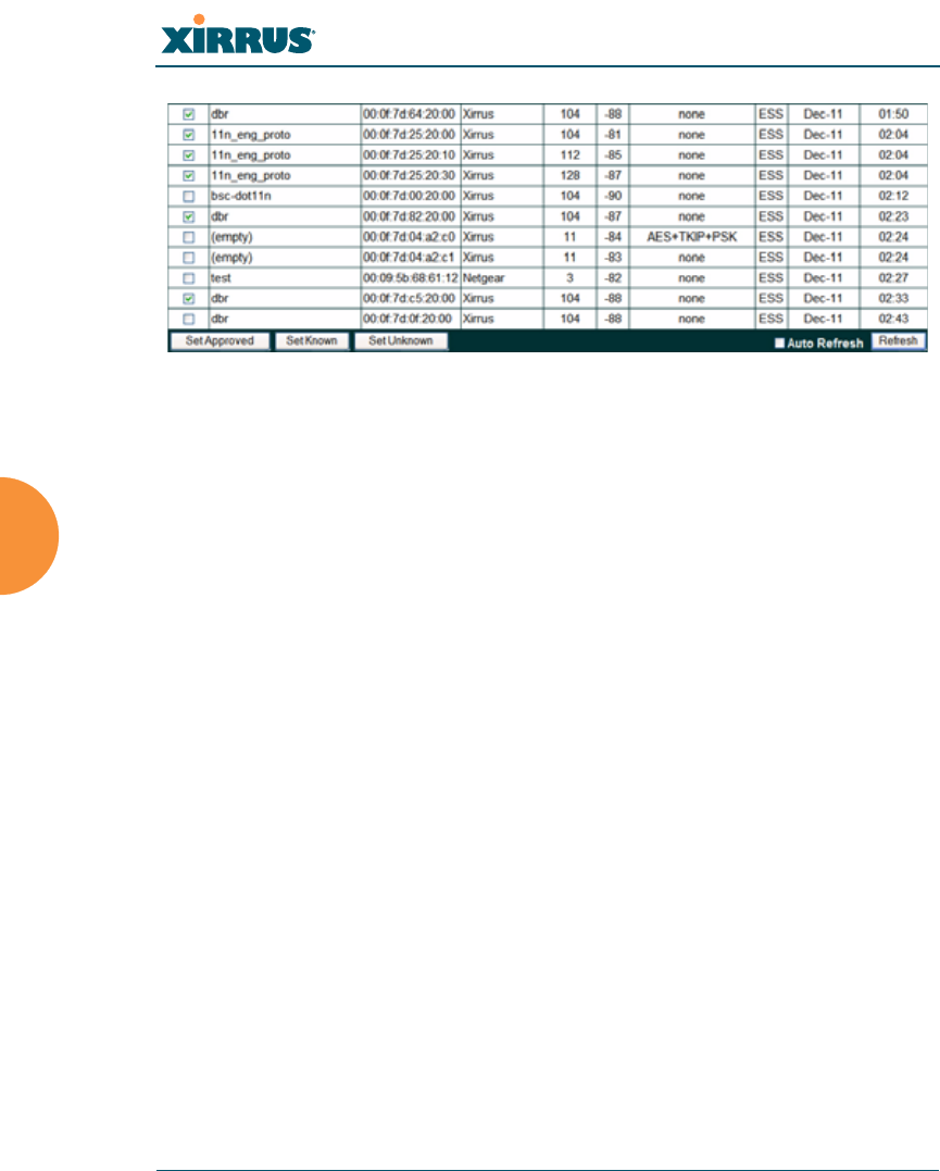
Intrusion Detection
This window displays all detected access points, according to the category you
select from the drop-down list at the top—either Unknown, Known or Approved.
This includes ad hoc access points (station-to-station connections). You can sort
the results based on the following parameters by clicking the desired column
header:
Figure 80. Intrusion Detection/Rogue AP List
The Intrusion Detection window provides the easiest method for designating
rogue APs as Known. Approved, or Unknown. Choose one or more APs using the
checkbox in the Select column, then set whether they are Approved, Known, or
Unknown using the buttons on the lower left. (Figure 81)
zSSID zSecurity
zBSSID zType
zManufacturer zDiscovered
zChannel zLast Active
zRSSI
Select the type of AP to display
Wi-Fi Array
148 Viewing Status on the Wi-Fi Array
Figure 81. Categorizing APs
You can refresh the list at any time by clicking on the Refresh button, or click in
the Auto Refresh check box to instruct the Array to refresh the list automatically.
See Also
Network Map
Rogue Control List
SSIDs
SSID Management

Wi-Fi Array
Viewing Status on the Wi-Fi Array 149
Station Status Windows
The following Station Status windows are available:
zStations—this list describes all stations associated to the Array.
zLocation Map—displays a map showing the approximate locations of all
stations associated to the array.
zRSSI—for each associated station, this displays the Received Signal
Strength Indicator at each of the Array’s IAPs.
zSignal-to-Noise Ratio (SNR)—for each associated station, this displays
the SNR at each of the Array’s IAPs.
zNoise Floor—for each associated station, this displays the ambient noise
(silence) value at each of the Array’s IAPs.
zMax by IAP—for each IAP, this shows the historical maximum number of
stations that have been associated to it over various periods of time.
Wi-Fi Array
150 Viewing Status on the Wi-Fi Array
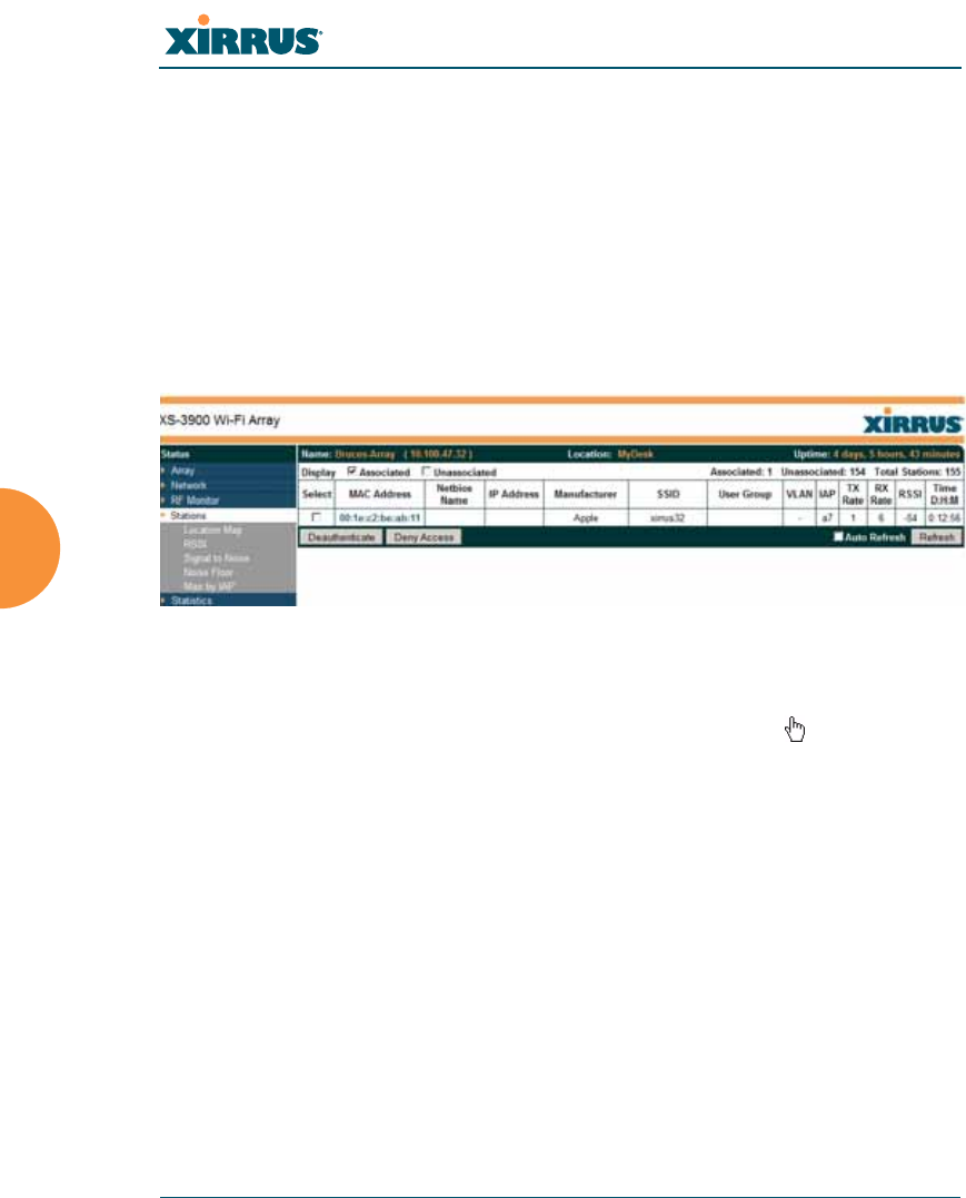
Stations
This status-only window shows client stations currently visible to the Array. You
may choose to view only stations that have associated to the Array, or only
stations that are not associated, or both, by selecting the appropriate checkboxes
above the list. The list shows the MAC address of each station, its NetBIOS name,
its IP address, its manufacturer, the SSID used for the association, the Group (if
any) that this station belongs to, its VLAN, the IAP used for the association,
transmit and receive rates, the RSSI for each station, and how long each
association has been active (up time).
Figure 82. Stations
You may sort the rows based on any column that has an active column header,
indicated when the mouse pointer changes to the hand icon . Click again to
reverse the sort order. You may select a specific station and perform one of the
following actions by clicking the associated button:
zDeny Access: Sends a de-authentication frame to the selected station and
explicitly denies it access by adding its MAC address to the Deny List in
the Access Control List window. To permit access again, go to “Access
Control List” on page 221 and delete the station from the Deny list.
zDeauthenticate: Sends a de-authentication frame to the selected station.
The station may re-authenticate.
Click on the Refresh button to refresh the station list, or click in the Auto Refresh
check box to instruct the Array to refresh this window automatically.
Wi-Fi Array
Viewing Status on the Wi-Fi Array 151
See Also
Access Control List
Station Status Windows
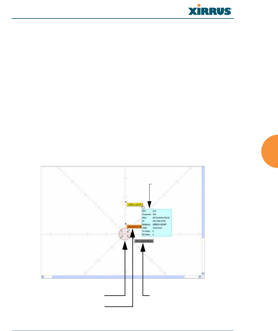
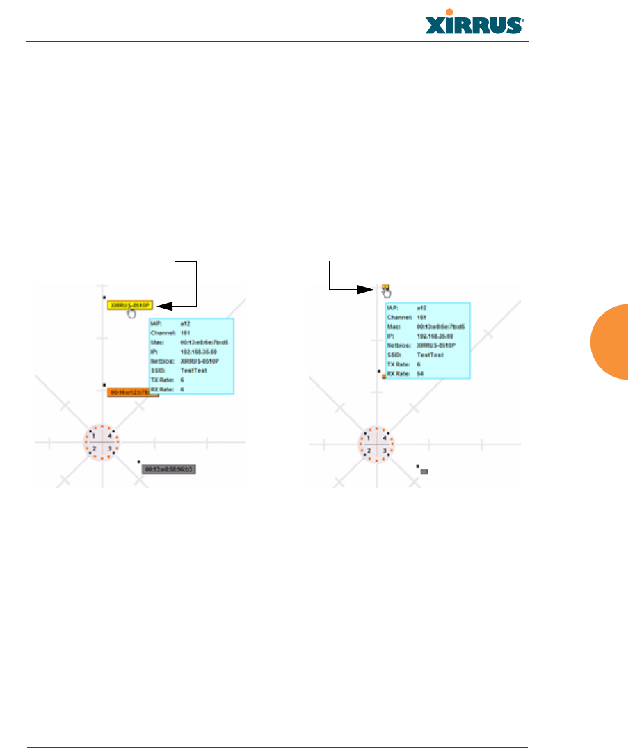
Location Map
The Location Map shows the approximate locations of stations relative to this
Array. You may display stations associated to this Array, unassociated stations
(shown in gray), or both. The station count is shown on the left, above the map.
You may also choose to display 5 GHz stations (shown in orange) or 2.4 GHz
stations (shown in green), or both.
The map and Array are shown as if you were looking down on the Array from
above, say from a skylight on the roof. Thus the positions of the radios abg(n)1 to
abg(n)4 are a mirror image of the way they are typically drawn when looking at
the face of the Array. Radios abg(n)1 to abg(n)4 are marked (1 to 4) on the map to
show the orientation of the Array.
Figure 83. Location Map
Array
Associated Station
Unassociated Station
Hover mouse to
show details

Wi-Fi Array
152 Viewing Status on the Wi-Fi Array
A station is identified by its NetBIOS name if known, or else by its IP or MAC
address. Hover the mouse over a station to show detailed information. If multiple
stations are near each other, they will be displayed slightly offset so that one
station does not completely obscure another. You may minimize a station that is
not of interest by clicking it. Click it again for normal display. There is also a
Minimize All button.
You may replace the range-finder background image above with your own
custom image of the floorplan of the area served by the Array.
Controls and items displayed on the Location Map window
Figure 84. Controls for Location Map
#The controls for the Location Map are all at the bottom of the window and
take up a fair amount of width. If some of the controls shown in Figure 84 are
not visible, resize your browser window to be wider until all of the controls
appear.
Also, the Location Map has its own scroll bars in addition to the browser’s
scroll bars. If you narrow the browser window, the map’s scroll bar may be
hidden. Use the browser’s bottom scroll bar if you need to move it into view.
Stations to display Scale
Replace background
Minimize stations
Reset display Rotate map
Zoom in
Zoom out
Wi-Fi Array
Viewing Status on the Wi-Fi Array 153
zDisplay Associated/Unassociated: Select whether to display stations that
are associated to the Array, stations that are not associated, or both.
zDisplay 2.4 GHz/5 GHz: Select whether to display 802.11bg(n) stations,
or 802.11a(n) stations, or both.
zMinimize All: All stations are shown by default with their NetBIOS
name or IP or MAC address. If the map is too cluttered, you can reduce
the display for each station to a small rectangle. You may still display
detailed information for the station by hovering over it. To enlarge all
rectangles, clear the Minimize All checkbox.
Figure 85. Minimizing stations
zScale: This view-only value shows the approximate distance represented
by each hashmark on the default map background. Scale is the rightmost
of the items displayed in the control area - you may need to scroll to the
right edge to see it.
zCustom Image: Use this feature to replace the default background image
with your own image of the floor plan of your location. Click the Browse
button and browse to the desired file on your computer. This may be a
.gif, .jpg, .jpeg., .png, .htm, or .html file. The scale of the file should be 100
feet per inch. Then click Upload (see below). For more information on
Normal station display Minimized station display
Wi-Fi Array
154 Viewing Status on the Wi-Fi Array
using the custom, image, see “Working with the Custom Image” on
page 154.
zUpload: After browsing to the desired custom image, click the Upload
button to install it. The map will be redisplayed with your new
background. No hash marks are added to the image display.
zReset: Click this button to restore the map display to the factory settings.
All attributes are restored—including the stations selected for display, the
scale, the rotation, and the background map.
zRotate: Click this button to rotate the orientation of the entire map. It
rotates the map 45o counter-clockwise.
zEnlarge: Click this button to enlarge (zoom in on) the map. The displayed
Scale on the bottom right is updated with the new scale for the map.
zReduce: Click this button to reduce (zoom out on) the map.
The displayed Scale on the bottom right is updated with the new scale for
the map
zAuto Refresh: Instructs the Array to refresh this window automatically.
zRefresh: Updates the stations displayed.
See Also
Access Control List
Station Status Windows
Working with the Custom Image
After you have uploaded a custom image (see Custom Image and Upload in
“Controls and items displayed on the Location Map window” on page 152), you
should move the display of the Array on your map to correspond with its actual
location at your site. The Location Map window provides a special set of controls
for moving the location of the Array. These controls are displayed on the upper
right corner of the map (Figure 86). The location controls only appear when you
are using a custom image for your background. You will not see them if you are
using the default map background.
To move the Array on the map in a particular direction, click an arrow for the
desired direction on the location controls. The inner arrows move the Array by
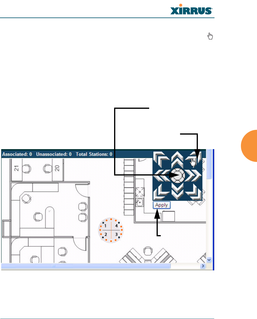
Wi-Fi Array
Viewing Status on the Wi-Fi Array 155
small steps; the outer arrows move it by larger steps. The arrows only work when
you position the mouse directly over them—make sure you see the hand icon .
If you need to return the Array to the center of the map, click the center of the
location controls. When you are done, click the Apply button to save the new
Array location, as well as the enlarge/reduce/rotate settings. These location
settings will persist for the duration of the current WMI session, but not after a
reboot (but the custom image will still be used after rebooting—whether or not
you click Apply).
Figure 86. Setting Array location on a Custom Image
Click an arrow to move
the Array
Array Location Controls
are at upper left of Map
Click here to move
Array to center of map
Apply Button
Wi-Fi Array
156 Viewing Status on the Wi-Fi Array
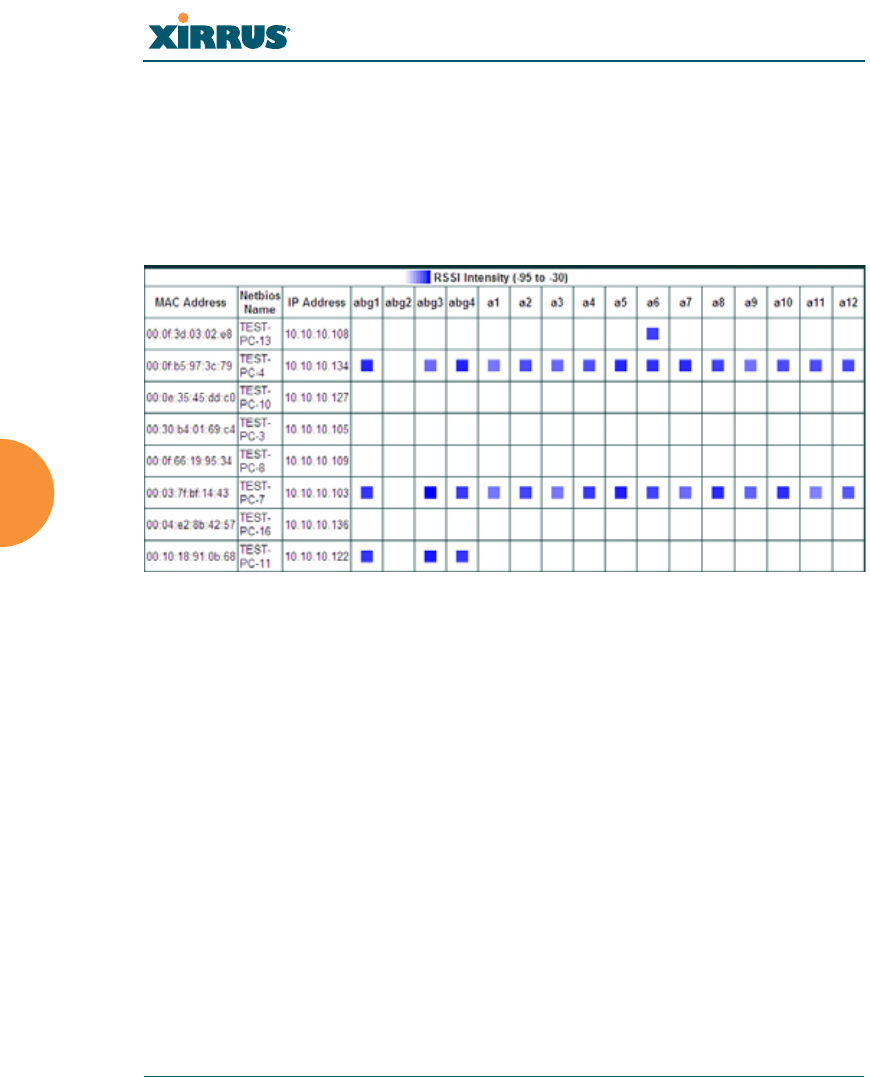
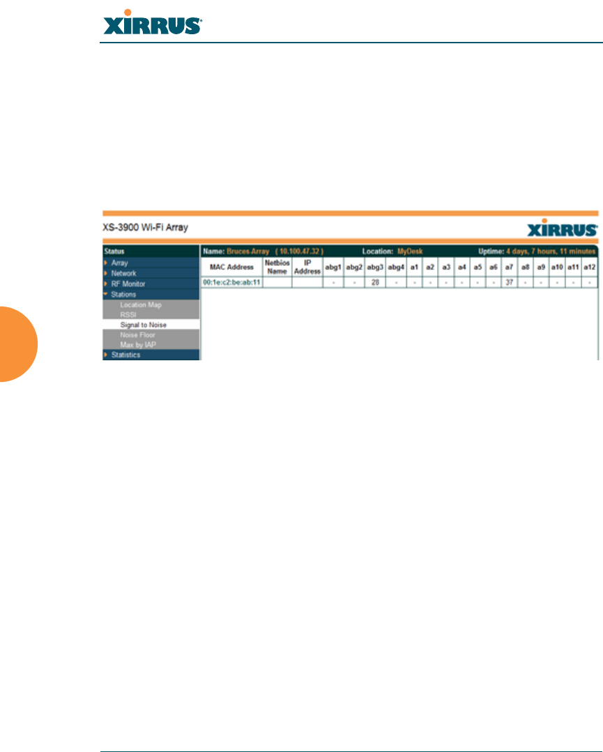
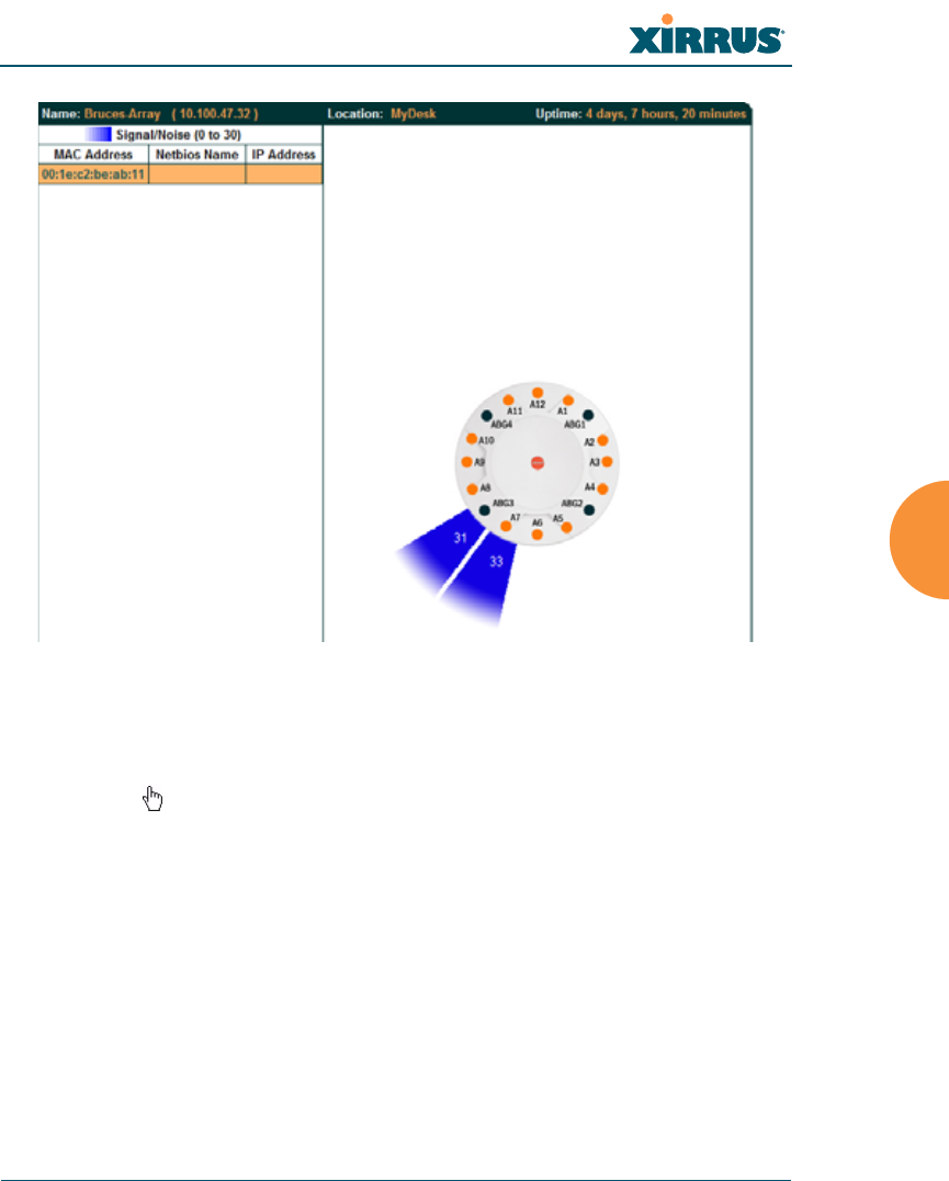
RSSI
For each station that is associated to the Array, the RSSI (Received Signal Strength
Indicator) window shows the station’s RSSI value as measured by each IAP. In
other words, the window shows the strength of the station’s signal at each radio.
You may choose to display Unassociated Stations as well with a checkbox at the
bottom of the window.
Figure 87. Station RSSI Values
By default, the RSSI is displayed numerically. You may display the relative
strength using color if you select Colorize Intensity, with the strongest signals
indicated by the most intense color. (Figure 87) If you select Graph, then the RSSI
is shown on a representation of the Array, either colorized or numerically based
on your selection. (Figure 88) The stations are listed to the left of the Array—click
on a station to show its RSSI values on the Array.
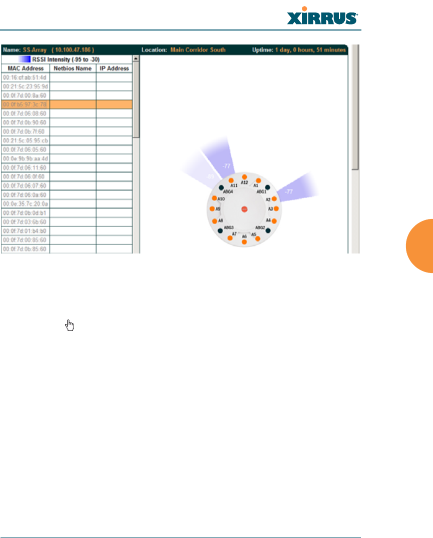
Wi-Fi Array
Viewing Status on the Wi-Fi Array 157
Figure 88. Station RSSI Values—Colorized Graphical View
In either graphical or tabular view, you may sort the rows based on any column
that has an active column header, indicated when the mouse pointer changes to
the hand icon . Click on the Refresh button to refresh the station list, or click in
the Auto Refresh check box to instruct the Array to refresh this window
automatically.
See Also
Station Status Windows
RF Monitor Windows
Wi-Fi Array
158 Viewing Status on the Wi-Fi Array
Signal-to-Noise Ratio (SNR)
For each station that is associated to the Array, the Signal-to-Noise Ratio (SNR)
window shows the station’s SNR value as measured by each IAP. In other words,
the window shows the SNR of the station’s signal at each IAP radio. The signal-
to-noise ratio can be very useful for determining the cause of poor performance at
a station. A low value means that action may need to be taken to reduce sources of
noise in the environment and/or improve the signal from the station.
Figure 89. Station Signal-to-Noise Ratio Values
You may choose to display Unassociated Stations as well with a checkbox at the
bottom of the window.
By default, the SNR is displayed numerically. (Figure 89) You may display
the relative value using color if you select Colorize Intensity, with the highest
SNR indicated by the most intense color. (Figure 90) If you select Graph, then
the SNR is shown on a representation of the Array, either colorized or numerically
based on your selection. The stations are listed to the left of the Array—click on a
station to show its SNR values on the Array.
Wi-Fi Array
Viewing Status on the Wi-Fi Array 159
Figure 90. Station SNR Values—Colorized Graphical View
In either graphical or tabular view, you may sort the rows based on any column
that has an active column header, indicated when the mouse pointer changes to
the hand icon . Click on the Refresh button to refresh the station list, or click in
the Auto Refresh check box to instruct the Array to refresh this window
automatically.
See Also
Station Status Windows
RF Monitor Windows
Wi-Fi Array
160 Viewing Status on the Wi-Fi Array
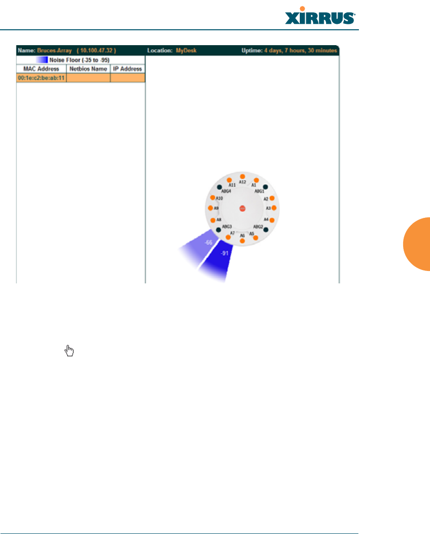
Noise Floor
For each station that is associated to the Array, the Noise Floor window shows
the ambient noise affecting a station’s signal as measured by each IAP. The noise
floor is the RSSI value when the station is not transmitting, sometimes called a
Silence value. In other words, the window shows the noise floor of the station’s
signal at each IAP radio. The noise floor value can be very useful for
characterizing the environment of a station to determine the cause of poor
performance. A relatively high value means that action may need to be taken to
reduce sources of noise in the environment.
Figure 91. Station Noise Floor Values
You may choose to display Unassociated Stations as well with a checkbox at the
bottom of the window.
By default, the noise floor is displayed numerically. (Figure 91) You may display
the relative value using color if you select Colorize Intensity, with the highest
noise indicated by the most intense color. If you select Graph, then the ambient
noise is shown on a representation of the Array, either colorized or numerically
based on your selection.(Figure 92) The stations are listed to the left of the
Array—click on a station to show its values on the Array.
Wi-Fi Array
Viewing Status on the Wi-Fi Array 161
Figure 92. Station Noise Floor Values—Colorized Graphical View
In either graphical or tabular view, you may sort the rows based on any column
that has an active column header, indicated when the mouse pointer changes to
the hand icon . Click on the Refresh button to refresh the station list, or click in
the Auto Refresh check box to instruct the Array to refresh this window
automatically.
See Also
Station Status Windows
RF Monitor Windows
Wi-Fi Array
162 Viewing Status on the Wi-Fi Array
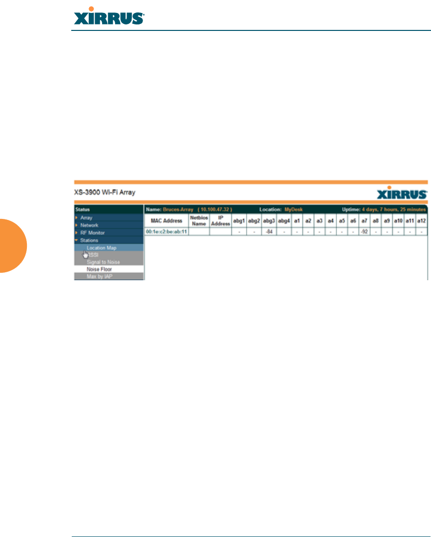
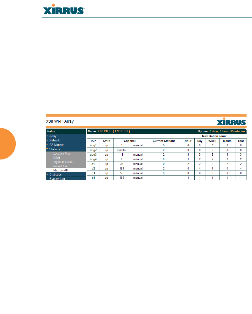
Max by IAP
This status-only window shows the maximum number of client stations that have
historically been associated to the Array. For each IAP, the list shows the IAP’s
state and channel number, the current number of stations associated, and the
highest number of stations that have been associated over various periods of time:
hour, day, week, month, and year. In other words, the Max Station Count shows
the “high water mark” over the selected period of time—the maximum count of
stations for the selected period, rather than a cumulative count of all stations that
have associated. This information aids in network administration and in planning
for additional capacity.
Figure 93. Max by IAP
You may click an IAP to go to the IAP Settings window. Click on the Refresh
button to refresh the station list, or click Auto Refresh to instruct the Array to
refresh this window automatically.
See Also
IAPs
Station Status Windows

Wi-Fi Array
Viewing Status on the Wi-Fi Array 163
Statistics Windows
The following Array Statistics windows are available:
zIAP Statistics Summary—provides an overview of the statistical data
associated with all IAPs. Expands to show links for displaying detailed
statistics for individual IAPs.
zPer-IAP Statistics—provides detailed statistics for an individual IAP.
zNetwork Statistics—displays statistical data associated with each
network (Ethernet) interface.
zVLAN Statistics—provides statistical data associated with your assigned
VLANs.
zWDS Statistics—provides statistical data for all WDS client and host
links.
zFilter Statistics—provides statistical data for all configured filters.
zStation Statistics—provides statistical data associated with each station.
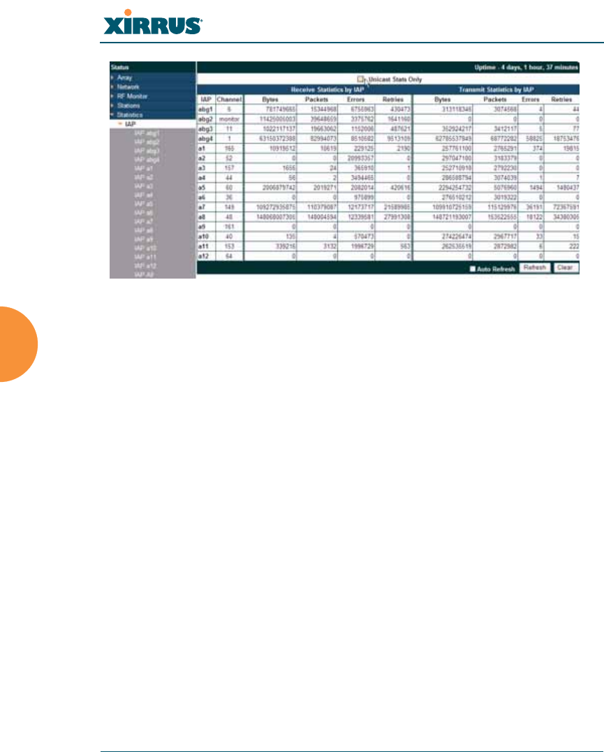
IAP Statistics Summary
This is a status only window that provides an overview of the statistical data
associated with all IAPs. It also shows the channel used by each IAP. For detailed
statistics for a specific IAP, see “Per-IAP Statistics” on page 164. Click the Unicast
Stats Only checkbox above the statistics to filter the results, or clear the checkbox
to show statistics for all wireless traffic.
You can Refresh the data (update the window with the latest information) or
Clear the data (reset all content to zero and begin counting again) at any time by
clicking on the appropriate button. You can also click in the Auto Refresh check
box to instruct the Array to refresh this window automatically.
Wi-Fi Array
164 Viewing Status on the Wi-Fi Array
Figure 94. IAP Statistics Summary Page
See Also
System Log Window
Global Settings (IAP)
Global Settings .11a
Global Settings .11bg
IAPs
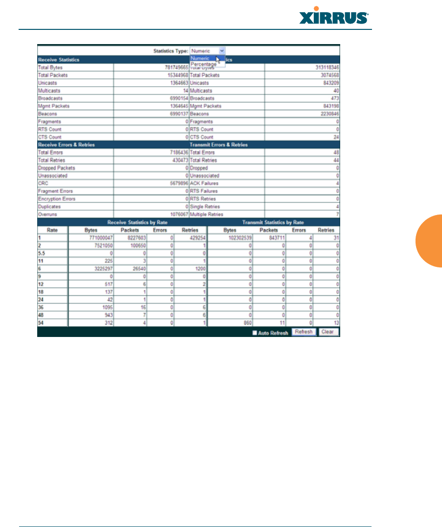
Per-IAP Statistics
This is a status only window that provides detailed statistics for the selected IAP.
If you click the link for IAP All in the left frame, each detailed statistic field will
show the sum of that statistic for all IAPs. For a summary of statistics for all IAPs,
see “IAP Statistics Summary” on page 163. Use the Statistics Type drop-down
field above the statistics to select the output format - Numeric for raw numbers,
or Percentage to express each statistic as a percentage of the total at the top of the
column.
A quick way to display the statistics for a particular IAP is by clicking the Array
graphic at the bottom left of the WMI window. Click the desired IAP, and the
selected statistics will be displayed. See “User Interface” on page 123.
Wi-Fi Array
Viewing Status on the Wi-Fi Array 165
Figure 95. Individual IAP Statistics Page (for IAP abg(n)1)
You can Refresh the data (update the window with the latest information) or
Clear the data (reset all content to zero and begin counting again) at any time by
clicking on the appropriate button. You can also click in the Auto Refresh check
box to instruct the Array to refresh this window automatically.
See Also
System Log Window
Global Settings (IAP)
Global Settings .11a
Global Settings .11bg
Wi-Fi Array
166 Viewing Status on the Wi-Fi Array
IAPs
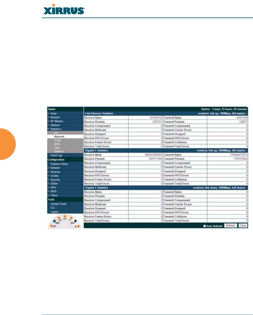
Network Statistics
This is a status only window that allows you to review statistical data associated
with each network (Ethernet) interface and its activity. You can Refresh the data
(update the window with the latest information) or Clear the data (reset all
content to zero and begin counting again) at any time by clicking on the
appropriate button. You can also click in the Auto Refresh check box to instruct
the Array to refresh this window automatically. If you are experiencing problems
on the Array, you may also want to print this window for your records.
Figure 96. Network Statistics
See Also
DHCP Server
DNS Settings
Network
Network Interfaces
Wi-Fi Array
Viewing Status on the Wi-Fi Array 167
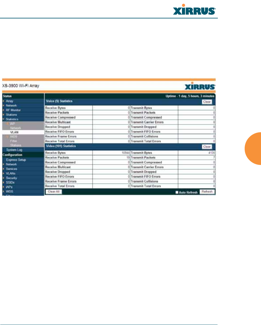
VLAN Statistics
This is a status only window that allows you to review statistical data associated
with your assigned VLANs. You can refresh the information that is displayed on
this page at any time by clicking on the Refresh button, or select the Auto Refresh
option for this window to refresh automatically. The Clear All button at the lower
left allows you to clear (zero out) all VLAN statistics.
Figure 97. VLAN Statistics
See Also
VLAN Management
VLANs
Wi-Fi Array
168 Viewing Status on the Wi-Fi Array
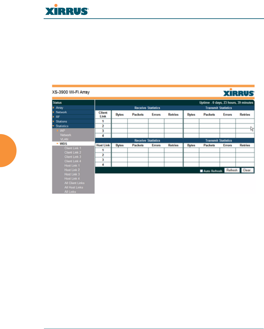
WDS Statistics
The main WDS Statistics window provides statistical data for all WDS client and
host links. To access data about a specific WDS client or host link, simply click on
the desired link in the left frame to access the appropriate window. You can also
select to view a sum of the statistics for all client links, all host links, or all links
(both client and host links).
Figure 98. WDS Statistics
See Also
SSID Management
WDS
Wi-Fi Array
Viewing Status on the Wi-Fi Array 169
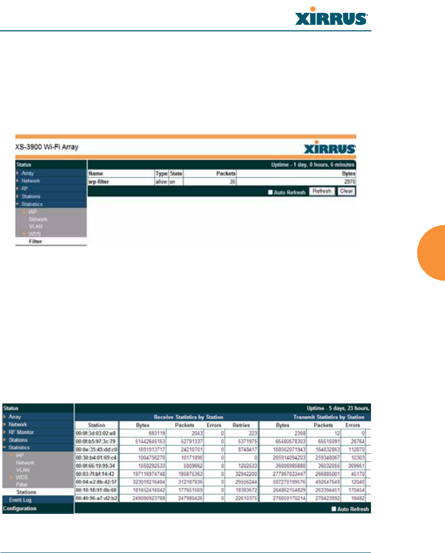
Filter Statistics
The Filter Statistics window provides statistical data for all configured filters. The
name, state (enabled—on or off), and type (allow or deny) of each filter is shown.
For enabled filters, this window shows the number of packets and bytes that met
the filter criteria. Click on a column header to sort the rows based on that column.
Click on a filter name to edit the filter settings.
Figure 99. Filter Statistics
See Also
Filters
Station Statistics
This status-only window provides an overview of statistical data for all stations.
Stations are listed by MAC address, and Receive and Transmit statistics are
summarized for each. For detailed statistics for a specific station, click the desired
MAC address in the Station column and see “Per-Station Statistics” on page 170.
Figure 100. Station Statistics
Wi-Fi Array
170 Viewing Status on the Wi-Fi Array
You can Refresh the data (update the window with the latest information) at any
time by clicking on the appropriate button. You can also click in the Auto Refresh
check box to instruct the Array to refresh this window automatically.
Note that you can clear the data for an individual station (see below), but you
cannot clear the data for all stations using this window.
See Also
Per-Station Statistics
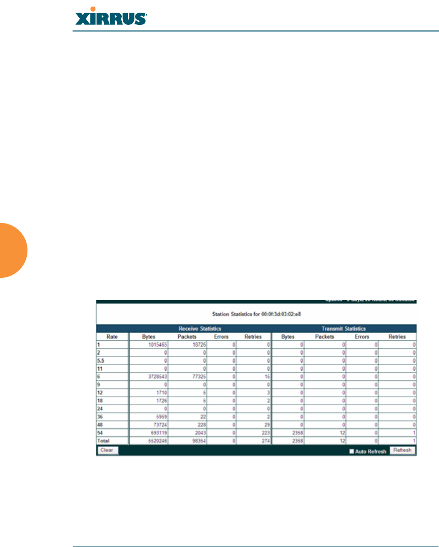
Per-Station Statistics
This window provides detailed statistics for the selected station. Receive and
Transmit statistics are listed by Rate—this is the data rate in Mbps. For a
summary of statistics for all stations, see “Station Statistics” on page 169.
You can Refresh the data (update the window with the latest information) or
Clear the data (reset all content to zero and begin counting again) at any time by
clicking on the appropriate button. You can also click in the Auto Refresh check
box to instruct the Array to refresh this window automatically.
Figure 101. Individual Station Statistics Page
See Also
Station Statistics
Wi-Fi Array
Viewing Status on the Wi-Fi Array 171
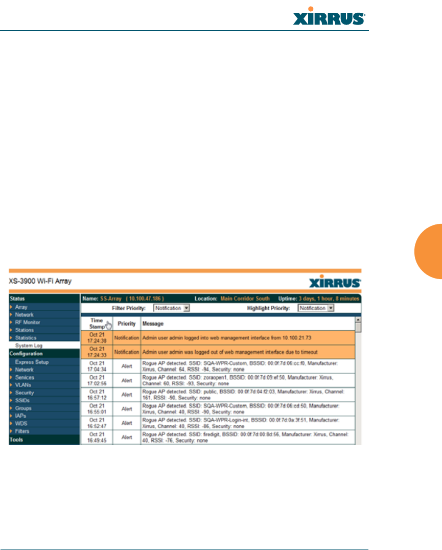
System Log Window
This is a status only window that allows you to review the system log, where
system alerts and messages are displayed. Although there are no configuration
options available in this window, you do have the usual choice of deciding how
the event messages are sorted by clicking in the column header for the desired
field (Time Stamp, Priority, or Message).
zTime Stamp—sorts the list based on the time the event occurred.
zPriority—sorts the list based on the priority assigned to the message.
zMessage—sorts the list based on the message category
The displayed messages may be filtered by using the Filter Priority option, which
allows control of the minimum priority level displayed. For example, you may
choose (under Services >System Log) to log messages at or above the Debug
level but use Filter Priority to display only messages at the Information level and
above.
Figure 102. System Log
Use the Highlight Priority field if you wish to highlight messages at the selected
priority level. Click on the Refresh button to refresh the message list, or click on
the Clear Log button to delete all messages. You can also click in the Auto
Refresh check box to instruct the Array to refresh this window automatically.

Wi-Fi Array
172 Viewing Status on the Wi-Fi Array

Wi-Fi Array
Configuring the Wi-Fi Array 173
Configuring the Wi-Fi Array
The following topics include procedures for configuring the Array using the
product’s embedded Web Management Interface (WMI). Procedures have been
organized into functional areas that reflect the flow and content of the WMI.
The following WMI windows allow you to establish configuration parameters for
your Array, and include:
z“Express Setup” on page 174
z“Network” on page 180
z“Services” on page 191
z“VLANs” on page 203
z“Security” on page 207
z“SSIDs” on page 233
z“Groups” on page 245
z“IAPs” on page 252
z“WDS” on page 285
z“Filters” on page 289
After making changes to the configuration settings of an Array you must click on
the Save button at the bottom of the configuration window, otherwise the changes
you make will not be applied the next time the Array is rebooted. Click the Apply
button if you want the changes applied to the current configuration, without
making them permanent.
This chapter only discusses using the configuration windows on the Array. To
view status or use system tools on the Array, please see:
z“Viewing Status on the Wi-Fi Array” on page 127
z“Using Tools on the Wi-Fi Array” on page 295
Wi-Fi Array
174 Configuring the Wi-Fi Array
Express Setup
The Express Setup procedure allows you to establish global configuration settings
that will enable basic Array functionality. Any changes you make in this window
will affect all radios. When finished, click on the Apply button to apply the new
settings to this session, or click Save to apply your changes and make them
permanent.
Figure 103. WMI: Express Setup

Wi-Fi Array
Configuring the Wi-Fi Array 175
Procedure for Performing an Express Setup
1. Host Name: Specify a unique host name for this Array. The host name is
used to identify the Array on the network. Use a name that will be
meaningful within your network environment, up to 64 alphanumeric
characters. The default is Xirrus-WiFi-Array.
2. Location Information: Enter a brief but meaningful description that
accurately defines the physical location of the Array. In an environment
where multiple units are installed, clear definitions for their locations are
important if you want to identify a specific unit.
3. Admin Contact: Enter the name and contact information of the person
who is responsible for administering the Array at the designated location.
4. Admin Email: Enter the email address of the admin contact you entered
in Step 3.
5. Admin Phone: Enter the telephone number of the admin contact you
entered in Step 3.
6. Configure SNMP: Select whether to Enable SNMP on the Array, and set
the SNMP community strings. The factory default value for the SNMP
Read-Only Community String is xirrus_read_only. The factory default
value for the SNMP Read-Write Community String is xirrus. If you are
using the Xirrus Management System (XMS), the read-write string must
match the string used by XMS. XMS also uses the default value xirrus.
7. Configure the 10/100 Ethernet 0 (10/100 Mb) and Gigabit Ethernet 1
network interface settings. Note that the and Gigabit Ethernet 2 port is
not configured on this page. If you need to make changes to Gigabit 2,
please see “Network Interfaces” on page 181.
The fields for each of these interfaces are similar, and include:
a. Enable Interface: Choose Yes to enable this network interface, or
choose No to disable the interface.
b. Allow Management on Interface: This option is available only on the
Gigabit 1 and Gigabit 2 interfaces—the 10/100 Ethernet port is also
known as the Management Port, and management is always enabled

Wi-Fi Array
176 Configuring the Wi-Fi Array
on this port. Choose Yes to allow management of the Array via this
Gigabit interface, or choose No to deny all management privileges for
this interface.
c. Configuration Server Protocol: Choose DHCP to instruct the Array
to use DHCP to assign IP addresses to the Array’s Ethernet interfaces,
or choose Static if you intend to enter IP addresses manually. If you
choose the Static IP option, you must enter the following information:
•IP Address: Enter a valid IP address for this Array. To use a
remote connection (Web, SNMP, or SSH), a valid IP address must
be used.
•IP Subnet Mask: Enter a valid IP address for the subnet mask
(the default is 255.255.255.0). The subnet mask defines the
number of IP addresses that are available on the routed subnet
where the Array is located.
•Default Gateway: Enter a valid IP address for the default
gateway. This is the IP address of the router that the Array uses
to forward data to other networks.
8. SSID Settings: This section specifies the wireless network name and
security settings.
a. The SSID (Wireless Network Name) is a unique name that identifies
a wireless network (SSID stands for Service Set Identifier). All devices
attempting to connect to a specific WLAN must use the same SSID.
The default SSID is xirrus. Entering a value in this field will replace
the default SSID with the new name.
For additional information about SSIDs, go to the Multiple SSIDs
section of “Frequently Asked Questions” on page 400.
b. Wireless Security: Select the desired wireless security scheme (Open,
WEP or WPA). Make your selection from the choices available in the
pull-down list.
•Open—This option offers no data encryption and is not
recommended, though you might choose this option if clients are

Wi-Fi Array
Configuring the Wi-Fi Array 177
required to use a VPN connection through a secure SSH utility,
like PuTTy.
•WEP (Wired Equivalent Privacy)—An optional IEEE 802.11
function that offers frame transmission privacy similar to a wired
network. WEP generates secret shared encryption keys that both
source and destination stations can use to alter frame bits to
avoid disclosure to eavesdroppers.
•WPA (Wi-Fi Protected Access)—A Wi-Fi Alliance standard that
contains a subset of the IEEE 802.11i standard, using TKIP or AES
as an encryption method and 802.1x for authentication. WPA is
the stronger of the two wireless security schemes.
•WPA2 (Wi-Fi Protected Access 2)—WPA2 is the follow-on
security method to WPA for wireless networks and provides
stronger data protection and network access control. It offers
Enterprise and consumer Wi-Fi users with a high level of
assurance that only authorized users can access their wireless
networks. Like WPA, WPA2 is designed to secure all versions of
802.11 devices, including 802.11a, 802.11b, 802.11g, and 802.11n,
multi-band and multi-mode.
•WPA-Both (WPA and WPA2)—This option makes use of both
WPA and WPA2.
For more information about security, including a full review of all
security options and settings, go to “Understanding Security” on
page 208.
c. Wireless Key/Passphrase: Depending on the wireless security
scheme you selected, enter a unique WEP key or WPA passphrase.
d. Confirm Key/Passphrase: If you entered a WEP key or WPA
passphrase, confirm it here.
9. Admin Settings: This section allows you to change the default admin
username and password for the Array.
a. New Admin User (Replace Default): Enter the name of a new
administrator user account. The new administrator will have read/

Wi-Fi Array
178 Configuring the Wi-Fi Array
write privileges on the Array (i.e., the new user will be able to change
the configuration of the Array). The default admin user is deleted.
Note that the Array also offers the option of authenticating
administrators using a RADIUS server (see “Admin Management”
on page 213)).
b. New Admin Password: If desired, enter a new administration
password for managing this Array. Choose a password that is not
obvious, and one that you can remember. If you forget your
password, you must reset the Array to its factory defaults so that the
password is reset to admin (its default setting).
c. Confirm Admin Password: If you entered a new administration
password, confirm the new password here.
10. Time and Date Settings: This section specifies an optional time (NTP -
Network Time Protocol) server or modifies the system time if you’re not
using a server.
a. Time Zone: Select your time zone from the choices available in the
pull-down list.
b. Auto Adjust Daylight Savings: If you are not using NTP, check this
box if you want the system to adjust for daylight savings
automatically, otherwise leave this box unchecked (default).
c. Use Network Time Protocol: Check this box if you want to use an
NTP server to synchronize the Array’s clock. This ensures that Syslog
time-stamping is maintained across all units. Without an NTP server
assigned (no universal clock), each Array will use its own internal
clock and stamp times accordingly, which may result in
discrepancies. If you check Yes, the NTP server fields are displayed. If
you don’t want to use an NTP server, leave this box unchecked
(default) and set the system time on the Array manually.
d. NTP Primary Server: If you are using NTP, enter the IP address or
domain name of the NTP server.

Wi-Fi Array
Configuring the Wi-Fi Array 179
e. NTP Secondary Server: Enter the IP address or domain name of an
optional secondary NTP server to be used in case the Array is unable
to contact the primary server.
f. Set Time (hrs:min:sec): If you are not using NTP, check this box if
you want to adjust the current system time. When the box is checked,
the time fields become active. Enter the revised time (hours, minutes,
seconds, am/pm) in the corresponding fields. If you don’t want to
adjust the current time, this box should be left unchecked (default).
g. Set Date (month/day/year): If you are not using NTP, check this box if
you want to adjust the current system date. When the box is checked,
the date fields become active. Enter the revised date (month, day and
year) in the corresponding fields. If you don’t want to adjust the
current date, this box should be left unchecked (default).
11. IAP Settings:
Enable/Configure All IAPs: Click on the Execute button to enable and
auto configure all IAPs (a message displays the countdown time—in
seconds—to complete the auto-configuration task). When an IAP is
enabled, its LED is switched on.
Figure 104. LEDs are Switched On
12. Click on the Apply button to apply the new settings to this session, or
click Save to apply your changes and make them permanent.
LED on
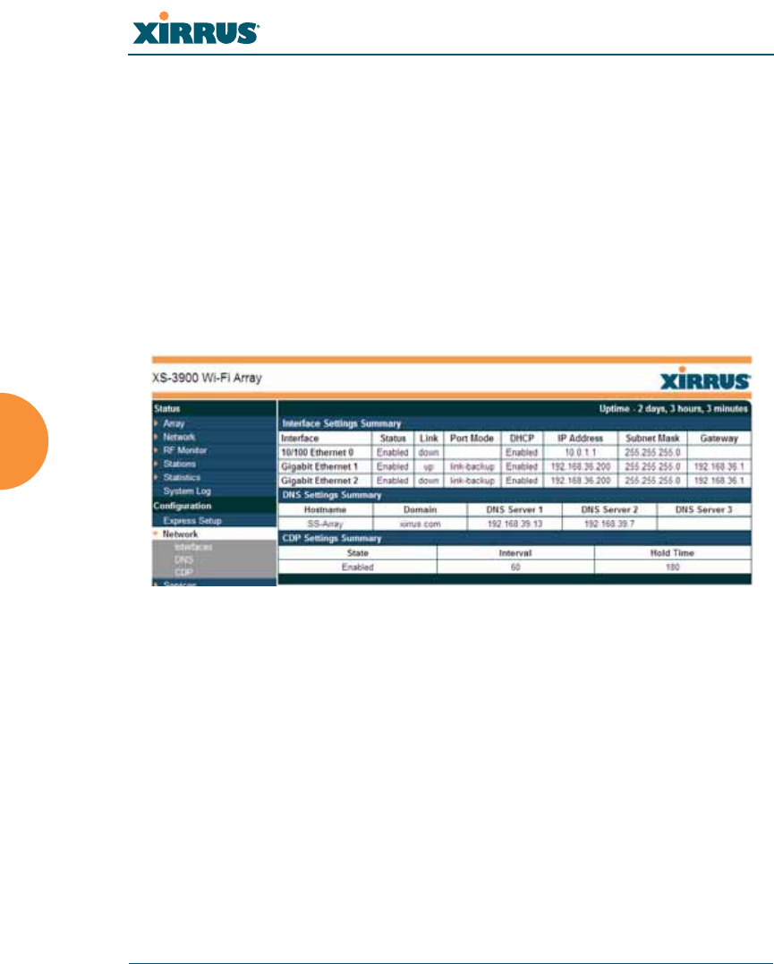
Wi-Fi Array
180 Configuring the Wi-Fi Array
This ends the Express Setup procedure.
Network
This is a status only window that provides a snapshot of the configuration
settings currently established for the 10/100 Ethernet 0 interface and the Gigabit 1
and Gigabit 2 interfaces. DNS Settings and CDP Settings (Cisco Discovery
Protocol) are summarized as well. You must go to the appropriate configuration
window to make changes to any of the settings displayed here (configuration
changes cannot be made from this window). You can click on any item in the
Interface column to “jump” to the associated configuration window.
Figure 105. Network Interfaces
WMI windows that allow you to change or view configuration settings associated
with the network interfaces include:
z“Network Interfaces” on page 181
z“DNS Settings” on page 188
z“CDP Settings” on page 189
See Also
DNS Settings
Network Interfaces
Network Status Windows
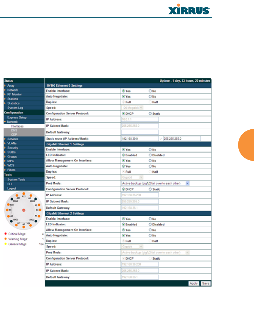
Wi-Fi Array
Configuring the Wi-Fi Array 181
Spanning Tree Status
Network Statistics
Network Interfaces
This window allows you to establish configuration settings for the 10/100 Fast
Ethernet interface and the Gigabit 1 and Gigabit 2 interfaces.
Figure 106. Network Settings
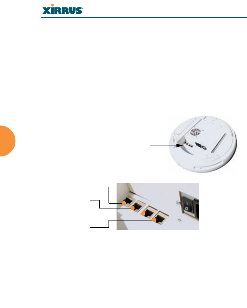
Wi-Fi Array
182 Configuring the Wi-Fi Array
When finished making changes, click on the Apply button to apply the new
settings to this session, or click Save to apply your changes and make them
permanent. When the status of an Ethernet or Gigabit port changes, a Syslog entry
is created describing the change.
Network Interface Ports
The following diagram shows the location of each network interface port on the
underside of the Array.
Figure 107. Network Interface Ports
Procedure for Configuring the Network Interfaces
Configure the Fast Ethernet and Gigabit 1 network interfaces (some Gigabit 2
settings cannot be configured separately and will mirror Gigabit 1). The fields for
each of these interfaces are the same, and include:
#Gigabit 2 settings will “mirror” Gigabit 1 settings (except for MAC
addresses) and cannot be configured separately.
Serial
Fast Ethernet
Gigabit 1
Gigabit 2

Wi-Fi Array
Configuring the Wi-Fi Array 183
1. Enable Interface: Choose Yes to enable this network interface (Fast
Ethernet, Gigabit 1 or Gigabit 2), or choose No to disable the interface.
2. LED Indicator: Choose Enabled to allow the LED for this interface to
blink with traffic on the port, or choose Disabled to turn the LED off.
The LED will still light during the boot sequence, then turn off. This
option is only available for the Gigabit interfaces.
3. Allow Management on Interface: Choose Yes to allow management of
this Array via the selected network interface, or choose No to deny all
management privileges for this interface. This option is only available for
the Gigabit interfaces—management is always enabled on the 10/100
interface (sometimes called the Management Port).
4. Auto Negotiate: This feature allows the Array to negotiate the best
transmission rates automatically. Choose Yes to enable this feature, or
choose No to disable this feature—the default is enabled. If you disable
the Auto Negotiate feature, you must define the Duplex and Speed
options manually (otherwise these options are not available).
a. Duplex: Data is transmitted in two directions simultaneously (for
example, a telephone is a full-duplex device because both parties can
talk and be heard at the same time). Half-duplex allows data
transmission in one direction at a time only (for example, a walkie-
talkie is a half-duplex device. If the Auto-Negotiate feature is
disabled, you can manually choose Half or Full duplex for your data
transmission preference.
b. Speed: If the Auto-Negotiate feature is disabled, you can manually
choose the desired data transmission speed from the pull-down list. If
configuring the Fast Ethernet interface the options are 10 Megabit or
100 Megabit. If configuring the Gigabit 1 or Gigabit 2 interfaces the
options are 100 Megabit or Gigabit.
5. Port mode: Select the desired behavior for the gigabit Ethernet ports from
the following options. For a more detailed discussion of the use of the
Gigabit ports and the options below, please see the Xirrus Gigabit Ethernet
Port Modes Application Note in the Xirrus Library.
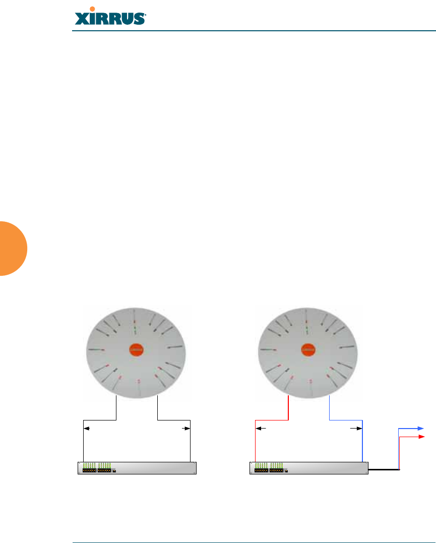
Wi-Fi Array
184 Configuring the Wi-Fi Array
a. Active Backup (gig1/gig2 failover to each other)—This mode
provides fault tolerance and is the default mode. Gigabit 1 acts as the
primary link. Gigabit2 is the backup link and is passive. Gigabit2
assumes the IP properties of Gigabit1. If Gigabit 1 fails the Array
automatically fails over to Gigabit2. When a failover occurs in this
mode, Gigabit2 issues gratuitous ARPs to allow it to substitute for
Gigabit1 at Layer 3 as well as Layer 2. See Figure 108 (a).
b. Aggregate Traffic from gig1 & gig2 using 802.3ad—The Array sends
network traffic across both gigabit ports to increase link speed to the
network. Both ports act as a single logical interface (trunk), using a
load balancing algorithm to balance traffic across the ports.
The destination IP address of a packet is used to determine its
outgoing adapter. For non-IP traffic (such as ARP), the last byte of the
destination MAC address is used to do the calculation. The network
switch must also support 802.3ad. If a port fails, the trunk degrades
gracefully—the other port still transmits. See Figure 108 (b).
Figure 108. Port Modes (a-b)
Gig1 Gig 2
Primary Link Secondary Link :
carries all traffic
if primary fails
Switch
Gig1 Gig 2
Switch
Links split traffic based on
destination address , using
802.3ad link aggregation
Destinations
(a) Active backup (b) Aggregate using 802.3ad
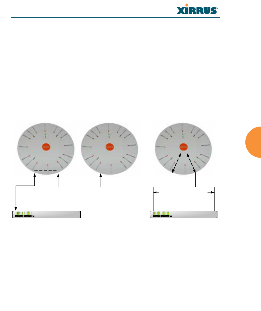
Wi-Fi Array
Configuring the Wi-Fi Array 185
c. Bridge traffic between gig1 & gig2—Traffic received on Gigabit1 is
transmitted by Gigabit2; similarly, traffic received on Gigabit2 is
transmitted by Gigabit1. This allows the Array to act as a wired
bridge and allows Arrays to be daisy-chained and still maintain
wired connectivity. See Figure 109 (c).
d. Transmit Traffic on both gig1 & gig2—Transmits incoming traffic on
both Gigabit1 and Gigabit2. Any traffic received on Gigabit1 or
Gigabit2 is sent to the onboard processor. This mode provides fault
tolerance. See Figure 109 (d).
Figure 109. Port Modes (c-d)
e. Load balance traffic between gig1 & gig2—This option provides
trunking, similar to option (b)—Aggregate Traffic from gig1 & gig2
using 802.3ad, but it uses a different load balancing algorithm to
determine the outgoing gigabit port. The outgoing port used is based
on an exclusive OR of the source and destination MAC address. Like
option (b), this mode also provides load balancing and fault
tolerance. See Figure 110 (e).
Gig1 Gig 2
Switch
Gig1 and Gig2 are bridged.
Traffic received on either link
is repeated to the other
Gig1 Gig 2
Gig1 Gig 2
Switch
Received wireless traffic is
sent to both links
Traffic from either link is
processed for transmission
(c) Bridge traffic (d) Transmit on both ports
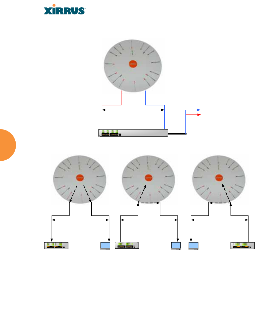
Wi-Fi Array
186 Configuring the Wi-Fi Array
Figure 110. Port Modes (e-f)
f. Mirror traffic on both gig1 & gig2—all traffic received on the Array
is transmitted out both Gigabit1 and Gigabit2. All traffic received on
Gigabit1 is passed on to the onboard processor as well as out
Gigabit2. All traffic received on Gigabit2 is passed on to the onboard
Gig1 Gig 2
Switch
Array load balances outgoing
traffic based on source and
destination address
Destinations
Gig1 Gig2
Received wireless traffic is
sent to both links
Gig 1 Gig2
Traffic from Gig1 is processed
for wireless transmission and
copied to Gig 2
Gig1 Gig2
Traffic from Gig 2 is processed
for wireless transmission and
copied to Gig1
Switch Switch Switch
Network
Analyzer
Network
Analyzer
Network
Analyzer
(e) Load balance traffic
(f) Mirror traffic

Wi-Fi Array
Configuring the Wi-Fi Array 187
processor as well as out Gigabit1. This allows a network analyzer to
be plugged into one port to capture traffic for troubleshooting, while
the other port provides network connectivity for data traffic. See
Figure 110 (f).
6. Configuration Server Protocol: Choose DHCP to instruct the Array to
use DHCP when assigning IP addresses to the Array, or choose Static IP
if you intend to enter IP addresses manually. If you select the Static IP
option you must specify the IP address, IP subnet mask and default
gateway.
a. IP Address: If you selected the Static IP option, enter a valid IP
address for the Array. To use any of the remote connections (Web,
SNMP, or SSH), a valid IP address must be established.
b. IP Subnet Mask: If you selected the Static IP option, enter a valid IP
address for the subnet mask (the default for Class C is 255.255.255.0).
The subnet mask defines the number of IP addresses that are
available on the routed subnet where the Array is located.
c. Default Gateway: If you selected the Static IP option, enter a valid IP
address for the default gateway. This is the IP address of the router
that the Array uses to transmit data to other networks.
7. Static Route (IP Address/Mask): (Fast Ethernet port only) The 10⁄100
Ethernet Port may be used for managing the Array out of band from the
Gigabit Ethernet ports. The 10⁄100 port will route only management
traffic, using a static route that may be configured using this field.
8. When done configuring all interfaces as desired, click on the Apply
button to apply the new settings to this session, or click Save to apply
your changes and make them permanent.
See Also
DNS Settings
Network
Network Statistics
Spanning Tree Status
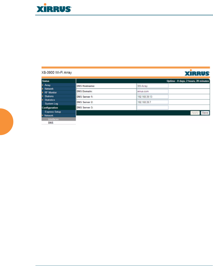
Wi-Fi Array
188 Configuring the Wi-Fi Array
DNS Settings
This window allows you to establish your DNS (Domain Name System) settings.
At least one DNS server must be set up if you want to offer clients associating
with the Array the ability to use meaningful host names instead of numerical IP
addresses. When finished, click on the Apply button to apply the new settings to
this session, or click Save to apply your changes and make them permanent.
Figure 111. DNS Settings
Procedure for Configuring DNS Servers
1. DNS Host Name: Enter a valid DNS host name.
2. DNS Domain: Enter the DNS domain name.
3. DNS Server 1: Enter the IP address of the primary DNS server.
4. DNS Server 2 and DNS Server 3: Enter the IP address of the secondary
and tertiary DNS servers (if required).
5. Click on the Apply button to apply the new settings to this session, or
click Save to apply your changes and make them permanent.
See Also
Network
Network Interfaces
Network Statistics
Spanning Tree Status
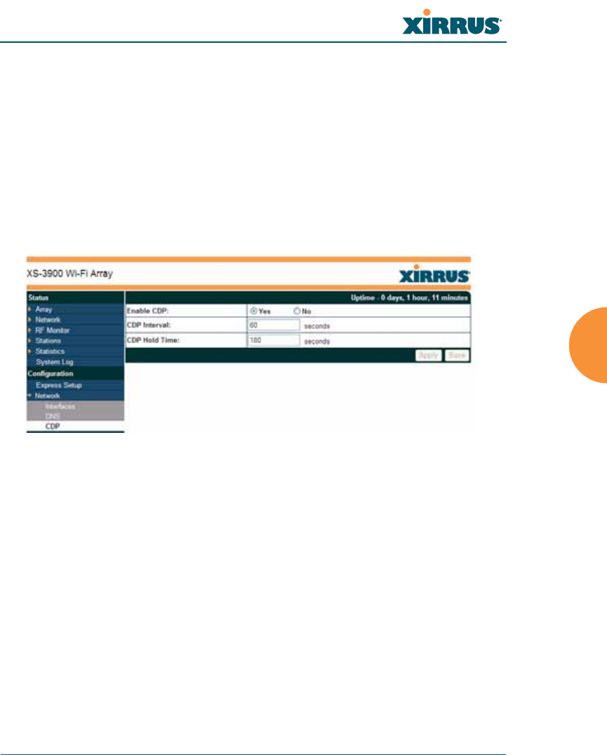
Wi-Fi Array
Configuring the Wi-Fi Array 189
CDP Settings
CDP (Cisco Discovery Protocol) is a layer 2 network protocol used to share
information (such as the device manufacturer and model, network capabilities,
and IP address) with other directly connected network devices. Wi-Fi Arrays can
both advertise their presence by sending CDP announcements, and gather and
display information sent by neighbors (see “CDP Neighbors” on page 140).
This window allows you to establish your CDP settings. When finished, click on
the Apply button to apply the new settings to this session, or click Save to apply
your changes and make them permanent.
Figure 112. CDP Settings
Procedure for Configuring CDP Settings
1. Enable CDP: When CDP is enabled, the Array sends out CDP
announcements of the Array’s presence, and gathers CDP data sent by
neighbors. When disabled, it does neither. CDP is enabled by default.
2. CDP Interval: The Array sends out CDP announcements advertising its
presence at this interval. The default is 60 seconds.
3. CDP Hold Time: CDP information received from neighbors is retained
for this period of time before aging out of the Array’s neighbor list. Thus,
if a neighbor stops sending announcements, it will no longer appear on
the CDP Neighbors window after CDP Hold Time seconds from its last
announcement. The default is 180 seconds.

Wi-Fi Array
190 Configuring the Wi-Fi Array
See Also
CDP Neighbors
Network
Network Interfaces
Network Statistics
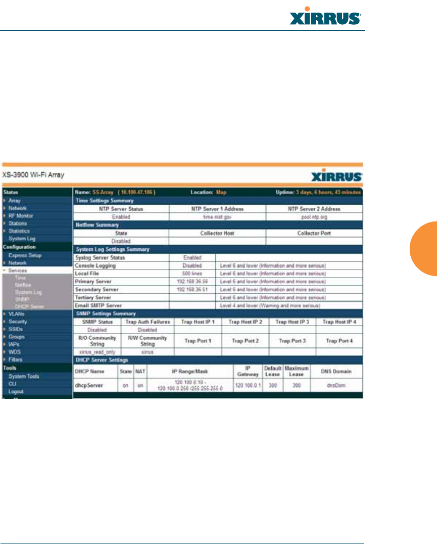
Wi-Fi Array
Configuring the Wi-Fi Array 191
Services
This is a status only window that allows you to review the current settings and
status for services on the Array, including DHCP, SNMP, Syslog, and Network
Time Protocol (NTP) services. For example, for the DHCP server, it shows each
DHCP pool name, whether the pool is enabled, the IP address range, the gateway
address, lease times, and the DNS domain being used. There are no configuration
options available in this window, but if you are experiencing issues with network
services, you may want to print this window for your records.
Figure 113. Services
The following sections discuss configuring services on the Array:
z“Time Settings (NTP)” on page 192
z“NetFlow” on page 194
z“System Log” on page 195
z“SNMP” on page 198
z“DHCP Server” on page 201
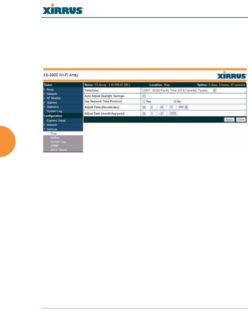
Wi-Fi Array
192 Configuring the Wi-Fi Array
Time Settings (NTP)
This window allows you to manage the Array’s time settings, including
synchronizing the Array’s clock with a universal clock from an NTP (Network
Time Protocol) server. Synchronizing the Array’s clock with an NTP server
ensures that Syslog time-stamping is maintained across all units.
Figure 114. Time Settings (Manual Time)
Procedure for Managing the Time Settings
1. Time Zone: Select the time zone you want to use (normally your local
time zone) from the pull-down list.
2. Auto Adjust Daylight Savings: Check this box if you want the system to
adjust for daylight savings automatically, otherwise leave this box
unchecked (default).
3. Use Network Time Protocol: select whether to set time manually or use
NTP to manage system time.
4. Setting Time Manually
a. Adjust Time (hrs:min:sec): If you are not using NTP, check this box if
you want to adjust the current system time. When the box is checked,
the time fields become active. Enter the revised time (hours, minutes,
seconds, am/pm) in the corresponding fields. If you don’t want to
adjust the current time, this box should be left unchecked (default).
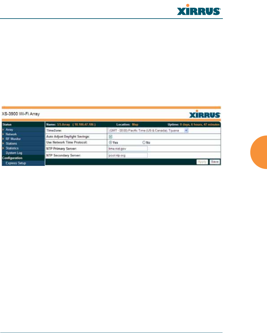
Wi-Fi Array
Configuring the Wi-Fi Array 193
b. Adjust Date (month/day/year): If you are not using NTP, check this
box if you want to adjust the current system date. When the box is
checked, the date fields become active. Enter the revised date (month,
day and year) in the corresponding fields. If you don’t want to adjust
the current date, this box should be left unchecked (default).
5. Using an NTP Server
a. NTP Primary Server: If you are using NTP, enter the IP address or
domain name of the NTP server.
Figure 115. Time Settings (NTP Time Enabled)
b. NTP Secondary Server: Enter the IP address or domain name of an
optional secondary NTP server to be used in case the Array is unable
to contact the primary server.
6. Click on the Apply button to apply the new settings to this session, or
click Save to apply your changes and make them permanent.
See Also
Services
SNMP
System Log
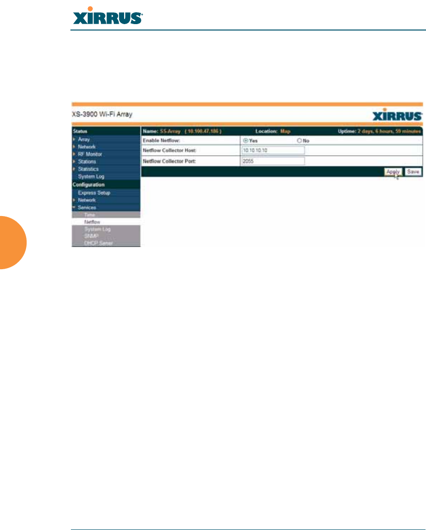
Wi-Fi Array
194 Configuring the Wi-Fi Array
NetFlow
This window allows you to enable or disable the sending of NetFlow information
to a designated collector. When enabled, the Array will send IP flow information
(traffic statistics) to the collector.
Figure 116. NetFlow
Procedure for Configuring NetFlow
1. Enable NetFlow: Choose Yes to enable NetFlow functionality, or choose
No to disable this feature.
2. NetFlow Collector Host (Domain or IP): If you enabled NetFlow, enter
the domain name or IP address of the collector.
3. NetFlow Collector Port: If you enabled NetFlow, enter the port on the
collector host to which to send data.
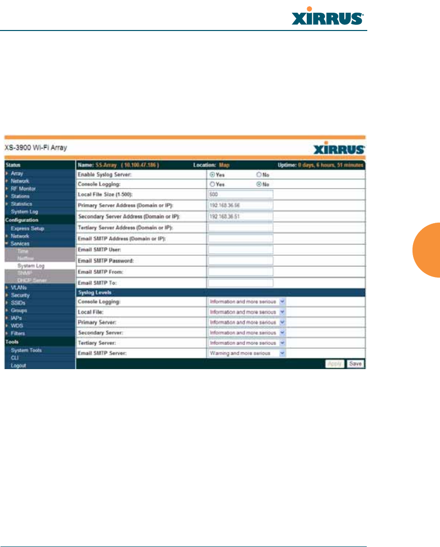
Wi-Fi Array
Configuring the Wi-Fi Array 195
System Log
This window allows you to enable or disable the Syslog server, define primary,
secondary, and tertiary servers, set up email notification, and set the level for
Syslog reporting for each of the servers and for email notification—the Syslog
service will send Syslog messages that are at the selected severity or above to the
defined Syslog servers and email address.
Figure 117. System Log
Procedure for Configuring Syslog
1. Enable Syslog Server: Choose Yes to enable Syslog functionality, or
choose No to disable this feature.
2. Console Logging: If you enabled Syslog, select whether or not to echo
Syslog messages to the console as they occur. If you enable console
logging, be sure to set the Console Logging level (see Step 7 below).

Wi-Fi Array
196 Configuring the Wi-Fi Array
3. Local File Size (1-500): Enter a value in this field to define how many
Syslog records are retained locally on the Array’s internal Syslog file. The
default is 500.
4. Primary Server Address (Domain or IP): If you enabled Syslog, enter the
domain name or IP address of the primary Syslog server.
5. Secondary/Tertiary Server Address (Domain or IP): If you enabled
Syslog, you may enter the domain name or IP address of one or two
additional Syslog servers to which messages will also be sent. (Optional)
6. Email Notification: The following parameters allow you to send an email
to a designated address each time a Syslog message is generated. The
email will include the text of the Syslog message.
a. Email SMTP Address (Domain or IP): The domain name or the IP
address of the SMTP server to be used for sending the email. Note
that this specifies the mail server, not the email recipient.
b. Email SMTP User/Email SMTP Password: Specify a user name and
password for logging in to an account on the mail server designated
in Step a.
c. Email SMTP From: Specify the “From” email address to be displayed
in the email.
d. Email SMTP To: Specify the entire email address of the recipient of
the email notification.
7. Syslog Levels: For each of the Syslog destinations, choose your preferred
level of Syslog reporting from the pull-down list. Messages with
criticality at the selected level and above will be shown. The default level
varies depending on the destination.
a. Console Logging: For messages to be echoed to the console, the
default level is Critical and more serious. This prevents large
numbers of non-critical messages from being displayed on the
console. If you set this level too low, the volume of messages may
make it very difficult to work with the CLI or view other output on
the console.

Wi-Fi Array
Configuring the Wi-Fi Array 197
b. Local File: For records to be stored on the Array’s internal Syslog file,
choose your preferred level of Syslog reporting from the pull-down
list. The default level is Debugging and more serious.
c. Primary Server: Choose the preferred level of Syslog reporting for the
primary server. The default level is Debugging and more serious.
d. Secondary/Tertiary Server: Choose the preferred level of reporting
for the secondary/tertiary server. The default level is Information
and more serious. (Optional)
e. Email SMTP Server: Choose the preferred level of Syslog reporting
for the email notifications. The default level is Warning and more
serious. This prevents your mailbox from being filled up with a large
number of less severe messages such as informational messages.
8. Click on the Apply button to apply the new settings to this session, or
click Save to apply your changes and make them permanent.
See Also
System Log Window
Services
SNMP
Time Settings (NTP)
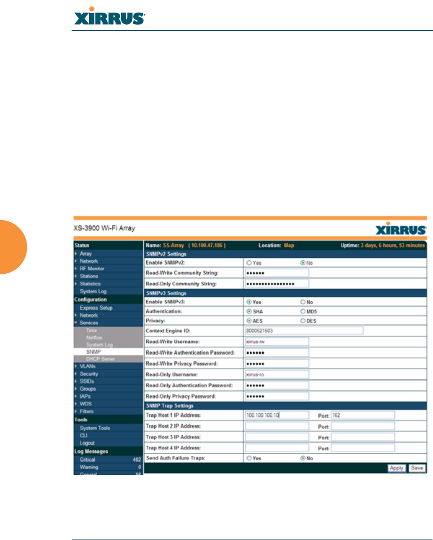
Wi-Fi Array
198 Configuring the Wi-Fi Array
SNMP
This window allows you to enable or disable SNMP v2 and SNMP v3 and define
the SNMP parameters. SNMP v2 allows remote management of the Array by the
Xirrus Management System (XMS). SNMP v3 was designed to offer much
stronger security. You may enable either SNMP version, neither, or both. If you
enable both, be aware that data and keys are not encrypted when SNMPv2 is
used.
NOTE: If you are managing your Arrays with XMS (the Xirrus Management System),
it is very important to use SNMP v2 and the correct Read-Write Community String
for proper operation of XMS with the Array. Both XMS and the Array must have the
same value for this string.
Figure 118. SNMP

Wi-Fi Array
Configuring the Wi-Fi Array 199
Procedure for Configuring SNMP
1. Enable SNMPv2: Choose Yes to enable SNMP v2 functionality, or choose
No to disable this feature. When used in conjunction with the Xirrus
Management System, SNMP v2 (not SNMP v3) must be enabled on each
Array to be managed with XMS. The default for this feature is Yes
(enabled).
2. SNMP Read-Write Community String: Enter the read-write community
string. The default is xirrus.
3. SNMP Read-Only Community String: Enter the read-only community
string. The default is xirrus_read_only.
4. Enable SNMPv3: Choose Yes to enable SNMP v3 functionality, or choose
No to disable this feature. The default for this feature is Yes (enabled).
5. Authentication: Select the desired method for authenticating SNMPv3
packets: SHA (Secure Hash Algorithm) or MD5 (Message Digest
Algorithm 5).
6. Privacy: Select the desired method for encrypting data: DES (Data
Encryption Standard) or the stronger AES (Advanced Encryption
Standard).
7. Context Engine ID: The unique identifier for this SNMP server. We
recommend that you do not change this value. The Context Engine ID
must be set if data collection is to be done via a proxy agent. This ID helps
the proxy agent to identify the target agent from which data is to be
collected.
8. SNMP Read-Write Username: Enter the read-write user name. This
username and password allow configuration changes to be made on the
Array. The default is xirrus-rw.
9. SNMP Read-Write Authentication Password: Enter the read-write
password for authentication (i.e., logging in). The default is xirrus-rw.
10. SNMP Read-Write Privacy Password: Enter the read-write password for
privacy (i.e., a key for encryption). The default is xirrus-rw.

Wi-Fi Array
200 Configuring the Wi-Fi Array
11. SNMP Read-Only Username: Enter the read-only user name. This
username and password do not allow configuration changes to be made
on the Array. The default is xirrus-ro.
12. SNMP Read-Only Authentication Password: Enter the read-only
password for authentication (i.e., logging in). The default is xirrus-ro.
13. SNMP Read-Only Privacy Password: Enter the read-only password for
privacy (i.e., a key for encryption). The default is xirrus-ro.
14. SNMP Trap Host IP Address: Enter the IP Address or domain name, as
well as the Port number, of an SNMP management station that is to
receive SNMP traps. You may specify up to four hosts that are to receive
traps.
15. Send Auth Failure Traps: Choose Yes to log authentication failure traps
or No to disable this feature.
16. Click on the Apply button to apply the new settings to this session, or
click Save to apply your changes and make them permanent.
See Also
Services
System Log
Time Settings (NTP)
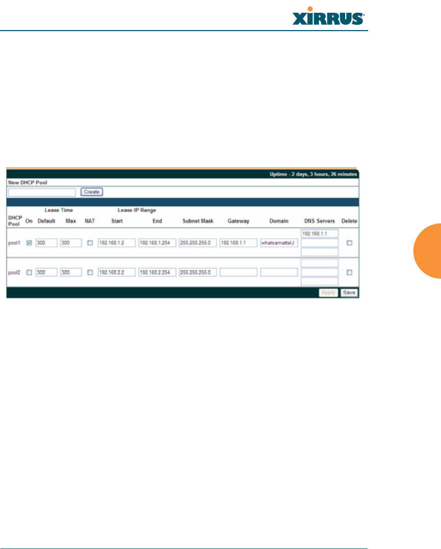
Wi-Fi Array
Configuring the Wi-Fi Array 201
DHCP Server
This window allows you to create, modify and delete DHCP (Dynamic Host
Configuration Protocol) pools and enable or disable DHCP server functionality.
DHCP allows the Array to provide wireless clients with IP addresses and other
networking information. The DHCP server will not provide DHCP services to the
wired side of the network.
If you enable the DHCP server, you need to define the DHCP lease time (default
and maximum) and establish the IP address range that the DHCP server can use.
Figure 119. DHCP Management
Procedure for Configuring the DHCP Server
1. New Internal DHCP Pool: Enter a name for the new DHCP pool, then
click on the Create button. The new pool ID is added to the list of
available DHCP pools.
2. On: Click this checkbox to make this pool of addresses available, or clear
it to disable the pool.
3. Lease Time—Default: This field defines the default DHCP lease time (in
seconds). The factory default is 300 seconds, but you can change the
default at any time.
4. Lease Time—Max: Enter a value (in seconds) to define the maximum
allowable DHCP lease time. The default is 300 seconds.

Wi-Fi Array
202 Configuring the Wi-Fi Array
5. Network Address Translation (NAT): Check this box to enable the
Network Address Translation feature.
6. Lease IP Range—Start: Enter an IP address to define the start of the IP
range that will be used by the DHCP server. The default is 192.168.1.100.
7. Lease IP Range—End: Enter an IP address to define the end of the IP
range that will be used by the DHCP server. The DHCP server will only
use IP addresses that fall between the start and end range that you define
on this page. The default is 192.168.1.200.
8. Subnet Mask: Enter the subnet mask for this IP range for the DHCP
server. The default is 255.255.255.0.
9. Gateway: If necessary, enter the IP address of the gateway.
10. Domain: Enter the DNS domain name. See also, “DNS Settings” on
page 188.
11. DNS Servers (1 to 3): Enter the IP address of the primary DNS server,
secondary DNS server and tertiary DNS server. See also, “DNS Settings”
on page 188.
12. Click Apply to apply the new settings to this session, or click Save to
apply your changes and make them permanent.
See Also
DHCP Leases
DNS Settings
Network Map
Wi-Fi Array
Configuring the Wi-Fi Array 203
VLANs
This is a status only window that allows you to review the current status of
assigned VLANs. A VLAN (Virtual LAN) is comprised of a group of devices that
communicate as a single network, even though they are physically located on
different LAN segments. Because VLANs are based on logical rather than
physical connections, they are extremely flexible. A device that is moved to
another location can remain on the same VLAN without any hardware
reconfiguration.
In addition to listing all VLANs, this window shows your settings for the Default
Route VLAN and the Native (Untagged) VLAN (Step 1 page 205).
Figure 120. VLANs
Understanding Virtual Tunnels
Xirrus Arrays support Layer 2 tunneling with Virtual Tunnels. This allows an
Array to use tunnels to transport traffic for one or more SSID-VLAN pairs onto a
single destination network through the Layer 3 core network.
The Array has low overhead and latency for VTun connections, with high
resilience. The Array performs all encryption and decryption in hardware,
maintaining wire-rate encryption performance on the tunnel.
#For a complete discussion of implementing Voice over Wi-Fi on the Array,
see the Xirrus Voice over Wi-Fi Application Note in the Xirrus Library.

Wi-Fi Array
204 Configuring the Wi-Fi Array
Virtual Tunnel Server (VTS)
Tunneling capability is provided by a Virtual Tunnel Server. You supply the server
and deploy it in your network using open-source VTun software, available from
vtun.sourceforge.net. To enable the Array to use tunneling for a VLAN, simply
enter the IP address, port and secret for the tunnel server as described in Step 10
on page 206.
VTun may be configured for a number of different tunnel types, protocols, and
encryption types. For use with Arrays, we recommend the following
configuration choices:
zTunnel Type: Ether (Ethernet tunnel)
zProtocol: UDP
zEncryption Type: select one of the encryption types supported by VTun
(AES and Blowfish options are available)
zKeepalive: yes
Client-Server Interaction
The Array is a client of the Virtual Tunnel Server. When you specify a VTS for a an
active VLAN-SSID pair, the Array contacts the VTS. The server then creates a
tunnel session to the Array. VTun encapsulated packets will cross the Layer 3
network from the Array to the VTS. When packets arrive at the VTS, they will be
de-encapsulated and the resultant packets will be passed to your switch with
802.1q VLAN tags for final Layer 2 processing. The process occurs in reverse for
packets traveling in the other direction.
We recommend that you enable the VTun keep-alive option. This will send a
keep-alive packet once per second to ensure that the tunnel remains active.
Tunnels can be configured to come up on demand but this is a poor choice for
Wi-Fi, since tunnel setup can take roughly 5-20 seconds and present a problem for
authentication.
Wi-Fi Array
Configuring the Wi-Fi Array 205
VLAN Management
This window allows you to assign and configure VLANs. After creating a new
VLAN (added to the list of VLANs), you can modify the configuration
parameters of an existing VLAN or delete a selected VLAN.
Figure 121. VLAN Management
Procedure for Managing VLANs
1. Default route: This option allows you to choose a default VLAN route
from the pull-down list. When you click Apply the VLAN you choose
will appear in the corresponding VLAN Number field. The IP Gateway
must be established for this function to work.
2. Native VLAN: This option allows you to choose the Native VLAN from
the pull-down list. When you click Apply the VLAN you choose will
appear in the corresponding VLAN Number field.
#The Wi-Fi Array supports dynamic VLAN assignments specified by
RADIUS policy settings. When RADIUS sends these assignments, the
Array dynamically assigns wireless stations to VLANs as requested.
VLAN tags on traffic are passed through the Array (i.e., VLAN tags are
not stripped). Once a station has been dynamically moved to a new
VLAN, it will be shown in the Stations window as a member of the new
VLAN. (Figure 82 on page 150)
It is critical to configure all VLANs to be used on the Array, even those
that will be dynamically assigned.