Cambium Networks XN8 Wireless LAN Array User Manual XN PDF
Xirrus, Inc. Wireless LAN Array XN PDF
Contents
Users Manual 2of5
Wi-Fi Array
64 Installing the Wi-Fi Array
Install the SNAPTOGGLE™ Toggle Bolts
2. At the locations you marked in Step 1, drill a 1/2 inch (13mm) hole (there
must be a minimum clearance behind the wall of 1 7/8 inches—48mm).
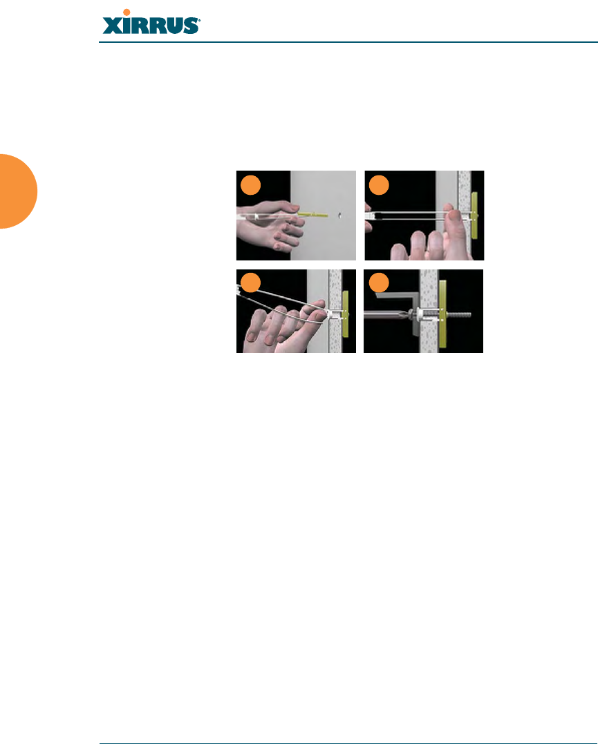
3. (Refer to Figure 35, graphic A) Hold the metal channel flat alongside the
plastic straps and slide the channel through the hole.
Figure 35. Installing the Toggle Bolts
4. (Refer to Figure 35, graphic B) Hold the strap handle between your
thumb and forefinger and pull towards you until the metal channel rests
flush behind the wall.
Using your other hand, now slide the plastic cap along the straps until the
flange of the cap is flush with wall.
The straps provide a one-way ratcheting mechanism (similar to a cable tie).
Ensure that the toggle bolt assembly is oriented correctly (as shown) before
sliding the plastic cap along the straps.
5. (Refer to Figure 35, graphic C) Break the straps at the wall, flush with the
flange of the cap. The straps can be broken by pushing them from side-to-
side and simply snapping them off.
Figure 35, Graphic D shows a cutaway example of how the toggle bolt is
used to secure an item to the wall (in our case, the item is the Wall
Mounting Bracket—secured to the wall with 5 toggle bolts.
Do not attach the Wall Mounting Bracket to the wall at this time.
AB
C D
Wi-Fi Array
Installing the Wi-Fi Array 65
Attach the Mounting Plate to the Wall Mounting Bracket
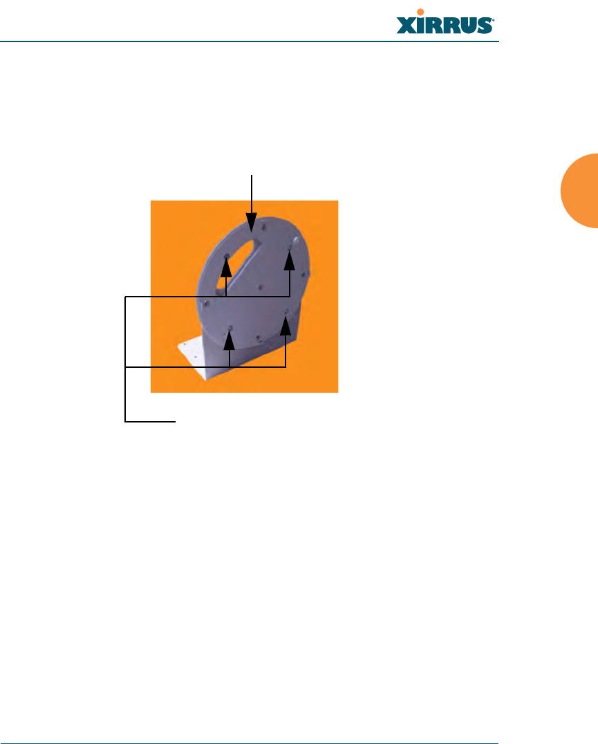
6. Secure the Wi-Fi Array’s mounting plate to the Wall Mounting Bracket, in
4 places. Tighten the bolts to a torque of 10–12 lbf.ft (1.38–1.66 kgf.m).
Do not overtighten the bolts.
Figure 36. Attaching the Wall Mounting Plate
Attach the Wall Mounting Bracket/Plate Assembly to the Wall
7. Secure the Wall Mounting Bracket (with attached Mounting Plate) to the
wall at the 5 toggle bolt anchors you created in Steps 1 through 5—using
all 5 places.
Mounting Plate
Secure (x4 bolt assemblies)

Wi-Fi Array
66 Installing the Wi-Fi Array
Mount the Array
8. Mount the Wi-Fi Array to the Wall Mounting Bracket in the same way
that you would mount the Array to a ceiling mount (the procedure is
identical). See “Attaching the Array to the Mounting Plate (XN16/XN8/
XN4)” on page 59.
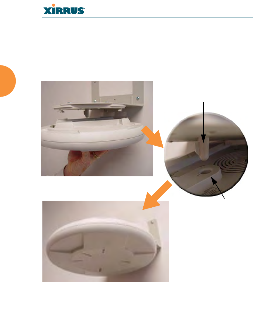
Figure 37. Mounting the Array on a Wall
See Also
Installation Workflow
Installing Your Wi-Fi Array
Mounting the Wi-Fi Array on a Wall (XN4)
Mounting the Array on a Ceiling
Securing the Array
#Figure 37 shows the orientation of the Wi-Fi Array when mounted on a wall.
It is not intended to show a fully installed Array.

Wi-Fi Array
Installing the Wi-Fi Array 67
Mounting the Wi-Fi Array on a Wall (XN4)
This procedure is applicable to the 4 radio models of the Wi-Fi Array (XN4). If you
are mounting a 16 radio model or 8 radio model, go to “Mounting the Array on a
Wall (XN16/XN8)” on page 62.
The wall mounting assembly kit is used to mount the XN4 Wi-Fi Array on a wall,
instead of the traditional ceiling mount—where mounting the Array on the
ceiling may be impractical at your location.
Kit Contents (Wall Mount Assembly)
The wall mount assembly kit includes the following items:
z5 x SNAPTOGGLE™ toggle bolts (for attaching the wall bracket to the
wall)
z4 x 1/4 inch bolt assemblies (for attaching the mounting plate to the wall
bracket)
zWall Mounting Bracket
Tools Required
zPower drill
z1/2 inch (13mm) drill bit
zCross head screwdriver
z1/4 inch nut wrench
zPencil
zLevel
Wi-Fi Array
68 Installing the Wi-Fi Array
Mark the Wall Position
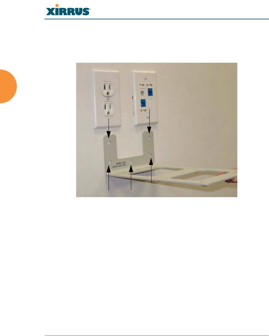
1. Use the Wall Mounting Bracket as a template and mark the locations on
the wall for the mounting holes.
Figure 38. Wall Mount—Marking the Holes
The bracket must be secured to the wall in 5 places, using the top 2 holes
and the bottom 3 holes (5 toggle bolts are provided).
When marking the holes, ensure that the mounting plate is level—you
may need assistance.
Install the SNAPTOGGLE™ Toggle Bolts
2. At the locations you marked in Step 1, drill a 1/2 inch (13mm) hole (there
must be a minimum clearance behind the wall of 1 7/8 inches—48mm).
Mark holes (5 places)

Wi-Fi Array
Installing the Wi-Fi Array 69
3. (Refer to Figure 39, graphic A) Hold the metal channel flat alongside the
plastic straps and slide the channel through the hole.
Figure 39. Installing the Toggle Bolts
4. (Refer to Figure 39, graphic B) Hold the strap handle between your
thumb and forefinger and pull towards you until the metal channel rests
flush behind the wall.
Using your other hand, now slide the plastic cap along the straps until the
flange of the cap is flush with wall.
The straps provide a one-way ratcheting mechanism (similar to a cable tie).
Ensure that the toggle bolt assembly is oriented correctly (as shown) before
sliding the plastic cap along the straps.
5. (Refer to Figure 39, graphic C) Break the straps at the wall, flush with the
flange of the cap. The straps can be broken by pushing them from side-to-
side and simply snapping them off.
Figure 39, Graphic D shows a cutaway example of how the toggle bolt is
used to secure an item to the wall (in our case, the item is the Wall
Mounting Bracket—secured to the wall with 5 toggle bolts).
Do not attach the Wall Mounting Bracket to the wall at this time.
AB
C D
Wi-Fi Array
70 Installing the Wi-Fi Array
Attach the Mounting Plate to the Wall Mounting Bracket
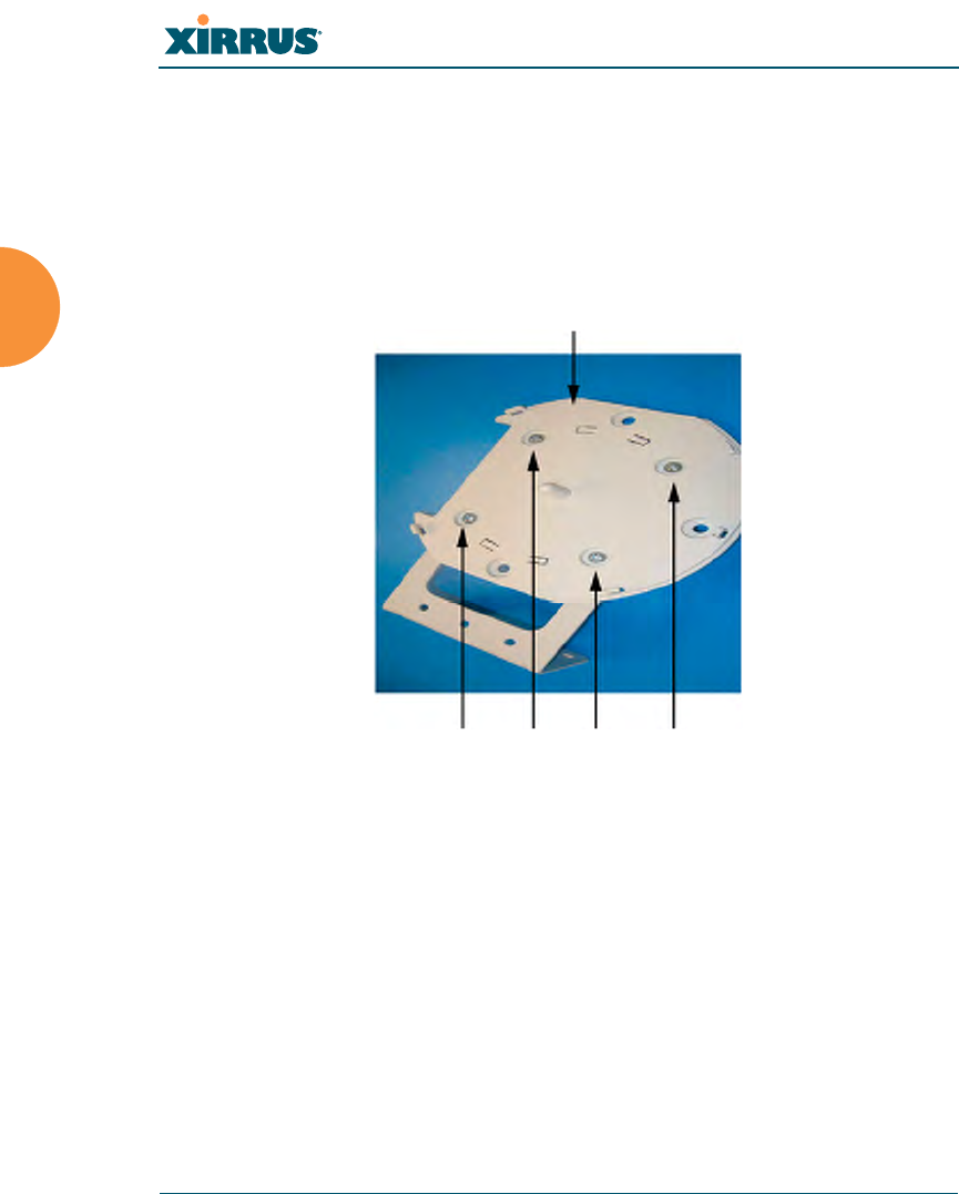
6. Secure the Wi-Fi Array’s mounting plate to the Wall Mounting Bracket, in
4 places.
Tighten the bolts to a torque of 10–12 ft-lb (1.38–1.66 kg.m).
Do not overtighten the bolts.
Figure 40. Attaching the Array Mounting Plate
Secure (x4 bolt assemblies)
Mounting Plate

Wi-Fi Array
Installing the Wi-Fi Array 71
Attach the Wall Mounting Bracket/Plate Assembly to the Wall
7. Secure the Wall Mounting Bracket (with attached Mounting Plate) to the
wall at the 5 toggle bolt anchors you created in Steps 2 through 5—using
all 5 places.
Figure 41. Attaching the Wall Mounting Bracket to the Wall
Secure with 5 toggle bolts
Wi-Fi Array
72 Installing the Wi-Fi Array
Mount the Array
8. Mount the Wi-Fi Array to the Wall Mounting Bracket by positioning the
key post (on the underside of the mounting bracket) into the key
receptacle on the underside of the Array.
When the key post is properly located, gently turn the Array in a
clockwise direction to secure the Array to the mounting plate.
Figure 42. Mounting the Array on a Wall
Key Post (Mounting Bracket)
Receptacle
Wi-Fi Array
Installing the Wi-Fi Array 73
Removing the Array
To remove the Array from the Wall Mount Assembly, simply apply a little upward
pressure to the Array, then gently turn the Array in a counterclockwise direction
to release the unit from the bracket.
See Also
Installation Workflow
Installing Your Wi-Fi Array
Mounting the Array on a Wall (XN16/XN8)
Mounting the Array on a Ceiling
Securing the Array
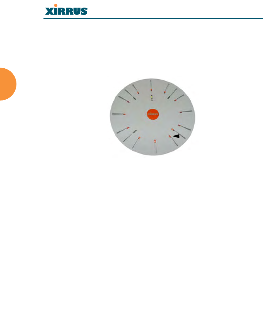
Powering Up the Wi-Fi Array
When powering up, the Array follows a specific sequence of LED patterns
showing the boot progress, and following a successful boot will provide extensive
status information.
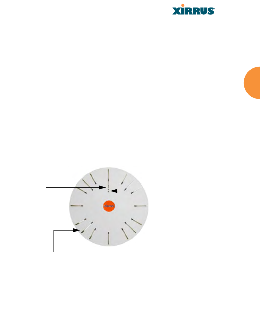
Figure 43. LED Locations (XN16)
Array LED settings may be altered or disabled entirely for diagnostic purposes or
for personal preference. Changes are made via the Array’s Command Line
Interface or the Web Management Interface—refer to “LED Settings” on page 227.
Status LED
Ethernet Activity
LEDs
IAP LEDs (x16)

Wi-Fi Array
74 Installing the Wi-Fi Array
Array LED Operating Sequences
Use the following tables to review the operating sequences of the Array’s LEDs.
LED Boot Sequence
The normal boot LED sequence is as follows:
Array Activity Status LED IAP LEDs
Power ON Blinking GREEN All OFF
Boot loader power ON
self-test
Blinking GREEN All ON
Image load from
compact FLASH
Blinking GREEN Spinning pattern
(rotate all to ON, then
all to OFF)
Image load failure Blinking RED All OFF
Hand off to ArrayOS Solid GREEN All OFF
System software
initialization
Solid GREEN Walking pattern
(LED rotating one
position per second)
Up and running Solid GREEN ON for IAPs that are
up, and OFF for IAPs
that are down

Wi-Fi Array
Installing the Wi-Fi Array 75
LED Operation when Array is Running
The normal LED operation when the Array is running is as follows:
See Also
Installation Prerequisites
Installation Workflow
Installing Your Wi-Fi Array
LED Status Reason
IAP LED is OFF IAP is down
IAP LED is solid ON IAP is up, but no associations and
no traffic
IAP LED heartbeat IAP is up, with stations
associated but no traffic
IAP LED flashing
Flashing at 10 Hz
Flashing at 5 Hz
Flashing at 2.5 Hz
IAP is up, passing traffic
Traffic > 1500 packets/sec
Traffic > 150 packets/sec
Traffic > 1 packet/sec
IAP LED is GREEN IAP is operating in the 2.4 GHz
band
IAP LED is ORANGE IAP is operating in the 5 GHz
band
IAP LED flashing ORANGE to
GREEN at 1 Hz
IAP abg2 is in monitor mode
(standard intrude detect)
Ethernet LEDs are dual color
Ethernet LED is ORANGE
Ethernet LED is GREEN
Transferring data at 1 Gbps
Transferring data at 10/100 Mbps
Wi-Fi Array
76 Installing the Wi-Fi Array
Establishing Communication with the Array
The Array can be configured through the Command Line Interface (CLI) or the
graphical Web Management Interface (WMI). You can use the CLI via the serial
management port, the Fast Ethernet port, or either of the Gigabit Ethernet ports.
You can use the WMI via any of the Array’s Ethernet ports.
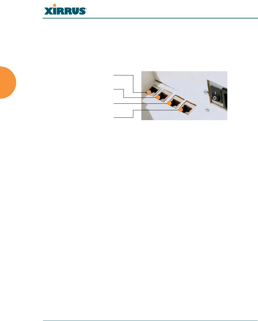
Figure 44. Network Interface Ports
Using the Serial Port
If using the serial port to make your connection, use serial settings of 8 bits, no
parity, no flow control, 1 stop bit (8N1) and a speed setting of 115200 baud. Use
the communication package of your choice.
Using the Ethernet Ports
By default, the Array's Ethernet interfaces use DHCP to obtain an IP address. If
the Array is booted and does not receive DHCP addresses on either the Fast
Ethernet or Gigabit Ethernet ports, the Fast Ethernet port will default to an IP
address of 10.0.1.1 and both Gigabit Ethernet ports will default to 10.0.2.1. If the
Array is connected to a network that provides DHCP addresses, the IP address
can be determined by the following two methods:
1. Examine the DHCP tables on the server and find the addresses assigned
to the Array (Xirrus MAC addresses begin with 000F7D).
2. Query the Array using the CLI via the serial port. Use the show ethernet
command to view the IP addresses assigned to each port.
Logging In
When logging in to the Array, use the default user name and password—the
default user name is admin, and the default password is admin.
Serial
Fast Ethernet
Gigabit 1
Gigabit 2
Wi-Fi Array
Installing the Wi-Fi Array 77
See Also
Installation Workflow
Performing the Express Setup Procedure
Powering Up the Wi-Fi Array
Performing the Express Setup Procedure
The Express Setup procedure allows you to establish global configuration settings
that will enable basic Array functionality. Any changes you make in this window
will affect all radios. When finished, click on the Apply button to apply the new
settings to this session, or click Save to apply and save your changes.
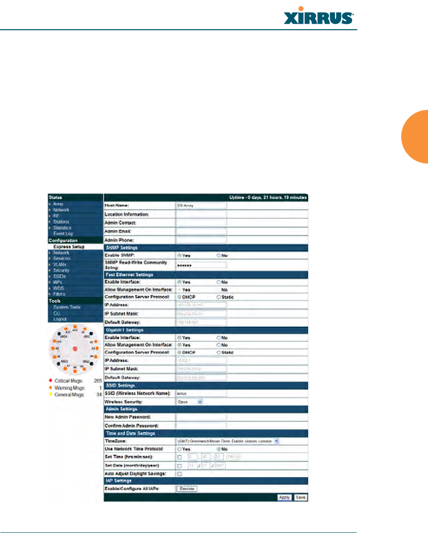
Figure 45. Express Setup

Wi-Fi Array
78 Installing the Wi-Fi Array
Procedure for Performing an Express Setup
1. Host Name: Specify a unique host name for this Array. The host name is
used to identify the Array on the network. Use a name that will be
meaningful within your network environment, up to 64 alphanumeric
characters. The default is Xirrus-WiFi-Array.
2. Location Information: Enter a brief but meaningful description that
accurately defines the physical location of the Array. In an environment
where multiple units are installed, clear definitions for their locations are
important if you want to identify a specific unit.
3. Admin Contact: Enter the name and contact information of the person
who is responsible for administering the Array at the designated location.
4. Admin Email: Enter the email address of the admin contact you entered
in Step 3.
5. Admin Phone: Enter the telephone number of the admin contact you
entered in Step 3.
6. Configure SNMP: Select whether to Enable SNMP on the Array, and set
the SNMP Read-Write Community String. The factory default value for
this is xirrus. If you are using the Xirrus Management System (XMS), this
string must match the string used by XMS.
7. Configure the Fast Ethernet (10/100 Megabit), Gigabit 1 and Gigabit 2
network interfaces. The fields for each of these interfaces are the same,
and include:
a. Enable Interface: Choose Yes to enable this network interface, or
choose No to disable the interface.
b. Allow Management on Interface: Choose Yes to allow management
of the Array via this network interface, or choose No to deny all
management privileges for this interface.
c. Configuration Server Protocol: Choose DHCP to instruct the Array
to use DHCP to assign IP addresses to the Array’s Ethernet interfaces,
or choose Static if you intend to enter IP addresses manually. If you
choose the Static IP option, you must enter the following information:

Wi-Fi Array
Installing the Wi-Fi Array 79
zIP Address: Enter a valid IP address for this Array. To use any of
the remote connections (Web, SNMP, or SSH), a valid IP address
must be used.
zIP Subnet Mask: Enter a valid IP address for the subnet mask
(the default is 255.255.255.0). The subnet mask defines the
number of IP addresses that are available on the routed subnet
where the Array is located.
zDefault Gateway: Enter a valid IP address for the default
gateway. This is the IP address of the router that the Array uses
to forward data to other networks.
8. SSID Settings: This section specifies the wireless network name and
security settings.
a. SSID (Wireless Network Name): The SSID (Service Set Identifier) is
a unique name that identifies a wireless network. All devices
attempting to connect to a specific WLAN must use the same SSID.
The default for this field is “xirrus.”
For additional information about SSIDs, go to the Multiple SSIDs
section of “Frequently Asked Questions” on page 334.
b. Wireless Security: Select the desired wireless security scheme (Open,
WEP, WPA, WPA2, or WPA-Both). WPA2 is recommended for the
best Wi-Fi security.
•Open—This option offers no data encryption and is not
recommended, though you might choose this option if clients are
required to use a VPN connection through a secure SSH utility,
like PuTTy.
•WEP (Wired Equivalent Privacy)—An optional IEEE 802.11
function that offers frame transmission privacy similar to a wired
network. WEP generates secret shared encryption keys that both
source and destination stations can use to alter frame bits to
avoid disclosure to eavesdroppers.

Wi-Fi Array
80 Installing the Wi-Fi Array
•WPA (Wi-Fi Protected Access)—A Wi-Fi Alliance standard that
contains a subset of the IEEE 802.11i standard, using TKIP or AES
as an encryption method and 802.1x for authentication.
•WPA2 (Wi-Fi Protected Access 2)—WPA2 is the follow-on
security method to WPA for wireless networks and provides
stronger data protection and network access control. It offers
Enterprise and consumer Wi-Fi users with a high level of
assurance that only authorized users can access their wireless
networks. Like WPA, WPA2 is designed to secure all versions of
802.11 devices, including 802.11a, 802.11b, 802.11g, and 802.11n,
multi-band and multi-mode.
•WPA-Both (WPA and WPA2)—This option makes use of both
WPA and WPA2.
For more information about security, including a full review of all
security options and settings, go to “Understanding Security” on
page 165.
c. Wireless Key/Passphrase: Depending on the wireless security
scheme you selected, enter a unique WEP key or WPA passphrase.
d. Confirm Key/Passphrase: If you entered a WEP key or WPA
passphrase, confirm it here.
9. Admin Settings: This section allows you to change the default password
for the Array.
a. New Admin Password: If desired, enter a new administration
password for managing this Array. Choose a password that is not
obvious, and one that you can remember. If you forget your
password, you must reset the Array to its factory defaults so that the
password is reset to admin (its default setting).
b. Confirm Admin Password: If you entered a new administration
password, confirm the new password here.

Wi-Fi Array
Installing the Wi-Fi Array 81
10. Time and Date Settings: This section specifies an optional time (NTP -
Network Time Protocol) server or modifies the system time if you’re not
using a server.
a. Time Zone: Select your time zone from the choices available in the
pull-down list.
b. Use Network Time Protocol: Check this box if you want to use an
NTP server to synchronize the Array’s clock. This ensures that syslog
time-stamping is maintained across all units. Without an NTP server
assigned (no universal clock), each Array will use its own internal
clock and stamp times accordingly, which may result in
discrepancies. If you check Yes, the NTP server fields are displayed. If
you don’t want to use an NTP server, leave this box unchecked
(default) and set the system time on the Array manually.
c. NTP Primary Server: If you are using NTP, enter the IP address or
domain name of the NTP server.
d. NTP Secondary Server: Enter the IP address or domain name of an
optional secondary NTP server to be used in case the Array is unable
to contact the primary server.
e. Set Time (hrs:min:sec): If you are not using NTP, check this box if
you want to adjust the current system time. When the box is checked,
the time fields become active. Enter the revised time (hours, minutes,
seconds, am/pm) in the corresponding fields. If you don’t want to
adjust the current time, this box should be left unchecked (default).
f. Set Date (month/day/year): If you are not using NTP, check this box if
you want to adjust the current system date. When the box is checked,
the date fields become active. Enter the revised date (month, day and
year) in the corresponding fields. If you don’t want to adjust the
current date, this box should be left unchecked (default).
g. Auto Adjust Daylight Savings: If you are not using NTP, check this
box if you want the system to adjust for daylight savings
automatically, otherwise leave this box unchecked (default).
Wi-Fi Array
82 Installing the Wi-Fi Array
11. IAP Settings:
Enable/Configure All IAPs: Click on the Execute button to enable and
auto configure all IAPs (a message displays the countdown time—in
seconds—to complete the auto-configuration task). When an IAP is
enabled, its LED is switched on.
Figure 46. LEDs are Switched On
12. Click on the Apply button to apply the new settings to this session
13. Click on the Save button to save your changes (otherwise your new
settings will not take effect).
This ends the Express Setup procedure.
See Also
Establishing Communication with the Array
Installation Prerequisites
Installation Workflow
Logging In
Multiple SSIDs
Security
LED on

Wi-Fi Array
The Web Management Interface 83
The Web Management Interface
This topic provides an overview of the Xirrus Wi-Fi Array’s embedded Web
Management Interface (WMI), used for establishing your network’s configuration
settings and wireless operating parameters. It also includes login instructions.
The following topics are discussed:
zAn Overview
zStructure of the WMI
zUser Interface
zLogging In
zApplying Configuration Changes
Wi-Fi Array
84 The Web Management Interface
An Overview
The WMI is an easy-to-use graphical interface to your Wi-Fi Array. It allows you
to configure the product to suit your individual requirements and ensure that the
unit functions efficiently and effectively.
Figure 47. Web Management Interface
Structure of the WMI
The content of the WMI has been organized by function and hierarchy, shown in
the following table in list form. Click on any item below to jump to the referenced
destination.

Wi-Fi Array
The Web Management Interface 85
Status Windows
Array Status Windows
Array Summary
Array Information
Array Configuration
Network Status Windows
Network Map
Spanning Tree Status
Routing Table
DHCP Leases
Connection Tracking/NAT
CDP Neighbors
RF Monitor Windows
IAPs
Spectrum Analyzer
Intrusion Detection
Station Status Windows
Stations
Location Map
RSSI
Signal-to-Noise Ratio (SNR)
Noise Floor
Statistics Windows
IAP Statistics
IAP Statistics Summary
Per-IAP Statistics
Network Statistics
VLAN Statistics
WDS Statistics
Filter Statistics
Station Statistics
System Log Window
Tool Windows
System Tools
CLI
Logout
Configuration Windows
Express Setup
Network
Network Interfaces
DNS Settings
CDP Settings
Services
Time Settings (NTP)
System Log
SNMP
DHCP Server
VLANs
VLAN Management
Security
Admin Management
Management Control
Access Control List
Global Settings
External Radius
Internal Radius
Rogue Control List
SSIDs
SSID Management
Groups
Group Management
IAPs
IAP Settings
Global Settings (IAP)
Global Settings .11an
Global Settings .11bgn
Advanced RF Settings
LED Settings
WDS
WDS Client Links
Filters
Filter Lists
Filter Management
Wi-Fi Array
86 The Web Management Interface
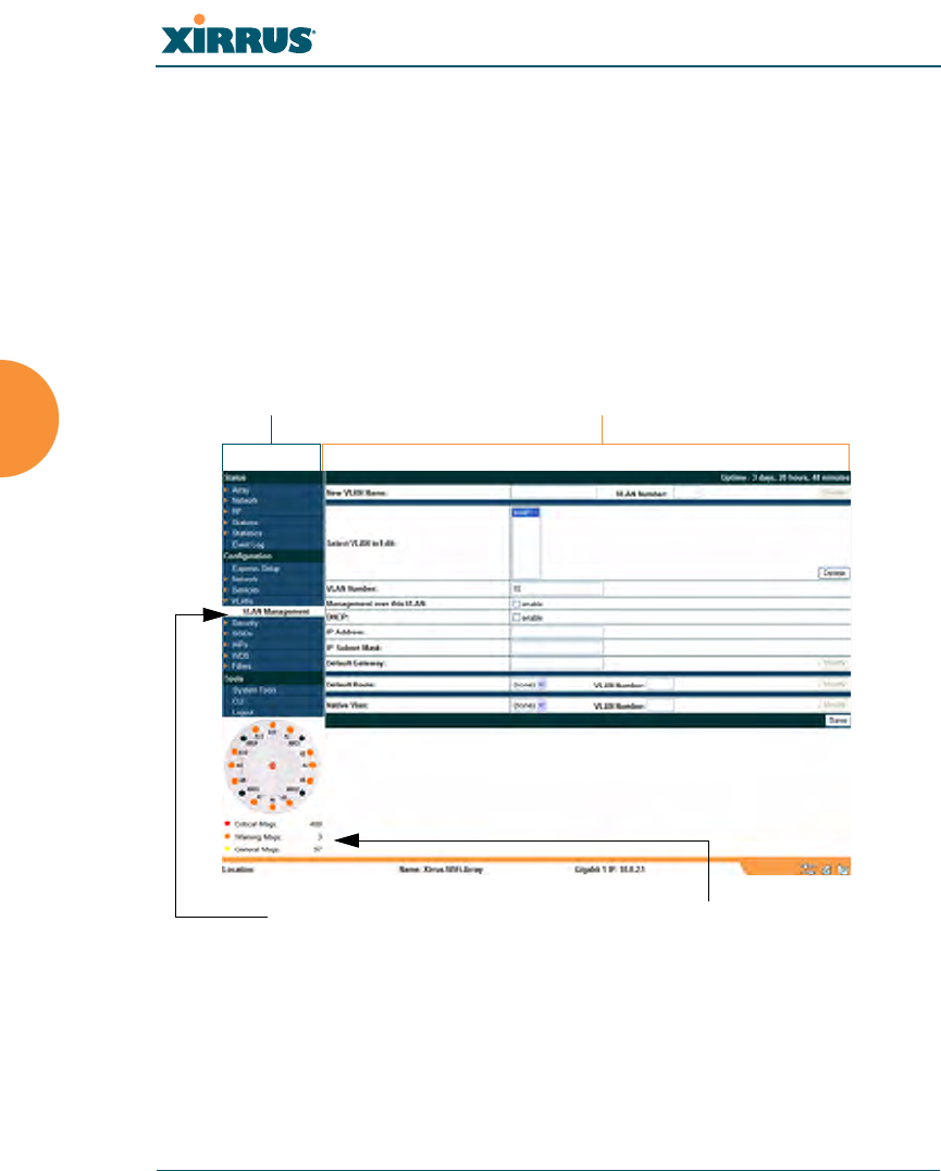
User Interface
The WMI has been designed with simplicity in mind, making navigation quick
and easy. In the following example, you’ll see that windows are divided into left
and right frames. The left frame contains configuration elements organized by
function (for example, radio interfaces, security, etc.), and where these functions
are sub-divided there is an associated pull-down menu. Also included in the left
frame are three counters that provide a running total of messages generated by
the ArrayOS syslog subsystem during your session—organized into Critical,
Warning and General messages.
Figure 48. WMI: Frames
The right frame contains the status information or configuration parameters for
the Wi-Fi Array. This is where you review the Array’s current status and activity
or input data (if you want to make changes).
Left frame Right frame
Pull-down menu Message counters
Wi-Fi Array
The Web Management Interface 87
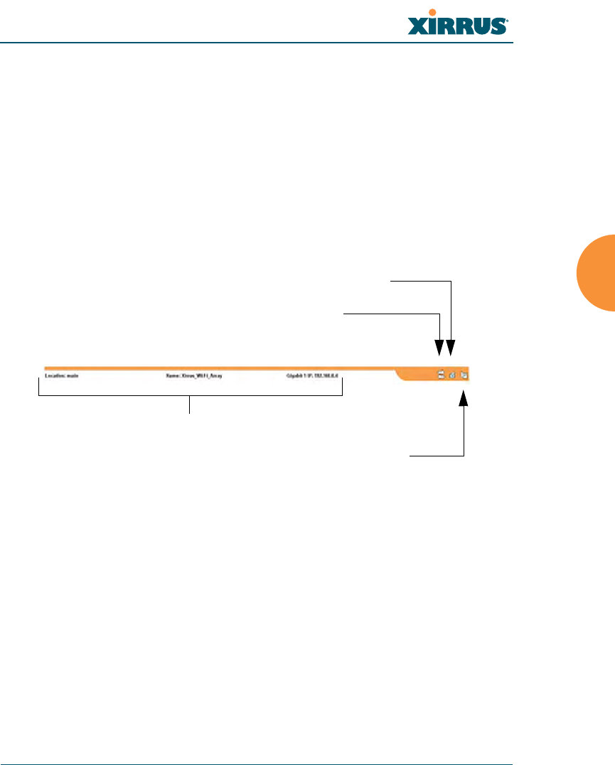
Status Bar
At the bottom of each window you will find a status bar containing information
about the Wi-Fi Array, including:
zLocation—displays the location information assigned to the unit.
zHost name—the host name assigned to this unit.
zNetwork interface IP address—the IP address of the network interface
that is currently being used.
Also included in the status bar is a Feedback button, a Print button and a Help
button.
Figure 49. WMI: Status Bar
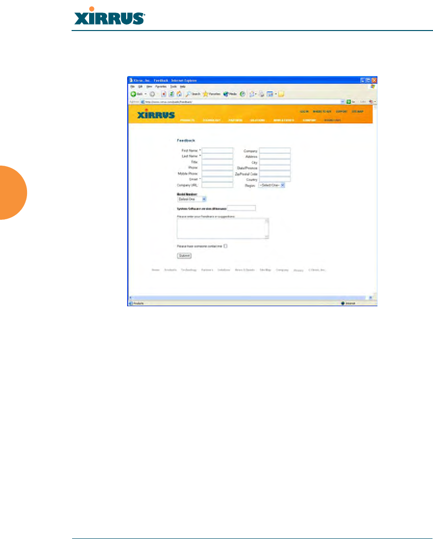
zClick on the Feedback button to generate a Web page that allows you to
submit your comments to Xirrus, Inc. You can also access the feedback
page at http://www.xirrus.com/public/feedback/. Refer to Figure 50 on
page 88 to see a sample of the feedback form.
zClick on the Print button to send a print file of the active window to your
local printer.
zClick on the Help button to access the Array’s online help system.
Submitting Your Comments
When submitting comments via the Feedback button, ensure that you provide as
much detail as possible, including your contact information, the product model
Status information
Print button
Help button
Feedback button
Wi-Fi Array
88 The Web Management Interface
number that the comment relates to, and the ArrayOS software version (if
known). When finished, click on the Submit button to submit your comment.
Figure 50. Feedback Form
Wi-Fi Array
The Web Management Interface 89
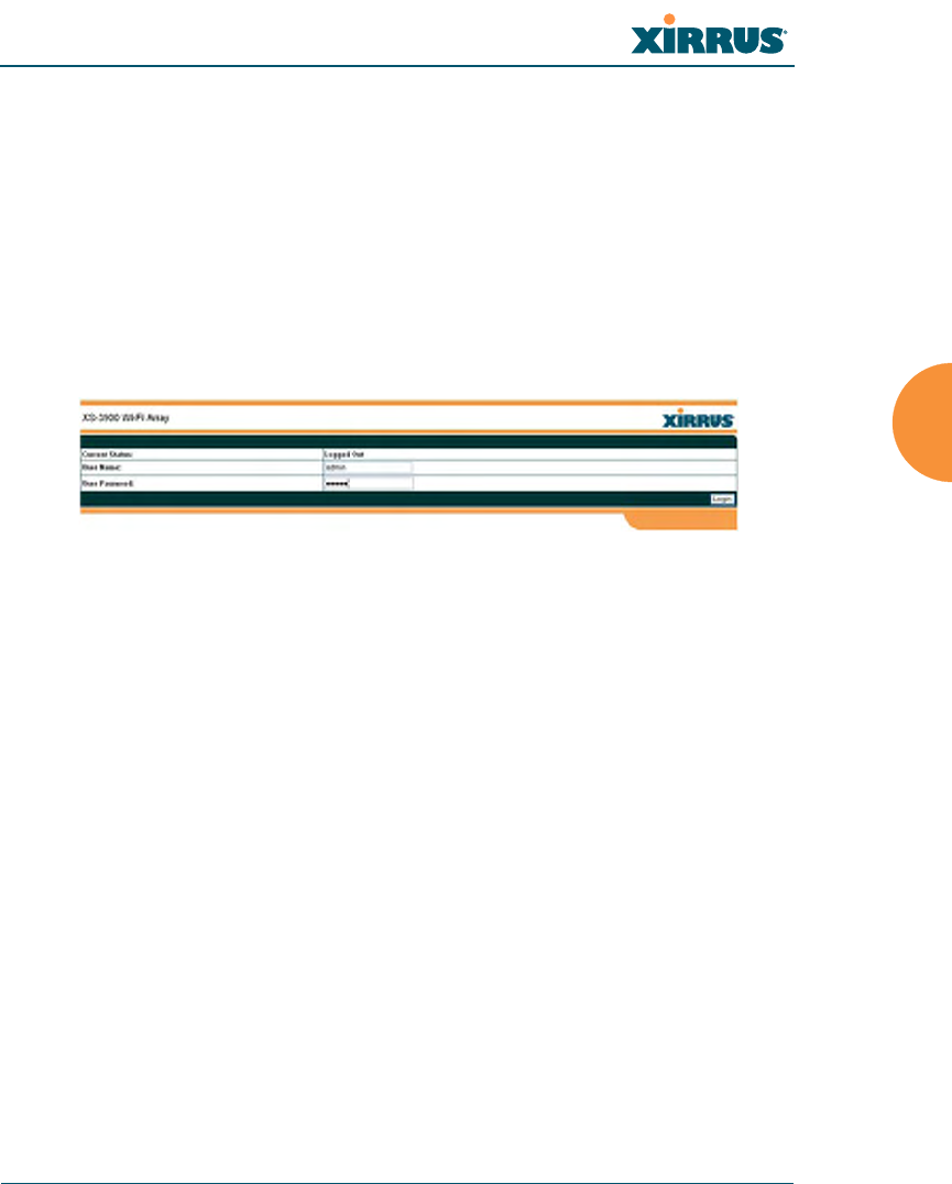
Logging In
Use this procedure to log in to the WMI via your Web browser.
1. Establish a network connection and open your Web browser.
2. Connect to the Wi-Fi Array via its default IP address (10.0.2.1 for both
Gigabit 1 and Gigabit 2 Ethernet ports) or via a DHCP assigned IP
address.
3. To log in to the Array’s Web Management Interface, enter admin when
prompted for a user name and password.
Figure 51. Logging In to the Wi-Fi Array
Applying Configuration Changes
When you have defined all your settings in any WMI configuration window, you
must click on the Apply button for the changes to take effect in the current
session, or click on the Save button to apply changes to this session and write
your changes, so they will be preserved after a reboot.
Character Restrictions
When inputting strings in the WMI (for example, assigning SSIDs, host name,
password, etc.), use only common alphanumeric characters. Do not use any of the
following characters:
&<>' “/ \
See Also
Key Features and Benefits
Wi-Fi Array Product Overview

Wi-Fi Array
90 The Web Management Interface

Wi-Fi Array
Viewing Status on the Wi-Fi Array 91
Viewing Status on the Wi-Fi
Array
These windows provide status information and statistics for your Array using the
product’s embedded Web Management Interface (WMI). You cannot make
configuration changes to your Array from these windows. The following topics
have been organized into functional areas that reflect the flow and content of the
Status section of the navigation tree in the left frame of the WMI.
z“Array Status Windows” on page 91
z“Network Status Windows” on page 98
z“RF Monitor Windows” on page 104
z“Station Status Windows” on page 111
z“Statistics Windows” on page 124
z“System Log Window” on page 132
Configuration and Tools windows are not discussed here. For information on
these windows, please see:
z“Configuring the Wi-Fi Array” on page 133
z“Using Tools on the Wi-Fi Array” on page 239
Array Status Windows
The following Array Status windows are available:
zArray Summary—displays information on the configuration of all Array
interfaces, including IAPs.
zArray Information—provides version/serial number information for all
Array components.
zArray Configuration—shows all configuration information for the Array
in text format.
Wi-Fi Array
92 Viewing Status on the Wi-Fi Array
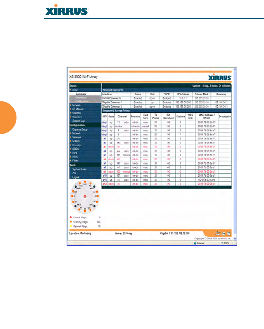
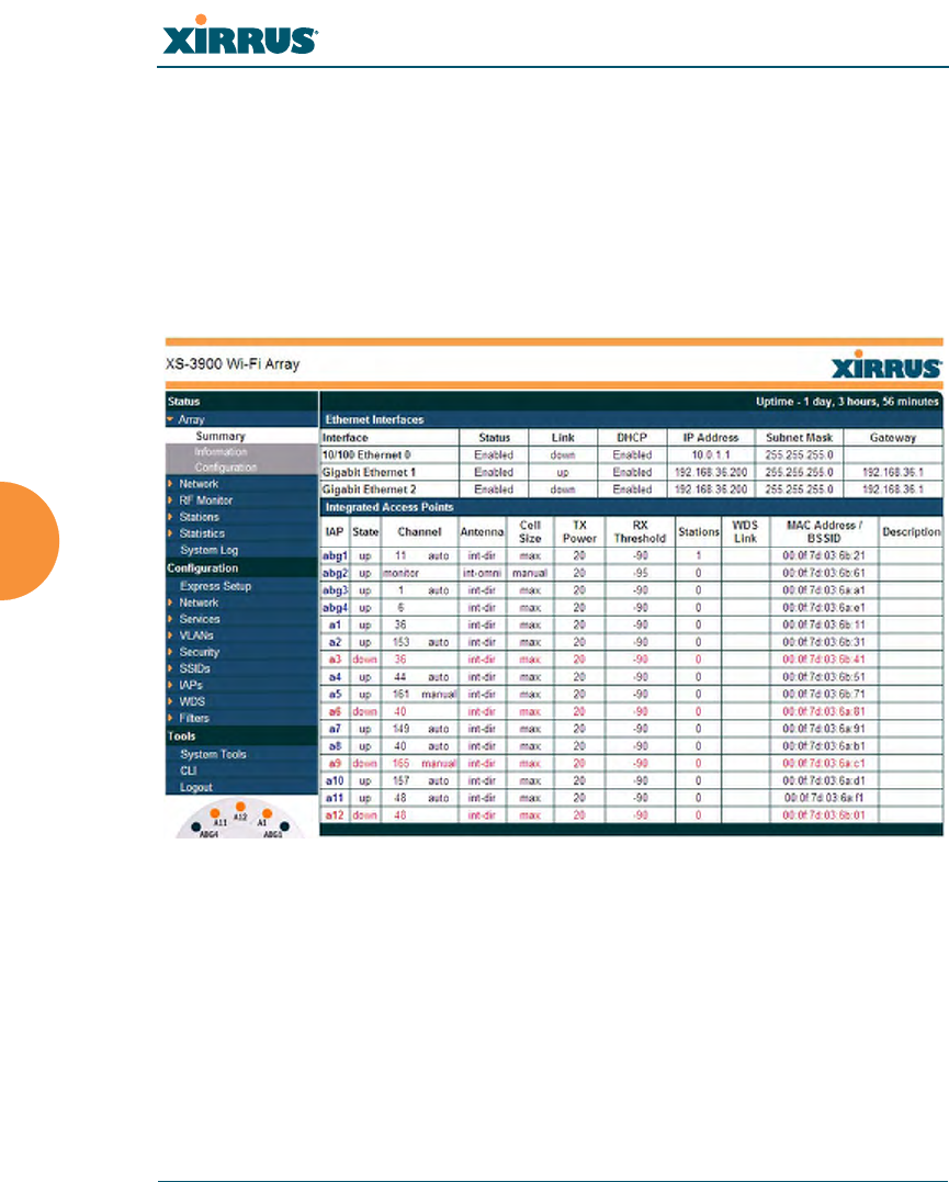
Array Summary
This is a status only window that provides a snapshot of the global configuration
settings for all Wi-Fi Array network interfaces and IAPs. You must go to the
appropriate configuration window to make changes to any of the settings
displayed here—configuration changes cannot be made from this window.
Clicking on an interface or IAP will take you to the proper window for making
configuration changes.
Figure 52. Array Summary

Wi-Fi Array
Viewing Status on the Wi-Fi Array 93
Content of the Array Summary Window
The Array Summary window is sub-divided into the Ethernet Interfaces section
and the Integrated Access Points (radio) section, providing you with the
following information:
zEthernet Interfaces Section
This section provides information about network interface devices. To
make configuration changes to these devices, go to “Network Interfaces”
on page 141.
•Interface: Lists the network interfaces that are available on the Array
(10/100 Ethernet 0, Gigabit Ethernet 1 and Gigabit Ethernet 2).
•Status: Shows the current state of each interface, either enabled or
disabled.
•Link: Shows whether the link on this interface is up or down.
•DHCP: Shows whether DHCP on this port is enabled or disabled.
•IP Address: Shows the current IP address assigned to each network
interface device.
•Subnet Mask: Shows the subnet mask, which defines the number of
IP addresses that are available on the routed subnet where the Array
is located.
•Gateway: Shows the IP address of the router that the Array uses to
transmit data to other networks.
zIntegrated Access Points Section
This section provides information about the Integrated Access Points
(IAPs) that are contained within the Array. How many IAPs are listed
depends on which product model you are using (16 IAPs for the XN16, 8
IAPs for the XN8, and 4 IAPs for the XN4). To make configuration
changes to these IAPs, go to “IAP Settings” on page 204.
•IAP: Lists the IAPs that are available on the Array.
•State: Shows the current state of each IAP, either up or down. IAPs
that are down are shown in RED. Figure 53 shows an example where
IAP a3 is down.
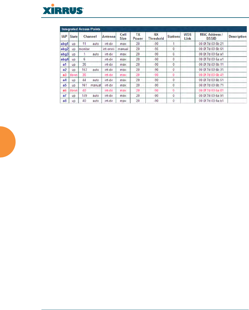
Wi-Fi Array
94 Viewing Status on the Wi-Fi Array
Figure 53. Disabled IAP (Partial View)
•Channel: Shows which channel each IAP is using, and the channel
setting. To avoid co-channel interference, adjacent radios should not
be using adjacent channels. To make channel selections for a specific
IAP, go to “IAP Settings” on page 204.
•Antenna: Shows which antenna is being used by each IAP.
•Cell Size: Indicates which cell size setting is currently active for each
IAP—small, medium, large, max, automatic, or manually defined by
you. The cell size of an IAP is a function of its transmit power and
determines the IAP’s overall coverage. To define cell sizes, go to “IAP
Settings” on page 204. For additional information about cell sizes and
the importance of planning for and defining the optimum cell sizes
for your Array, go to “Coverage and Capacity Planning” on page 32.

Wi-Fi Array
Viewing Status on the Wi-Fi Array 95
Figure 54. IAP Cells
•Tx Power: Shows the transit power for each IAP.
•Rx Threshold: Shows the receive threshold for each IAP.
•Stations: Informs you how many client stations are currently
associated with each IAP. The high-capacity XN16 can handle up to
64 concurrent users per individual IAP (1024 users per Array, or 960
when the monitor abg2 is enabled).
•WDS Link: The WDS Link on this radio (if any). See “WDS” on
page 229.
•MAC Address/BSSID: Shows the MAC address for each IAP.
•Description: The description (if any) that you set for this IAP.
Wi-Fi Array
96 Viewing Status on the Wi-Fi Array
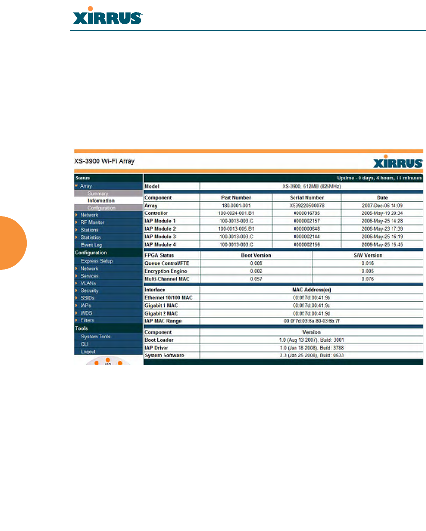
Array Information
This is a status only window that shows you the current firmware versions
utilized by the Array, the serial numbers assigned to each module, and MAC
addresses.
You cannot make configuration changes in this window, but if you are
experiencing issues with network services, you may want to print the content of
this window for your records.
Figure 55. Array Information
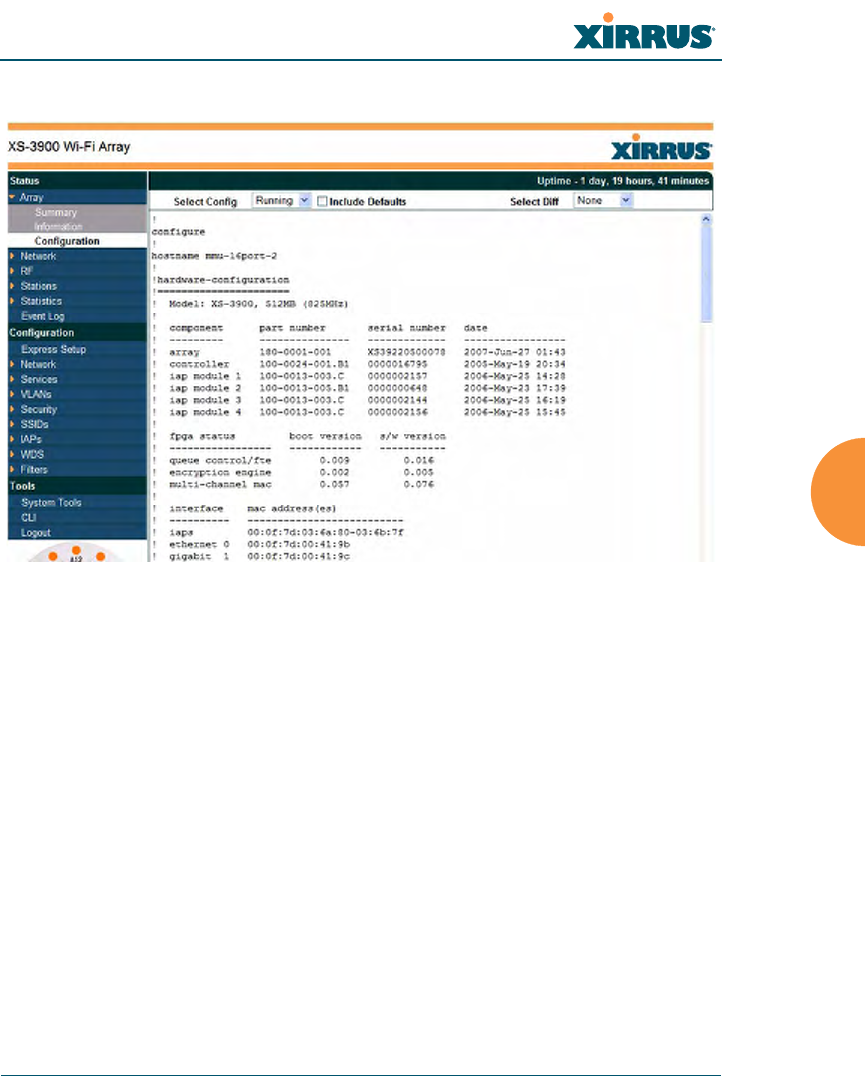
Array Configuration
This is a status only window that allows you to display the configuration settings
assigned to the Array, based on the following filter options:
zRunning—displays the current configuration (the one running now).
zSaved—displays the saved configuration from this session.
zLastboot—displays the configuration as it was after the last reboot.
Wi-Fi Array
Viewing Status on the Wi-Fi Array 97
zFactory—displays the configuration established at the factory.
Figure 56. Show Configuration
If you want to see just the differences between the Running, Saved, Lastboot, and
Factory configurations, you can do this by choosing a configuration option from
the Select Config pull-down menu then selecting an alternative configuration
option from the Select Diff pull-down menu.
You also have the option of including the default configuration settings in the
output. To do this, choose your configuration then click in the Include Defaults
check box. If Include Defaults is disabled, then only the changes from the default
configuration are shown.
Wi-Fi Array
98 Viewing Status on the Wi-Fi Array
Network Status Windows
The following Network Status windows are available:
zNetwork Map—displays information about this Array and neighboring
Arrays that have been detected.
zSpanning Tree Status—displays the spanning tree status of network
links on this Array.
zRouting Table—displays information about routing on this Array.
zDHCP Leases—displays information about IP addresses (leases) that the
Array has allocated to client stations.
zConnection Tracking/NAT—lists connections that have been established
for client stations.
zCDP Neighbors—lists neighboring network devices using Cisco
Discovery Protocol.
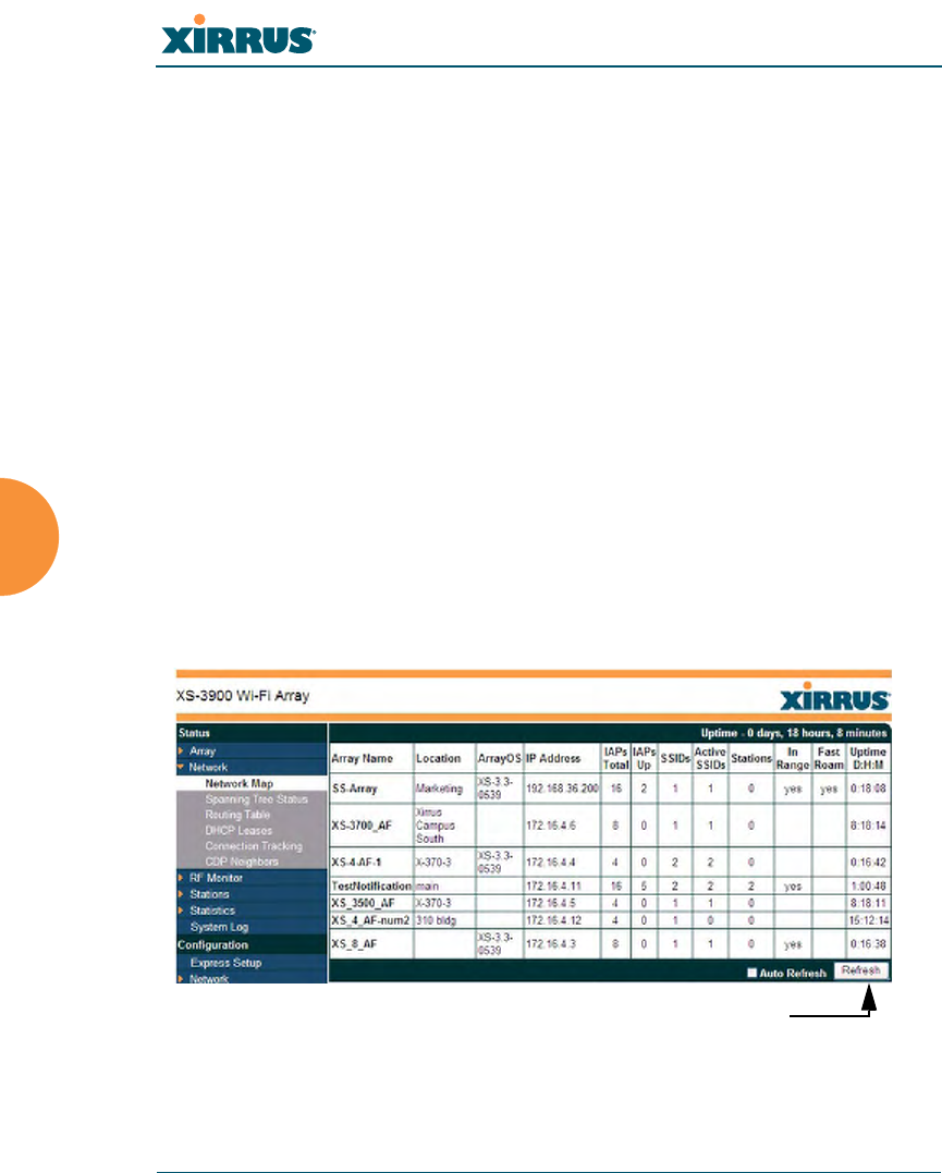
Network Map
This window offers detailed information about this Array and all neighboring
Arrays, including how the Arrays have been set up within your network.
Figure 57. Network Map
Refresh

Wi-Fi Array
Viewing Status on the Wi-Fi Array 99
You may sort the rows based on any column that has an active column header,
indicated when the mouse pointer changes to the hand icon . Click Refresh to
update the information at any time. Click Auto Refresh to instruct the Array to
refresh this window automatically.
Content of the Network Map Window
The network map includes the following status information for each Array:
zArray Name: The host name assigned to the Array. To establish the host
name, go to “Express Setup” on page 134.
zLocation: The location assigned to the Array. To establish the location
information, go to “Express Setup” on page 134.
zArray OS: The software version running on the Array.
zIP Address: The Array’s IP address. If DHCP is enabled, the Array’s IP
address is assigned by the DHCP server. If DHCP is disabled, you must
assign a static IP address. To enable DHCP or to assign a static IP address
for the Array, go to “Express Setup” on page 134.
zIAPs Total: The number of IAPs on the Array.
zIAPs Up: Informs you how many IAPs are currently up and running. To
enable or disable all IAPs, go to “Express Setup” on page 134. To enable
or disable individual IAPs, go to “IAP Settings” on page 204.
zSSIDs: Informs you how many SSIDs have been assigned for the Array.
To assign an SSID, go to “SSID Management” on page 189.
zActive SSIDs: Informs you how many SSIDs are enabled. To enable or
disable SSIDs, go to “SSID Management” on page 189.
zStations: Informs you how many stations are associated to the Array. To
associate (or disassociate) a station, go to “Stations” on page 112.
zIn Range: Informs you whether the Array is within wireless range of
another Wi-Fi Array.
zFast Roam: Informs you whether or not the Xirrus fast roaming feature is
enabled. This feature utilizes the Xirrus Roaming Protocol (XRP) ensuring
fast and seamless roaming capabilities between IAPs or Arrays at both
Wi-Fi Array
100 Viewing Status on the Wi-Fi Array
Layer 2 and Layer 3. To enable or disable fast roaming, go to “Global
Settings (IAP)” on page 209.
zUptime (D:H:M): Informs you how long the Array has been up and
running (in Days, Hours and Minutes).
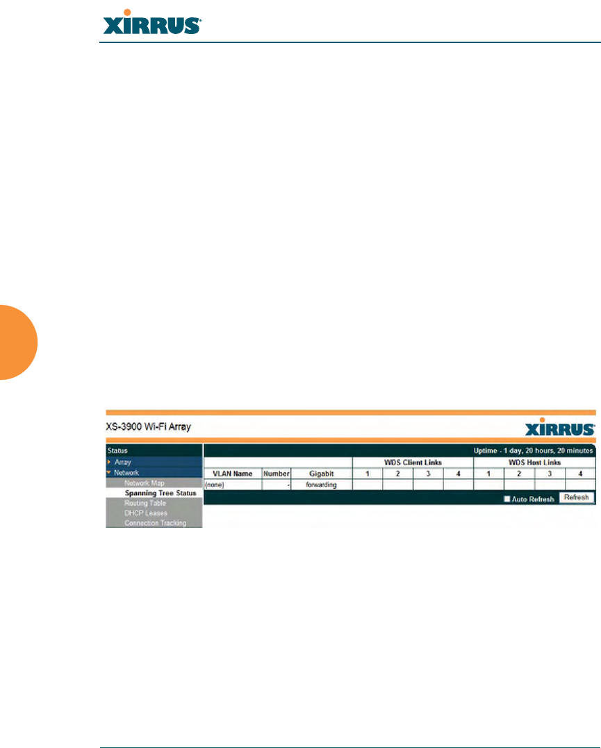
Spanning Tree Status
Multiple active paths between stations can cause loops in the network. If a loop
exists in the network topology, the potential exists for the duplication of
messages. The spanning tree protocol is a link management protocol that
provides path redundancy while preventing undesirable loops. For a wireless
network to function properly, only one active path can exist between two stations.
To facilitate path redundancy, the spanning tree protocol defines a tree that spans
all stations in the network and forces certain redundant data paths into a standby
(blocked) state. If one segment in the spanning tree becomes unreachable, the
spanning tree algorithm reconfigures the network topology and reestablishes the
link by activating the standby path. The spanning tree function is transparent to
client stations.
Figure 58. Spanning Tree Status
This window shows the spanning tree status (forwarding or blocked) for path
segments that terminate on this Array. You may sort the rows based on the VLAN
Name or Number columns by clicking the column header. Click Refresh to
update the information at any time. Click Auto Refresh to instruct the Array to
refresh this window automatically.
See Also
DNS Settings
Wi-Fi Array
Viewing Status on the Wi-Fi Array 101
Network
Network Interfaces
Network Statistics
Network Status Windows
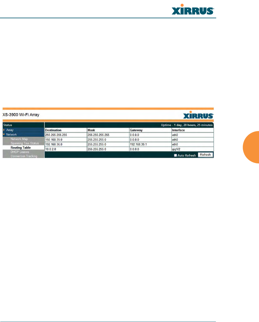
Routing Table
This status-only window lists the entries in the Array’s routing table. The table
provides the Array with instructions for sending each packet to its next hop on its
route across the network.
Figure 59. Routing Table
See Also
VLANs
Configuring VLANs on an Open SSID
Wi-Fi Array
102 Viewing Status on the Wi-Fi Array
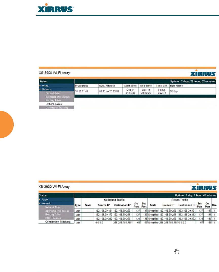
DHCP Leases
This status-only window lists the IP addresses (leases) that the Array has
allocated to client stations. For each, it shows the IP address assigned from one of
the defined DHCP pools, and the MAC address and host name of the client
station. The start and end time of the lease show how long the allocation is valid.
The same IP address is normally renewed at the expiration of the current lease.
Figure 60. DHCP Leases
See Also
DHCP Server
Connection Tracking/NAT
This status-only window lists the session connections that have been created on
behalf of clients. This table may also be used to view information about current
NAT sessions.
Figure 61. Connection Tracking
You may sort the rows based on any column that has an active column header,
indicated when the mouse pointer changes to the hand icon . Click Refresh to
Wi-Fi Array
Viewing Status on the Wi-Fi Array 103
update the information at any time. Click Auto Refresh to instruct the Array to
refresh this window automatically.
See Also
Filters
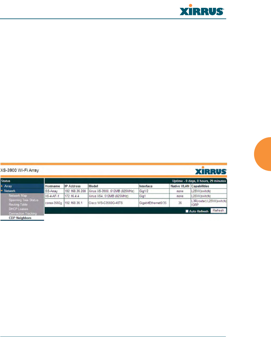
CDP Neighbors
This status-only window lists devices on the Array’s network that support the
Cisco Discovery Protocol (CDP). The Array performs discovery on the network
on an ongoing basis. This list shows the devices that have been discovered—Cisco
devices and other devices on the network that have CDP running. For each, it
shows the device’s host name, IP address, manufacturer and model name, the
device interface that is connected to the network (i.e., the port that was
discovered), and the network capabilities of the device (switch, router, supported
protocols, etc.).
Figure 62. CDP Neighbors
CDP must be enabled on the Array in order to gather and display this
information. See “CDP Settings” on page 149.

Wi-Fi Array
104 Viewing Status on the Wi-Fi Array
RF Monitor Windows
Every Wi-Fi Array includes an integrated RF spectrum analyzer as a standard
feature. The spectrum analyzer allows you to characterize the RF environment by
monitoring throughput, signal, noise, errors, and interference levels continually
per channel. This capability uses the built-in threat-sensor radio abg2. The
associated software is part of the ArrayOS.
The following RF Status windows are available:
zIAPs—displays current statistics and RF measurements for each of the
Array’s IAPs.
zSpectrum Analyzer—displays current statistics and RF measurements
for each of the Array’s channels.
zIntrusion Detection—displays rogue APs that have been detected by the
Array.
Wi-Fi Array
Viewing Status on the Wi-Fi Array 105
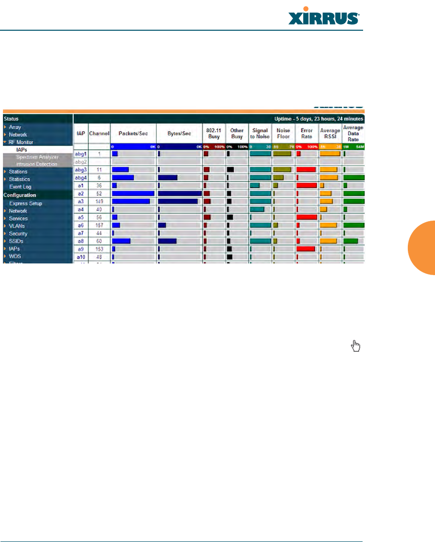
IAPs
The RF Monitor—IAPs window displays traffic statistics and RF readings
observed by each Array IAP (radio). Note that the data is an instantaneous
snapshot for the IAP—it is not an average or a cumulative total.
Figure 63. RF Monitor—IAPs
Figure 63 presents the data as a graphical display, enabled by selecting the Graph
checkbox on the lower left. If this option is not selected, data is presented as a
numerical table. You may sort the rows based on any column that has an active
column header, indicated when the mouse pointer changes to the hand icon .
Click Refresh to update the information at any time. Click Auto Refresh to
instruct the Array to refresh this window automatically.

Wi-Fi Array
106 Viewing Status on the Wi-Fi Array
Spectrum Analyzer
Spectrum analysis on Wi-Fi Arrays is a distributed capability that automatically
covers the entire Wi-Fi network, since a sensor is present in every unit. Arrays
monitor the network 24/7 and analyze interference anywhere in the network
from your desk. There’s no need to walk around with a device as with traditional
spectrum analyzers, thus you don’t have to be in the right place to find outside
sources that may cause network problems or pose a security threat. The Array
monitors all 802.11 radio bands (a/b/g), not just those currently used for data
transmission.
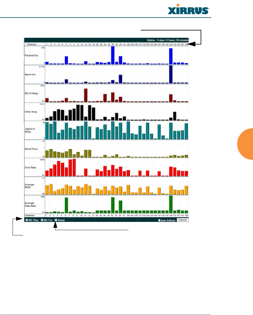
The RF Spectrum Analyzer window displays instantaneous traffic statistics and
RF readings for all channels, as measured by the Array’s abg2 radio. This differs
from the RF Monitor-IAPs window, which displays values measured by each IAP
radio for its current assigned channel. For the spectrum analyzer, the abg2 radio is
in a listen-only mode, scanning across all Wi-Fi channels. Each channel is scanned
in sequence, for a 250 millisecond interval per channel. The spectrum analyzer
window presents the data as a graphical display of vertical bar graphs for each
statistic as shown in Figure 64 (the default presentation), or horizontally as bar
graphs or numerical RF measurements. The measurements displayed are
explained in “Spectrum Analyzer Measurements” on page 108.
To display horizontal bar graphs, click the Rotate checkbox at the bottom of the
data window. In this rotated view, if you wish to view data as a numerical table,
click the Tex t checkbox. The text option is only available in the rotated view. You
may sort the rows based on any column that has an active column header,
indicated when the mouse pointer changes to the hand icon . Sorting is only
available in the rotated view.
At the bottom left of the frame, you may select whether to display only 802.11bgn
channels, 802.11an channels as shown, or both (both is the default). Note that the
data is an instantaneous snapshot—it is not an average or a cumulative total.
#The RF measurements for this feature are obtained by IAP abg2, which
must be set to monitor mode for any data to be available. See “IAP
Settings” on page 204.
Wi-Fi Array
Viewing Status on the Wi-Fi Array 107
Figure 64. RF Spectrum Analyzer
As an aid to viewing data for a particular channel, click the channel number. The
channel will be highlighted down the page (or across the page for a rotated view,
in both text and graph modes). Click additional channels to highlight them for
easy comparison. To remove the highlighting from a channel, click the channel
number again. Click Refresh to update the information at any time. Click Auto
Refresh to instruct the Array to refresh this window automatically.
Click Channel number to highlight
Select Channels to display Vertical / Horizontal Display

Wi-Fi Array
108 Viewing Status on the Wi-Fi Array
Spectrum Analyzer Measurements
The spectrum analyzer displays the following information:
zPackets/Sec: Total number of Wi-Fi packets per second on the channel,
both valid and errored packets.
zBytes/Sec: Total number of Wi-Fi bytes per second on the channel, valid
packets only.
z802.11 Busy: Percentage of time that 802.11 activity is seen on the channel.
zOther Busy: Percentage of time that the channel is unavailable due to
non-802.11 activity.
The total busy time (802.11 Busy plus Other Busy) will never total more
than 100%. The remaining time (100% minus total busy time) is quiet
time—the time that no activity was seen on the channel.
zSignal to Noise: Average SNR (signal to noise ratio) seen on the channel,
calculated from the signal seen on valid 802.11 packets less the noise floor
level. A dash value “-“ means no SNR data was available for the interval.
zNoise Floor: Average noise floor reading seen on the channel (ambient
noise). A dash value “-“ means no noise data was available for the
interval.
zError Rate: Percentage of the total number of Wi-Fi packets seen on the
channel that have CRC errors. The Error rate percentage may be high on
some channels since the monitor radio is set to receive at a very sensitive
level, enabling it to hear packets from devices at far distances.
zAverage RSSI: Average RSSI level seen on 802.11 packets received on the
channel. A dash value “-“ means no RSSI data was available for the
interval.
zAverage Data Rate: Average data rate over time (per byte, not per packet)
seen on 802.11 packets received on the channel. A dash value “-“ means
no data rate information was available for the interval. A higher date rate
(above 6 Mbps) typically indicates user data traffic on the channel.
Otherwise, the data rate reflects control packets at the lower basic rates.
Wi-Fi Array
Viewing Status on the Wi-Fi Array 109
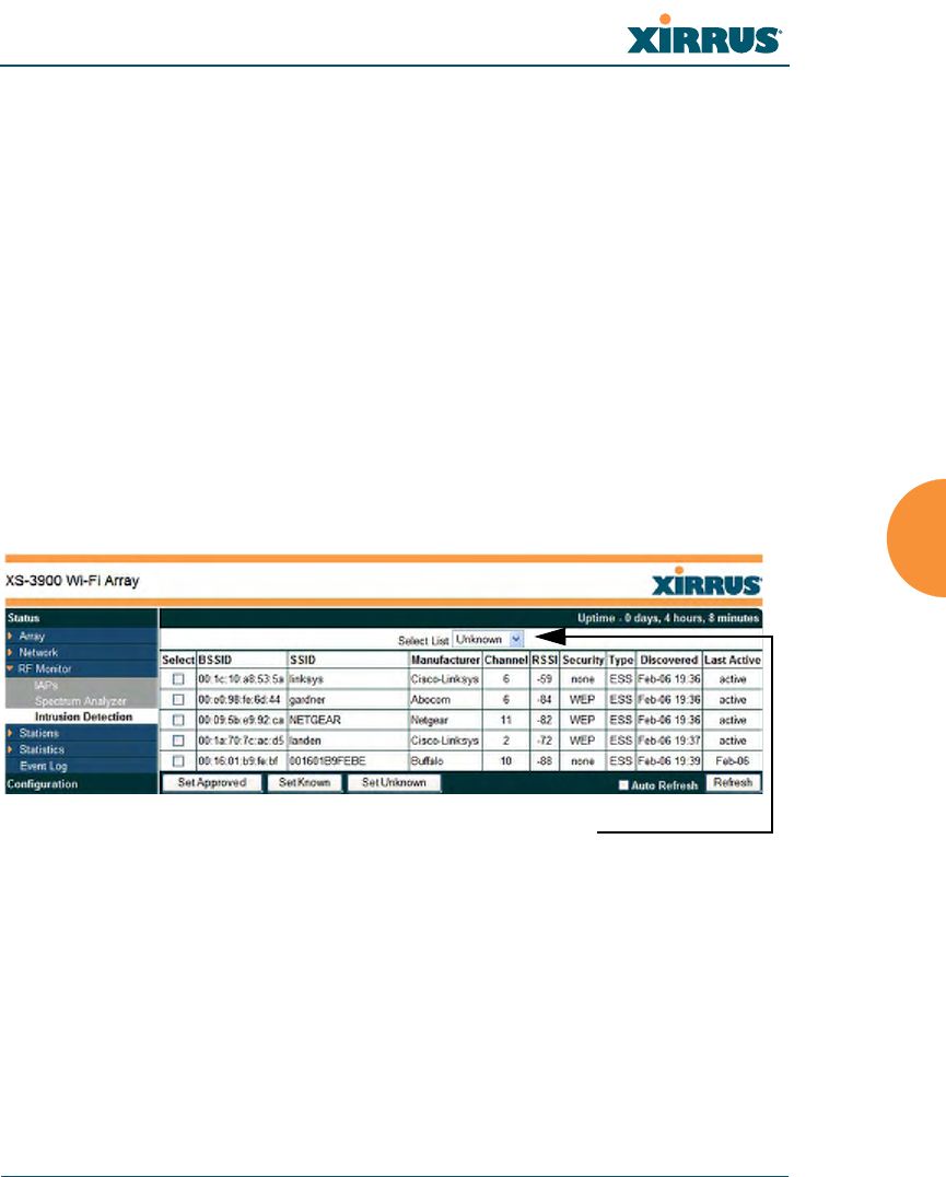
Intrusion Detection
This window displays all detected access points, according to the category you
select from the drop-down list at the top—either Unknown, Known or Approved.
This includes ad hoc access points (station-to-station connections). You can sort
the results based on the following parameters by clicking the desired column
header:
Figure 65. Intrusion Detection/Rogue AP List
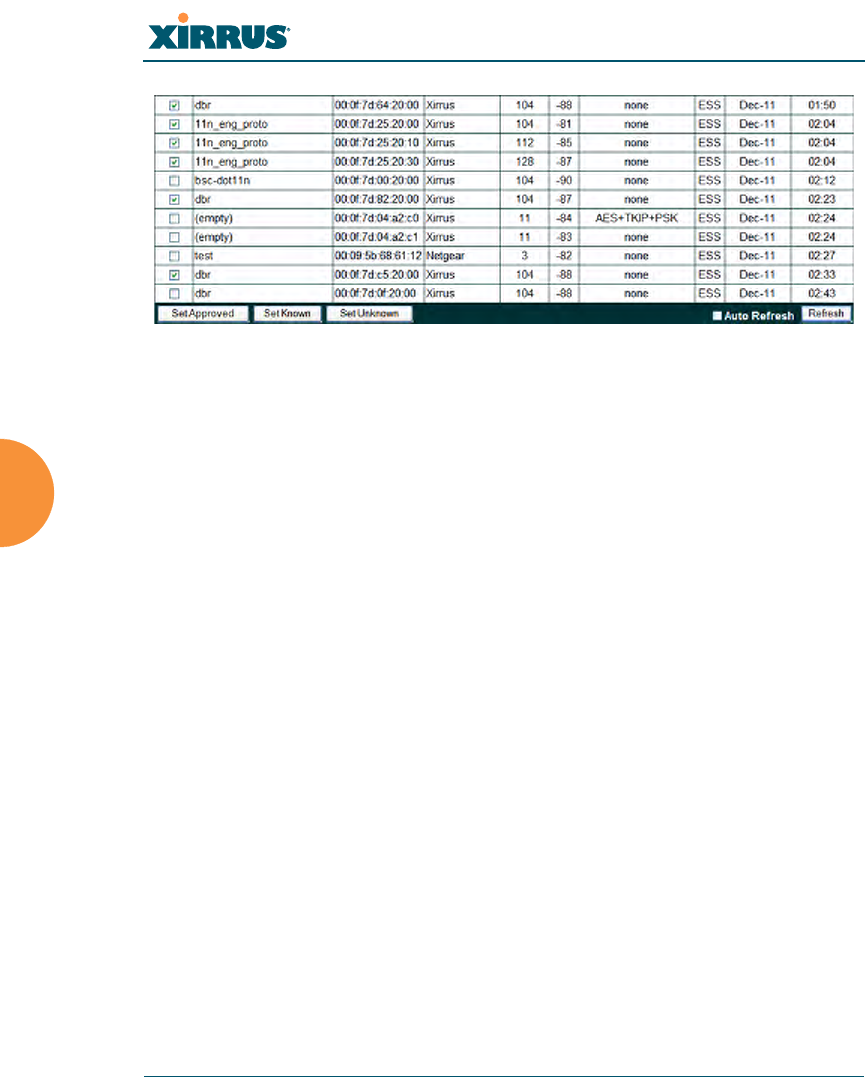
The Intrusion Detection window provides the easiest method for designating
rogue APs as Known. Approved, or Unknown. Choose one or more APs using the
checkbox in the Select column, then set whether they are Approved, Known, or
Unknown using the buttons on the lower left. (Figure 66)
zSSID zSecurity
zBSSID zType
zManufacturer zDiscovered
zChannel zLast Active
zRSSI
Select the type of AP to display
Wi-Fi Array
110 Viewing Status on the Wi-Fi Array
Figure 66. Categorizing APs
You can refresh the list at any time by clicking on the Refresh button, or click in
the Auto Refresh check box to instruct the Array to refresh the list automatically.
See Also
Network Map
Rogue Control List
SSIDs
SSID Management

Wi-Fi Array
Viewing Status on the Wi-Fi Array 111
Station Status Windows
The following Station Status windows are available:
zStations—this list describes all stations associated to the Array.
zLocation Map—displays a map showing the approximate locations of all
stations associated to the array.
zRSSI—for each associated station, this displays the Received Signal
Strength Indicator at each of the Array’s IAPs.
zSignal-to-Noise Ratio (SNR)—for each associated station, this displays
the SNR at each of the Array’s IAPs.
zNoise Floor—for each associated station, this displays the ambient noise
(silence) value at each of the Array’s IAPs.
Wi-Fi Array
112 Viewing Status on the Wi-Fi Array
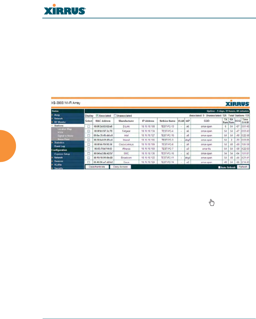
Stations
This status-only window shows client stations currently visible to the Array. You
may choose to view only stations that have associated to the Array, or only
stations that are not associated, or both, by selecting the appropriate checkboxes
above the list. The list shows the MAC address of each station, its manufacturer,
its IP address, its NetBIOS name, its VLAN, the IAP that the station is associated
with, the SSID used for the association, transmit and receive rates, the RSSI for
each station, and how long each association has been active (up time).
Figure 67. Stations
You may sort the rows based on any column that has an active column header,
indicated when the mouse pointer changes to the hand icon . Click again to
reverse the sort order. You may select a specific station and perform one of the
following actions by clicking the associated button:
zDeny Access: Sends a de-authentication frame to the selected station and
explicitly denies it access by adding its MAC address to the Deny List in
the Access Control List window. To permit access again, go to “Access
Control List” on page 172 and delete the station from the Deny list.
zDeauthenticate: Sends a de-authentication frame to the selected station.
The station may re-authenticate.
Click on the Refresh button to refresh the station list, or click in the Auto Refresh
check box to instruct the Array to refresh this window automatically.
Wi-Fi Array
Viewing Status on the Wi-Fi Array 113
See Also
Access Control List
Station Status Windows
Location Map
The Location Map shows the approximate locations of stations relative to this
Array. You may display stations associated to this Array, unassociated stations
(shown in gray), or both. The station count is shown on the left, above the map.
You may also choose to display 802.11an stations (shown in orange) or 802.11bgn
stations (shown in green), or both.
The map and Array are shown as if you were looking down on the Array from
above, say from a skylight on the roof. Thus the positions of the radios abg1 to
abg4 are a mirror image of the way they are typically drawn when looking at the
face of the Array. Radios abg1 to abg4 are marked (1 to 4) on the map to show the
orientation of the Array.
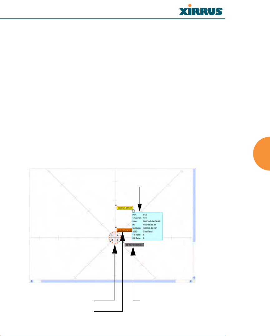
Figure 68. Location Map
Array
Associated Station
Unassociated Station
Hover mouse to
show details
Wi-Fi Array
114 Viewing Status on the Wi-Fi Array
A station is identified by its NetBIOS name if known, or else by its IP or MAC
address. Hover the mouse over a station to show detailed information. If multiple
stations are near each other, they will be displayed slightly offset so that one
station does not completely obscure another. You may minimize a station that is
not of interest by clicking it. Click it again for normal display. There is also a
Minimize All button.
You may replace the range-finder background image above with your own
custom image of the floorplan of the area served by the Array.
Controls and items displayed on the Location Map window
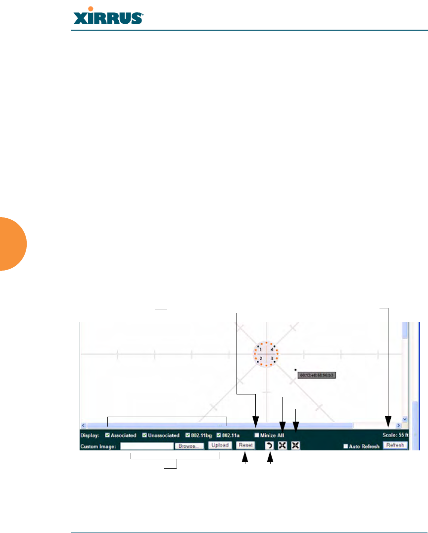
Figure 69. Controls for Location Map
#The controls for the Location Map are all at the bottom of the window and
take up a fair amount of width. If some of the controls shown in Figure 69 are
not visible, resize your browser window to be wider until all of the controls
appear.
Also, the Location Map has its own scroll bars in addition to the browser’s
scroll bars. If you narrow the browser window, the map’s scroll bar may be
hidden. Use the browser’s bottom scroll bar if you need to move it into view.
Stations to display Scale
Replace background
Minimize stations
Reset display Rotate map
Zoom in
Zoom out
Wi-Fi Array
Viewing Status on the Wi-Fi Array 115
zDisplay Associated/Unassociated: Select whether to display stations that
are associated to the Array, stations that are not associated, or both.
zDisplay 802.11bgn/802.11an: Select whether to display 802.11bgn
stations, or 802.11an stations, or both.
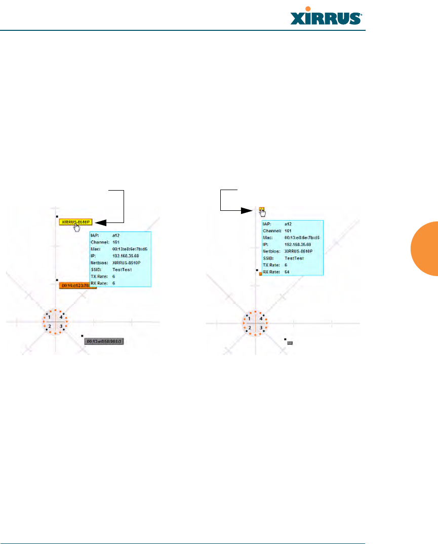
zMinimize All: All stations are shown by default with their NetBIOS
name or IP or MAC address. If the map is too cluttered, you can reduce
the display for each station to a small rectangle. You may still display
detailed information for the station by hovering over it. To enlarge all
rectangles, clear the Minimize All checkbox.
Figure 70. Minimizing stations
zScale: This view-only value shows the approximate distance represented
by each hashmark on the default map background. Scale is the rightmost
of the items displayed in the control area - you may need to scroll to the
right edge to see it.
zCustom Image: Use this feature to replace the default background image
with your own image of the floor plan of your location. Click the Browse
button and browse to the desired file on your computer. This may be a
.gif, .jpg, .jpeg., .png, .htm, or .html file. The scale of the file should be 100
feet per inch. Then click Upload (see below). For more information on
Normal station display Minimized station display
Wi-Fi Array
116 Viewing Status on the Wi-Fi Array
using the custom, image, see “Working with the Custom Image” on
page 116.
zUpload: After browsing to the desired custom image, click the Upload
button to install it. The map will be redisplayed with your new
background. No hash marks are added to the image display.
zReset: Click this button to restore the map display to the factory settings.
All attributes are restored—including the stations selected for display, the
scale, the rotation, and the background map.
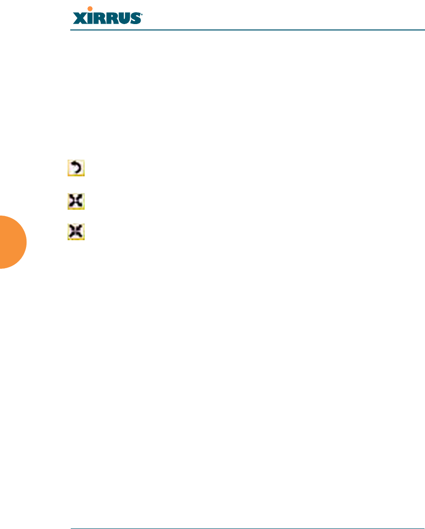
zRotate: Click this button to rotate the orientation of the entire map. It
rotates the map 45o counter-clockwise.
zEnlarge: Click this button to enlarge (zoom in on) the map. The displayed
Scale on the bottom right is updated with the new scale for the map.
zReduce: Click this button to reduce (zoom out on) the map.
The displayed Scale on the bottom right is updated with the new scale for
the map
zAuto Refresh: Instructs the Array to refresh this window automatically.
zRefresh: Updates the stations displayed.
See Also
Access Control List
Station Status Windows
Working with the Custom Image
After you have uploaded a custom image (see Custom Image and Upload in
“Controls and items displayed on the Location Map window” on page 114), you
should move the display of the Array on your map to correspond with its actual
location at your site. The Location Map window provides a special set of controls
for moving the location of the Array. These controls are displayed on the upper
right corner of the map (Figure 71). The location controls only appear when you
are using a custom image for you background. You will not see them if you are
using the default map background.
To move the Array on the map in a particular direction, click an arrow for the
desired direction on the location controls. The inner arrows move the Array by
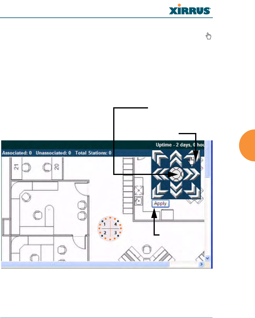
Wi-Fi Array
Viewing Status on the Wi-Fi Array 117
small steps; the outer arrows move it by larger steps. The arrows only work when
you position the mouse directly over them—make sure you see the hand icon .
If you need to return the Array to the center of the map, click the center of the
location controls. When you are done, click the Apply button to save the new
Array location, as well as the enlarge/reduce/rotate settings. These location
settings will persist for the duration of the current WMI session, but not after a
reboot (but the custom image will still be used after rebooting—whether or not
you click Apply).
Figure 71. Setting Array location on a Custom Image
Click an arrow to move
the Array
Array Location Controls
are at upper left of Map
Click here to move
Array to center of map
Apply Button
Wi-Fi Array
118 Viewing Status on the Wi-Fi Array
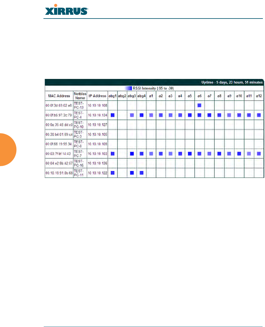
RSSI
For each station that is associated to the Array, the RSSI (Received Signal Strength
Indicator) window shows the station’s RSSI value as measured by each IAP. In
other words, the window shows the strength of the station’s signal at each radio.
You may choose to display Unassociated Stations as well with a checkbox at the
bottom of the window.
Figure 72. Station RSSI Values
By default, the RSSI is displayed numerically. You may display the relative
strength using color if you select Colorize Intensity, with the strongest signals
indicated by the most intense color. (Figure 72) If you select Graph, then the RSSI
is shown on a representation of the Array, either colorized or numerically based
on your selection. (Figure 73) The stations are listed to the left of the Array—click
on a station to show its RSSI values on the Array.
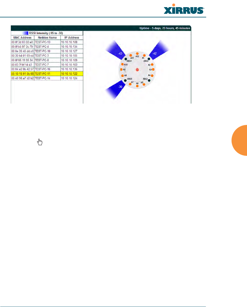
Wi-Fi Array
Viewing Status on the Wi-Fi Array 119
Figure 73. Station RSSI Values—Colorized Graphical View
In either graphical or tabular view, you may sort the rows based on any column
that has an active column header, indicated when the mouse pointer changes to
the hand icon . Click on the Refresh button to refresh the station list, or click in
the Auto Refresh check box to instruct the Array to refresh this window
automatically.
See Also
Station Status Windows
RF Monitor Windows
Wi-Fi Array
120 Viewing Status on the Wi-Fi Array
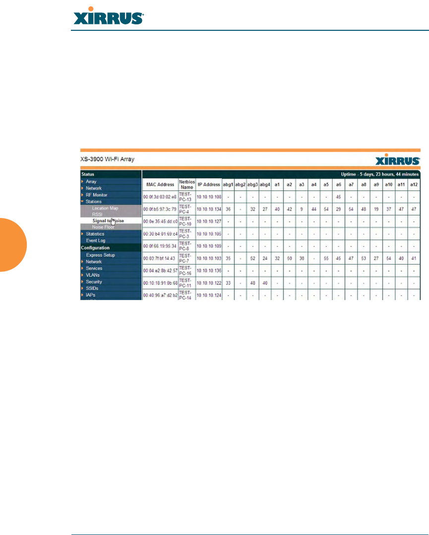
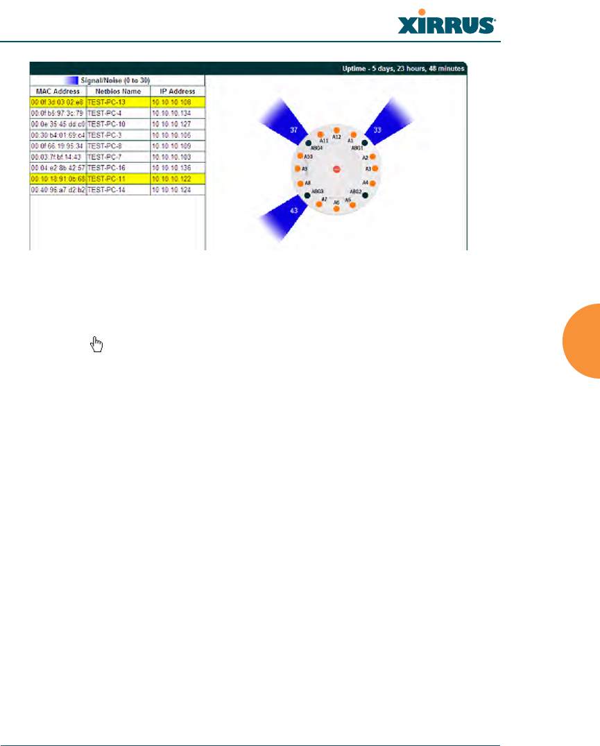
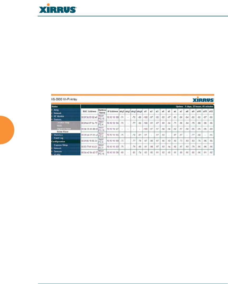
Signal-to-Noise Ratio (SNR)
For each station that is associated to the Array, the Signal-to-Noise Ratio (SNR)
window shows the station’s SNR value as measured by each IAP. In other words,
the window shows the SNR of the station’s signal at each IAP radio. The signal-
to-noise ratio can be very useful for determining the cause of poor performance at
a station. A low value means that action may need to be taken to reduce sources of
noise in the environment and/or improve the signal from the station.
Figure 74. Station Signal-to-Noise Ratio Values
You may choose to display Unassociated Stations as well with a checkbox at the
bottom of the window.
By default, the SNR is displayed numerically. (Figure 74) You may display
the relative value using color if you select Colorize Intensity, with the highest
SNR indicated by the most intense color. (Figure 75) If you select Graph, then
the SNR is shown on a representation of the Array, either colorized or numerically
based on your selection. The stations are listed to the left of the Array—click on a
station to show its SNR values on the Array.
Wi-Fi Array
Viewing Status on the Wi-Fi Array 121
Figure 75. Station SNR Values—Colorized Graphical View
In either graphical or tabular view, you may sort the rows based on any column
that has an active column header, indicated when the mouse pointer changes to
the hand icon . Click on the Refresh button to refresh the station list, or click in
the Auto Refresh check box to instruct the Array to refresh this window
automatically.
See Also
Station Status Windows
RF Monitor Windows
Wi-Fi Array
122 Viewing Status on the Wi-Fi Array
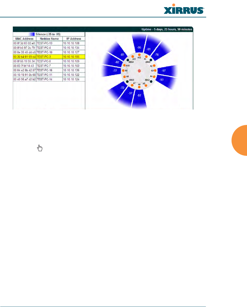
Noise Floor
For each station that is associated to the Array, the Noise Floor window shows
the ambient noise affecting a station’s signal as measured by each IAP. The noise
floor is the RSSI value when the station is not transmitting, sometimes called a
Silence value. In other words, the window shows the noise floor of the station’s
signal at each IAP radio. The noise floor value can be very useful for
characterizing the environment of a station to determine the cause of poor
performance. A relatively high value means that action may need to be taken to
reduce sources of noise in the environment.
Figure 76. Station Noise Floor Values
You may choose to display Unassociated Stations as well with a checkbox at the
bottom of the window.
By default, the noise floor is displayed numerically. (Figure 76) You may display
the relative value using color if you select Colorize Intensity, with the highest
noise indicated by the most intense color. If you select Graph, then the ambient
noise is shown on a representation of the Array, either colorized or numerically
based on your selection.(Figure 77) The stations are listed to the left of the
Array—click on a station to show its values on the Array.
Wi-Fi Array
Viewing Status on the Wi-Fi Array 123
Figure 77. Station Noise Floor Values—Colorized Graphical View
In either graphical or tabular view, you may sort the rows based on any column
that has an active column header, indicated when the mouse pointer changes to
the hand icon . Click on the Refresh button to refresh the station list, or click in
the Auto Refresh check box to instruct the Array to refresh this window
automatically.
See Also
Station Status Windows
RF Monitor Windows

Wi-Fi Array
124 Viewing Status on the Wi-Fi Array
Statistics Windows
The following Array Statistics windows are available:
zIAP Statistics Summary—provides an overview of the statistical data
associated with all IAPs. Expands to show links for displaying detailed
statistics for individual IAPs.
zPer-IAP Statistics—provides detailed statistics for an individual IAP.
zNetwork Statistics—displays statistical data associated with each
network (Ethernet) interface.
zVLAN Statistics—provides statistical data associated with your assigned
VLANs.
zWDS Statistics—provides statistical data for all WDS client and host
links.
zFilter Statistics—provides statistical data for all configured filters.
zStation Statistics—provides statistical data associated with each station.
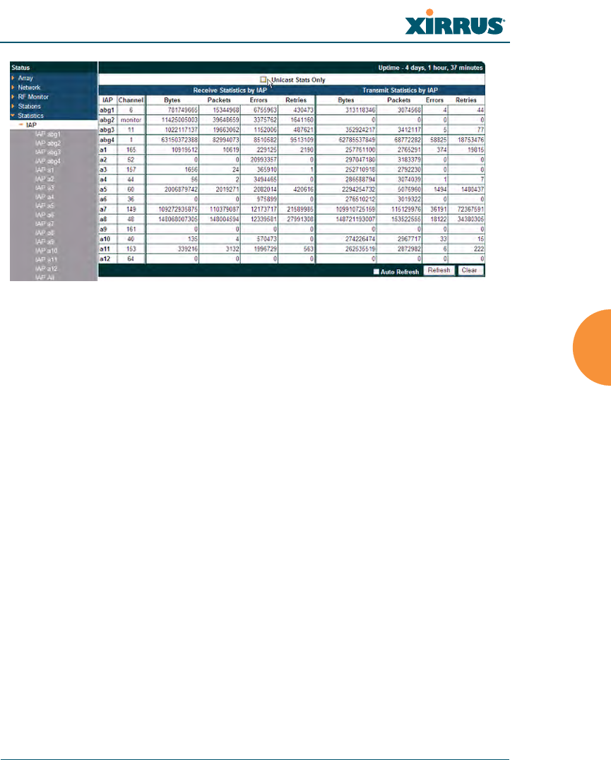
IAP Statistics Summary
This is a status only window that provides an overview of the statistical data
associated with all IAPs. It also shows the channel used by each IAP. For detailed
statistics for a specific IAP, see “Per-IAP Statistics” on page 125. Click the Unicast
Stats Only checkbox above the statistics to filter the results, or clear the checkbox
to show statistics for all wireless traffic.
You can Refresh the data (update the window with the latest information) or
Clear the data (reset all content to zero and begin counting again) at any time by
clicking on the appropriate button. You can also click in the Auto Refresh check
box to instruct the Array to refresh this window automatically.
Wi-Fi Array
Viewing Status on the Wi-Fi Array 125
Figure 78. IAP Statistics Summary Page
See Also
System Log Window
Global Settings (IAP)
Global Settings .11an
Global Settings .11bgn
IAPs
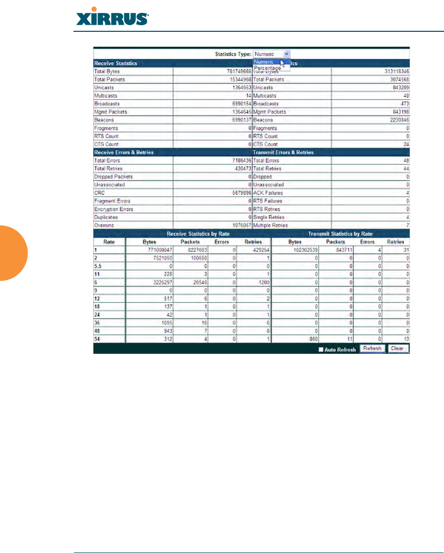
Per-IAP Statistics
This is a status only window that provides detailed statistics for the selected IAP.
If you click the link for IAP All in the left frame, each detailed statistic field will
show the sum of that statistic for all IAPs. For a summary of statistics for all IAPs,
see “IAP Statistics Summary” on page 124. Use the Statistics Type drop-down
field above the statistics to select the output format - Numeric for raw numbers,
or Percentage to express each statistic as a percentage of the total at the top of the
column.
Wi-Fi Array
126 Viewing Status on the Wi-Fi Array
Figure 79. Individual IAP Statistics Page (for IAP abg1)
You can Refresh the data (update the window with the latest information) or
Clear the data (reset all content to zero and begin counting again) at any time by
clicking on the appropriate button. You can also click in the Auto Refresh check
box to instruct the Array to refresh this window automatically.
See Also
System Log Window
Global Settings (IAP)
Global Settings .11an
Global Settings .11bgn
Wi-Fi Array
Viewing Status on the Wi-Fi Array 127
IAPs
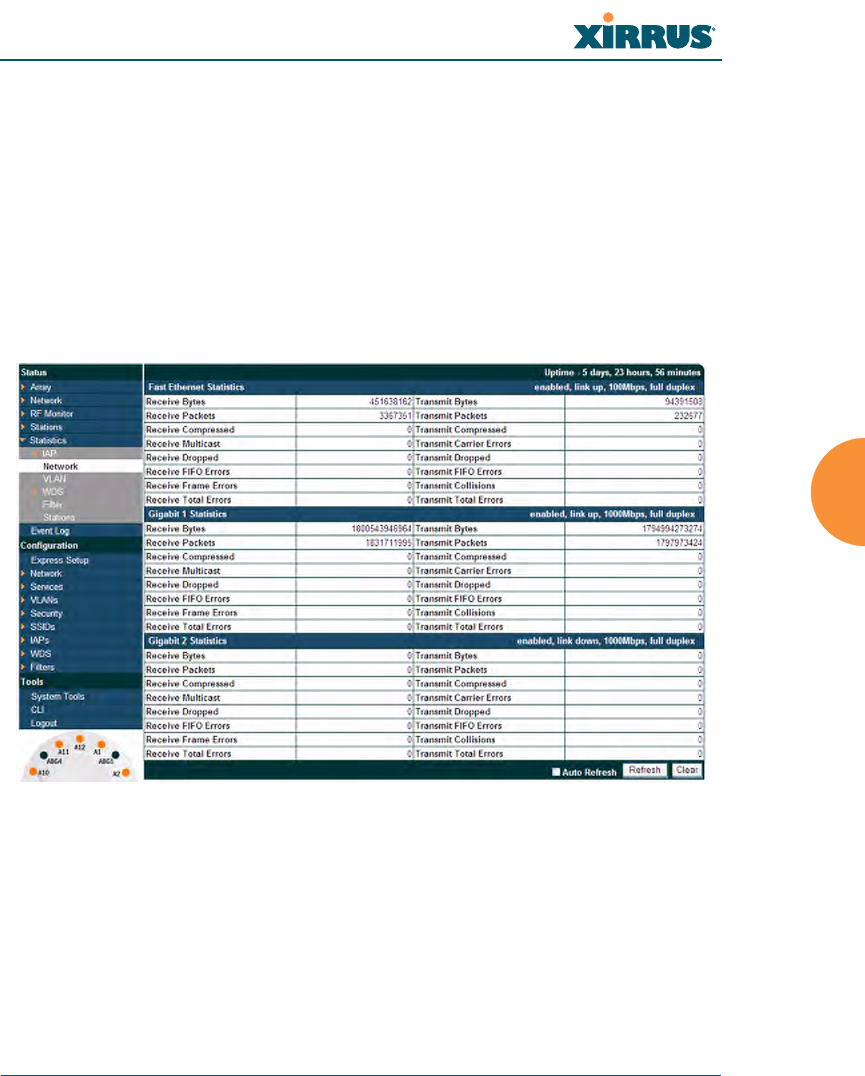
Network Statistics
This is a status only window that allows you to review statistical data associated
with each network (Ethernet) interface and its activity. You can Refresh the data
(update the window with the latest information) or Clear the data (reset all
content to zero and begin counting again) at any time by clicking on the
appropriate button. You can also click in the Auto Refresh check box to instruct
the Array to refresh this window automatically. If you are experiencing problems
on the Array, you may also want to print this window for your records.
Figure 80. Network Statistics
See Also
DHCP Server
DNS Settings
Network
Network Interfaces
Wi-Fi Array
128 Viewing Status on the Wi-Fi Array
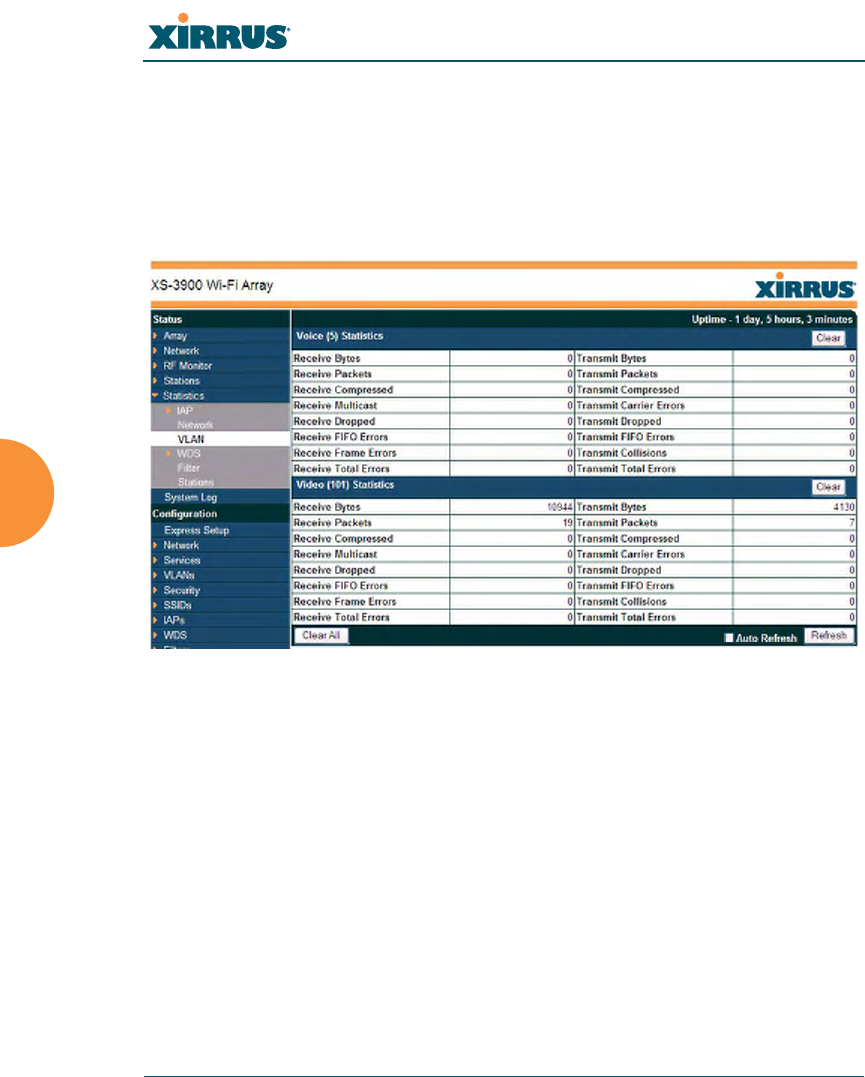
VLAN Statistics
This is a status only window that allows you to review statistical data associated
with your assigned VLANs. You can refresh the information that is displayed on
this page at any time by clicking on the Refresh button, or select the Auto Refresh
option for this window to refresh automatically. The Clear All button at the lower
left allows you to clear (zero out) all VLAN statistics.
Figure 81. VLAN Statistics
See Also
VLAN Management
VLANs
Wi-Fi Array
Viewing Status on the Wi-Fi Array 129
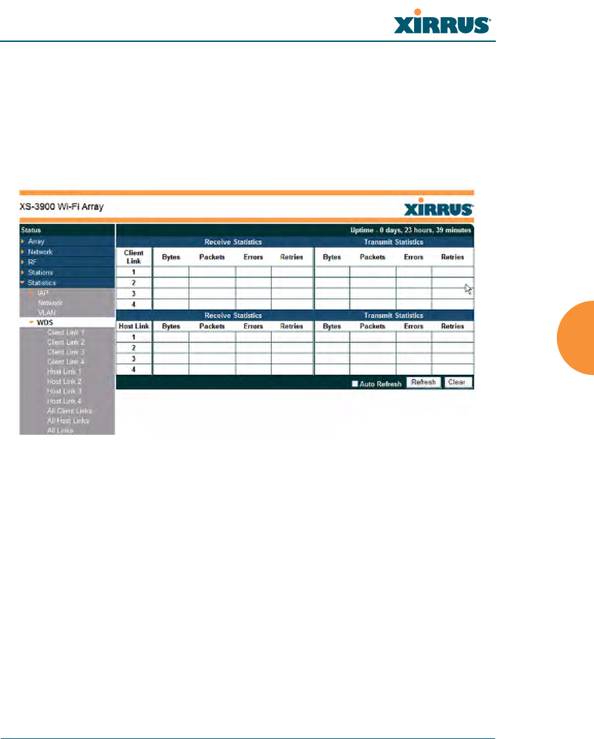
WDS Statistics
The main WDS Statistics window provides statistical data for all WDS client and
host links. To access data about a specific WDS client or host link, simply click on
the desired link in the left frame to access the appropriate window. You can also
select to view a sum of the statistics for all client links, all host links, or all links
(both client and host links).
Figure 82. WDS Statistics
See Also
SSID Management
WDS
Wi-Fi Array
130 Viewing Status on the Wi-Fi Array
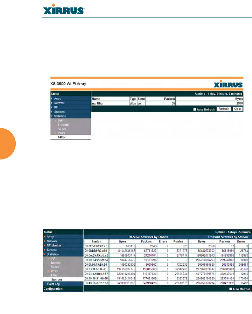
Filter Statistics
The Filter Statistics window provides statistical data for all configured filters. The
name, state (enabled—on or off), and type (allow or deny) of each filter is shown.
For enabled filters, this window shows the number of packets and bytes that met
the filter criteria. Click on a column header to sort the rows based on that column.
Click on a filter name to edit the filter settings.
Figure 83. Filter Statistics
See Also
Filters
Station Statistics
This status-only window provides an overview of statistical data for all stations.
Stations are listed by MAC address, and Receive and Transmit statistics are
summarized for each. For detailed statistics for a specific station, click the desired
MAC address in the Station column and see “Per-Station Statistics” on page 131.
Figure 84. Station Statistics
Wi-Fi Array
Viewing Status on the Wi-Fi Array 131
You can Refresh the data (update the window with the latest information) at any
time by clicking on the appropriate button. You can also click in the Auto Refresh
check box to instruct the Array to refresh this window automatically.
Note that you can clear the data for an individual station (see below), but you
cannot clear the data for all stations using this window.
See Also
Per-Station Statistics
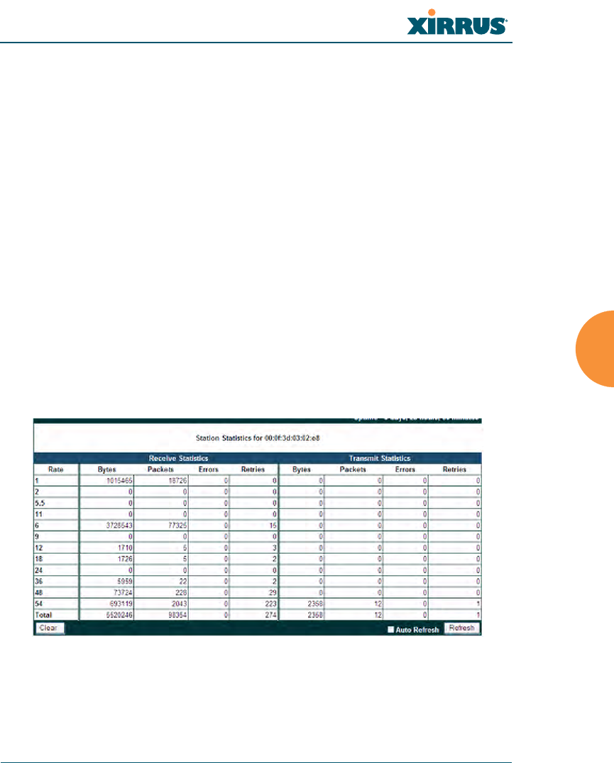
Per-Station Statistics
This window provides detailed statistics for the selected station. Receive and
Transmit statistics are listed by Rate—this is the data rate in Mbps. For a
summary of statistics for all stations, see “Station Statistics” on page 130.
You can Refresh the data (update the window with the latest information) or
Clear the data (reset all content to zero and begin counting again) at any time by
clicking on the appropriate button. You can also click in the Auto Refresh check
box to instruct the Array to refresh this window automatically.
Figure 85. Individual Station Statistics Page
See Also
Station Statistics
Wi-Fi Array
132 Viewing Status on the Wi-Fi Array
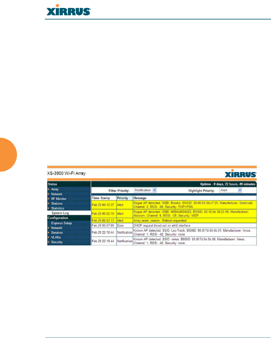
System Log Window
This is a status only window that allows you to review the system log, where
system alerts and messages are displayed. Although there are no configuration
options available in this window, you do have the usual choice of deciding how
the event messages are sorted by clicking in the column header for the desired
field (Time Stamp, Priority, or Message).
zTime Stamp—sorts the list based on the time the event occurred.
zPriority—sorts the list based on the priority assigned to the message.
zMessage—sorts the list based on the message category
The displayed messages may be filtered by using the Filter Priority option, which
allows control of the minimum priority level displayed. For example, you may
choose (under Services >System Log) to log messages at or above the Debug
level but use Filter Priority to display only messages at the Information level and
above.
Figure 86. System Log (modified for clarity)
Use the Highlight Priority field if you wish to highlight messages at the selected
priority level. Click on the Refresh button to refresh the message list, or click on
the Clear Log button to delete all messages. You can also click in the Auto
Refresh check box to instruct the Array to refresh this window automatically.

Wi-Fi Array
Configuring the Wi-Fi Array 133
Configuring the Wi-Fi Array
The following topics include procedures for configuring the Array using the
product’s embedded Web Management Interface (WMI). Procedures have been
organized into functional areas that reflect the flow and content of the WMI.
The following WMI windows allow you to establish configuration parameters for
your Array, and include:
z“Express Setup” on page 134
z“Network” on page 140
z“Services” on page 151
z“VLANs” on page 161
z“Security” on page 164
z“SSIDs” on page 184
z“Groups” on page 196
z“IAPs” on page 202
z“WDS” on page 229
z“Filters” on page 233
After making changes to the configuration settings of an Array you must click on
the Save button at the bottom of the configuration window, otherwise the changes
you make will not be applied the next time the Array is rebooted. Click the Apply
button if you want the changes applied to the current configuration, without
making them permanent.
This chapter only discusses using the configuration windows on the Array. To
view status or use system tools on the Array, please see:
z“Viewing Status on the Wi-Fi Array” on page 91
z“Using Tools on the Wi-Fi Array” on page 239
Wi-Fi Array
134 Configuring the Wi-Fi Array
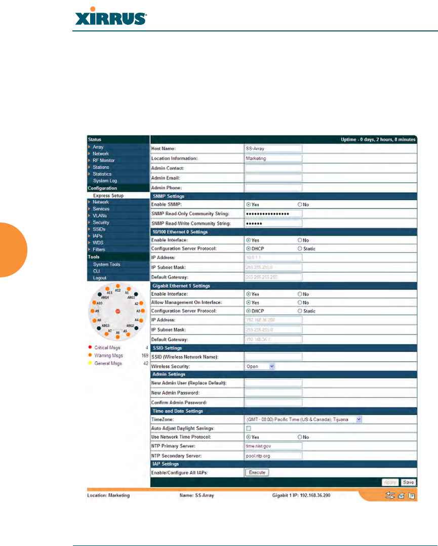
Express Setup
The Express Setup procedure allows you to establish global configuration settings
that will enable basic Array functionality. Any changes you make in this window
will affect all radios. When finished, click on the Apply button to apply the new
settings to this session, or click Save to apply your changes and make them
permanent.
Figure 87. WMI: Express Setup

Wi-Fi Array
Configuring the Wi-Fi Array 135
Procedure for Performing an Express Setup
1. Host Name: Specify a unique host name for this Array. The host name is
used to identify the Array on the network. Use a name that will be
meaningful within your network environment, up to 64 alphanumeric
characters. The default is Xirrus-WiFi-Array.
2. Location Information: Enter a brief but meaningful description that
accurately defines the physical location of the Array. In an environment
where multiple units are installed, clear definitions for their locations are
important if you want to identify a specific unit.
3. Admin Contact: Enter the name and contact information of the person
who is responsible for administering the Array at the designated location.
4. Admin Email: Enter the email address of the admin contact you entered
in Step 3.
5. Admin Phone: Enter the telephone number of the admin contact you
entered in Step 3.
6. Configure SNMP: Select whether to Enable SNMP on the Array, and set
the SNMP community strings. The factory default value for the SNMP
Read-Only Community String is xirrus_read_only. The factory default
value for the SNMP Read-Write Community String is xirrus. If you are
using the Xirrus Management System (XMS), the read-write string must
match the string used by XMS. XMS also uses the default value xirrus.
7. Configure the 10/100 Ethernet 0 (10/100 Mb) and Gigabit Ethernet 1
network interface settings. Note that the and Gigabit Ethernet 2 port is
not configured on this page. If you need to make changes to Gigabit 2,
please see “Network Interfaces” on page 141.
The fields for each of these interfaces are similar, and include:
a. Enable Interface: Choose Yes to enable this network interface, or
choose No to disable the interface.
b. Allow Management on Interface: This option is available only on the
Gigabit 1 and Gigabit 2 interfaces—the 10/100 Ethernet port is also
known as the Management Port, and management is always enabled

Wi-Fi Array
136 Configuring the Wi-Fi Array
on this port. Choose Yes to allow management of the Array via this
Gigabit interface, or choose No to deny all management privileges for
this interface.
c. Configuration Server Protocol: Choose DHCP to instruct the Array
to use DHCP to assign IP addresses to the Array’s Ethernet interfaces,
or choose Static if you intend to enter IP addresses manually. If you
choose the Static IP option, you must enter the following information:
•IP Address: Enter a valid IP address for this Array. To use a
remote connection (Web, SNMP, or SSH), a valid IP address must
be used.
•IP Subnet Mask: Enter a valid IP address for the subnet mask
(the default is 255.255.255.0). The subnet mask defines the
number of IP addresses that are available on the routed subnet
where the Array is located.
•Default Gateway: Enter a valid IP address for the default
gateway. This is the IP address of the router that the Array uses
to forward data to other networks.
8. SSID Settings: This section specifies the wireless network name and
security settings.
a. The SSID (Wireless Network Name) is a unique name that identifies
a wireless network (SSID stands for Service Set Identifier). All devices
attempting to connect to a specific WLAN must use the same SSID.
The default SSID is xirrus. Entering a value in this field will replace
the default SSID with the new name.
For additional information about SSIDs, go to the Multiple SSIDs
section of “Frequently Asked Questions” on page 334.
b. Wireless Security: Select the desired wireless security scheme (Open,
WEP or WPA). Make your selection from the choices available in the
pull-down list.
•Open—This option offers no data encryption and is not
recommended, though you might choose this option if clients are

Wi-Fi Array
Configuring the Wi-Fi Array 137
required to use a VPN connection through a secure SSH utility,
like PuTTy.
•WEP (Wired Equivalent Privacy)—An optional IEEE 802.11
function that offers frame transmission privacy similar to a wired
network. WEP generates secret shared encryption keys that both
source and destination stations can use to alter frame bits to
avoid disclosure to eavesdroppers.
•WPA (Wi-Fi Protected Access)—A Wi-Fi Alliance standard that
contains a subset of the IEEE 802.11i standard, using TKIP or AES
as an encryption method and 802.1x for authentication. WPA is
the stronger of the two wireless security schemes.
•WPA2 (Wi-Fi Protected Access 2)—WPA2 is the follow-on
security method to WPA for wireless networks and provides
stronger data protection and network access control. It offers
Enterprise and consumer Wi-Fi users with a high level of
assurance that only authorized users can access their wireless
networks. Like WPA, WPA2 is designed to secure all versions of
802.11 devices, including 802.11a, 802.11b, 802.11g, and 802.11n,
multi-band and multi-mode.
•WPA-Both (WPA and WPA2)—This option makes use of both
WPA and WPA2.
For more information about security, including a full review of all
security options and settings, go to “Understanding Security” on
page 165.
c. Wireless Key/Passphrase: Depending on the wireless security
scheme you selected, enter a unique WEP key or WPA passphrase.
d. Confirm Key/Passphrase: If you entered a WEP key or WPA
passphrase, confirm it here.
9. Admin Settings: This section allows you to change the default admin
username and password for the Array.
a. New Admin User (Replace Default): Enter the name of a new
administrator user account. The new administrator will have read/