Cambium Networks XN8 Wireless LAN Array User Manual XN PDF
Xirrus, Inc. Wireless LAN Array XN PDF
Contents
Users Manual pt1of5

June 10, 2008

All rights reserved. This document may not be reproduced or
disclosed in whole or in part by any means without the written
consent of Xirrus, Inc.
Wi-Fi Array
XN16, XN8, XN4
™

Trademarks
is a registered trademark of Xirrus, Inc. All other trademarks and brand
names are marks of their respective holders.
Notices
FCC Notice
This equipment has been tested and found to comply with the limits for a Class B
digital device, pursuant to part 15 of the FCC Rules. These limits are designed to
provide reasonable protection against harmful interference in a residential
installation. This equipment generates, uses, and can radiate radio frequency
energy and if not installed and used in accordance with the instructions, may
cause harmful interference to radio communications. However, there is no
guarantee that interference will not occur in a particular installation.
If this equipment does cause harmful interference to radio or television reception,
which can be determined by turning the equipment off and on, you are
encouraged to try to correct the interference by one or more of the following
measures:
zReorient or relocate the receiving antenna.
zIncrease the separation between the equipment and the receiver.
zConsult the dealer or an experienced wireless technician for help.
Use of a shielded twisted pair (STP) cable must be used for all Ethernet
connections in order to comply with EMC requirements.
RF Radiation Hazard Warning
To ensure compliance with FCC RF exposure requirements, this device must be
installed in a location where the antennas of the device will have a minimum
distance of at least 25 cm (9.84 inches) from all persons. Using higher gain
antennas and types of antennas not certified for use with this product is not
allowed. The device shall not be co-located with another transmitter.
Non-Modification Statement
Unauthorized changes or modifications to the device are not permitted. Use only
the supplied internal antenna, or external antennas supplied by the manufacturer.
Modifications to the device will void the warranty and may violate FCC
regulations. Please go to the Xirrus Web site for a list of all approved antennas.
Indoor Use
This product has been designed for indoor use. Operation of channels in the
5150MHz to 5250MHz band is permitted indoors only to reduce the potential for
harmful interference to co-channel mobile satellite systems.
Cable Runs for Power over Gigabit Ethernet (PoGE)
If using PoGE, the Array must be connected to PoGE networks without routing
cabling to the outside plant—this ensures that cabling is not exposed to lightning
strikes or possible cross over from high voltage.
Battery Warning
Caution! The Array contains a battery which is not to be replaced by the customer.
Danger of Explosion exists if the battery is incorrectly replaced. Replace only with
the same or equivalent type recommended by the manufacturer. Dispose of used
batteries according to the manufacturer's instructions.
Power Cord
If you will be using the Array with a power cord, you must use a UL-Approved
cord. Order the power cord from the Xirrus product list—Xirrus supplies only
UL-approved power cords.
Maximum Antenna Gain
Currently, the maximum antenna gain for external antennas is limited to 2.5dBi
for operation in the 5150MHz to 5250MHz and 5725MHz to 5825MHz bands. The
antenna gains must not exceed maximum EIRP limits set by the FCC / Industry
Canada.
High Power Radars
High power radars are allocated as primary users (meaning they have priority) in
the 5150MHz to 5250MHz and 5725 MHz to 5825MHz bands. These radars could
cause interference and/or damage to LELAN devices used in Canada.
Industry Canada Notice and Marking
This Class A digital apparatus complies with Canadian ICES-003.
Cet appareil numérique de la classe A est conforme à la norme NMB-003 du Canada.
The term “IC:” before the radio certification number only signifies that Industry
Canada technical specifications were met.
To reduce potential radio interference to other users, the antenna type and its gain
should be so chosen that the equivalent isotropically radiated power (EIRP) is not
more than that required for successful communication.
EU Directive 1999/5/EC Compliance Information
This section contains compliance information for the Xirrus Wi-Fi Array family of
products, which includes the XN16, XN8, and XN4. The compliance information
contained in this section is relevant to the European Union and other countries
that have implemented the EU Directive 1999/5/EC.
Declaration of Conformity
Cesky [Czech] Toto zahzeni je v souladu se základnimi požadavky a
ostatnimi odpovidajcimi ustano veni mi Směrnice
1999/5/EC.
Dansk [Danish] Dette udstyr er i overensstemmelse med de
væsentlige krav og andre relevante bestemmelser i
Direktiv 1999/5/EF.
Deutsch [German] Dieses Gerat entspricht den grundlegenden
Anforderungen und den weiteren entsprechenden
Vorgaben der Richtinie 1999/5/EU.
Eesti [Estonian] See seande vastab direktiivi 1999/5/EU olulistele
nöuetele ja teistele as jakohastele sätetele.
English This equipment is in compliance with the essential
requirements and other relevant provisions of
Directive 1999/5/EC.
Español [Spain] Este equipo cump le con los requisitos esenciales asi
como con otras disposiciones de la Directiva 1999/5/
CE.
Ελληνυκη [Greek] Αυτόζ ο εξοπλτσμόζ είναι σε συμμόρφωση με τιζ
ουσιώδειζ απαιτήσειζ και ύλλεζ σχετικέζ διατάξειζ τηζ
Οδηγιαζ 1999/5/EC.
Français [French] Cet appareil est conforme aux exigences essentielles
et aux autres dispositions pertinentes de la Directive
1999/5/EC.
ĺslenska [Icelandic] Þetta tæki er samkvæmt grunnkröfum og öðrum
viðeigandi ákvæðum Tilskipunar 1999/5/EC.
Italiano [Italian] Questo apparato é conforme ai requisiti essenziali ed
agli altri principi sanciti dalla Direttiva 1999/5/CE.
Latviski [Latvian] Šī iekārta atbilst Direktīvas 1999/5/EK būtiskajā
prasībām un citiem ar to saistītajiem noteikumiem.
Lietuvių [Lithuanian] Šis įrenginys tenkina 1995/5/EB Direktyvos
esminius reikalavimus ir kitas šios direktyvos
nuostatas.
Nederlands [Dutch] Dit apparant voldoet aan de essentiele eisen en
andere van toepassing zijnde bepalingen van de
Richtlijn 1995/5/EC.
Malti [Maltese] Dan l-apparant huwa konformi mal-htigiet essenzjali
u l-provedimenti l-ohra rilevanti tad-Direttiva 1999/
5/EC.
Margyar [Hungarian] Ez a készülék teljesiti az alapvetö követelményeket
és más 1999/5/EK irányelvben meghatározott
vonatkozó rendelkezéseket.
Norsk [Norwegian] Dette utstyret er i samsvar med de grunnleggende
krav og andre relevante bestemmelser i EU-direktiv
1999/5/EF.
Polski [Polish] Urządzenie jest zgodne z ogólnymi wymaganiami
oraz sczególnymi mi warunkami określony mi
Dyrektywą. UE:1999/5/EC.
Portuguès [Portugese] Este equipamento está em conformidade com os
requisitos essenciais e outras provisões relevantes da
Directiva 1999/5/EC.
Slovensko [Slovenian] Ta naprava je skladna z bistvenimi zahtevami in
ostalimi relevantnimi popoji Direktive 1999/5/EC.
Slovensky [Slovak] Toto zariadenie je v zhode so základnými
požadavkami a inými prislušnými nariadeniami
direktiv: 1999/5/EC.

Assessment Criteria
The following standards were applied during the assessment of the product
against the requirements of the Directive 1999/5/EC:
zRadio: EN 301 893 and EN 300 328 (if applicable)
zEMC: EN 301 489-1 and EN 301 489-17
zSafety: EN 50371 to EN 50385 and EN 60601
CE Marking
For the Xirrus Wi-Fi Array (XN16, XN8, XN4), the CE mark and Class-2 identifier
opposite are affixed to the equipment and its packaging:
Suomi [Finnish] Tämä laite täyttää direktiivin 1999/5//EY olennaiset
vaatimukset ja on siinä asetettujen muiden laitetta
koskevien määräysten mukainen.
Svenska [Swedish] Denna utrustning är i överensstämmelse med de
väsentliga kraven och andra relevanta bestämmelser
i Direktiv 1999/5/EC.

WEEE Compliance
zNatural resources were used in the production
of this equipment.
zThis equipment may contain hazardous
substances that could impact the health of the
environment.
zIn order to avoid harm to the environment and
consumption of natural resources, we
encourage you to use appropriate take-back
systems when disposing of this equipment.
zThe appropriate take-back systems will reuse
or recycle most of the materials of this
equipment in a way that will not harm the
environment.
zThe crossed-out wheeled bin symbol (in
accordance with European Standard EN 50419)
invites you to use those take-back systems and
advises you not to combine the material with
refuse destined for a land fill.
zIf you need more information on collection, re-
use and recycling systems, please contact your
local or regional waste administration.
zPlease contact Xirrus for specific information
on the environmental performance of our

National Restrictions
In the majority of the EU and other European countries, the 2.4 GHz and 5 GHz
bands have been made available for the use of Wireless LANs. The following table
provides an overview of the regulatory requirements in general that are
applicable for the 2.4 GHz and 5 GHz bands.
*Dynamic frequency selection and Transmit Power Control is required in these
frequency bands.
**France is indoor use only in the upper end of the band.
The requirements for any country may change at any time. Xirrus recommends
that you check with local authorities for the current status of their national
regulations for both 2.4 GHz and 5 GHz wireless LANs.
The following countries have additional requirements or restrictions than those
listed in the above table:
Belgium
The Belgian Institute for Postal Services and Telecommunications (BIPT) must
be notified of any outdoor wireless link having a range exceeding 300 meters.
Xirrus recommends checking at www.bipt.be for more details.
Draadloze verbindingen voor buitengebruik en met een reikwijdte van meer dan 300
meter dienen aangemeld te worden bij het Belgisch Instituut voor postdiensten en
telecommunicatie (BIPT). Zie www.bipt.be voor meer gegevens.
Les liasons sans fil pour une utilisation en extérieur d’une distance supérieure à 300
mèters doivent être notifiées à l’Institut Belge des services Postaux et des
Télécommunications (IBPT). Visitez www.bipt.be pour de plus amples détails.
Frequency
Band (MHz) Max Power Level
(EIRP) (mW) Indoor Outdoor
2400–2483.5 100 X X**
5150–5250* 200 X N/A
5470–5725* 1000 X X
Greece
A license from EETT is required for the outdoor operation in the 5470 MHz to
5725 MHz band. Xirrus recommends checking www.eett.gr for more details.
Η δη ιουργβάικτ ωνεξωτερικο ρουστη ζ νησυ νοτ των 5470–5725 ΜΗz ε ιτρ ετάιωνο
ετάά όάδειά της ΕΕΤΤ, ου ορηγεβτάι στερά ά ό σ φωνη γν η του ΓΕΕΘΑ. ερισσότερες
λε τομ ρειεωστο www.eett.gr
Italy
This product meets the National Radio Interface and the requirements
specified in the National Frequency Allocation Table for Italy. Unless this
wireless LAN product is operating within the boundaries of the owner’s
property, its use requires a “general authorization.” Please check with
www.communicazioni.it/it/ for more details.
Questo prodotto é conforme alla specifiche di Interfaccia Radio Nazionali e rispetta il
Piano Nazionale di ripartizione delle frequenze in Italia. Se non viene installato
all’interno del proprio fondo, l’utilizzo di prodotti wireless LAN richiede una
“autorizzazione Generale.” Consultare www.communicazioni.it/it/ per maggiori
dettagli.
Norway, Switzerland and Liechtenstein
Although Norway, Switzerland and Liechtenstein are not EU member states,
the EU Directive 1999/5/EC has also been implemented in those countries.
Calculating the Maximum Output Power
The regulatory limits for maximum output power are specified in EIRP (radiated
power). The EIRP level of a device can be calculated by adding the gain of the
antenna used (specified in dBi) to the output power available at the connector
(specified in dBm).
Antennas
The Xirrus Wi-Fi Array employs integrated antennas that cannot be removed and
which are not user accessible. Nevertheless, as regulatory limits are not the same
throughout the EU, users may need to adjust the conducted power setting for the
radio to meet the EIRP limits applicable in their country or region. Adjustments
can be made from the product’s management interface—either Web Management
Interface (WMI) or Command Line Interface (CLI).
Operating Frequency
The operating frequency in a wireless LAN is determined by the access point. As
such, it is important that the access point is correctly configured to meet the local
regulations. See National Restrictions in this section for more information.
If you still have questions regarding the compliance of Xirrus products or you
cannot find the information you are looking for, please contact us at:
Xirrus, Inc.
370 North Westlake Blvd, Suite 200
Westlake Village, CA 91362
USA
Tel: 1.805.497.0955
Fax: 1.805.449.1180
www.xirrus.com
Safety Warnings
Translated safety warnings appear on the following page.
!Safety Warnings
Read all user documentation before powering this device. All Xirrus
interconnected equipment should be contained indoors. This product is
not suitable for outdoor operation. Please verify the integrity of the
system ground prior to installing Xirrus equipment. Additionally,
verify that the ambient operating temperature does not exceed 50°C.
!Explosive Device Proximity Warning
Do not operate the XN16/XN8/XN4 unit near unshielded blasting caps
or in an explosive environment unless the device has been modified to
be especially qualified for such use.
!Lightning Activity Warning
Do not work on the XN16/XN8/XN4 or connect or disconnect cables
during periods of lightning activity.
!Circuit Breaker Warning
The XN16/XN8/XN4 relies on the building’s installation for over
current protection. Ensure that a fuse or circuit breaker no larger than
120 VAC, 15A (U.S.) or 240 VAC, 10A (International) is used on all
current-carrying conductors.
Translated Safety Warnings
Avertissements de Sécurité
!Sécurité
Lisez l'ensemble de la documentation utilisateur avant de mettre cet
appareil sous tension. Tous les équipements Xirrus interconnectés
doivent être installés en intérieur. Ce produit n'est pas conçu pour être
utilisé en extérieur. Veuillez vérifier l'intégrité de la terre du système
avant d'installer des équipements Xirrus. Vérifiez également que la
température de fonctionnement ambiante n'excède pas 50°C.
!Proximité d'appareils explosifs
N'utilisez pas l'unité XN16/XN8/XN4 à proximité d'amorces non
blindées ou dans un environnement explosif, à moins que l'appareil
n'ait été spécifiquement modifié pour un tel usage.
!Foudre
N'utilisez pas l'unité XN16/XN8/XN4 et ne branchez pas ou ne
débranchez pas de câbles en cas de foudre.
!Disjoncteur
L'unité XN16/XN8/XN4 dépend de l'installation du bâtiment pour ce
qui est de la protection contre les surintensités. Assurez-vous qu'un
fusible ou qu'un disjoncteur de 120 Vca, 15 A (États-Unis) ou de 240
Vca, 10 A (International) maximum est utilisé sur tous les conducteurs
de courant.
Software Warranty and License Agreement
THIS SOFTWARE LICENSE AGREEMENT (THE “AGREEMENT”) IS A LEGAL
AGREEMENT BETWEEN YOU (“CUSTOMER”) AND LICENSOR (AS DEFINED
BELOW) AND GOVERNS THE USE OF THE SOFTWARE INSTALLED ON THE
PRODUCT (AS DEFINED BELOW). IF YOU ARE AN EMPLOYEE OR AGENT
OF CUSTOMER, YOU HEREBY REPRESENT AND WARRANT TO LICENSOR
THAT YOU HAVE THE POWER AND AUTHORITY TO ACCEPT AND TO
BIND CUSTOMER TO THE TERMS AND CONDITIONS OF THIS AGREEMENT
(INCLUDING ANY THIRD PARTY TERMS SET FORTH HEREIN). IF YOU DO
NOT AGREE TO ALL OF THE TERMS OF THIS AGREEMENT RETURN THE
PRODUCT AND ALL ACCOMPANYING MATERIALS (INCLUDING ALL
DOCUMENTATION) TO THE RELEVANT VENDOR FOR A FULL REFUND OF
THE PURCHASE PRICE THEREFOR.
CUSTOMER UNDERSTANDS AND AGREES THAT USE OF THE SOFTWARE
SHALL BE DEEMED AN AGREEMENT TO THE TERMS AND CONDITIONS
GOVERNING SUCH SOFTWARE AND THAT CUSTOMER IS BOUND BY AND
BECOMES A PARTY TO THIS AGREEMENT.
1. Definitions
1.1 “Documentation” means the user manuals and all other all
documentation, instructions or other similar materials accompanying the
Software covering the installation, application, and use thereof.
1.2 “Licensor” means XIRRUS and its suppliers.
1.3 “Product” means a multi-radio access point containing four or more
distinct radios capable of simultaneous operation on four or more non-
overlapping channels.
1.4 “Software” means, collectively, each of the application and embedded
software programs delivered to Customer in connection with this
Agreement. For purposes of this Agreement, the term Software shall be
deemed to include any and all Documentation and Updates provided
with or for the Software.
1.5 “Updates” means any bug-fix, maintenance or version release to the
Software that may be provided to Customer from Licensor pursuant to
this Agreement or pursuant to any separate maintenance and support
agreement entered into by and between Licensor and Customer.
2. Grant of Rights
2.1 Software. Subject to the terms and conditions of this Agreement, Licensor
hereby grants to Customer a perpetual, non-exclusive, non-
sublicenseable, non-transferable right and license to use the Software
solely as installed on the Product in accordance with the accompanying
Documentation and for no other purpose.
2.2 Ownership. The license granted under Sections 2.1 above with respect to
the Software does not constitute a transfer or sale of Licensor's or its
suppliers' ownership interest in or to the Software, which is solely
licensed to Customer. The Software is protected by both national and
international intellectual property laws and treaties. Except for the
express licenses granted to the Software, Licensor and its suppliers retain
all rights, title and interest in and to the Software, including (i) any and all
trade secrets, copyrights, patents and other proprietary rights therein or
thereto or (ii) any Marks (as defined in Section 2.3 below) used in
connection therewith. In no event shall Customer remove, efface or
otherwise obscure any Marks contained on or in the Software. All rights
not expressly granted herein are reserved by Licensor.
2.3 Copies. Customer shall not make any copies of the Software but shall be
permitted to make a reasonable number of copies of the related
Documentation. Whenever Customer copies or reproduces all or any part
of the Documentation, Customer shall reproduce all and not efface any
titles, trademark symbols, copyright symbols and legends, and other
proprietary markings or similar indicia of origin (“Marks”) on or in the
Documentation.
2.4 Restrictions. Customer shall not itself, or through any parent, subsidiary,
affiliate, agent or other third party (i) sell, rent, lease, license or
sublicense, assign or otherwise transfer the Software, or any of
Customer's rights and obligations under this Agreement except as
expressly permitted herein; (ii) decompile, disassemble, or reverse
engineer the Software, in whole or in part, provided that in those
jurisdictions in which a total prohibition on any reverse engineering is
prohibited as a matter of law and such prohibition is not cured by the fact
that this Agreement is subject to the laws of the State of California,
Licensor agrees to grant Customer, upon Customer's written request to
Licensor, a limited reverse engineering license to permit interoperability
of the Software with other software or code used by Customer; (iii) allow
access to the Software by any user other than by Customer's employees
and contractors who are bound in writing to confidentiality and non-use
restrictions at least as protective as those set forth herein; (iv) except as
expressly set forth herein, write or develop any derivative software or
any other software program based upon the Software; or (v) use any
computer software or hardware which is designated to defeat any copy
protection or other use limiting device, including any device intended to
limit the number of users or devices accessing the Product.
3. Limited Warranty and Limitation of Liability
3.1 Limited Warranty & Exclusions. Licensor warrants that the Software will
perform in substantial accordance with the specifications therefor set
forth in the Documentation for a period of ninety [90] days after
Customer's acceptance of the terms of this Agreement with respect to the
Software (“Warranty Period”). If during the Warranty Period the
Software does not perform as warranted, Licensor shall, at its option,
correct the relevant Software giving rise to such breach of performance or
replace such Software free of charge. THE FOREGOING ARE
CUSTOMER'S SOLE AND EXCLUSIVE REMEDIES FOR BREACH OF
THE FOREGOING WARRANTY. THE WARRANTY SET FORTH
ABOVE IS MADE TO AND FOR THE BENEFIT OF CUSTOMER ONLY.
The warranty will apply only if (i) the Software has been used at all times
and in accordance with the instructions for use set forth in the
Documentation and this Agreement; (ii) no modification, alteration or
addition has been made to the Software by persons other than Licensor or
Licensor's authorized representative; and (iii) the Software or Product on
which the Software is installed has not been subject to any unusual
electrical charge.
3.2 DISCLAIMER. EXCEPT AS EXPRESSLY STATED IN THIS SECTION 3,
ALL ADDITIONAL CONDITIONS, REPRESENTATIONS, AND
WARRANTIES, WHETHER IMPLIED, STATUTORY OR OTHERWISE,
INCLUDING, WITHOUT LIMITATION, ANY IMPLIED WARRANTIES
OR CONDITIONS OF MERCHANTABILITY, FITNESS FOR A
PARTICULAR PURPOSE, SATISFACTORY QUALITY, ACCURACY,
AGAINST INFRINGEMENT OR ARISING FROM A COURSE OF
DEALING, USAGE, OR TRADE PRACTICE, ARE HEREBY
DISCLAIMED BY LICENSOR AND ITS SUPPLIERS. THIS DISCLAIMER
SHALL APPLY EVEN IF ANY EXPRESS WARRANTY AND LIMITED
REMEDY OFFERED BY LICENSOR FAILS OF ITS ESSENTIAL
PURPOSE. ALL WARRANTIES PROVIDED BY LICENSOR ARE
SUBJECT TO THE LIMITATIONS OF LIABILITY SET FORTH IN THIS
AGREEMENT.
3.3 HAZARDOUS APPLICATIONS. THE SOFTWARE IS NOT DESIGNED
OR INTENDED FOR USE IN HAZARDOUS ENVIRONMENTS
REQUIRING FAIL SAFE PERFORMANCE, SUCH AS IN THE
OPERATION OF A NUCLEAR FACILITY, AIRCRAFT NAVIGATION OR
COMMUNICATIONS SYSTEMS, AIR TRAFFIC CONTROLS OR OTHER
DEVICES OR SYSTEMS IN WHICH A MALFUNCTION OF THE
SOFTWARE WOULD RESULT IN FORESEEABLE RISK OF INJURY OR
DEATH TO THE OPERATOR OF THE DEVICE OR SYSTEM OR TO
OTHERS (“HAZARDOUS APPLICATIONS”). CUSTOMER ASSUMES
ANY AND ALL RISKS, INJURIES, LOSSES, CLAIMS AND ANY OTHER
LIABILITIES ARISING OUT OF THE USE OF THE SOFTWARE IN ANY
HAZARDOUS APPLICATIONS.
3.4 Limitation of Liability.
(a) TOTAL LIABILITY. NOTWITHSTANDING ANYTHING ELSE
HEREIN, ALL LIABILITY OF LICENSOR AND ITS SUPPLIERS
UNDER THIS AGREEMENT SHALL BE LIMITED TO THE
AMOUNT PAID BY CUSTOMER FOR THE RELEVANT
SOFTWARE, OR PORTION THEREOF, THAT GAVE RISE TO SUCH
LIABILITY OR ONE HUNDRED UNITED STATES DOLLARS
(US$100), WHICHEVER IS GREATER. THE LIABILITY OF
LICENSOR AND ITS SUPPLIERS UNDER THIS SECTION SHALL
BE CUMULATIVE AND NOT PER INCIDENT.
(b) DAMAGES. IN NO EVENT SHALL LICENSOR, ITS SUPPLIERS OR
THEIR RELEVANT SUBCONTRACTORS BE LIABLE FOR (A) ANY
INCIDENTAL, SPECIAL, PUNITIVE OR CONSEQUENTIAL
DAMAGES, LOST PROFITS OR LOST OR DAMAGED DATA, OR
ANY INDIRECT DAMAGES, WHETHER ARISING IN CONTRACT,
TORT (INCLUDING NEGLIGENCE AND STRICT LIABILITY) OR
OTHERWISE OR (B) ANY COSTS OR EXPENSES FOR THE
PROCUREMENT OF SUBSTITUTE GOODS OR SERVICES IN EACH
CASE, EVEN IF LICENSOR OR ITS SUPPLIERS HAVE BEEN
INFORMED OF THE POSSIBILITY OF SUCH DAMAGES.
3.5 Exclusions. SOME JURISDICTIONS DO NOT PERMIT THE
LIMITATIONS OF LIABILITY AND LIMITED WARRANTIES SET
FORTH UNDER THIS AGREEMENT. IN THE EVENT YOU ARE
LOCATED IN ANY SUCH JURISDICTION, THE FOREGOING
LIMITATIONS SHALL APPLY ONLY TO THE MAXIMUM EXTENT
PERMITTED IN SUCH JURISDICTIONS. IN NO EVENT SHALL
THE FOREGOING EXCLUSIONS AND LIMITATIONS ON
DAMAGES BE DEEMED TO APPLY TO ANY LIABILITY BASED
ON FRAUD, WILLFUL MISCONDUCT, GROSS NEGLIGENCE OR
PERSONAL INJURY OR DEATH.
4. Confidential Information
4.1 Generally. The Software (and its accompanying Documentation)
constitutes Licensor's and its suppliers' proprietary and confidential
information and contains valuable trade secrets of Licensor and its
suppliers (“Confidential Information”). Customer shall protect the
secrecy of the Confidential Information to the same extent it protects its
other valuable, proprietary and confidential information of a similar
nature but in no event shall Customer use less than reasonable care to
maintain the secrecy of the Confidential Information. Customer shall not
use the Confidential Information except to exercise its rights or perform
its obligations as set forth under this Agreement. Customer shall not
disclose such Confidential Information to any third party other than
subject to non-use and non-disclosure obligations at least as protective of
a party's right in such Confidential Information as those set forth herein.
4.2 Return of Materials. Customer agrees to (i) destroy all Confidential
Information (including deleting any and all copies contained on any of
Customer's Designated Hardware or the Product) within fifteen (15) days
of the date of termination of this Agreement or (ii) if requested by
Licensor, return, any Confidential Information to Licensor within thirty
(30) days of Licensor's written request.
5. Term and Termination
5.1 Term. Subject to Section 5.2 below, this Agreement will take effect on the
Effective Date and will remain in force until terminated in accordance
with this Agreement.
5.2 Termination Events. This Agreement may be terminated immediately
upon written notice by either party under any of the following
conditions:
(a) If the other party has failed to cure a breach of any material term or
condition under the Agreement within thirty (30) days after receipt of
notice from the other party; or
(b) Either party ceases to carry on business as a going concern, either
party becomes the object of the institution of voluntary or
involuntary proceedings in bankruptcy or liquidation, which
proceeding is not dismissed within ninety (90) days, or a receiver is
appointed with respect to a substantial part of its assets.
5.3 Effect of Termination.
(a) Upon termination of this Agreement, in whole or in part, Customer
shall pay Licensor for all amounts owed up to the effective date of
termination. Termination of this Agreement shall not constitute a
waiver for any amounts due.
(b) The following Sections shall survive the termination of this
Agreement for any reason: Sections 1, 2.2, 2.4, 3, 4, 5.3, and 6.
(c) No later than thirty (30) days after the date of termination of this
Agreement by Licensor, Customer shall upon Licensor's instructions
either return the Software and all copies thereof; all Documentation
relating thereto in its possession that is in tangible form or destroy the
same (including any copies thereof contained on Customer's
Designated Hardware). Customer shall furnish Licensor with a
certificate signed by an executive officer of Customer verifying that
the same has been done.
6. Miscellaneous
If Customer is a corporation, partnership or similar entity, then the license to
the Software and Documentation that is granted under this Agreement is
expressly conditioned upon and Customer represents and warrants to
Licensor that the person accepting the terms of this Agreement is authorized
to bind such entity to the terms and conditions herein. If any provision of this
Agreement is held to be invalid or unenforceable, it will be enforced to the
extent permissible and the remainder of this Agreement will remain in full
force and effect. During the course of use of the Software, Licensor may
collect information on your use thereof; you hereby authorize Licensor to use
such information to improve its products and services, and to disclose the
same to third parties provided it does not contain any personally identifiable
information. The express waiver by either party of any provision, condition
or requirement of this Agreement does not constitute a waiver of any future
obligation to comply with such provision, condition or requirement.
Customer and Licensor are independent parties. Customer may not export or
re-export the Software or Documentation (or other materials) without
appropriate United States, European Union and foreign government licenses
or in violation of the United State's Export Administration Act or foreign
equivalents and Customer shall comply with all national and international
laws governing the Software. This Agreement will be governed by and
construed under the laws of the State of California and the United States as
applied to agreements entered into and to be performed entirely within
California, without regard to conflicts of laws provisions thereof and the
parties expressly exclude the application of the United Nations Convention
on Contracts for the International Sales of Goods and the Uniform Computer
Information Transactions Act (as promulgated by any State) to this
Agreement. Suits or enforcement actions must be brought within, and each
party irrevocably commits to the exclusive jurisdiction of, the state and
federal courts located in Ventura County, California. Customer may not
assign this Agreement by operation of law or otherwise, without the prior
written consent of Licensor and any attempted assignment in violation of the
foregoing shall be null and void. This Agreement cancels and supersedes all
prior agreements between the parties. This Agreement may not be varied
except through a document agreed to and signed by both parties. Any printed
terms and conditions contained in any Customer purchase order or in any
Licensor acknowledgment, invoice or other documentation relating to the
Software shall be deemed deleted and of no force or effect and any additional
typed and/or written terms and conditions contained shall be for
administrative purposes only, i.e. to identify the types and quantities of
Software to be supplied, line item prices and total price, delivery schedule,
and other similar ordering data, all in accordance with the provisions of this
Agreement.
Hardware Warranty Agreement
PLEASE READ THIS AGREEMENT CAREFULLY BEFORE USING THIS
PRODUCT
BY USING THIS PRODUCT, YOU ACKNOWLEDGE THAT YOU HAVE READ
AND UNDERSTOOD ALL THE TERMS AND CONDITIONS OF THIS
AGREEMENT AND THAT YOU ARE CONSENTING TO BE BOUND BY THIS
AGREEMENT. IF YOU DO NOT AGREE TO ALL OF THE TERMS OF THIS
AGREEMENT, RETURN THE UNUSED PRODUCT TO THE PLACE OF
PURCHASE FOR A FULL REFUND.
LIMITED WARRANTY. Xirrus warrants that for a period of one year from the
date of purchase by the original purchaser (“Customer”): (i) the Xirrus Equipment
(“Equipment”) will be free of defects in materials and workmanship under
normal use; and (ii) the Equipment substantially conforms to its published
specifications. Except for the foregoing, the Equipment is provided AS IS. This
limited warranty extends only to Customer as the original purchaser. Customer's
exclusive remedy and the entire liability of Xirrus and its suppliers under this
limited warranty will be, at Xirrus' option, repair, replacement, or refund of the
Equipment if reported (or, upon request, returned) to the party supplying the
Equipment to Customer. In no event does Xirrus warrant that the Equipment is
error free or that Customer will be able to operate the Equipment without
problems or interruptions.
This warranty does not apply if the Equipment (a) has been altered, except by
Xirrus, (b) has not been installed, operated, repaired, or maintained in accordance
with instructions supplied by Xirrus, (c) has been subjected to abnormal physical
or electrical stress, misuse, negligence, or accident, or (d) is used in ultra-
hazardous activities.
DISCLAIMER. EXCEPT AS SPECIFIED IN THIS WARRANTY, ALL EXPRESS OR
IMPLIED CONDITIONS, REPRESENTATIONS, AND WARRANTIES
INCLUDING, WITHOUT LIMITATION, ANY IMPLIED WARRANTY OF
MERCHANTABILITY, FITNESS FOR A PARTICULAR PURPOSE,
NONINFRINGEMENT OR ARISING FROM A COURSE OF DEALING, USAGE,
OR TRADE PRACTICE, ARE HEREBY EXCLUDED TO THE EXTENT
ALLOWED BY APPLICABLE LAW.
IN NO EVENT WILL XIRRUS OR ITS SUPPLIERS BE LIABLE FOR ANY LOST
REVENUE, PROFIT, OR DATA, OR FOR SPECIAL, INDIRECT,
CONSEQUENTIAL, INCIDENTAL, OR PUNITIVE DAMAGES HOWEVER
CAUSED AND REGARDLESS OF THE THEORY OF LIABILITY ARISING OUT
OF THE USE OF OR INABILITY TO USE THE EQUIPMENT EVEN IF XIRRUS
OR ITS SUPPLIERS HAVE BEEN ADVISED OF THE POSSIBILITY OF SUCH
DAMAGES. In no event shall Xirrus' or its suppliers' liability to Customer,
whether in contract, tort (including negligence), or otherwise, exceed the price
paid by Customer.
The foregoing limitations shall apply even if the above-stated warranty fails of its
essential purpose. SOME STATES DO NOT ALLOW LIMITATION OR
EXCLUSION OF LIABILITY FOR CONSEQUENTIAL OR INCIDENTAL
DAMAGES.
The above warranty DOES NOT apply to any evaluation Equipment made
available for testing or demonstration purposes. All such Equipment is provided
AS IS without any warranty whatsoever.
Customer agrees the Equipment and related documentation shall not be used in
life support systems, human implantation, nuclear facilities or systems or any
other application where failure could lead to a loss of life or catastrophic property
damage, or cause or permit any third party to do any of the foregoing.
All information or feedback provided by Customer to Xirrus with respect to the
Product shall be Xirrus' property and deemed confidential information of Xirrus.
Equipment including technical data, is subject to U.S. export control laws,
including the U.S. Export Administration Act and its associated regulations, and
may be subject to export or import regulations in other countries. Customer
agrees to comply strictly with all such regulations and acknowledges that it has
the responsibility to obtain licenses to export, re-export, or import Equipment.
This Agreement shall be governed by and construed in accordance with the laws
of the State of California, United States of America, as if performed wholly within
the state and without giving effect to the principles of conflict of law. If any
portion hereof is found to be void or unenforceable, the remaining provisions of
this Warranty shall remain in full force and effect. This Warranty constitutes the
entire agreement between the parties with respect to the use of the Equipment.
Manufacturer is Xirrus, Inc. 370 North Westlake Blvd #200 Westlake Village, CA
91362.

Wi-Fi Array
Table of Contents i
Table of Contents
All topics listed in this Table of Contents are clickable, which means you can
instantly jump to any selected topic with a click of your mouse button. Items that
do not appear in the TOC list—they are part of the Front Matter, prior to this Table
of Contents—include the following:
zTrademarks
zNotices
zEU Directive 1999/5/EC Compliance Information
zSafety Warnings
zTranslated Safety Warnings
zSoftware Warranty and License Agreement
zHardware Warranty Agreement
List of Figures...................................................................................... xi
Introduction ......................................................................................... 1
The Xirrus Family of Products ............................................................................... 1
Nomenclature .................................................................................................... 3
About this User’s Guide .......................................................................................... 3
Organization ...................................................................................................... 3
Notes and Cautions .......................................................................................... 5
Screen Images .................................................................................................... 5
Your User’s Guide as a PDF Document ........................................................ 5
Hyperlinks ......................................................................................................... 5
Window or Page? .............................................................................................. 5
Why Choose the Xirrus Wi-Fi Array? ................................................................... 6
Wi-Fi Array Product Overview ............................................................................. 7
Enterprise Class Security ................................................................................. 7
Wi-Fi Array Product Family ........................................................................... 8
Deployment Flexibility .................................................................................... 9
Power over Gigabit Ethernet (PoGE) (Optional) ................................ 10
Enterprise Class Management ...................................................................... 11

Wi-Fi Array
ii Table of Contents
Key Features and Benefits ..................................................................................... 13
High Capacity and High Performance ........................................................ 13
Extended Coverage ......................................................................................... 14
Flexible Coverage Schemes .................................................................... 14
Non-Overlapping Channels .......................................................................... 15
Secure Wireless Access .................................................................................. 15
Applications Enablement .............................................................................. 15
SDMA Optimization ...................................................................................... 15
Fast Roaming ................................................................................................... 15
Easy Deployment ............................................................................................ 15
Product Specifications (XN16 and XN8) ............................................................. 16
Product Specifications (XN4) ............................................................................... 21
Installing the Wi-Fi Array ................................................................. 27
Installation Prerequisites ...................................................................................... 27
Optional Network Components ................................................................... 29
Client Requirements ....................................................................................... 29
Planning Your Installation .................................................................................... 30
General Deployment Considerations .......................................................... 30
Coverage and Capacity Planning ................................................................. 32
Placement .................................................................................................. 32
RF Patterns ................................................................................................ 33
Capacity and Cell Sizes ........................................................................... 34
Fine Tuning Cell Sizes ............................................................................. 35
Roaming Considerations ........................................................................ 36
Allocating Channels ................................................................................ 36
Deployment Examples ............................................................................ 38
Failover Planning ............................................................................................ 40
Port Failover Protection .......................................................................... 40
Switch Failover Protection ..................................................................... 41
Power Planning ............................................................................................... 42
AC Power .................................................................................................. 42
Power over Gigabit Ethernet ................................................................. 42
Security Planning ............................................................................................ 42
Wireless Encryption ................................................................................ 42
Authentication ......................................................................................... 43
Network Management Planning .................................................................. 45

Wi-Fi Array
Table of Contents iii
WDS Planning ................................................................................................. 46
Deployment Summary ................................................................................... 48
Installation Workflow ........................................................................................... 49
Unpacking the Wi-Fi Array .................................................................................. 50
Installing Your Wi-Fi Array .................................................................................. 52
Choosing a Location ....................................................................................... 52
Wiring Considerations ............................................................................ 53
Mounting the Array on a Ceiling ................................................................. 54
Attaching the T-Bar Clips to the Template .......................................... 55
Secure the T-Bar Clips to the Ceiling Support Grid ........................... 55
Installing the Mounting Plate ................................................................ 57
Connecting the Cables ............................................................................ 58
Attaching the Array to the Mounting Plate (XN16/XN8/XN4) ...... 59
Securing the Array ................................................................................... 60
Dismounting the Array ........................................................................... 61
Mounting the Array on a Wall (XN16/XN8) .............................................. 62
Kit Contents (Wall Mount Assembly - XN16 and XN8) .................... 62
Tools Required ......................................................................................... 62
Mark the Wall Position ........................................................................... 63
Install the SNAPTOGGLE™ Toggle Bolts ........................................... 64
Attach the Mounting Plate to the Wall Mounting Bracket ................ 65
Attach the Wall Mounting Bracket/Plate Assembly to the Wall ..... 65
Mount the Array ...................................................................................... 66
Mounting the Wi-Fi Array on a Wall (XN4) ............................................... 67
Kit Contents (Wall Mount Assembly) .................................................. 67
Tools Required ......................................................................................... 67
Mark the Wall Position ........................................................................... 68
Install the SNAPTOGGLE™ Toggle Bolts ........................................... 68
Attach the Mounting Plate to the Wall Mounting Bracket ................ 70
Attach the Wall Mounting Bracket/Plate Assembly to the Wall ..... 71
Mount the Array ...................................................................................... 72
Removing the Array ................................................................................ 73
Powering Up the Wi-Fi Array .............................................................................. 73
Array LED Operating Sequences ................................................................. 74
LED Boot Sequence ................................................................................. 74
LED Operation when Array is Running .............................................. 75
Establishing Communication with the Array .................................................... 76

Wi-Fi Array
iv Table of Contents
Using the Serial Port ....................................................................................... 76
Using the Ethernet Ports ................................................................................ 76
Logging In ........................................................................................................ 76
Performing the Express Setup Procedure ........................................................... 77
Procedure for Performing an Express Setup .............................................. 78
The Web Management Interface ................................................... 83
An Overview .......................................................................................................... 84
Structure of the WMI ............................................................................................. 84
User Interface ......................................................................................................... 86
Status Bar .................................................................................................. 87
Logging In ............................................................................................................... 89
Applying Configuration Changes ....................................................................... 89
Character Restrictions .................................................................................... 89
Viewing Status on the Wi-Fi Array.................................................. 91
Array Status Windows .......................................................................................... 91
Array Summary .............................................................................................. 92
Content of the Array Summary Window ............................................ 93
Array Information .......................................................................................... 96
Array Configuration ....................................................................................... 96
Network Status Windows ..................................................................................... 98
Network Map .................................................................................................. 98
Content of the Network Map Window ................................................ 99
Spanning Tree Status .................................................................................... 100
Routing Table ................................................................................................ 101
DHCP Leases ................................................................................................. 102
Connection Tracking/NAT ......................................................................... 102
CDP Neighbors ............................................................................................. 103
RF Monitor Windows .......................................................................................... 104
IAPs ................................................................................................................. 105
Spectrum Analyzer ...................................................................................... 106
Intrusion Detection ...................................................................................... 109
Station Status Windows ...................................................................................... 111
Stations ........................................................................................................... 112
Location Map ................................................................................................. 113
RSSI ................................................................................................................. 118

Wi-Fi Array
Table of Contents v
Signal-to-Noise Ratio (SNR) ........................................................................ 120
Noise Floor ..................................................................................................... 122
Statistics Windows ............................................................................................... 124
IAP Statistics Summary ................................................................................ 124
Per-IAP Statistics ........................................................................................... 125
Network Statistics ......................................................................................... 127
VLAN Statistics ............................................................................................. 128
WDS Statistics ................................................................................................ 129
Filter Statistics ............................................................................................... 130
Station Statistics ............................................................................................ 130
Per-Station Statistics ..................................................................................... 131
System Log Window ........................................................................................... 132
Configuring the Wi-Fi Array .......................................................... 133
Express Setup ........................................................................................................ 134
Network ................................................................................................................. 140
Network Interfaces ...................................................................................... 141
Network Interface Ports ........................................................................ 142
DNS Settings .................................................................................................. 148
CDP Settings .................................................................................................. 149
Services .................................................................................................................. 151
Time Settings (NTP) ..................................................................................... 152
System Log ..................................................................................................... 154
SNMP .............................................................................................................. 157
DHCP Server ................................................................................................. 158
VLANs ................................................................................................................... 161
VLAN Management ..................................................................................... 162
Security .................................................................................................................. 164
Understanding Security ........................................................................ 165
Admin Management .................................................................................... 168
Management Control ................................................................................... 169
Access Control List ....................................................................................... 172
Global Settings .............................................................................................. 174
External Radius ............................................................................................. 177
Internal Radius .............................................................................................. 180
Rogue Control List ........................................................................................ 182
SSIDs ...................................................................................................................... 184

Wi-Fi Array
vi Table of Contents
Understanding SSIDs ............................................................................ 185
Understanding QoS Priority on the Wi-Fi Array .............................. 186
SSID Management ........................................................................................ 189
SSID List (top of page) .......................................................................... 189
SSID Limits ............................................................................................. 192
Web Page Redirect Configuration Settings ........................................ 193
Groups ................................................................................................................... 196
Understanding Groups ......................................................................... 196
Using Groups ......................................................................................... 197
Group Management ..................................................................................... 198
Group Limits .......................................................................................... 200
IAPs ........................................................................................................................ 202
Understanding Fast Roaming .............................................................. 203
IAP Settings ................................................................................................... 204
Global Settings (IAP) ................................................................................... 209
Beacon Configuration ........................................................................... 210
Station Management ............................................................................. 211
Advanced Traffic Optimization .......................................................... 212
Global Settings .11an .................................................................................... 214
Global Settings .11bgn .................................................................................. 217
Advanced RF Settings .................................................................................. 221
About Standby Mode ............................................................................ 221
About Blocking Rogue APs .................................................................. 222
RF Intrusion Detection .......................................................................... 222
RF Resilience .......................................................................................... 223
RF Power & Sensitivity ......................................................................... 224
RF Spectrum Management ................................................................... 225
LED Settings .................................................................................................. 227
WDS ....................................................................................................................... 229
About Configuring WDS Links ........................................................... 229
WDS Client Links .......................................................................................... 231
Filters ..................................................................................................................... 233
Filter Lists ...................................................................................................... 234
Filter Management ....................................................................................... 235
Using Tools on the Wi-Fi Array..................................................... 239
System Tools ......................................................................................................... 240

Wi-Fi Array
Table of Contents vii
CLI .......................................................................................................................... 246
Logout .................................................................................................................... 248
The Command Line Interface ...................................................... 249
Establishing a Secure Shell (SSH) Connection ................................................. 249
Getting Started with the CLI .............................................................................. 250
Inputting Commands ................................................................................... 250
Getting Help .................................................................................................. 250
Top Level Commands ......................................................................................... 252
Root Command Prompt ............................................................................... 252
configure Commands ................................................................................... 253
show Commands .......................................................................................... 256
statistics Commands ..................................................................................... 259
Configuration Commands .................................................................................. 260
acl .................................................................................................................... 260
admin .............................................................................................................. 261
cdp ................................................................................................................... 262
clear ................................................................................................................. 263
contact-info .................................................................................................... 264
date-time ........................................................................................................ 265
dhcp-server .................................................................................................... 266
dns ................................................................................................................... 267
file .................................................................................................................... 268
filter ................................................................................................................. 269
group .............................................................................................................. 271
hostname ........................................................................................................ 271
https ................................................................................................................ 272
interface .......................................................................................................... 273
load ................................................................................................................. 274
location ........................................................................................................... 274
management .................................................................................................. 275
more ................................................................................................................ 275
no ..................................................................................................................... 276
quit .................................................................................................................. 278
radius-server .................................................................................................. 278
reboot .............................................................................................................. 279
reset ................................................................................................................. 279

Wi-Fi Array
viii Table of Contents
run-tests .......................................................................................................... 280
security ........................................................................................................... 282
snmp ............................................................................................................... 283
ssh .................................................................................................................... 284
ssid .................................................................................................................. 285
standby ........................................................................................................... 285
syslog .............................................................................................................. 286
telnet ............................................................................................................... 287
uptime ............................................................................................................. 289
vlan .................................................................................................................. 289
Sample Configuration Tasks .............................................................................. 291
Configuring a Simple Open Global SSID .................................................. 292
Configuring a Global SSID using WPA-PEAP ......................................... 293
Configuring an SSID-Specific SSID using WPA-PEAP ........................... 294
Enabling Global IAPs ................................................................................... 295
Disabling Global IAPs .................................................................................. 296
Enabling a Specific IAP ................................................................................ 297
Disabling a Specific IAP ............................................................................... 298
Setting Cell Size Auto-Configuration for All IAPs .................................. 299
Setting the Cell Size for All IAPs ................................................................ 300
Setting the Cell Size for a Specific IAP ....................................................... 301
Configuring VLANs on an Open SSID ...................................................... 302
Configuring Self-Monitoring Mode (Loopback Tests) ............................ 303
Appendices..................................................................................... 305
Appendix A: Servicing the Wi-Fi Array .............................................................307
Removing the Access Panel ................................................................................ 309
Reinstalling the Access Panel ............................................................................. 312
Replacing the FLASH Memory Module ........................................................... 314
Replacing the Main System Memory ................................................................ 316
Replacing the Integrated Access Point Radio Module ................................... 318
Replacing the Power Supply Module ............................................................... 321
Appendix B: Quick Reference Guide ................................................................323
Factory Default Settings ...................................................................................... 323
Host Name ..................................................................................................... 323
Network Interfaces ....................................................................................... 323

Wi-Fi Array
Table of Contents ix
Serial ........................................................................................................ 323
Gigabit 1 and Gigabit 2 ......................................................................... 323
Fast Ethernet ........................................................................................... 324
Integrated Access Points (IAPs) .................................................................. 325
Server Settings ............................................................................................... 325
NTP .......................................................................................................... 325
Syslog ...................................................................................................... 326
SNMP ...................................................................................................... 326
DHCP .............................................................................................................. 326
Default SSID .................................................................................................. 327
Security .......................................................................................................... 327
Global Settings - Encryption ............................................................... 327
External RADIUS (Global) .................................................................. 328
Internal RADIUS .................................................................................... 329
Administrator Account and Password ...................................................... 329
Management .................................................................................................. 329
Keyboard Shortcuts ............................................................................................. 330
Appendix C: Technical Support .........................................................................333
General Hints and Tips ....................................................................................... 333
Frequently Asked Questions .............................................................................. 334
Multiple SSIDs ............................................................................................... 334
Security ........................................................................................................... 336
VLAN Support .............................................................................................. 339
Array Monitor and Loopback Testing Capabilities ........................................ 341
Enabling Monitoring on the Array ..................................................... 341
How Monitoring Works ............................................................................... 341
Loopback Testing .......................................................................................... 342
Loopback Mode Options ...................................................................... 343
Upgrading the Array via CLI ............................................................................. 344
Sample Output for the Upgrade Procedure: ............................................. 345
Contact Information ............................................................................................ 349
Glossary of Terms.......................................................................... 351
Index................................................................................................ 363

Wi-Fi Array
x Table of Contents

Wi-Fi Array
List of Figures xi
List of Figures
Figure 1. The Xirrus Management System .............................................................. 2
Figure 2. Wi-Fi Array (XN16).................................................................................... 7
Figure 3. Wireless Coverage Patterns ...................................................................... 9
Figure 4. XP1 - Power over Ethernet Usage .......................................................... 10
Figure 5. WMI: Array Status.................................................................................... 11
Figure 6. Layout of IAPs (XN16)............................................................................. 13
Figure 7. Coverage Schemes.................................................................................... 14
Figure 8. Wall Thickness Considerations .............................................................. 30
Figure 9. Unit Placement.......................................................................................... 32
Figure 10. Full (Normal) Coverage........................................................................... 33
Figure 11. Adjusting RF Patterns.............................................................................. 33
Figure 12. Custom Coverage ..................................................................................... 34
Figure 13. Connection Rate vs. Distance (relatively unobstructed area) ............ 34
Figure 14. Transmit Power......................................................................................... 35
Figure 15. Overlapping Cells..................................................................................... 36
Figure 16. Allocating Channels Manually............................................................... 37
Figure 17. Deployment Scenario (54 Mbps)—Per Sector ...................................... 38
Figure 18. Deployment Scenario (36 Mbps)—Per Sector ...................................... 38
Figure 19. Deployment Scenario (18 Mbps)—Per Sector ...................................... 39
Figure 20. Port Failover Protection........................................................................... 40
Figure 21. Switch Failover Protection ...................................................................... 41
Figure 22. WDS Link................................................................................................... 46
Figure 23. A Multiple Hop WDS Connection ......................................................... 46
Figure 24. WDS Failover Protection ......................................................................... 47
Figure 25. Installation Workflow.............................................................................. 49
Figure 26. Array Placement ....................................................................................... 52
Figure 27. Attaching the T-Bar Clips to the Template ........................................... 55
Figure 28. Attaching the T-Bar Clips to the Ceiling Grid...................................... 56
Figure 29. Installing the Mounting Plate ................................................................. 57
Figure 30. Connecting the Cables ............................................................................. 58
Figure 31. Attaching the Unit (XN4) ........................................................................ 59
Figure 32. Securing the Array.................................................................................... 60
Figure 33. IAP Positions (XN16) ............................................................................... 61
Figure 34. Wall Mount—Marking the Holes........................................................... 63

Wi-Fi Array
xii List of Figures
Figure 35. Installing the Toggle Bolts....................................................................... 64
Figure 36. Attaching the Wall Mounting Plate ....................................................... 65
Figure 37. Mounting the Array on a Wall ............................................................... 66
Figure 38. Wall Mount—Marking the Holes........................................................... 68
Figure 39. Installing the Toggle Bolts....................................................................... 69
Figure 40. Attaching the Array Mounting Plate..................................................... 70
Figure 41. Attaching the Wall Mounting Bracket to the Wall .............................. 71
Figure 42. Mounting the Array on a Wall ............................................................... 72
Figure 43. LED Locations (XN16) ............................................................................. 73
Figure 44. Network Interface Ports........................................................................... 76
Figure 45. Express Setup ............................................................................................ 77
Figure 46. LEDs are Switched On............................................................................. 82
Figure 47. Web Management Interface.................................................................... 84
Figure 48. WMI: Frames............................................................................................. 86
Figure 49. WMI: Status Bar........................................................................................ 87
Figure 50. Feedback Form.......................................................................................... 88
Figure 51. Logging In to the Wi-Fi Array ................................................................ 89
Figure 52. Array Summary ........................................................................................ 92
Figure 53. Disabled IAP (Partial View).................................................................... 94
Figure 54. IAP Cells .................................................................................................... 95
Figure 55. Array Information .................................................................................... 96
Figure 56. Show Configuration................................................................................. 97
Figure 57. Network Map............................................................................................ 98
Figure 58. Spanning Tree Status.............................................................................. 100
Figure 59. Routing Table.......................................................................................... 101
Figure 60. DHCP Leases........................................................................................... 102
Figure 61. Connection Tracking.............................................................................. 102
Figure 62. CDP Neighbors....................................................................................... 103
Figure 63. RF Monitor—IAPs.................................................................................. 105
Figure 64. RF Spectrum Analyzer........................................................................... 107
Figure 65. Intrusion Detection/Rogue AP List..................................................... 109
Figure 66. Categorizing APs.................................................................................... 110
Figure 67. Stations..................................................................................................... 112
Figure 68. Location Map........................................................................................... 113
Figure 69. Controls for Location Map.................................................................... 114
Figure 70. Minimizing stations................................................................................ 115
Figure 71. Setting Array location on a Custom Image......................................... 117

Wi-Fi Array
List of Figures xiii
Figure 72. Station RSSI Values ................................................................................ 118
Figure 73. Station RSSI Values—Colorized Graphical View .............................. 119
Figure 74. Station Signal-to-Noise Ratio Values................................................... 120
Figure 75. Station SNR Values—Colorized Graphical View .............................. 121
Figure 76. Station Noise Floor Values.................................................................... 122
Figure 77. Station Noise Floor Values—Colorized Graphical View.................. 123
Figure 78. IAP Statistics Summary Page................................................................ 125
Figure 79. Individual IAP Statistics Page (for IAP abg1) .................................... 126
Figure 80. Network Statistics................................................................................... 127
Figure 81. VLAN Statistics....................................................................................... 128
Figure 82. WDS Statistics ......................................................................................... 129
Figure 83. Filter Statistics ......................................................................................... 130
Figure 84. Station Statistics ...................................................................................... 130
Figure 85. Individual Station Statistics Page......................................................... 131
Figure 86. System Log (modified for clarity) ....................................................... 132
Figure 87. WMI: Express Setup............................................................................... 134
Figure 88. LEDs are Switched On........................................................................... 139
Figure 89. Network Interfaces................................................................................. 140
Figure 90. Network Settings .................................................................................... 141
Figure 91. Network Interface Ports......................................................................... 142
Figure 92. Port Modes (a-b) ..................................................................................... 144
Figure 93. Port Modes (c-d) ..................................................................................... 145
Figure 94. Port Modes (e-f) ...................................................................................... 146
Figure 95. DNS Settings............................................................................................ 148
Figure 96. CDP Settings............................................................................................ 149
Figure 97. Services..................................................................................................... 151
Figure 98. Time Settings (Manual Time)................................................................ 152
Figure 99. Time Settings (NTP Time Enabled)...................................................... 153
Figure 100. System Log .............................................................................................. 154
Figure 101. SNMP ....................................................................................................... 157
Figure 102. DHCP Management............................................................................... 158
Figure 103. VLANs...................................................................................................... 161
Figure 104. VLAN Management............................................................................... 162
Figure 105. Security..................................................................................................... 164
Figure 106. Admin Management .............................................................................. 168
Figure 107. Management Control ............................................................................. 169
Figure 108. Access Control List................................................................................. 172

Wi-Fi Array
xiv List of Figures
Figure 109. Global Settings (Security) ...................................................................... 174
Figure 110. External RADIUS Server ....................................................................... 177
Figure 111. Internal RADIUS Server ........................................................................ 180
Figure 112. Rogue Control List ................................................................................. 182
Figure 113. SSIDs......................................................................................................... 184
Figure 114. Four Traffic Classes................................................................................ 186
Figure 115. SSID Management.................................................................................. 189
Figure 116. WPR Internal Splash Page Fields (SSID Management)..................... 194
Figure 117. Groups...................................................................................................... 196
Figure 118. Group Management ............................................................................... 198
Figure 119. IAPs........................................................................................................... 202
Figure 120. IAP Settings ............................................................................................. 204
Figure 121. Global Settings (IAPs)............................................................................ 209
Figure 122. Global Settings .11an.............................................................................. 214
Figure 123. Global Settings .11bgn ........................................................................... 217
Figure 124. Advanced RF Settings............................................................................ 221
Figure 125. LED Settings............................................................................................ 227
Figure 126. WDS.......................................................................................................... 229
Figure 127. .Configuring a WDS Link...................................................................... 230
Figure 128. WDS Client Links ................................................................................... 231
Figure 129. Filters........................................................................................................ 233
Figure 130. Filter Lists ................................................................................................ 234
Figure 131. Filter Management ................................................................................. 235
Figure 132. System Tools............................................................................................ 240
Figure 133. Saving the Diagnostic Log..................................................................... 243
Figure 134. Managing WPR Splash/Login page files............................................ 244
Figure 135. System Command (Ping)....................................................................... 245
Figure 136. CLI Window............................................................................................ 246
Figure 137. Login Window ........................................................................................ 248
Figure 138. Logging In................................................................................................ 249
Figure 139. Help Window.......................................................................................... 250
Figure 140. Full Help .................................................................................................. 251
Figure 141. Partial Help.............................................................................................. 251
Figure 142. Configuring a Simple Open Global SSID............................................ 292
Figure 143. Configuring a Global SSID using WPA-PEAP................................... 293
Figure 144. Configuring an SSID-Specific SSID using WPA-PEAP..................... 294
Figure 145. Enabling Global IAPs............................................................................. 295

Wi-Fi Array
List of Figures xv
Figure 146. Disabling Global IAPs............................................................................ 296
Figure 147. Enabling a Specific IAP.......................................................................... 297
Figure 148. Disabling a Specific IAP......................................................................... 298
Figure 149. Setting the Cell Size for All IAPs.......................................................... 299
Figure 150. Setting the Cell Size for All IAPs.......................................................... 300
Figure 151. Setting the Cell Size for a Specific IAP ................................................ 301
Figure 152. Configuring VLANs on an Open SSID................................................ 302
Figure 153. Configuring a Loopback Test ............................................................... 304
Figure 154. Disconnecting Power from the Array.................................................. 307
Figure 155. Removing the Access Panel Screws..................................................... 309
Figure 156. Removing the Access Panel .................................................................. 310
Figure 157. Disconnecting the Power Supply and Fan.......................................... 310
Figure 158. Reconnecting the Fan and Power Supply ........................................... 312
Figure 159. Reinstalling the Access Panel................................................................ 312
Figure 160. Removing the FLASH Memory Module............................................. 314
Figure 161. Removing the DIMM Memory Module .............................................. 316
Figure 162. Removing the Chassis Cover Screws................................................... 318
Figure 163. Removing the Chassis Cover................................................................ 318
Figure 164. Lifting the Integrated Access Point Module....................................... 319
Figure 165. Disconnect the Integrated Access Point Module ............................... 319
Figure 166. Installing a New Access Panel (with Power Supply)........................ 321

Wi-Fi Array
xvi List of Figures

Wi-Fi Array
Introduction 1
Introduction
These topics introduce the Xirrus Wi-Fi Array, including an overview of its key
features and benefits, and a detailed listing of the product’s physical,
environmental, technology and regulatory specifications.
z“The Xirrus Family of Products” on page 1.
z“About this User’s Guide” on page 3.
z“Why Choose the Xirrus Wi-Fi Array?” on page 6.
z“Wi-Fi Array Product Overview” on page 7.
z“Key Features and Benefits” on page 13.
z“Product Specifications (XN16 and XN8)” on page 16.
z“Product Specifications (XN4)” on page 21.
The Xirrus Family of Products
The Xirrus family of products includes the following items:
zXirrus Wi-Fi Array (XN16 / XN8 / XN4)
The newest Xirrus Wi-Fi Arrays feature additional capabilities to support
the Enterprise market. The XN16 has 16 IAPs (Integrated Access Points—
radios), the XN8 has 8 IAPs, and the XN4 has 4 IAPs.
zXirrus Management System (XMS)
XMS is used for managing large Wi-Fi Array deployments from a
centralized Web-based interface. The XMS server is available pre-
installed on the Xirrus XM-3300-CC Management Platform, or as a
software package (XA-3300-CC) to be installed on your own server
hardware.
Figure 1 illustrates the elements of the Xirrus Management System. Users
start the XMS client simply by entering the URL of the XMS server on a
web browser. The XMS server manages a number of Wi-Fi Arrays via
SNMP.
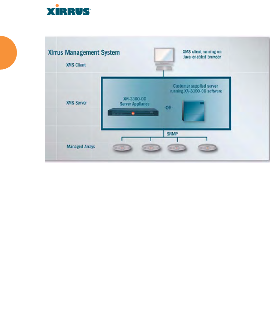
Wi-Fi Array
2 Introduction
Figure 1. The Xirrus Management System
If you need detailed information about this product, refer to the XMS
User’s Guide, part number 800-0007-001.
zXirrus Power over Gigabit Ethernet (PoGE)
The PoGE modules eliminate the need for running separate power
cabling. Additionally, an eight port module provides distributed power
to multiple Arrays, facilitating backup power when connected via a UPS.

Wi-Fi Array
Introduction 3
Nomenclature
Throughout this User’s Guide, the Xirrus Wi-Fi Array is also referred to as simply
the Array. In some instances, the terms product and unit are also used. When
discussing specific products from the Xirrus family, the product name is used (for
example, XN16, XN8, XN4). The Wi-Fi Array’s operating system is referred to as
the ArrayOS. The Web Management Interface for browser-based management of
the Array is referred to as WMI.
The Xirrus Management System is referred to as XMS. The Power over Gigabit
Ethernet system may be referred to as PoGE.
About this User’s Guide
This User’s Guide provides detailed information and procedures that will enable
wireless network administrators to install, configure and manage the Wi-Fi Array
so that end users can take full advantage of the product’s features and
functionality without technical assistance.
Organization
Topics and procedures are organized by function under the following chapter
headings:
zIntroduction
Provides a brief introduction to wireless technology, an overview of the
product, including its key features and benefits, and presents the product
specifications.
zInstalling the Wi-Fi Array
Defines the prerequisites for deploying and installing the Array and
provides instructions to help you plan and complete a successful
installation.
zThe Web Management Interface
Offers an overview of the product’s embedded Web Management
Interface, including its content and structure. It emphasizes what you
need to do to ensure that any configuration changes you make are

Wi-Fi Array
4 Introduction
applied, and provides a list of restricted characters. It also includes
instructions for logging in to the Array with your Web browser.
zViewing Status on the Wi-Fi Array
Describes the status and statistics displays available on the Array using
its embedded Web Management Interface.
zConfiguring the Wi-Fi Array
Contains procedures for configuring the Array using its embedded Web
Management Interface.
zUsing Tools on the Wi-Fi Array
Contains procedures for using utility tools provided in the Web
Management Interface. It includes procedures for upgrading the system
firmware, uploading and downloading configurations and other files,
using diagnostic tools, and resetting the Array to its factory defaults.
zThe Command Line Interface
Includes the commands and the command structure used by the Wi-Fi
Array’s Command Line Interface (CLI), and provides a procedure for
establishing a Telnet connection to the Array. This chapter also includes
some sample key configuration tasks using the CLI.
zAppendix A: Servicing the Wi-Fi Array
Contains procedures for servicing the Array, including the removal and
reinstallation of major hardware components.
zAppendix B: Quick Reference Guide
Contains the product’s factory default settings.
zAppendix C: Technical Support
Offers guidance to resolve technical issues, including general hints and
tips to enhance your product experience, and a procedure for isolating
problems within an Array-enabled wireless network. Also includes
Frequently Asked Questions (FAQs) and Xirrus contact information.
zGlossary of Terms
Provides an explanation of terms directly related to Xirrus product
technology, organized alphabetically.

Wi-Fi Array
Introduction 5
zIndex
The index is a valuable information search tool. Use the index to locate
specific topics discussed in this User’s Guide. Simply click on any page
number in the index to jump to the referenced topic.
Notes and Cautions
The following symbols are used throughout this User’s Guide:
Screen Images
Some screen images of the Web Management Interface have been modified for
clarity. For example, an image may have been cropped to highlight a specific area
of the screen, and/or sample data may be included in some fields.
Your User’s Guide as a PDF Document
This User’s Guide is also made available as a secure PDF (Portable Document
Format) file and can be viewed using the Adobe® Acrobat Reader® product. It
cannot be edited or modified. If you don’t have Acrobat Reader, you can
downloaded it free-of-charge from: http://www.adobe.com.
Hyperlinks
If you click on body text that appears in the color TEAL (with the exception of
headings or notes) the embedded hyperlink within the text will immediately take
you to the referenced destination. All internal and external cross-references,
including page numbers within the List of Figures and the Index, have associated
hyperlinks. After “jumping” to a referenced topic, if you want to return to the
previous page (reference source), simply click on Acrobat’s previous page button.
Window or Page?
Is a window a page, or is a page a window? There seems to be some dispute as to
what the correct term should be. For the sake of consistency, this document uses
#This symbol is used for general notes that provide useful supplemental
information.
!This symbol is used for cautions. Cautions provide critical information that
may adversely affect the performance of the product.

Wi-Fi Array
6 Introduction
the term Window when referring to how the Wi-Fi Array’s Web Management
Interface is displayed on your monitor.
Why Choose the Xirrus Wi-Fi Array?
The deployment of wireless LANs is becoming increasingly common as
businesses strive for greater flexibility in the workplace and the need for
employee mobility rises. The only requirements for an effective wireless
deployment are a power source, a couple of screws, and a little imagination.
Wireless LAN is also fully compatible with standard Ethernet protocols, so
connectivity with existing wired infrastructures is transparent to users—they can
still access and use the same applications and network services that they use
when plugged into the company’s wired LAN infrastructure (it’s only the plug
that no longer exists).
Wireless LAN has come a long way in the past few years and now offers the
performance, reliability and security that Enterprise customers have come to
expect from their networks. The technology is being driven by three major IEEE
standards:
z802.11a
Operates in the 5 GHz range with a maximum speed of 54 Mbps.
z802.11b
Operates in the 2.4 GHz range with a maximum speed of 11 Mbps.
z802.11g
Supports a transmission speed of 54 Mbps in the 2.4 GHz range and is
backwards compatible with 802.11b.
z802.11n
Supports a higher transmission speed of up to 300 Mbps in the 5 GHz
range and is backwards compatible with 802.11a/b/g.
Whether you’re a small company with just a handful of employees, or a large
corporation with thousands, wireless has the scalability and flexibility to serve
your needs.
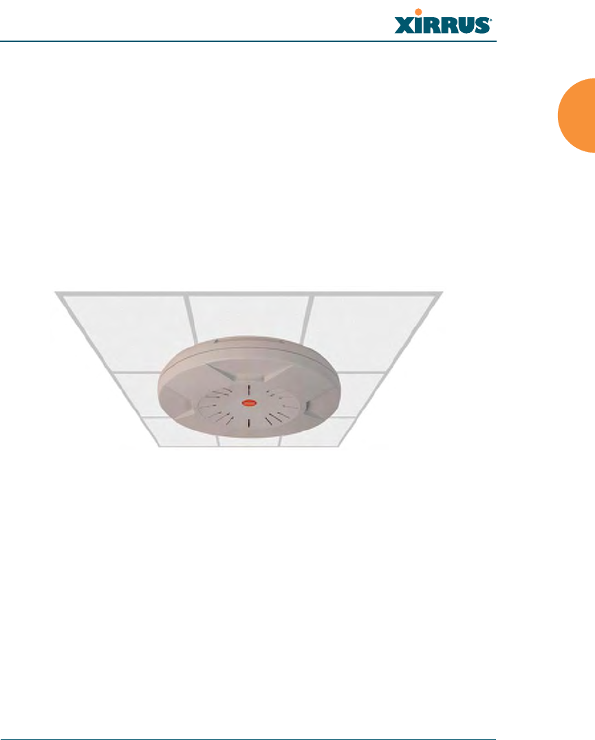
Wi-Fi Array
Introduction 7
See Also
Key Features and Benefits
Wi-Fi Array Product Overview
Product Specifications (XN4)
Product Specifications (XN16 and XN8)
The Xirrus Family of Products
Wi-Fi Array Product Overview
Part of the family of Xirrus products, the Wi-Fi Array is a high capacity, multi-
mode device designed for the Enterprise market, with twice the range and up to
sixteen times the capacity of competitive wireless products.
Figure 2. Wi-Fi Array (XN16)
The Wi-Fi Array (regardless of the product model) is Wi-Fi® compliant and
simultaneously supports 802.11a, 802.11b, 802.11g, and 802.11n clients. Enterprise
class features such as VLAN support and multiple SSID capability enable robust
network compatibility and a high level of scalability and system control.
The optional Xirrus Management System (XMS) allows global management of
hundreds of Arrays from a central location.
Multiple versions of the Array with different numbers of Integrated Access Points
(IAPs) support a variety of deployment applications: 16 IAPs (XN16), 8 IAPs
(XN8), and 4 IAPs (XN4).
Enterprise Class Security
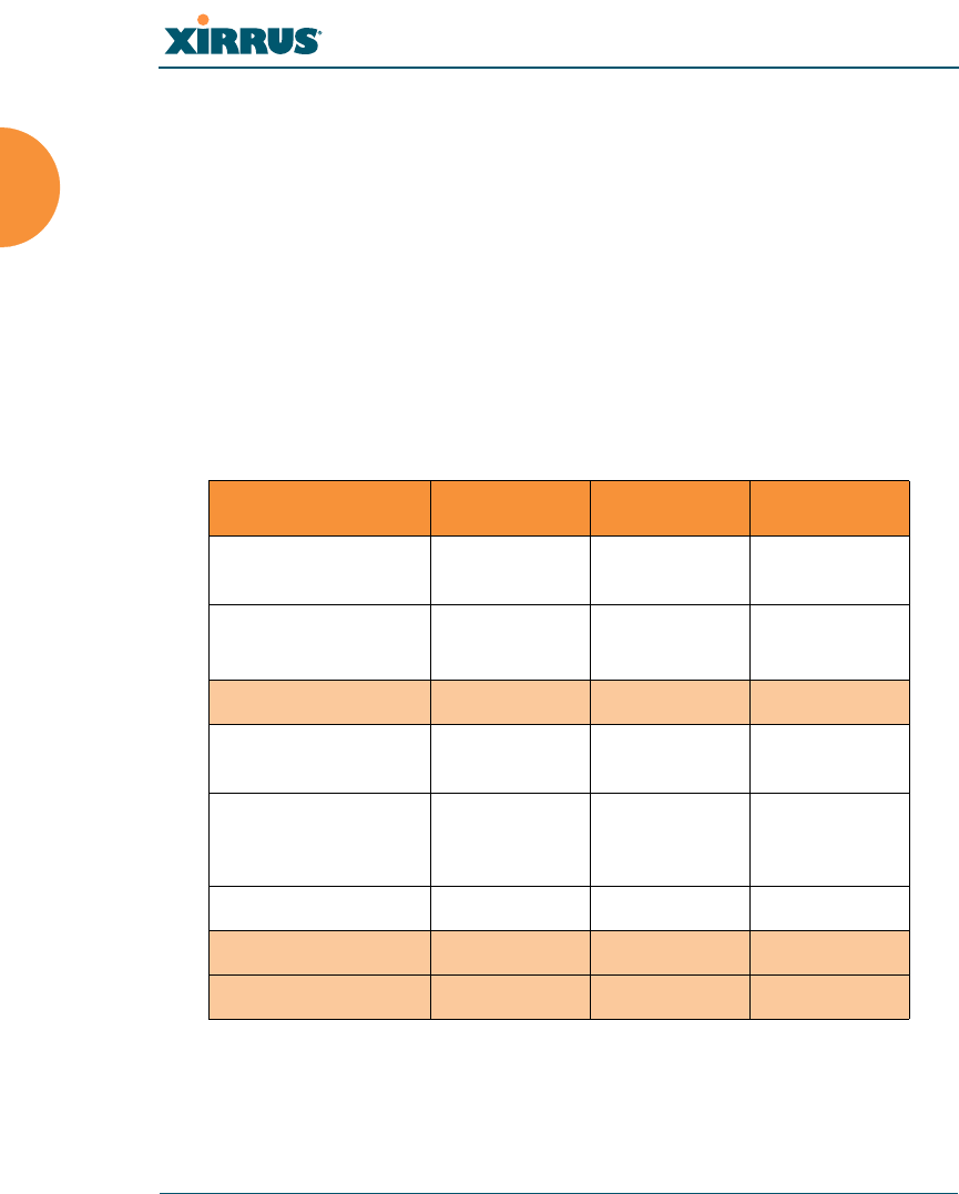
Wi-Fi Array
8 Introduction
The latest and most effective wireless encryption security standards, including
WPA (Wi-Fi Protected Access) and WPA2 with 802.11i AES (Advanced
Encryption Standard) are provided with the Wi-Fi Array. In addition, the use of
an embedded RADIUS server (or 802.1x with an external RADIUS server) ensures
user authentication—multiple Arrays can authenticate to the optional XMS,
ensuring only authorized Arrays become part of the wireless network. Rogue AP
detection, site monitoring, and RF spectrum analysis are performed in the
background by the Array automatically.
Wi-Fi Array Product Family
The following table provides an overview of the main features supported by the
Wi-Fi Array product family.
See Also
Key Features and Benefits
Wi-Fi Array Product Overview
Feature XN16 XN8, XN4
Number of 802.11
a/b/g/n radios 444
Number of
802.11a/n radios
12 4 0
Total radios 16 8 4
Integrated Wi-Fi
switch ports 16 8 4
Integrated RF
spectrum analyzer
and threat sensors
Yes Yes Yes
Uplink Ports 221
Wi-Fi bandwidth 864 432 216
Users supported 1,024 512 256
1
1
bgn using internal antennas, abg for 3 radios using external antennas
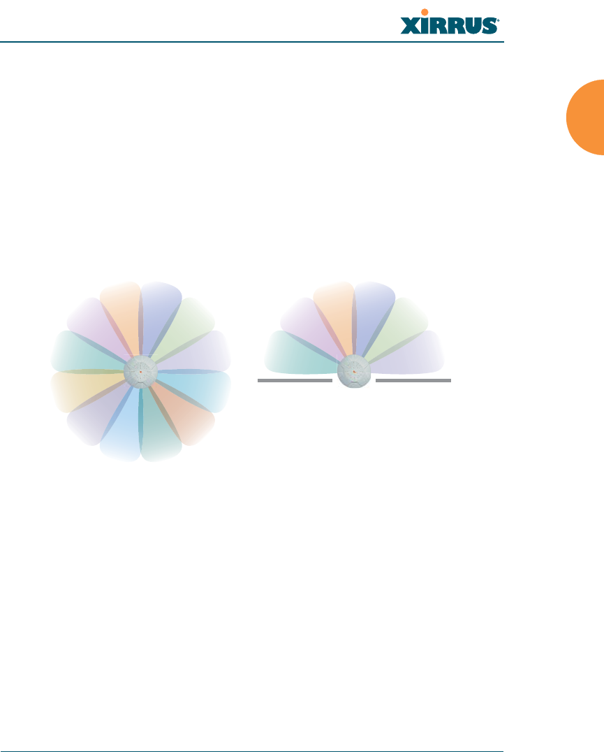
Wi-Fi Array
Introduction 9
Product Specifications (XN4)
Product Specifications (XN16 and XN8)
Power over Gigabit Ethernet (PoGE) (Optional)
Why Choose the Xirrus Wi-Fi Array?
Deployment Flexibility
Xirrus’ unique multi-radio architecture generates 360 degrees of sectored high-
gain 802.11a/b/g/n coverage that provides extended range and the highest
possible data rates for a large volume of clients. Each sector can be controlled
automatically or manually, creating a pattern of wireless coverage perfectly
tailored to individual customer needs. For example:
Figure 3. Wireless Coverage Patterns
Figure 3 depicts the following two scenarios:
zFull pattern coverage
All radios are activated with coverage spanning 360 degrees. If within
range, clients will always receive coverage regardless of their geographic
position relative to the Array.
zPartial pattern coverage
If desired, the Wi-Fi Array can be deployed close to an exterior wall. In
this case, half of all available radios have been deactivated to prevent
redundant signals from “bleeding” beyond the site’s perimeter wall. This
outside wall
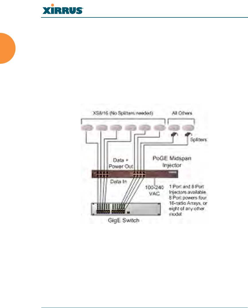
Wi-Fi Array
10 Introduction
configuration may also be used in those cases where you want to restrict
wireless coverage to selected areas of the building’s interior.
See also, “Flexible Coverage Schemes” on page 14.
Power over Gigabit Ethernet (PoGE) (Optional)
The Xirrus XP1 and XP8 Power over Gigabit Ethernet modules provide power to
your Arrays over the same Cat 5e or Cat 6 cable used for data, eliminating the
need to run power cables and provide an AC power outlet in close proximity to
each unit.
Figure 4. XP1 - Power over Ethernet Usage
Specific models of the Array are compatible with specific PoGE modules. For
details, please see “Contact Information” on page 349.
See Also
Key Features and Benefits
Wi-Fi Array Product Overview
Product Specifications (XN4)
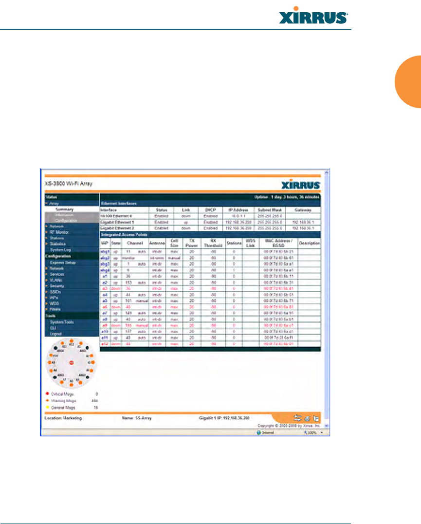
Wi-Fi Array
Introduction 11
Product Specifications (XN16 and XN8)
The Xirrus Family of Products
Why Choose the Xirrus Wi-Fi Array?
Enterprise Class Management
The Wi-Fi Array can be configured with its default RF settings, or the RF settings
can be customized using the Array’s embedded Web Management Interface
(WMI). The WMI enables easy configuration and control from a graphical
console, along with a full compliment of troubleshooting tools and statistics.
Figure 5. WMI: Array Status

Wi-Fi Array
12 Introduction
In addition, a fully featured Command Line Interface (CLI) offers IT professionals
a familiar management and control environment. SNMP (Simple Network
Management Protocol) is also supported to allow management from an SNMP
compliant management tool, such as the optional Xirrus Management System.
See Also
Key Features and Benefits
Product Specifications (XN4)
Product Specifications (XN16 and XN8)
Power over Gigabit Ethernet (PoGE) (Optional)
The Xirrus Family of Products
Why Choose the Xirrus Wi-Fi Array?
#For deployments of more than five Arrays, we recommend that you use the
Xirrus Management System (XMS). The XMS offers a rich set of features
for fine control over large deployments.
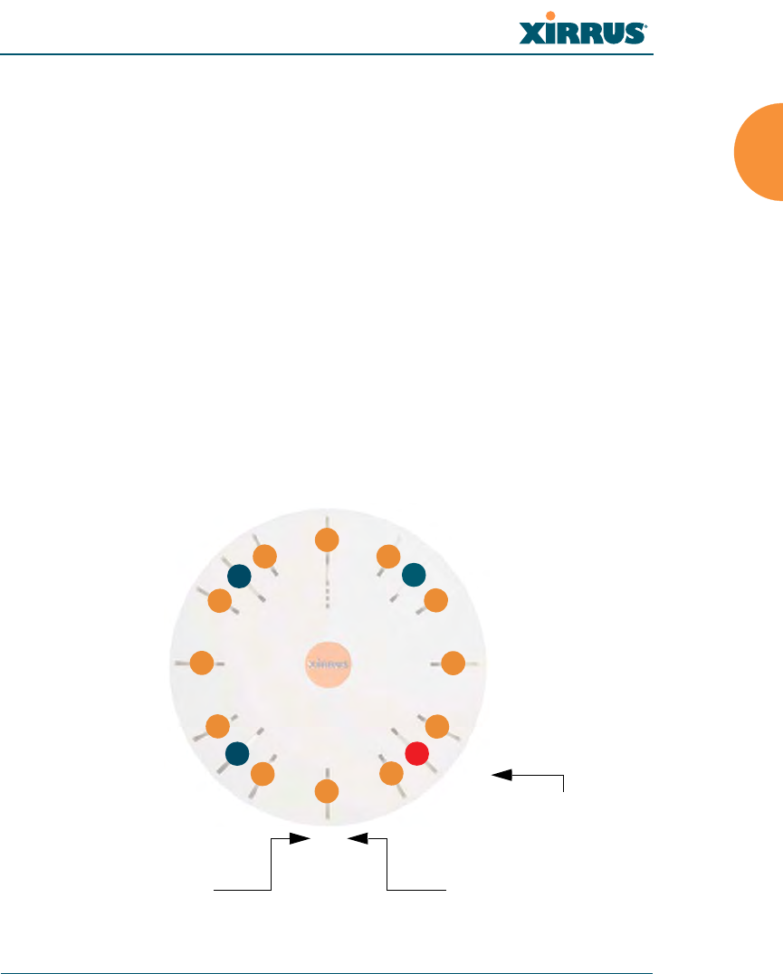
Wi-Fi Array
Introduction 13
Key Features and Benefits
This section describes some of the key product features and the benefits you can
expect when deploying the Wi-Fi Array (the XN16 product is highlighted in this
section).
High Capacity and High Performance
The XN16 version of the Wi-Fi Array easily handles time-sensitive traffic, such as
voice, and can enable wireless connectivity for 1,024 users. The unit includes two
Gigabit uplink ports for connection to the wired network. A total of sixteen IAPs
provides a maximum wireless capacity of 864 Mbps, which offers ample reserves
for the high demands of current and future applications. Of the sixteen IAPs,
twelve operate in the 802.11a/n mode and four provide backwards compatibility
with 802.11b and 802.11g.
If desired, IAP (radio) abg2 can also be configured in RF monitoring and rogue
AP detection mode.
Figure 6. Layout of IAPs (XN16)
a1
abg1
a2
a3
a4
abg2
a5
a6
a7
abg3
a8
a9
a10
abg4
a11
a12
Mode(s) IAP number
abg2 -
(RF monitoring)
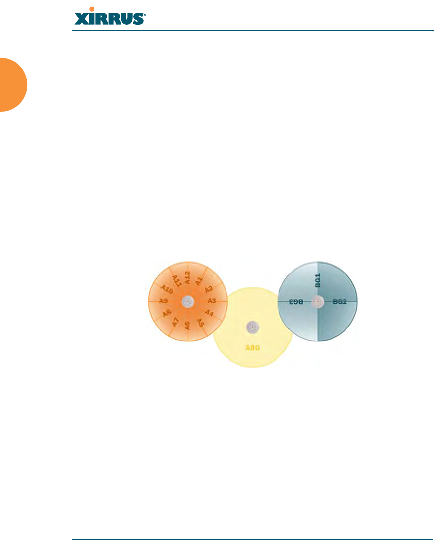
Wi-Fi Array
14 Introduction
Extended Coverage
One XN16 solution enables you to replace up to sixteen access points (includes
one omnidirectional IAP for monitoring the network). Fifteen IAP radios with
integrated directional antennas provide increased wireless range and enhanced
data rates in all directions. With a Wi-Fi Array deployed, far fewer access points
are needed and wired-like resiliency is delivered throughout your wireless
network. Your Wi-Fi Array deployment ensures:
zContinuous connectivity if an IAP (radio) fails.
zContinuous connectivity if an Array fails.
zContinuous connectivity if a WDS link or switch fails.
zContinuous connectivity if a Gigabit uplink or switch fails.
Flexible Coverage Schemes
Your Wi-Fi Array offers flexible coverage schemes for each wireless technology.
Figure 7. Coverage Schemes
z802.11a/n
Delivers 60° wireless coverage per IAP, with 6 dBi of gain.
z802.11a/b/g/n
Delivers 180° wireless coverage, with 4 dBi of gain.
z802.11a/b/g/n (monitor only)
Delivers 360° wireless coverage, with 2 dBi of gain.
802.11a/n
Monitor only
802.11a/b/g/n

Wi-Fi Array
Introduction 15
Non-Overlapping Channels
Complete use of non-overlapping channels limits interference and delivers
maximum capacity. On the XN16, up to 16 non-overlapping channels are fully
utilized across the 5GHz and 2.4GHz spectrums (up to 12 across the 5GHz
spectrum plus up to 3 across the 2.4 GHz spectrum—typically, one additional
radio is used as a dedicated RF monitor).
Secure Wireless Access
Multiple layers of authentication and encryption ensure secure data
transmissions. The Wi-Fi Array is 802.11i compliant with encryption support for
40 bit and 128 bit WEP, WPA and WPA2 with TKIP and AES encryption.
Authentication support is provided via 802.1x, including PEAP, EAP-TLS, EAP-
TTLS, and LEAP (Lightweight Extensible Authentication Protocol) passthrough.
Applications Enablement
QoS (Quality of Service) functionality combined with true switch capabilities
enable high density video and Voice over Wireless LAN deployments. Compliant
with 802.1p and 802.1Q standards.
SDMA Optimization
SDMA (Spatial Division Multiple Access) technology provides full 360° coverage
while allowing independent channel and power output customization. Also
supports fast inter-zone handoffs for time-sensitive applications and roaming
support.
Fast Roaming
Utilizes the Xirrus Roaming Protocol (XRP) ensuring fast and seamless roaming
capabilities between IAPs or Arrays at both Layer 2 and Layer 3.
Easy Deployment
The Xirrus Management System (XMS) offers real time monitoring and
management capabilities of the wireless network—ideal for the Enterprise
market. It also allows you to import floor plans to help you plan your
deployment. The Xirrus Wi-Fi Array chassis has a plenum rated, lockable and
tamper resistant case.

Wi-Fi Array
16 Introduction
See Also
Wi-Fi Array Product Overview
Product Specifications (XN4))
Product Specifications (XN16 and XN8)
Power over Gigabit Ethernet (PoGE) (Optional)
The Xirrus Family of Products
Why Choose the Xirrus Wi-Fi Array?
Product Specifications (XN16 and XN8)
Element Specifications
Number of Users Maximum of 64 associated users per radio
1024 users per Array (XN16)
512 users per Array (XN8)
Physical Diameter: 18.65 inches (47.37 cm)
Height: 3.87 inches (9.83 cm)
Weight: 8lbs (3.63 kg)
Environmental Operating Temperature:
-10°C to 50°C
0% to 90% relative humidity (non-condensing)
Storage Temperature:
-20°C to 60°C
5% to 95% relative humidity (non-condensing)
System 1 GHz CPU (XN16/XN8)
1 GB RAM (XN16/XN8)
512 MB system flash
Expansion slot for future options

Wi-Fi Array
Introduction 17
Electrical XN16/XN8:
Each Array supports both AC and PoGE
AC Input Power: 90-265VAC at 47-63Hz
PoGE Input Power: Power over Gigabit
Ethernet—no splitter required, 48VDC
Interfaces Serial:
1 x RS232 – RJ45 connector
Ethernet Interfaces:
2 x Gigabit 100/1000 Mbps w/failover
1 x Fast Ethernet 10/100 Mbps
Status LEDs:
System status, Ethernet, Radio
Management Web-based HTTPS
SNMP v2
CLI via SSHv2 or Telnet
FTP
TFTP
Serial
Xirrus Management System (XMS)
Syslog reporting for alerts/alarms
Networking DHCP client, DHCP server, NTP client, NAT
VLAN Support 802.1Q, 802.1p VLAN
Supports up to 16 VLANs
Multiple SSID
Support
Allows up to 16 separate SSIDs to be defined
with map security, VLAN and QoS settings for
each SSID
Element Specifications

Wi-Fi Array
18 Introduction
Performance Client Load Balancing
Automatic load balancing between system
radios
Quality of Service:
802.1p wired traffic prioritization
Wireless packet prioritization
MAP CoS to TCID
Fair queuing of downstream traffic
Security Wireless Security:
WEP 40bit/128bit encryption
WPA and WPA2 with TKIP and AES encryption
Rogue AP detection, with alerts and
classification
User and System Authentication:
WPA and WPA2 Pre-Shared Key authentication
Internal RADIUS Server, supports EAP-PEAP
only
802.1x EAP-TLS
802.1x EAP-TTLS/MSCHAPv2
802.1x PEAPv0/EAP-MSCHAPv2
802.1x PEAPv1/EAP-GTC
802.1x EAP-SIM
802.1x EAP-LEAP Passthrough
External RADIUS servers
Authentication of Wi-Fi Arrays to the Xirrus
Management System (XMS)
Element Specifications

Wi-Fi Array
Introduction 19
Wireless Number of Radios:
XN16: 12 x 802.11a/n radios
4 x 802.11a/b/g/n radios
Only 12 radios should be used as 802.11a/n
radios concurrently.
XN8: 4 x 802.11a/n radios
4 x 802.11a/b/g/n radios
Wireless Standards:
802.11a/b/g /n and g-only mode
802.11e, 802.11i
Channel Selection:
Manual and Automatic
Frequency Bands:
11a: 4.945 – 4.985 (restricted Public Safety band)
11a: 5.15-5.25 GHz (UNII 1)
11a: 5.725-5825 GHz (UNII 3)
11b/g: 2.412-2.462 GHz (FCC)
Antennas (XN16):
36 x internal 6 dBi 60° 802.11a/n sectorized
12 x internal 3 dBi 180° 802.11b/g/n sectorized
1 x internal 2 dBi 360° omni-directional (for RF
monitoring)
3 x external RP-TNC connectors for three
802.11a/b/g/n radios
Element Specifications

Wi-Fi Array
20 Introduction
See Also
Key Features and Benefits
Wi-Fi Array Product Overview
Product Specifications (XN4)
Power over Gigabit Ethernet (PoGE) (Optional)
The Xirrus Family of Products
Why Choose the Xirrus Wi-Fi Array?
Antennas (XN8):
24 x internal 6 dBi 60° 802.11a sectorized
12 x internal 3 dBi 180° 802.11b/g sectorized
1 x internal 2 dBi 360° omni-directional (for RF
monitoring)
3 x external RP-TNC connectors for three
802.11a/b/g/n radios
Radio Approvals:
FCC (United States)
Compliance FCC Part 15.107 and 15109, Class B
Warranty One year (hardware and software)
Element Specifications

Wi-Fi Array
Introduction 21
Product Specifications (XN4)
Element Specifications
Number of Users Maximum of 64 associated users per radio (256
users per Array)
Physical Diameter: 12.58 inches (31.95 cm)
Height: 2.58 inches (6.55 cm)
Weight: 4lbs (1.81 kg)
Environmental Operating Temperature:
-10°C to 50°C
0% to 90% relative humidity (non-condensing)
Storage Temperature:
-20°C to 60°C
5% to 95% relative humidity (non-condensing)
System 825 MHz CPU (XN4)
512 MB RAM, expandable (XN4)
512 MB system flash, expandable
Expansion slot for future options
Electrical XN4:
Each Array supports both AC and PoGE
AC Input Power: 90-265VAC at 47-63Hz
Power over Gigabit Ethernet (PoGE): all 4-port
models work with all Xirrus PoGE modules,
splitter required, 48VDC
Interfaces Serial:
1 x RS232 – RJ45 connector
Ethernet Interfaces:
1 x Gigabit 100/1000 Mbps
Status LEDs:
System status, Ethernet, Radio

Wi-Fi Array
22 Introduction
Management Web-based HTTPS
SNMP v2
CLI via SSHv2 or Telnet
FTP
TFTP
Serial
Xirrus Management System (XMS)
Syslog reporting for alerts/alarms
Networking DHCP client, DHCP server, NTP client, NAT
VLAN Support 802.1Q, 802.1p VLAN
Supports up to 16 VLANs
Multiple SSID
Support
Allows up to 16 separate SSIDs to be defined
with map security, VLAN and QoS settings for
each SSID
Performance Client Load Balancing
Automatic load balancing between system
radios
Quality of Service:
802.1p wired traffic prioritization
Wireless packet prioritization
MAP CoS to TCID
Fair queuing of downstream traffic
Element Specifications

Wi-Fi Array
Introduction 23
Security Wireless Security:
WEP 40bit/128bit encryption
WPA and WPA2 with TKIP and AES encryption
Rogue AP detection, with alerts and
classification
User and System Authentication:
WPA Pre-Shared Key authentication
Internal RADIUS Server, supports EAP-PEAP
only
802.1x EAP-TLS
802.1x EAP-TTLS/MSCHAPv2
802.1x PEAPv0/EAP-MSCHAPv2
802.1x PEAPv1/EAP-GTC
802.1x EAP-SIM
802.1x EAP-LEAP Passthrough
External RADIUS servers
Authentication of Wi-Fi Arrays to the Xirrus
Management System (XMS)
Element Specifications

Wi-Fi Array
24 Introduction
See Also
Key Features and Benefits
Wi-Fi Array Product Overview
Product Specifications (XN16 and XN8)
Power over Gigabit Ethernet (PoGE) (Optional)
The Xirrus Family of Products
Why Choose the Xirrus Wi-Fi Array?
Wireless Number of Radios:
4 x 802.11a/b/g/n radios
Wireless Standards:
802.11a/b/g/n and g-only mode
802.11e, 802.11i
Channel Selection:
Manual and Automatic
Frequency Bands:
11a: 4.945 – 4.985 (restricted Public Safety band)
11a: 5.15-5.25 GHz (UNII 1)
11a: 5.725-5825 GHz (UNII 3)
11b/g: 2.412-2.462 GHz (FCC)
Antennas:
12 x internal 6 dBi 60° 802.11a sectorized
12 x internal 3 dBi 180° 802.11b/g sectorized
1 x internal 2 dBi 360° omni-directional (for RF
monitoring)
3 x external RP-TNC connectors for three
802.11a/b/g/n radios
Radio Approvals:
FCC (United States)
Compliance FCC Part 15.107 and 15109, Class B
Warranty One year (hardware and software)
Element Specifications

Wi-Fi Array
Introduction 25

Wi-Fi Array
26 Introduction

Wi-Fi Array
Installing the Wi-Fi Array 27
Installing the Wi-Fi Array
The instructions for completing a successful installation include the following
topics:
z“Installation Prerequisites” on page 27.
z“Planning Your Installation” on page 30.
z“Installation Workflow” on page 49.
z“Unpacking the Wi-Fi Array” on page 50.
z“Installing Your Wi-Fi Array” on page 52.
z“Powering Up the Wi-Fi Array” on page 73.
z“Establishing Communication with the Array” on page 76.
z“Performing the Express Setup Procedure” on page 77.
Installation Prerequisites
Your Wi-Fi Array deployment requires the presence of hardware and services in
the host wired/wireless network, including:
zDedicated AC power outlet
Unless you are using Xirrus PoGE, you need a dedicated power outlet to
supply AC power to each unit deployed at the site. If you are using the
optional PoGE, then power is supplied over the same Cat 5e or Cat 6
cable used for data. PoGE power injector modules are available in 1 port
and 8 port configurations and are typically placed near your Gigabit
Ethernet switch. An AC outlet is required for each injector module.
zEthernet port
You need at least one 100/1000 BaseT port to establish wired Gigabit
Ethernet connectivity (via the product’s Gigabit 1 or Gigabit 2 port) and
one 10/100 BaseT port (if desired) for product management.
!The Array’s Ethernet ports should be connected to an Ethernet switch, not
an Ethernet hub—if a hub is used, we recommend that you connect only
one Ethernet port.
Wi-Fi Array
28 Installing the Wi-Fi Array
zSecure Shell (SSH) utility
To establish secure remote command line access to the Array, you need a
Secure Shell (SSH) utility, such as PuTTY.
zSecure Web browser
Either Internet Explorer (version 6.0 or higher), Netscape Navigator
(version 7.0 or higher), or Mozilla Firefox (version 1.01 or higher).
A secure Web browser is required for Web-based management of the
Array. The browser must be on the same subnet as the Array, or you must
set a static route for management as described in the warning above.
zSerial connection capability
To connect directly to the console port on the Array, your computer must
be equipped with a male 9-pin serial port and terminal emulation
software (for example, HyperTerminal). The Xirrus Array only supports
serial cable lengths up to 25’ per the RS-232 specification.
Use the following settings when establishing a serial connection:
!The Gigabit1 Ethernet interface is the primary port for both data and
management traffic. If a single Ethernet connection is used, it must be
connected to the Gigabit1 Ethernet interface. See also, “Port Failover
Protection” on page 40.
The 10/100 Ethernet Port may be used for managing the Array out of
band from the Gigabit Ethernet ports. The 10/100 port will route only
management traffic, using a static route that may be configured for this
interface. See “interface” on page 273.
Bits per second 115,200
Data bits 8
Parity None
Stop bits 1
Flow control None

Wi-Fi Array
Installing the Wi-Fi Array 29
Optional Network Components
The following network components are optional.
zXirrus Management System (XMS)
The optional XMS offers powerful management features for small or large
Wi-Fi Array deployments.
zXirrus Power over Gigabit Ethernet (PoGE)
The optional Power over Gigabit Ethernet (PoGE) modules allow you to
provide power the Array without running power cables. The 8 Port
Injector provides distributed power to multiple Arrays, eliminating the
need to run dedicated AC power to each unit and facilitating backup
power when connected via a UPS.
Specific models of the Array are compatible with specific PoGE modules.
For details, please see “Contact Information” on page 349.
zExternal RADIUS server
Although your Array comes with an embedded RADIUS server, for
802.1x authentication in large deployments you may want to add an
external RADIUS server.
Client Requirements
The Wi-Fi Array should only be used with Wi-Fi certified client devices.
See Also
Coverage and Capacity Planning
Deployment Examples
Failover Planning
Planning Your Installation
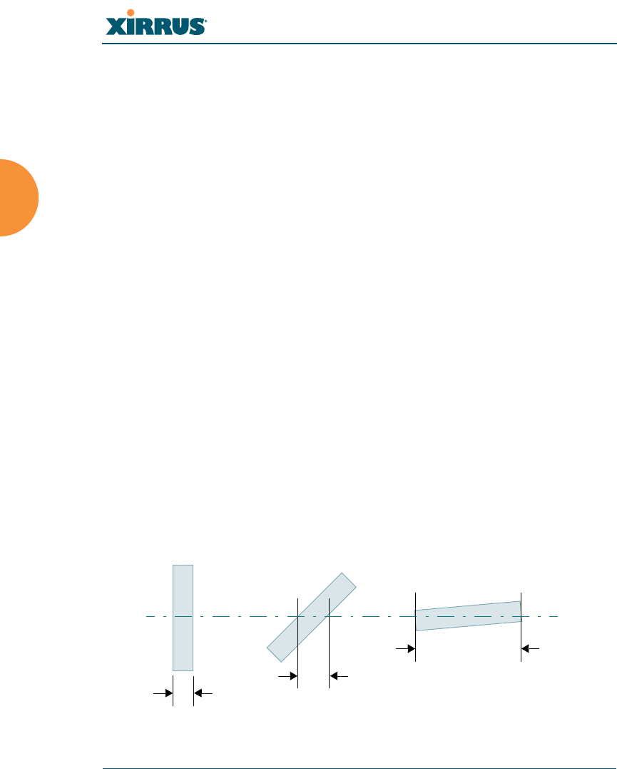
Wi-Fi Array
30 Installing the Wi-Fi Array
Planning Your Installation
This section provides guidelines and examples to help you plan your Xirrus Wi-Fi
Array deployment to achieve the best overall coverage and performance. We
recommend you conduct a site survey to determine the best location and settings
for each Array you install.
General Deployment Considerations
The Wi-Fi Array’s unique multi-radio architecture generates 360 degrees of
sectored high-gain 802.11a/b/g/n coverage that provides extended range.
However, the number, thickness and location of walls, ceilings or other objects
that the wireless signals must pass through may affect the range. Typical ranges
vary depending on the types of materials and background RF (radio frequency)
noise at your location. To maximize wireless range, follow these basic guidelines:
1. Keep the number of walls and ceilings between the Array and your
receiving devices to a minimum—each wall or ceiling can reduce the
wireless range from between 3 and 90 feet (1 to 30 meters). Position your
devices so that the number of walls or ceilings is minimized.
2. Be aware of the direct line between each device. For example, a wall that
is 1.5 feet thick (half a meter) at 90° is actually almost 3 feet thick (or 1
meter) when viewed at a 45° angle. At an acute 2° degree angle the same
wall is over 42 feet (or 14 meters) thick! For best reception, try to ensure
that your wireless devices are positioned so that signals will travel
straight through a wall or ceiling.
Figure 8. Wall Thickness Considerations
90° 45°
1.5 feet/
.5 m ~ 3 feet/
1 m
> 42 feet\
14 m
2°

Wi-Fi Array
Installing the Wi-Fi Array 31
3. Try to position wireless client devices so that the signal passes through
drywall (between studs) or open doorways and not other materials that
can adversely affect the wireless signal.
See Also
Coverage and Capacity Planning
Deployment Examples
Deployment Summary
Installation Prerequisites
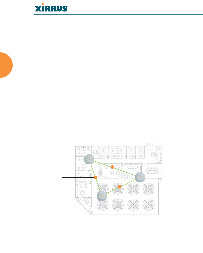
Wi-Fi Array
32 Installing the Wi-Fi Array
Coverage and Capacity Planning
This section considers coverage and capacity for your deployment(s), including
placement options, RF patterns and cell sizes, area calculations, roaming
considerations, and channel allocations.
Placement
Use the following guidelines when considering placement options:
1. The best placement option for the Array is ceiling-mounted within an
open plan environment (cubicles rather than fixed walls).
2. Keep the Array away from electrical devices or appliances that generate
RF noise. Because the Array is generally mounted on ceilings, be aware of
its position relative to lighting (especially fluorescent lighting)—we
recommend maintaining a distance of at least 3 to 6 feet (1 to 2 meters).
3. If using multiple Arrays in the same area, maintain a distance of at least
100 ft/30m between Arrays if there is direct line-of-sight between the
units, or at least 50 ft/15m if a wall or other barrier exists between the
units.
Figure 9. Unit Placement
100 ft/ 30m
100 ft/ 30 m
100 ft/
30 m

Wi-Fi Array
Installing the Wi-Fi Array 33
RF Patterns
The Wi-Fi Array allows you to control—automatically or manually—the pattern
of wireless coverage that best suits your deployment needs. You can choose to
operate with full coverage, half coverage, or custom coverage (by enabling or
disabling individual sectors).
Full (Normal) Coverage
In normal operation, the Array provides a full 360 degrees of coverage.
Figure 10. Full (Normal) Coverage
Half Coverage
If installing a unit close to an exterior wall, you can deactivate half of the radios to
prevent redundant signals from “bleeding” beyond the wall and extending
service into public areas. The same principle applies if you want to restrict service
to an adjacent room within the site.
Figure 11. Adjusting RF Patterns
outside wall
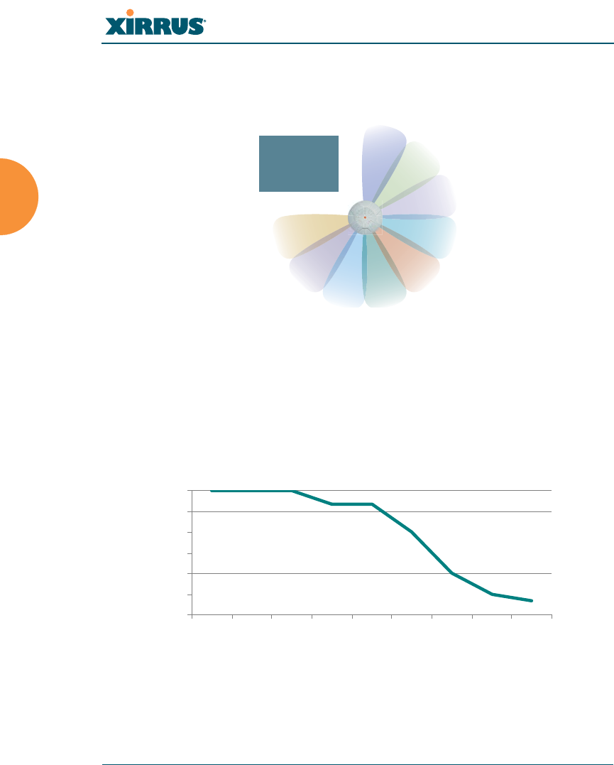
Wi-Fi Array
34 Installing the Wi-Fi Array
Custom Coverage
Where there are highly reflective objects in close proximity to the Array, you can
turn off specific radios to avoid interference and feedback.
Figure 12. Custom Coverage
Capacity and Cell Sizes
Cell sizes should be estimated based on the number of users, the applications
being used (for example, data/video/voice), and the number of Arrays available
at the location. The capacity of a cell is defined as the minimum data rate desired
for each sector multiplied by the total number of sectors being used.
Figure 13. Connection Rate vs. Distance (relatively unobstructed area)
object
reflective
0
9
18
27
36
45
54
10
(3m)
50 100
(30m)
150 200
(60m)
250 300
(90m)
350
Distance (feet)
Connection Rate (Mbps)

Wi-Fi Array
Installing the Wi-Fi Array 35
Figure 13 shows some sample maximum connection rates for the XN8 and XN16
at different distances in an unobstructed area. Wireless environments can vary
greatly so the actual rates may be different depending on the specific network
deployment.
Fine Tuning Cell Sizes
Adjusting the transmit power allows you to fine tune cell sizes. There are four
standard sizes—Small, Medium, Large, or Max (the default is Max). There is also
an Auto setting that automatically determines the best cell size, and a Manual
setting that allows you to choose your power settings directly. If you are installing
many units in close proximity to each other, reduce the transmit power to avoid
excessive interference with other Arrays or installed APs. See also, “Coverage and
Capacity Planning” on page 32.
Figure 14. Transmit Power
Sharp Cell
This feature available from the Web Management Interface reduces interference
between neighboring Wi-Fi Arrays or other Access Points by limiting to a defined
#The XN4 has a smaller range than the larger Arrays. The distance is about
80% of the values shown in Figure 13 above. Thus the maximum cell size is
about 64% of the coverage area in the chart.
Large
Medium
Small
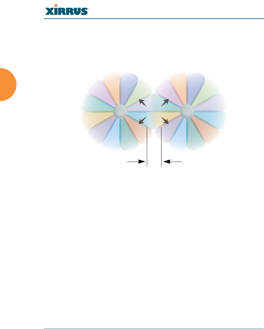
Wi-Fi Array
36 Installing the Wi-Fi Array
boundary (cell size) the trailing edge bleed of RF energy. To enable the Sharp Cell
feature, go to “Global Settings (IAP)” on page 209.
Roaming Considerations
Cells should overlap approximately 10 - 15% to accommodate client roaming.
Figure 15. Overlapping Cells
Allocating Channels
Because the Wi-Fi Array is a multi-channel device, allocating the best channels to
radios is important if peak performance is to be maintained.
Automatic Channel Selection
We recommend that you allow the Array to make intelligent channel allocation
decisions automatically. In the automatic mode, channels are allocated
dynamically, driven by changes in the environment.
ROAMING
10 - 15% overlap

Wi-Fi Array
Installing the Wi-Fi Array 37
Manual Channel Selection
You can manually assign channels on a per radio basis, though manual selection
is not recommended (and not necessary).
Figure 16. Allocating Channels Manually
See Also
Deployment Examples
Failover Planning
Installation Prerequisites
#To avoid co-channel interference, do not select adjacent channels for radios
that are physically next to each other.
Maintain channel separation
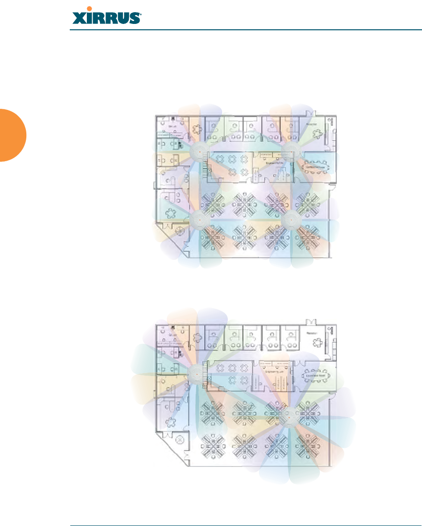
Wi-Fi Array
38 Installing the Wi-Fi Array
Deployment Examples
The following examples employ 802.11a cells, each offering minimum
throughputs of 54 Mbps, 36 Mbps, and 18 Mbps per sector respectively, and
assume a floor plan covering a total area of about 60,000 square feet (5574 sq m).
Figure 17. Deployment Scenario (54 Mbps)—Per Sector
Figure 18. Deployment Scenario (36 Mbps)—Per Sector
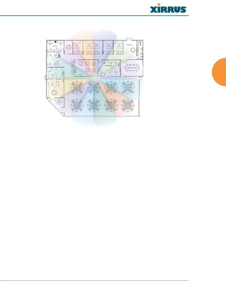
Wi-Fi Array
Installing the Wi-Fi Array 39
Figure 19. Deployment Scenario (18 Mbps)—Per Sector
See Also
Coverage and Capacity Planning
Failover Planning
Planning Your Installation
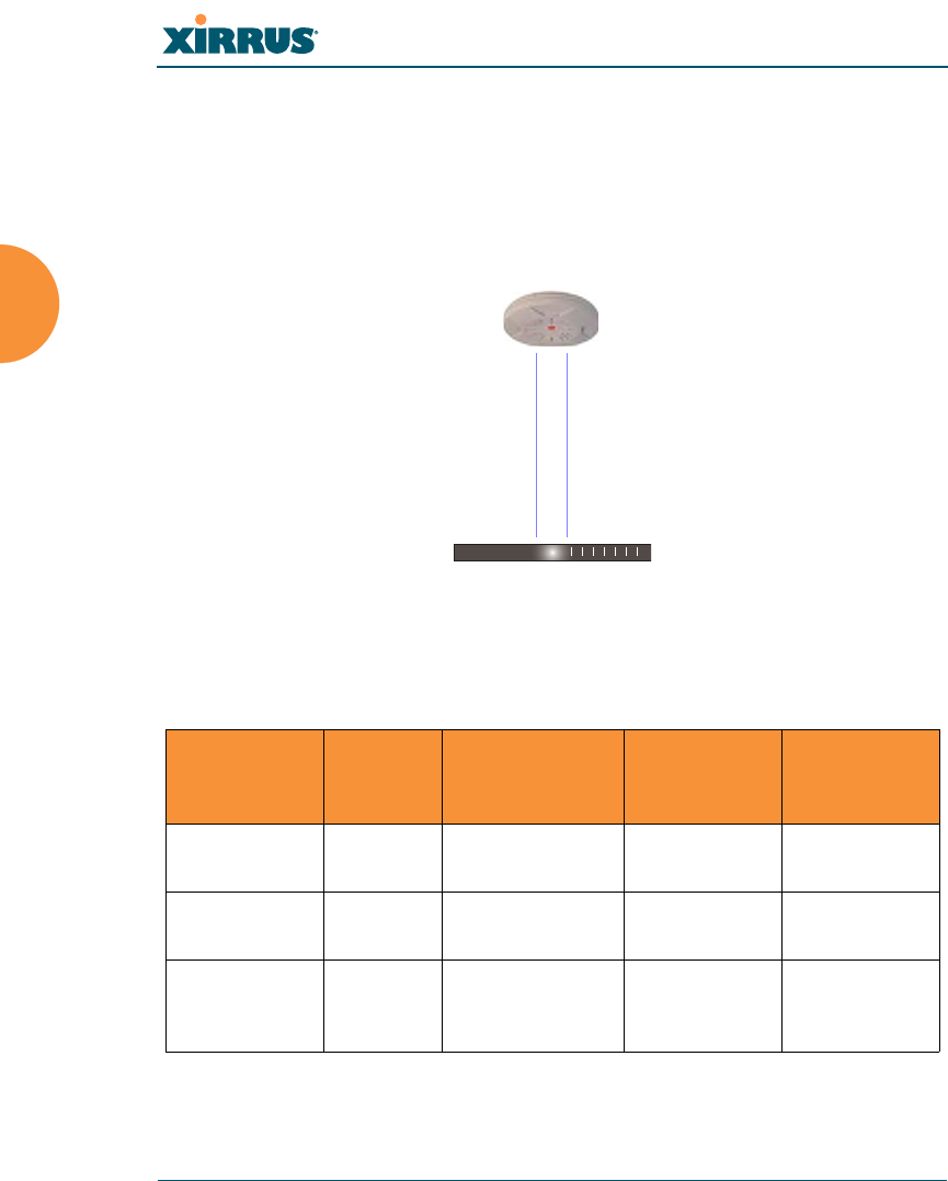
Wi-Fi Array
40 Installing the Wi-Fi Array
Failover Planning
This section discusses failover protection at the unit and port levels.
Port Failover Protection
To ensure that service is continued in the event of a port failure, you can utilize
the Gigabit 1 and Gigabit 2 ports simultaneously.
Figure 20. Port Failover Protection
In addition, the Array has full failover protection between the Gigabit 1 and
Gigabit 2 Ethernet ports (see following table).
Interface Bridges
Data?
Bridges
Management
Traffic?
Fails Over To: IP address
Fast Ethernet No Yes None DHCP or
static
Gigabit 1 Yes Yes Gigabit 2 DHCP or
static
Gigabit 2 Yes Yes Gigabit 1 Assumes the
IP address of
Gigabit 1
Ethernet switch
Multiple port connections
Wi-Fi Array
Installing the Wi-Fi Array 41
Switch Failover Protection
To ensure that service is continued in the event of a switch failure, you can
connect Arrays to more than one Ethernet switch (not a hub).
Figure 21. Switch Failover Protection
See Also
Coverage and Capacity Planning
Deployment Examples
Installation Prerequisites
Network Management Planning
Planning Your Installation
Power Planning
Security Planning
#Gigabit Ethernet connections must be on the same subnet.
Ethernet switch Backup switch
Ethernet connections

Wi-Fi Array
42 Installing the Wi-Fi Array
Power Planning
The XN8 and XN16 Array models and all four-port Arrays support both AC
power and Power over Gigabit Ethernet (PoGE). This section discusses the AC
and PoGE power options.
AC Power
The AC power option requires a direct connection between the Array and a
dedicated AC power outlet. The power cord is provided with the unit.
Power over Gigabit Ethernet
To deliver power to the Array, you may use the optional XP1 or XP8 Power over
Gigabit Ethernet (PoGE) modules. They provide power over Cat 5e or Cat 6 cables
to the Array without running power cables—see Figure 4 on page 10.
Specific models of the Array are compatible with specific PoGE modules. For
details, please see “Contact Information” on page 349.
See Also
Coverage and Capacity Planning
Deployment Examples
Failover Planning
Network Management Planning
Security Planning
Security Planning
This section offers some useful guidelines for defining your preferred encryption
and authentication method. For additional information, see “Understanding
Security” on page 165 and the Security section of “Frequently Asked Questions”
on page 334.
Wireless Encryption
Encryption ensures that no user can decipher another user’s data transmitted
over the airwaves. There are three encryption options available to you, including:
#When using Cat 5e or Cat 6 cable, power can be provided up to a distance of
100m.

Wi-Fi Array
Installing the Wi-Fi Array 43
zWEP-40bit or WEP-128bit
Because WEP is vulnerable to cracks, we recommend that you only use
this for legacy devices that cannot support a stronger encryption type.
zWi-Fi Protected Access (WPA)
This is much more secure than WEP and uses TKIP for encryption.
zWi-Fi Protected Access (WPA2) with AES
This is government-grade encryption—available on most new client
adapters—and uses the AES–CCM encryption mode (Advanced
Encryption Standard–Counter Mode).
Authentication
Authentication ensures users are who they say they are, and occurs when users
attempt to join the wireless network and periodically thereafter. The following
authentication methods are available with the Wi-Fi Array:
zRADIUS 802.1x
802.1x uses a remote RADIUS server to authenticate large numbers of
clients, and can handle different authentication methods (EAP-TLS, EAP-
TTLS, EAP-PEAP, and EAP-LEAP Passthrough).
zXirrus Internal RADIUS server
Recommended for smaller numbers of users (about 100 or less). Supports
EAP-PEAP only
zPre-Shared Key
Uses a pass-phrase or key that is manually distributed to all authorized
users. The same passphrase is given to client devices and entered into
each Array.
zMAC Access Control Lists (ACLs)
MAC access control lists provide a list of client adapter MAC addresses
that are allowed or denied access to the wireless network, and can be
used in addition to any of the above authentication methods. ACLs are
good for embedded devices, like printers and bar-code scanners (though
MAC addresses can be spoofed). The Wi-Fi Array supports 1,000 ACL
entries.

Wi-Fi Array
44 Installing the Wi-Fi Array
See Also
Failover Planning
Network Management Planning
Power Planning

Wi-Fi Array
Installing the Wi-Fi Array 45
Network Management Planning
Network management can be performed using any of the following methods:
zCommand Line Interface, using an SSH (Secure Shell) utility, like PuTTY.
zWeb-based management, using the Array’s embedded Web Management
Interface (WMI). This method provides configuration and basic
monitoring tools, and is good for small deployments (one or two units).
zCentralized Web-based management, using the optional Xirrus
Management System (XMS), which can be run on a dedicated Xirrus
appliance (XM-3300) or your own server. The XMS is used for managing
large Wi-Fi Array deployments from a centralized Web-based interface
and offers the following features:
Globally manage large numbers of Arrays (up to 500)
Seamless view of the entire wireless network
Easily configure large numbers of Arrays
Rogue AP monitoring
Easily manage system-wide firmware updates
Monitor performance and trends
Aggregation of alerts and alarms
See Also
Failover Planning
Power Planning
Security Planning
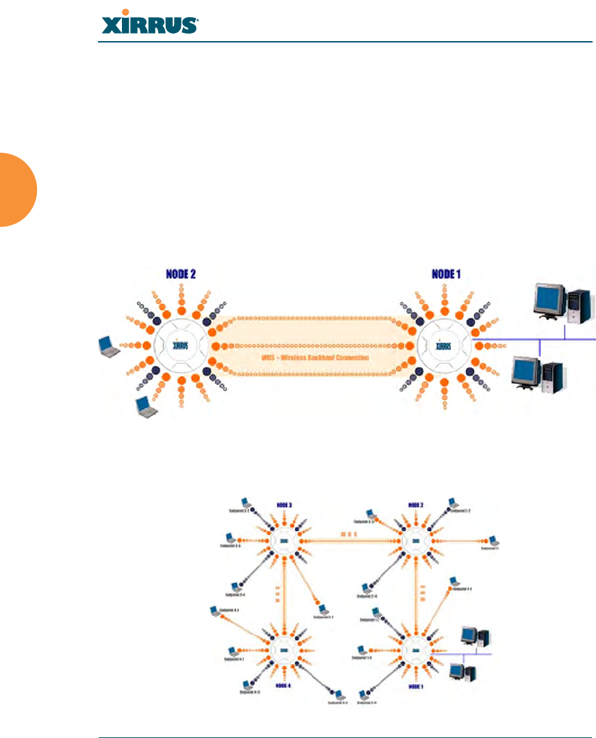
Wi-Fi Array
46 Installing the Wi-Fi Array
WDS Planning
WDS (Wireless Distribution System) creates wireless backhauls between arrays,
allowing your wireless network to be expanded using multiple Arrays without
the need for a wired backbone to link them (see Figure 22). WDS features include:
zOne to three IAPs may be used to form a WDS link, yielding up to 162
Mbps bandwidth per link. Up to 4 WDS links may be defined per Array.
zAutomatic IAP Load Balancing
zClients can still associate to a BSS on the same radio interface used for a
WDS Host Link. This will take bandwidth from the WDS link.
Figure 22. WDS Link
zMultiple links per Array allow you to configure multi-hop connections.
Figure 23. A Multiple Hop WDS Connection
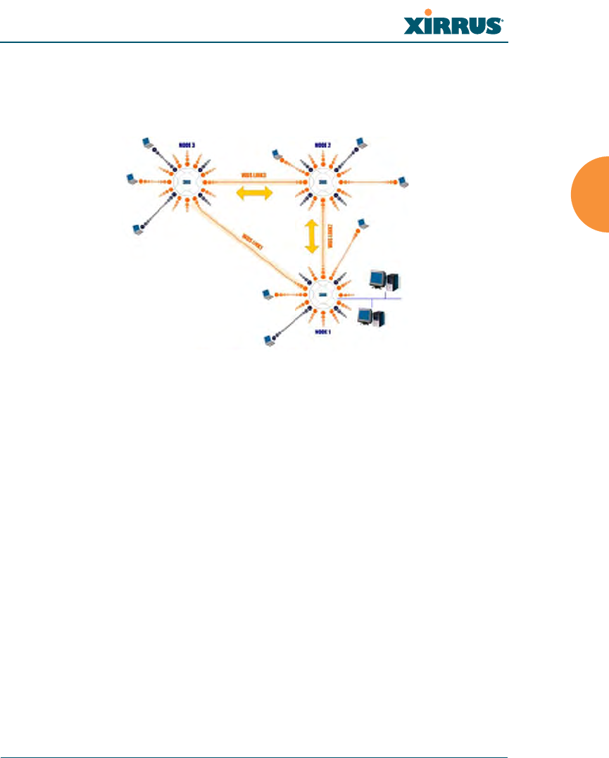
Wi-Fi Array
Installing the Wi-Fi Array 47
zMultiple WDS links can provide link redundancy (failover capability - see
Figure 24). A network protocol (Spanning Tree Protocol—STP) prevents
Arrays from forming network loops.
Figure 24. WDS Failover Protection
WDS links have a Host/Client relationship similar to the usual IAP/station
pattern for Arrays:
zA WDS Client Link associates/authenticates to a host (target) Array in the
same way that a station associates to an IAP. The client side of the link
must be configured with the root MAC address of the target (host) Array.
zA WDS Host Link acts like an IAP by allowing one WDS Client Link to
associate to it. An Array may have both client and host links.
WDS configuration is performed only on the client-side Array. See “WDS” on
page 229. Note that both Arrays must be configured with the same SSID name.
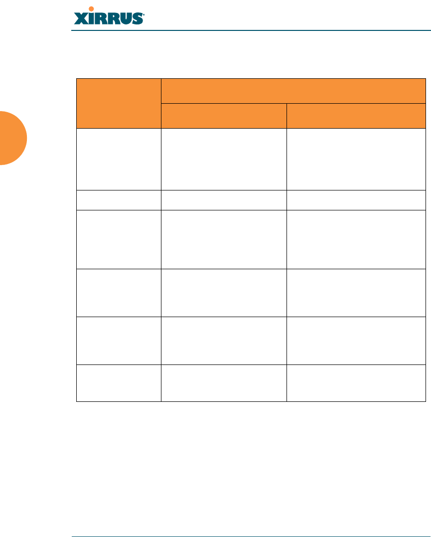
Wi-Fi Array
48 Installing the Wi-Fi Array
Deployment Summary
The following table summarizes your deployment options.
See Also
Coverage and Capacity Planning
Deployment Examples
Network Management Planning
Planning Your Installation
Power Planning
Security Planning
Function Number of Wi-Fi Arrays
One or Two Three or More
Power AC
Power over Gigabit
Ethernet
AC
Power over Gigabit Ethernet
UPS backup
(recommended)
Failover Recommended Highly recommended
VLANs Optional Optional use,
Can be used to put all APs
on one VLAN or map to
existing VLAN scheme
Encryption WPA2 with AES
(recommended)
PSK or 802.1x
WPA2 with AES
(recommended)
802.1x keying
Authentication Internal RADIUS server
EAP-PEAP
Pre-Shared Key
External RADIUS server
Management Internal WMI
Internal CLI
XMS (SNMP)

Wi-Fi Array
Installing the Wi-Fi Array 49
Installation Workflow
This workflow illustrates the steps that are required to install and configure your
Wi-Fi Array successfully. Review this flowchart before attempting to install the
unit on a customer’s network.
Figure 25. Installation Workflow
Determine the number of Arrays needed
Choose the location(s) for your Wi-Fi Arrays
AC PoGE
Install the mounting plate
Connect the cables and turn on the power
Verify that the Ethernet link and radio LEDs are functioning correctly
Perform the Express Setup procedure
Run AC power and Ethernet cables Run Ethernet cables (<100m total
AC or PoGE?
idistance from switch)
Wi-Fi Array
50 Installing the Wi-Fi Array
See Also
Coverage and Capacity Planning
Deployment Examples
Deployment Summary
Failover Planning
Installation Prerequisites
Planning Your Installation
Power Planning
Wi-Fi Array Product Overview
Product Specifications (XN16 and XN8)
Product Specifications (XN4)
Security Planning
Unpacking the Wi-Fi Array
When you unpack your Wi-Fi Array, you will find the following items in the
carton:
Item Quantity
Xirrus Wi-Fi Array 1
AC power cord 1
Console cable 1
Mounting plate 1
Mounting screws 4
Tile grid mounting clamps 4
Clamp nuts 4
Mounting template 1
Wi-Fi Array
Installing the Wi-Fi Array 51
See Also
Installation Prerequisites
Installation Workflow
CD-ROM containing:
This User’s Guide in PDF format
End User License Agreement (EULA)
README file
1
Quick Install Guide 1
Registration Card 1
Item Quantity
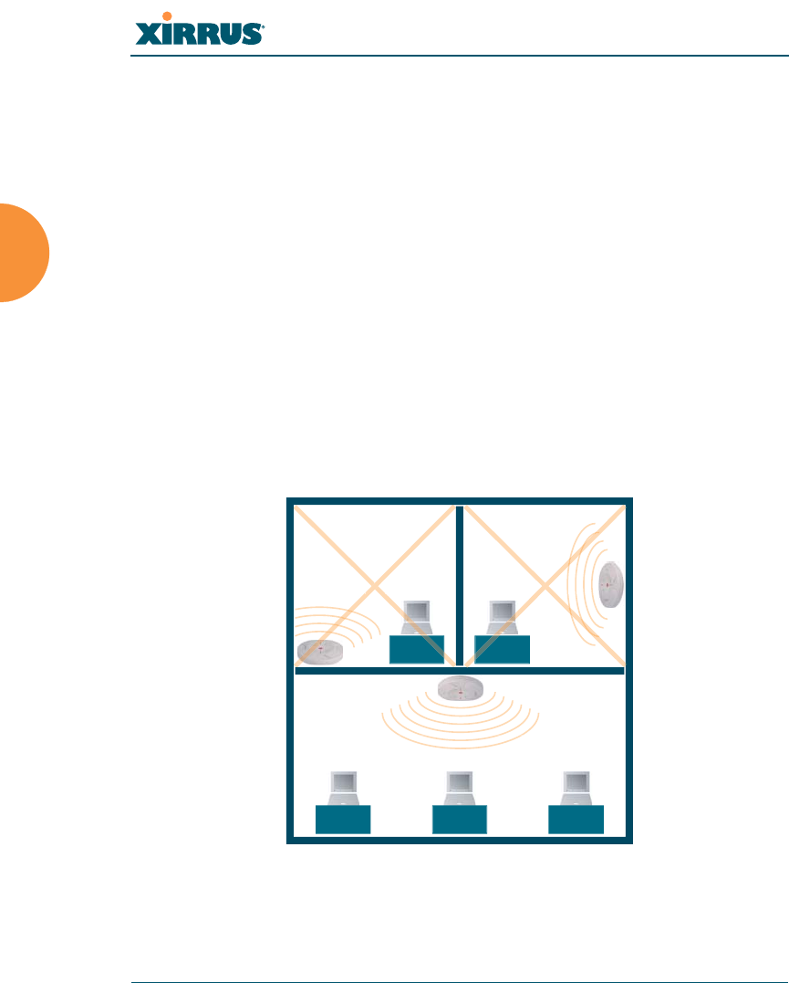
Wi-Fi Array
52 Installing the Wi-Fi Array
Installing Your Wi-Fi Array
This section provides instructions for completing a physical installation of your
Xirrus Wi-Fi Array.
Choosing a Location
Based on coverage, capacity and deployment examples previously discussed,
choose a location for the Array that will provide the best results for your needs.
The Wi-Fi Array was designed to be mounted on a ceiling where the unit is
unobtrusive and wireless transmissions can travel unimpeded throughout open
plan areas.
You also have the option of mounting the Array on a wall, using the optional wall
mount assembly kit. For wall mount instructions, go to “Mounting the Array on a
Wall (XN16/XN8)” on page 62.
Choose a location that is central to your users (see the following diagram for
correct placement.
Figure 26. Array Placement
WR
ONG
CORRECT
R
ORRE
R
ORREC
WR
ONG
G
G
O
ON
R
O
R
ON
ON
R
O
R
ON

Wi-Fi Array
Installing the Wi-Fi Array 53
Wiring Considerations
Unless you are using the Xirrus Power over Gigabit Ethernet modules (PoGE)
with an Array that supports PoGE, an AC power outlet must be available to the
Array. If you are using PoGE to distribute power, see “Power over Gigabit
Ethernet (PoGE) (Optional)” on page 10.
Once you have determined the best location for your Wi-Fi Array, you must run
cables to the location for the following services:
Power
One of the following options:
zNo power cable is required if using PoGE modules.
zDedicated AC power if PoGE is not in use. You must use a UL-
approved cord. Order the power cord from the Xirrus product
list—Xirrus supplies only UL-approved power cords.
Network
zGigabit 1—If using PoGE modules, the Cat 5e or Cat 6 cable from
the Gigabit Ethernet switch to the Array must be less than 100m
long. The Array must be connected to PoGE networks without
routing cabling to the outside plant, to ensure that cabling is not
exposed to lightning strikes or possible high voltage crossover.
zGigabit 2 (optional)
zFast Ethernet (optional)
zSerial cable— cable lengths up to 25’ per the RS-232 specification.
Important Notes About Network Connections
Read the following notes before making any network connections.
#When the unit’s IP address is unknown or a network connection has not
been established, the serial cable is used for connecting directly with the
Command Line Interface (CLI) via HyperTerminal. When a network
connection is established, the Array can be managed from any of the
available network connections, either Fast Ethernet, Gigabit 1 or Gigabit 2.

Wi-Fi Array
54 Installing the Wi-Fi Array
See Also
Failover Planning
Installation Prerequisites
Installation Workflow
Mounting the Wi-Fi Array on a Wall (XN4)
Mounting the Array on a Wall (XN16/XN8)
Mounting the Array on a Ceiling
Power over Gigabit Ethernet (PoGE) (Optional)
Unpacking the Wi-Fi Array
Mounting the Array on a Ceiling
Most offices have drop-down acoustical ceiling tiles set into a standard grid. The
Wi-Fi Array has been designed to enable mounting to a tiled ceiling via a
mounting plate and clamps that attach to the grid. Once the mounting plate is
attached, the Array simply rotates onto the plate (similar to a smoke detector).
Once the unit is mounted it can be removed and re-attached easily, without the
need for tools or modifications to the original installation.
This section assumes that you are mounting the Array to a tiled ceiling. If your
ceiling is not tiled, the mounting plate can be attached directly to the ceiling with
the screws and anchors provided (without using the tile grid mounting clamps).
!The Array’s Ethernet ports should be plugged into an Ethernet switch, not an
Ethernet hub—if a hub is used, we recommend that you connect only one
Ethernet port.
!The Gigabit1 Ethernet interface is the primary port for both data and
management traffic. If a single Ethernet connection is used, it must be
connected to the Gigabit1 Ethernet interface. See also, “Port Failover
Protection” on page 40.
The 10/100 Ethernet Port may be used for managing the Array out of band
from the Gigabit Ethernet ports. The 10/100 port will route only management
traffic, using a static route that may be configured for this interface. See
“interface” on page 273.
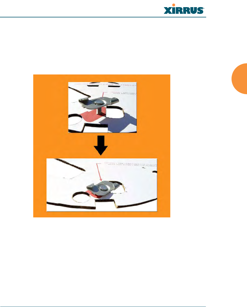
Wi-Fi Array
Installing the Wi-Fi Array 55
Attaching the T-Bar Clips to the Template
The T-bar clips are used to create four mounting points on the ceiling tile grid for
the Array mounting plate. Use the mounting template (provided) to find the
correct location for all four clamps by pre-loading the 4 T-bar clips through the
holes in the mounting template. Twist the clips until they are correctly aligned
with the markings on the template.
Figure 27. Attaching the T-Bar Clips to the Template
Secure the T-Bar Clips to the Ceiling Support Grid
The mounting template should be oriented so that the Array’s abg2 omni-
directional monitoring IAP (radio) is pointing in the direction of the least required
wireless signal coverage—for example, a nearby exterior wall or entrance.
Use the mounting template to find the correct location for all four T-bar clips, then
twist the clips onto the metal ceiling support grid and tighten the screw posts to
10-12 lbf.ft (1.38-1.66 kgf.m). See Figure 28. Do not overtighten the screw posts.
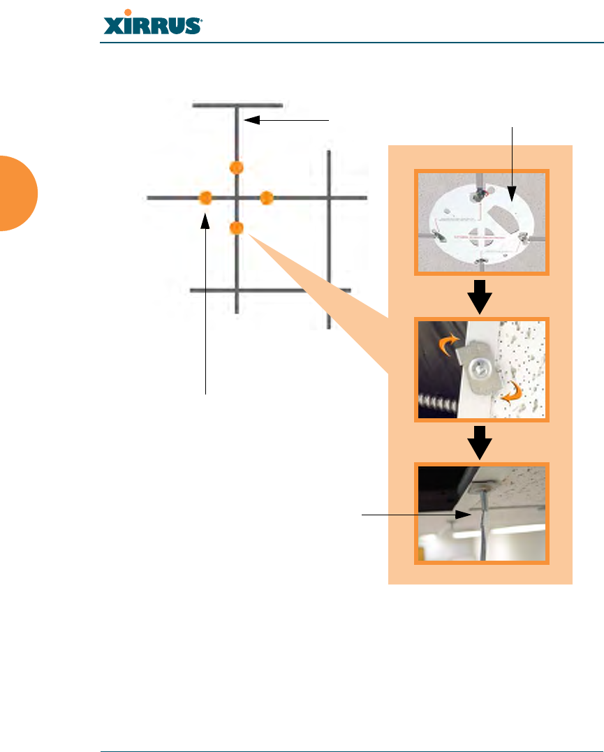
Wi-Fi Array
56 Installing the Wi-Fi Array
Disengage the template from the screw posts (4 places) and remove the template
from the ceiling.
Figure 28. Attaching the T-Bar Clips to the Ceiling Grid
Ceiling tile grid
T-bar clips (4 places)
Tighten the screw post
Template
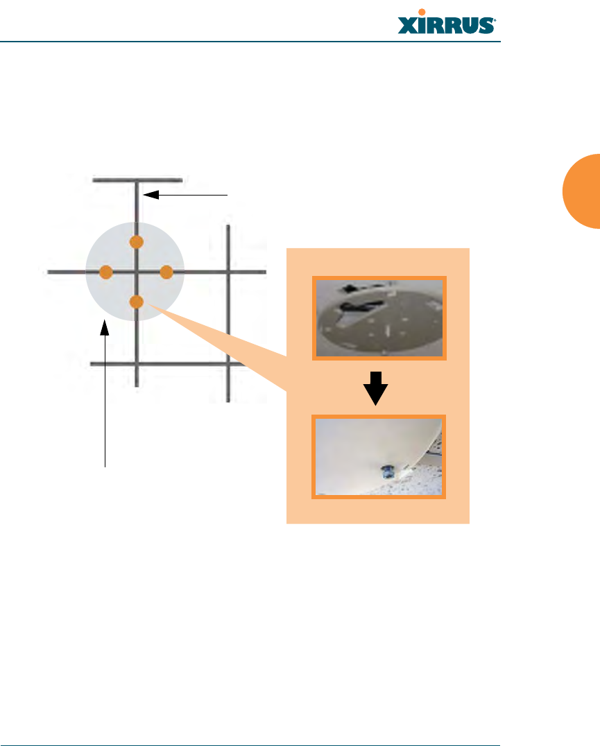
Wi-Fi Array
Installing the Wi-Fi Array 57
Installing the Mounting Plate
Locate the mounting plate on the four screw posts. Secure the plate to the four
clamps using the nuts provided. Tighten the nuts to 10-12 lbf.ft (1.38-1.66 kgf.m),
but do not overtighten.
Cut an access hole for the cables in the ceiling tile.
Figure 29. Installing the Mounting Plate
Tile grid
Mounting Plate
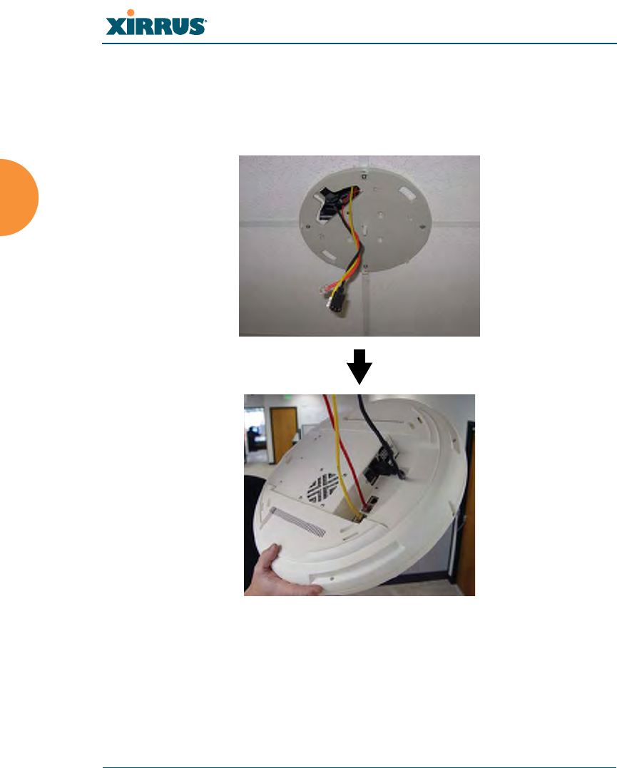
Wi-Fi Array
58 Installing the Wi-Fi Array
Connecting the Cables
Feed the power and Ethernet cables through the access hole in the tile and the
mounting plate, then connect the cables to the unit. See also, “Wiring
Considerations” on page 53.
Figure 30. Connecting the Cables
When the cables are connected, turn on the power switch—before attaching the
unit to the mounting plate (next step). Verify that the Ethernet link LED lights and
the LED boot sequence begins. The radio LEDs on the front of the unit will
illuminate in rotation, indicating that the Wi-Fi Array software is loading and the
unit is functioning correctly.
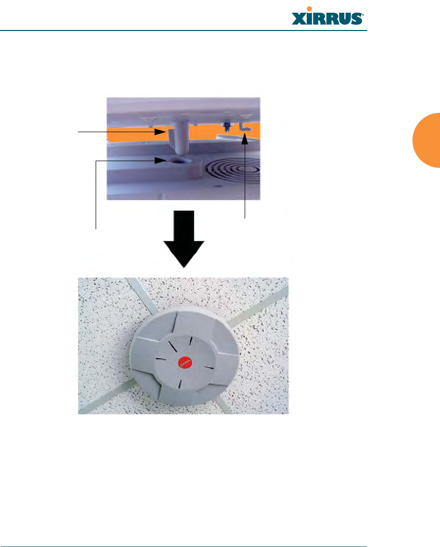
Wi-Fi Array
Installing the Wi-Fi Array 59
Attaching the Array to the Mounting Plate (XN16/XN8/XN4)
Align the Array with the key post on the mounting plate, then turn the Array to
the right to lock the unit into place at the 4 lugs—similar to a smoke detector.
Figure 31. Attaching the Unit (XN4)
See Also
Installation Workflow
Installing Your Wi-Fi Array
Mounting the Wi-Fi Array on a Wall (XN4)
Mounting the Array on a Wall (XN16/XN8)
Securing the Array
Key post
Lug
Alignment hole
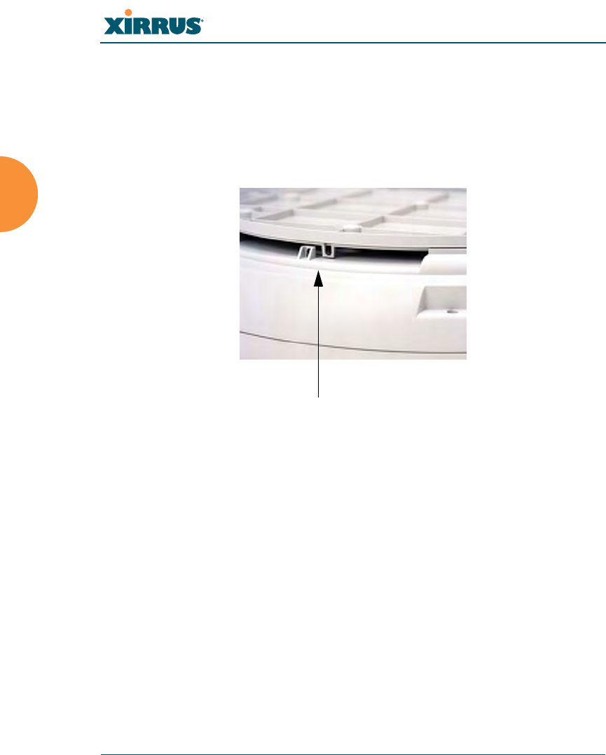
Wi-Fi Array
60 Installing the Wi-Fi Array
Securing the Array
For added security, there is a locking bracket incorporated into the mounting
plate, which will accept a small luggage-style padlock (if desired). There is also a
Kensington lock slot located near the Ethernet ports. In addition, the mounting
plate incorporates a positive locking tab that prevents the unit from being
inadvertently released.
Figure 32. Securing the Array
Now that the Array is physically installed, you must run the Express Setup
procedure from the unit’s Web Management Interface to enable the radios and
establish initial system configuration settings. Go to “Powering Up the Wi-Fi
Array” on page 73.
See Also
Installation Workflow
Installing Your Wi-Fi Array
Mounting the Wi-Fi Array on a Wall (XN4)
Mounting the Array on a Wall (XN16/XN8)
Mounting the Array on a Ceiling
Powering Up the Wi-Fi Array
Locking bracket

Wi-Fi Array
Installing the Wi-Fi Array 61
Dismounting the Array
To dismount the Array, place your fingers so as to increase the space between the
Array and the mounting plate at the positions indicated by the decals on the
mounting plate—these are aligned with IAPs (radios) abg1 and abg3, as indicated
on the clock-face of the Array.
Figure 33. IAP Positions (XN16)
See Also
Installation Workflow
Installing Your Wi-Fi Array
Mounting the Wi-Fi Array on a Wall (XN4)
Mounting the Array on a Wall (XN16/XN8)
Mounting the Array on a Ceiling
Securing the Array
a1
abg1
a2
a3
a4
abg2
a5
a6
a7
abg3
a8
a9
a10
abg4
a11
a12

Wi-Fi Array
62 Installing the Wi-Fi Array
Mounting the Array on a Wall (XN16/XN8)
This procedure is applicable to the Wi-Fi Array’s 16-radio models (XN16) and 8-
radio models (XN8). If you are mounting a 4 radio model, go to “Mounting the
Wi-Fi Array on a Wall (XN4)” on page 67.
The wall mounting assembly kit is used to mount the Wi-Fi Array (16-radio or
8-radio models) on a wall, instead of the traditional ceiling mount—if mounting
the Array on the ceiling is impractical at your location.
Kit Contents (Wall Mount Assembly - XN16 and XN8)
The wall mount assembly kit includes the following items:
z5 x SNAPTOGGLE™ toggle bolts (for attaching the wall bracket to the
wall)
z4 x 1/4 inch bolt assemblies (for attaching the mounting plate to the wall
bracket)
zWall Mounting Bracket
Tools Required
zPower drill
z1/2 inch (13mm) drill bit
zCross head screwdriver
z1/4 inch nut wrench
zPencil
zLevel

Wi-Fi Array
Installing the Wi-Fi Array 63
Mark the Wall Position
1. Use the Wall Mounting Bracket as a template and mark the locations on
the wall for the mounting holes.
Figure 34. Wall Mount—Marking the Holes
When marking the holes, ensure that the mounting plate is level—you
may need assistance.
#The bracket must be secured to the wall in 5 places, using the 2 holes at the
top and the 3 holes at the bottom (5 toggle bolts are provided).
Mark holes (5 places)