Cambium Networks XN8 Wireless LAN Array User Manual XN PDF
Xirrus, Inc. Wireless LAN Array XN PDF
Contents
Users Manual pt5of5
Wi-Fi Array
270 The Command Line Interface
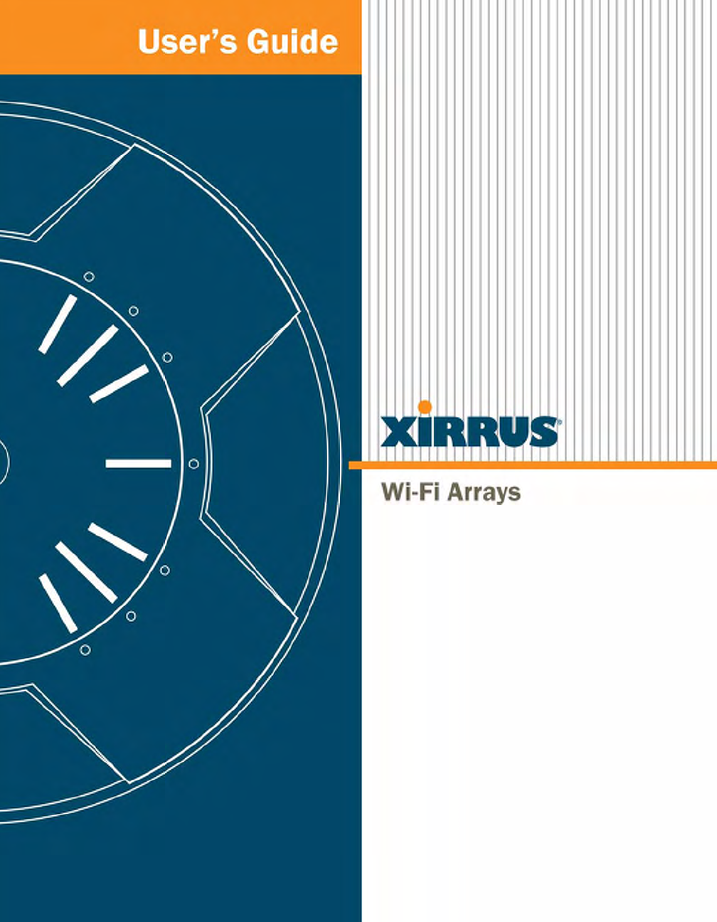
off Disable a filter list.
FORMAT:
filter off
on Enable a filter list.
FORMAT:
filter on
reset Delete all protocol filters and filter lists.
FORMAT:
filter reset
Command Description
Wi-Fi Array
The Command Line Interface 271
group
The group command [Xirrus_Wi-Fi_Array(config)# group] is used to create and
configure user groups. User groups allow administrators to assign specific
network parameters to users through RADIUS privileges rather than having to
map users to a specific SSID. Groups provide flexible control over user privileges
without the need to create large numbers of SSIDs. For more information, see
“Groups” on page 196.
hostname
The hostname command [Xirrus_Wi-Fi_Array(config)# hostname] is used to
change the hostname used by the Array.
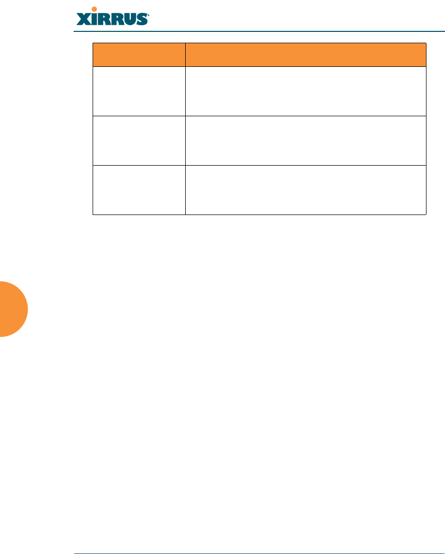
Command Description
add Create a new user group.
FORMAT:
group add [group-name]
del Delete a user group.
FORMAT:
group del [group-name]
edit Set parameters values for a group.
FORMAT:
group edit [group-name]
reset Reset the group.
FORMAT:
group reset
Command Description
hostname Change the hostname of the Array.
FORMAT:
hostname [name]
Wi-Fi Array
272 The Command Line Interface
https
The https command [Xirrus_Wi-Fi_Array(config)# https] is used to enable or
disable the Web Management Interface (https), which is enabled by default. It also
allows you to establish a timeout for your Web management session.
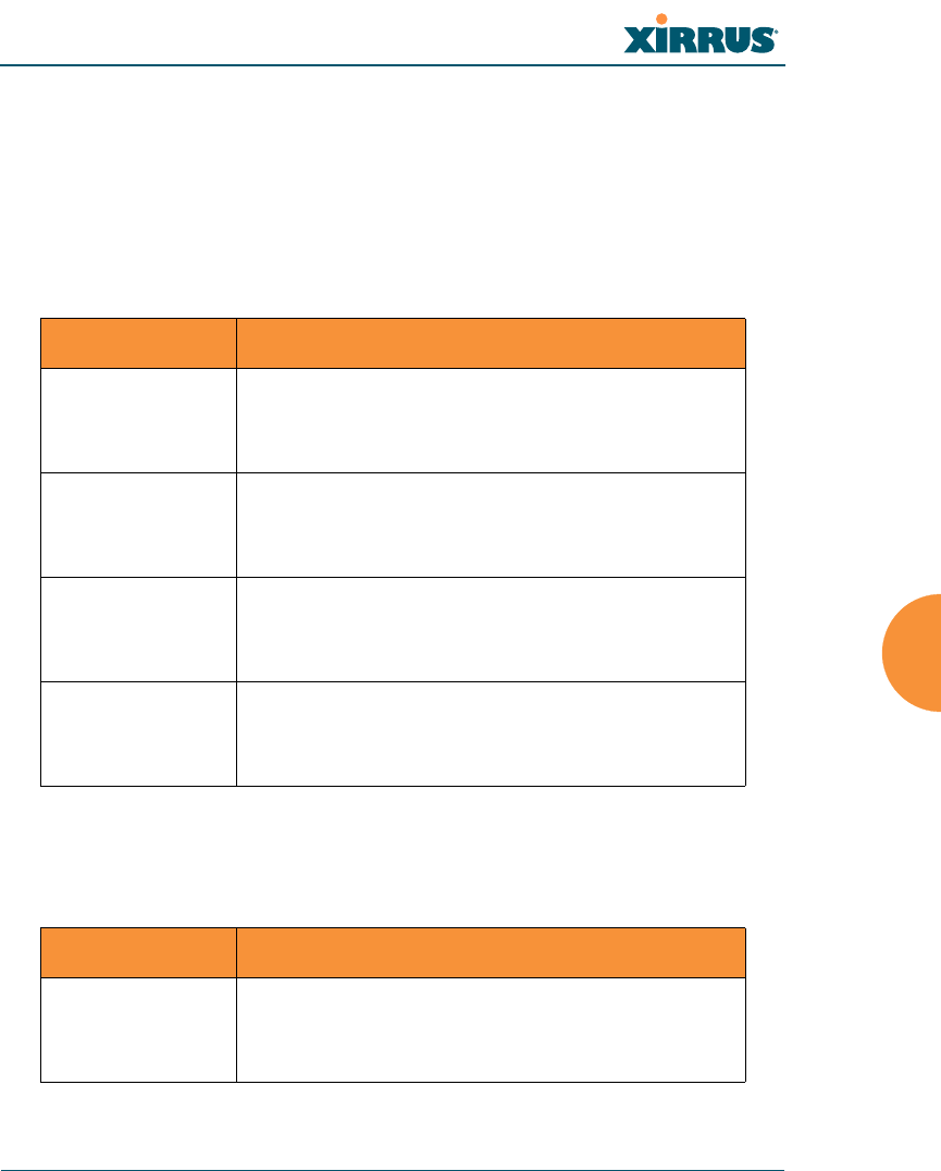
Command Description
disable Disable the https feature.
FORMAT:
https disable
enable Enable the https feature.
FORMAT:
https enable
off Disable the https feature.
FORMAT:
https off
on Enable the https feature.
FORMAT:
https on
timeout Define an elapsed period (in seconds) after which
the Web Management Interface will time out.
FORMAT:
https timeout 5000

Wi-Fi Array
The Command Line Interface 273
interface
The interface command [Xirrus_Wi-Fi_Array(config)# interface] is used to select
the interface that you want to configure. To see a listing of the commands that are
available for each interface, use the ? command at the selected interface prompt.
For example, using the ? command at the Xirrus_Wi-Fi_Array(config-gig1}#
prompt displays a listing of all commands for the gig1 interface.
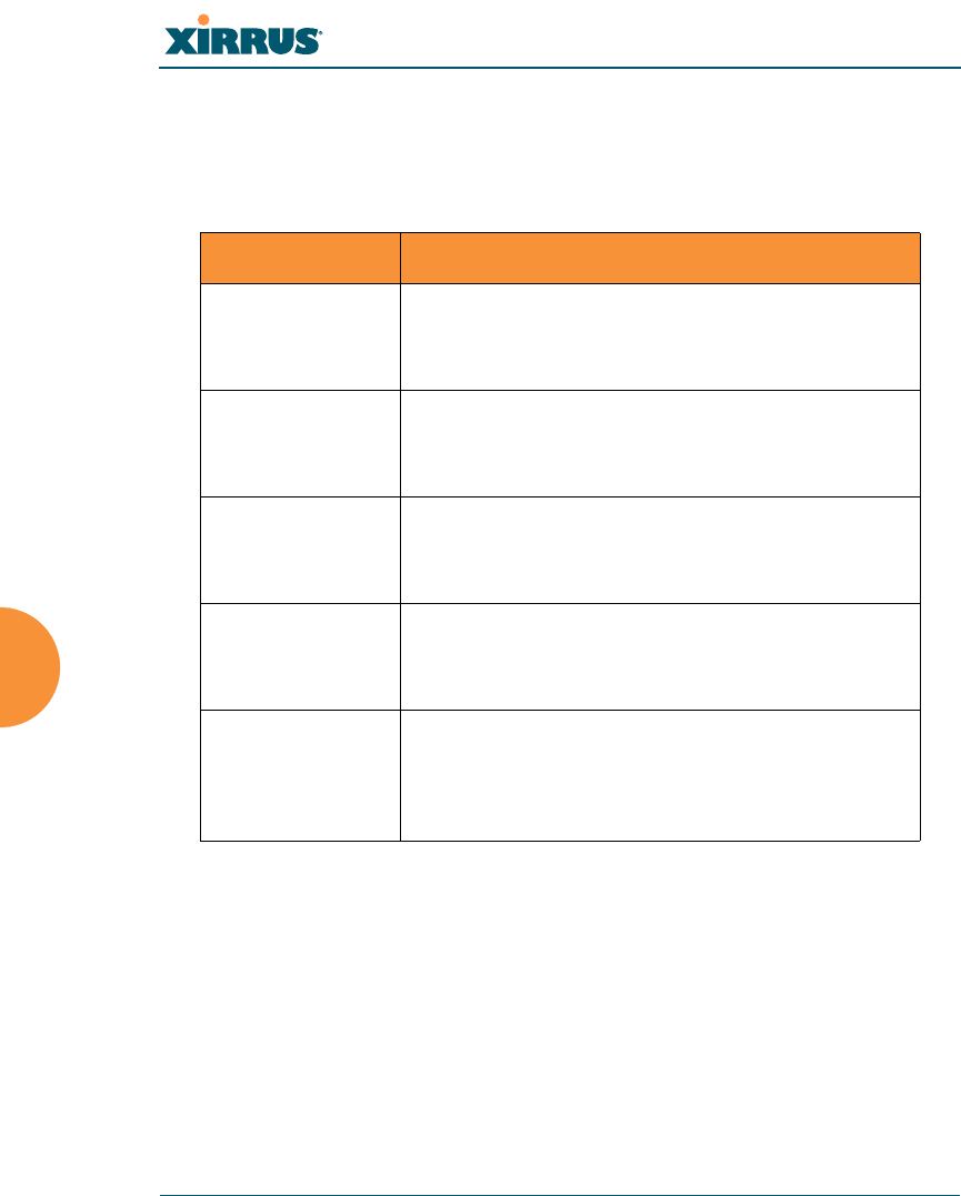
Command Description
console Select the console interface. The console interface
is used for management purposes only.
FORMAT:
interface console
eth0 Select the Fast Ethernet interface. The Fast
Ethernet interface is used for management
purposes only.
FORMAT:
interface eth0
Note: To configure a static route for management
traffic, next enter:
static-route addr [ip-addr]
static-route mask [subnet-mask]
gig1 Select the Gigabit 1 interface.
FORMAT:
interface gig1
gig2 Select the Gigabit 2 interface.
FORMAT:
interface gig2
iap Select an IAP.
FORMAT:
interface iap

Wi-Fi Array
274 The Command Line Interface
load
The load command [Xirrus_Wi-Fi_Array(config)# load] loads a configuration
file.
location
The location command [Xirrus_Wi-Fi_Array(config)# location] is used to set the
location for the Array.
Command Description
factory.conf Load the factory settings configuration file.
FORMAT:
load [factory.conf]
lastboot.conf Load the configuration file from the last boot-up.
FORMAT:
load [lastboot.conf]
[myfile].conf If you have saved a configuration, enter its name
to load it.
FORMAT:
load [myfile.conf]
saved.conf Load the configuration file with the last saved
settings.
FORMAT:
load [saved.conf]
Command Description
<cr> Set the location for the Array.
FORMAT:
location [newlocation]
When you enter the location, simply hit the Enter
key <cr> to input the new location.
Wi-Fi Array
The Command Line Interface 275
management
The management command [Xirrus_Wi-Fi_Array(config)# management] enters
management mode, where you may configure console management parameters.
more
The more command [Xirrus_Wi-Fi_Array(config)# more] is used to turn terminal
pagination ON or OFF.
Command Description
<cr> Enter management mode.
FORMAT:
management <cr>
Command Description
off Turn OFF terminal pagination.
FORMAT:
more off
on Turn ON terminal pagination.
FORMAT:
more on

Wi-Fi Array
276 The Command Line Interface
no
The no command [Xirrus_Wi-Fi_Array(config)# no] is used to disable a selected
element or set the element to its default value.
Command Description
acl Disable the Access Control List.
FORMAT:
no acl
dot11a Disable all 802.11an IAPs (radios).
FORMAT:
no dot11a
dot11bg Disable all 802.11bg IAPs (radios).
FORMAT:
no dot11bg
https Disable https access.
FORMAT:
no https
intrude-detect Disable intrusion detection.
FORMAT:
no intrude-detect
management Disable management on all Ethernet interfaces.
FORMAT:
no management
more Disable terminal pagination.
FORMAT:
no more
ntp Disable the NTP server.
FORMAT:
no ntp

Wi-Fi Array
The Command Line Interface 277
snmp Disable SNMP features.
FORMAT:
no snmp
ssh Disable ssh access.
FORMAT:
no ssh
syslog Disable the syslog services.
FORMAT:
no syslog
telnet Disable Telnet access.
FORMAT:
no telnet
ETH-NAME Disable the selected Ethernet interface (eth0, gig1
or gig2). You cannot disable the console interface.
with this command.
FORMAT:
no eth0 (gig1 or gig2)
Command Description

Wi-Fi Array
278 The Command Line Interface
quit
The quit command [Xirrus_Wi-Fi_Array(config)# quit] is used to exit the
Command Line Interface.
radius-server
The radius-server command [Xirrus_Wi-Fi_Array(config-radius-server)#] is
used to configure the external and internal RADIUS server parameters.
Command Description
<cr> Exit the Command Line Interface.
FORMAT:
quit
If you have made any configuration changes and
your changes have not been saved, you are
prompted to save your changes to Flash.
At the prompt, answer Yes to save your changes,
or answer No to discard your changes.
Command Description
external Configure the external RADIUS server.
FORMAT:
radius-server external
To configure the RADIUS accounting server
(primary or secondary, and the reporting interval)
use:
radius-server external accounting
internal Configure the external RADIUS server.
FORMAT:
radius-server internal
use Choose the active RADIUS server (either external
or internal).
FORMAT:
use external (or internal)

Wi-Fi Array
The Command Line Interface 279
reboot
The reboot command [Xirrus_Wi-Fi_Array(config)# reboot] is used to reboot the
Array. If you have unsaved changes, the command will notify you and give you a
chance to cancel the reboot.
reset
The reset command [Xirrus_Wi-Fi_Array(config)# reset] is used to reset all
settings to their default values then reboot the Array.
Command Description
<cr> Reboot the Array.
FORMAT:
reboot
delay Reboot the Array after a delay of 1 to 60 seconds.
FORMAT:
reboot delay [n]
Command Description
<cr> Reset all configuration parameters to their factory
default values.
FORMAT:
reset
The Array is rebooted automatically.
preserve-ip-
settings
Preserve all ethernet and VLAN settings and reset
all other configuration parameters to their factory
default values.
FORMAT:
reset preserve-ip-settings
The Array is rebooted automatically.

Wi-Fi Array
280 The Command Line Interface
run-tests
The run-tests command [Xirrus_Wi-Fi_Array(run-tests)#] is used to enter run-
tests mode, which allows you to perform a range of tests on the Array.
Command Description
<cr> Enter run-tests mode.
FORMAT:
run-tests
iperf Execute iperf utility.
FORMAT:
run-tests iperf
kill-beacons Turn off beacons for selected single IAP.
FORMAT:
run-tests kill-beacons [off | iap-name]
kill-probe-
responses
Turn off probe responses for selected single IAP.
FORMAT:
run-tests kill-probe-responses [off | iap-name]
led LED test.
FORMAT:
run-tests led [flash | rotate]
memtest Execute memory tests.
FORMAT:
run-tests memtest
ping Execute ping utility.
FORMAT:
run-tests ping [host-name | ip-addr]
rlb Run manufacturing radio loopback test.
FORMAT:
run-tests rlb {optional command line switches]

Wi-Fi Array
The Command Line Interface 281
self-test Execute self-test.
FORMAT:
run-tests self-test {logfile-name (optional)]
site-survey Enable or disable site survey mode.
FORMAT:
run-tests site-survey [on | off | enable | disable]
ssh Execute ssh utility.
FORMAT:
run-tests ssh [hostname | ip-addr]
[command-line-switches (optional)]
tcpdump Execute tcpdump utility to dump traffic for
selected interface or VLAN.
FORMAT:
run-tests tcpdump
telnet Execute telnet utility.
FORMAT:
run-tests telnet [hostname | ip-addr]
[command-line-switches (optional)]
traceroute Execute traceroute utility.
FORMAT:
run-tests traceroute [host-name | ip-addr]
Command Description
Wi-Fi Array
282 The Command Line Interface
security
The security command [Xirrus_Wi-Fi_Array(config-security)#] is used to
establish the security parameters for the Array.
Command Description
wep Set the WEP encryption parameters.
FORMAT:
security wep
wpa Set the WEP encryption parameters.
FORMAT:
security wpa

Wi-Fi Array
The Command Line Interface 283
snmp
The snmp command [Xirrus_Wi-Fi_Array(config-snmp)#] is used to enable,
disable, or configure SNMP.
Command Description
community Set the SNMP read-only or read-write community
string.
FORMAT:
snmp community [newcommunity]
disable Disable SNMP.
FORMAT:
snmp disable
enable Enable SNMP.
FORMAT:
snmp enable
no Disable the selected feature.
FORMAT:
snmp no [feature]
off Disable SNMP.
FORMAT:
snmp off
on Enable SNMP.
FORMAT:
snmp on
trap-auth Send traps for authentication failures.
FORMAT:
snmp trap-auth [trap]
trap-host[1-4] Set the SNMP trap IP address or host name. Up to
four trap hosts may be set, one at a time.
FORMAT:
snmp trap-host 1.2.3.4
Wi-Fi Array
284 The Command Line Interface
ssh
The ssh command [Xirrus_Wi-Fi_Array(config)# ssh] is used to enable or disable
the SSH feature.
trap-port[1-4] Set the SNMP trap port.
FORMAT:
snmp trap-port 240
Command Description
disable Disable SSH.
FORMAT:
ssh disable
enable Enable SSH.
FORMAT:
ssh enable
off Disable SSH.
FORMAT:
ssh off
on Enable SSH.
FORMAT:
ssh on
timeout Set the SSH inactivity timeout.
FORMAT:
ssh timeout 300 (in seconds)
Command Description

Wi-Fi Array
The Command Line Interface 285
ssid
The ssid command [Xirrus_Wi-Fi_Array(config-ssid)#] is used to establish your
SSID parameters.
standby
The standby command [Xirrus_Wi-Fi_Array(config-ssid)#] sets this Array to
function as a standby unit for another Array.
Command Description
add Add an SSID.
FORMAT:
ssid add [newssid]
del Delete an SSID.
FORMAT:
ssid del [oldssid]
edit Edit an existing SSID.
FORMAT:
ssid edit [existingssid]
reset Delete all SSIDs and restore the default SSID.
FORMAT:
ssid reset
Command Description
mode Enable or disable standby mode on this Array.
FORMAT:
standby mode [disable|enable|off|on]
target Specify the MAC address of the target Array to be
monitored for failure.
FORMAT:
standby target [AA:BB:CC:DD:EE:FF]

Wi-Fi Array
286 The Command Line Interface
syslog
The syslog command [Xirrus_Wi-Fi_Array(config-syslog)#] is used to enable,
disable, or configure the Syslog server.
Command Description
console Enable or disable the display of Syslog messages
on the console, and set the level to be displayed.
All messages at this level and lower (i.e., more
severe) will be displayed.
FORMAT:
syslog console [on/off] level [0-7]
disable Disable the Syslog server.
FORMAT:
syslog disable
email Disable the Syslog server.
FORMAT:
syslog email from [email-from-address]
level [0-7]
password [email-acct-password]
server [email-server-IPaddr]
test [test-msg-text]
to-list [recipient-email-addresses]
user [email-acct-username]
enable Enable the Syslog server.
FORMAT:
syslog enable
local-file Set the size and/or severity level (all messages at
this level and lower will be logged).
FORMAT:
syslog local-file size [1-500] level [0-7]
no Disable the selected feature.
FORMAT:
syslog no [feature]

Wi-Fi Array
The Command Line Interface 287
telnet
The telnet command [Xirrus_Wi-Fi_Array(config)# telnet] is used to enable or
disable Telnet.
off Disable the Syslog server.
FORMAT:
syslog off
on Enable the Syslog server.
FORMAT:
syslog on
primary Set the IP address of the primary Syslog server
and/or the severity level of messages to be
logged.
FORMAT:
syslog primary [1.2.3.4] level [0-7]
secondary Set the IP address of the secondary (backup)
Syslog server and/or the severity level of
messages to be logged.
FORMAT:
syslog primary [1.2.3.4] level [0-7]
Command Description
disable Disable Telnet.
FORMAT:
telnet disable
enable Enable Telnet.
FORMAT:
telnet enable
Command Description

Wi-Fi Array
288 The Command Line Interface
off Disable Telnet.
FORMAT:
telnet off
on Enable Telnet.
FORMAT:
telnet on
timeout Set the Telnet inactivity timeout.
FORMAT:
telnet timeout 300 (in seconds)
Command Description

Wi-Fi Array
The Command Line Interface 289
uptime
The uptime command [Xirrus_Wi-Fi_Array(config)# uptime] is used to display
the elapsed time since you last rebooted the Array.
vlan
The vlan command [Xirrus_Wi-Fi_Array(config-vlan)#] is used to establish your
VLAN parameters.
Command Description
<cr> Display time since last reboot.
FORMAT:
uptime
Command Description
add Add a VLAN.
FORMAT:
vlan add [newvlan]
default-route Assign a VLAN for the default route (for
outbound management traffic).
FORMAT:
vlan default-route [defaultroute]
delete Delete a VLAN.
FORMAT:
vlan delete [oldvlan]
edit Modify an existing VLAN.
FORMAT:
vlan edit [existingvlan]
native-vlan Assign a native VLAN (traffic is untagged).
FORMAT:
vlan native-vlan [nativevlan]

Wi-Fi Array
290 The Command Line Interface
no Disable the selected feature.
FORMAT:
vlan no [feature]
reset Delete all existing VLANs.
FORMAT:
vlan reset
Command Description

Wi-Fi Array
The Command Line Interface 291
Sample Configuration Tasks
This section provides examples of some of the common configuration tasks used
with the Wi-Fi Array, including:
z“Configuring a Simple Open Global SSID” on page 292.
z“Configuring a Global SSID using WPA-PEAP” on page 293.
z“Configuring an SSID-Specific SSID using WPA-PEAP” on page 294.
z“Enabling Global IAPs” on page 295.
z“Disabling Global IAPs” on page 296.
z“Enabling a Specific IAP” on page 297.
z“Disabling a Specific IAP” on page 298.
z“Setting Cell Size Auto-Configuration for All IAPs” on page 299
z“Setting the Cell Size for All IAPs” on page 300.
z“Setting the Cell Size for a Specific IAP” on page 301.
z“Configuring VLANs on an Open SSID” on page 302.
z“Configuring Self-Monitoring Mode (Loopback Tests)” on page 303.
To facilitate the accurate and timely management of revisions to this section, the
examples shown here are presented as screen images taken from a Secure Shell
(SSH) session (in this case, PuTTY). Depending on the application you are using
to access the Command Line Interface, and how your session is set up (for
example, font and screen size), the images presented on your screen may be
different than the images shown in this section. However, the data displayed will
be the same.
Some of the screen images shown in this section have been modified for clarity.
For example, the image may have been “elongated” to show all data without the
need for additional images or scrolling. We recommend that you use the Adobe
PDF version of this User’s Guide when reviewing these examples—a hard copy
document may be difficult to read.
As mentioned previously, the root command prompt is determined by the host
name assigned to your Array.
Wi-Fi Array
292 The Command Line Interface
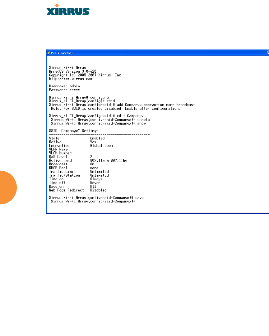
Configuring a Simple Open Global SSID
This example shows you how to configure a simple open global SSID.
Figure 142. Configuring a Simple Open Global SSID
Wi-Fi Array
The Command Line Interface 293
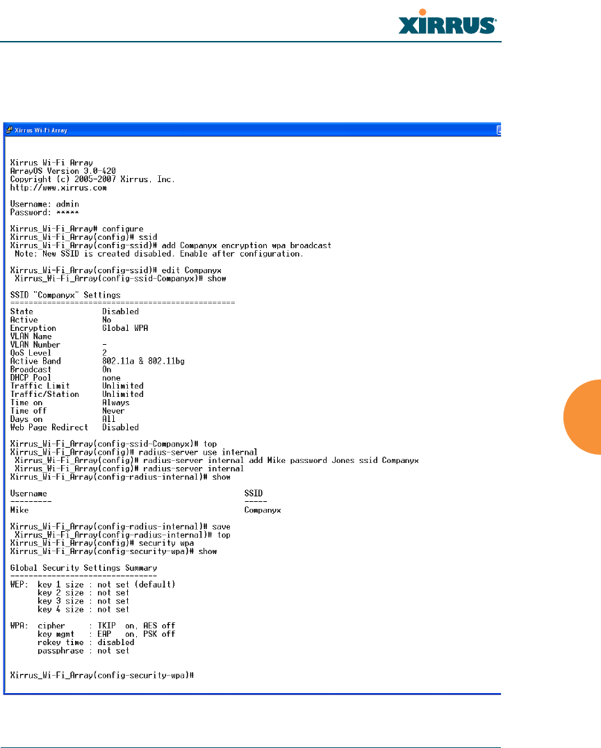
Configuring a Global SSID using WPA-PEAP
This example shows you how to configure a global SSID using WPA-PEAP
encryption in conjunction with the Array’s Internal RADIUS server.
Figure 143. Configuring a Global SSID using WPA-PEAP
Wi-Fi Array
294 The Command Line Interface
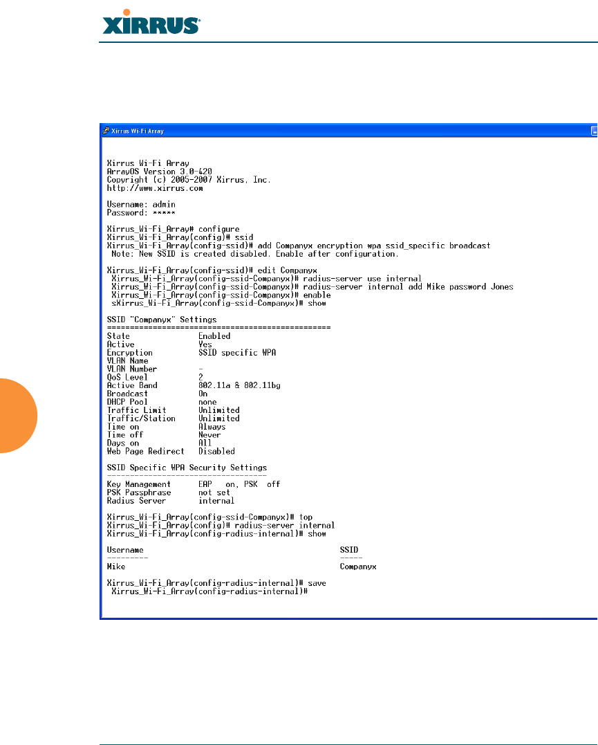
Configuring an SSID-Specific SSID using WPA-PEAP
This example shows you how to configure an SSID-specific SSID using WPA-
PEAP encryption in conjunction with the Array’s Internal RADIUS server.
Figure 144. Configuring an SSID-Specific SSID using WPA-PEAP
Wi-Fi Array
The Command Line Interface 295
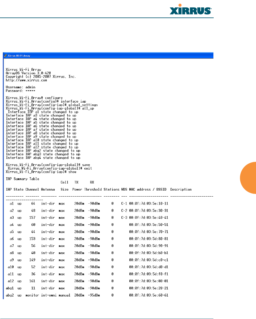
Enabling Global IAPs
This example shows you how to enable all IAPs (radios), regardless of the
wireless technology they use.
Figure 145. Enabling Global IAPs
Wi-Fi Array
296 The Command Line Interface
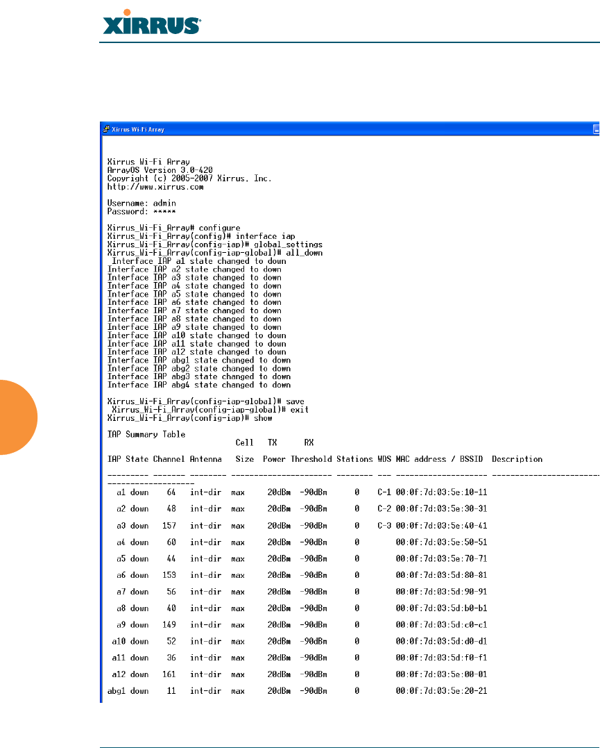
Disabling Global IAPs
This example shows you how to disable all IAPs (radios), regardless of the
wireless technology they use.
Figure 146. Disabling Global IAPs
Wi-Fi Array
The Command Line Interface 297
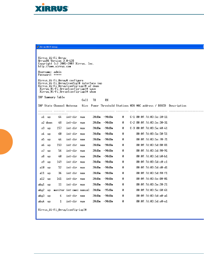
Enabling a Specific IAP
This example shows you how to enable a specific IAP (radio). In this example, the
IAP that is being enabled is a1 (the first IAP in the summary list).
Figure 147. Enabling a Specific IAP
Wi-Fi Array
298 The Command Line Interface
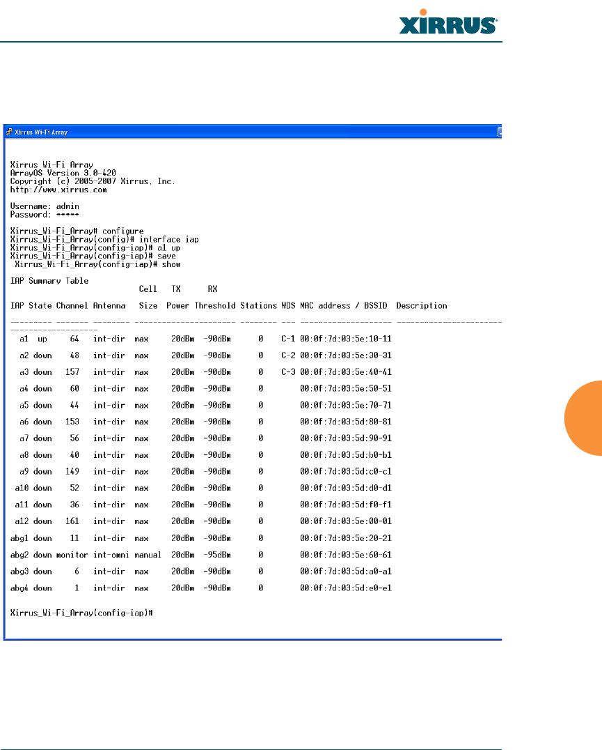
Disabling a Specific IAP
This example shows you how to disable a specific IAP (radio). In this example,
the IAP that is being disabled is a2 (the second IAP in the summary list).
Figure 148. Disabling a Specific IAP
Wi-Fi Array
The Command Line Interface 299
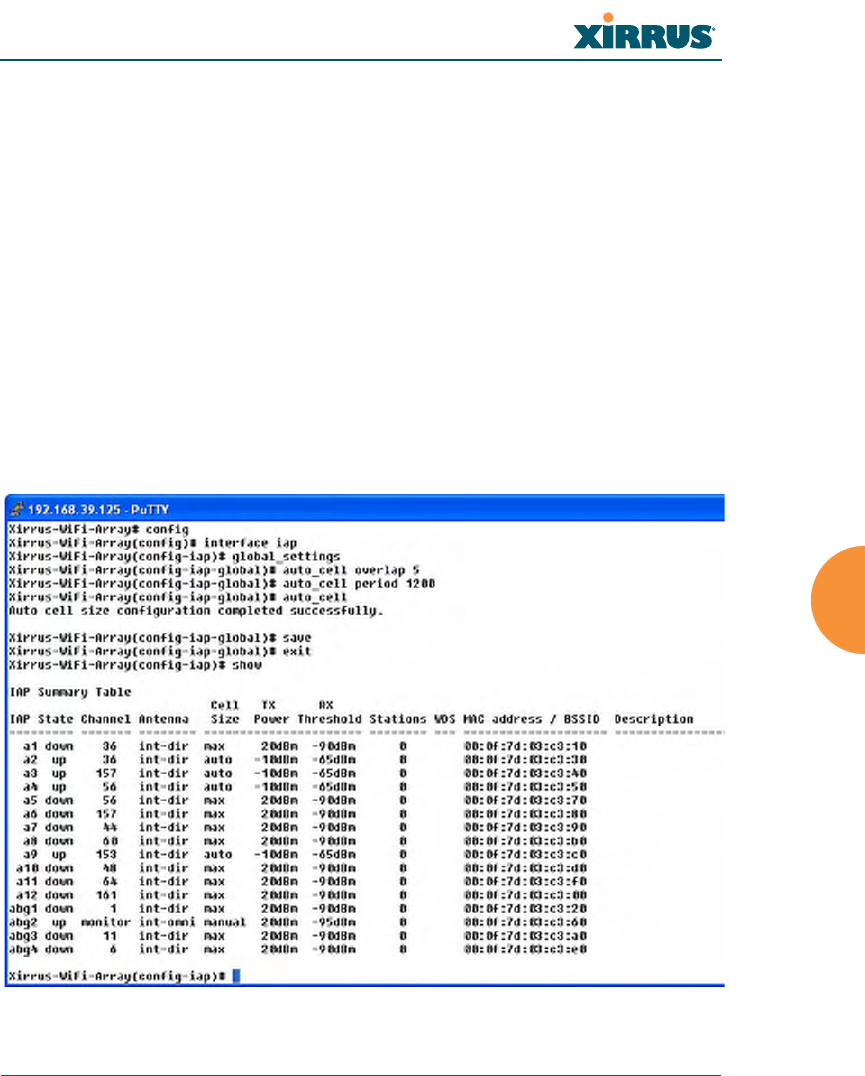
Setting Cell Size Auto-Configuration for All IAPs
This example shows how to set the cell size for all enabled IAPs to be auto-
configured (auto). (See “Fine Tuning Cell Sizes” on page 35.) The auto_cell option
may be used with global_settings, global_a_settings, or global_bg_settings. It
sets the cell size of the specified IAPs to auto, and it launches an auto-
configuration to adjust the sizes. Be aware that if the intrude-detect feature is
enabled on abg2, its cell size is unaffected by this command. Also, any IAPs used
in WDS links are unaffected.
Auto-configuration may be set to run periodically at intervals specified by
auto_cell period (in seconds) if period is non-zero. The percentage of overlap
allowed between cells in the cell size computation is specified by auto_cell
overlap (0 to 100). This example sets auto-configuration to run every 1200 seconds
with an allowed overlap of 5%. It sets the cell size of all IAPs to auto, and runs a
cell size auto-configure operation which completes successfully.
Figure 149. Setting the Cell Size for All IAPs
Wi-Fi Array
300 The Command Line Interface
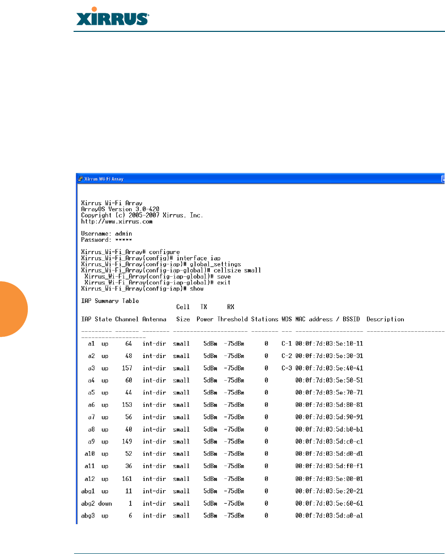
Setting the Cell Size for All IAPs
This example shows you how to establish the cell size for all IAPs (radios),
regardless of the wireless technology they use. Be aware that if the intrude-detect
feature is enabled on abg2 the cell size cannot be set globally—you must first
disable the intrude-detect feature on abg2.
In this example, the cell size is being set to small for all IAPs. You have the option
of setting IAP cell sizes to small, medium, large, or max. See also, “Fine Tuning
Cell Sizes” on page 35.
Figure 150. Setting the Cell Size for All IAPs
Wi-Fi Array
The Command Line Interface 301
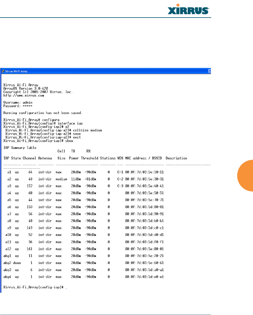
Setting the Cell Size for a Specific IAP
This example shows you how to establish the cell size for a specific IAP (radio). In
this example, the cell size for a2 is being set to medium. You have the option of
setting IAP cell sizes to small, medium, large, or max (the default is max). See
also, “Fine Tuning Cell Sizes” on page 35.
Figure 151. Setting the Cell Size for a Specific IAP
Wi-Fi Array
302 The Command Line Interface
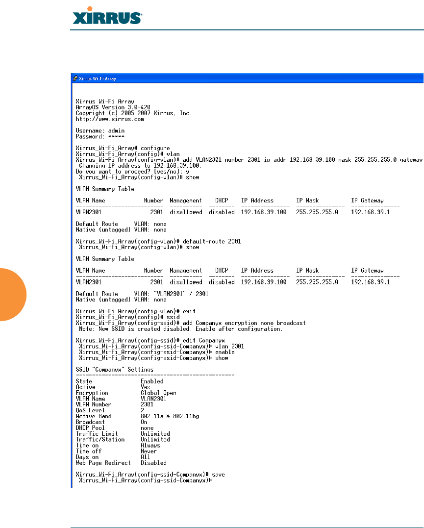
Configuring VLANs on an Open SSID
This example shows you how to configure VLANs on an Open SSID.
Figure 152. Configuring VLANs on an Open SSID
#Setting the default route
enables the Array to send
management traffic, such as
syslog messages and SNMP
information to a destination
behind a router.

Wi-Fi Array
The Command Line Interface 303
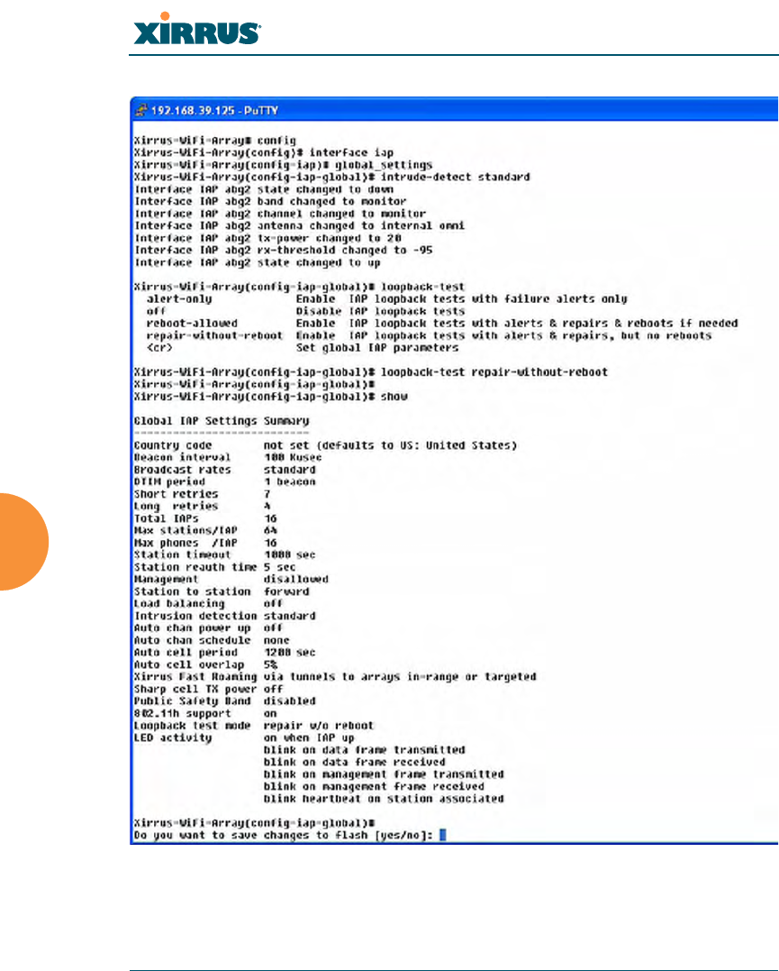
Configuring Self-Monitoring Mode (Loopback Tests)
The Array uses the built-in monitor radio (IAP abg2) to monitor other radios in
the Array. Tests include sending probes on all channels and checking for a
response, and checking whether beacons are received from the other radio. If a
problem is detected, corrective actions are taken to recover. Loopback mode
operation is described in detail in “Array Monitor and Loopback Testing
Capabilities” on page 341.
The following actions may be configured:
zalert-only—the Array will issue an alert in the Syslog.
zrepair-without-reboot—the Array will issue an alert and reset radios at
the Physical Layer (Layer 1) and possibly at the MAC layer. The reset
should not be noticed by users, and they will not need to reassociate.
zreboot-allowed—the Array will issue an alert, reset the radios, and
schedule the Array to reboot at midnight (per local Array time) if
necessary. All stations will need to reassociate to the Array.
zoff—Disable IAP loopback tests (no self-monitoring occurs). Loopback
tests are off by default.
This is a global IAPs setting—abg2 will monitor all other radios according to the
settings above, and it cannot be set up to monitor particular radios. Self-
monitoring mode requires Intrusion Detection to be set to Standard.
The following example shows you how to configure a loopback test.
Wi-Fi Array
304 The Command Line Interface
Figure 153. Configuring a Loopback Test

Wi-Fi Array
305
Appendices

Wi-Fi Array
306
Page is intentionally blank
Wi-Fi Array
Appendix A: Servicing the Wi-Fi Array 307
Appendix A: Servicing the Wi-Fi Array
This appendix contains procedures for servicing the Xirrus Wi-Fi Array, including
the removal and reinstallation of major hardware components. Topics include:
z“Removing the Access Panel” on page 309.
z“Reinstalling the Access Panel” on page 312.
z“Replacing the FLASH Memory Module” on page 314.
z“Replacing the Main System Memory” on page 316.
z“Replacing the Integrated Access Point Radio Module” on page 318.
z“Replacing the Power Supply Module” on page 321.
!
!
!
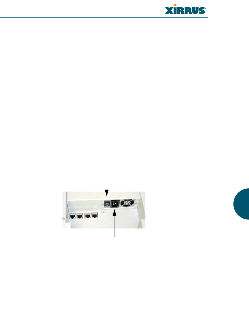
Always turn OFF the Array’s power switch and disconnect the AC power cord
before attempting to remove or replace components. Never work on the unit
with the power connected.
You must be grounded and the work surface must be static-free.
Caution! The Array contains a battery which is not to be replaced by the
customer. Danger of Explosion exists if the battery is incorrectly replaced.
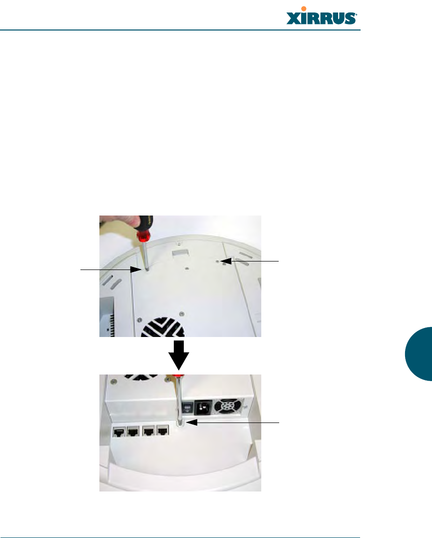
Figure 154. Disconnecting Power from the Array
#Most service activities are performed with the Array placed face-down on a
flat work surface. To avoid damaging the finished enclosure, we recommend
using a protective material between the work surface and the unit (a clean
sheet of paper will do the trick).
Power switch
AC power cord receptacle

Wi-Fi Array
308 Appendix A: Servicing the Wi-Fi Array
See Also
Reinstalling the Access Panel
Removing the Access Panel
Replacing the FLASH Memory Module
Replacing the Integrated Access Point Radio Module
Replacing the Main System Memory
Replacing the Power Supply Module
Wi-Fi Array
Appendix A: Servicing the Wi-Fi Array 309
Removing the Access Panel
Use this procedure when you want to remove the system’s access panel. You must
remove this panel whenever you need to service the internal components of the
Array.
1. Turn OFF the Array’s main power switch (XN16 and XN8 only).
2. Disconnect the AC power cord from the Array.
3. Place the Array face-down on a flat surface. Avoid moving the unit to
reduce the risk of damage (scratching) to the finished enclosure.
4. Remove the screws (3 places) that secure the access panel to the main
body of the Array.
Figure 155. Removing the Access Panel Screws
Screw
Screw
Screw
Wi-Fi Array
310 Appendix A: Servicing the Wi-Fi Array
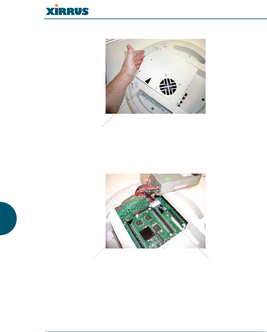
5. Lift up the access panel to reveal the main system board.
Figure 156. Removing the Access Panel
6. Disconnect the connectors to the power supply and the fan.
Figure 157. Disconnecting the Power Supply and Fan
7. The access panel can now be safely removed.
Lift up the access panel
Power supply connectorFan connector

Wi-Fi Array
Appendix A: Servicing the Wi-Fi Array 311
See Also
Reinstalling the Access Panel
Replacing the FLASH Memory Module
Replacing the Integrated Access Point Radio Module
Replacing the Main System Memory
Replacing the Power Supply Module
Appendix A: Servicing the Wi-Fi Array
Wi-Fi Array
312 Appendix A: Servicing the Wi-Fi Array
Reinstalling the Access Panel
Use this procedure when you need to reinstall the access panel after servicing the
Array’s internal components.
1. Reconnect the fan and power supply.
Figure 158. Reconnecting the Fan and Power Supply
2. Reinstall the access panel and secure the panel with the three screws.
Figure 159. Reinstalling the Access Panel
3. Reconnect the AC power cord and turn ON the main power switch.
Power supply connectorFan connector
Screw
!Do not
overtighten
Screw
!Do not
overtighten
Screw
!Do not
overtighten

Wi-Fi Array
Appendix A: Servicing the Wi-Fi Array 313
See Also
Removing the Access Panel
Replacing the FLASH Memory Module
Replacing the Integrated Access Point Radio Module
Replacing the Main System Memory
Replacing the Power Supply Module
Appendix A: Servicing the Wi-Fi Array
Wi-Fi Array
314 Appendix A: Servicing the Wi-Fi Array
Replacing the FLASH Memory Module
Use this procedure when you want to replace the system’s FLASH memory
module.
1. Remove the system’s access panel. Refer to “Removing the Access Panel”
on page 309.
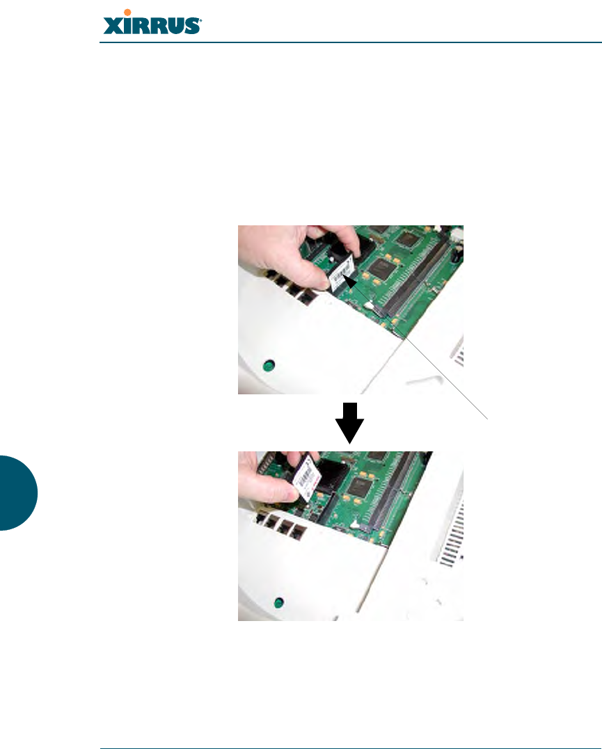
2. Remove the FLASH memory module, taking care not to “wiggle” the
module and risk damaging the connection points.
Figure 160. Removing the FLASH Memory Module
3. The removal procedure is complete. You can now reinstall the FLASH
memory module (or install a new module).
FLASH memory module

Wi-Fi Array
Appendix A: Servicing the Wi-Fi Array 315
4. Reinstall the access panel (refer to “Reinstalling the Access Panel” on
page 312).
See Also
Reinstalling the Access Panel
Removing the Access Panel
Replacing the Integrated Access Point Radio Module
Replacing the Main System Memory
Replacing the Power Supply Module
Appendix A: Servicing the Wi-Fi Array
Wi-Fi Array
316 Appendix A: Servicing the Wi-Fi Array
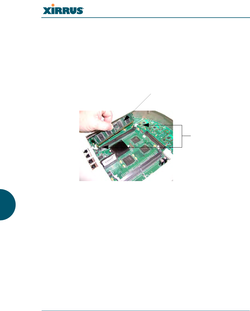
Replacing the Main System Memory
Use this procedure when you want to replace the main system memory.
1. Remove the access panel (refer to “Removing the Access Panel” on
page 309).
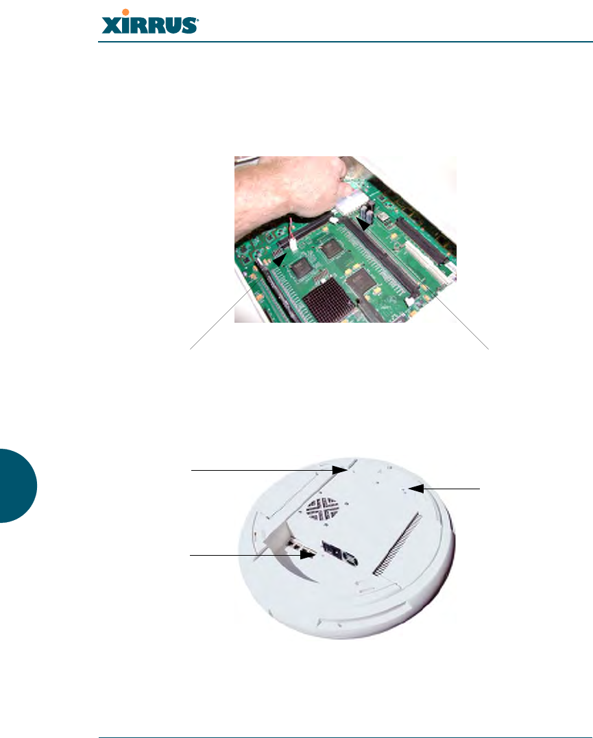
2. Remove the DIMM memory module, taking care not to “wiggle” the
module and risk damaging the connection points.
Figure 161. Removing the DIMM Memory Module
3. The removal procedure is complete. You can now reinstall the DIMM
memory module (or install a new module). Ensure that the DIMM
memory module is seated evenly and the locking tabs are in the upright
position. The DIMM memory module is keyed to fit in its socket in one
direction only.
4. Reinstall the access panel (refer to “Reinstalling the Access Panel” on
page 312).
See Also
Reinstalling the Access Panel
Removing the Access Panel
Replacing the FLASH Memory Module
DIMM memory module
Push down on
the two locking
tabs to release
the DIMM
memory module

Wi-Fi Array
Appendix A: Servicing the Wi-Fi Array 317
Replacing the Integrated Access Point Radio Module
Replacing the Power Supply Module
Appendix A: Servicing the Wi-Fi Array
Wi-Fi Array
318 Appendix A: Servicing the Wi-Fi Array
Replacing the Integrated Access Point Radio Module
Use this procedure when you want to replace the integrated access point radio
module.
1. Remove the access panel (refer to “Removing the Access Panel” on
page 309).
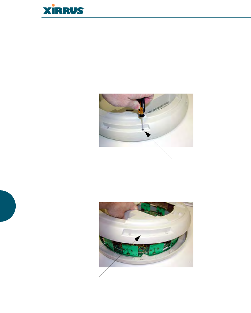
2. Remove the locking screws (8 places) that secure the chassis cover to the
main body of the Wi-Fi Array.
Figure 162. Removing the Chassis Cover Screws
3. Lift and remove the chassis cover.
Figure 163. Removing the Chassis Cover
Screws (8 places)
Remove the chassis cover
Wi-Fi Array
Appendix A: Servicing the Wi-Fi Array 319
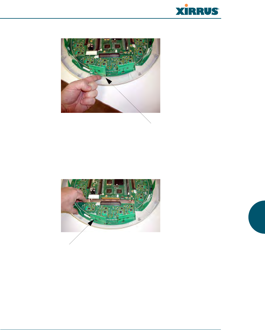
4. Lift the edge of the integrated access point module.
Figure 164. Lifting the Integrated Access Point Module
5. Slide the integrated access point module away from the unit to disconnect
it from the main system board.
Figure 165. Disconnect the Integrated Access Point Module
6. The removal procedure is complete. You can now reinstall the integrated
access point module (or install a new module).
Lift here (do not force)
Disconnect the module

Wi-Fi Array
320 Appendix A: Servicing the Wi-Fi Array
7. Reinstall the chassis cover (see warnings).
8. Reinstall the locking screws (8 places) to secure the chassis cover in
place—do not overtighten.
9. Reinstall the access panel (refer to “Reinstalling the Access Panel” on
page 312).
See Also
Reinstalling the Access Panel
Removing the Access Panel
Replacing the FLASH Memory Module
Replacing the Main System Memory
Replacing the Power Supply Module
Appendix A: Servicing the Wi-Fi Array
!
!
When reinstalling the chassis cover, take care to align the cover correctly to
avoid damaging the antenna modules. Do not force the chassis cover onto the
body of the unit.
Do not overtighten the locking screws.
Wi-Fi Array
Appendix A: Servicing the Wi-Fi Array 321
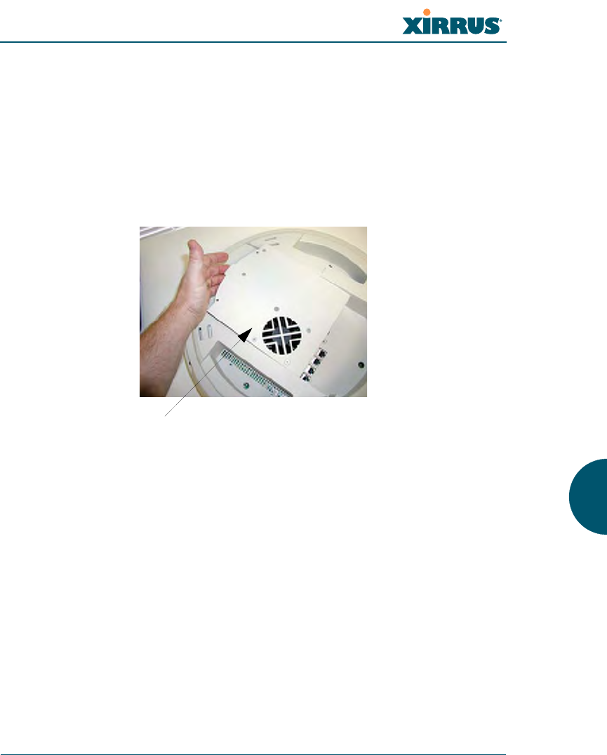
Replacing the Power Supply Module
Use this procedure when you want to replace the power supply module.
1. Remove the access panel (refer to “Removing the Access Panel” on
page 309).
2. Because the power supply unit is molded into the access panel, you must
install a new access panel assembly (with the power supply attached).
Refer to “Reinstalling the Access Panel” on page 312.
Figure 166. Installing a New Access Panel (with Power Supply)
See Also
Reinstalling the Access Panel
Removing the Access Panel
Replacing the FLASH Memory Module
Replacing the Integrated Access Point Radio Module
Replacing the Main System Memory
Appendix A: Servicing the Wi-Fi Array
Access panel (with power supply and fan)

Wi-Fi Array
322 Appendix A: Servicing the Wi-Fi Array
Use this Space for Your Notes
Wi-Fi Array
Appendix B: Quick Reference Guide 323
Appendix B: Quick Reference Guide
This section contains product reference information. Use this section to locate the
information you need quickly and efficiently. Topics include:
z“Factory Default Settings” on page 323.
Factory Default Settings
The following tables show the Wi-Fi Array’s factory default settings.
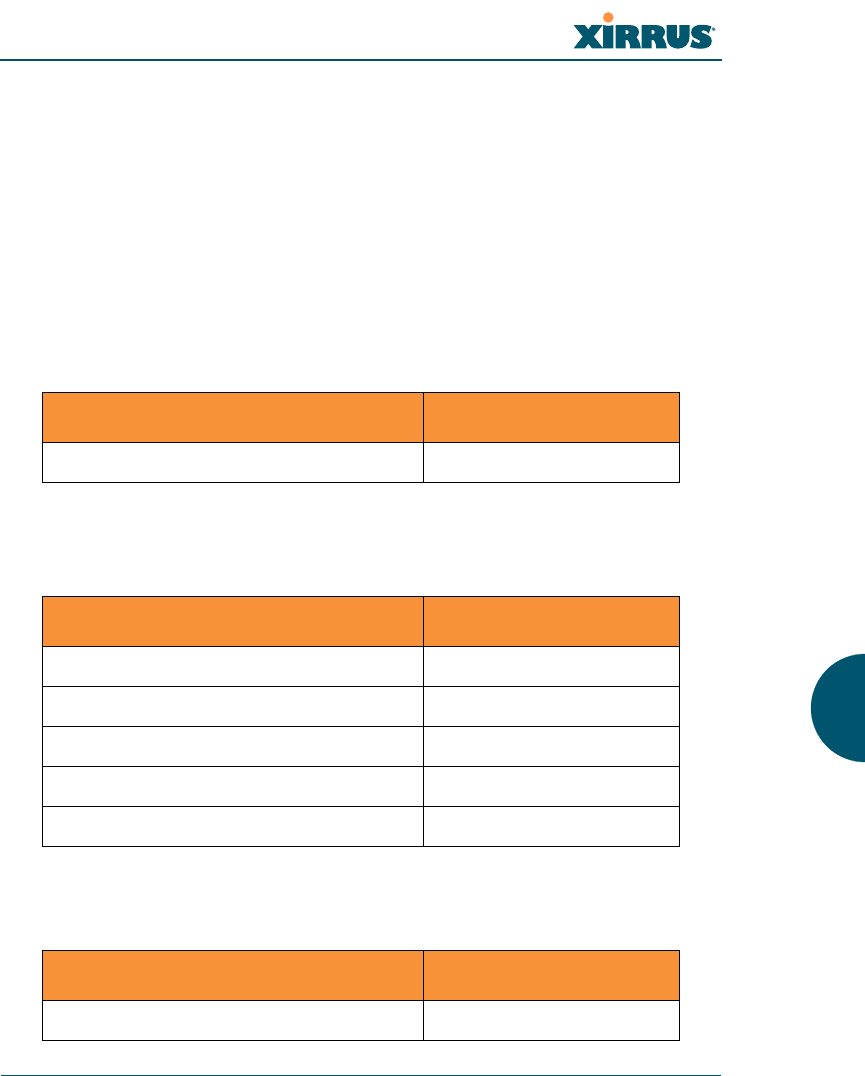
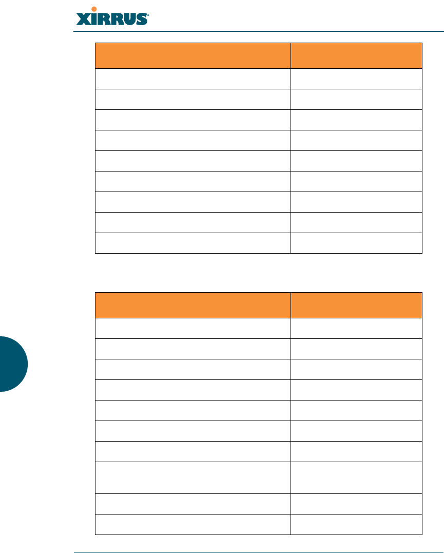
Host Name
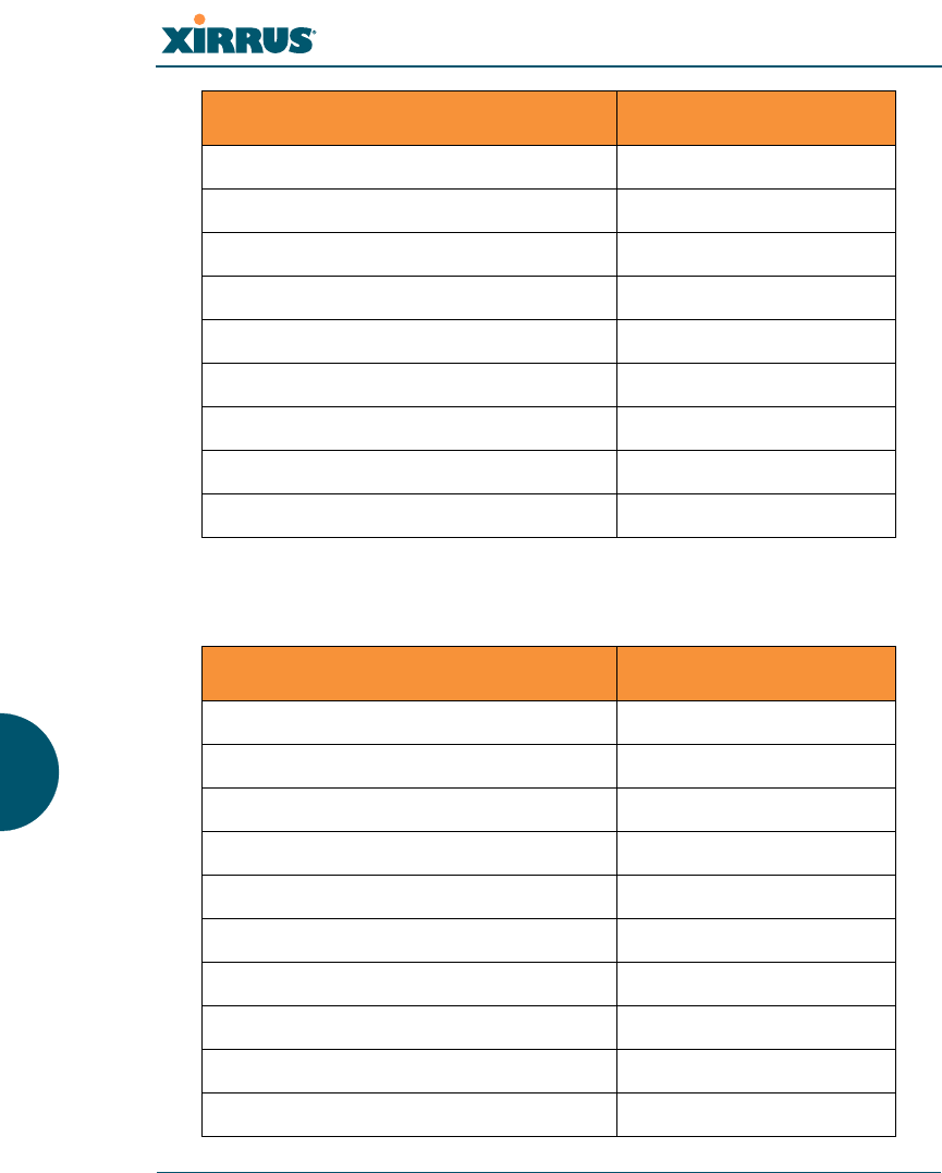
Network Interfaces
Serial
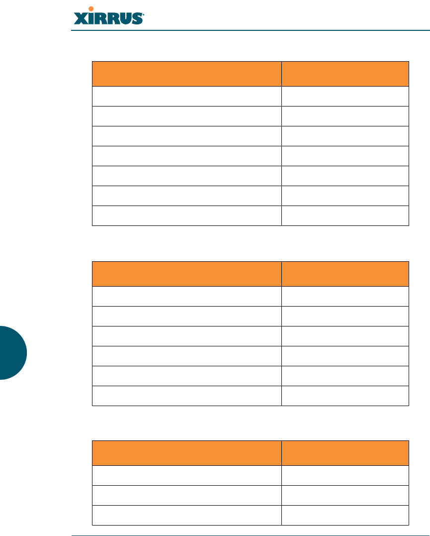
Gigabit 1 and Gigabit 2
Setting Default Value
Host name Xirrus-WiFi-Array
Setting Default Value
Baud Rate 115200
Word Size 8 bits
Stop Bits 1
Parity No parity
Time Out 10 seconds
Setting Default Value
Enabled Yes
Wi-Fi Array
324 Appendix B: Quick Reference Guide
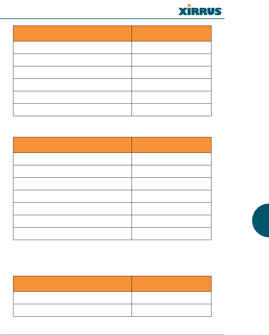
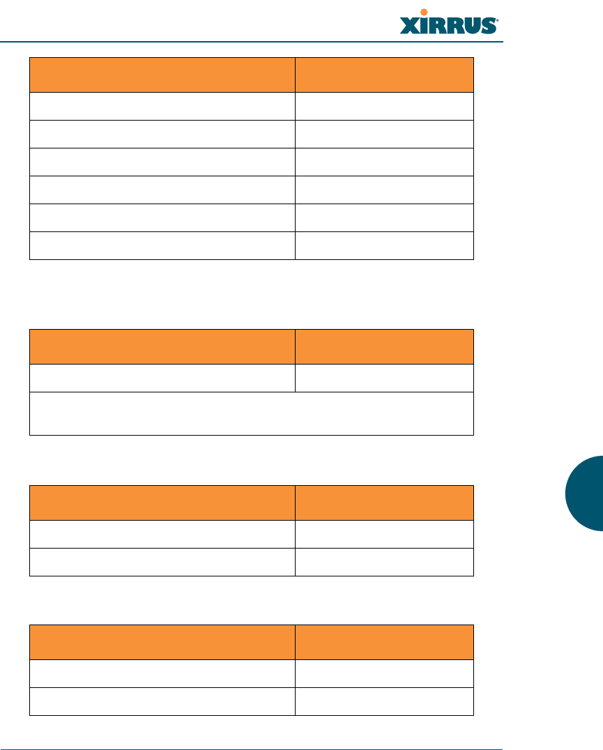
Fast Ethernet
DHCP Bind Yes
Default IP Address 10.0.2.1
Default IP Mask 255.255.255.0
Default Gateway None
Auto Negotiate On
Duplex Full
Speed 1000 Mbps
MTU Size 1504
Management Enabled Yes
Setting Default Value
Enabled Yes
DHCP Bind Yes
Default IP Address 10.0.1.1
Default IP Mask 255.255.255.0
Default Gateway None
Auto Negotiate On
Duplex Full
Speed 100 Mbps
MTU Size 1500
Management Enabled Yes
Setting Default Value

Wi-Fi Array
Appendix B: Quick Reference Guide 325
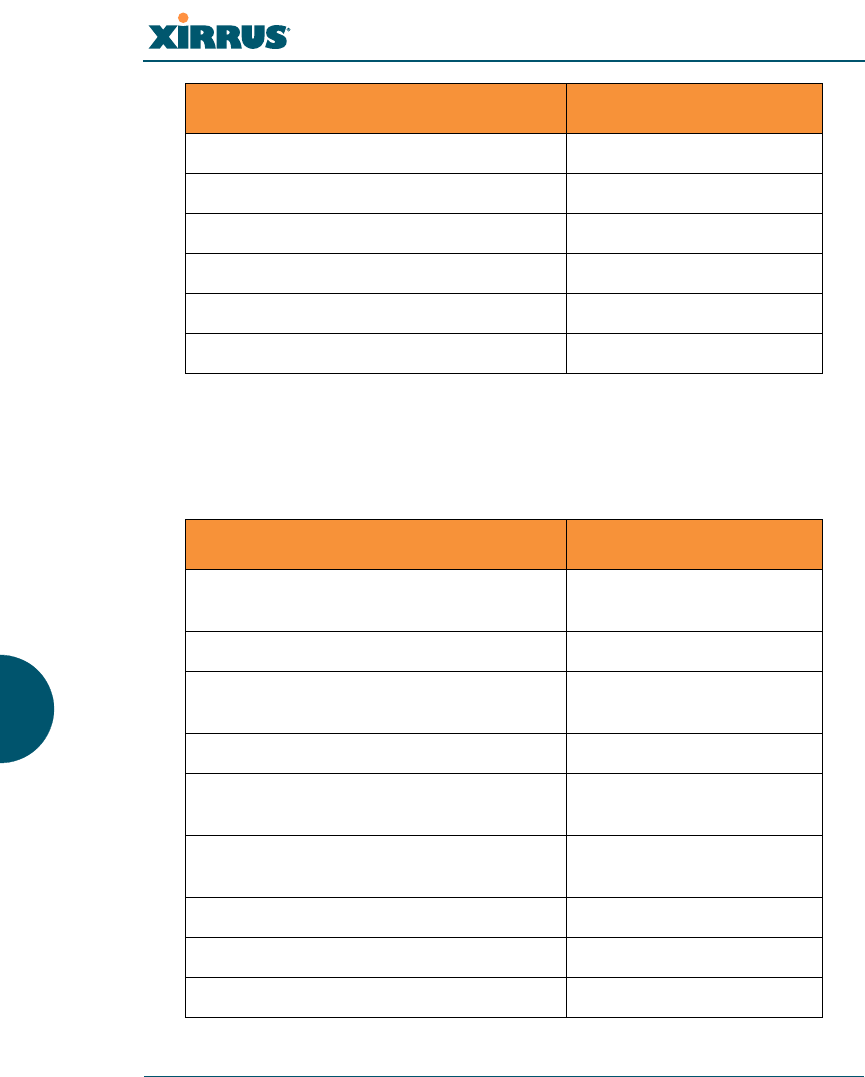
Integrated Access Points (IAPs)
Server Settings
NTP
Setting Default Value
IAP abg2 Defaults Enabled
Mode = Monitor
Channel = Monitor
Cell Size = Manual
Antenna = Internal-Omni
Enabled (Radio State) No
Mode
zXN16
zXN8
zXN4
802.11an for a1 to a12
802.11bg for abg1 to abg4
802.11an for a1 to a4
802.11bg for abg1 to abg4
802.11bg for abg1 to abg4
Channel Auto
Cell Size Max
Maximum Transmit Power 20
Antenna Selected Internal
Setting Default Value
Enabled No
Primary time.nist.gov
Secondary pool.ntp.org
Wi-Fi Array
326 Appendix B: Quick Reference Guide
Syslog
SNMP
DHCP
Setting Default Value
Enabled Yes
Local Syslog Level Information
Maximum Internal Records 500
Primary Server None
Primary Syslog Level Information
Secondary Server None
Secondary Syslog Level Information
Setting Default Value
Enabled Yes
Read-Only Community String xirrus_read_only
Read-Write Community String xirrus
Trap Host null (no setting)
Trap Port 162
Authorization Fail Port On
Setting Default Value
Enabled No
Maximum Lease Time 300 minutes
Default Lease Time 300 minutes
Wi-Fi Array
Appendix B: Quick Reference Guide 327
Default SSID
Security
Global Settings - Encryption
IP Start Range 192.168.1.2
IP End Range 192.168.1.254
NAT Disabled
IP Gateway None
DNS Domain None
DNS Server (1 to 3) None
Setting Default Value
ID xirrus
VLAN None
Encryption Off
Encryption Type None
QoS 2
Enabled Yes
Broadcast On
Setting Default Value
Enabled Yes
WEP Keys null (all 4 keys)
Setting Default Value
Wi-Fi Array
328 Appendix B: Quick Reference Guide
External RADIUS (Global)
WEP Key Length null (all 4 keys)
Default Key ID 1
WPA Enabled No
TKIP Enabled Yes
AES Enabled Yes
EAP Enabled Yes
PSK Enabled No
Pass Phrase null
Group Rekey Disabled
Setting Default Value
Enabled Yes
Primary Server None
Primary Port 1812
Primary Secret xirrus
Secondary Server null (no IP address)
Secondary Port 1812
Secondary Secret null (no secret)
Time Out (before primary server is
retired) 600 seconds
Accounting Disabled
Interval 300 seconds
Setting Default Value
Wi-Fi Array
Appendix B: Quick Reference Guide 329
Internal RADIUS
Administrator Account and Password
Management
Primary Server None
Primary Port 1813
Primary Secret xirrus
Secondary Server None
Secondary Port 1813
Secondary Secret null (no secret)
Setting Default Value
Enabled No
The user database is cleared upon reset to the factory defaults. For the
Internal RADIUS Server you have a maximum of 1,000 entries.
Setting Default Value
ID admin
Password admin
Setting Default Value
SSH On
SSH timeout 300 seconds
Setting Default Value
Wi-Fi Array
330 Appendix B: Quick Reference Guide
Keyboard Shortcuts
The following table shows the most common keyboard shortcuts used by the
Command Line Interface.
Telnet Off
Telnet timeout 300 seconds
Serial On
Serial timeout 300 seconds
Management over IAPs Off
http timeout 300 seconds
Action Shortcut
Cut selected data and place it on the
clipboard. Ctrl + X
Copy selected data to the clipboard. Ctrl + C
Paste data from the clipboard into a
document (at the insertion point). Ctrl + V
Go to top of screen. Ctrl + Z
Copy the active window to the
clipboard. Alt + Print Screen
Copy the entire desktop image to the
clipboard. Print Screen
Abort an action at any time. Esc
Go back to the previous screen. b
Access the Help screen. ?
Setting Default Value

Wi-Fi Array
Appendix B: Quick Reference Guide 331
See Also
An Overview

Wi-Fi Array
332 Appendix B: Quick Reference Guide
Use this Space for Your Notes

Wi-Fi Array
Appendix C: Technical Support 333
Appendix C: Technical Support
This appendix provides valuable support information that can help you resolve
technical difficulties. Before contacting Xirrus, review all topics below and try to
determine if your problem resides with the Wi-Fi Array or your network
infrastructure. Topics include:
z“General Hints and Tips” on page 333
z“Frequently Asked Questions” on page 334
z“Array Monitor and Loopback Testing Capabilities” on page 341
z“Upgrading the Array via CLI” on page 344
z“Contact Information” on page 349
z“Contact Information” on page 349
General Hints and Tips
This section provides some useful tips that will optimize the reliability and
performance of your Wi-Fi Arrays.
zThe Wi-Fi Array requires careful handling. For best performance, units
should be mounted in a dust-free and temperature-controlled
environment.
zIf using multiple Arrays in the same area, maintain a distance of at least
100 feet (30m) between Arrays if there is direct line-of-sight between the
units, or at least 50 feet (15 m) if a wall or other barrier exists between the
units.
zKeep the Wi-Fi Array away from electrical devices or appliances that
generate RF noise. Because the Array is generally mounted on ceilings, be
aware of its position relative to lighting (especially fluorescent lighting).
zIf using AC power, each Wi-Fi Array requires its own dedicated AC
power outlet. Do not attempt to “piggy-back” AC power to multiple
units. To avoid needing to run separate power cables to one or more
Arrays, consider using Power over Gigabit Ethernet.

Wi-Fi Array
334 Appendix C: Technical Support
zIf you are deploying multiple units, the Array should be oriented so that
the abg2 radio is oriented in the direction of the least required coverage,
because when in monitor mode the abg2 radio does not function as an AP
servicing stations.
zThe Wi-Fi Array should only be used with Wi-Fi certified client devices.
See Also
Contact Information
Multiple SSIDs
Security
VLAN Support
Frequently Asked Questions
This section answers some of the most frequently asked questions, organized by
functional area.
Multiple SSIDs
Q. What Are BSSIDs and SSIDs?
A. BSSID (Basic Service Set Identifier) refers to an individual access point
radio and its associated clients. The identifier is the MAC address of the
access point radio that forms the BSS.
A group of BSSs can be formed to allow stations in one BSS to
communicate to stations in another BSS by way of a backbone that
interconnects each access point.
The Extended Service Set (ESS) refers to the group of BSSIDs that are
grouped together to form one ESS. The ESSID (often referred to as SSID or
“wireless network name”) identifies the Extended Service Set. Clients
must associate to a single ESS at any given time. Clients ignore traffic
from other Extended Service Sets that do not have the same SSID.
Legacy access points typically support one SSID per access point. Xirrus
Wi-Fi Arrays support the ability for multiple SSIDs to be defined and
used simultaneously.

Wi-Fi Array
Appendix C: Technical Support 335
Q. What would I use SSIDs for?
A. The creation of different wireless network names allows system
administrators to separate types of users with different requirements. The
following policies can be tied to an SSID:
zMinimum security required to join this SSID.
zThe wireless Quality of Service (QoS) desired for this SSID.
zThe wired VLAN associated with this SSID.
As an example, one SSID named accounting might require the highest
level of security, while another SSID named guests might have low
security requirements.
Another example may define an SSID named voice that supports voice
over Wireless LAN phones with the highest possible Quality of Service
(QoS) definition. This type of SSID might also forward traffic to specific
VLANs on the wired network.
Q. How do I set up SSIDs?
A. Use the following procedure as a guideline. For more detailed
information, go to “SSIDs” on page 184.
1. From the Web Management Interface, go to the SSID
Management page.
2. Select Yes to make the SSID visible to all clients on the network.
Although the Wi-Fi Array will not broadcast SSIDs that are
hidden, clients can still associate to a hidden SSID if they know
the SSID name to connect to it.
3. Select the minimum security that will be required by users for
this SSID.
4. If desired (optional), select a Quality of Service (QoS) setting for
this SSID. The QoS setting you define here will prioritize wireless
traffic for this SSID over other SSID wireless traffic.
5. If desired (optional), select a VLAN that you want this traffic to
be forwarded to on the wired network.

Wi-Fi Array
336 Appendix C: Technical Support
6. If desired (optional), you can select which radios this SSID will
not be available on—the default is to make this SSID available on
all radios.
7. Click on the Apply button to apply your changes to this session.
8. Click on the Save button to save your changes.
9. If you need to edit any of the SSID settings, you can do so from
the SSID Management page.
See Also
Contact Information
General Hints and Tips
Security
SSIDs
SSID Management
VLAN Support
Security
Q. How do I know my management session is secure?
A. Follow these guidelines:
zAdministrator passwords
Always change the default administrator password (the default
is admin), and choose a strong replacement password. When
appropriate, issue read only administrator accounts.
zSSH versus Telnet
Be aware that Telnet is not secure over network connections and
should be used only with a direct serial port connection. When
connecting to the unit’s Command Line Interface over a network
connection, you must use a Secure SHell (SSH) utility. The most
commonly used freeware providing SSH tools is PuTTY.
zConfiguration auditing

Wi-Fi Array
Appendix C: Technical Support 337
Do not change approved configuration settings. The optional
Xirrus Management System (XMS) offers powerful management
features for small or large Wi-Fi Array deployments, and can
audit your configuration settings automatically. In addition,
using the XMS eliminates the need for an FTP server.
Q. Which wireless data encryption method should I use?
A. Wireless data encryption prevents eavesdropping on data being
transmitted or received over the airwaves. The Wi-Fi Array allows you to
establish the following data encryption configuration options:
zOpen
This option offers no data encryption and is not recommended,
though you might choose this option if clients are required to use
a VPN connection through a secure SSH utility, like PuTTy.
zWEP (Wired Equivalent Privacy)
This option provides minimal protection (though much better
than using an open network). An early standard for wireless data
encryption and supported by all Wi-Fi certified equipment, WEP
is vulnerable to hacking and is therefore not recommended for
use by Enterprise networks.
zWPA (Wi-Fi Protected Access)
This is a much stronger encryption model than WEP and uses
TKIP (Temporal Key Integrity Protocol) with AES (Advanced
Encryption Standard) to prevent WEP cracks.
TKIP solves security issues with WEP. It also allows you to
establish encryption keys on a per-user-basis, with key rotation
for added security. In addition, TKIP provides Message Integrity
Check (MIC) functionality and prevents active attacks on the
wireless network.
AES is the strongest encryption standard and is used by
government agencies; however, old legacy hardware may not be
capable of supporting the AES mode (it probably won’t work on
older wireless clients). Because AES is the strongest encryption

Wi-Fi Array
338 Appendix C: Technical Support
standard currently available, it is highly recommended for
Enterprise networks.
Any of the above encryption modes can be used (and can be used at
the same time).
Q. Which user authentication method should I use?
A. User authentication ensures that users are who they say they are. For
example, the most obvious example of authentication is logging in with a
user name and password. The Wi-Fi Array allows you to choose between
the following user authentication methods:
zPre-Shared Key
Users must manually enter a key (pass phrase) on the client side
of the wireless network that matches the key stored by the
administrator in your Wi-Fi Arrays.
zRADIUS 802.1x with EAP
802.1x uses a RADIUS server to authenticate large numbers of
clients, and can handle different EAP (Extensible Authentication
Protocol) authentication methods, including EAP-TLS, EAP-
TTLS and EAP-PEAP. The RADIUS server can be internal
(provided by the Wi-Fi Array) or external. An external RADIUS
server offers more functionality and is recommended for large
Enterprise deployments.
When using this method, user names and passwords must be
entered into the RADIUS server for user authentication.
zMAC Address ACLs (Access Control Lists)
MAC address ACLs provide a list of client adapter MAC
addresses that are allowed or denied access to the wireless
network. Access Control Lists work well when there are a limited
number of users—in this case, enter the MAC addresses of each
user in the Allow list. In the event of a lost or stolen MAC
adapter, enter the affected MAC address in the Deny list.
Q. Why do I need to authenticate my Wi-Fi Array units?

Wi-Fi Array
Appendix C: Technical Support 339
A. When deploying multiple Wi-Fi Arrays, you may need to define which
units are part of which wireless network (for example, if you are
establishing more than one network). In this case, you need to employ the
Xirrus Management System (XMS) which can authenticate your Arrays
automatically and ensure that only authorized units are associated with
the defined wireless network.
Q. What is rogue AP (Access Point) detection?
A. The Wi-Fi Array has a dedicated radio (abg/4) which constantly scans the
local wireless environment for rogue APs (non-Xirrus devices that are not
part of your wireless network), unencrypted transmissions, and other
security issues. Administrators can then classify each rogue AP and
ensure that these devices do not interrupt or interfere with the network.
See Also
Contact Information
General Hints and Tips
Multiple SSIDs
VLAN Support
VLAN Support
Q. What Are VLANs?
A. VLANs (Virtual Local Area Networks) are a logical grouping of network
devices that share a common network broadcast domain. Members of a
particular VLAN can be on any segment of the physical network but
logically only members of a particular VLAN can see each other.
VLANs are defined and implemented using the wired network switches
that are VLAN capable. Packets are tagged for transmission on a
particular VLAN according to the IEEE 802.1Q standard, with VLAN
switches processing packets according to the tag.
Q. What would I use VLANs for?

Wi-Fi Array
340 Appendix C: Technical Support
A. Logically separating different types of users, systems, applications, or
other logical division aids in performance and management of different
network devices. Different VLANs can also be assigned with different
packet priorities to prioritize packets from one VLAN over packets from
another VLAN.
VLANs are managed by software settings—instead of physically
plugging in and moving network cables and users—which helps to ease
network management tasks.
Q. What are Wireless VLANs?
A. Wireless VLANs allow similar functionality to the wired VLAN
definitions and extend the operation of wired VLANs to the wireless side
of the network.
Wireless VLANs can be mapped to wireless SSIDs so that traffic from
wired VLANs can be sent to wireless users of a particular SSID. The
reverse is also true, where wireless traffic originating from a particular
SSID can be tagged for transmission on a particular wired VLAN.
Sixteen SSIDs can be defined on your Wi-Fi Array, allowing a total of
sixteen VLANs to be accessed (one per SSID).
As an example, to provide guest user access an SSID of guest might be
created. This SSID could be mapped to a wired VLAN that segregates
unknown users from the rest of the wired network and restricts them to
Internet access only. Wireless users could then associate to the wireless
network via the guest SSID and obtain access to the Internet through the
selected VLAN, but would be able to access other privileged network
resources.
See Also
Contact Information
General Hints and Tips
Multiple SSIDs
Security

Wi-Fi Array
Appendix C: Technical Support 341
Array Monitor and Loopback Testing Capabilities
All models of the Wi-Fi Array have a monitor radio, abg2, that checks that the
Array’s radios are functioning correctly, and acts as a dedicated threat sensor to
detect and prevent intrusion from rogue access points.
Enabling Monitoring on the Array
IAP abg2 may be set to monitor the Array or to be a normal IAP radio. In order to
enable the functions required for intrusion detection and for monitoring the other
Array radios, you must configure abg2 on the IAP Settings window as follows:
zCheck the Enabled checkbox.
zSet Mode to Monitor.
zSet Channel to Monitor.
The settings above will automatically set the Antenna selection to
Internal-Omni., also required for monitoring. See the “IAP Settings” on page 204
for more details. The values above are the factory default settings for the Array.
How Monitoring Works
When the monitor radio abg2 has been configured as just described, it performs
these steps continuously (24/7) to check the other radios on the Array and detect
possible intrusions:
1. The monitor radio scans all channels with a 200ms dwell time, hitting all
channels about once every 10 seconds.
2. Each time it tunes to a new channel it sends out a probe request in an
attempt to smoke out rogues.
3. It then listens for all probe responses and beacons to detect any rogues
within earshot.
4. Array radios respond to that probe request with a probe response.
Intrusion Detection is enabled or disabled separately from monitoring. See Step 1
in “Advanced RF Settings” on page 221. Note that the Advanced setting is only
used with the optional Xirrus Defense Module (XDM) software package.

Wi-Fi Array
342 Appendix C: Technical Support
Loopback Testing
The Array is capable of performing continuous, comprehensive tests on its radios
to assure that they are operating properly. Testing is enabled using the Radio
Assurance Mode setting on the Advanced RF Settings window (Step 5 in
“Advanced RF Settings” on page 221). When this mode is enabled, IAP abg2
performs loopback tests on the Array. Radio Assurance Mode (also called
loopback mode) requires Intrusion Detection to be set to Standard (See Step 1 in
“Advanced RF Settings” on page 221).
When Loopback Mode is enabled:
1. The Array keeps track of whether or not it hears beacons and probe
responses from the Array’s radios.
2. After 10 minutes (roughly 60 passes on a particular channel by the
monitor radio), if it has not heard beacons or probe responses from one of
the Array’s radios it issues an alert in the Syslog. If repair is allowed (see
“Loopback Mode Options” on page 343), the Array will reset and
reprogram that particular radio at the Physical Layer (PHY—Layer 1).
This action takes under 100ms and stations are not deauthenticated, thus
users should not be impacted.
3. After another 10 minutes (roughly another 60 passes), if the monitor still
has not heard beacons or probe responses from the malfunctioning radio
it will again issue an alert in the Syslog. If repair is allowed, the Array will
reset and reprogram the MAC (the lower sublayer of the Data Link Layer)
and then all of the PHYs. This is a global action that affects all radios. This
action takes roughly 300ms and stations are not deauthenticated, thus
users should not be impacted.
4. After another 10 minutes, if the monitor still has not heard beacons or
probe responses from that radio, it will again syslog the issue. If reboot is
allowed (see “Loopback Mode Options” on page 343), the Array will
schedule a reboot. This reboot will occur at one of the following times,
whichever occurs first:
•When no stations are associated to the Array
•Midnight

Wi-Fi Array
Appendix C: Technical Support 343
Loopback Mode Options
If the monitor detects a problem with an Array radio as described above, it will
take action according to the preference that you have specified in the Radio
Assurance Mode setting on the Advanced RF Settings window (see Step 5
page 223):
zFailure alerts only—The Array will issue alerts in the Syslog, but will not
initiate repairs or reboots.
zFailure alerts & repairs, but no reboots—The Array will issue alerts and
perform resets of the PHY and MAC as described above.
zFailure alerts & repairs & reboots if needed—The Array will issue alerts,
perform resets of the PHY and MAC, and schedule reboots as described
above.
zDisabled—Disable IAP loopback tests (no self-monitoring occurs).
Loopback tests are disabled by default.

Wi-Fi Array
344 Appendix C: Technical Support
Upgrading the Array via CLI
If you are experiencing difficulties communicating with the Array using the Web
Management Interface, the Array provides lower-level facilities that may be used
to accomplish an upgrade via the CLI and the Xirrus Boot Loader (XBL).
1. Download the latest software update from the Xirrus FTP site using your
Enhanced Care FTP username and password. If you do not have an FTP
username and password, contact Xirrus Customer Service for assistance
(support@xirrus.com). The software update is provided as a zip file.
Unzip the contents to a local temp directory. Take note of the extracted file
name in case you need it later on—you may also need to copy this file
elsewhere on the network depending on your situation.
2. Install a TFTP server software package if you don't have one running. It
may be installed on any PC on your network, including your desktop or
laptop. The Solar Winds version is freeware and works well.
http://support.solarwinds.net/updates/New-customerFree.cfm?ProdId=52
The TFTP install process creates the TFTP-Root directory on your C:
drive, which is the default target for sending and receiving files. This may
be changed if desired. This directory is where you will place the extracted
Xirrus software update file(s). If you install the TFTP server on the same
computer to which you extracted the file, you may change the TFTP
directory to C:\xirrus if desired.
You must make the following change to the default configuration of the
Solar Winds TFTP server. In the File/Configure menu, select Security,
then select Tra nsmi t o nly and click OK.
3. Determine the IP address of the computer hosting the TFTP server. (To
display the IP address, open a command prompt and type ipconfig)
4. Connect your Array to the computer running TFTP using a serial cable,
and open a terminal program if you haven't already. Attach a network
cable to the Array’s GIG1 port, if it is not already part of your network.

Wi-Fi Array
Appendix C: Technical Support 345
Boot your Array and watch the progress messages. When Press space bar
to exit to bootloader: is displayed, press the space bar. The rest of this
procedure is performed using the bootloader.
The following steps assume that you are running DHCP on your local
network.
5. Type dhcp and hit return. This instructs the Array to obtain a DHCP
address and use it during this boot in the bootloader environment.
6. Type dir and hit return to see what's currently in the compact flash.
7. Type del and hit return to delete the contents of the compact flash.
8. Type update server <TFTP-server-ip-addr> xs-3.x-xxxx.bin (the actual
Xirrus file name will vary depending on Array model number and
software version—use the file name from your software update) and hit
return. The software update will be transferred to the Array's memory
and will be written to the it’s compact flash card. (See output below.)
9. Type reset and hit return. Your Array will reboot, running your new
version of software.
Sample Output for the Upgrade Procedure:
The user actions are highlighted in the output below, for clarity.
Username: admin
Password: *****
Xirrus-WiFi-Array# configure
Xirrus-WiFi-Array(config)# reboot
Are you sure you want to reboot? [yes/no]: yes
Array is being rebooted.
Xirrus Boot Loader 1.0.0 (Oct 17 2006 - 13:11:42), Build: 2725
Processor | Motorola PowerPC, PVR=80200020 SVR=80300020
Board | Xirrus MPC8540 CPU Board
Clocks | CPU : 825 MHz DDR : 330 MHz Local Bus: 41 MHz

Wi-Fi Array
346 Appendix C: Technical Support
L1 cache | Data: 32 KB Inst: 32 KB Status : Enabled
Watchdog | Enabled (5 secs)
I2C Bus | 400 KHz
DTT | CPU:34C RF0:34C RF1:34C RF2:27C RF3:29C
RTC | Wed 2007-Nov-05 6:43:14 GMT
System DDR | 256 MB, Unbuffered Non-ECC (2T)
L2 cache | 256 KB, Enabled
FLASH | 4 MB, CRC: OK
FPGA | 2 Devices programmed
Packet DDR | 256 MB, Unbuffered Non-ECC, Enabled
Network | Mot FEC Mot TSEC1 [Primary] Mot TSEC2
IDE Bus 0 | OK
CFCard | 122 MB, Model: Hitachi XXM2.3.0
Environment| 4 KB, Initialized
In: serial
Out: serial
Err: serial
Press space bar to exit to bootloader:
XBL>dhcp
[DHCP ] Device : Mot TSEC1 1000BT Full Duplex
[DHCP ] IP Addr : 192.168.39.195
XBL>dir
[CFCard] Directory of /
Date Time Size File or Directory name
----------- -------- -------- ---------------------------
2007-Nov-05 6:01:56 29 lastboot
2007-Apr-05 15:47:46 28210390 xs-3.1-0433.bak
2007-Mar-01 16:39:42 storage/
2007-Apr-05 15:56:38 28210430 xs-3.1-0440.bin
2007-Mar-03 0:56:28 wpr/
3 file(s), 2 dir(s)

Wi-Fi Array
Appendix C: Technical Support 347
XBL>del *
[CFCard] Delete : 2 file(s) deleted
XBL>update server 192.168.39.102 xs-3.0-0425.bin
[TFTP ] Device : Mot TSEC1 1000BT Full Duplex
[TFTP ] Client : 192.168.39.195
[TFTP ] Server : 192.168.39.102
[TFTP ] File : xs-3.0-0425.bin
[TFTP ] Address : 0x1000000
[TFTP ] Loading : ##################################################
[TFTP ] Loading : ##################################################
[TFTP ] Loading : ###### done
[TFTP ] Complete: 12.9 sec, 2.1 MB/sec
[TFTP ] Bytes : 27752465 (1a77811 hex)
[CFCard] File : xs-3.0-0425.bin
[CFCard] Address : 0x1000000
[CFCard] Saving : ############################################### done
[CFCard] Complete: 137.4 sec, 197.2 KB/sec
[CFCard] Bytes : 27752465 (1a77811 hex)
XBL>reset
[RESET ]
Xirrus Boot Loader 1.0.0 (Oct 17 2006 - 13:11:42), Build: 2725
Processor | Motorola PowerPC, PVR=80200020 SVR=80300020
Board | Xirrus MPC8540 CPU Board
Clocks | CPU : 825 MHz DDR : 330 MHz Local Bus: 41 MHz
L1 cache | Data: 32 KB Inst: 32 KB Status : Enabled
Watchdog | Enabled (5 secs)
I2C Bus | 400 KHz
DTT | CPU:33C RF0:32C RF1:31C RF2:26C RF3:27C
RTC | Wed 2007-Nov-05 6:48:44 GMT
System DDR | 256 MB, Unbuffered Non-ECC (2T)

Wi-Fi Array
348 Appendix C: Technical Support
L2 cache | 256 KB, Enabled
FLASH | 4 MB, CRC: OK
FPGA | 2 Devices programmed
Packet DDR | 256 MB, Unbuffered Non-ECC, Enabled
Network | Mot FEC Mot TSEC1 [Primary] Mot TSEC2
IDE Bus 0 | OK
CFCard | 122 MB, Model: Hitachi XXM2.3.0
Environment| 4 KB, Initialized
In: serial
Out: serial
Err: serial
Press space bar to exit to bootloader:
[CFCard] File : xs*.bin
[CFCard] Address : 0x1000000
[CFCard] Loading : ############################################### done
[CFCard] Complete: 26.9 sec, 1.0 MB/sec
[CFCard] Bytes : 27752465 (1a77811 hex)
[Boot ] Address : 0x01000000
[Boot ] Image : Verifying checksum .... OK
[Boot ] Unzip : Multi-File Image .... OK
[Boot ] Initrd : Loading RAMDisk Image
[Boot ] Initrd : Verifying checksum .... OK
[Boot ] Execute : Transferring control to OS
Initializing hardware ........................................ OK
Xirrus Wi-Fi Array
ArrayOS Version 3.0-425
Copyright (c) 2005-2007 Xirrus, Inc.
http://www.xirrus.com
Username:

Wi-Fi Array
Appendix C: Technical Support 349
Contact Information
Xirrus, Inc. is located in Westlake Village, California, just 45 minutes northwest of
downtown Los Angeles and 45 minutes southeast of Santa Barbara.
Xirrus, Inc.
370 North Westlake Blvd, Suite 200
Westlake Village, CA 91362
USA
Tel: 1.805.497.0955
Fax: 1.805.449.1180
www.xirrus.com
support.xirrus.com

Wi-Fi Array
350 Appendix C: Technical Support

Wi-Fi Array
Glossary of Terms 351
Glossary of Terms
802.11a
A supplement to the IEEE 802.11 WLAN specification that describes radio
transmissions at a frequency of 5 GHz and data rates of up to 54 Mbps.
802.11b
A supplement to the IEEE 802.11 WLAN specification that describes radio
transmissions at a frequency of 2.4 GHz and data rates of up to 11 Mbps.
802.11d
A supplement to the Media Access Control (MAC) layer in 802.11 to promote
worldwide use of 802.11 WLANs. It allows Access Points to communicate
information on the permissible radio channels with acceptable power levels for
user devices. Because the 802.11 standards cannot legally operate in some
countries, 802.11d adds features and restrictions to allow WLANs to operate
within the rules of these countries.
802.11g
A supplement to the IEEE 802.11 WLAN specification that describes radio
transmissions at a frequency of 2.4 GHz and data rates of up to 54 Mbps.
802.1Q
An IEEE standard for MAC layer frame tagging (also known as encapsulation).
Frame tagging uniquely assigns a user-defined ID to each frame. It also enables a
switch to communicate VLAN membership information across multiple (and
multi-vendor) devices by frame tagging.
AES
(Advanced Encryption Standard) A data encryption scheme that uses three
different key sizes (128-bit, 192-bit, and 256-bit). AES was adopted by the U.S.
government in 2002 as the encryption standard for protecting sensitive but
unclassified electronic data.

Wi-Fi Array
352 Glossary of Terms
authentication
The process that a station, device, or user employs to announce its identify to
the network which validates it. IEEE 802.11 specifies two forms of authentication,
open system and shared key.
bandwidth
Specifies the amount of the frequency spectrum that is usable for data transfer. In
other words, it identifies the maximum data rate a signal can attain on
the medium without encountering significant attenuation (loss of power).
beacon interval
When a device in a wireless network sends a beacon, it includes with it a beacon
interval, which specifies the period of time before it will send the beacon again.
The interval tells receiving devices on the network how long they can wait in low
power mode before waking up to handle the beacon. Network administrators can
adjust the beacon interval—usually measured in milliseconds (ms) or its
equivalent, kilo-microseconds (Kmsec).
bit rate
The transmission rate of binary symbols ('0' and '1'), equal to the total number of
bits transmitted in one second.
BSS
(Basic Service Set) When a WLAN is operating in infrastructure mode, each access
point and its connected devices are called the Basic Service Set.
BSSID
The unique identifier for an access point in a BSS network. See also, SSID.
CDP
(Cisco Discovery Protocol) CDP is a layer 2 network protocol which runs on most
Cisco equipment and some other network equipment. It is used to share
information with other directly connected network devices. Information such as
the model, network capabilities, and IP address is shared. Wi-Fi Arrays can both
advertise their presence by sending CDP announcements, and gather and display
information sent by neighbors.

Wi-Fi Array
Glossary of Terms 353
cell
The basic geographical unit of a cellular communications system. Service
coverage of a given area is based on an interlocking network of cells, each with a
radio base station (transmitter/receiver) at its center. The size of each cell is
determined by the terrain and forecasted number of users.
channel
A specific portion of the radio spectrum—the channels allotted to one of
the wireless networking protocols. For example, 802.11b and 802.11g use 14
channels in the 2.4 GHz band, only 3 of which don't overlap (1, 6, and 11). In the 5
GHz band, 802.11a uses 8 channels for indoor use and 4 for outdoor use, none of
which overlap. In the U.S., additional channels are available, to bring the total to
24 channels.
CoS
(Class of Service) A category based on the type of user, type of application,
or some other criteria that QoS systems can use to provide differentiated classes of
service.
default gateway
The gateway in a network that a computer will use to access another network if
a gateway is not specified for use. In a network using subnets, a default gateway
is the router that forwards traffic to a destination outside of the subnet of
the transmitting device.
DHCP
(Dynamic Host Configuration Protocol) A method for dynamically assigning IP
addresses to devices on a network. DHCP issues IP addresses automatically
within a specified range to client devices when they are first powered up.
DHCP lease
The DHCP lease is the amount of time that the DHCP server grants to the DHCP
client for permission to use a particular IP address. A typical DHCP server allows
its administrator to set the lease time.

Wi-Fi Array
354 Glossary of Terms
DNS
(Domain Name System) A system that maps meaningful domain names with
complex numeric IP addresses. DNS is actually a separate network—if one DNS
server cannot translate a domain name, it will ask a second or third until a server
is found with the correct IP address.
domain
The main name/Internet address of a user's Internet site as registered with
the InterNIC organization, which handles domain registration on the Internet. For
example, the “domain” address for Xirrus is: http://www.xirrus.com, broken
down as follows:
zhttp:// represents the Hyper Text Teleprocessing Protocol used by all Web
pages.
zwww is a reference to the World Wide Web.
zxirrus refers to the company.
zcom specifies that the domain belongs to a commercial enterprise.
DTIM
(Delivery Traffic Indication Message) A DTIM is a signal sent as part of a beacon
by an access point to a client device in sleep mode, alerting the device to a packet
awaiting delivery.
EAP
(Extensible Authentication Protocol) When you log on to the Internet, you're most
likely establishing a PPP connection via a remote access server. The password,
key, or other device you use to prove that you are authorized to do so is controlled
via PPP’s Link Control Protocol (LCP). However, LCP is somewhat inflexible
because it has to specify an authentication device early in the process. EAP allows
the system to gather more information from the user before deciding which
authenticator to use. It is called extensible because it allows more authenticator
types than LCP (for example, passwords and public keys).

Wi-Fi Array
Glossary of Terms 355
EDCF
(Enhanced Distributed Coordinator Function) A QoS extension which uses
the same contention-based access mechanism as current devices but adds “offset
contention windows” that separate high priority packets from low priority
packets (by assigning a larger random backoff window to lower priorities than to
higher priorities). The result is “statistical priority,” where high-priority packets
usually are transmitted before low-priority packets.
encapsulation
A way of wrapping protocols such as TCP/IP, AppleTalk, and NetBEUI in
Ethernet frames so they can traverse an Ethernet network and be unwrapped
when they reach the destination computer.
encryption
Any procedure used in cryptography to translate data into a form that can be
decrypted and read only by its intended receiver.
Fast Ethernet
A version of standard Ethernet that runs at 100 Mbps rather than 10 Mbps.
FCC
(Federal Communications Commission) US wireless regulatory authority.
The FCC was established by the Communications Act of 1934 and is charged with
regulating Interstate and International communications by radio, television, wire,
satellite and cable.
frame
A packet encapsulated to travel on a physical medium, like Ethernet or Wi-Fi. If a
packet is like a shipping container, a frame is the boat on which the shipping
container is loaded.
Gigabit 1
The primary Gigabit Ethernet interface. See also, Gigabit Ethernet.
Gigabit 2
The secondary Gigabit Ethernet interface. See also, Gigabit Ethernet.
Gigabit Ethernet
The newest version of Ethernet, with data transfer rates of 1 Gigabit (1,000 Mbps).

Wi-Fi Array
356 Glossary of Terms
Group
A user group, created to define a set of attributes (such as VLAN, traffic limits,
and Web Page Redirect) and privileges (such as fast roaming) that apply to all
users that are members of the group. This allows a uniform configuration to be
easily applied to multiple user accounts. The attributes that can be configured for
user groups are almost identical to those that can be configured for SSIDs.
host name
The unique name that identifies a computer on a network. On the Internet,
the host name is in the form comp.xyz.net. If there is only one Internet site
the host name is the same as the domain name. One computer can have more than
one host name if it hosts more than one Internet site (for example, home.xyz.net
and comp.xyz.net). In this case, comp and home are the host names and xyz.net is
the domain name.
IPsec
A Layer 3 authentication and encryption protocol. Used to secure VPNs.
MAC address
(Media Access Control Address) A 6-byte hexadecimal address assigned by a
manufacturer to a device.
Mbps
(Megabits per second) A standard measure for data transmission speeds (for
example, the rate at which information travels over the Internet). 1 Mbps denotes
one million bits per second.
MTU
(Maximum Transmission Unit) The largest physical packet size—measured in
bytes—that a network can transmit. Any messages larger than the MTU are
divided into smaller packets before being sent. Every network has a different
MTU, which is set by the network administrator. Ideally, you want the MTU to be
the same as the smallest MTU of all the networks between your machine and
a message's final destination. Otherwise, if your messages are larger than one of
the intervening MTUs, they will get broken up (fragmented), which slows down
transmission speeds.

Wi-Fi Array
Glossary of Terms 357
NTP
(Network Time Protocol) An Internet standard protocol (built on top of TCP/IP)
that ensures the accurate synchronization (to the millisecond) of computer clock
times in a network of computers. Running as a continuous background client
program on a computer, NTP sends periodic time requests to servers, obtaining
server time stamps and using them to adjust the client's clock.
packet
Data sent over a network is broken down into many small pieces—packets—by
the Transmission Control Protocol layer of TCP/IP. Each packet contains the
address of its destination as well the data. Packets may be sent on any number of
routes to their destination, where they are reassembled into the original data. This
system is optimal for connectionless networks, such as the Internet, where there
are no fixed connections between two locations.
PLCP
(Physical Layer Convergence Protocol) Defined by IEEE 802.6, a protocol
specified within the Transmission Convergence layer that defines exactly how
cells are formatted within a data stream for a particular type of transmission
facility.
PoGE
This refers to the optional Xirrus XP1 Power over Gigabit Ethernet modules that
provide DC power to Arrays. Power is supplied over the same Cat 5e or Cat 6
cable that supplies the data connection to your gigabit Ethernet switch, thus
eliminating the need to run a power cable. See “Contact Information” on page 349
for a list of Xirrus PoGE modules and the modules that are compatible with each
Array.
preamble
Preamble (sometimes called a header) is a section of data at the head of a packet
that contains information that the access point and client devices need when
sending and receiving packets. PLCP has two structures, a long and a short
preamble. All compliant 802.11b systems have to support the long preamble.
The short preamble option is provided in the standard to improve the efficiency
of a network's throughput when transmitting special data, such as voice, VoIP
(Voice-over IP) and streaming video.

Wi-Fi Array
358 Glossary of Terms
private key
In cryptography, one of a pair of keys (one public and one private) that are created
with the same algorithm for encrypting and decrypting messages and digital
signatures. The private key is provided only to the requestor and never shared.
The requestor uses the private key to decrypt text that has been encrypted with
the public key by someone else.
PSK
(Pre-Shared Key) A TKIP passphrase used to protect your network traffic in WPA.
public key
In cryptography, one of a pair of keys (one public and one private) that are created
with the same algorithm for encrypting and decrypting messages and digital
signatures. The public key is made publicly available for encryption and
decryption.
QoS
(Quality of Service) QoS can be used to describe any number of ways in which
a network provider prioritizes or guarantees a service's performance.
RADIUS
(Remote Authentication Dial-In User Service) A client-server security protocol,
developed to authenticate, authorize, and account for dial-up users. The RADIUS
server stores user profiles, which include passwords and authorization attributes.
RSSI
(Received Signal Strength Indicator) A measure of the energy observed by an
antenna when receiving a signal.
SDMA
(Spatial Division Multiple Access) A wireless communications mode that
optimizes the use of the radio spectrum and minimizes cost by taking advantage
of the directional properties of antennas. The antennas are highly directional,
allowing duplicate frequencies to be used for multiple zones.
SNMP
(Simple Network Management Protocol) A standard protocol that regulates
network management over the Internet.

Wi-Fi Array
Glossary of Terms 359
SNTP
(Simple Network Time Protocol) A simplified version of NTP. SNTP can be used
when the ultimate performance of the full NTP implementation described in RFC
1305 is not needed or justified.
SSH
(Secure SHell) Developed by SSH Communications Security, Secure Shell is a
program to log into another computer over a network, to execute commands in a
remote machine, and to move files from one machine to another. It provides
strong authentication and secure communications over insecure channels. SSH
protects a network from attacks, such as IP spoofing, IP source routing, and DNS
spoofing. Attackers who has managed to take over a network can only force SSH
to disconnect—they cannot “play back” the traffic or hijack the connection when
encryption is enabled. When using SSH's slogin (instead of rlogin) the entire login
session, including transmission of password, is encrypted making it almost
impossible for an outsider to collect passwords.
SSID
(Service Set IDentifier) Every wireless network or network subset (such as a BSS)
has a unique identifier called an SSID. Every device connected to that part of the
network uses the same SSID to identify itself as part of the family—when it wants
to gain access to the network or verify the origin of a data packet it is sending over
the network. In short, it is the unique name shared among all devices in a WLAN.
subnet mask
A mask used to determine what subnet an IP address belongs to. An IP address
has two components: (1) the network address and (2) the host address. For
example, consider the IP address 150.215.017.009. Assuming this is part of a Class
B network, the first two numbers (150.215) represent the Class B network address,
and the second two numbers (017.009) identify a particular host on this network.
TKIP
(Temporal Key Integrity Protocol) Provides improved data encryption by
scrambling the keys using a hashing algorithm and, by adding an integrity-
checking feature, ensures that the encryption keys haven’t been tampered with.
transmit power
The amount of power used by a radio transceiver to send the signal out. Transmit
power is generally measured in milliwatts, which you can convert to dBm.

Wi-Fi Array
360 Glossary of Terms
User group
See Group.
VLAN
(Virtual LAN) A group of devices that communicate as a single network, even
though they are physically located on different LAN segments. Because VLANs
are based on logical rather than physical connections, they are extremely flexible.
A device that is moved to another location can remain on the same VLAN
without any hardware reconfiguration.
VLAN tagging
(Virtual LAN tagging) Static port-based VLANs were originally the only way to
segment a network without using routing, but these port-based VLANs could
only be implemented on a single switch (or switches) cabled together. Routing
was required to transfer traffic between unconnected switches. As an alternative
to routing, some vendors created proprietary schemes for sharing VLAN
information across switches. These methods would only operate on that vendor's
equipment and were not an acceptable way to implement VLANs. With the
adoption of the 802.1Q standard, traffic can be confined to VLANs that exist on
multiple switches from different vendors. This interoperability and traffic
containment across different switches is the result of a switch's ability to use and
recognize 802.1Q tag headers—called VLAN tagging. Switches that implement
802.1Q tagging add this tag header to the frame directly after the destination and
source MAC addresses. The tag header indicates:
1. That the packet has a tag.
2. Whether the packet should have priority over other packets.
3. Which VLAN it belongs to, so that the switch can forward or filter it
correctly.
WDS (Wireless Distribution System)
WDS creates wireless backhauls between arrays. These links between arrays may
be used rather than having to install data cabling to each array.
WEP
(Wired Equivalent Privacy) An optional IEEE 802.11 function that offers frame
transmission privacy similar to a wired network. The Wired Equivalent Privacy
generates secret shared encryption keys that both source and destination stations
can use to alter frame bits to avoid disclosure to eavesdroppers.

Wi-Fi Array
Glossary of Terms 361
Wi-Fi Alliance
A nonprofit international association formed in 1999 to certify interoperability of
wireless Local Area Network products based on IEEE 802.11 specification. The
goal of the Wi-Fi Alliance's members is to enhance the user experience through
product interoperability.
Wi-Fi Array
A high capacity Wi-Fi networking device consisting of multiple radios arranged
in a circular array.
WPA
(Wi-Fi Protected Access) A Wi-Fi Alliance standard that contains a subset of the
IEEE 802.11i standard, using TKIP as an encryption method and 802.1x for
authentication.
WPA2
(Wi-Fi Protected Access 2) WPA2 is the follow-on security method to WPA for
wireless networks and provides stronger data protection and network access
control. It offers Enterprise and consumer Wi-Fi users with a high level of
assurance that only authorized users can access their wireless networks. Like
WPA, WPA2 is designed to secure all versions of 802.11 devices, including
802.11a, 802.11b, 802.11g, and 802.11n, multi-band and multi-mode.
Xirrus Management System (XMS)
A Xirrus product used for managing large Wi-Fi Array deployments from a
centralized Web-based interface.
XP1 and XP8—Power over Gigabit Ethernet modules
See PoGE.
XPS—Xirrus Power System
A family of optional Xirrus products that provides power over Gigabit Ethernet.
See PoGE.

Wi-Fi Array
362 Glossary of Terms
Use this Space for Your Notes

Wi - Fi A r r ay
Index 363
Index
Symbols
1, 6, 7, 27, 32, 38, 40, 42, 45, 48, 49, 50,
52, 54, 60, 61, 73, 76, 77, 84, 89, 109,
134, 141, 148, 151, 152, 154, 157, 164,
168, 172, 182, 189, 204, 209, 214, 217,
227, 229, 231, 234, 235, 309, 312, 314,
316, 318, 321, 323, 325, 326, 327, 329,
333, 334, 336, 339
Numerics
4.9 GHz Public Safety Band 226
802.11a 6, 7, 14, 73, 189, 204, 214
802.11a/b/g 14, 30
802.11b 6, 7, 217
802.11b/g 14
802.11e 15
802.11g 6, 7
802.11i 7, 77, 134
802.11p 15
802.11q 15
802.1x 7, 42, 48, 336
A
abg2
intrusion detection 222
self-monitoring, loopback mode
223
AC power 42, 50, 52, 309, 312
Access Control List 164
access control lists (ACLs) 172
Access Panel 321
access panel
reinstalling 312
removing 309
ACLs 164
Admin ID 168
administration 164
Administrator Account 329
advanced intrusion detection 222
AES 15, 327
approved
setting rogues 109
APs 109, 182
rogues, blocking 222
APs, rogue
see rogue APs 221
Array 32, 54, 60, 61, 84, 141
assurance (radio loopback testing) 221
authentication 15
auto-blocking
rogue APs 222
auto-configuration 209
channel and cell size 221
B
backhaul
see WDS 46
backup unit
see standby mode 221
beam distribution 14
benefits 13
blocking
rogue APs 222
blocking rogue APs 221
broadcast
fast roaming 212
BSS 334
C
cdp 262
CDP (Cisco Discovery Protocol)
settings 149
cdp CLI command 262
cell
sharp cell 221

Wi-Fi Array
364 Index
cell size 325
auto-configuration 221
cell size configuration 221
channel
auto-configuration 221
configuration 221
list selection 221
public safety 221
channels
non-overlapping 15
character restrictions 89
Chassis Cover 318
chassis cover 318
Cisco Discovery Protocol
see cdp 262
Cisco Discovery Protocol (CDP) 149
CLI 76, 249
using to upgrade software image
344
CLI commands
see commands 262
Command Line Interface 7, 45, 249
configuration commands 260
getting help 250
getting started 250
inputting commands 250
sample configuration tasks 291
SSH 249
top level commands 252
commands
acl 260
admin 261
cdp 262
clear 263
configure 253
contact-info 264
date-time 265
dhcp-server 266
dns 267
file 268
filter 269
group 271
hostname 271
https 272
interface 273
load 274
location 274
management 275
more 275
no 276
quit 278
radius-server 278
reboot 279, 289
reset 279
run-tests 280
security 282
show 256
snmp 283
ssh 284
ssid 285
standby 285
statistics 259
syslog 286
telnet 287
vlan 289
Community String 326
configuration 133
express setup 134
configuration changes
applying 89
connection
tracking window 102
Contact Information 349
contact information 349
coverage
extended 14
coverage patterns 7
critical messages 86

Wi-Fi Array
Index 365
D
default settings 323
Default Value 327
DHCP 326
deployment 30, 38
ease of 15
DHCP 325
default settings 326
leases window 102
DHCP Server 151
DIMM 316
DIMM module
replacing 316
DNS 148
dynamic VLAN
overridden by group 199
E
EAP-MDS 15
EAP-TLS 15
EAP-TTLS 15
encryption 15
encryption method
recommended (WPA2 with AES)
166
setting 166
support of multiple methods 166
encryption method (encryption mode)
Open, WEP, WPA, WPA2, WPA-
Both 165
encryption standard
AES, TKIP, both 166
setting 166
Enterprise 1
event log
see system log 132
event messages 86
express setup 77, 134
external RADIUS server 802.1x 29
F
factory default settings 323
factory defaults 329
DHCP 326
fail-over
standby mode 221
failover 40
FAQs 334
Fast Ethernet 323
fast roaming 15, 99, 212
about 203
features 13, 154
feedback 87
filter
policy to set QoS 236
filter list 234
filter name 235
filters 233
statistics 130
FLASH 314
FLASH memory
replacing 314
frequently asked questions 334
FTP server 29
G
General Hints 333
getting started
express setup 134
glossary of terms 351
Group
management 198
group 196
CLI command 271
VLAN overrides dynamic VLAN
199
H
help button 87

Wi-Fi Array
366 Index
HyperTerminal 28
I
IAP 227
fast roaming 203
IEEE 339
installation 27, 49, 305
installing the MCAP-3616 52
mounting the unit 54
requirements 27
unpacking the unit 50
workflow 49
installation workflow 49
integrated radio module
replacing 318
interfaces 134
Web 83
Internet Explorer 28
intrusion detection 109, 222
configuration 221
setting as approved or known 109
IP Address 89, 157, 239
K
key features 13
Keyboard Shortcuts 330
keyboard shortcuts 330
known
setting rogues 109
L
Layer 3
fast roaming 203
leases, DHCP
viewing 102
list, access control
see access control list 172
list, MAC access
see access control list 172
log, system (event)
viewing window 132
logging in 89
loopback
see self-monitoring 303
loopback testing, radios 221
M
MAC 336
MIC 15
monitoring
intrusion detection 109
see intrusion detection 222
mounting the unit 54
N
NAT
table - see connection tracking 102
Netscape Navigator 28
network
interfaces 140
settings 141
network installation 27, 305
network status
connection
tracking window 102
routing table window 101
viewing leases 102
Network Time Protocol 152
non-overlapping channels 15
O
Open (encryption method) 165
overview 7
P
passphrase 77
password 89
PEAP 15, 231

Wi-Fi Array
Index 367
performance 13
Ping 239
planning
WDS 46
PoGE 10, 29
see Power over Gigabit Ethernet 10
power cord 309
power distribution 10
power outlet 27
Power over Gigabit Ethernet 2, 10, 17,
21, 27, 29, 42, 53
compatibility with Array models
349
Power over Gigabit Ethernet (PoGE) 10
power supply
replacing 321
power switch 309
print button 87
product installation 27, 305
product overview 7
product specifications 16, 21
public safety band 226
public safety channels 221
PuTTy 28
Q
QoS 15, 358
filter, policy to set QoS 236
levels defined 190, 199
SSID 185, 190
about setting QoS 335
default QoS 327
user group 199
Quality of Service 15
see QoS 190, 199
quick reference guide 323
quick start
express setup 134
R
radio
self-test 223
radio assurance (loopback testing) 221
radio assurance (loopback) mode 223
radio distribution 13
RADIUS 164
RADIUS server 29
remote DC power 10
Reset 239
RF
intrusion detection 221
spectrum management 221
RF configuration 221
RF management
see channel 221
RF resilience 221
RFprotect, see XDM 222
roaming 15, 99, 212
roaming, fast 203
rogue AP
blocking 222
rogue APs
blocking 221
rogue detection 14
rogues
setting as known or approved 109
root command prompt 252
routing table window 101
S
schedule
auto channel configuration 221
Secure Shell 28
security 7, 15
see group 196
self-monitoring 222, 303
options 223
self-test
radio loopback mode 223

Wi-Fi Array
368 Index
serial port 28
Services 151
servicing 307
servicing the unit 305
setup, express 134
sharp cell 221
setting in WMI 225
SNMP 11, 134
software image
upgrading via CLI 344
Software Upgrade 239
specifications 16, 21
spectrum (RF) management 221
SSH 28
SSID
about usage 335
QoS 185, 190
about using 335
QoS, about usage 335
standby mode 221
stations
rogues 109
statistics 130
statistics per station 131
statistics
filters 130
per-station 131
stations 130
WDS 129
status bar 87
submitting comments 87
System Configuration Reset 239
system log
viewing window 132
system memory
replacing 316
System Reboot 239
System Tools 239
T
technical support
contact information 349
frequently asked questions 334
timeout 239
TKIP 15
Tools 239
tunneled
fast roaming 212
U
unknown
setting rogues 109
unpacking the unit 50
upgrading software image
via CLI 344
user group 196
QoS 199
user interface 83
V
VLAN
dynamic
overridden by group 199
group (vs. dynamic VLAN) 199
voice
fast roaming 203
VoWLAN 15
W
wall thickness considerations 30
warning messages 86
WDS 229
about 46
planning 46
statistics 129
Web interface 83
structure and navigation 86
WEP 15, 164, 336

Wi-Fi Array
Index 369
WEP (Wired Equivalent Privacy)
encryption method 165
workflow 49
WPA 164
WPA (Wi-Fi Protected Access) and
WPA2
encryption method 166
WPA2 7
X
Xirrus Defense Module (XDM) 222
Xirrus Management System 7, 11, 15,
29
Xirrus Power over Gigabit Ethernet 27,
29
Xirrus Power over Gigabit Ethernet
(PoGE) 10
Xirrus Roaming Protocol 15, 99, 212
XMS 7, 11, 15, 29
setting IP address of 157
XP1, XP8
see Power over Gigabit Ethernet 10
XPS 27, 29
XRP 15, 99, 212
XRPS 29
XS16
management 91, 133, 239
XS-3900
management 91, 133, 239

Wi-Fi Array
370 Index