Canon 161 WLAN Module User Manual A93 E
Canon Inc WLAN Module A93 E
UserManual.wiki
>
Canon
>
161 User Manual
>
Manual 3
Contents
1.
Manual 1
2.
Manual 2
3.
Manual 3
Manual 3
Navigation menu
Upload a User Manual
Namespaces
Wiki Guide
HTML
PDF
Info
Views
User Manual
Discussion / Help
Navigation
![48These instructions are continued from Chapter 1.With EOS Utility, you can use the included WFT Pairing Software to establish a connection between the transmitter and a computer.WFT Pairing Software is installed automatically during easy installation of the software provided with the camera. If it is not installed, install it on the computer for communication with the transmitter before this procedure.The configuration procedure is as follows, using Windows XP as an example.1 First, the pairing screen is displayed. Turn the <5> dial to select [OK]. When you press <0>, the following message is displayed. Here, ****** represents the last six digits of the MAC address of the WFT-E5 for the connection.2 Start the pairing software. Normally, it is installed in the same location as EOS Utility.XAfter the pairing software starts up, an icon is displayed in the task bar.XWhen the camera is detected, a message is displayed.Configuring EOS Utility Communication Settings](https://usermanual.wiki/Canon/161.Manual-3/User-Guide-1142082-Page-2.png)
![49Configuring EOS Utility Communication Settings3 Double-click the pairing software icon.XDetected cameras are listed. Cameras that have already been connected are not included in the list. Click [Connect]. If multiple cameras are displayed, identify the camera to connect to by its [MAC address] or [IP address]. You can check the [MAC address] and [IP address] by accessing [Confirm settings] in the menu (p.74).4 When the camera detects the computer on which you clicked [Connect] in step 3, the message at left is displayed. Turn the <5> dial to select [OK], and then press <0>.5 Press <0>. Turn the <5> dial to select the set number, and then press <0>. After you turn the <5> dial to select [OK] and press <0>, the connection wizard is closed and EOS Utility starts up.XThe <LAN> lamp on the transmitter is lit in green. Settings information is stored on the camera. It is not stored on the transmitter.The EOS Utility network settings are now complete.](https://usermanual.wiki/Canon/161.Manual-3/User-Guide-1142082-Page-3.png)
![50Configuring EOS Utility Communication Settings There is no need to complete pairing again if you will continue using a particular camera, transmitter, and computer together after pairing without changing the settings.Before your next PTP session, simply turn on the camera to which the transmitter is attached and start the pairing software. The connection between the camera and computer will be established automatically. You can add the pairing software to the software launched at startup of your computer. In EOS Utility on the [Preferences] [Basic Settings] tab, select [ Add WFT Pairing Software to the Startup folder].](https://usermanual.wiki/Canon/161.Manual-3/User-Guide-1142082-Page-4.png)

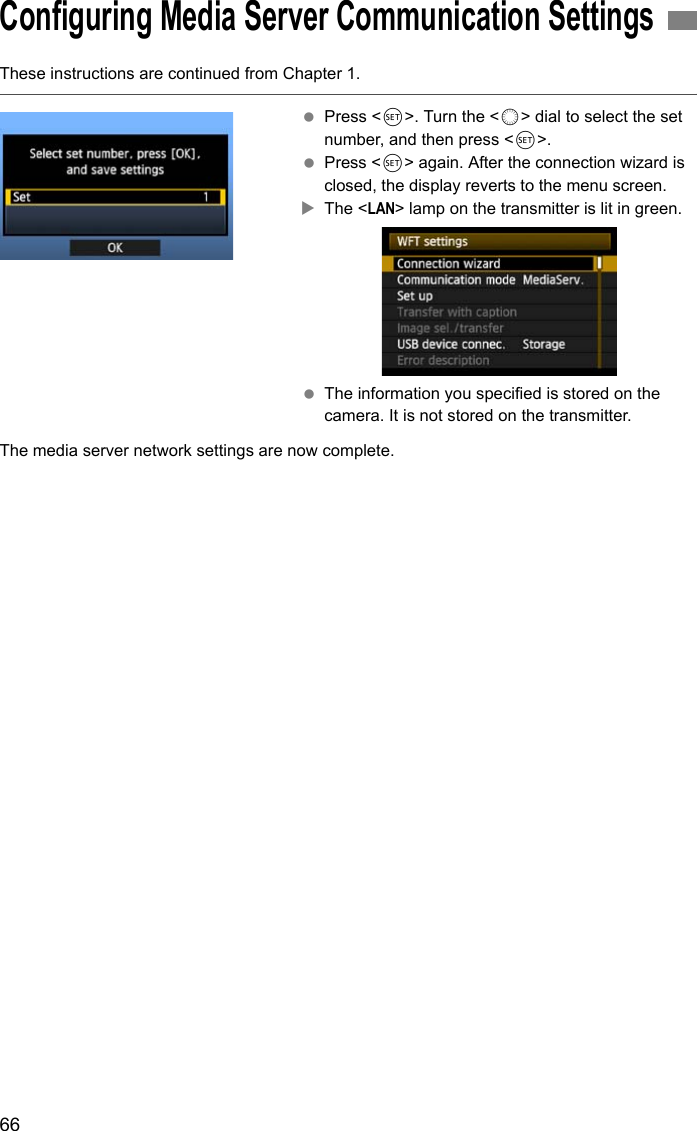
![54These instructions are continued from Chapter 1. Press <0>. Turn the <5> dial to select the set number, and then press <0>. Press <0> again. After the connection wizard is closed, the display reverts to the menu screen.XThe <LAN> lamp on the transmitter is lit in green. Settings information is stored on the camera. It is not stored on the transmitter.Enter a logon name and password for accessing the camera from a computer. The logon name and password you specify here are used on the computer when connecting to the camera.1 Turn the <5> dial to select [Set up], and then press <0>.2 Turn the <5> dial to select [WFT server settings], and then press <0>.Configuring WFT Server Communication SettingsSetting up an Account](https://usermanual.wiki/Canon/161.Manual-3/User-Guide-1142082-Page-8.png)
![55Configuring WFT Server Communication Settings3 Turn the <5> dial to select [WFT account], and then press <0>. When changing the port number, turn the <5> dial to select [Port number] and press <0>. Note that there is normally no need to change the port number (80). 4 Select a user number. With WFT Server, you can connect the camera to up to three computers. Here, select a user number to prevent conflicts when users at other computers are connected to the transmitter simultaneously. Turn the <5> dial to select [User *], and then press <0>.5 After you select [Login name] and [Password], the following input screen is displayed. For instructions on input screen operations, refer to “Virtual Keyboard Operation” (p.31).The WFT Server network settings are now complete.](https://usermanual.wiki/Canon/161.Manual-3/User-Guide-1142082-Page-9.png)
![56In the web browser, display WFT Server, a screen for transmitter operations. Make sure you have already established a connection between the camera and computer.1Start the web browser. First, start Internet Explorer or another web browser.2Enter the URL. In the address field, enter the IP address assigned to the camera. Press the <Enter> key.3Complete the [Login name] and [Password] settings. Enter the login name and password as specified in the procedure on page 55. Click [OK] to display the WFT Server screen. Web browsers that support JavaScript now display the screen on the left below step 4.Otherwise, a message is displayed if JavaScript is not supported. Choosing not to use JavaScript will display the screen on the right below step 4, with limited functions.4Select the language. Select a language at the bottom of the screen.Displaying WFT ServerJavaScript supported JavaScript not supportedIf you don’t know the URL (IP address)You can check the URL (IP address) by accessing [Confirm settings] in the menu (p.74).](https://usermanual.wiki/Canon/161.Manual-3/User-Guide-1142082-Page-10.png)
![57Browse images on the camera’s CF card as follows.1Click [View].XThe image viewing screen is displayed.2Select the memory card. Click [CF] or the external media. Click the [DCIM] folder and select the folder containing the images.3Select an image. To view another image, click the < > buttons or jump to other pages. In JavaScript-compatible web browsers, you can specify how many thumbnails are shown per screen by clicking the pull-down list in the upper-right corner of the screen.Viewing Images](https://usermanual.wiki/Canon/161.Manual-3/User-Guide-1142082-Page-11.png)
![58Viewing Images4Download images to the computer. Click a thumbnail.XThe image is displayed at a larger size. To download the image to your computer, click <>. Click [Return] to return to the image viewing screen.Although actual RAW images and movies are not displayed here, they can be downloaded to the computer the same way as JPEGs.](https://usermanual.wiki/Canon/161.Manual-3/User-Guide-1142082-Page-12.png)
![59Remote capture of movies is not supported. Set the camera’s Live View shooting/Movie shooting switch to Live View shooting before capture.For web browsers that do not support JavaScript, refer to page 63, “Remote Capture.” 1Click [Capture (Advanced)].XThe advanced capture screen is displayed.* Shaded items cannot be configured via WFT Server. ②, ④, and ⑫ are configured on the camera itself.Remote Capture [Capture (Advanced)]①Battery check ⑪Quality②Drive mode ⑫Shooting mode③Possible shots ⑬White balance④AF mode ⑭Metering mode⑤Release button ⑮Menu⑥AF/MF switch ⑯Live View shooting button⑦Shutter speed ⑰Manual focus button⑧Aperture ⑱Live View image size switching button⑨ISO speed ⑲Live View image screen⑩Exposure compensation①⑯②③④ ⑤⑥⑦⑧⑨⑩⑪⑫⑬⑭⑮⑰⑱⑲](https://usermanual.wiki/Canon/161.Manual-3/User-Guide-1142082-Page-13.png)
![60Remote Capture [Capture (Advanced)]2Set the lens focus mode switch to <f>. Under these conditions, click the release button (⑤). When you let go of the mouse button, the camera autofocuses and shoots. (See step 5.) With One-Shot AF, the camera does not shoot unless focus is achieved. Try following the next steps to display Live View image and shoot after manually focusing.3Display Live View image. Click the Live View shooting button (⑯).XThe AF/MF switch (⑥) is set to <g>, and Live View image is displayed. If Live View image is not displayed, enable Live View shooting in the menu (⑮). To make Live View image display more responsive, click the Live View image size switching button (⑱). Live View image is now displayed at a smaller size, improving responsiveness. To restore the original size, click this button again.4Manually adjust the focus. Click the buttons < >, < >, < >, < >, < >, and < > to adjust the focus. Note that autofocus is not supported during Live View image display. To focus more closely, click < >, < >, or < >. To focus farther away, click < >, < >, or < >. Three levels of focus adjustment are available. < > < > : Largest increment< > < > : Intermediate increment< > < > : Smallest increment⑯⑱](https://usermanual.wiki/Canon/161.Manual-3/User-Guide-1142082-Page-14.png)
![61Remote Capture [Capture (Advanced)]5Configure the shooting settings. Click setting items (such as quality) to view the setting details, which you can configure. Complete the settings as needed.6Take the picture. Click the release button (⑤). When you let go of the mouse button, the camera shoots.XThe captured image is now displayed. Captured images are stored on the CF card. To download images to your computer, refer to page 57, and use the [View] function.The Live View image may freeze when shooting if the camera is accessed by multiple computers.](https://usermanual.wiki/Canon/161.Manual-3/User-Guide-1142082-Page-15.png)
![62Remote capture of movies is not supported. Set the camera’s Live View shooting/Movie shooting switch to Live View shooting before capture.For web browsers that do not support JavaScript, refer to page 63, “Remote Capture.” 1Click [Capture (Basic)].XThe basic capture screen is displayed, and Live View image is displayed.2Manually adjust the focus. Set the lens focus mode switch to <f>. Click the buttons < >, < >, < >, < >, < >, and < > to adjust the focus.3Take the picture. Click the release button. When you let go of the mouse button, the camera shoots.XThe captured image is now displayed. Captured images are stored on the CF card. To download images to your computer, refer to page 57, and use the [View] function.Remote Capture [Capture (Basic)]Live View image screenRelease button Manual focus button< > < > < >: Focuses more closely< > < > < >: Focuses farther awayLevels of focus adjustment< > < > : Largest increment< > < > : Intermediate increment< > < > : Smallest increment](https://usermanual.wiki/Canon/161.Manual-3/User-Guide-1142082-Page-16.png)
![63The following instructions are for remote capture with web browsers that do not support JavaScript.Remote capture of movies is not supported. Set the camera’s Live View shooting/Movie shooting switch to Live View shooting before capture.1Click [Capture].XThe capture screen is displayed. Live View image is not displayed.2Take the picture. Set the lens focus mode switch to <g>. Adjust the focus on the camera. Click the release button. When you let go of the mouse button, the camera shoots.XThe captured image is now displayed. Captured images are stored on the CF card.3Download images to the computer. Click the image.XThe image is displayed at a larger size. To download the image to your computer, click <>. Click [Return] to return to the capture screen.Although actual RAW images are not displayed here, they can be downloaded to the computer the same way as JPEGs.Remote CaptureScreenRelease button](https://usermanual.wiki/Canon/161.Manual-3/User-Guide-1142082-Page-17.png)


![70First, establish a connection from the slave cameras to the master camera. Because linked shooting utilizes a wireless connection via IEEE 802.11g in ad hoc mode, it is not available over wired LANs. 1Display the transmitter menu. On the camera, press the <7> button. On the [5] tab, select [WFT settings] and press <0>. [WFT settings] is added to the tab after you attach the transmitter. 2Select [Connection wizard]. 3Select [LinkedShot].4Set up the slave cameras. Select [Slave]. XThe slave cameras are now ready, with the following screen displayed. When using multiple slave cameras, set up all slave cameras to slave state. Once the settings are complete, slaves cannot be added or removed. You must repeat the setup process from step 1. Setting Up Linked Shooting](https://usermanual.wiki/Canon/161.Manual-3/User-Guide-1142082-Page-24.png)
![71Setting Up Linked Shooting5Set up the master camera. Configure the settings on the master camera following steps 1-3 on the previous page, and then select [Master]. XThe following screen is displayed.6At this point, switch to setting up the slave cameras. On the slave cameras, select [OK]. 7Check the number of slave cameras. XOn the master camera LCD monitor, the number of slave cameras detected is displayed. 8Establish the connection. On the master camera and all slave cameras, select [OK]. XA screen is displayed as the connection is tested. The information you specified is stored on the cameras. It is not stored on the transmitters.](https://usermanual.wiki/Canon/161.Manual-3/User-Guide-1142082-Page-25.png)
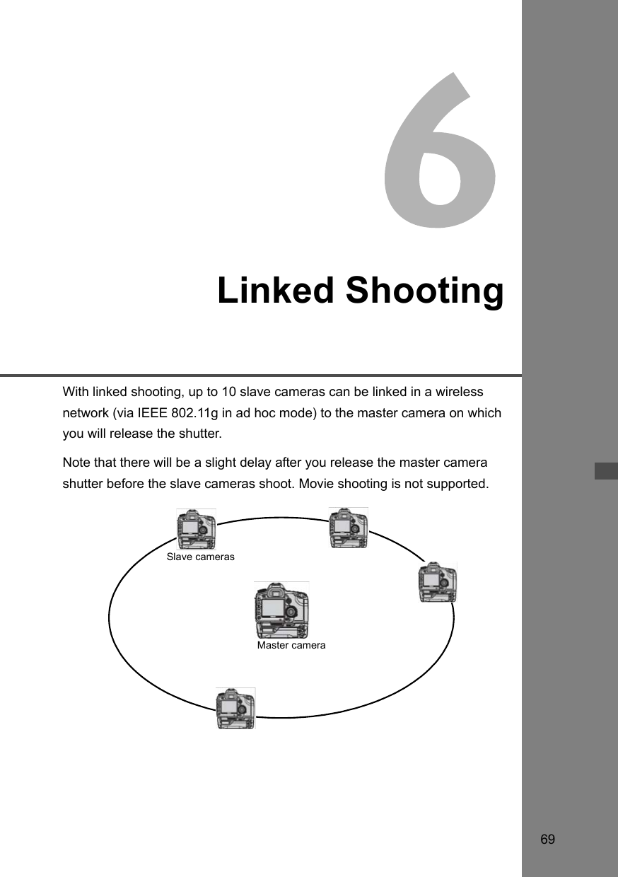
![72 Arrange the slave cameras in clear view of the master camera, without objects between them. You can arrange slave cameras in an overall circumference of up to approximately 150 m / 492 ft. However, the distance supported for linked shooting may be shorter depending on the wireless communication conditions, which are affected by how the cameras are arranged, the environment of use, and weather conditions. There will be a slight delay after you release the master camera shutter until the slave camera shutters are released. (Simultaneous capture is not possible.) Arranging the Slave CamerasMaster cameraSlave cameras Once you have established a connection between the master camera and slave cameras, the settings are retained even after you replace the batteries. If you will no longer use a slave camera in linked shooting, set [Communication mode] to [Disconnect] on that slave camera.](https://usermanual.wiki/Canon/161.Manual-3/User-Guide-1142082-Page-26.png)
![74Check the network settings as follows.1In [WFT settings], select [Set up].2 Select [Confirm settings].XThe settings are displayed.Checking SettingsExample of FTP transfer and wired LAN settingsExample of FTP transfer and wireless LAN settings](https://usermanual.wiki/Canon/161.Manual-3/User-Guide-1142082-Page-28.png)
![75Settings originally completed using the connection wizard can be changed as follows. You can also change IP security settings (IPsec) not completed using the connection wizard, as well as other settings, such as the setting that determines what happens if an image of the same file name as an existing file is sent to the FTP server. (p.76)1In [WFT settings], select [Set up].2Select [LAN settings].3Select the settings number. Here, select the settings number that identifies the LAN settings.4Select [Change]. After selecting [Change settings name], you can rename the settings.5Select the item to change. Select the desired item from [LAN type], [TCP/IP], [FTP server], or [Wireless LAN] and change the setting.Changing Settings](https://usermanual.wiki/Canon/161.Manual-3/User-Guide-1142082-Page-29.png)
![76Changing SettingsConfigured in [TCP/IP] [Security].IPsec is a set of standards for encrypted communication over the Internet. It provides effective security for both wireless and wired LANs. To use this function, you must enable IPsec in the network settings of your computer. When IPsec is employed, only transport mode is supported, and DES encryption and SHA1 authentication are used. Note that the IP address of the computer for communication with the transmitter must be entered in [Destination address] on the settings screen.Configured in [FTP server] [Directory structure].Selecting [Camera] automatically creates a folder structure matching that of the camera’s (such as A/DCIM/100EOS7D) in the server’s root folder for image storage. If you have created a subfolder in the root folder by changing the [Target folder] setting, a folder structure such as A/DCIM/100EOS7D is automatically created in that folder for image storage.Selecting [Default] will use the root folder for image storage. If you have created a subfolder in the root folder by changing the [Target folder] setting, images are saved in that folder.Configured in [FTP server] [Overwrite same file].When the transmitter is configured to prevent overwritingIf there is already a file of the same name in the target folder on the FTP server, the new file is saved with an extension consisting of an underline and a number, as in IMG_0003_1.JPG.When you resend images if initial transfer failsEven if the transmitter is configured to overwrite files of the same name, if you resend an image file that could not be transferred initially, the existing file may not be overwritten in some cases. If this happens, the new file is saved with an extension consisting of an underline, a letter, and a number, as in IMG_0003_a1.JPG.Configured in [FTP server] [Passive mode].Enable this setting in network environments protected by a firewall. If an Error 41 occurs (“Cannot connect to FTP server”), setting passive mode to [Enable] may enable access to the FTP server.To prevent accidental changes to LAN settings, set [Protect settings] to [On].IP Security (IPsec)Directory Structure of the Target FolderOverwriting Files of the Same NamePassive ModePreventing Changes to Settings](https://usermanual.wiki/Canon/161.Manual-3/User-Guide-1142082-Page-30.png)
![77Network settings can be saved on a CF card for use with other cameras.1In [WFT settings], select [Set up].2Select [LAN settings].3Select the settings number. Here, select the settings number that identifies the LAN settings.4Select [Change].5Select [Save settings].Saving and Loading SettingsSaving Settings](https://usermanual.wiki/Canon/161.Manual-3/User-Guide-1142082-Page-31.png)
![78Saving and Loading Settings6Select [Save].XThe settings are now saved as a file on the CF card. The settings are saved as a file (WFTNPF**.NIF) in the area of the CF card shown when the card is opened (in the root directory). The file name is determined automatically by the camera: WFTNPF, followed by a number (01 to 99) and the extension NIF. You can rename the file as desired by selecting [Change file name].Load settings files stored on a CF card as follows. Also use this procedure when loading settings files created on a computer.Make sure the settings file is saved in the folder shown when the CF card is opened (that is, the root directory).1Select [Load settings].2Select the settings file.XSelect a settings file that matches your network environment.3Load the settings file.XInformation from the settings file is loaded into the selected settings number.Loading Settings](https://usermanual.wiki/Canon/161.Manual-3/User-Guide-1142082-Page-32.png)
![80Before connecting external media to the transmitter, switch the camera’s power switch to <OFF>. Also turn off external media that has its own power supply.When connecting external media, be sure to use the USB cable provided with the camera.The transmitter USB port is not hot-pluggable. USB cables cannot be connected or disconnected at any time. Follow the instructions in this section when connecting or disconnecting USB cables.1Plug the external media into the USB port. Open the port cover and connect the external media. Do not connect external media via a USB hub. If the external media is self-powered, turn it on after connecting it.2In [WFT settings], select [USB device connec.]. If you will not use a wireless or wired LAN at the same time as the external media, set [Communication mode] to [Disconnect].3Select [Storage].4Select [Connect].Connecting External MediaWhen replacing the transmitter’s battery, be sure to first set the camera’s power switch to <OFF>before opening the transmitter’s battery compartment cover. If the transmitter’s battery compartmentcover is opened without setting the camera’s power switch to <OFF>, the connection operation for theexternal media will have to be performed again.](https://usermanual.wiki/Canon/161.Manual-3/User-Guide-1142082-Page-34.png)
![81Connecting External Media5Select [OK]. Camera operations such as shooting, menu display, or image playback are not possible until the connection is established. When the transmitter is connected to the external media, the transmitter’s <USB> lamp is lit in green and a message is displayed indicating that a connection has been established. When the confirmation message is displayed, select [OK].XAt this point, the menu option [Disconnect] becomes available. Select this option before disconnecting the external media.XAfter you exit the menu, the rear LCD panel indicates that external media is connected.External media cannot be formatted using the camera. Format it with a FAT16 or FAT32 file system using the computer.](https://usermanual.wiki/Canon/161.Manual-3/User-Guide-1142082-Page-35.png)
![82Connecting External MediaBefore unplugging external media from the USB port, always select [Disconnect] as shown in step 5. Follow the instructions displayed to terminate the connection.The connection will not be terminated if you simply turn off the camera and external media. If you unplug external media while the connection is still active, plug the external media into the USB port again and follow the preceding steps to terminate the connection.External media is powered via the transmitter’s USB port as needed. However, external hard disk drives may not work after connection in some cases.Power Management If you will not use a wireless or wired LAN at the same time as the external media, set [Communication mode] to [Disconnect]. The camera battery drains faster under settings other than [Disconnect] because power saving is disabled. Setting [Power saving] to [Enable] enables the power supply to external media to be stopped automatically, conserving the camera battery. Power is supplied again automatically during shooting, when captured images are stored.Unplugging External Media from the USB PortPower Supply to External MediaBefore shooting movie, set [Power saving] to [Disable] and make sure the transmitter’s <USB> lamp is lit in green. If you start shooting movie when the <USB> lamp is out or blinking, the movie may not be recorded to external media.](https://usermanual.wiki/Canon/161.Manual-3/User-Guide-1142082-Page-36.png)
![83Images can be recorded to external media connected via USB. This enables recording of images to external media without loading the CF card into the camera.You can also create your own DCIM folders for storing images in the external media.When recording movies to a hard disk, use a hard disk with fast writing specifications.1On the [5] tab, select [Recording func.+media select]. 2Select [u] (external media) under [Record/play].XThe [DCIM location] screen is displayed. The DCIM folder is the folder for storing images. Select the initial setting of [/] and press the <7> button to create a DCIM folder where the external media is opened (that is, root directory). When images are taken, they will be stored in the DCIM folder of the external media.3Select the recording quality.The recording quality when external media is selected is set to the same recording quality as the CF card.The recording quality can be changed with [Quality] on the [1] tab.Choosing Recording Media When ShootingAlthough the <USB> lamp will blink in green briefly if the camera is turned off and on or recovering fromauto power off, shooting (except shooting movie) is still possible. Any images captured at this time arestored temporarily in the camera’s internal memory and then recorded on external media when the<USB> lamp remains lit in green.](https://usermanual.wiki/Canon/161.Manual-3/User-Guide-1142082-Page-37.png)
![84Choosing Recording Media When ShootingSelecting [Create folder] enables the user to create a folder in the external media for storing the DCIM folder. This is useful for separating DCIM folders by shooting dates, for instance.1Select [Create folder]. 2Check the folder name. By default, the folder name comprises the current date (last two digits of the year, in addition to the month and day) and numbers representing the order the folder was created, in a range of 01 to 99. If the folder name is OK, press the <7> button.XThe created folder is selected. When changing the folder name, always use an eight-character name. For instructions on entering the folder name, refer to “Virtual Keyboard Operation” (p.31). Using [Create folder]Erasing ImagesAlthough “Erase all images on external media (except K images)” is displayed when [Erase images] [All images on card] on the [3] tab is selected, what are actually erased are all images in [DCIM location] folders, as described above.](https://usermanual.wiki/Canon/161.Manual-3/User-Guide-1142082-Page-38.png)
![85When using external media connected via USB and a CF card loaded in the camera at the same time, various types of image recordings can be made. Note that the settings made in [Record func.] below are disabled in the Full Auto and Creative Auto modes.1On the [5] tab, select [Recording func.+media select]. 2Select [Record func.]. Select the setting based on “[Record func.] Options” below. The recording quality is selected with [Quality] on the [1] tab. StandardImages are recorded to the media selected in [Record/play]. Auto switch mediaImages are recorded to the media selected in [Record/play], and when there is no more free space, the recording of images is automatically switched to the other media. Rec. separatelyWhenever an image is taken, it is recorded to both the CF card and external media. Selecting [Quality] on the [1] tab enables selection of a separate recording image quality for the CF card and external media. Making this setting displays the image quality recorded to the external media on the transmitter’s LCD panel. Rec. to multipleWhenever an image is captured, the same image is recorded to both the CF card and external media. [Rec. to multiple] is not available for movies. Movies are recorded to media selected in [Record/play]. Using Together With a CF Card[Record func.] Options](https://usermanual.wiki/Canon/161.Manual-3/User-Guide-1142082-Page-39.png)
![86Images recorded on the CF card can be backed up to external media.1On the [3] tab, select [External media backup].2Select the method of backup.3Check the free space on the media. In [Quick backup] and [Backup], make sure that the available space on the external media is larger than the amount used on the CF card. If less free space is available on the external media, backup is not possible.Backing Up on External Media External media cannot be backed up onto CF cards. If the backup destination already has a folder of the same number containing images of the same file number, [Skip image and continue], [Replace existing image], and [Cancel backup] are displayed. Select the backup method and press <0>.•[Skip image and continue]: All images are backed up except for images of the same file number as existing images•[Replace existing image]: All images are backed up, including images of the same file number as existing images Shooting is not possible during backup. Press [Cancel] before shooting.](https://usermanual.wiki/Canon/161.Manual-3/User-Guide-1142082-Page-40.png)
![87Backing Up on External MediaA simple method of backup is available. In [Quick backup], a folder with the current date is automatically created where the external media is opened (that is, root directory), and the DCIM folder containing the recorded images is stored inside this folder.1Select [Quick backup].2Select [OK].XThe backup process now begins. When the message indicating completion is displayed, select [OK].Where the DCIM Folder is Stored The DCIM folder is stored in a directory indicated by a file path such as [u/09083101/]. The target folder name comprises the current date (last two digits of the year, in addition to the month and day) and numbers representing the order the folder was created, in a range of 01 to 99. In the example shown at left, the folder displayed when the external media is opened (that is, the root directory) is named 09083101. The DCIM folder is stored in this folder. This is also the target folder name displayed when using the regular [Backup] option.Quick Backup](https://usermanual.wiki/Canon/161.Manual-3/User-Guide-1142082-Page-41.png)
![88Backing Up on External MediaIn [Backup], you can create a folder for backup in external media as desired, and save the DCIM folder where images are stored in the selected folder. You can also name this folder as desired. Other functions in this method of backup are the same as for [Quick backup].1Select [Backup].2Select [OK].3Select [Create folder].4Enter the [Folder name]. Always use 8 characters for the folder name. For instructions on entering the folder name, refer to “Virtual Keyboard Operation” (p.31).Backup](https://usermanual.wiki/Canon/161.Manual-3/User-Guide-1142082-Page-42.png)
![89Backing Up on External Media5Select [OK].XThe backup process now begins. When the message indicating completion is displayed, select [OK].Only the necessary images can be selected for backup to external media.1Select [Backup selected images]. 2Select the images for backup. Turn the <5> dial to select the image, and then press <0>.X<X> is displayed at the top left of the image to be backed up. Press the <y> button to display three images per screen. Press the <u> button to display one image per screen again. After the images for backup are selected, press the <A> button.XSelect [OK] in the displayed screen.Selecting Images for Backup](https://usermanual.wiki/Canon/161.Manual-3/User-Guide-1142082-Page-43.png)
![90Backing Up on External Media3Select [/], and then press the <7> button.XSelect [OK] in the displayed screen.XBackup of the images will be started. The images are stored into the DCIM folder created where the external media is opened (that is, root directory). When backing up to a selected folder in external media, select [Create folder]. For details, see steps 3 and 4 on page 88.](https://usermanual.wiki/Canon/161.Manual-3/User-Guide-1142082-Page-44.png)
![92Turn off the GPS device and camera before connecting them.When connecting GPS devices, be sure to use the USB cable provided with the camera.The transmitter USB port is not hot-pluggable. USB cables cannot be connected or disconnected at any time. Follow the instructions in this section when connecting or disconnecting USB cables.1Plug the GPS device into the USB port. Open the port cover and connect the GPS device. Do not connect GPS device via a USB hub. Do not turn the GPS device on until step 5.2In [WFT settings], select [USB device connec.]. If you will not use a wireless or wired LAN at the same time as the GPS device, set [Communication mode] to [Disconnect].3Select [GPS].4Select [Connect].Connecting GPS Devices with a USB CableWhen replacing the transmitter’s battery, be sure to first set the camera’s power switch to <OFF>before opening the transmitter’s battery compartment cover. If the transmitter’s battery compartmentcover is opened without setting the camera’s power switch to <OFF>, the connection operation for theGPS device will have to be performed again.](https://usermanual.wiki/Canon/161.Manual-3/User-Guide-1142082-Page-46.png)
![93Connecting GPS Devices with a USB Cable5Select [OK]. After selecting [OK], turn the GPS device on. It may take a few minutes to establish a connection with the GPS device. Camera operations such as shooting, menu display, or image playback are not possible until the connection is established. When the transmitter is connected to the GPS device, the transmitter’s <USB> lamp is lit in green and a message is displayed indicating that a connection has been established. When the confirmation message is displayed, select [OK].XAt this point, the menu option [Disconnect] becomes available. Select this option before disconnecting the GPS device.6Take the picture. Make sure the transmitter’s <USB> lamp is lit in green before shooting. If the <USB> lamp is not lit in green when you shoot, correct GPS data will not be added to images.7Check the GPS data. View an image. Press the <6> button to display the shooting information screen with GPS data.From top to bottom: latitude, longitude, altitude, and Coordinated Universal TimeThe date and time indicated is the Coordinated Universal Time (UTC) as obtained by the GPS device, which is nearly the same as Greenwich Mean Time (GMT). In some cases, the date and time of the zone specified on the GPS device is indicated.If the camera is turned off and on or recovering from auto power off, do not shoot until the <USB> lamp remains lit in green. If you shoot while the lamp is blinking, the correct GPS information may not be added to images.](https://usermanual.wiki/Canon/161.Manual-3/User-Guide-1142082-Page-47.png)
![94Connecting GPS Devices with a USB CableBefore unplugging GPS devices from the USB port, always select [Disconnect] as shown in step 5. Follow the instructions displayed to terminate the connection.The connection will not be terminated if you simply turn off the camera and GPS device. If you unplug GPS device while the connection is still active, plug the GPS device into the USB port again and follow the preceding steps to terminate the connection. If you will not use a wireless or wired LAN at the same time as the GPS device, set [Communication mode] to [Disconnect]. The camera battery drains faster under settings other than [Disconnect] because power saving is disabled.Unplugging GPS Devices from the USB PortPower Management](https://usermanual.wiki/Canon/161.Manual-3/User-Guide-1142082-Page-48.png)
![95By attaching the Canon Bluetooth Unit BU-30 to the USB port, you can connect Bluetooth® GPS devices wirelessly. (Bluetooth® devices other than GPS devices cannot be connected). When using non-Canon Bluetooth units, confirm normal operation before use.Turn off the GPS device and camera before attaching the Bluetooth unit to the transmitter.The transmitter’s USB port is not hot-pluggable. Bluetooth units cannot be connected or disconnected indiscriminately. Follow the instructions in this section when attaching or detaching Bluetooth units.1Attach the Bluetooth unit. Open the port cover and attach the Bluetooth unit.2In [WFT settings], select [USB device connec.] If you will not use a wireless or wired LAN at the same time as the Bluetooth unit, set [Communication mode] to [Disconnect].3Select [Bluetooth].4Select [Connect].Connecting GPS Devices via BluetoothWhen replacing the transmitter battery, always set the camera’s power switch to <OFF> before opening the transmitter battery compartment cover. If the transmitter battery compartment cover is opened without setting the camera’s power switch to <OFF>, you will need to reestablish the connection to the Bluetooth unit.](https://usermanual.wiki/Canon/161.Manual-3/User-Guide-1142082-Page-49.png)
![96Connecting GPS Devices via Bluetooth5Select [OK]. After the Bluetooth unit is attached to the transmitter, the transmitter’s <USB> lamp blinks in green and a message is displayed indicating that a connection has been established. When the confirmation message is displayed, select [OK].XAt this point, the menu option [Disconnect] becomes available. Select this option before detaching the GPS device.6Establish a wireless connection between the GPS device and Bluetooth unit. Turn on the GPS device and activate Bluetooth® on it. Select [Bluetooth device connection].XNearby Bluetooth® devices in use are listed. (Only GPS devices can be connected.) 7Select the GPS device. Press <0> to display the connection status of Bluetooth® devices. Pressing <0> when the status is [Not connected] will list nearby Bluetooth® devices in use. Turn the <5> dial to select [GPS] , and then press <0>. Select [OK] and press <0>. If a Bluetooth® password has been set on the GPS device, a password input screen is displayed. Enter the password.XThe transmitter now starts to establish a connection with the GPS device. It may take a few minutes to establish a connection with the GPS device.Camera operations such as shooting, menu display, or image playback are not possible until the connection is established.](https://usermanual.wiki/Canon/161.Manual-3/User-Guide-1142082-Page-50.png)
![97Connecting GPS Devices via Bluetooth8When the confirmation message is displayed, select [OK]. The GPS connection status changes to [Connected]. Pressing <0> under these conditions will enable you to disconnect the GPS device9Take the picture. Make sure the transmitter’s <USB> lamp is lit in green before shooting. If the <USB> lamp is not lit in green when you shoot, the correct GPS data will not be added to images.10Check the GPS data. View an image. Press the <6> button to display the shooting information screen with GPS data.From top to bottom: latitude, longitude,altitude, and Coordinated Universal TimeIf the camera is turned off and on or recovering from auto power off, do not shoot until the <USB> lamp remains lit in green. If you shoot while the lamp is blinking, the correct GPS information may not be added to images.The date and time indicated is the Coordinated Universal Time (UTC) as obtained by the GPS device, which is nearly the same as Greenwich Mean Time (GMT). In some cases, the date and time of the zone specified on the GPS device is indicated.](https://usermanual.wiki/Canon/161.Manual-3/User-Guide-1142082-Page-51.png)
![98Connecting GPS Devices via BluetoothBefore detaching Bluetooth units from the USB port, always select [Disconnect] as shown in step 5. Follow the instructions displayed to terminate the connection.The connection with the Bluetooth unit will not be terminated if you simply turn off the camera. If you detach a Bluetooth unit while the connection is still active, attach the Bluetooth unit again and follow the preceding steps to terminate the connection. If you will not use a wireless or wired LAN at the same time as the Bluetooth unit, set [Communication mode] to [Disconnect]. The camera battery drains faster under settings other than [Disconnect] because power saving is disabled.Detaching Bluetooth units from the USB portPower Management](https://usermanual.wiki/Canon/161.Manual-3/User-Guide-1142082-Page-52.png)
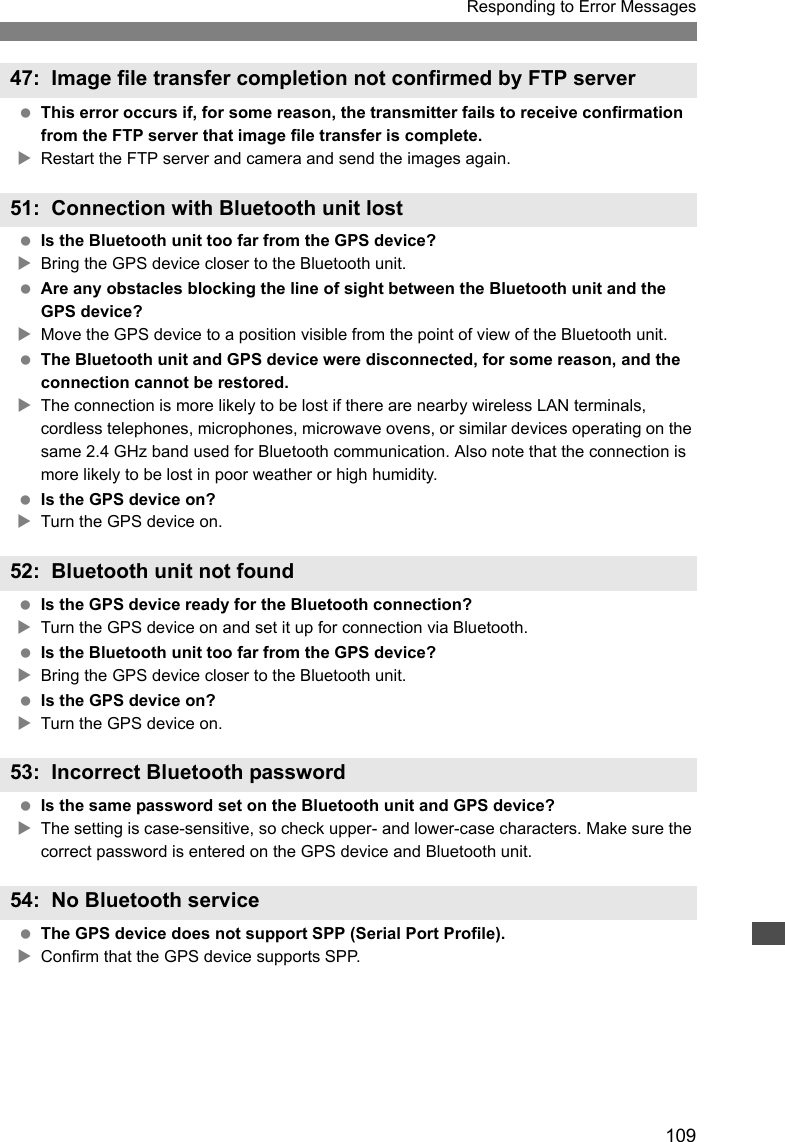
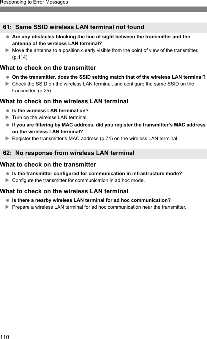
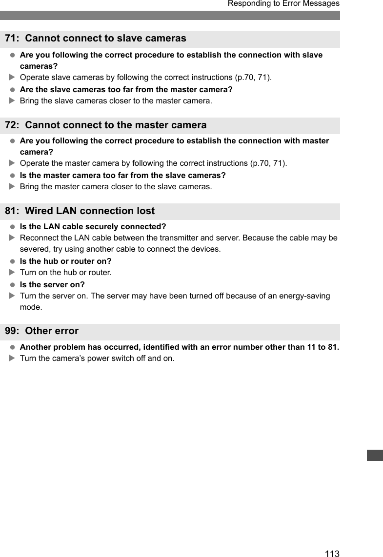
![100If transmitter errors are displayed on the camera LCD monitor, refer to the examples of corrective actions in this section to eliminate the cause of the error. The error details can also be checked on the [5] tab [WFT settings] [Error description].Click the error number in the following chart to jump to the corresponding page.Responding to Error Messages11 (p.101) 12 (p.101)21 (p.101) 22 (p.102) 23 (p.102) 24 (p.103) 25 (p.104)26 (p.104)31 (p.105) 32 (p.105) 33 (p.105) 34 (p.105)41 (p.106) 42 (p.107) 43 (p.107) 44 (p.107) 45 (p.108)46 (p.108) 47 (p.109)51 (p.109) 52 (p.109) 53 (p.109) 54 (p.109)61 (p.110) 62 (p.110) 63 (p.111) 64 (p.111) 65 (p.111)66 (p.112) 67 (p.112) 68 (p.112) 69 (p.112)71 (p.113) 72 (p.113)81 (p.113)99 (p.113)](https://usermanual.wiki/Canon/161.Manual-3/User-Guide-1142082-Page-54.png)
![101Responding to Error Messages Is the pairing software running?XStart the pairing software and follow the instructions to re-establish the connection. (p.48) Are the transmitter and wireless LAN terminal configured with the same encryption key for authentication?XThis error occurs if the encryption keys do not match when the authentication method for encryption is [Open system].The setting is case-sensitive, so check upper- and lower-case characters. Make sure the correct encryption key for authentication is entered on the transmitter. (p.26) Are the target computer and wireless LAN terminal on?XTurn on the target computer and wireless LAN terminal.What to check on the transmitter On the transmitter, the network setting is [Auto setting] or the IP address setting is [Auto assign]. Does the error occur under these settings?XIf no DHCP server is used, set the transmitter’s network setting to [Manual setting] and IP address setting to [Manual setting]. (p.29)What to check on the DHCP server Is the DHCP server on?XTurn the DHCP server on. Are there enough addresses for assignment by the DHCP server?XIncrease the number of addresses assigned by the DHCP server.XRemove devices assigned addresses by the DHCP server from the network to reduce the number of addresses in use. Is the DHCP server working correctly?XCheck the DHCP server settings to make sure it is working correctly as a DHCP server.XIf applicable, ask your network administrator to ensure the DHCP server is available.11: Connection target not found12: Connection target not found21: No address assigned by DHCP serverResponding to Error Messages 21 - 26Also check the following points when responding to errors numbered 21 - 26. Are the transmitter and wireless LAN terminal configured with the same encryption key for authentication? XThis error occurs if the encryption keys do not match when the authentication method for encryption is [Open system]. The setting is case-sensitive, so check upper- and lower-case characters. Make sure the correct encryption key for authentication is entered on the transmitter. (p.26)](https://usermanual.wiki/Canon/161.Manual-3/User-Guide-1142082-Page-55.png)
![102Responding to Error MessagesWhat to check on the transmitter On the transmitter, the DNS address setting is [Auto assign] or [Manual setting]. Does the error occur under these settings?XIf no DNS server is used, set the transmitter’s DNS address setting to [Disable]. (p.29) On the transmitter, does the DNS server’s IP address setting match the server’s actual address?XConfigure the IP address on the transmitter to match the actual DNS server address. (p.29, 115)What to check on the DNS server Is the DNS server on?XTurn the DNS server on. Are the DNS server settings for IP addresses and the corresponding names correct?XOn the DNS server, make sure IP addresses and the corresponding names are entered correctly. Is the DNS server working correctly?XCheck the DNS server settings to make sure the server is working correctly as a DNS server.XIf applicable, ask your network administrator to ensure the DNS server is available.What to check on the network as a whole Does your network include a router or similar device that serves as a gateway?XIf applicable, ask your network administrator for the network gateway address and enter it on the transmitter. (p.29, 115)XMake sure the gateway address setting is correctly entered on all network devices, including the transmitter.What to check on the transmitter Is another device on the transmitter network using the same IP address as the transmitter?XChange the transmitter’s IP address to avoid using the same address as another device on the network. Otherwise, change the IP address of the device that has a duplicate address.XIn network environments with a DHCP server, if the transmitter’s IP address setting is [Manual setting], change it to [Auto assign]. (p.29)22: No response from DNS server23: Duplicate IP address](https://usermanual.wiki/Canon/161.Manual-3/User-Guide-1142082-Page-56.png)
![103Responding to Error MessagesWhat to check on the transmitter The transmitter’s proxy server setting is [Enable]. Does the error occur under this setting?XIf no proxy server is used, set the transmitter’s proxy server setting to [Disable]. (p.34) Do the transmitter’s [Address setting] and [Port No.] settings match those of the proxy server?XConfigure the transmitter’s proxy server address and port number to match those of the proxy server. (p.34) In the transmitter’s [Proxy server] settings, have you only entered [Server name]?XIf the proxy server’s [Address] setting is not configured on the transmitter, enter it along with the DNS server address. (p.29) Make sure the server name and port number for the proxy server are entered correctly. (p.34)What to check on the proxy server Is the proxy server on?XTurn the proxy server on. Is the proxy server working correctly?XCheck the proxy server settings to make sure the server is working correctly as a proxy server.XIf applicable, ask your network administrator for the proxy server address or server name and port number, and then enter them on the transmitter.What to check on the network as a whole Does your network include a router or similar device that serves as a gateway?XIf applicable, ask your network administrator for the network gateway address and enter it on the transmitter.XMake sure the gateway address setting is correctly entered on all network devices, including the transmitter.24: No response from proxy server](https://usermanual.wiki/Canon/161.Manual-3/User-Guide-1142082-Page-57.png)
![104Responding to Error Messages Is another device on the transmitter network using the same IP address as the transmitter?XThis error occurs if the transmitter is connected to a network where another device subsequently connects with the same IP address. Change the transmitter’s IP address to avoid using the same address as another device on the network. Otherwise, change the IP address of the device that has a duplicate address.What to check on the transmitter On the transmitter, the network setting is [Auto setting]. Does the error occur under this setting?XIf no DHCP server is used, set the transmitter’s network setting to [Manual setting]. (p.29)What to check on the DHCP server Is the DHCP server on?XTurn the DHCP server on. Are the DHCP server settings for IP addresses and the corresponding names correct?XOn the DHCP server, make sure IP addresses and the corresponding names are entered correctly. Is the DHCP server working correctly?XCheck the DHCP server settings to make sure it is working correctly as a DHCP server.XIf applicable, ask your network administrator to ensure the DHCP server is available.What to check on the network as a whole Does your network include a router or similar device that serves as a gateway?XIf applicable, ask your network administrator for the network gateway address and enter it on the transmitter. (p.29)XMake sure the gateway address setting is correctly entered on all network devices, including the transmitter.25: Another terminal has set the same IP address26: No response from DHCP server](https://usermanual.wiki/Canon/161.Manual-3/User-Guide-1142082-Page-58.png)
![105Responding to Error Messages Has the USB cable been disconnected?XAfter connecting the USB cable, in [WFT settings], select [USB device connec.] and reconnect the device. Is the USB device on?XTurn the USB device on. Next, also in [WFT settings], select [USB device connec.] and reconnect the device. Have you connected a USB device other than external media, a GPS device, or a Bluetooth unit? XConnect only external media, GPS devices, or Bluetooth units. The device is incompatible with the transmitter.XExternal media with built-in card slots are not compatible. Similarly, USB card readers cannot be used. Is the external media formatted with a FAT16 or FAT32 file system?XFormat the external media with a FAT16 or FAT32 file system using the computer. The GPS device is incompatible with the transmitter.XAmong GPS devices, we recommend devices for which operation has been verified by Canon. There is a problem with the external media.XConnect the external media to a computer and confirm that it is working correctly. Have you connected a USB device other than external media, a GPS device, or a Bluetooth unit? XConnect only external media, GPS devices, or Bluetooth units.31: USB connection disconnected32: Incompatible USB device33: USB device error34: Cannot connect to USB device](https://usermanual.wiki/Canon/161.Manual-3/User-Guide-1142082-Page-59.png)
![106Responding to Error MessagesWhat to check on the transmitter On the transmitter, does the FTP server’s IP address setting match the server’s actual address?XConfigure the IP address on the transmitter to match the actual FTP server address. (p.34) Are the transmitter and wireless LAN terminal configured with the same encryption key for authentication?XThis error occurs if the encryption keys do not match when the authentication method for encryption is [Open system].The setting is case-sensitive, so check upper- and lower-case characters. Make sure the correct encryption key for authentication is entered on the transmitter. (p.26) On the transmitter, does the [Port number setting] for the FTP server match the actual port number of the FTP server?XConfigure the same port number (usually 21) on the transmitter and FTP server. Configure the port number on the transmitter to match the actual FTP server port number. (p.34) If only the FTP server’s [Server name] is configured on the transmitter, are the DNS server settings complete?XIf the FTP server’s [Address] setting is not configured on the transmitter, enable use of the DNS server on the transmitter and enter its address. (p.29) Make sure the FTP server name is entered correctly. (p.34)What to check on the FTP server Is the FTP server working correctly?XConfigure the computer correctly to function as an FTP server.XIf applicable, ask your network administrator for the FTP server address and port number, and then enter them on the transmitter. Is the FTP server on?XTurn the FTP server on. The server may have been turned off because of an energy-saving mode. On the transmitter, does the FTP server’s IP address setting (in [Address]) match the server’s actual address?XConfigure the IP address on the transmitter to match the actual FTP server address. (p.34) Is a firewall or other security software enabled?XSome security software uses a firewall to restrict access to the FTP server. Change the firewall settings to allow access to the FTP server.XYou may be able to access the FTP server by setting [Passive mode] to [Enable] on the transmitter. (p.76)41: Cannot connect to FTP server](https://usermanual.wiki/Canon/161.Manual-3/User-Guide-1142082-Page-60.png)
![107Responding to Error Messages Are you connecting to the FTP server via a broadband router?XSome broadband routers use a firewall to restrict access to the FTP server. Change the firewall settings to allow access to the FTP server.XYou may be able to access the FTP server by setting [Passive mode] to [Enable] on the transmitter. (p.76) If you are using Windows XP Service Pack 2 or later, is access to the FTP server blocked by [Windows Firewall]? XChange the Windows Firewall settings to allow access to the FTP server.What to check on the network as a whole Does your network include a router or similar device that serves as a gateway?XIf applicable, ask your network administrator for the network gateway address and enter it on the transmitter. (p.29)XMake sure the gateway address setting is correctly entered on all network devices, including the transmitter.What to check on the FTP server Is the FTP server configured to restrict access to only some IP addresses?XChange the FTP server settings to allow access from the [IP address] configured on the transmitter in the TCP/IP settings.What to check on the FTP server Have you exceeded the maximum number of FTP server connections?XDisconnect some network devices from the FTP server or increase the maximum number of connections. This error occurs if the transmitter fails to disconnect from the FTP server for some reason.XRestart the FTP server and camera.42: FTP server rejected connection43: Cannot connect to FTP server. Error code received from server. 44: Cannot disconnect FTP server. Error code received from server.](https://usermanual.wiki/Canon/161.Manual-3/User-Guide-1142082-Page-61.png)
![108Responding to Error MessagesWhat to check on the transmitter On the transmitter, is the [Login name] entered correctly?XCheck the logon name for accessing the FTP server. The setting is case-sensitive, so check upper- and lower-case characters. Make sure the correct logon name is entered on the transmitter. (p.35) On the transmitter, is the [Login password] entered correctly?XIf a logon password is configured on the FTP server, check the upper- and lower-case characters to make sure the password on the transmitter matches it. (p.35)What to check on the FTP server Do the user rights for the FTP server allow reading, writing, and log access?XConfigure the FTP server’s user rights to allow reading, writing, and log access. Is the folder specified as the transfer destination on the FTP server named with ASCII characters (p.31)?XUse ASCII characters for the folder name.What to check on the FTP server The connection was terminated by the FTP server.XRestart the FTP server. Do the user rights for the FTP server allow reading, writing, and log access?XConfigure the FTP server’s user rights to allow reading, writing, and log access. Do user rights allow access to the target folder on the FTP server?XConfigure the user rights for access to the target folder on the FTP server to allow saving images from the transmitter. Is the FTP server on?XTurn the FTP server on. The server may have been turned off because of an energy-saving mode. Is the hard disk of the FTP server full?XIncrease available space on the hard disk.45: Cannot login to FTP server. Error code received from server.46: For the data session, error code received from FTP server](https://usermanual.wiki/Canon/161.Manual-3/User-Guide-1142082-Page-62.png)
![111Responding to Error Messages Are the transmitter and wireless LAN terminal configured for the same authentication method?XThe transmitter supports these authentication methods: [Open system], [Shared key], [WPA-PSK], and [WPA2-PSK]. (p.25)XWhen using an AirPort for communication in infrastructure mode, [Open system] is not supported. Configure a [Shared key] on the transmitter. (p.25) Are the transmitter and wireless LAN terminal configured with the same encryption key for authentication?XThe setting is case-sensitive, so check upper- and lower-case characters. Make sure the correct encryption key for authentication is entered on the transmitter and wireless LAN terminal. (p.26) If you are filtering by MAC address, did you register the transmitter’s MAC address on the wireless LAN terminal?XRegister the transmitter’s MAC address (p.74) on the wireless LAN terminal. Are the transmitter and wireless LAN terminal configured for the same encryption method?XThe transmitter supports these encryption methods: [WEP], [TKIP], and [AES]. (p.25) If you are filtering by MAC address, did you register the transmitter’s MAC address on the wireless LAN terminal?XRegister the transmitter’s MAC address (p.74) on the wireless LAN terminal. Are any obstacles blocking the line of sight between the transmitter and the antenna of the wireless LAN terminal?XMove the antenna to a position clearly visible from the point of view of the transmitter. (p.114) The wireless LAN connection was lost, for some reason, and the connection cannot be restored.XThe following are possible reasons: excessive access to the wireless LAN terminal from other terminals, a microwave oven or similar appliance in use nearby (interfering with IEEE 802.11b/g reception), or poor weather or high humidity. (p.114)63: Wireless LAN authentication failed64: Cannot connect to wireless LAN terminal65: Wireless LAN connection lost](https://usermanual.wiki/Canon/161.Manual-3/User-Guide-1142082-Page-65.png)
![112Responding to Error Messages Are the transmitter and wireless LAN terminal configured with the same encryption key for authentication?XThe setting is case-sensitive, so check upper- and lower-case characters. Make sure the correct encryption key for authentication is entered on the transmitter and wireless LAN terminal. (p.26)Note that if the authentication method is [Open system], an Error 41 (“Cannot connect to FTP server”) is displayed. Are the transmitter and wireless LAN terminal configured for the same encryption method?XThe transmitter supports these encryption methods: [WEP], [TKIP], and [AES]. (p.25) If you are filtering by MAC address, did you register the transmitter’s MAC address on the wireless LAN terminal?XRegister the transmitter’s MAC address (p.74) on the wireless LAN terminal. Have you pressed the Wi-Fi Protected Setup (WPS) button on the wireless LAN terminal for as long as indicated in the wireless LAN terminal instructions?XRefer to the instruction manual for the wireless LAN terminal to determine how long to hold the WPS button. Are you attempting to establish the connection near the wireless LAN terminal?XTry establishing the connection when both devices are within reach of each other. Connection is in progress by other wireless LAN terminals in Pushbutton Connection mode (PBC mode) of Wi-Fi Protected Setup (WPS). XWait a while before trying to establish the connection, or try to establish a connection in PIN code connection mode (PIN mode). (p.28)66: Incorrect wireless LAN encryption key67: Incorrect wireless LAN encryption method68: Cannot connect to wireless LAN terminal. Retry from the beginning.69: Multiple wireless LAN terminals have been found. Cannot connect. Retry from the beginning.](https://usermanual.wiki/Canon/161.Manual-3/User-Guide-1142082-Page-66.png)
![115Click the Windows [Start] button [All Programs] [Accessories] [Command Prompt]. Type ipconfig/all and press the <Enter> key.The IP address assigned to the computer is displayed, as well as the subnet mask, gateway, and DNS server information.To avoid using the same IP address for the computer and other devices on the network when configuring the IP address assigned to the camera (page 29), change the rightmost numbers here.In Mac OS X, open the [Terminal] application, type ifconfig -a, and press the <Return> key. The IP address assigned to the computer is indicated in the [en0] item by [inet], in the format ***.***.***.***.To avoid using the same IP address for the computer and other devices on the network when configuring the IP address assigned to the camera (page 29), change the rightmost numbers here.* For information on the [Terminal] application, refer to the Mac OS X help.Checking Network SettingsWindowsMacintosh](https://usermanual.wiki/Canon/161.Manual-3/User-Guide-1142082-Page-69.png)

![118You can configure the wireless or wired LAN settings by using the software provided with the camera, WFT Utility. This is convenient if you want to create a wireless or wired LAN settings file when the camera and transmitter are not nearby.WFT Utility also enables you to create captions for attachment to images before transfer via FTP.Start WFT Utility from EOS Utility. In EOS Utility, access [Accessories] to start WFT Utility. Click the tabs for the transmitter’s [TCP/IP settings], [FTP settings], and [Wireless LAN settings] and complete the required settings for a wireless or wired LAN connection. Settings available here are the same as settings on the camera, with the addition of settings for creating captions.WFT Utility (Software)Starting WFT UtilityUsing Wireless or Wired LAN Settings](https://usermanual.wiki/Canon/161.Manual-3/User-Guide-1142082-Page-72.png)
![119WFT Utility (Software)When setting the wireless LAN channel on the [Wireless LAN Settings] tab, first select the version of transmitter used. Settings files can be used as follows.Setting the Wireless LAN ChannelWireless or Wired LAN Settings FilesOpen Open a settings file saved on the computer or a CF card. SaveSave the settings file on the computer or a CF card. The [Settings name] is used as the file name.For instructions on applying a settings file on a CF card to the camera, refer to page 78. Load settings from cameraLoad a settings file on the camera to the computer. The camera and computer must be connected with the USB cable. Apply settings to cameraApply the settings file to a camera. The camera and computer must be connected with the USB cable.](https://usermanual.wiki/Canon/161.Manual-3/User-Guide-1142082-Page-73.png)
![120Follow these steps to create captions and register them on the camera, as introduced in “Adding a Caption Before Transfer” (p.39). When creating and registering captions, use a computer on which EOS Utility is installed.Before you begin, attach the transmitter to the camera and use the USB cable provided with the camera to connect the camera to the computer. For instructions on connecting the camera to the computer with the USB cable and starting EOS Utility, refer to the Software Instruction Manual (PDF) provided with the camera. Note that captions cannot be created for cameras without an attached transmitter.1Start EOS Utility and select [Camera settings/Remote shooting].XThe camera settings/remote capture screen is displayed.2On the [ ] tab, select [WFT Captions].XThe screen for caption creation is displayed. To acquire caption data stored on the camera, select [Load settings].3Enter the caption or captions. Enter up to 31 characters (in ASCII format).4Register the captions on the camera. Select [Apply to camera] to register your new captions on the camera.Creating and Registering Captions](https://usermanual.wiki/Canon/161.Manual-3/User-Guide-1142082-Page-74.png)