Carestream Health RVG00002 WiFi and RFID Control Box User Manual SM745 K6500 USER
Carestream Health, Inc. WiFi and RFID Control Box SM745 K6500 USER
Contents
- 1. Manual - Installation
- 2. Manual - Regulatory
Manual - Installation

KODAK RVG 6500 System and KODAK RVG 6500
IPS System
User & Installation Guide
Notice
The User & Installation Guide for the KODAK RVG 6500 (with or without IPS) System includes
information on the installation of the device as well as its usage. We recommend that you thoroughly
familiarize yourself with this Guide in order to make the most effective use of your system.
The KODAK RVG 6500 (with or without IPS) System, wireless digital intra-oral X-ray system, is
intended to produce an image of the dental area at the direction of health care professionals of
dento- maxillo-facial region of the human anatomy.
The KODAK RVG 6500 IPS System, in addition, provides the Intelligent Positioning System (IPS) to
enable the dentist prior to acquisition to correctly align the X-ray beam to the RVG sensor.
No part of this Guide may be reproduced without the express permission of Carestream Health, Inc.
U.S. Federal law restricts this device to sale by or on the order of a dentist or physician.
This document is originally written in English.
Manual Name: KODAK RVG 6500 System and KODAK RVG 6500 IPS System User and Installation
Guide
Part Number: SM745
Revision Number: 02
Print Date: 06/2010
In this Guide, all trademarks and registered trademarks are the property of their respective holders.
The Brand names and logos reproduced in this Guide are copyright.
KODAK is a trademark of KODAK used under Licence.
KODAK RVG 6500 (with or without IPS) System, complies with Directive 93/42/CEE relating to
medical equipment.
Manufacturer
Authorized Representative in the European Community
TROPHY
4, Rue F. Pelloutier, Croissy-Beaubourg
77435 Marne la Vallée Cedex 2, France
WARNING: We recommend that you consult the “Safety,
Regulatory and the Technical Specification User Guide”
before using the KODAK RVG 6500 (with or without IPS)
Systems.
0086
Carestream Health, Inc.
150 Verona Street
Rochester NY 14 608
EC REP

KODAK RVG 6500 System_User & Installation Guide (SM745)_Ed02 iii
Contents
Chapter 1
Conventions in This
Guide
Conventions in this Guide . . . . . . . . . . . . . . . . . . . 1
Chapter 2
KODAK RVG 6500 With
or Without IPS System
Packaging
KODAK RVG 6500 With or Without IPS System Description 3
Packaging of KODAK RVG 6500 System . . . . . . . . . . 3
Packaging of KODAK RVG 6500 IPS System . . . . . . . . 3
Opening the Boxes . . . . . . . . . . . . . . . . . . . . . . 3
Chapter 3
KODAK RVG 6500
Systems Overview
KODAK RVG 6500 Systems Overview . . . . . . . . . . . . 5
RVG Functional Components Overview . . . . . . . . . . . 6
WiFi Access Point Functional Components Overview . . . . 7
Chapter 4
Imaging Software
Overview
Computer System Requirements . . . . . . . . . . . . . . . 9
General Software Overview . . . . . . . . . . . . . . . . . . 9
KODAK Dental Imaging Software . . . . . . . . . . . . . . . 9
The RVG Acquisition Interface . . . . . . . . . . . . . . . .10
The IPS Aiming Ring Interface Overview . . . . . . . . . . .12
IPS Aiming Ring Interface and RVG Sensor Display . .12
IPS Aiming Ring Interface and RVG Sensor Centering .13
Chapter 5
Setting Up the KODAK
RVG 6500 Systems
KODAK RVG 6500 Systems Configuration Options. . . . .15
Option 1: Single RVG Sensor / Single PC / Single
Access Point Configuration . . . . . . . . . . . . . . . .15
Option 2: Single RVG Sensor / Multi-PC / Single
Access Point Configuration . . . . . . . . . . . . . . . .15
Option 3: Multi-RVG Sensor / Multi-PC / Single
Access Point Configuration . . . . . . . . . . . . . . . .16
Option 4: Multi-RVG Sensor / Multi-PC / Multi-Access
Point Configuration . . . . . . . . . . . . . . . . . . . .16
WiFi Access Point Setup Configurations . . . . . . . . . . .17
WiFi Access Point Wired Configuration Setup . . . . . 17
WiFi Access Point Wireless Configuring Setup . . . . .17

iv
Installing the KODAK Dental Imaging Software . . . . . . . 18
Starting the Configuration Setup . . . . . . . . . . . . . . . 23
Registering the KDIS Licence. . . . . . . . . . . . . . . . . 25
Mounting the RVG Holders . . . . . . . . . . . . . . . . . . 26
Mounting the IPS Aiming Ring on the X-Ray Generator . . . 27
Chapter 6
Acquiring an Image
With RFID
Connecting an RVG Sensor to the Computer . . . . . . . . 31
Acquiring an Image with the RVG Sensor . . . . . . . . . . 32
Preparing the RVG Sensor . . . . . . . . . . . . . . . . 32
Preparing the X-Ray Generator. . . . . . . . . . . . . . 33
Launching the X-Ray . . . . . . . . . . . . . . . . . . . 35
Chapter 7
Acquiring an Image
Without RFID
Locking the RVG Sensor to the Computer . . . . . . . . . . 37
Locking a Single RVG Sensor to the Computer . . . . . 37
Locking Several Shared RVG Sensors to the Computer38
Acquiring an Image with the RVG Sensor . . . . . . . . . . 40
Preparing the RVG Sensor . . . . . . . . . . . . . . . . 40
Preparing the X-Ray Generator. . . . . . . . . . . . . . 41
Launching the X-Ray . . . . . . . . . . . . . . . . . . . 43
Chapter 8
Troubleshooting
Quick Trouble Shooting . . . . . . . . . . . . . . . . . . . . 45
Information Messages . . . . . . . . . . . . . . . . . . . . . 47
Quick Trouble Shooting for WiFi . . . . . . . . . . . . . . . 49
Chapter 9
Maintenance
Daily . . . . . . . . . . . . . . . . . . . . . . . . . . . . . . 51
The RVG Sensor . . . . . . . . . . . . . . . . . . . . . 51
Cleaning and Disinfecting the RVG Sensor. . . . . 51
Cleaning the RVG Sensor Control Box . . . . . . . 52
Cleaning the Positioning Accessories . . . . . . . . . . 52
Monthly. . . . . . . . . . . . . . . . . . . . . . . . . . . . . 52
Replacing the RVG Battery . . . . . . . . . . . . . . . . . . 53
Replacing the IPS Aiming Ring Battery. . . . . . . . . . . . 56
KODAK RVG 6500 System_User & Installation Guide (SM745)_Ed02 1
1 Conventions in This Guide
Conventions in this Guide
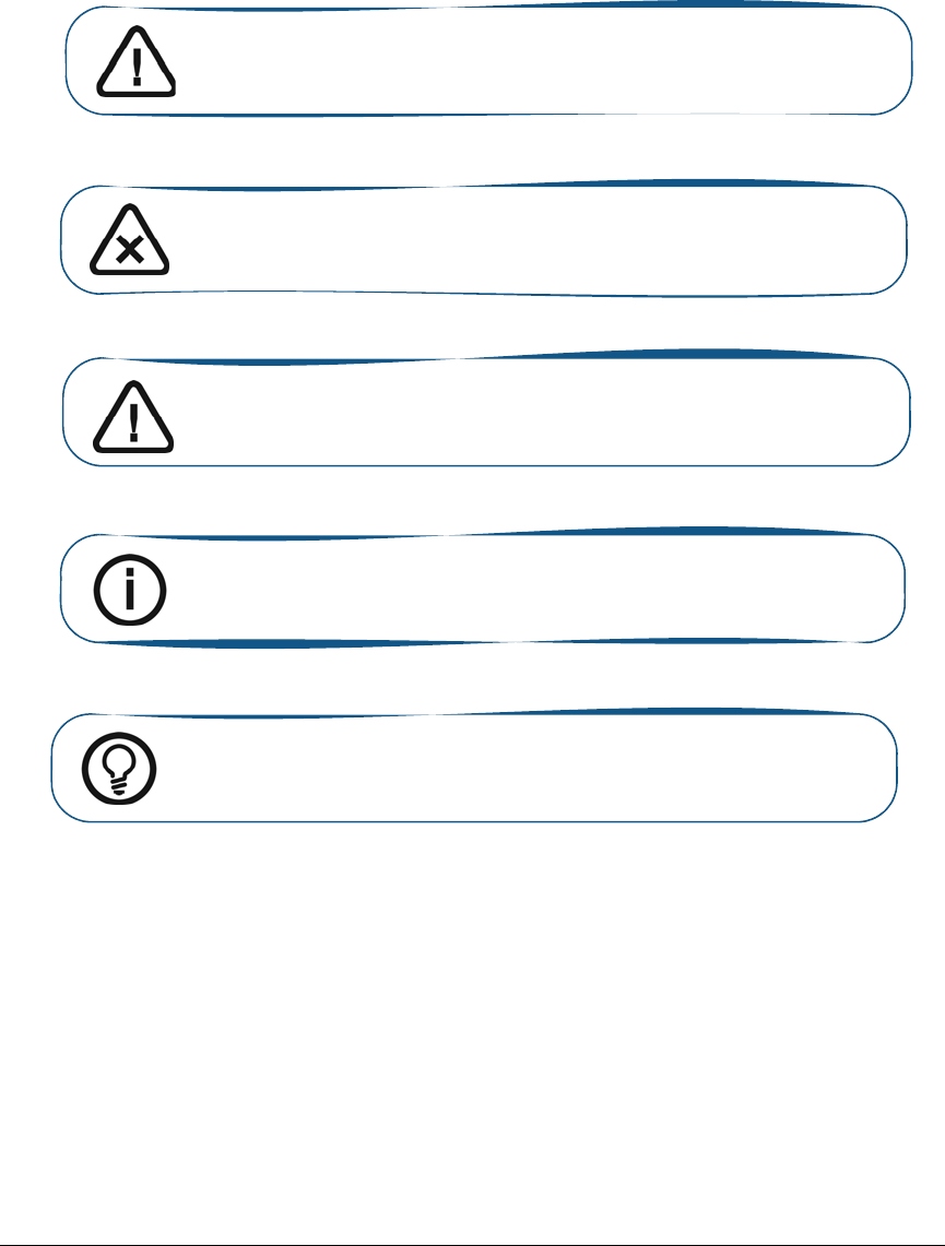
The following special messages emphasize information or indicate potential risk to personnel or
equipment:
WARNING: Warns you to avoid injury to yourself or others by following
the safety instructions precisely.
CAUTION: Alerts you to a condition that might cause serious damage.
Important: Alerts you to a condition that might cause problems.
Note: Emphasizes important information.
Tip: Provides extra information and hints.

2 Chapter 1 Conventions in This Guide
KODAK RVG 6500 System_User & Installation Guide (SM745)_Ed02 3
2 KODAK RVG 6500 With or Without IPS
System Packaging
KODAK RVG 6500 With or Without IPS System Description
The KODAK RVG 6500 with or withour IPS System is available in 2 configurations:
•The KODAK RVG 6500 System
OR
•The KODAK RVG 6500 Intelligent Positioning System (IPS) System
Packaging of KODAK RVG 6500 System
The KODAK RVG 6500 System packaging is composed of the following boxes:
•The RVG sensor box
•The WiFi access point box
•The positioning kit box
Packaging of KODAK RVG 6500 IPS System
The KODAK RVG 6500 IPS System packaging is composed of the following boxes:
•The RVG sensor box with IPS features
•The IPS aiming ring box
•The WiFi access point box
•The positioning kit box
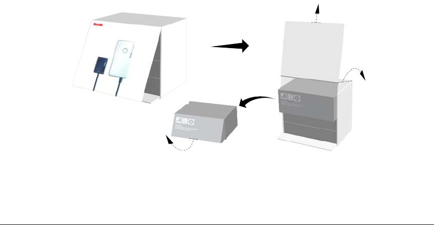
Opening the Boxes

4 Chapter 2 KODAK RVG 6500 With or Without IPS System Packaging
KODAK RVG 6500 System_User & Installation Guide (SM745)_Ed02 5
3 KODAK RVG 6500 Systems Overview
KODAK RVG 6500 Systems Overview
•The KODAK RVG 6500 System
OR
•The KODAK RVG 6500 Intelligent Positioning System (IPS) System
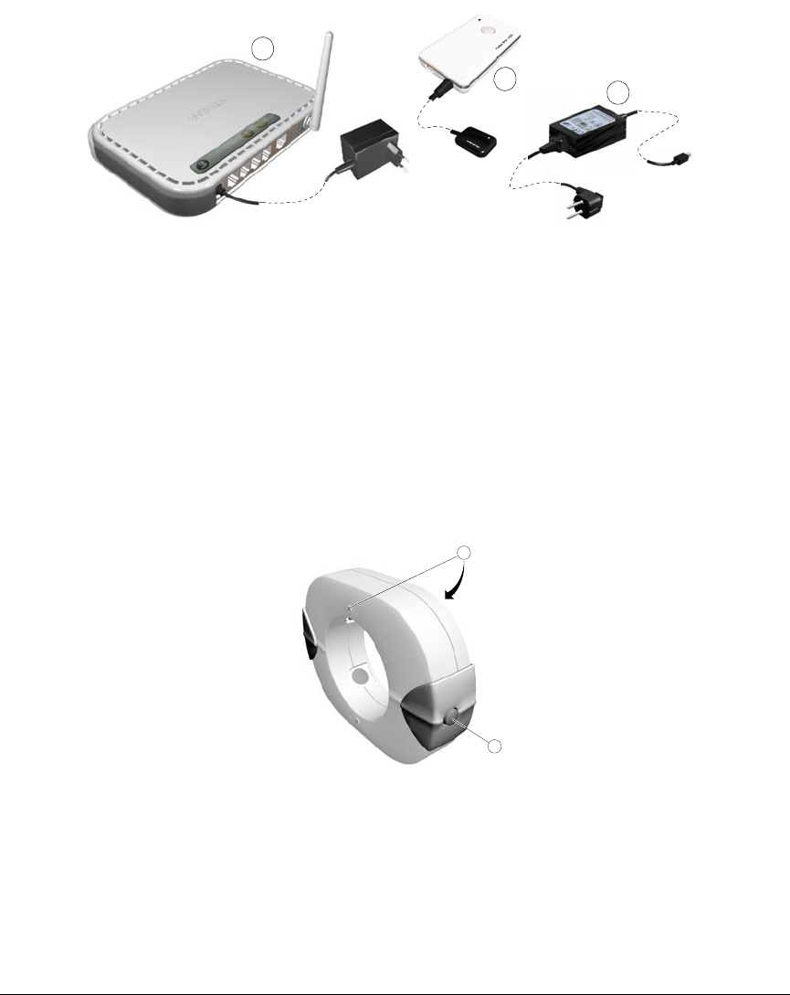
Figure 1 KODAK RVG 6500 System Components
The KODAK RVG 6500 IPS System is composed of all the KODAK RVG 6500 system components
and the IPS aiming ring. The IPS aiming ring enables you prior to acquisition to dynamically and visually
center and align the X-ray beam to the RVG sensor.
Figure 2 IPS Aiming Ring
1The sensor and the control box
2The WiFi access point
3The medical power supply for the RVG system
1ON/OFF button: A quick push on the ON/OFF button will light the front or back LED.
24 LEDS
13
2
2
1
6 Chapter 3 KODAK RVG 6500 Systems Overview
RVG Functional Components Overview
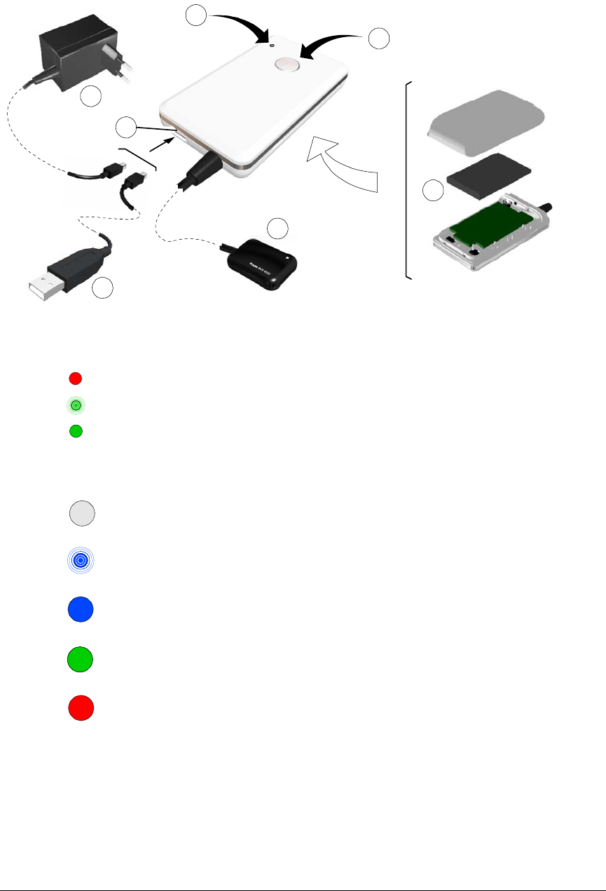
Figure 3 RVG Functional Components Overview
1 Battery status indicator LED:
Not charged
Charging (blinking)
Charged with charger connection
OFF Charged without charger connection
2 Sensor remote control button and the ON/OFF button:
OFF mode: Press 5 seconds to turn OFF
•Connecting to WiFi AP (blinking): Press 2 seconds to turn ON
•Transmitting acquired x-ray image (blinking)
•Connected to WiFi AP
•Standby mode
•Ready for acquisition
•RFID tag is identified
Error mode
3Sensor
4USB connector for battery charging
•(A) Medical charger
•(B) USB cable to charge with the computer
5Battery
3
1
2
4
A
B
5
KODAK RVG 6500 System_User & Installation Guide (SM745)_Ed02 7
WiFi Access Point Functional Components Overview
The WiFi access point is the wireless equivalent of the wired internal Local Area Network (LAN). The
WiFi access point provides connectivity between the computer and the RVG sensor(s) enabling you to
use the KODAK RVG 6500 within your practice area. See the manufacturer guide for any detailed
information on the WiFi access point.
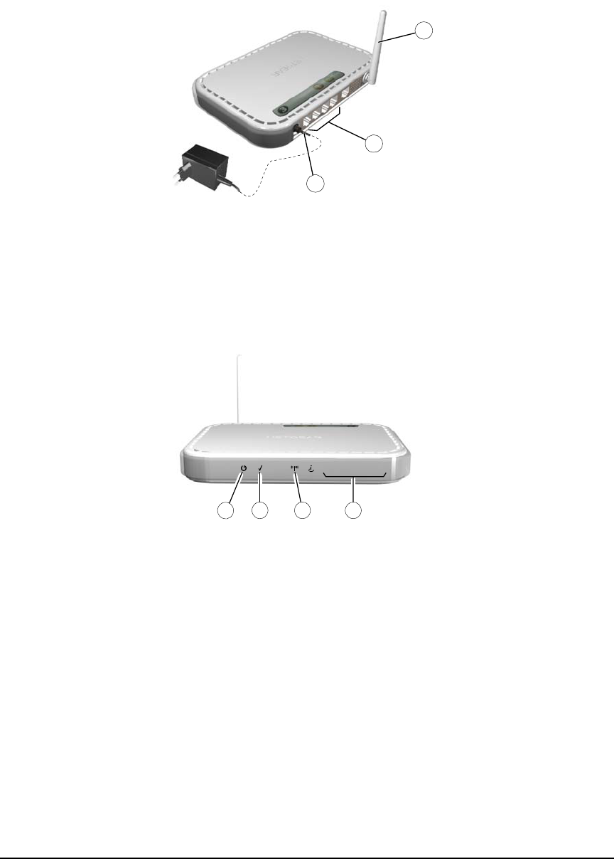
Figure 4 WiFi AP Back Panel Overview
Figure 5 WiFi Access Point Front Panel Overview
1Power adapter outlet.
24 local LAN 10/100 Mpbs Ethernet ports for connecting the WiFi AP to the local computers.
3Wireless antenna.
1Power indicator
2Tes t indicato r
3Wireless transmission indicator
4Local Area Network (LAN) indicator
1
2
3
NETGEAR
1234
12 43

8 Chapter 3 KODAK RVG 6500 Systems Overview
KODAK RVG 6500 System_User & Installation Guide (SM745)_Ed02 9
4 Imaging Software Overview
Computer System Requirements
Make sure that your computer is compatible with the computer system requirements detailed in
KODAK RVG 6500 System_Regulatory User Guide (SM737), Chapter 3.
General Software Overview
The KODAK RVG 6500 with or without IPS intraoral imaging system operates with the following
software:
•KODAK dental imaging software
•KODAK RVG 6500 systems software modules:
•RVG acquisition interface
•Intelligent Positioning System (IPS) interface (optional)
KODAK Dental Imaging Software
The KODAK dental imaging software is a user-friendly working interface that was designed and
developed specifically for radiological diagnosis. It is the common imaging platform for all our digital
systems for dentistry.
The KODAK dental imaging software has the following features:
•Patient record management using Patient Window features.
•Extraoral and intraoral image management using Imaging Window features.
Important: It is MANDATORY to check that the computer system
configuration is compatible with the computer system requirements
for the KODAK RVG 6500 with or without IPS system software.
Important: The screen with the proper technical display
characteristics for visualization of radiological images will avoid any
diagnostic error.
Note: For a complete information on how to use the KODAK Dental
Imaging Software, click ? in the menu bar to access the online help, or see
SM691 KODAK Dental Imaging Software Quick Start Guide.
10 Chapter 4 Imaging Software Overview
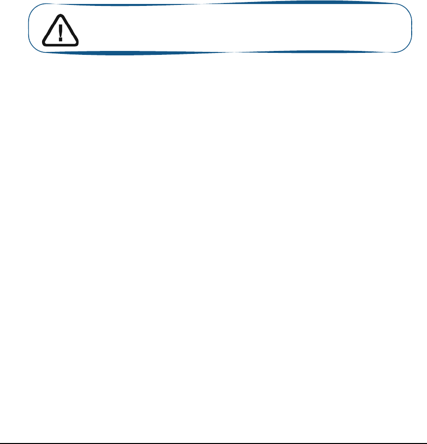
The RVG Acquisition Interface
The RVG Acquisition interface module is a user-friendly working interface that was designed and
developed specifically for the KODAK RVG 6500 with or without IPS intraoral imaging system.
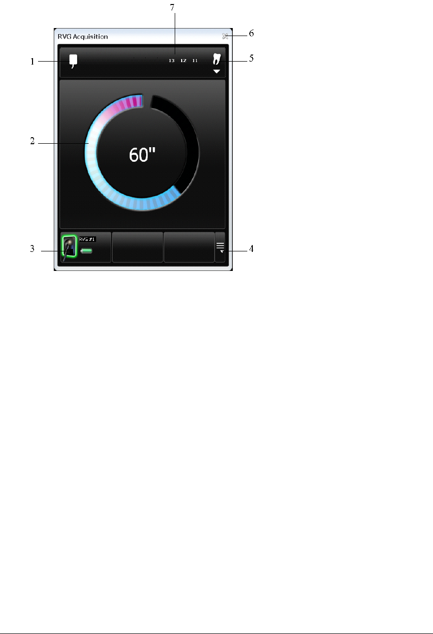
Figure 6 RVG Acquisition Main Interface
1 Sensor orientation: Pre-orients how the x-ray image is displayed in the Imaging Window.
2Preview screen:
•Indicates the 90 second activation time for acquisition.
•Displays the acquired x-ray image instantly after acquisition.
3Available sensor(s): Displays maximum 3 sensors with their name, sensor status and battery
status.
•Blue: Sensor on standby
•Green: Sensor ready for acquisition
•Red: Error mode
4 Sensor list: Accesses the list of the sensors (see Figure 6).
5 Dental arch interface: Accesses the dental arch interface for tooth selection (see figure 7).
6 Exit button: Exits the Acquisition Interface.
7 Tooth display: Displays the selected tooth number.
KODAK RVG 6500 System_User & Installation Guide (SM745)_Ed02 11
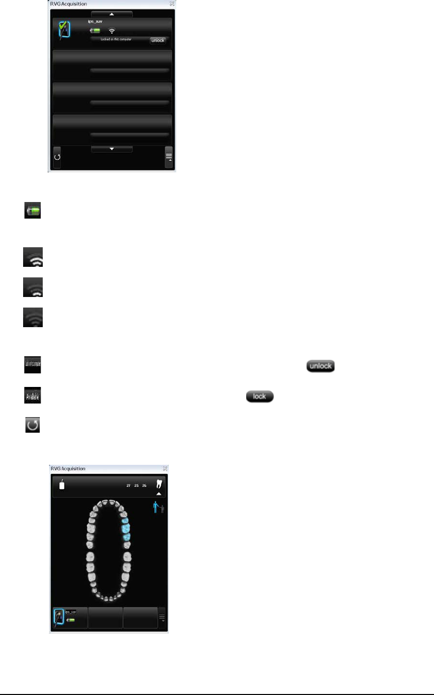
Figure 7 List of Available Sensors
Figure 8 Dental Arch for Tooth Selection
To select the desired tooth or teeth for acquisition, click on the tooth. The tooth number for acquisition
is displayed as shown in the Figure 5.
The sensor name and battery status:
Battery status.
The WiFi status:
Wifi transmission is available.
Wifi transmission is available but not good.
WiFi transmission is not available.
The Sensor availability:
Sensor is connected to your computer and ready for use. Click to disconnect.
Sensor is not connected to your computer. Click to connect.
Refresh button refreshes the list of sensors visible in the computer.
12 Chapter 4 Imaging Software Overview
The IPS Aiming Ring Interface Overview
The IPS aiming ring interface is a user-friendly working interfaces that was designed and developed
specifically for the KODAK RVG 6500 IPS System intraoral imaging system. It enables you prior to
acquisition to dynamically and visually center the x-ray beam to the RVG sensor using the centering
indicator.
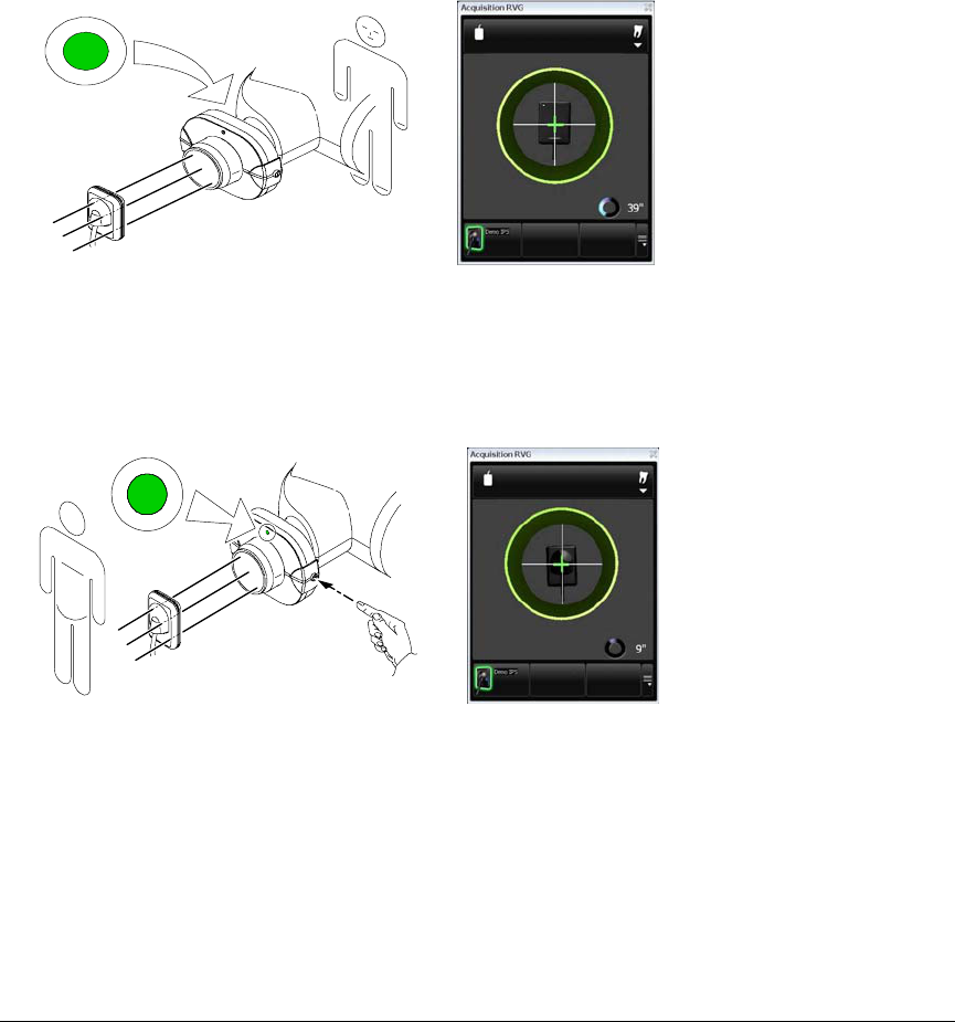
IPS Aiming Ring Interface and RVG Sensor Display
The IPS aiming ring interface displays the RVG sensor according to where you are positioned, that is,
in front or behind the aiming ring. The operator where positioned (in front or behind) must always see
the LED (front or back) of the aiming ring ON. A quick push on the ON/OFF button will light the front
or the back LED.
•Operator is positioned
behind the aiming ring.
•Back LED is ON.
•Sensor active side is
displayed.
•Operator is positioned in
front of the aiming ring.
•Front LED is ON.
•Sensor back side is
displayed.
KODAK RVG 6500 System_User & Installation Guide (SM745)_Ed02 13
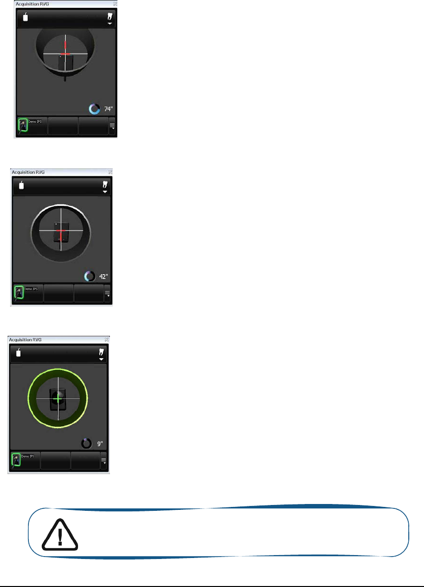
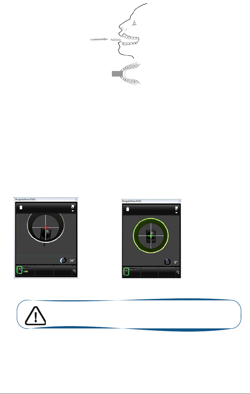
IPS Aiming Ring Interface and RVG Sensor Centering
The IPS aiming ring interface enables you to correctly position the X-ray generator to the RVG sensor.
The IPS interface enables you to manage the X-ray centering and the proper paralleling technique
achievement.
Sensor Display
•Sensor is not centered.
•Centering indicators are
red.
Result
•Sensor active surface not fully
exposed to X-ray.
•Image will have a cone cut.
•Parallel technique not achieved.
•Image distortion.
Sensor Display
•Sensor is centered.
•Centering indicators are
red.
Result
•Sensor active surface is fully exposed
to X-ray;
•Image will have no cone cut.
•Parallel technique not achieved.
•Minimized risk of magnification and
distortion.
Sensor Display
•Sensor is centered.
•Centering indicators are
green.
Result
•Sensor active surface is fully exposed
to X-ray;
•Image will have no cone cut.
•Parallel technique achieved*.
•Minimized risk of magnification and
distortion.
Important: *The paralleling technique is achieved when the digital sensor
plane is placed parallel to the real axis of the tooth in the patient’s mouth.
This correct positioning is under the operator’s responsibility.

14 Chapter 4 Imaging Software Overview
KODAK RVG 6500 System_User & Installation Guide (SM745)_Ed02 15
5 Setting Up the KODAK RVG 6500
Systems
KODAK RVG 6500 Systems Configuration Options
Option 1: Single RVG Sensor / Single PC / Single Access Point Configuration
•Single WiFi AP wired setup (see: For a first system configuration “Installing the KODAK
Dental Imaging Software” . For reconfiguration “Starting the Configuration Setup” ).
•Direct RVG sensor connection to the PC (see “Locking a Single RVG Sensor to the
Computer.” ).
Option 2: Single RVG Sensor / Multi-PC / Single Access Point Configuration
•Single WiFi AP wireless setup (see: For a first system configuration “Installing the
KODAK Dental Imaging Software” . For reconfiguration “Starting the Configuration
Setup” ).
•RFID RVG sensor connection to multi-PCs (see “Connecting an RVG RFID Sensor to
the Computer” ). This is a recommended configuration.
Important: Your computer must have an Ethernet board and be WiFi
equipped before installing the KODAK RVG 6500 systems.
NETGEAR
1234
NETGEAR 1234
max. 10m
max. 10m max. 10m
max. 10m
16 Chapter 5 Setting Up the KODAK RVG 6500 Systems
•OR
•Manual RVG sensor connection to multi-PCs (see “Locking a Single RVG Sensor to the
Computer.” ). This is a possible configuration but not recommended.
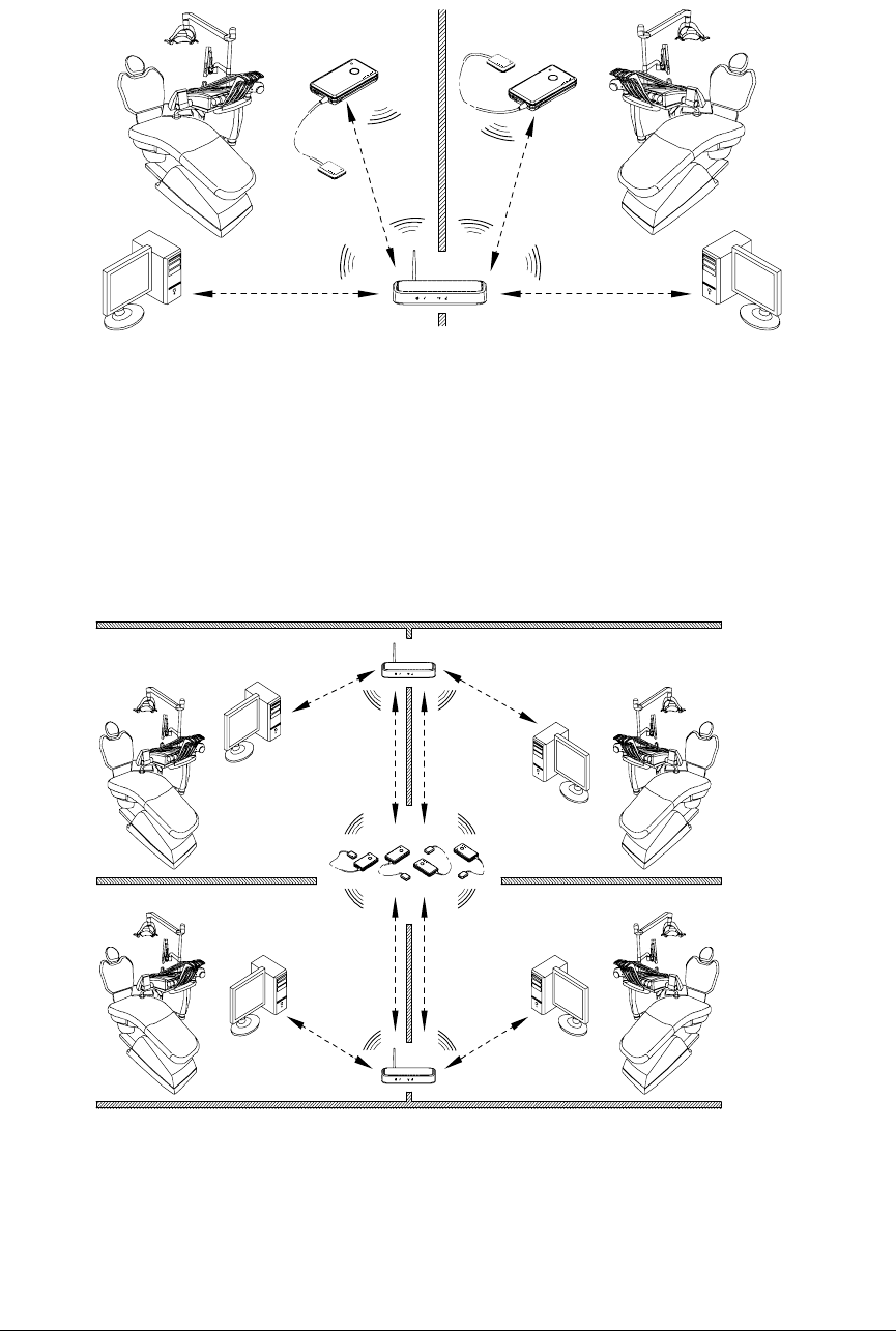
Option 3: Multi-RVG Sensor / Multi-PC / Single Access Point Configuration
•Single WiFi AP wireless setup (see: For a first system configuration “Installing the
KODAK Dental Imaging Software” . For reconfiguration “Starting the Configuration
Setup” ).
•RFID RVG sensor connection to multi-PCs (see “Connecting an RVG RFID Sensor to
the Computer” ). This is a recommended configuration.
•OR
•Manual RVG sensor connection to multi-PCs (see “Locking Several Shared RVG
Sensors to the Computer.” ). This is a possible configuration but not recommended.
Option 4: Multi-RVG Sensor / Multi-PC / Multi-Access Point Configuration
•Multi-WiFi AP wireless setups (see: For a first system configuration “Installing the
KODAK Dental Imaging Software” . For reconfiguration “Starting the Configuration
Setup” ).
•Mandatory, RFID RVG sensor connection to multi-PCs (see. “Connecting an RVG RFID
Sensor to the Computer” ).
NETGEAR
1234
max. 10m
max. 10m
max. 10m
max. 10m
NETGEAR
1234
NETGEAR
1234
max. 10m
max. 10m max. 10m
max. 10m
max. 10m
max. 10m max. 10m
max. 10m
KODAK RVG 6500 System_User & Installation Guide (SM745)_Ed02 17
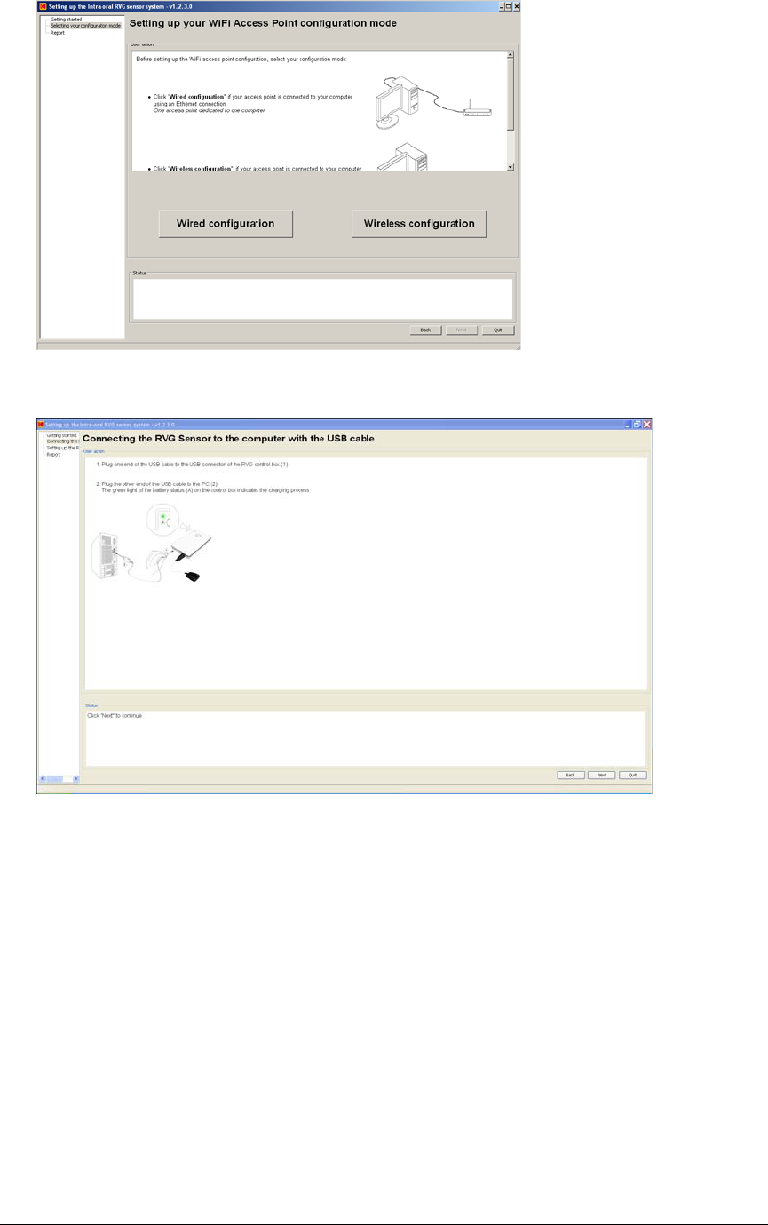
WiFi Access Point Setup Configurations
There are 2 WiFi access point setup configuration options:
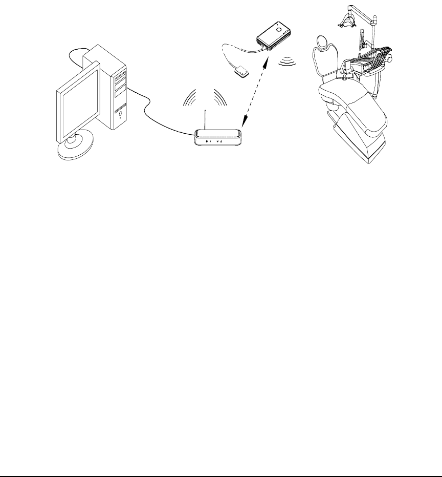
•The wired WiFi access point setup configuration (preferably “Option 1: Single RVG Sensor /
Single PC / Single Access Point Configuration” )
•The wireless WiFi access point setup configuration
You must decide the KODAK RVG 6500 system configuration option before starting the WiFi setup.
Once you have decided you will be guided by the setup software (see: For a first system configuration
“Installing the KODAK Dental Imaging Software” . For reconfiguration “Starting the Configuration
Setup” ).
WiFi Access Point Wired Configuration Setup
You can choose to have a wired WiFi access point configuration. In this configuration setup, the WiFi
access point is connected to a single computer through an Ethernet cable. Several sensors can be
connected to the same access point and computer.
The transmission range between the WiFi access point and the RVG sensor is up to 10 meters.
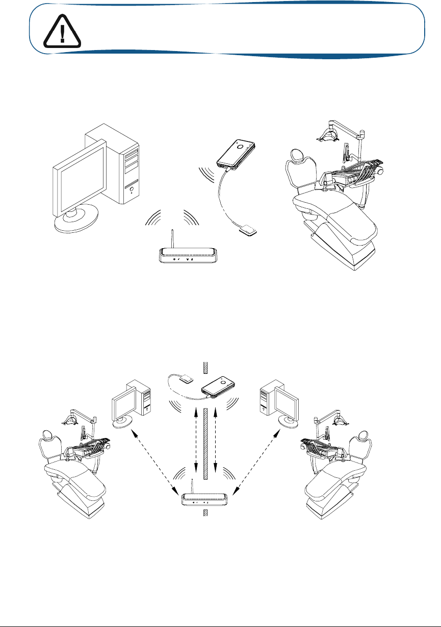
WiFi Access Point Wireless Configuring Setup
You can chose to have a wireless WiFi access point configuration. In this configuration setup, the
computer is connected to the WiFi access point through a router, that is, through a dongle or a PCI
card. In this configuration, several sensors can be connected to the same access point and shared
between several computers and chairs.
For optimal WiFi access point wireless setup, follow these setup recommendations:
•Place the WiFi access point in a visible and high location (not on the floor).
•Place the WiFi access point in a central location for a multiple access point transmission.
•Avoid any barriers along the line of transmission, for example, armored wall and door, cabinets,
effronteries and metal file cabinets.
•Install the WiFi access point at 1 meter distance from other appliances transmitting the same
frequency range.
•Install the WiFi access point away from electrical equipment that also generates interferences.
In this configuration, the transmission range between WiFi access point and:
•The RVG sensor is up to 10 meters.
•The computer is up to 10 meters.
NETGEAR
1234
max. 10m
18 Chapter 5 Setting Up the KODAK RVG 6500 Systems
Installing the KODAK Dental Imaging Software
Before installing the KODAK Dental Imaging Software, check that:
•The computer has all the PC system requirements
•You have the software DVD as of version 6.12 or higher
To install the KODAK Dental Imaging Software, follow these steps:
1Insert the software DVD in the DVD-ROM drive of the computer.
Wait for the installation program to start. If the program does not start automatically, click Start >
Run and enter D:\setup.exe if D is the letter for the DVD-ROM drive, or the letter of the relevant
drive on the computer.
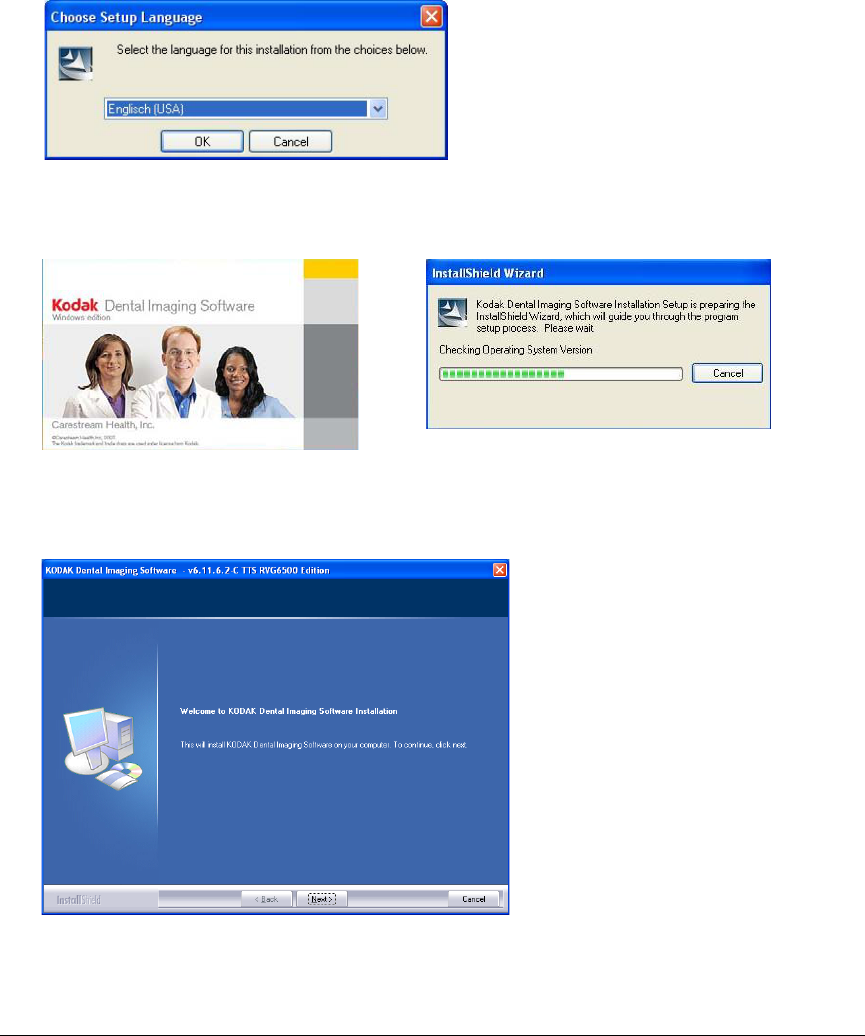
2The Choose Setup Language dialog box is displayed. Select the installation language and click
OK.
3The Kodak Dental Imaging Software welcome page and the InstallShield wizard are displayed.
4The Welcome to KODAK Dental Imaging Software Installation dialog box is displayed. Click
Next to launch the installation.
KODAK RVG 6500 System_User & Installation Guide (SM745)_Ed02 19
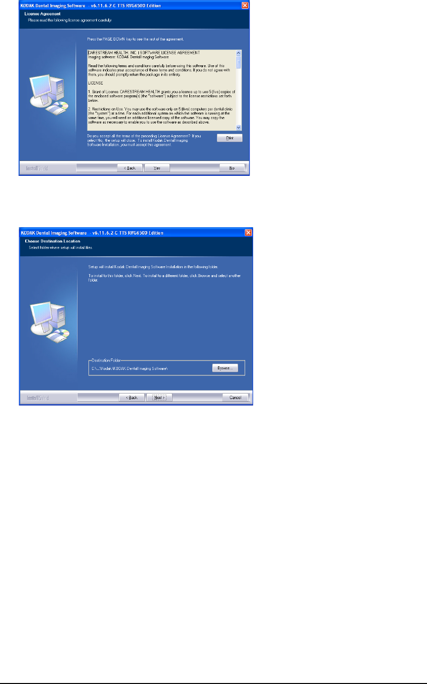
5The License Agreement dialog box is displayed. Accept and click Yes .
6The Choose Destination Location dialog box is displayed. Click Next if you accept the default
destination folder (c:\program files\Kodak\Kodak Dental Imaging Software) or browse to choose
another destination folder.
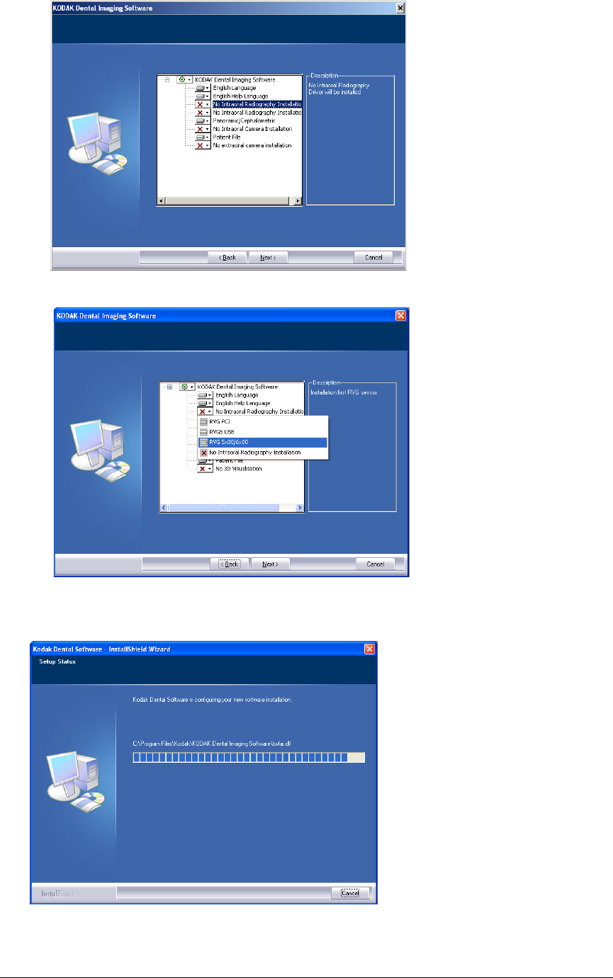
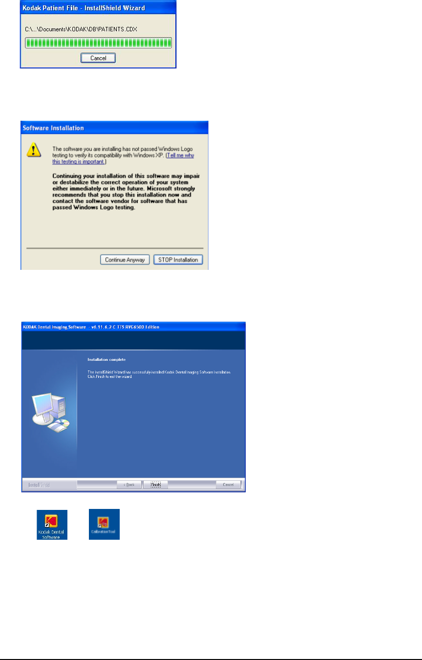
7The KODAK Dental Imaging Software dialog box is displayed. The Patient file is selected by
default but you must select the device.
8To select the desired device, do the following:
20 Chapter 5 Setting Up the KODAK RVG 6500 Systems
〈Click on the drop-down list of No Intraoral Radiography Installation.
〈Select RVG 5x00/6x00.
〈Click Next to begin the installation.
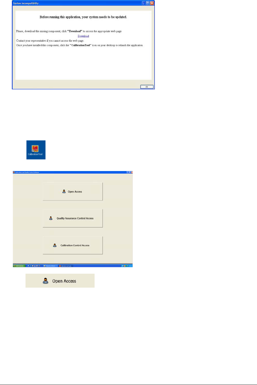
The InstallShield Wizard is displayed. Let the installation process run automatically.
KODAK RVG 6500 System_User & Installation Guide (SM745)_Ed02 21
The Kodak Patient file - InstallShield Wizard is displayed while the patient files are installed on
the hard drive.
The Software Installation dialog box is displayed while the installation process continues. Click
Continue Anyway until the dialog box disappears.
9The Installation Complete dialog box is displayed when the installation is finished. Click Finish.
The and are installed on your desktop.
If your computer operating system is not compatible with the system requirements follow
the instructions below, otherwise go to step 13.
22 Chapter 5 Setting Up the KODAK RVG 6500 Systems
If your PC operating system is not compatible with the system requirements
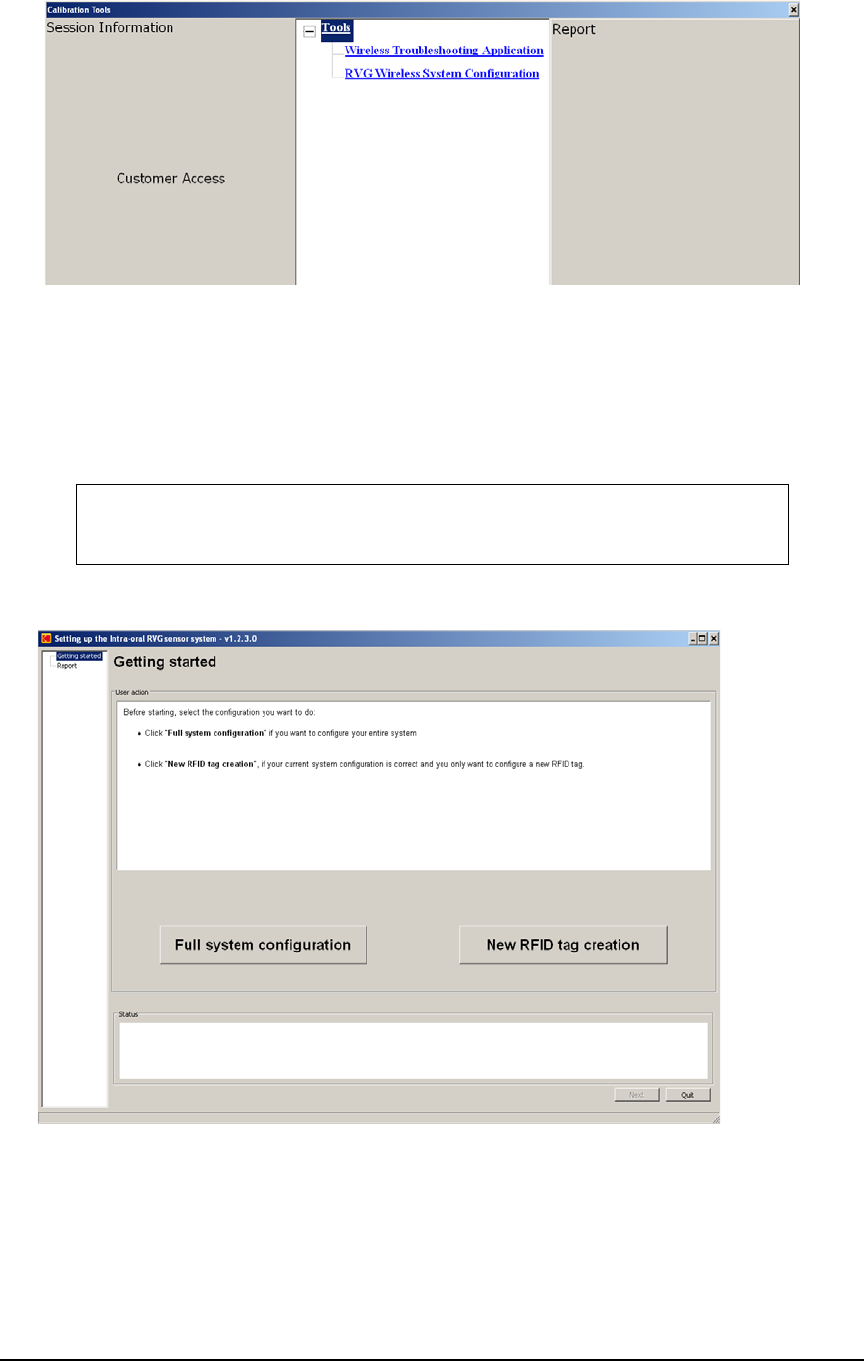
If your PC operating system is not compatible with the system requirements, the System
incompatibility dialog box is displayed. Click Download, your application will close automatically.
Follow the on-screen instructions to install the required “Windows Wireless component”. Reboot
your PC when the installation is completed.
10 Click on your desktop. The Calibration and Quality Control Software window is
displayed.
11 Click . The Calibration Tools window is displayed.
KODAK RVG 6500 System_User & Installation Guide (SM745)_Ed02 23
12 In the central pane, click RVG Wireless System Configuration, to access the “Setting Up the
WiFi AP” window (see and follow step 10).
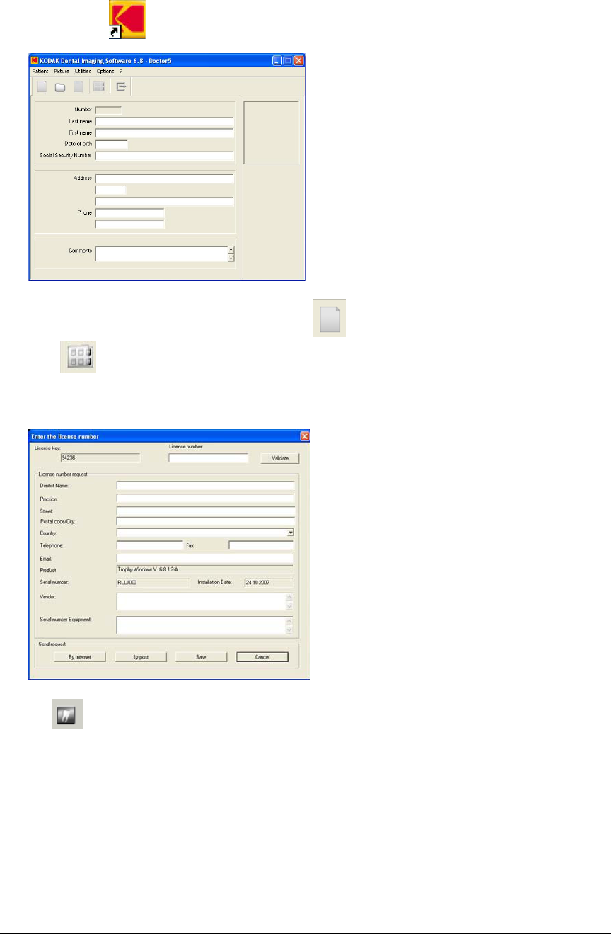
Starting the Configuration Setup
13 Before the setting up of the KODAK RVG 6500 System procedures, have with you the:
14 The “Setting Up the Intra-oral RVG Sensor system” window is automatically displayed.
You have 2 setup options:
•Full system configuration: When you want to configure the entire system.
•New RFID tag creation: When your current system configuration is correct and you only want
to configure a new RFID tag.
SSID Password
RVG8_NETWORK 7794AA6500EC239BFF4554DD80
24 Chapter 5 Setting Up the KODAK RVG 6500 Systems
15 Click Full system configuration and follow the on-screen instructions to setup the RVG system
Click New RFID tag creation and follow the on-screen instructions to configure a new RFID tag.
Once you have finished setting up the RVG system, you must register the KDIS Licence.
KODAK RVG 6500 System_User & Installation Guide (SM745)_Ed02 25
Registering the KDIS Licence
To register the KDIS licence, follow these steps:
1Double-click to open the Patient Window.
2Create a patient record. From the toolbar, click and enter the required patient information.
Click to access the Imaging Window.
3The Enter the licence number dialog box is displayed. Enter the licence number and click
Validate if you have the licence number or click Cancel to continue.
The icon appears on the toolbar of the Imaging Window.
For the RVG Mobile Application installation (optional), see Chapter 7.
26 Chapter 5 Setting Up the KODAK RVG 6500 Systems
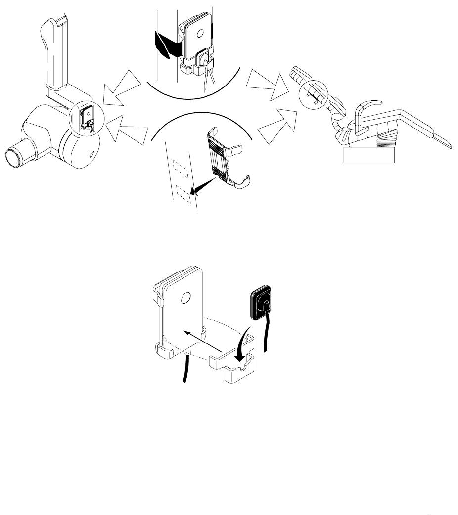
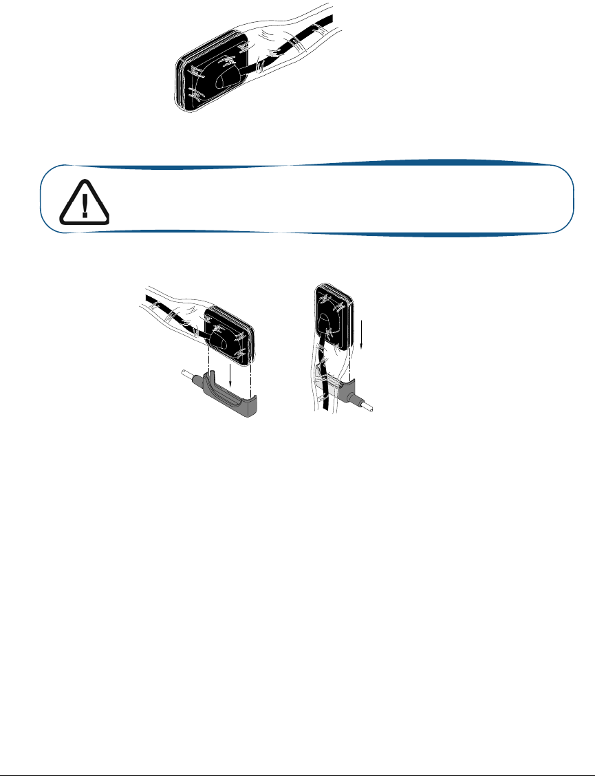
Mounting the RVG Holders
The RVG sensor and control box holders enable you to have them at reach to optimize your workflow.
You need to install the RVG sensor and control box holders where it best suits your workflow, the X-ray
generator arm, the chair, etc....
To mount the RVG sensor and control box holders, follow these steps:
1Attach the RVG control box holder with the double-face adhesive or the Velco strap supplied on
the side of the X-ray generator arm.
You can also attach the RVG control box holder with the double-face adhesive or the Velco strap
to the chair or any other flat surface close to the patient’s chair.
The RVG control box holder can also be mounted on the wall with screws (not supplied).
2Clip the RVG sensor holder on the control box. Insert the RVG sensor in its holder.
KODAK RVG 6500 System_User & Installation Guide (SM745)_Ed02 27
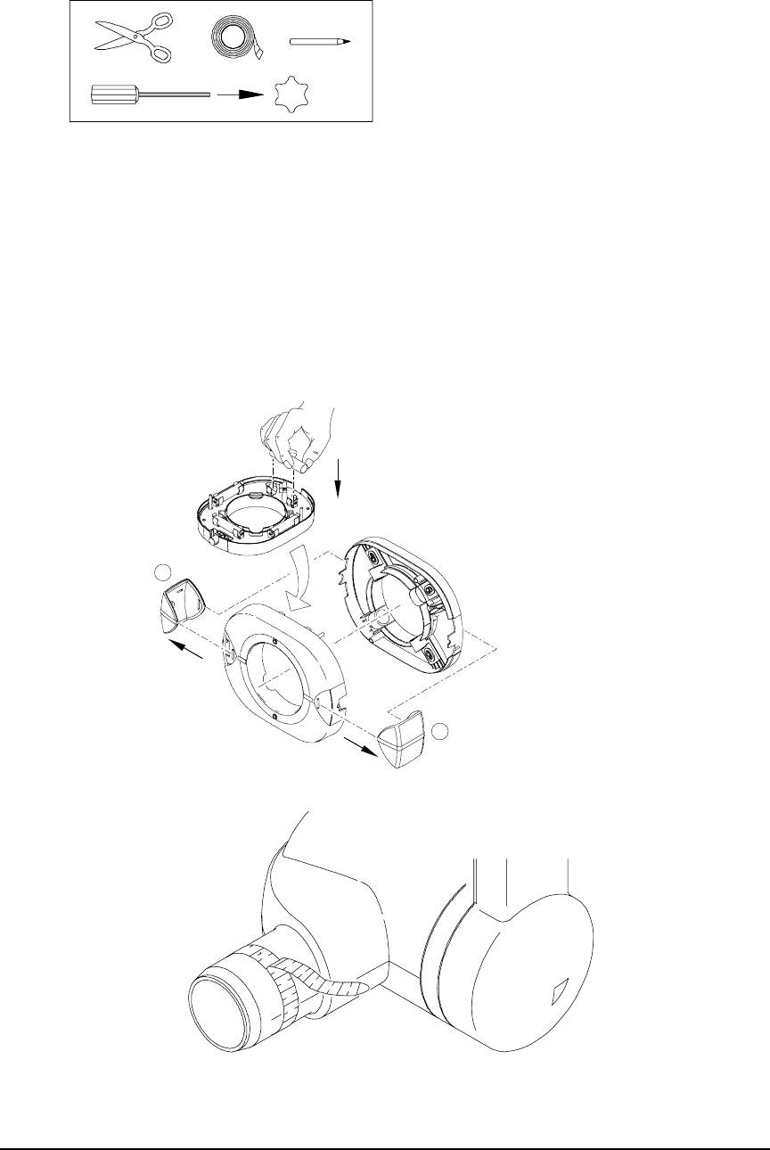
Mounting the IPS Aiming Ring on the X-Ray Generator
Before mounting the IPS aiming ring, make sure that:
•You have the necessary tools:
•You have cleaned the X-ray generator tube head with disposable cleaning wipes.
•You have asked the practitioner his preference for the position of the aiming ring on the X-ray
tube head, with the ON/OFF button on the left or right side of the X-ray tube head.
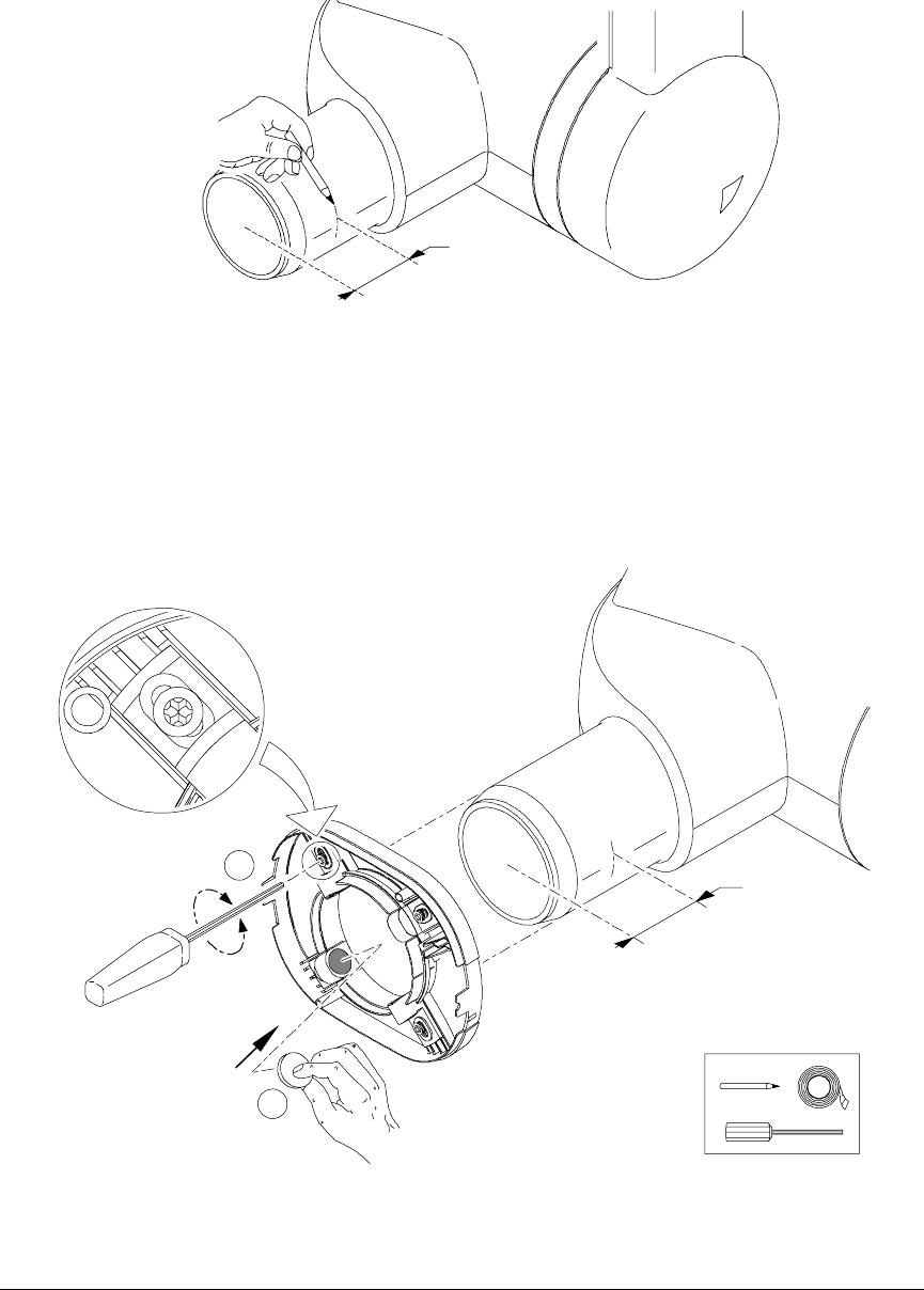
To mount the IPS aiming ring on the X-ray generator tube head, follow these steps:
1Remove the attachment brackets (A).
2Remove the back cover.
3Insert the 4 batteries on the board respecting the polarities.
4Measure the X-ray tube head diameter to select the appropriate aiming ring holding brackets.
15 mm
x4
A
A
28 Chapter 5 Setting Up the KODAK RVG 6500 Systems
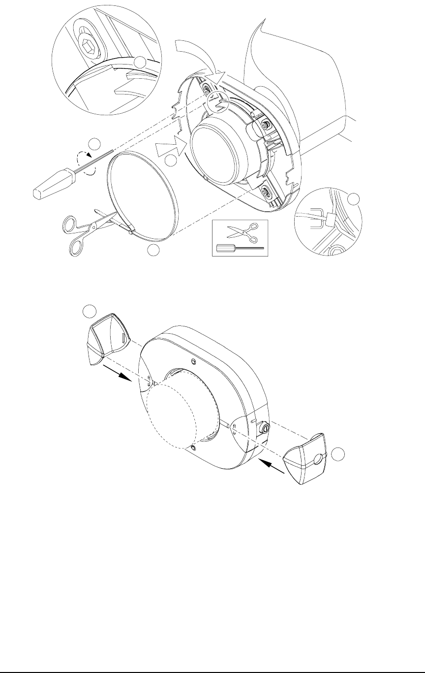
5Select the appropriate aiming ring holding brackets (B):
•For a cone shape x-ray tube head (HY415).
•For a cylindrical shape x-ray tube head with diameters from 55.5 mm to 65 mm (HY414).
•For a cylindrical shape x-ray tube head with diameters from 64 mm to 70.1 mm (HY413)
mounted on the ring.
6Measure from the opening of the x-ray tube head 30mm. Mark the 30mm with a pencil on both
sides of the x-ray tube head.
7On the back cover, position the appropriate holding brackets (B) to adapt to the x-ray tube head
diameter. Do not tighten the screws.
8Stick the stickers on the back cover in the appropriate locations (C). Remove the protection on the
stickers.
9Using the 30mm marks, position the back cover on the x-ray tube head. Tighten the 4 screws.
30 mm
x4
B
x4
C
30 mm
KODAK RVG 6500 System_User & Installation Guide (SM745)_Ed02 29
10 Place the cable tie (A) around the holding brackets (B), make a knot and place it in the cable tie
holder (C). Pull to tighten and cut what exceeds the knot. Retighten the screws, if needed.
11 Position correctly the front cover with the board making sure that the ON/OFF button is on the
appropriate place.
12 Position correctly the attachment brackets (A).
13 Press quickly the ON/OFF button to turn ON the IPS device and check that the front upper LED is
lit.
Press quickly the ON/OFF button to turn ON the back upper LED to check that it is lit.
14 Press and hold the ON/OFF button until all the LEDs are ON, then let go the ON/OFF button to
turn OFF the IPS.
The IPS aiming ring installation is finished.
A
A
x4
B
C
C
A
A

30 Chapter 5 Setting Up the KODAK RVG 6500 Systems
KODAK RVG 6500 System_User & Installation Guide (SM745)_Ed02 31
6 Acquiring an Image With RFID
Connecting an RVG Sensor to the Computer
You need to connect the selected RVG sensor to the computer where the acquired image must
appear.
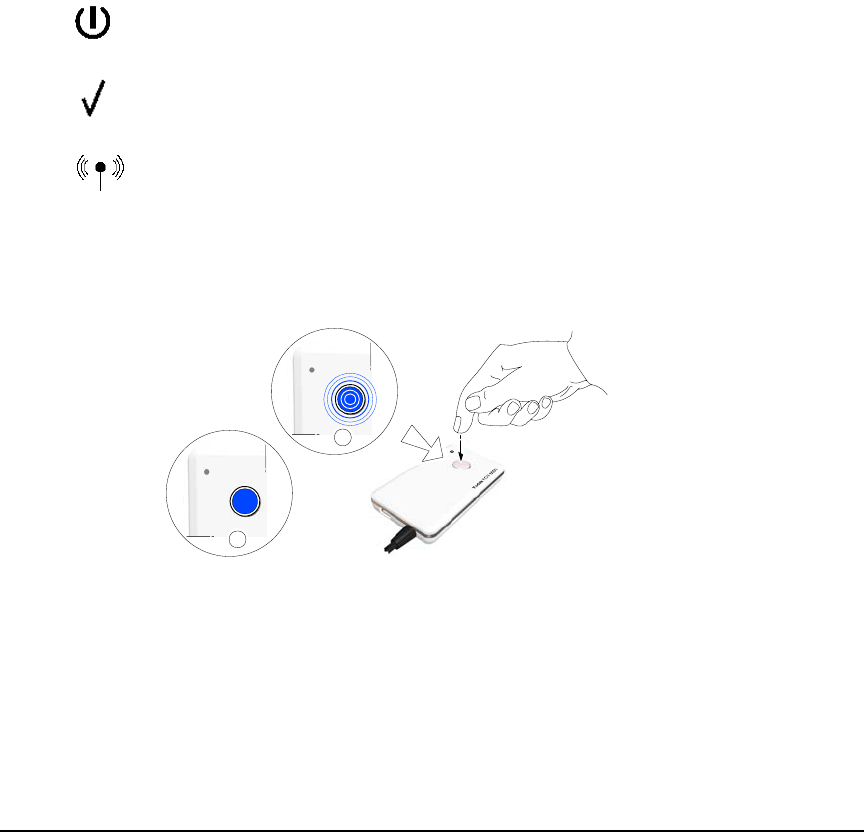
To connect an RVG sensor to your computer, follow these steps:
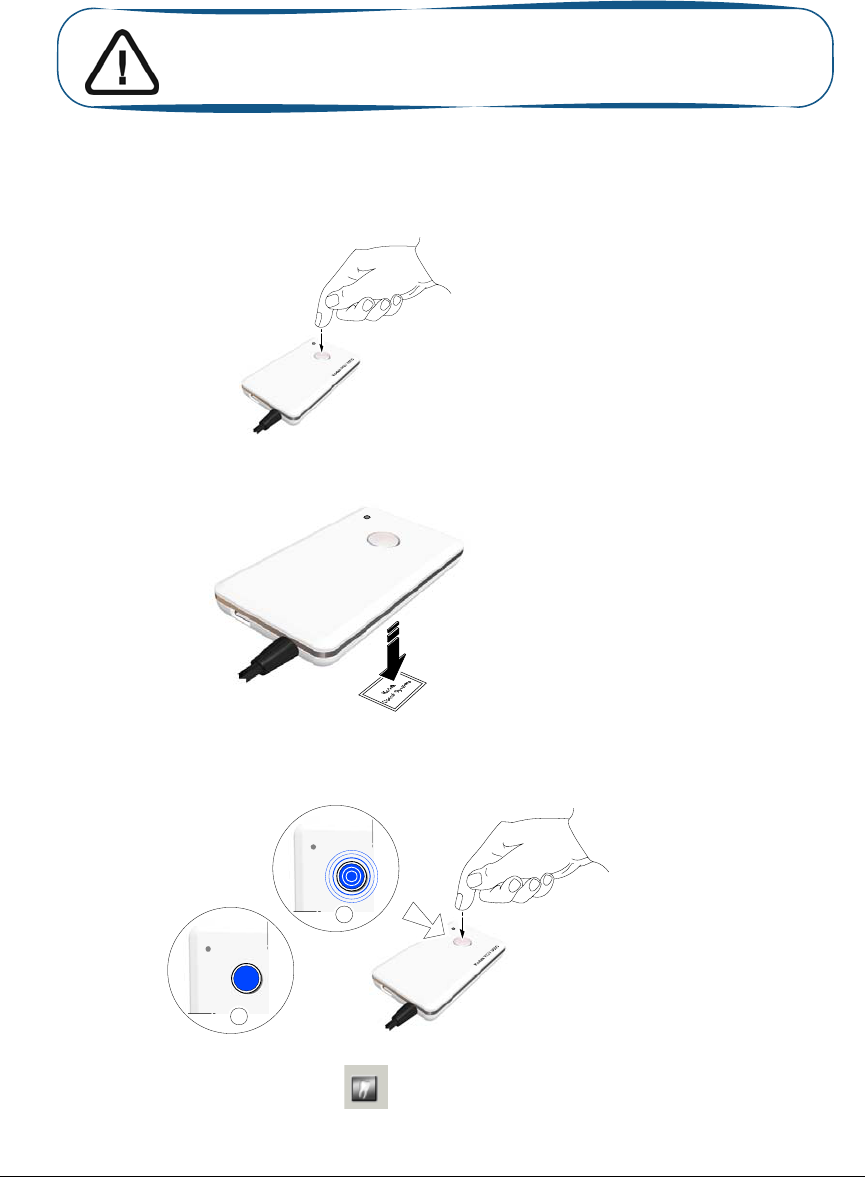
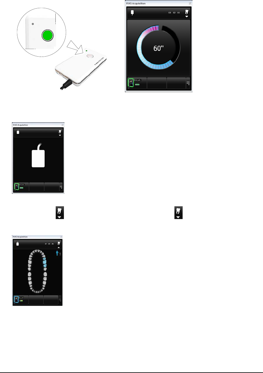
1Press the remote control button of the RVG control box to turn ON the device.
2Place the RVG sensor on the RFID tag. .
3Press again the remote control button and wait for the blinking blue light (A) to become solid blue.
(B) The sensor is connected to the WiFi access point and connected to the computer
4Access the Imaging Window. Click to access the RVG Acquisition interface.
Important: You can use the RVG sensor to acquire an image while
charging ONLY with the medical charger.
A
B
32 Chapter 6 Acquiring an Image With RFID
You can also access the RVG Acquisition interface, doing the following:
•Press the remote control button of the selected RVG control box, or
•Press F2 on the computer key board.
Acquiring an Image with the RVG Sensor
To acquire an image with the RVG sensor, follow the instructions in the presented order.
Preparing the RVG Sensor
To prepare the selected RVG sensor, follow these steps:
1Select an appropriate positioner for the region of interest and the sensor size.
2Cover with a disposable hygienic sleeves specifically designed for each sensor size.
.
3Place the protected RVG sensor in the sensor positioner’s biteblock.
Important: To prevent cross-contamination, use a new hygienic
barrier for each new patient.

KODAK RVG 6500 System_User & Installation Guide (SM745)_Ed02 33
Preparing the X-Ray Generator
To prepare the x-ray generator, follow these steps:
1Press the remote control button of the selected RVG control box to access the RVG Acquisition
interface.
(Optional) Press on the remote control button several times to pre-orient the sensor orientation.
The acquired image is displayed with the last selected orientation on the Imaging Window.
(Optional) Click To select the tooth or teeth number. Click to return to the RVG
Acquisition interface. The selected tooth number is displayed on the RVG Acquisition interface.
2Select the x-ray timing according to the region of interest and the patient type (follow the user
instructions of your x-ray generator).
34 Chapter 6 Acquiring an Image With RFID
3Insert the sensor holding it horizontally in the patient’s mouth. Positioning in the patient’s mouth
depends on the region of interest.
4Approach the x-ray generator tube head to the patient.
(Optional) If you are using the IPS aiming ring system, press the ON button. If you are in front
of the aiming ring, make sure that the front LED is ON. If you are positioned in the back of the
aiming ring, a quick press on the ON/OFF button will turn on the LED on the back.
5Align the x-ray tube head with the patient’s tooth and the sensor and make sure that the tube head
is not shacking.
(Optional) If you are using the IPS aiming ring system, position the X-ray generator parallel to
the active surface of the RVG sensor. When the RVG sensor is correctly centered in the ring the
centring indicator becomes a green cross.
Important: The IPS aiming ring turns off after 90 seconds.

KODAK RVG 6500 System_User & Installation Guide (SM745)_Ed02 35
Launching the X-Ray
To launch the x-ray, follow these steps:
1Ask the patient to remain still.
2Position yourself either 2 meters behind the x-ray generator or outside the door.
3Keep visual contact with the patient during the x-ray.
4Trigger the x-ray with the remote control of the x-ray generator.
The image appears in the preview screen of the RVG Acquisition interface. The light on the remote
control button blinks blue indicating the image transmission.
When the acquisition ends, the RVG Acquisition interface disappears and the acquired image is
displayed in the Imaging Window. The light on the remote control button becomes solid blue.
5Check the image quality. If not satisfactory, redo the x-ray.
6If satisfactory, remove the generator tube head.
7Remove the RVG sensor from the patient’s mouth. Remove the hygienic sensor protection.
Important: DO NOT pull the sensor by its cable when you remove
the hygienic protection.

36 Chapter 6 Acquiring an Image With RFID
KODAK RVG 6500 System_User & Installation Guide (SM745)_Ed02 37
7 Acquiring an Image Without RFID
Locking the RVG Sensor to the Computer
You need to lock the RVG sensor to the computer where the acquired image must appear.
Locking a Single RVG Sensor to the Computer
If you have a single RVG sensor, you need to lock it only once to the computer where the acquired
image must appear.
To Lock the RVG sensor to your computer, follow these steps:
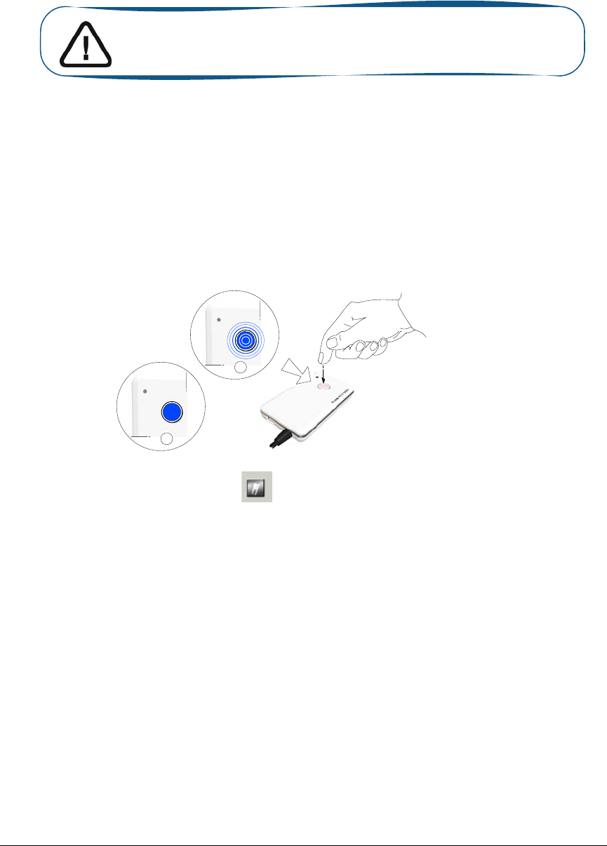
1Press the remote control button of the RVG control box to turn ON the device. The blinking blue
light indicates the sensor attempt to connect to the WiFi access point. Wait for the blinking blue
light (A) to become solid blue. (B) The sensor is connected to the WiFi access point.
2Access the Imaging Window. Click to access the RVG Acquisition interface.
You can also access the RVG Acquisition interface, doing the following:
•Press the remote control button of the selected RVG control box, or
•Press F2 on the computer key board.
Important: You can use the RVG sensor to acquire an image while
charging ONLY with the medical charger.
A
B
38 Chapter 7 Acquiring an Image Without RFID
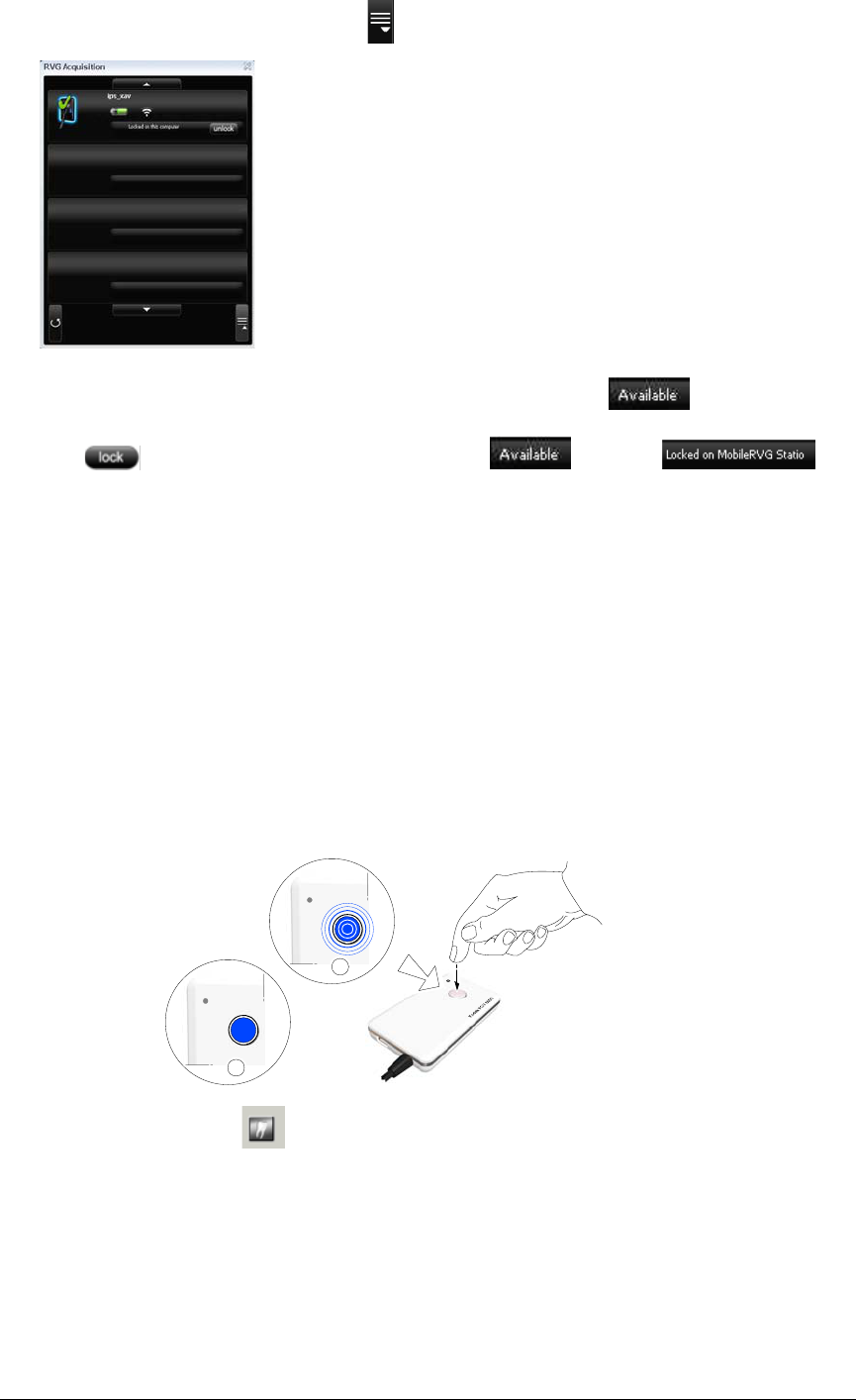
3In the RVG Acquisition interface, click to access the RVG sensor list.
4Find the RVG sensor in the sensor list. The sensor is identified with .
5Click to connect the sensor to your computer, becomes .
Locking Several Shared RVG Sensors to the Computer
If you have several shared RVG sensors, you need to lock the selected RVG sensor to the computer
where the acquired image must appear.
To lock the selected RVG sensor to your computer, follow these steps:
1Press the remote control button of the RVG control box to turn ON the device. The blinking blue
light indicates the sensor attempt to connect to the WiFi access point. Wait for the blinking blue
light (A) to become solid blue (B). The sensor is connected to the WiFi access point. Access the
Imaging Window. Click to access the RVG Acquisition interface.
A
B
KODAK RVG 6500 System_User & Installation Guide (SM745)_Ed02 39
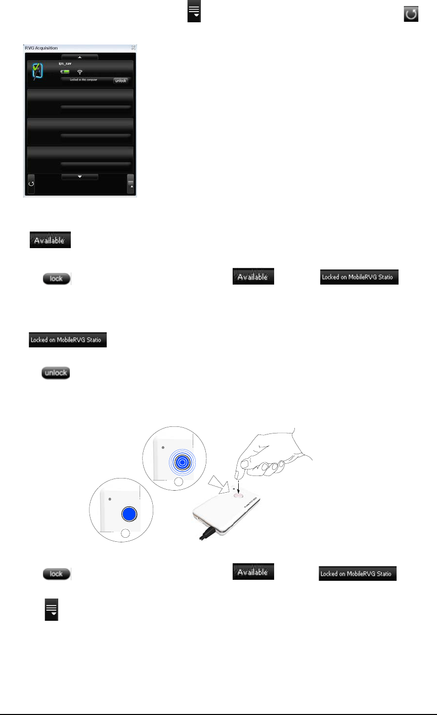
2In the RVG Acquisition interface, click to access the RVG sensor list. If needed, click to
refresh the sensor list.
3Find the selected RVG sensor in the sensor list:
If do the following:
Click to lock the sensor to your computer, becomes .
If do the following:
Click to unlock from the computer it is locked to and press quickly on the remote control
button while the light is blink blue (A). If the unlocking was not executed you must redo the
unlocking process.
Click to lock the sensor to your computer, becomes .
4Click to return to the RVG Acquisition interface.
A
B
40 Chapter 7 Acquiring an Image Without RFID
Acquiring an Image with the RVG Sensor
To acquire an image with the RVG sensor, follow the instructions in the presented order.
Preparing the RVG Sensor
To prepare the selected RVG sensor, follow these steps:
1Select an appropriate positioner for the region of interest and the sensor size.
2Cover with a disposable hygienic sleeves specifically designed for each sensor size.
.
3Place the protected RVG sensor in the sensor positioner’s biteblock.
Important: To prevent cross-contamination, use a new hygienic
barrier for each new patient.
KODAK RVG 6500 System_User & Installation Guide (SM745)_Ed02 41
Preparing the X-Ray Generator
To prepare the x-ray generator, follow these steps:
1Press the remote control button of the selected RVG control box to access the RVG Acquisition
interface.
(Optional) Press on the remote control button several times to pre-orient the sensor orientation.
The acquired image is displayed with the last selected orientation on the Imaging Window.
(Optional) Click To select the tooth or teeth number. Click to return to the RVG
Acquisition interface. The selected tooth number is displayed on the RVG Acquisition interface.
2Select the x-ray timing according to the region of interest and the patient type (follow the user
instructions of your x-ray generator).

42 Chapter 7 Acquiring an Image Without RFID
3Insert the sensor holding it horizontally in the patient’s mouth. Positioning in the patient’s mouth
depends on the region of interest.
4Approach the x-ray generator tube head to the patient.
(Optional) If you are using the IPS aiming ring system, press the ON button. If you are in front
of the aiming ring, make sure that the front LED is ON. If you are positioned in the back of the
aiming ring, a quick press on the ON/OFF button will turn on the LED on the back.
5Align the x-ray tube head with the patient’s tooth and the sensor and make sure that the tube head
is not shacking.
(Optional) If you are using the IPS aiming ring system, position the X-ray generator parallel to
the active surface of the RVG sensor. When the RVG sensor is correctly centered in the ring the
centring indicator becomes a green cross.
Important: The IPS aiming ring turns off after 90 seconds.
KODAK RVG 6500 System_User & Installation Guide (SM745)_Ed02 43
Launching the X-Ray
To launch the x-ray, follow these steps:
1Ask the patient to remain still.
2Position yourself either 2 meters behind the x-ray generator or outside the door.
3Keep visual contact with the patient during the x-ray.
4Trigger the x-ray with the remote control of the x-ray generator.
The image appears in the preview screen of the RVG Acquisition interface. The light on the remote
control button blinks blue indicating the image transmission.
When the acquisition ends, the RVG Acquisition interface disappears and the acquired image is
displayed in the Imaging Window. The light on the remote control button becomes solid blue.
5Check the image quality. If not satisfactory, redo the x-ray.
6If satisfactory, remove the generator tube head.
7Remove the RVG sensor from the patient’s mouth. Remove the hygienic sensor protection.
Important: DO NOT pull the sensor by its cable when you remove
the hygienic protection.

44 Chapter 7 Acquiring an Image Without RFID
KODAK RVG 6500 System_User & Installation Guide (SM745)_Ed02 45
8 Troubleshooting
Occasionally, malfunctions can occur during use in the event of an incorrect action. The quick trouble
shooting and the Information “I”, will guide you through the actions you need to take to correct the
malfunction.
When you call your representative have the following information ready:
•Model Number: KODAK RVG 6500 or KODAK RVG 6500 IPS
•Error Code Number: I xx
•Message displayed on the popup on the computer screen.
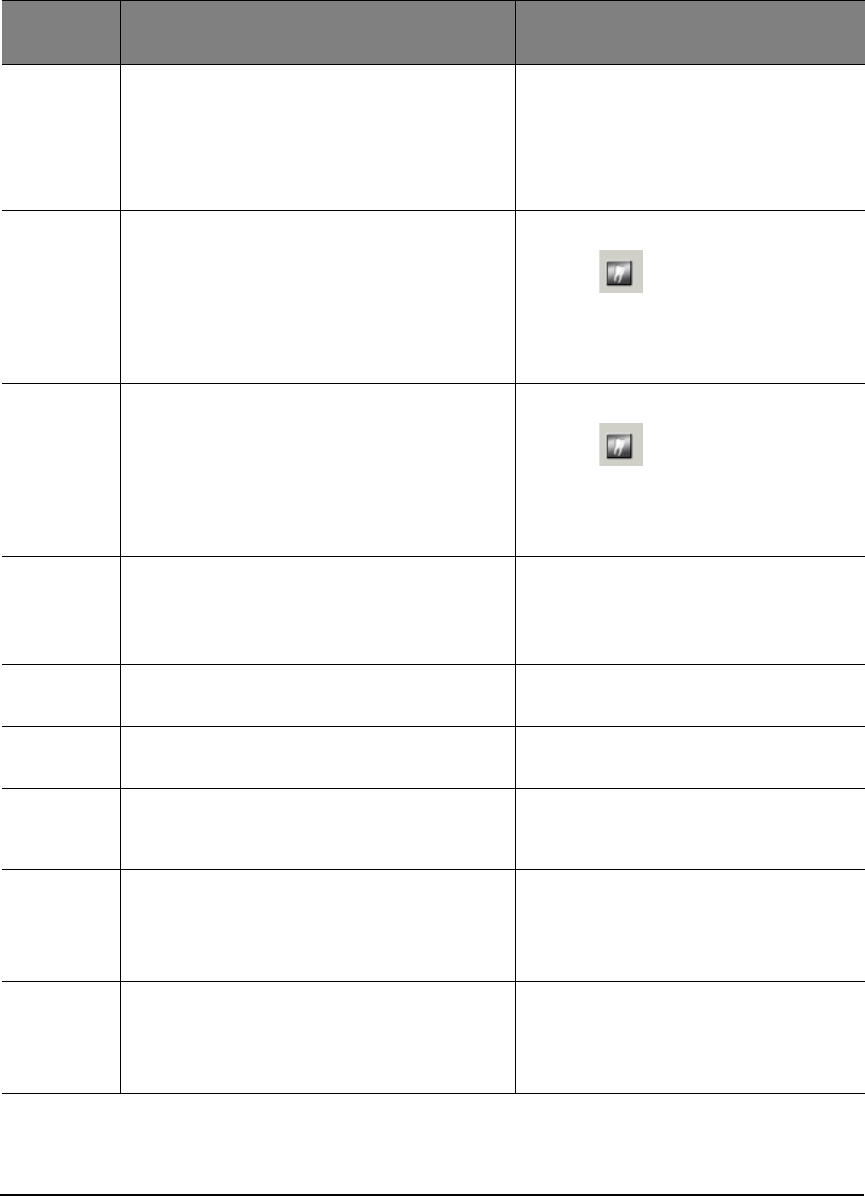
Quick Trouble Shooting
The quick trouble shooting guides you through actions you need to take to correct the malfunction.
The following table lists the malfunctions and the action to take.
Table 1 Quick Trouble Shooting
Malfunction Possible Cause Action
When you turn ON your RVG
sensor, the battery LED is red but
the control box is solid blue.
The battery needs
recharging.
Recharge the battery.
You can continue acquiring images but the
quality will deteriorate.
When you turn ON your RVG
sensor, it blinks blue then it turns
OFF.
The battery needs
recharging. Recharge the battery.
When you turn ON your RVG
sensor, the battery LED is red and
the control box is blinking red.
No battery Recharge the battery
Image quality is not good and
there are white lines on the image
The battery needs
recharging. Recharge the battery
When you turn ON your RVG
sensor, it blinks blue then after a
long time it becomes solid red.
•WiFi access point is
not ON.
•Configuration
problem.
•Check that the WiFi access point is
ON.
•If it is ON and the problem persists
contact your representative
Important: If the malfunction persists or more serious conditions
occur, contact your representative.

46 Chapter 8 Troubleshooting
When you turn ON your RVG
sensor, it blinks blue then
becomes solid blue but the sensor
cannot be found in the sensor list
on the computer.
•WiFi access point is
not ON.
•Configuration
problem.
•Check that the WiFi access point is
ON.
•If it is ON and the problem persists
contact your representative
When you turn ON your RVG
sensor, it blinks blue then
becomes solid blue but when you
press the control box button to
acquire an image it does not turn
green.
The KDIS is not open Launch the KDIS
When you turn ON your RVG
sensor, it blinks blue then
becomes solid blue but when you
press the control box button to
acquire an image it does not turn
green.
The RVG sensor is not
locked on any device. Lock the RVG sensor on the computer.
The IPS interface is frozen. The IPS aiming ring
connection problem.
•Check that the IPS aiming ring is ON
(the shut down time is 90 sec.).
•The IPS aiming ring is too far from the
RVG sensor.
•The IPS ailing ring is to close to the
RVG sensor.
When you turn ON your RVG
sensor, it blinks blue for a long
time never becoming solid blue or
solid red.
Contact your representative.
When you turn ON your RVG
sensor, it blinks blue then rapidly it
becomes solid red.
Contact your representative.
Table 1 Quick Trouble Shooting (Continued)
Malfunction Possible Cause Action
KODAK RVG 6500 System_User & Installation Guide (SM745)_Ed02 47
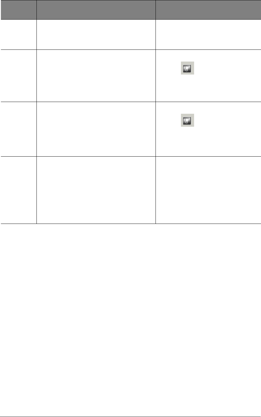
Information Messages
An information “I” error code with a message is displayed on the popup on your computer screen.
The following table lists the information messages and the action to take.
Table 2 Information Messages
Information
Error Code
Information Message Action
I 1
Communication problem with the wireless RVG
sensor. Turn off then on your sensor or restart
your computer. If the problem persists, contact
your representative.
〈Turn Off then ON the RVG sensor.
〈Or reboot your computer.
〈If the problem persists, contact your
representative.
I 2 Wireless sensor error. Turn off then on your
sensor and restart the acquisition software. If
the problem persists, contact your
representative.
1. Turn Off then ON the RVG sensor.
2. Click to access the RVG
Acquisition interface.
If the problem persists, contact your
representative.
I 3 Error during image acquisition. Turn off then on
your wireless sensor and restart the acquisition
software. If the problem persists, contact your
representative.
1. Turn Off then ON the RVG sensor.
2. Click to access the RVG
Acquisition interface.
If the problem persists, contact your
representative.
I 4 Memory allocation problem. Turn off then on your
wireless sensor. If the problem persists, contact
your representative.
Turn Off then ON the RVG sensor.
If the problem persists, contact your
representative.
I 5 Wireless sensor has storage/transmission
memory problem. Contact your representative.
Contact your representative.
I 6 Incorrect IPS calibration. Contact your
representative
Contact your representative.
I 7 IPS Batteries have run down. Change the
batteries.
Change the batteries of the IPS aiming
ring.
I 9 Writing transmission error. Turn off then on your
wireless sensor and restart the process. If the
problem persists, contact your representative.
1. Turn Off then ON the RVG sensor.
2. Redo the process
If the problem persists, contact your
representative.
I 10 Reading transmission error. Turn off then on your
wireless sensor and restart the process. If the
problem persists, contact your representative.
1. Turn Off then ON the RVG sensor.
2. Redo the process
If the problem persists, contact your
representative.
48 Chapter 8 Troubleshooting
I 12 Memory allocation problem. Restart your
computer. If the problem persists, contact your
representative.
〈Reboot your computer.
〈If the problem persists, contact your
representative.
I 13 Error during the image transfer. Turn OFF then
ON your wireless sensor and restart the
acquisition software. If the problem persists,
contact your representative.
1. Turn Off then ON the RVG sensor.
2. Click to access the RVG
Acquisition interface.
If the problem persists, contact your
representative.
I 14 System error. Close and restart the acquisition
software. If the problem persists, contact your
representative.
1. Exit the KDIS.
2. Click to access the RVG
Acquisition interface.
If the problem persists, contact your
representative.
I 15 Image storage problem in the patient database.
Check the disk space, local file system, write
access. Check the storage possibility of your
computer.
1. Check that you can access the
patient database.
2. Check the hard disk storage
availability.
3. Check if there is enough space in the
patient database.
If the problem persists, contact your
representative.
Table 2 Information Messages (Continued)
Information
Error Code
Information Message Action
KODAK RVG 6500 System_User & Installation Guide (SM745)_Ed02 49
Quick Trouble Shooting for WiFi
To minimize WiFi network malfunctions, make sure that:
•The Wi-Fi access point, in use, is the one delivered by the manufacturer with the Kodak
RVG 6500 System and Kodak RVG 6500 IPS System (Netgear WGR614).
•The computer in use, has at least the requirements listed in KODAK RVG 6500
System_Regulatory User Guide (SM737)_Ed01B, Chapter 3.
•The installation and configuration of the network has been done following the steps given
in Chapter 5 of this document.
•The distance between different elements of the configuration is respected (See Chapter 5
of this document).
To correct the malfunction of your WiFi network, follow these steps:
1Turn OFF the WiFi access point.
2Turn OFF the RVG sensor control box.
3Turn ON the WiFi access point and wait a minute and check that:
• is on.
• is on. Then goes off when the system is ready and running.
• is on.
4Press the remote control button of the RVG control box to turn ON the device. The blinking blue
light indicates the sensor attempt to connect to the WiFi access point. Wait for the blinking blue
light (A) to become solid blue. (B) The sensor is connected to the WiFi access point.
5If the sensor cannot connect to the WiFi access point, see Tables 2 and 3.
6If the WiFi access point functions correctly but cannot connect to your computer, see your
computer’s Troubleshooting section.
A
B

50 Chapter 8 Troubleshooting
KODAK RVG 6500 System_User & Installation Guide (SM745)_Ed02 51
9 Maintenance
This chapter describes the maintenance task that you need to perform regularly for your KODAK RVG
6500 with or without IPS system and the accessories.
Daily
The RVG Sensor
The RVG sensor is supplied in a non-sterile state. Single-use disposable protective hygienic sleeves
must cover the RVG sensor before placing it in the patient’s mouth. These sleeves are conform to the
ISO EN 10993.
To prevent cross-contamination, use a new hygienic barrier for each new patient and disinfect the RVG
sensor.
Cleaning and Disinfecting the RVG Sensor
You must first clean the RVG sensor before disinfecting it. To do so, follow these steps:
1Remove the protective hygienic sleeves.
2Remove debris or organic matter from the sensor surfaces with a disposable wipe or surface
brush.
3Inspect the sensor for debris. Repeat cleaning if there is any debris left.
4Clean and disinfect with disinfecting wipes.
If you choose disinfecting solutions, use disinfectant suitable for medical devices and composed
of Ethanol and/or Isopropanol, and/or Quaternary ammonium (follow the chemical manufacturer’s
instruction).
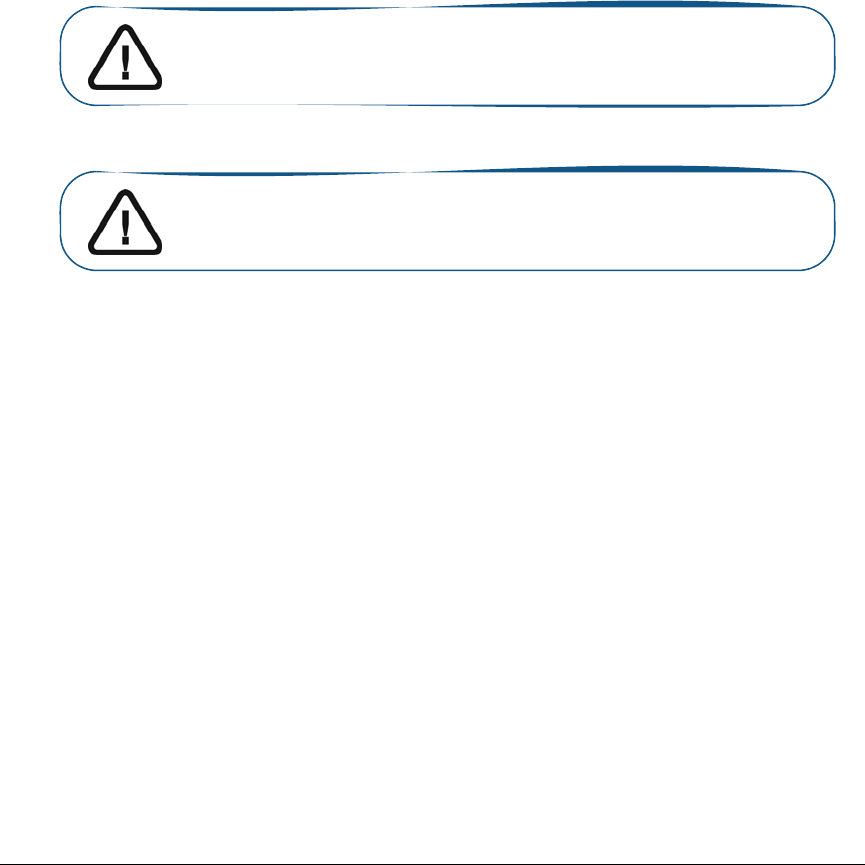
WARNING: Never place the sensor and/or control box in an autoclave
as this could result in serious damage to the sensor.
WARNING: You must first clean the RVG sensor before disinfecting it.
52 Chapter 9 Maintenance
Cleaning the RVG Sensor Control Box
The RVG sensor control box must be cleaned with disposable cleaning wipes similar to those used for
the computer screens.
.
Cleaning the Positioning Accessories
.
Monthly
Wipe the outer covers of the WiFi AP with a soft and dry cloth.
Table 3 Positioning Accessories Daily Maintenance Tasks
Accessories Maintenance Tasks
Toothbrush holders 1. Remove any residue with hot water and soap.
2. Put the metal and plastic parts in separate sterilization pouch and
autoclave up to 132°C (273° F) before the next patient.
Bite blocks
RINN Arm & ring
1. Disassemble the metal arm and the plastic ring.
2. Remove any residue with hot water and soap.
3. Put the metal and plastic parts in separate sterilization pouch and
autoclave up to 132°C (273° F) before the next patient.
IPS aiming ring Wipe clean with disposable cleaning wipes.
WARNING: Never immerse the RVG sensor control box in any solution.
WARNING: Do not use chemical autoclave for the toothbrush holders
and avoid direct contact with the metallic part of the autoclave.
KODAK RVG 6500 System_User & Installation Guide (SM745)_Ed02 53
Replacing the RVG Battery
To replace the RVG battery, follow these steps:
1Turn OFF the RVG sensor.
2Make sure that the RVG sensor is not connected to the mains outlet.
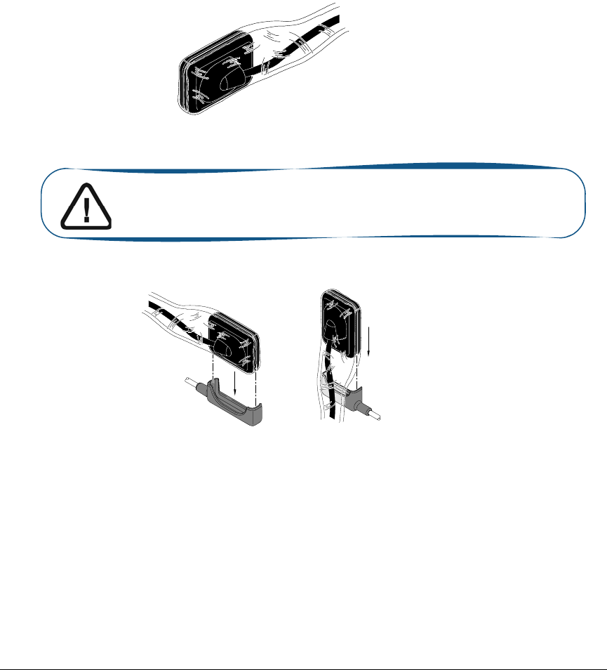
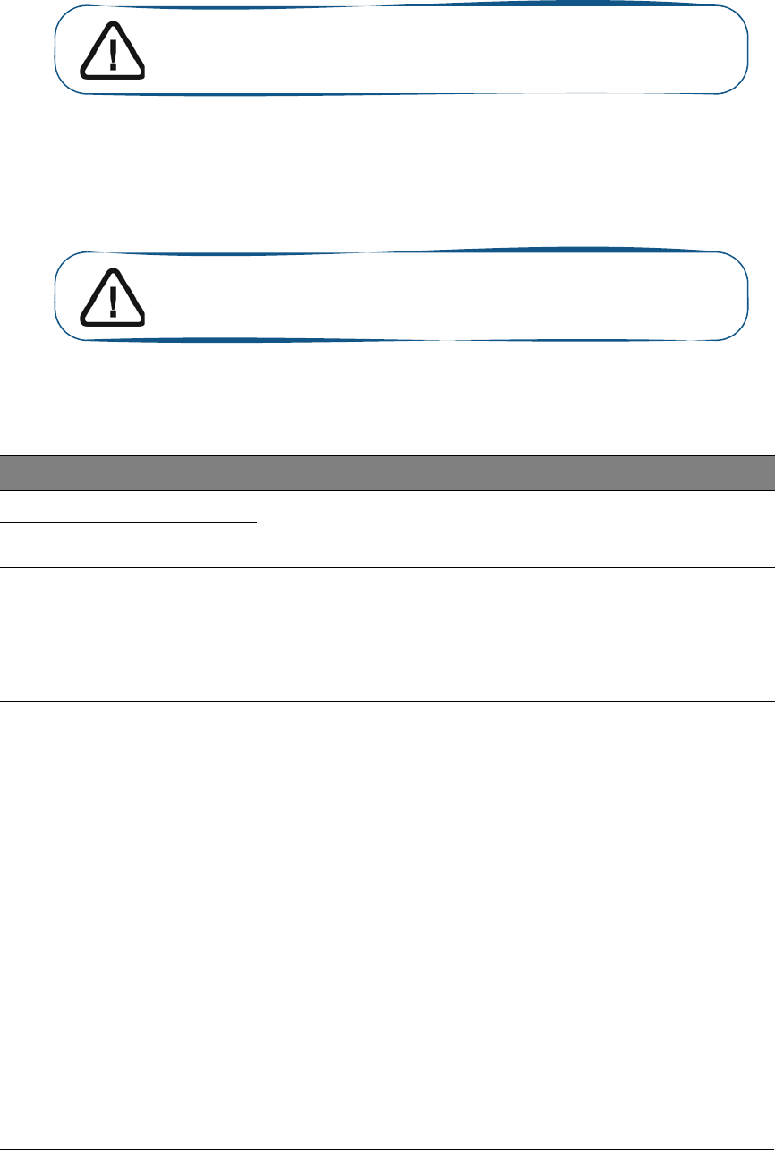
3Press down with fingers and slide the trap door (A) protecting the battery on the back of the
control box.
4Remove carefully the connector (B) to remove the used battery.
5Insert the connector (B) of the appropriate battery.
6Slide and close the trap door (A) protecting the battery.
RVG Control Box
A
A
WARNING: Make sure that the battery is inserted correctly in its
connector.
A
B
54 Chapter 9 Maintenance
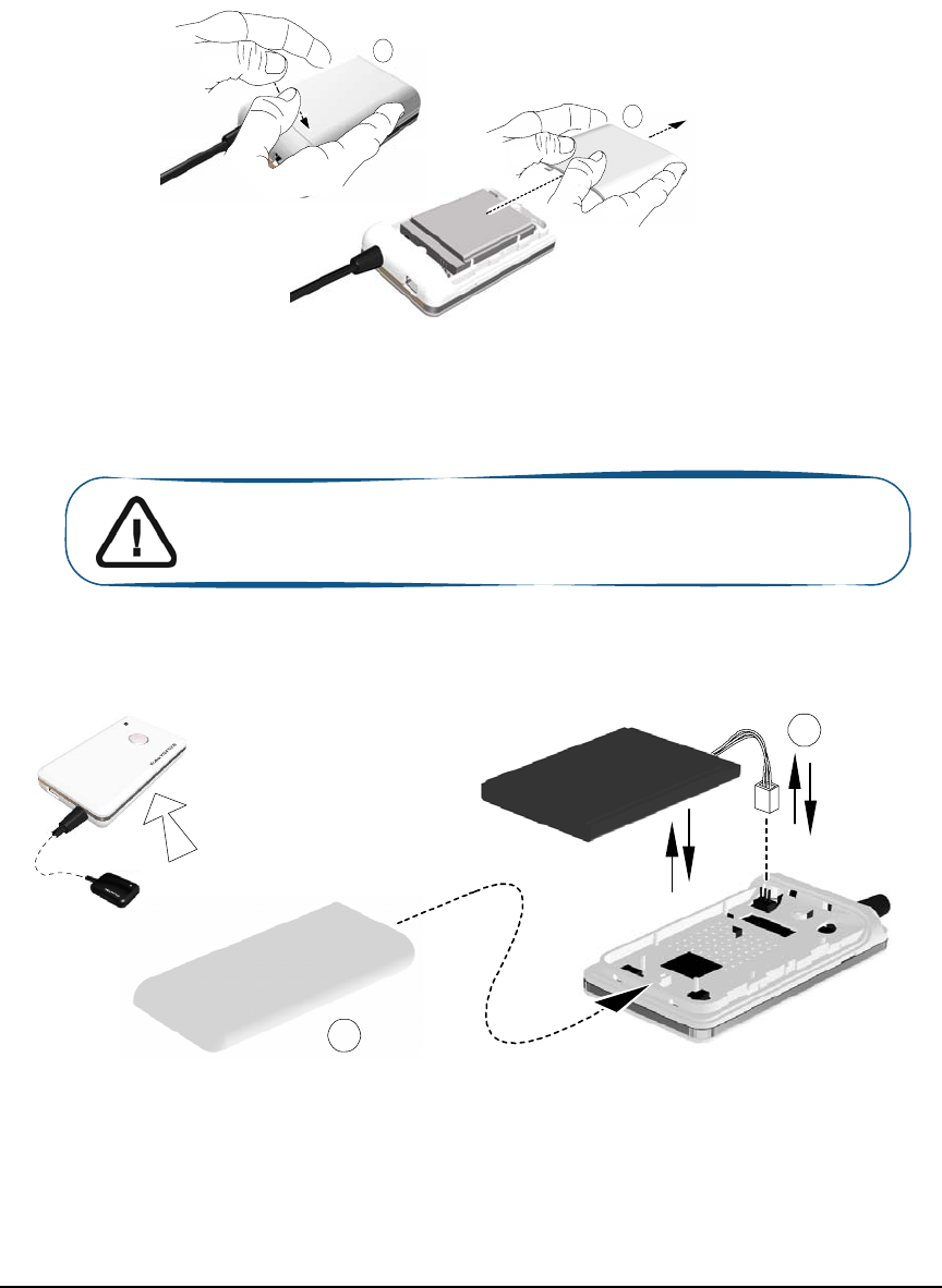
RVG Control Box with IPS board
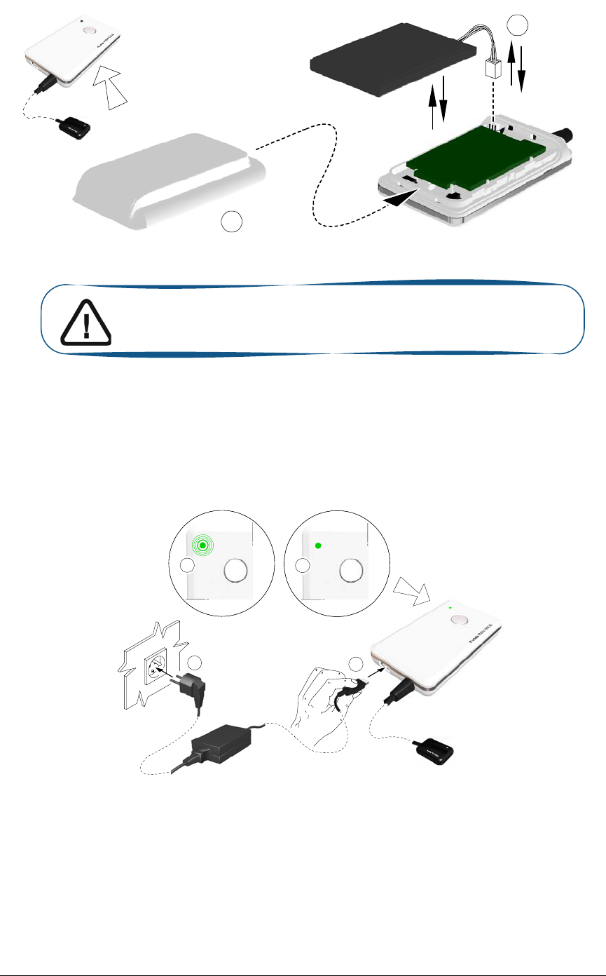
7Plug one end of the medical charger in the USB port of the RVG control box.
8Plug the other end to the mains outlet.
The blinking green light of the battery status (A) on the control box indicates the charging process.
The first charging takes about 4hours. When the green light becomes solid green (B) the charging
is complete.
With a fully charged battery you can acquire 180 images.
A
B
Important: For the RVG with IPS board, make sure that you insert
the battery gently avoiding any damage to the IPS board.
B
21
A
KODAK RVG 6500 System_User & Installation Guide (SM745)_Ed02 55
9You can use the USB cable to charge RVG battery with the computer.
Important: You can use the RVG sensor to acquire an image while
charging ONLY with the medical charger.
WARNING: NEVER use the RVG sensor to acquire an image while
charging with the USB cable.
Important: Remove the battery from the control box if you will not
use it for a long period of time.
56 Chapter 9 Maintenance
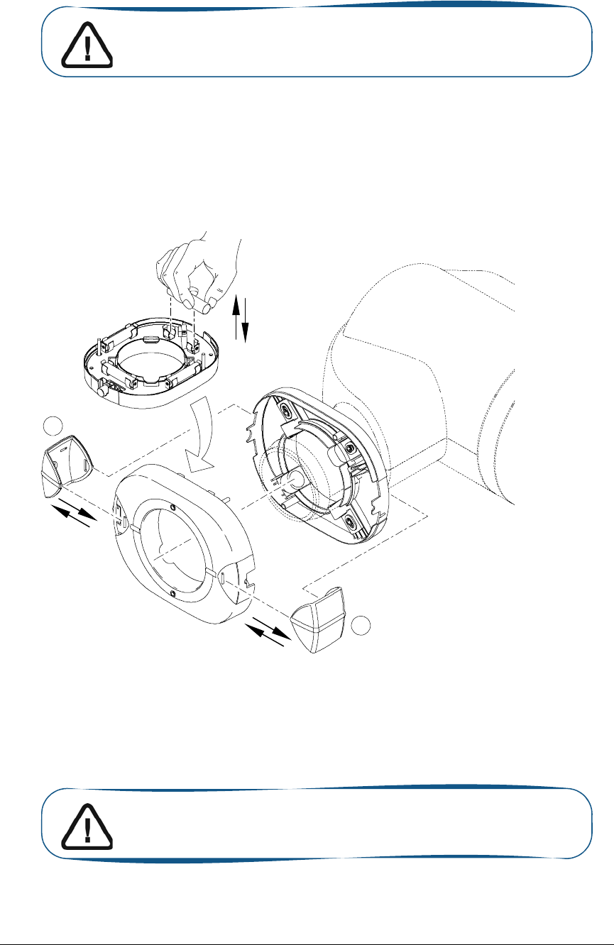
Replacing the IPS Aiming Ring Battery
To replace the IPS aiming ring battery, follow these steps:
1Remove the attachment brackets (A).
2Remover the front cover.
3Remove the used 4 batteries.
4Replace correctly the new 4 batteries respecting the polarities.
5Replace the front cover.
6Replace the attachment brackets (A).
7Turn ON the IPS aiming ring to check that the batteries are replaced correctly.
Important: When the battery is low the LEDs light becomes orange.
You need to replace the IPS battery.
A
A
x4
Important: Remove the battery from the IPS aiming ring if you will
not use it for a long period of time.