Carnegie Robotics 00068 Platform Module User Manual 56091197a English indd
Carnegie Robotics LLC Platform Module 56091197a English indd
Contents
- 1. Operator Manual Part 1
- 2. Operator Manual Part 2
Operator Manual Part 2
12/2017 A - 31 56091197 - Nilfi sk Liberty SC50
ENGLISH - AINSTRUCTIONS FOR USE
9/2018
CB2
5A
CB3
15A
CB1
5A K1
1A
3A
2A
4A
X6
X8 X8
X7
X8
X7 X22
X17
X
AA
3
Z
A
B
MJ
J1 K
K1 O
YY1
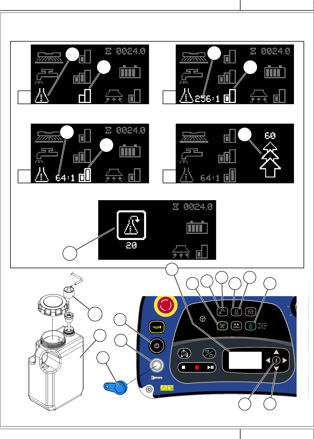
DETERGENT SYSTEM PREPARATION AND USE (ECOFLEX)
FIGURE 2-10
Chemical Free Cleaning Mode / Detergent Off Detergent Low Mode
Detergent High Mode Burst of Power Cleaning Mode
Purge
Press and hold (J) & (K)
for 2 seconds to purge.
A - 32 Nilfi sk Liberty SC50 - 56091197 12/2017
INSTRUCTIONS FOR USEA - ENGLISH 9/2018
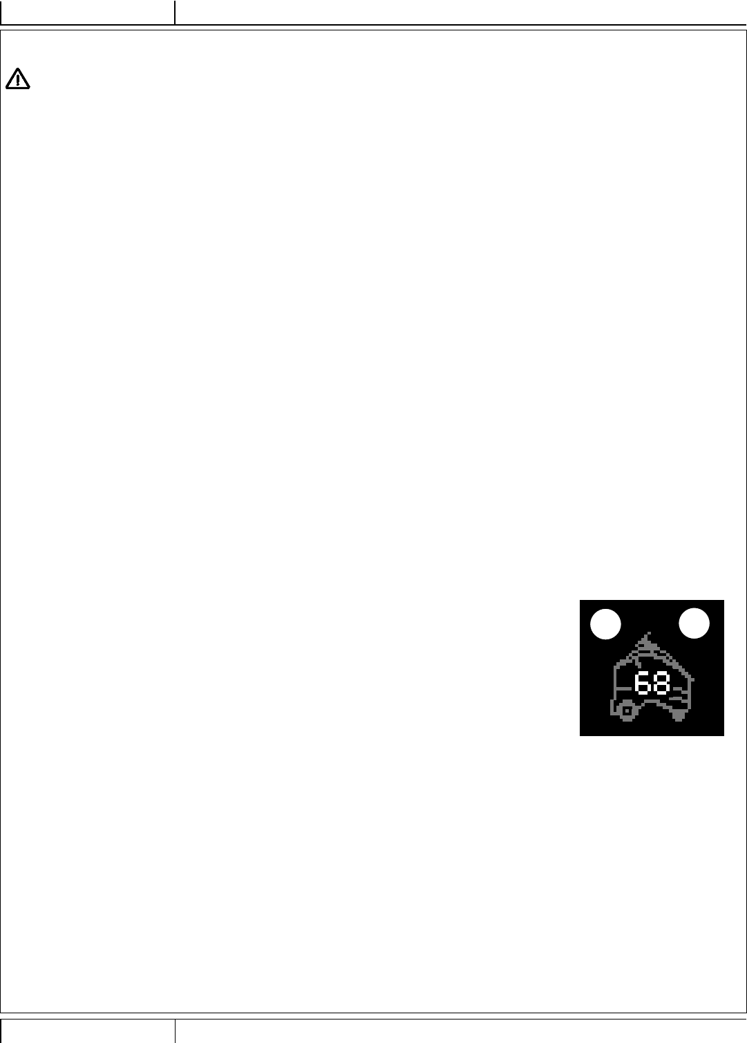
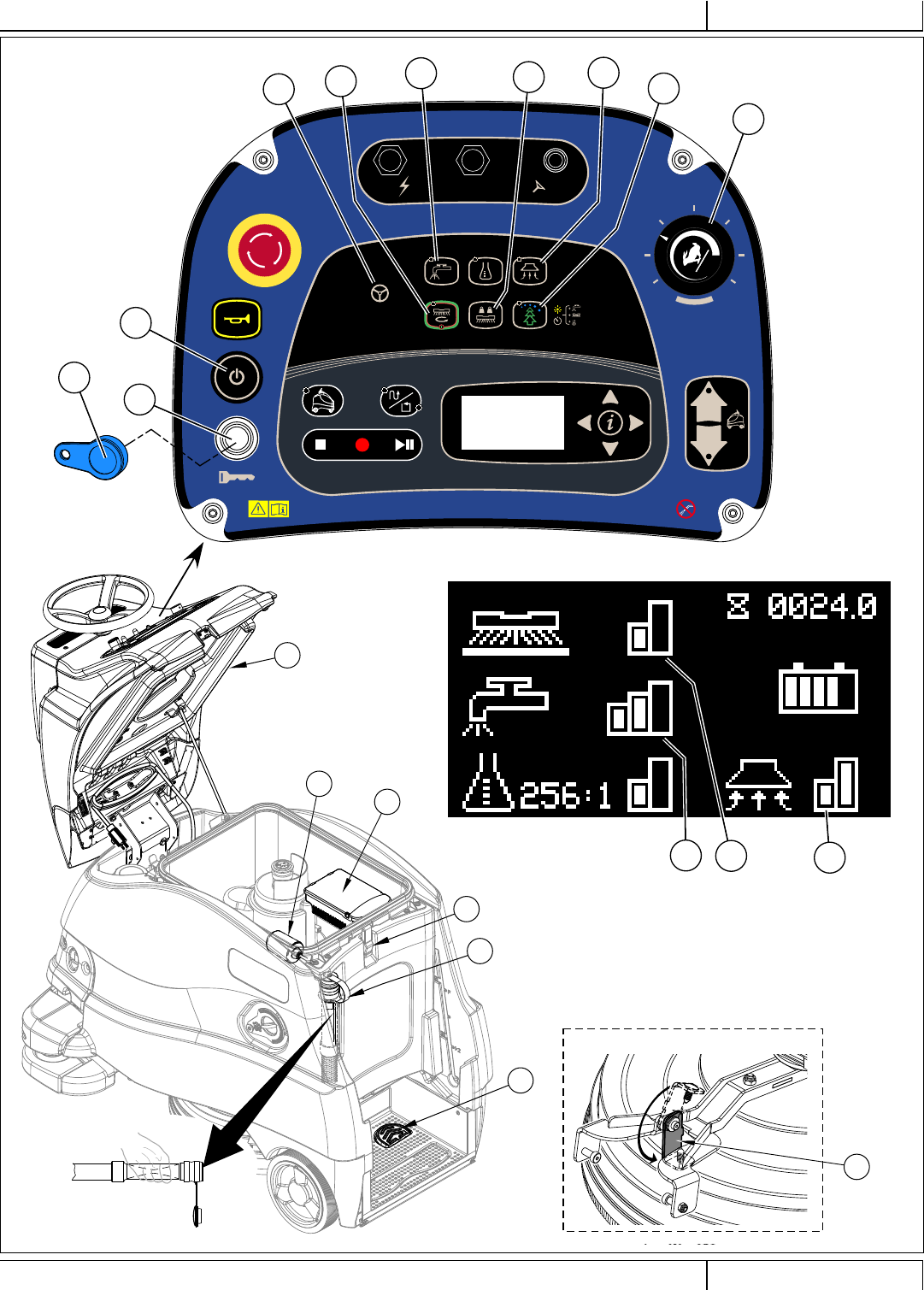
2 See Figure 3-1. Step onto the Platform (26) compressing Operator’s Presence Pedal (25). NOTE: Do not press the
Go Pedal (24) until you are ready to move the machine.
3 Place the Magnetic SmartKey (Z) onto the SmartKey Reader (A). Press the Power Switch (B). This will activate the
Display (X). Wait for the start-up sequence to fi nish.
NOTE: At startup, the machine conducts a system self-test for the Autonomous Operating Mode. This test takes
about 70 seconds to complete in order to get values from the lasers. Display will indicate the system is booting
by showing Autonomous Indicator along with a Countdown Timer (X25 & X26) during the startup sequence. If the
system fails to boot the countdown timer will be replaced by a question mark “?” for a few seconds then machine will
display a fault code and go into manual mode.
Before startup, make sure there are no obstacles within 2’ (0.6m) of the machine. Operators must stand directly
behind the machine during startup to be clear of all sensors.
4 Reference the Battery Condition Indicator (X3) and check for any Fault Codes (X2) before proceeding.
5 The Manual Operation Indicator (H) will be lit.
6 To transport the machine to the work area, fi rst push the Forward Drive Switch (Q) or Reverse Drive Switch (R) to select the direction of travel and
then apply pressure with your foot on the Go Pedal (24). An audible alert from the speaker will sound in reverse.
NOTE: Stepping off of the Operator’s Presence Pedal (25) for more than 2 seconds will cause the Forward or Reverse Drive Switch Indicator to turn
off. The operator will need to select forward or reverse again before the machine can be driven.
7 Adjust machine speed by rotating the Speed Adjustment Knob (P) clockwise to go faster or counterclockwise to go slower.
NOTE: While the machine is operating in autonomous mode the machine’s speed is set by the computer and not adjustable by using the speed
adjustment knob.
OPERATING THE MACHINE
WARNING!
Be sure you understand the operator controls and their functions.
While on ramps or inclines, avoid sudden stops. Avoid abrupt sharp turns. Use low speed down ramps.
Do not operate autonomously when ambient RF signal falls at or near the frequency range of 340 MHz to 460 MHz.
Operating Modes
The Nilfi sk Liberty SC50 has three operating modes:
• Manual Operating Mode: Provides normal functioning of the machine, without autonomy. In this mode the machine is driven and controlled by an operator,
and operates in a conventional manner. The machine must be driven in the manual mode while creating plans the machine will follow during Autonomous
Operation. This includes driving to and from the autonomous scrubbing plans (locations). Full details of the Manual Operating Mode are contained in the
OPERATING THE MACHINE MANUAL MODE section of this manual.
• Autonomous Mode: The Autonomous Operating Mode is used to perform scrubbing operations automatically, without active Operator involvement. This is
done by training the machine to follow a specifi c plan or perimeter of an area.
- Plans may also include specifi c actions the machine will make while performing the scrubbing activity. Such actions might include knowing when to raise
or lower the scrub deck, how much solution to dispense. When played back, the plan tells the machine exactly what to do; what path it should follow, and
what scrubbing actions it should take along the way.
- To operate autonomously, the machine needs to always know exactly where it is in relation to the recorded plan, and the operating environment. This
mapping process operates constantly, in every operating mode, whenever the machine is turned on.
• Training Mode: Used to create plans (either CopyCat™ or Fill-In) the machine will follow when scrubbing autonomously. Before the machine can operate
autonomously, it must be trained to follow a specifi c plan(s) while scrubbing. During training, both the plan and required actions are recorded and saved.
STARTING THE MACHINE
1 Follow the instructions in “Preparing the Machine for Use” section of this manual and verify the following;
• Exterior of machine is free of damage. Report any damage to your supervisor.
• Proper brush/pad is correctly installed.
• Squeegee is installed.
• Camera and laser lenses are clean, see CLEAN SENSOR LENSES section.
• Batteries are fully charged.
• Solution tank is full.
• Recovery tank is empty.
• Location tag is properly installed to a wall
• Home Position is set (required for autonomous operation).
• Ensure that area to be scrubbed is clear of obstacles that are not fi xed, such as hoses, buckets or pails, boxes, electrical cords, carts, pallets, etc.
X25 X26
12/2017 A - 33 56091197 - Nilfi sk Liberty SC50
ENGLISH - AINSTRUCTIONS FOR USE
9/2018
STOPPING THE MACHINE
1 Stop the machine by releasing the Go Pedal (24) while operating in Manual Mode.
2 In Autonomous Mode machine can be stopped by one of the following methods;
• Pressing the Remote Pause Button (AD)
• Stepping onto the Operator Presence Pedal (25), (this will temporarily stop machine, if operator stays on machine for 30 seconds it will exit autonomous
mode)
• Pressing the Stop Switch (T) or the Play/Pause Switch (V)
NOTE: The electromagnetic brake built into the drive wheel is engaged automatically when the Go Pedal is not pressed (or in autonomous mode when
machine stops playback).
CAUTION!
In the event of an emergency, to stop all machine functions immediately, press the Emergency Stop Knob (D).
The display will show the Emergency Stop Activated Indicator (X18). To reset the machine functions, rotate the emergency stop knob clockwise.
FIGURE 3-1
24
26
25 X3
X2
X18
CB2
5A
CB3
15A
CB1
5A K1
A
P
B
ZQ
R
X
AD
D
H
A - 34 Nilfi sk Liberty SC50 - 56091197 12/2017
INSTRUCTIONS FOR USEA - ENGLISH 9/2018
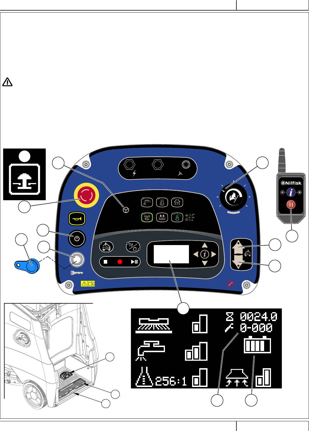
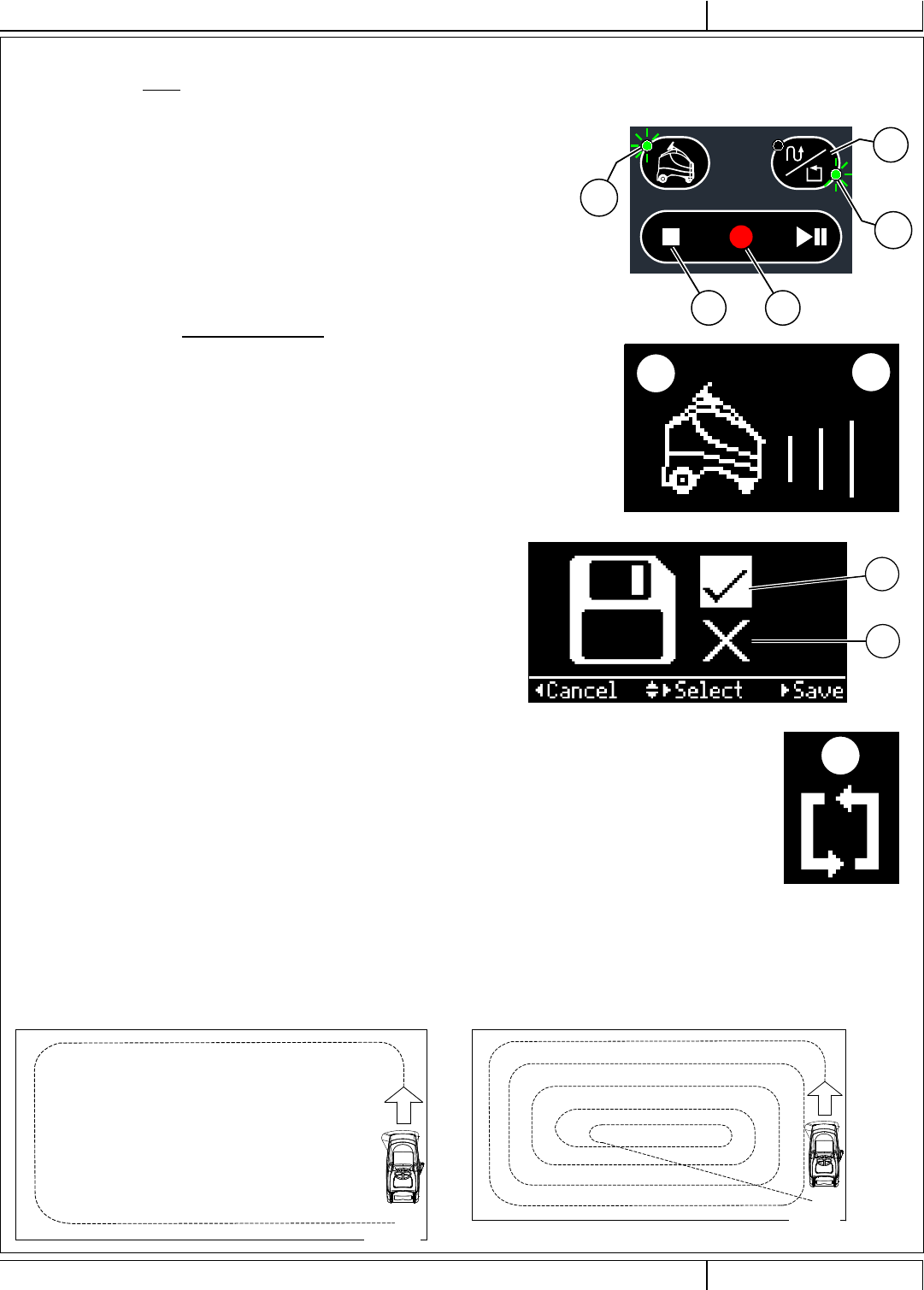
TRAINING/RECORD CopyCat™...
1 Press CopyCat/Fill-in Switch (W) so that CopyCat LED (W1) is lit. This indicates
machine has entered the CopyCat mode and is ready to begin training.
2 Press Record Switch (U).
a. Autonomous Mode Indicator (S1) will be lit.
b. Screen displays Autonomous Indicator along with Advancing Lines (X25 & X28)
to indicate machine is in training mode.
c. LED Status Bar (4) will emit a slow fl ashing green light.
3 Clean the area as desired using the vacuum, solution, scrub and detergent settings
you want.
- While training CopyCat;
a. Operate all of the scrub functions. Clean the fl oor as you would on a manual
machine. See section “OPERATING THE MACHINE MANUAL MODE” for
more information on adjusting any of the scrub settings. The machine will
record every action of the operator including adjustments to scrub settings, use
of the horn and remember the route traveled See Figure 3-2.
b. The reverse switch is not selectable while training.
TRAINING THE MACHINE FOR AUTONOMOUS MODE
1 There are two types of autonomous plans. To change between the two types press the CopyCat™/Fill-In Switch (W).
a. CopyCat™ – Machine will follow the same plan driven by the operator (default setting). The CopyCat Mode is used to stage scrubbing in
hallways, aisles, and irregular-shaped areas.
b. Fill-In – Operator must drive the machine in a counter-clockwise plan around the perimeter of an area and the machine will clean the area
contained within this closed plan (start and stop at the same point). The Fill-In Mode is used when scrubbing inside rooms or other confi ned
areas. The Fill-In Mode is also well suited for scrubbing straight hallways that are at least 4 machine widths wide.
2 Follow the instructions in “Starting the Machine” section and manually drive the machine to the starting point for training.
X
4 When fi nished CopyCat training, press the Stop Switch (T)
or Record Switch (U), to stop training. Pressing either button
brings up a menu with the options to save or cancel the plan.
a. Use the up and down navigation arrows (Y1) to choose
between;
• “ ” (X39) to Save the plan
• “ X ” (X40) to cancel the plan
b. Press the right arrow to select the option
c. Or press left arrow to exit and continue training
5 Display will show Computer Processing Indicator (X30)
while computer is compiling/saving the plan. Do not move
machine while plan is being saved. This may take several
minutes.
6 Machine indicates if recording was successful or failed.
d. If plan saves successfully the screen will briefl y display
CopyCat Plan Saved Indicator (X33).
e. If plan fails to save the screen will display a fault
7 Machine LED Status Bar will change from green to OFF or
ON white (optional setting).
FIGURE 3-2
W
W1
U
T
S1
X25 X28
X39
X40
X30
12/2017 A - 35 56091197 - Nilfi sk Liberty SC50
ENGLISH - AINSTRUCTIONS FOR USE
9/2018
1. Press and release CopyCat/Fill-In Switch (W) until Fill-In LED (W2) is lit. This
indicates machine has entered the Fill-In mode and is ready to begin training.
2. Select the scrub settings to be used for the whole Fill-In plan. See section
“OPERATING THE MACHINE MANUAL MODE” for more information on
adjusting any of the scrub settings. Once the record switch is pressed these
settings will be remembered and applied to the whole Fill-In upon playback.
3. Press Record Switch (U).
a. Autonomous Mode Indicator (S1) will be lit.
b. Screen displays Autonomous Indicator along with Advancing Lines (X25 & X28)
to indicate machine is in training mode.
c. LED Status Bar (4) will emit a slow fl ashing green light.
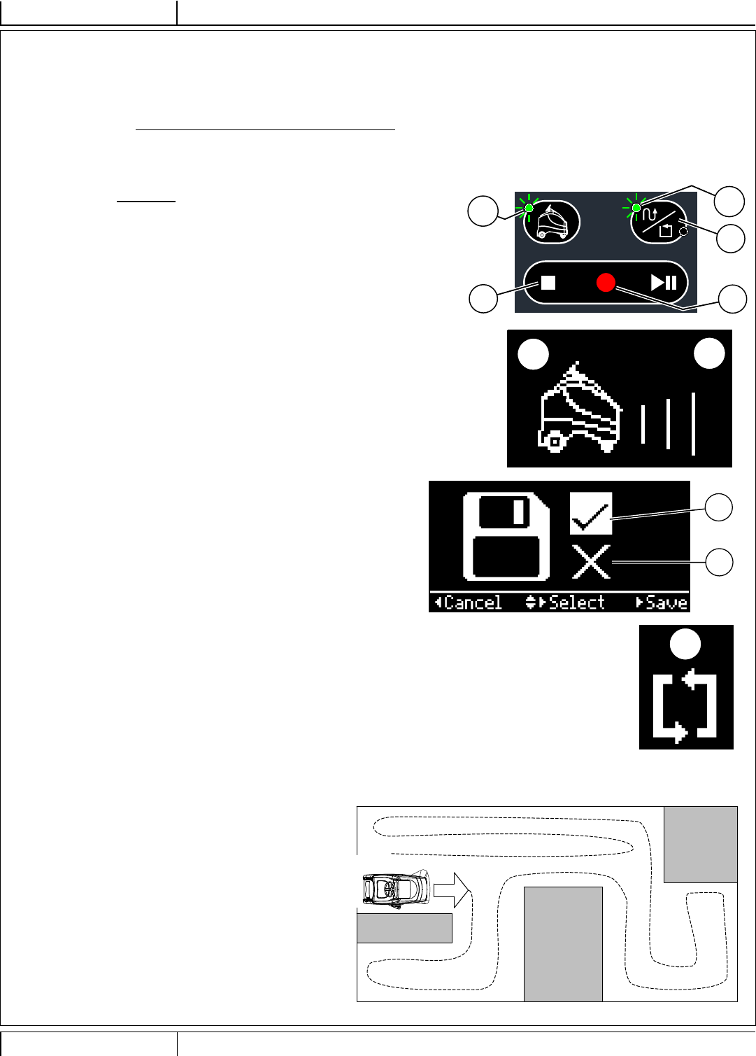
4. Drive the machine in a counter-clockwise plan around the perimeter of the area
to be cleaned. When creating a plan (training) in the Fill-in Mode, the right side
of the machine must be towards the wall and the 2-D Laser Scanner pointed
towards the center of the room. From the starting point, movement must be in a
counterclockwise direction.
- While training Fill-In;
a. The reverse switch is not selectable while training.
5. Drive the machine around the perimeter of the area to be cleaned and drive back
through the starting point and continue along the plan another 25 feet a second time
TRAINING THE MACHINE FOR AUTONOMOUS MODE - CONTINUED
TRAINING/RECORD Fill-In...
W
W2
U
T
S1
X
until the machine stops on its own. See Figure 3-3. NOTE: When the Fill-In
plan is being played back the machine will use an algorithm to create a plan
that covers the entire area and ends back at the starting point. See Figure
3-4.
6. Machine will indicate it is close to the starting point by emitting two
beeps.
7. When fi nished Fill-In training, press the Stop Switch (T) or Record
Switch (U), to stop training. Pressing either button brings up a menu
with the options to save or cancel the path.
a. Use the up and down navigation arrows (Y1) to choose between;
• “ ” (X39) to Save the plan
• “ X ” (X40) to cancel the plan
b. Press the right arrow to select the option
8. Display will show Computer Processing Indicator (X30) while computer is
compiling/saving the plan. Do not move machine while plan is being saved.
This may take several minutes.
9. Machine indicates if recording was successful or Failed.
a. If plan saves successfully the screen will briefl y display Fill-In Plan
Saved Indicator (X37).
b. If plan fails to save the screen will alternate between icons Fill-In Plan
Indicator & Fill-In Plan Failed Indicator (X35 & X36).
10. Machine LED Status Bar will change from green to OFF or ON white
(optional setting).
X
FIGURE 3-4
FIGURE 3-3
X25 X28
X39
X40
X30

A - 36 Nilfi sk Liberty SC50 - 56091197 12/2017
INSTRUCTIONS FOR USEA - ENGLISH 9/2018
TRAINING THE MACHINE FOR AUTONOMOUS MODE - CONTINUED
WHILE TRAINING/RECORDING IN COPYCAT OR FILL-IN MODES...
Operator is interrupted
1 If operator is interrupted during the recording process, release foot from Go Pedal to stop machine and step off the machine to stop all
functions. If operator steps off the machine at any time during the record process the machine will stop.
2 Remove the magnetic SmartKey and attend to other issues.
3 After returning step back onto the machine, replace the SmartKey and press the Record Switch (U) to resume training.
Training needs to be stopped
1 If training needs to be stopped during the recording process (to re-fi ll solution tank, empty recovery tank etc.) release foot from Go Pedal to
stop machine movement and press the Play/Pause Switch (T) to stop recording.
2 The machine will not remember where it left off training and plan must be re-recorded. After emptying recovery tank, refi lling solution etc.,
return to starting point and re-train the plan.
Important to Know About Training a Plan
• Be mindful of where you start a plan so it’s not in a busy or congested area, but also in a logical place to start cleaning. Start point should
be in a location that’s easy to remember and get to in the future since machine will need to start there each time to playback.
• Be mindful of where you will end the plan (only for CopyCat) so that machine is not blocking a doorway or otherwise in the way when it
comes to a stop at the end of the plan.
• Train plan with the left side of the machine facing into the room.
• Two plans cannot have the same starting point. If two starting points are close to each other the machine will playback the plan which has
the starting point nearest to the machine. Any two starting points should be a minimum of 8 ft. (2.4m) apart.
• For CopyCat plans the start and end points do not need to be the same location.
Results of Training a Plan Include
• Saved plan guides machine movements during autonomous operation.
• Machine will follow exact plan(s) recorded, avoiding known obstacles identifi ed on plan.
• Machine will drive around new obstacles detected but not recorded.
• Machine will signal the remote to notify Operator if there are problems or machine cannot move around newly detected obstacles.
• Machine will signal the remote when the machine has fi nished cleaning and reached the end of the plan.
DELETE A PLAN
1 Cancel Current Recording:
a. During training press Stop Switch (T) at any time to bring up a menu which allows the operator to cancel/delete the current plan being
trained.
2 Delete Existing Plan:
a. Drive machine to the start area of the plan.
b. Machine will recognize the plan by an audible alert (2 beeps), lighting the appropriate LED either CopyCat or Fill-In that corresponds to
the plan.
c. Press Autonomous Switch (S) to enter Autonomous menu choose “Delete this plan”.
12/2017 A - 37 56091197 - Nilfi sk Liberty SC50
ENGLISH - AINSTRUCTIONS FOR USE
9/2018
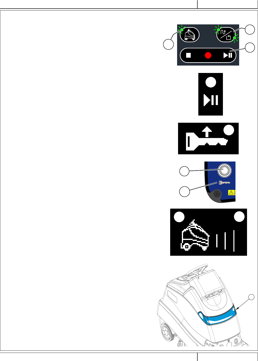
PLAYBACK OF RECORDED PLAN, AUTONOMOUS MODE
Once the operator has recorded a plan (training complete) in an area playback is possible. W
V
S1
1 Follow the steps under “Starting the Machine”. Drive machine to the start area of a
trained plan.
2 Machine will indicate it has a viable cleaning plan for the area in which the machine is
currently located. Signal is audible and visual.
a. When within 6 ft. (2 m) of a start point for a trained plan machine will emit two
beeps. When driving through a start area machine will emit one beep as it drives
out of the start area.
b. The Autonomous Indicator (S1) will fl ash.
c. The LEDs on CopyCat/Fill-In Switch (W) will light to indicate which cleaning plan
mode is available from this location.
d. Display will show (X29) if playback is available. If (X13) is displayed, playback is
not available due to batteries not having enough charge to allow playback.
3 Scrub settings;
a. Machine will scrub with the scrub settings used while training the plan.
4 Press the Play Switch (V). Machine will display Autonomous Mode Indicator (X25) to
indicate playback is ready.
5 Step off of the machine.
6 Remove the magnetic SmartKey from the machine. Machine will display (X38)
(fl ashing arrow) and blink the LED (A1) below the SmartKey Reader (A) to indicate
operator must remove the magnetic key from the machine before playback can begin.
7 At the start of playback the horn will sound for two seconds, LED bar will turn blue and
then machine will begin scrubbing.
8 While the machine is cleaning in autonomous mode the following will be observed;
a. Autonomous Indicator along with Advancing Lines (X25 & X28) will be on the
display.
b. An audible ‘heartbeat’ sound will be emitted.
c. LED Status Bar (4) will be slow fl ashing blue. While executing a turn the LED
Status Bar will fl ash yellow on either side to indicate the direction of the turn.
LED Status Bar will change to chasing red if someone walks in front of the
machine or encounters an unmapped obstruction.
9 When machine gets to the end of the recorded plan;
a. Scrub brushes and solution fl ow will stop and the scrub deck will raise up.
Machine will continue to travel a short distance to pick up remaining water.
b. The squeegee will raise up after a brief delay with the scrub deck and the
vacuum will stop after an additional delay (this is to allow any remaining water to
be picked up without turning the vacuum back on).
c. Machine will signal the remote. Flash red LED and beep every 2 minutes to
notify operator should return to machine.
d. After a set time the machine will enter a sleep mode to save battery power.
FIGURE 3-5
4
A
A1
X29
X38
X25 X28
A - 38 Nilfi sk Liberty SC50 - 56091197 12/2017
INSTRUCTIONS FOR USEA - ENGLISH 9/2018
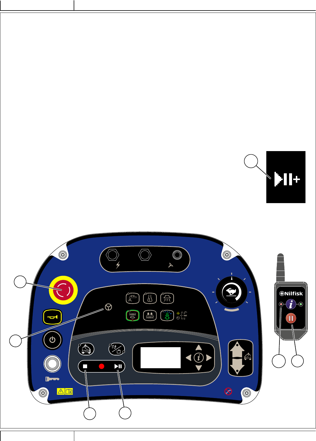
PLAYBACK OF RECORDED PLAN, AUTONOMOUS MODE - CONTINUED
IMPORTANT TO KNOW WHILE IN PLAYBACK MODE
• If the Stop Switch (T) is pressed the machine will stop and go into manual mode.
• If the Pause Switch (V) is pressed the machine will pause playback. Place the SmartKey back on the reader and press Pause Switch (V)
again, then remove SmartKey to resume playback.
• If the Emergency Stop (D) is pressed the machine will stop immediately and go into manual mode.
• All other switches (and speed control knob) are “locked out” pressing them will have no effect.
While in Playback Mode...
Operator needs to interrupt autonomy to Take-Over Cleaning
1 While machine is cleaning in autonomous mode. Operator can approach the machine with the remote.
2 Press the Remote Pause Button (AD). The Remote Status Indicator (AC1) will turn red.
3 Machine stops/pauses project – lifts scrub deck, stops solution/detergent fl ow, travels a bit further to vacuum water, lifts squeegee/stops vac.
4 Operator steps onto machine and inserts SmartKey.
5 Machine signals that operator now has control of machine by lighting Manual Operation Indicator (H).
6 Operator can now drive/operate machine as needed in manual mode.
Playback needs to be paused/resumed
1 If autonomous scrubbing needs to be interrupted during the playback of a plan (to re-fi ll solution tank,
empty recovery tank etc.) press the Remote Pause Button (AD) to stop machine movement and stop all
functions. The machine will remember where it left off playback and create a temporary “resume area”.
Make note of this location to return here.
2 Go empty recovery tank, refi ll solution etc.
3 After returning to where the recording was paused, the machine will beep twice and display Resume Plan
Available Indicator (X33) as it enters the “resume area”. Press the Play Switch (V) to resume and fi nish
cleaning the plan.
FIGURE 3-6
CB2
5A
CB3
15A
CB1
5A K1
H
D
TV
AD
AC1
X33
12/2017 A - 39 56091197 - Nilfi sk Liberty SC50
ENGLISH - AINSTRUCTIONS FOR USE
9/2018
PLAYBACK OF RECORDED PLAN, AUTONOMOUS MODE - CONTINUED
Machine Encounters an Issue While Cleaning in Autonomous Mode
1 While machine is successfully cleaning in autonomous mode. Machine may encounter any one of the scenarios listed below;
a. Obstacle – Does NOT Move
b. Machine is Blocked – CANNOT Plan Around
c. Machine needs to locate Home Position
d. Machine System Crash
e. Machine Battery Level Low
f. Solution Tank Empty
g. Recovery Tank Full
h. Repeated Obstacles Continuously Disturb machine
i. Person steps onto machine for longer than 30 seconds
j. Sensors Blocked
k. Machine is Impacted/Hit by Other Vehicle/Person/Obstacle, etc.
l. E-Stop Button Pressed
m. Serious Scrubber Fault Code
2 In all cases the machine stops moving, the scrub deck stops and raises to the vac only height and the vacuum will run briefl y until it times out.
Then all functions turn off and the remote will be signaled of an error. The remote will beep and show Red LED (AC1) if error occurs.
3 Operator must return to the machine to clear/eliminate error. SmartKey must be placed on reader to access menu or restart.
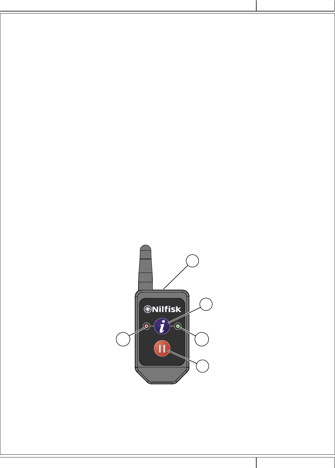
Operator Monitors Machine Progress via Remote...
1 While machine is successfully cleaning in autonomous mode the operator can get feedback on its status through the remote.
a. Remote includes one RED LED (AC1) and one GREEN LED (AC2).
b. Operator can press the Remote Information Button (AB) at any time to receive status update.
c. Green LED (AC2) is lit when status is GOOD.
d. Red LED (AC1) is lit and remote will beep to indicate there is an error present.
e. Machine stops if an error occurs and sends a signal to remote.
f. Both Red and Green LED’s (AC1 & AC2) will fl ash along with a beep when plan is completed successfully.
FIGURE 3-7
AD
AB
AC2AC1
AA

A - 40 Nilfi sk Liberty SC50 - 56091197 12/2017
INSTRUCTIONS FOR USEA - ENGLISH 9/2018
OPERATING THE MACHINE MANUAL MODE
WARNING!
Be sure you understand the operator controls and their functions.
While on ramps or inclines, avoid sudden stops. Avoid abrupt sharp turns. Use low speed down ramps.
1 Follow the instructions in “Starting the Machine” section and drive the machine to the starting point for cleaning.
2 Press and hold the Solution Switch (J) to pre-wet the brush or pad, solution will be dispensed at the HIGH rate while the switch is held. NOTE: This will
help prevent scarring of the fl oor surface when starting to scrub with dry brushes. This can only be done prior to pressing the One-Touch Scrub Switch (M).
Additionally when the machine starts scrubbing the solution will fl ow at the High rate for 2 seconds to fl ood the fl oor.
3 Press the One-Touch Scrub ON Switch (M) once for Regular Scrub. Press the Extra Pressure Switch (N) once for Heavy Scrub. The solution fl ow has
settings that coincide with the scrub pressure, it will increase and decrease along with the scrub pressure.
NOTE: The solution fl ow rate can also be increased or decreased independently of the scrub pressure by pressing the Solution Flow Adjustment Switch (J),
observe the Solution Flow Rate Bar Graph (X10) (see Control Panel). Any subsequent scrub pressure adjustments will reset the solution fl ow rate to default.
4 When the One-Touch Scrub ON Switch (M) is selected, the brushes and squeegee are automatically lowered to the fl oor. The scrub, solution, vacuum and
detergent systems are all automatically enabled and will start when the Go Pedal (24) is activated. Any individual system can be adjusted or turned OFF or
ON by simply pressing its switch at any time during scrubbing.
Scrub Pressure: Each press of the Extra Brush Pressure Switch (N) will change between REGULAR pressure and HEAVY pressure (shown on the display
(X12)). The scrub system can only be turned OFF by pressing the One-Touch Scrub Switch (M).
Solution: The solution fl ow rate can be changed independently of the scrub pressure by pressing the Solution Switch (J). Each press of the switch will cycle
between LOW, MEDIUM, HIGH, OFF and back to LOW. The setting is shown on the display (X10).
Vacuum: The vacuum level can be changed independently. The default setting is REGULAR mode. Each press of the Vacuum Switch (L) will cycle
between QUIET, OFF and REGULAR. The setting is shown on the display (X5).
NOTE: To pick up solution without scrubbing, press the Vacuum Switch (L) while in transport mode. This will cause the squeegee to lower and the vac
motor to turn ON at the REGULAR level.
Detergent: See “Detergent System Preparation and Use (EcoFlex)” for more detailed information regarding the adjustment and use of the detergent system.
5a Daily Scrub: Begin scrubbing by driving the machine forward in a straight line at a normal walking speed and overlap each plan by 2-3 inches (50-75 mm).
Adjust the machine speed and scrub parameters when necessary according to the condition of the fl oor.
5b Floor Finish Removal (REV model only): Ensure there is a red pad attached directly to the fi xed pad driver and that the maroon SPP pad is not attached
to the fi xed pad driver. Adjust the scrub parameters as follows: Adjust the machine speed potentiometer to a slow scrub speed approximated by that shown
in Figure 6 (P). Adjust the solution fl ow rate to low, the scrub pressure to high and turn detergent off. The vacuum power setting can be set to either quiet or
regular mode.
6 Press the Burst of Power Switch (O) to temporarily (1 minute) engage the high detergent strength, extra scrub pressure, full vacuum power and increase the
solution fl ow rate to the next available level. The Burst of Power Indicator (X22) will display along with a 60 second countdown timer, after which all scrub
parameters will return to their previous state.
7 When scrubbing, check behind the machine occasionally to see that all of the used solution is being picked up. If there is water trailing the machine, you may
be dispensing too much solution, the recovery tank may be full, or the squeegee tool may require adjustment.
8 For extremely dirty fl oors, a one-pass scrubbing operation may not be satisfactory and a “double-scrub” operation may be required. This operation is the
same as a one-pass scrubbing except on the fi rst pass the squeegee is in the raised position. Lift up the squeegee assembly and rotate the double scrub
bracket (AA) down, to hold the squeegee off the fl oor. This allows the cleaning solution to remain on the fl oor to work longer. The fi nal pass is made over the
same area, with the squeegee lowered to pick up the accumulated solution.
9 The recovery tank has a Tank Full Switch (21) that causes ALL systems to turn OFF except the drive system when the recovery tank is full. When this switch
is activated, the recovery tank must be emptied. The machine will not pick up water or scrub with the switch activated.
NOTE: Scrub, solution and detergent indicators vanish and the Recovery Tank Full Indicator (X16) appears on the Display Panel when the switch is
activated.
10 When the operator wants to stop scrubbing:
Press the One-Touch Scrub Switch (M) once. This will automatically stop the scrub brushes and solution fl ow and the scrub deck will raise up. The
squeegee will raise up after a brief delay with the scrub deck and the vacuum will stop after an additional delay (this is to allow any remaining water to be
picked up without turning the vacuum back on) if the vacuum switch is pressed during this time delay the vacuum will turn off.
11 Drive the machine to a designated waste water “DISPOSAL SITE” and empty the recovery tank. To empty, pull the Recovery Tank Drain Hose (37) from its
rear storage area, then unscrew the cap (hold the end of the hose above the water level in the tank to avoid sudden, uncontrolled fl ow of waste water). The
drain hose can be squeezed to regulate the fl ow. Unlatch (36) and lift open the Recovery Tank Cover (20) to inspect and empty the Debris Catch Tray (23) in
the recovery tank. Refi ll the solution tank and continue scrubbing.
NOTE: Make sure the Recovery Tank Cover (20) and the Recovery Tank Drain Hose (37) cap are properly seated or the machine will not pick-up water correctly.
When the batteries require recharging the Battery Low Voltage Indicator (X13) will come on, the scrub brushes and solution fl ow will stop and the scrub deck will
raise up. The squeegee will raise up after a brief delay and the vacuum will stop after an additional delay. Transport the machine to a service area and recharge
the batteries according to the instructions in the Battery section of this manual.
12/2017 A - 41 56091197 - Nilfi sk Liberty SC50
ENGLISH - AINSTRUCTIONS FOR USE
9/2018
21
20
24
36
37
23
AA
X5
X10 X12
CB2
5A
CB3
15A
CB1
5A K1
HM
A
P
JL
B
O
N
Z
FIGURE 3-8
A - 42 Nilfi sk Liberty SC50 - 56091197 12/2017
INSTRUCTIONS FOR USEA - ENGLISH 9/2018
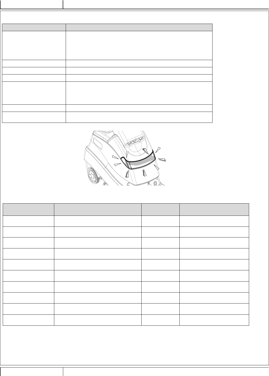
LED STATUS BAR OPERATION
Machine Action LED Response
• Manual Mode - Light Bar off (lights up white with blue on the sides only while scanning for a
location tag).
- Options include (see “Information Menu Display” to change)
“Always On” (white light)
“Always Off”
• Training Slow Flashing Green
• Autonomous Mode Slow Flashing Blue
• Machine Error Flashing Red
• Obstacle Detected Chasing Red or Orange (starting in center and moving to sides)
- Options include (see “Information Menu Display” to change)
Red
Orange
• Turning Side LEDs fl ash yellow
• Charging Batteries Light Bar will “fi ll” and advancing colors as follows (red, orange, yellow, green
and solid green) from discharged to fully charged see “Charging Batteries”.
FIGURE 3-9
SPEAKER OPERATION
Speaker Audible Alerts
Sound
Description Mode Sound Description
Horn Operator activates by pressing Horn Switch
(C).Manual Standard Horn
Reverse Slow beep when moving in reverse Manual Standard back-up alarm sound
Scan Successful Scan of location tag was successful Manual Two note ascending tone
Object Detection Alerts person to move out of way Autonomous Four beeps changing tone
repeating
Machine Error Machine stops, playback cannot continue Autonomous Longer low tone 3 seconds
repeating
Autonomous Operation Alerts person in area of scrubber (heartbeat)
Volume is adjustable between OFF, 1, 2, & 3. Autonomous Standard back-up alarm sound
Enter Recorded Plan
Start Area
Machine recognizes it is driving into the start
area of a plan Autonomous Two beeps higher tone
Leave Recorded Plan
Start Area
Machine recognizes it is driving out of the
start area of a plan Autonomous One beep lower tone
Plan Saved Successfully After training a plan, machine indicates plan
has been saved successfully Autonomous Three note ascending tone
Playback to Begin Alerts anyone in the area that machine is
about to start moving Autonomous Two second beep

12/2017 A - 43 56091197 - Nilfi sk Liberty SC50
ENGLISH - AINSTRUCTIONS FOR USE
9/2018
AFTER USE
1 When fi nished scrubbing, press the One-Touch Scrub Switch (M), this will automatically raise, retract and stop all the machine systems
(brush, squeegee, vacuum, solution and detergent). Drive the machine to a service area for daily maintenance and review of other needed
service upkeep.
2 To empty the solution tank;
• Solution tank only needs to be emptied if detergent was mixed in the tank and machine will not be used for a while.
• Drive the machine over a designated “DISPOSAL SITE” and open the Solution Drain Valve (8).
• The tank can also be drained by closing the Solution Shutoff Valve (34) and removing the cap from the Solution Filter (33), then open the
Solution Shutoff Valve to drain the solution out through the fi lter.
• Rinse the tank with clean water if detergent was used in the tank.
3 To empty the recovery tank;
• Pull the Recovery Tank Drain Hose (37) from its storage area.
• Direct the hose to a designated “DISPOSAL SITE” and unscrew the cap (hold the end of the hose above the water level in the tank to avoid
sudden, uncontrolled fl ow of waste water). The Recovery Tank Drain Hose can be squeezed to regulate the fl ow.
• Unlatch (36) and lift open the Recovery Tank Cover (20) set the prop rod (39).
• Empty and rinse the Debris Catch Tray (23) in the recovery tank.
• Thoroughly rinse the recovery tank with clean water.
• Inspect the squeegee and drain hoses; replace if kinked or damaged.
4 Remove the brush or pad holder. Rinse it in warm water and hang up to dry.
5 Remove the squeegee, rinse it with warm water and hang it up to dry. Inspect the squeegee blades for wear or tears.
6 Check the maintenance schedule below and perform any required maintenance before storage.
7 Store the machine indoors in a clean dry place. Keep from freezing. Leave the tanks open to help prevent odors.
8 Turn the machine off by pressing the Power Switch (B) and then remove the magnetic SmartKey.
9 Batteries are one of the most expensive replacement items on this machine. To protect your investment and to get as many cycles from the
batteries as possible, remember the following:
When installing batteries make certain the machine and charger are programed for the correct battery type.
Batteries will last longer if they are kept fully charged.
Batteries will prematurely fail if stored in a discharged state.
Battery chargers will not over or undercharge the batteries.
Every day after use, the battery charger must be plugged in and the charger must be allowed to run through a full charging sequence to
fully charge the batteries. This may take 8-12 hours depending on the battery status.
Always have the charger plugged into an AC outlet if the machine will not be used for a longer period of time to keep the battery(s)
charged.
MAINTENANCE
MAINTENANCE SCHEDULE
MAINTENANCE ITEM Daily Weekly Monthly Yearly
Charge Batteries X
Check/Clean Tanks & Hoses X
Check/Clean the Brushes/Pads X
Check/Clean the Squeegee X
Check/Clean Vacuum Motor Fan Inlet Screen (28) X
Empty/Clean Debris Catch Tray in Recovery Tank X
Clean 2D Safety Sensors (two) see “CLEAN SENSOR LENSES” X
Clean 3-D camera lenses see “CLEAN SENSOR LENSES” X
Clean Drop-Off sensors lenses see “CLEAN SENSOR LENSES” X
Clean 2-D Laser Scanner see “CLEAN SENSOR LENSES” X
Inspect Scrub Housing Skirt X
Inspect and clean Solution Filter X
Purge Detergent System X
Lubrication of Machine X
* Check Carbon Brushes X
* Have an Authorized Nilfi sk Service Center check the vacuum motor carbon motor brushes after 1200 operating hours (replace motor after 2000 recovery hours).
NOTE: Refer to the Service Manual for more detail on maintenance and service repairs.
A - 44 Nilfi sk Liberty SC50 - 56091197 12/2017
INSTRUCTIONS FOR USEA - ENGLISH 9/2018
AC
AA
AA
AA
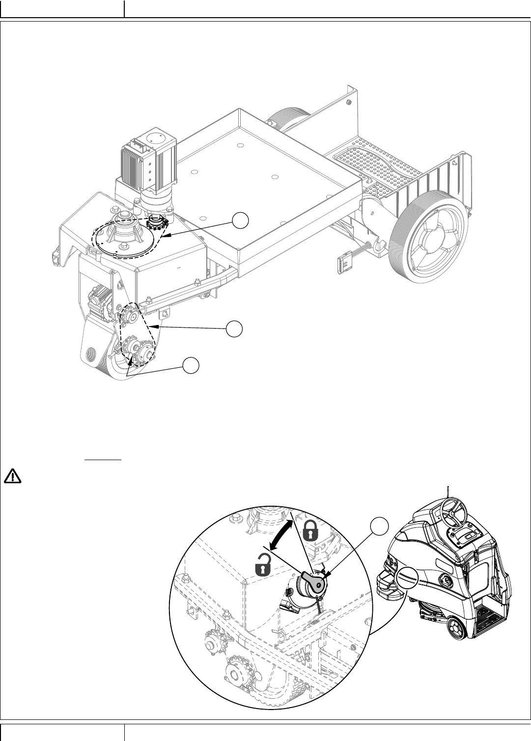
LUBRICATING THE MACHINE
Apply grease to (or grease fi tting locations) (AA):
Use grease type Lubriplate® 730-2 or equivalent
• Steering Chain
• Drive Wheel Chain
• Drive Chain Idler Sprocket (grease fi tting)
FIGURE 4-1
ELECTROMAGNETIC BRAKE
See Figure 4-2. The drive wheel motor has a built in electromagnetic brake that is engaged whenever the machine Power Switch (B) is OFF or
the Go Pedal (24) is not being pressed, machine in neutral. This brake can be manually overridden if necessary by reaching up around the back
of the front drive wheel and rotating the Brake Arm (AC) as shown. This should only be done in the event the machine needs to be pushed or
pulled. Remember to re-engage the brake arm after the machine is moved.
CAUTION!
Disconnect the batteries before
reaching into this area and rotating the
brake arm. Severe injury could occur if
steering components suddenly move.
IMPORTANT: The steering is controlled
electronically rather than by mechanical
linkage. This means that whenever the
power is off the machine cannot be steered
using the steering wheel.
FIGURE 4-2
12/2017 A - 45 56091197 - Nilfi sk Liberty SC50
ENGLISH - AINSTRUCTIONS FOR USE
9/2018
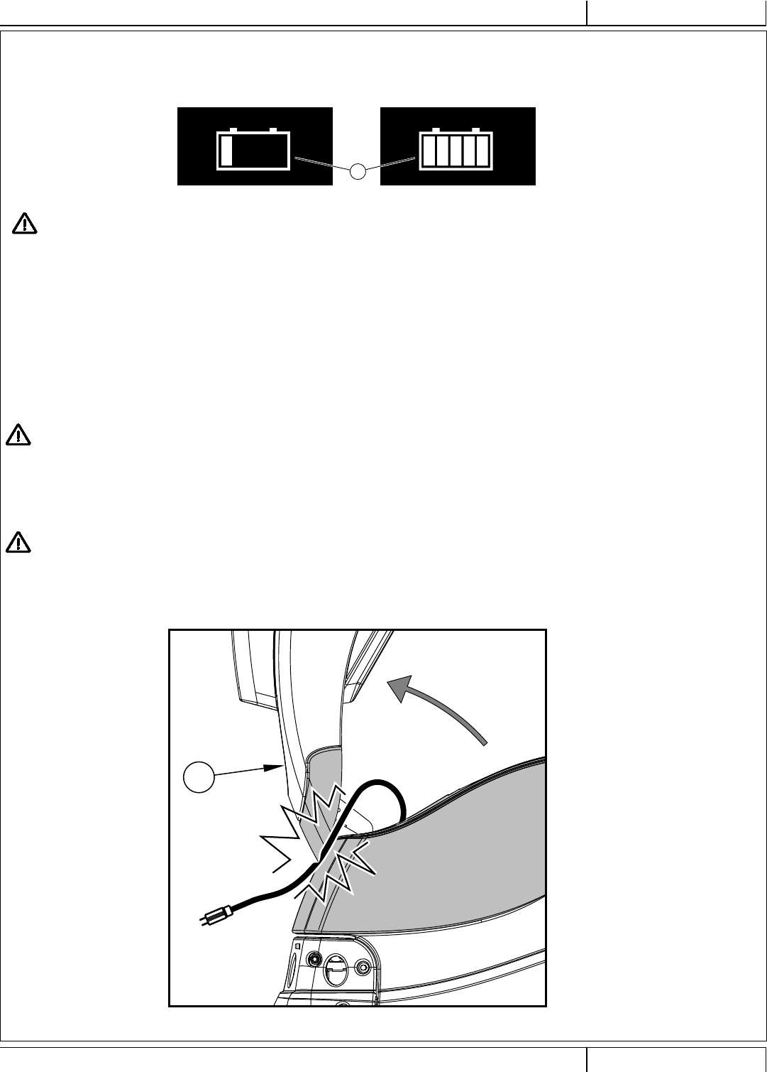
CHARGING GEL/AGM (VRLA) BATTERIES
Charge the batteries each time the machine is used or when the Battery Indicator (X3) is reading less than full.
X3
20
WARNING!
Charge batteries in a well-ventilated area. If battery acid makes contact with your skin, fl ush the affected area with water for 5
minutes and seek medical attention.
Do not smoke while servicing the batteries.
When Servicing Batteries...
* Remove all jewelry
* Do not smoke
* Wear safety glasses, rubber gloves and a rubber apron
* Work in a well-ventilated area
* Do not allow tools to touch more than one battery terminal at a time
* ALWAYS disconnect the negative (ground) cable fi rst when replacing batteries to prevent sparks.
* ALWAYS connect the negative cable last when installing batteries.
CAUTION!
Your valve regulated lead acid (VRLA) battery will deliver superior performance and life ONLY IF IT IS RECHARGED PROPERLY!
Under or overcharging will shorten battery life and limit performance. Be sure to FOLLOW PROPER CHARGING INSTRUCTIONS!
DO NOT ATTEMPT TO OPEN THIS BATTERY! If a VRLA battery is opened, it loses its pressure and the plates become oxygen
contaminated. THE WARRANTY WILL BE VOIDED IF THE BATTERY IS OPENED.
CAUTION!
When the Control Panel Housing (20) is opened it creates a pinch point between the LED lens and the solution tank. Do not route
the power cord through this area or the cord will be pinched and may be damaged.
A - 46 Nilfi sk Liberty SC50 - 56091197 12/2017
INSTRUCTIONS FOR USEA - ENGLISH 9/2018
CHARGING GEL/AGM (VRLA) BATTERIES - CONTINUED
The machine shipped with an onboard battery charger. To begin charging do the following:
1 Turn the machine off at the Power Switch (B).
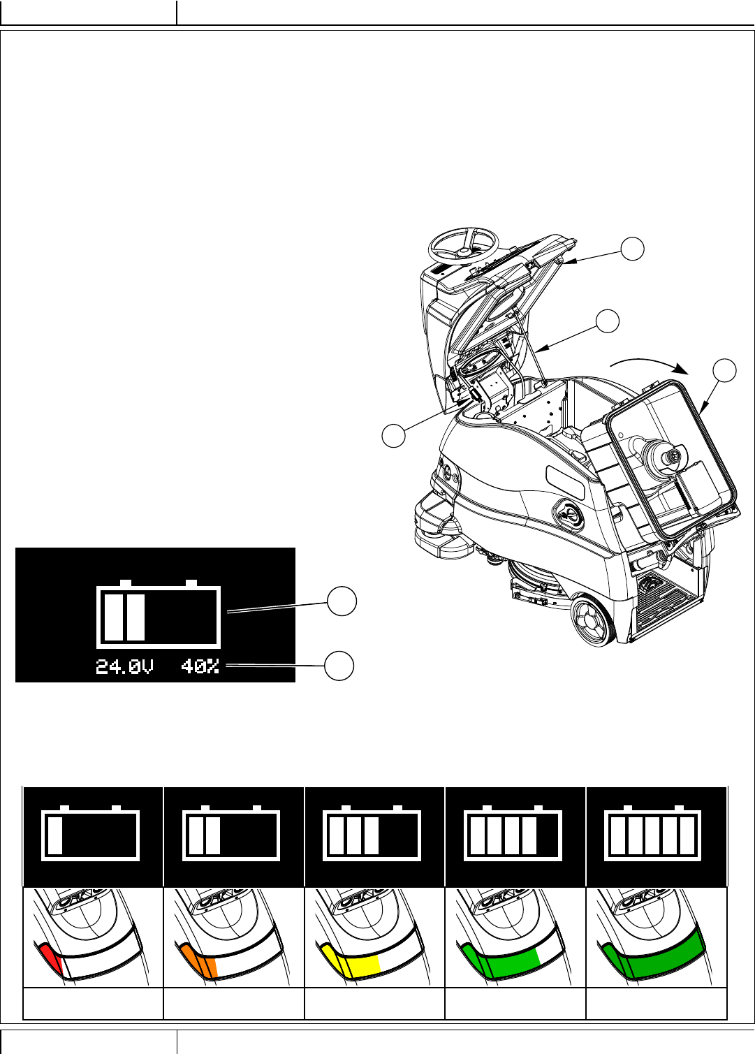
2 See Figures 4-3 & 4-4. Open the Control Panel Housing (20) set the Prop Rod (39).
3 Empty the Recovery Tank (22) using the Recovery Tank Drain Hose (37). Tip the Recovery Tank (22) back for proper ventilation using the Recovery Tank Lift
Handles (27).
4 Unwind the electrical cord for the onboard charger near the front of the machine and plug it into a properly grounded outlet. Refer to the OEM product
manual for more detailed operating instructions.
NOTE: While AC power is applied to the onboard charger all machine functions are disabled.
20
22
39
40
X3
X47
FIGURE 4-4
IMPORTANT: Make sure you have an appropriate charger for use on Gel cell batteries. Use only “voltage-regulated” or “voltage-limited” chargers.
Standard constant current or taper current chargers MUST NOT be used. A temperature-sensing charger is recommended, as manual adjustments are
never accurate and will damage any VRLA battery.
FIGURE 4-3
5 The Battery Charge Status Indicator (X3) will begin showing the
batteries’ state of charge. This indicates that the charging cycle has
begun. As the charging cycle continues, the battery charge level will
fi ll in. Each of the fi ve bars within the icon will fl ash and then become
solid until all of the fi ve bars are lit solid. The Display (X) will also
show battery voltage and percent of charge (X47).
6 The LED status bar (4) will also display the state of charge, using
advancing colors from red to green see Figure 4-5.
7 When the Battery Charge Status Indicator (X3) is completely fi lled
and status bar is solid green, the machine senses fully charged
batteries, however the charging process may not be complete. Rely
on the status lights on the Charger (31) (and its OEM manual) to
verify when the batteries are completely charged. This may take
several hours depending upon the condition of the batteries before
charging.
8 After charging is complete unplug the charger and wind up the Cord
(40). Wait at least 10 seconds before turning on the machine after
unplugging the charger.
FIGURE 4-5
Advancing
Red
Advancing
Orange
Advancing
Yellow
Advancing
Green
Solid
Green
12/2017 A - 47 56091197 - Nilfi sk Liberty SC50
ENGLISH - AINSTRUCTIONS FOR USE
9/2018
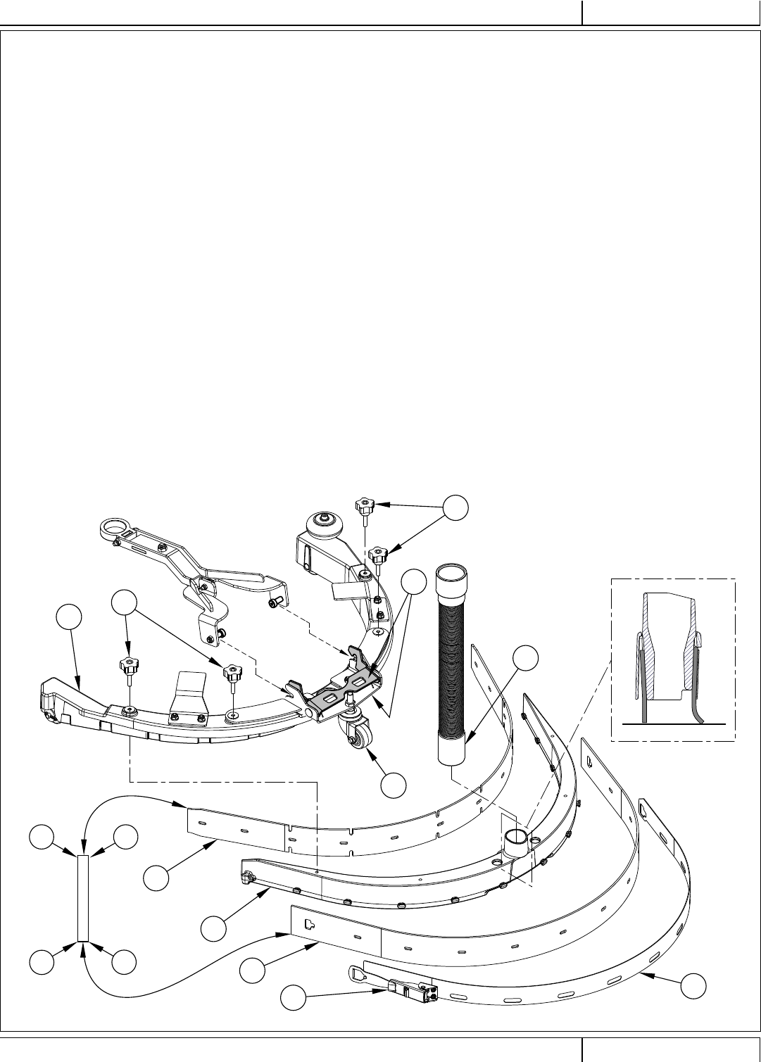
SQUEEGEE MAINTENANCE
If the squeegee leaves narrow streaks or water, the blades may be dirty or damaged. Remove the squeegee, rinse it under warm water and inspect the blades.
Reverse/fl ip or replace the blades if they are cut, torn, wavy or worn.
To Reverse or Replace the Rear Squeegee Wiping Blade...
1 See Figure 4-5. Raise the deck and squeegee assembly off the fl oor, then unsnap the Rear Squeegee Blade Removal Latch (23).
2 Remove the Tension Strap (AA).
3 Slip the rear blade (AB) off the alignment pins.
4 The squeegee blade has 4 working edges. Turn the blade so a clean, undamaged edge points toward the front of the machine. Replace the blade if all 4
edges are nicked, torn or worn to a large radius.
5 Install the blade, following the steps in reverse order and adjust the squeegee tilt if necessary.
To Reverse or Replace the Front Squeegee Blade...
1 Raise the squeegee off the fl oor, then rotate the squeegee towards the outside of the machine to access. Disconnect the squeegee hose (AD) from the
squeegee. Squeeze the back of the Squeegee Mount Bracket (AE) to open the bracket and pull the squeegee assembly off the machine.
2 Loosen the four Squeegee Cover Knobs (11). Then lift the Squeegee Cover (AF) off of the Squeegee Casting (AG).
3 Slip the front blade (AH) off the alignment pins.
4 The squeegee blade has 4 working edges. Turn the blade so a clean, undamaged edge points toward the front of the machine. Replace the blade if all 4
edges are nicked, torn or worn to a large radius.
5 Install the blade, following the steps in reverse order and adjust the squeegee tilt if necessary.
SQUEEGEE ADJUSTMENT
There is only one squeegee assembly adjustment possible, tilt.
Adjust the squeegee tilt if the squeegee is not wiping the fl oor dry.
1 Park the machine on a fl at, even surface and lower the squeegee. Then drive the machine forward enough to have the squeegee blades fold over to the
rear.
2 Adjust the squeegee tilt using the Rear Caster Wheel (AC) so that the rear squeegee blade touches the fl oor evenly across its entire width and is bent over
slightly as shown in the squeegee cross section (AI).
FIGURE 4-5
AI
1 2
3
4
11
11
23 AA
AB
AC
AD
AE
AF
AG
AH

A - 48 Nilfi sk Liberty SC50 - 56091197 12/2017
INSTRUCTIONS FOR USEA - ENGLISH 9/2018
AA2
AA1
AA3
REMOTE BATTERY REPLACEMENT
The remote’s battery has an expected life of 6 to 8 months, assuming normal usage. More frequent operation will shorten battery life. Replacement battery is type
CR2430.
1 See Figures 4-6 & 4-7. Slide the Protective Cover (AA3) off of Remote (AA1) to expose Battery Cover (AA2).
2 See Figures 4-8 & 4-9. Insert the tip of a tweezers or small screwdriver (AA4) between battery cover (AA2) and Remote body (AA1), and begin to pry open
battery cover.
3 See Figure 4-10. Fully raise the battery cover (AA2) from the body of the remote then remove the battery cover.
4 See Figure 4-11. Using the tip of a tweezers or blade screwdriver (AA4) carefully start to slide the Battery (AA5) out of the remote. Grasp the battery and
pull it out of the remote. Discard the battery according to local requirements.
5 Install the new battery by following the previous steps in reverse order. Check the battery polarity for correct orientation before insertion.
AA1
AA3
AA2
AA1
AA4
AA2
AA1
AA2
AA1
AA5
AA4
AA1
FIGURE 4-6 FIGURE 4-7
FIGURE 4-8 FIGURE 4-9
FIGURE 4-10 FIGURE 4-11
12/2017 A - 49 56091197 - Nilfi sk Liberty SC50
ENGLISH - AINSTRUCTIONS FOR USE
9/2018
TROUBLESHOOTING
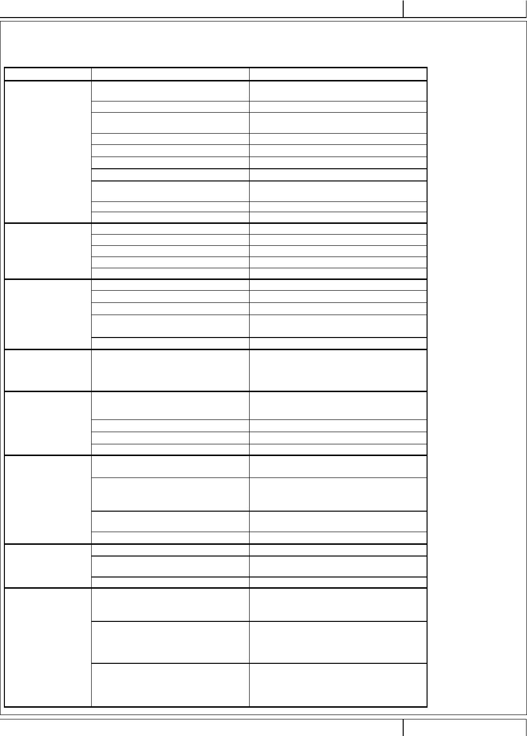
GENERAL MACHINE TROUBLESHOOTING
Problem Possible Cause Remedy
Poor water pick-up
Vacuum hose not connected to the squeegee
assembly Connect vacuum hose to squeegee assembly
Worn or torn squeegee blades Reverse or replace
Squeegee out of adjustment Adjust so blades touch fl oor evenly
across entire width
Recovery tank full Empty recovery tank
Recovery Tank Drain Hose (37) leak Secure drain hose cap or replace
Recovery Tank Cover (20) gasket leak Replace gasket / Seat cover properly
Debris caught in Squeegee (11) Clean squeegee assembly
Recovery Hose between squeegee and
recovery tank clogged Remove debris
Using too much solution Reduce fl ow via control panel solution switch
Vacuum set to quiet mode Set vacuum to high
Poor scrubbing
performance
Worn brush or pad Replace brush or pad
Wrong brush or pad type Consult Nilfi sk
Wrong cleaning detergent Consult Nilfi sk
Moving machine too fast Slow down
Not using enough solution Increase solution fl ow
Inadequate or no
solution fl ow
Solution tank empty Fill solution tank
Solution lines, valves or fi lter (33) clogged Flush lines and clean solution fi lter
Solution Shutoff Valve (34) closed Open solution shutoff valve
Solution Solenoid Valve (32) plugged or
defective Clean or replace valve
Solution pump air locked (contact Nilfi sk Authorized Service Center)
Solution tank empty
Indicator (X23) appears
when there is solution
in the tank
Solution sensor failed (contact Nilfi sk Authorized Service Center)
Machine does not
power ON
Machine Battery Connector (43) disconnected Reconnect battery connectors
Tripped 5 Amp circuit breaker (E) Check for electrical short circuit & reset
Blown Main Fuse 100 Amp (42) Replace Main Fuse 100 Amp
Charger Interlock engaged Unplug Charger
No FWD/REV wheel
drive
A direction has not been selected Press (Q) to select Forward direction or press (R) to
select Reverse direction.
Emergency Stop Switch (D) activated, display
will show Emergency Stop Activated Indicator
(X18)
Reset the Emergency Stop Switch
Drive system speed controller Check error fault codes
(contact Nilfi sk Authorized Service Center)
Tripped 50 Amp circuit breaker (D) Check for drive motor overload
No Detergent Flow
Empty Detergent Cartridge (3) Fill detergent cartridge
Plugged or kinked detergent fl ow line Purge system, straighten lines to
remove any kinks
Detergent pump Check pump, wiring and lines
Magnetic SmartKey
Errors
No Key Indicator (X19).
-No Magnetic SmartKey is present on the
SmartKey Reader (A).
Place an appropriate SmartKey onto the SmartKey
Reader.
Key Read Error Indicator (X20).
- Magnetic SmartKey present on the
SmartKey Reader (A) cannot be read.
Clean both the SmartKey and the SmartKey
Reader using a clean cloth. Depress the SmartKey
between your thumb and forefi nger to insure free
movement of the magnet.
Restricted User Key Indicator (X21).
-Magnetic SmartKey present on the SmartKey
Reader (A) is not programmed to be used
with this machine.
Place a SmartKey that has been programmed to be
used with this machine onto the SmartKey Reader.
A - 50 Nilfi sk Liberty SC50 - 56091197 12/2017
INSTRUCTIONS FOR USEA - ENGLISH 9/2018
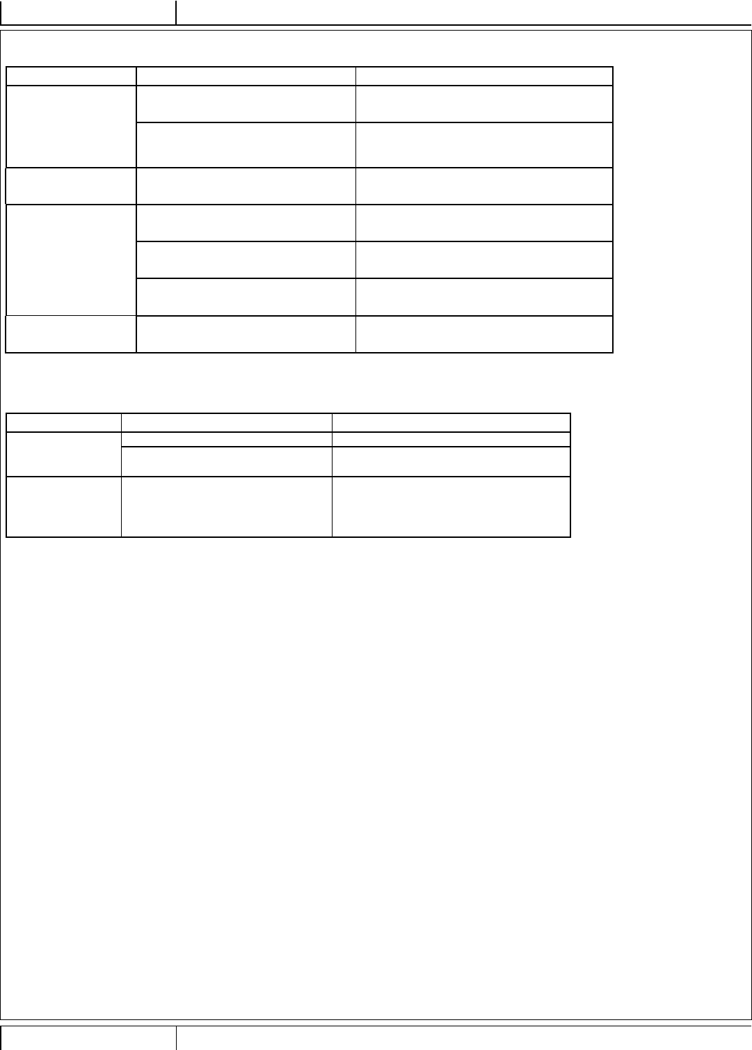
AUTONOMOUS MODE TROUBLESHOOTING
Problem Possible Cause Remedy
Machine driving erratic
(stopping frequently
when there is no
obstacle) or not driving
Dirty lenses Clean all of the sensor lenses (see “Clean Sensor
Lenses”)
Scratched lens
Severe scratch may require component (sensor)
replacement
(contact Nilfi sk Authorized Service Center)
Machine will not train
a plan Home position has not been set Move machine to a Location Tag and Set Home
Position
Machine will not
playback a plan
Machine not within a start area Drive machine to the start area of a plan (audible cue
of two beeps upon entering start area)
Battery charge too low to complete plan Fully charge the batteries
Environment has changed too much so that
machine cannot locate itself on its map Delete the tag, rescan the tag, retrain the plan
Plan playback not as
expected Machine
REMOTE TROUBLESHOOTING
Problem Possible Cause Remedy
Remote does not
fl ash LEDs and beep
upon machine startup
Remote not paired to the machine Contact Nilfi sk to pair the remote to the machine
Batteries are worn-out/discharged Replace/recharge remote batteries
Remote does not
light any LEDs after
pressing the status
request button (AB)
Remote is out-of-range of the machine Move the remote closer to the machine
12/2017 A - 51 56091197 - Nilfi sk Liberty SC50
ENGLISH - AINSTRUCTIONS FOR USE
9/2018
FAULT CODE DISPLAY
Fault Code Description
A2 Power Module Faults - continued
2-031 M1 Output Overload Warning
2-032 M2 Output Overload Warning
2-033 M3 Output Overload Warning
2-034 M4 Output Overload Warning
2-035 M5 Output Overload Warning
2-036 Actuator 1 Output Overload
2-037 M7 Deck Actuator Output Overload
2-038 Actuator 3 Output Overload
2-041 M1 Output Overcurrent
2-042 M2 Output Overcurrent
2-045 M5 Output Overcurrent
2-046 Actuator 1 Output Overcurrent
2-047 M7 Deck Actuator Output Overcurrent
2-048 Actuator 3 Output Overcurrent
2-051 M1 Output Short
2-052 M2 Output Short
2-053 M3 Output Short
2-054 M4 Output Short
2-055 M5 Output Shorted
2-056 Actuator 1 Output Short
2-057 M7 Deck Actuator Output Shorted
2-058 Actuator 3 Output Short
2-061 M1 Output Current Sensor Fault
2-062 M2 Output Current Sensor Fault
2-063 M3 Output Current Sensor Fault
2-064 M4 Output Current Sensor Fault
2-065 M5 Output Current Sensor Fault
2-066 Over Temperature Cutoff
2-067 Under Temperature Cutoff
2-071 M1 Output Overload Timeout
2-072 M2 Output Overload Timeout
2-073 M3 Output Overload Trip
2-074 M4 Output Overload Trip
2-075 M5 Output Overload Timeout
2-076 Actuator 1 Output Stall Fault
2-077 M7 Deck Actuator Output Stall
2-078 Actuator 3 Output Stall Fault
2-081 EEPROM Fault
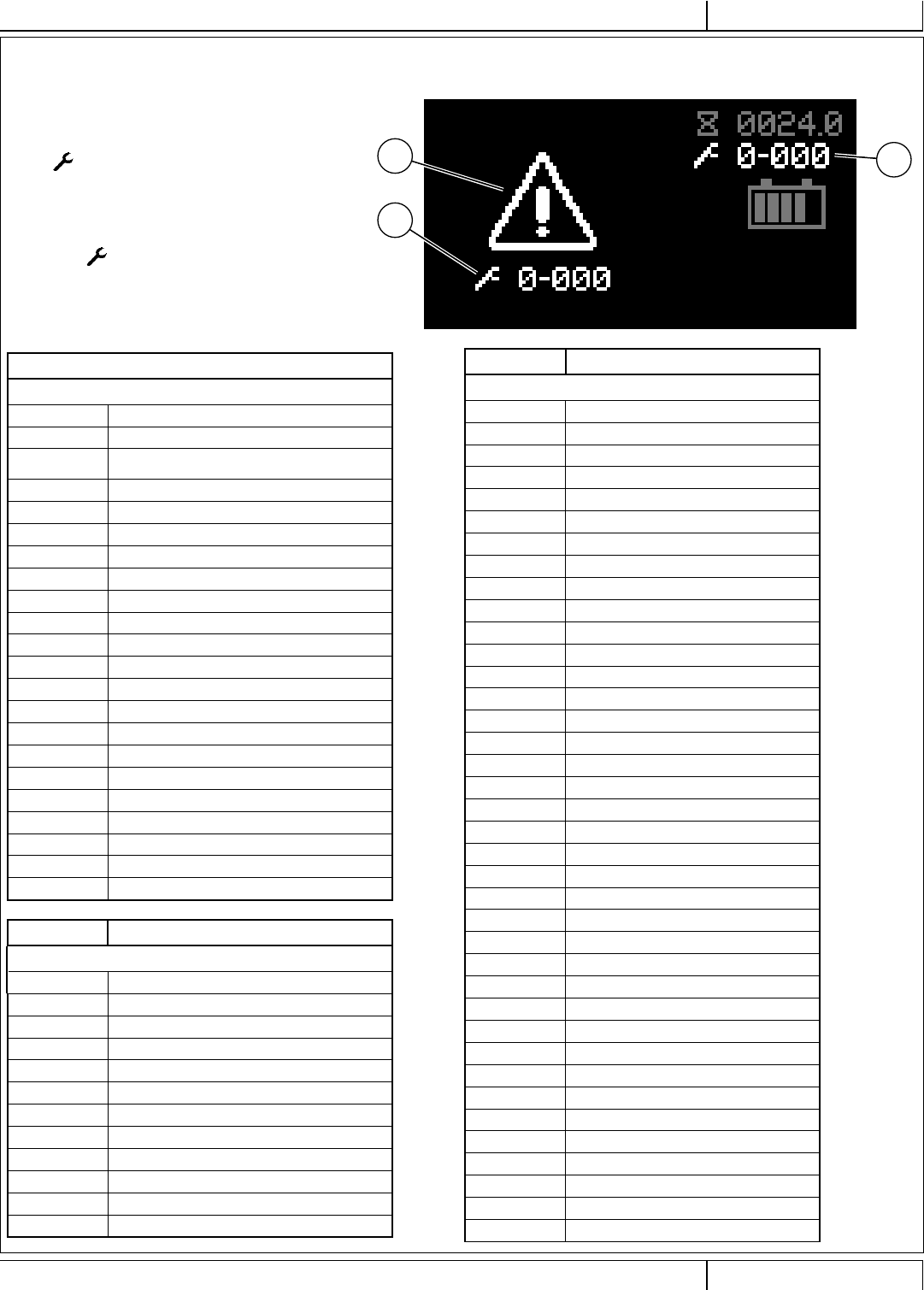
Any fault codes detected by the controllers will be displayed on
the control panel display as they occur. If more than one fault
exists, the display will sequence through the fault codes at one-
second intervals. The fault will display as a mechanical wrench
symbol followed by a four-digit code.
Fault codes are displayed as X-YYY, where
X = system number (1: main board, 2: power module, 3: drive
controller, 5: autonomous platform)
YYY = fault code number
For example, 1-101 would be M10 solution pump – short.
X2 Active Fault Code
X14 Critical Fault Indicator
X15 Fault Code (Critical)
Fault Code Description
A1 Main Controller Faults
1-001 K1 Key Switch Input (KSI) Relay Coil Open
1-002 K1 Key Switch Input (KSI) Relay Coil Shorted
1-003 K1 Key Switch Input (KSI) Relay Contact
Welded
1-010 CAN Bus 0
1-011 CAN Bus 1
1-101 M11 Solution Pump Shorted
1-102 L2 Solution Solenoid Shorted
1-106 M6 Detergent Pump Shorted
1-201 M2 Scrub Motor Overload
1-202 M5 Vacuum Motor Overload
1-301 M1 Drive Wheel Motor Overload
1-560 EEPROM Confi guration Fault
1-561 EEPROM Options Fault
1-562 EEPROM Sys Values Fault
1-563 EEPROM Fault Log Fault
1-564 EEPROM User Key List Fault
1-565 EEPROM Impact Log Fault
1-901 Steering Controller packet loss:
1-902 Drive controller packet loss:
1-903 Steering queue congestion
1-904 Drive queue congestion
1-905 Autonomy spamming: Command Over-run
Fault Code Description
A2 Power Module Faults
2-011 Power Supply Fault
2-012 K2 Power Module Contactor Coil Overload
2-013 K2 Power Module Contactor Contacts Welded
2-014 K2 Power Module Contactor Coil Open
2-017 Overvoltage Cutoff
2-018 Undervoltage Cutoff
2-021 M1 Output Open
2-022 M2 Output Open
2-025 M5 Output Open
2-026 Actuator 1 Output Open
2-027 M7 Actuator Output Open
2-028 Actuator 3 Output Open
X2
X15
X14
A - 52 Nilfi sk Liberty SC50 - 56091197 12/2017
INSTRUCTIONS FOR USEA - ENGLISH 9/2018
FAULT CODE DISPLAY - CONTINUED
Fault Code Description
A2 Power Module Faults - continued
2-082 PDO Timeout Fault
2-083 CAN Bus Fault
2-084 Internal Communication Timeout
2-086 Over Temperature Cutback
2-087 Under Temperature Cutback
2-088 K2 Power Module Contactor Coil Open
2-091 M1 Output Hardware Fault
2-092 M2 Output Hardware Fault
2-093 M3 Output Hardware Fault
2-094 M4 Output Hardware Fault
2-095 M5 Output Hardware Fault
2-096 Parameter Change Fault
2-097 Actuator 1 Output Current Sensor Fault
2-098 M7 Actuator Output Current Sensor
2-101 Actuator 3 Output Current Sensor Fault
2-102 Temperature Sensor Fault
2-103 K2 Power Module Contactor Coil Short
Fault Code Description
A3 Drive Controller Faults
3-001 Excessive M1 Drive Wheel Motor Current
3-002 Internal Clock Failure
3-009 Internal A3 Drive Wheel Controller Fault
3-010 Driver 1 or Driver 2 Overcurrent
3-011 K3 Drive Wheel Contactor Coil Open
3-012 Emergency Reverse Redundancy
3-013 A3 Drive Wheel Controller EEPROM Fault
3-015 K3 Drive Wheel Contactor Contact Not Closing
3-016 M1 or M2 Drive Wheel Motor Outputs Shorted
3-017 K3 Drive Wheel Contactor Contact Stuck Closed
3-019 Lost Communication with A1 Main Machine
Controller (MMC)
3-020 Internal A3 Drive Wheel Controller Fault
3-021 Internal A3 Drive Wheel Controller Fault
3-022 Go Pedal (POT 1) Supervisor Fault
3-023 R1 Speed Limit Potentiometer Supervisor Fault
3-024 Supervisor Pot3 Fault
3-025 5V Output Supervisor Fault
3-026 S1 Operator Presence Swich (OPS) Input
Supervisor Fault
3-027 Steering System Ready Input (Switch 2)
Supervisor Fault
3-028 S2 Emergency Stop Switch Input (Switch 3)
Supervisor Fault
3-029 Autonomous System Okay Input (Switch 4)
Supervisor Fault
3-030 Supervisor Sw5 Fault
3-031 Key Switch Input (KSI) Supervisor Fault
3-032 Supervisor Motor Speed Fault
3-033 Controller Check Fault
Fault Code Description
A3 Drive Controller Faults- continued
3-034 External Supply Fault
3-036 Y1 Emergency Brake Coil Open
3-037 Y1 Emergency Brake Coil Driver On
3-041 Go Pedal Switch Input
3-042 Speed Limit Input
3-043 Pot 3 Fault
3-050 Very Low Voltage
3-052 Very Low Controller Temperature
3-053 Very High Controller Temperature
3-054 Low Battery Positive (B+) Power Input
3-070 K3 Drive Wheel Contactor Shorted or Y1
Emergency Brake Coil Shorted
3-071 Driver 3 Fault
3-072 Driver3 Overcurrent
3-073 Driver4 Fault
3-074 Driver4 Overcurrent
3-075 Driver5 Fault
3-076 Driver5 Overcurrent
3-077 Driver6 Fault
3-078 Driver6 Overcurrent
3-079 Correlation Fault
3-080 Go Pedal Switch Closed At Power On
3-081 Parameter Change
3-082 Internal A3 Drive Wheel Controller Fault
3-090 A3 Drive Wheel Motor Temperature Hot Cutback
3-092 M1 Drive Wheel Motor Circuit Open
3-093 M1 Drive Wheel Motor Short
3-094 High Voltage
3-095 A3 Wheel Drive Controller Temperature Is Low
3-096 Stall Detected
3-097 A3 Wheel Drive Controller Temperature Is High
3-098 High Voltage
3-099 Low Voltage
3-101 User Fault Estop
3-102 User Fault Severe
12/2017 A - 53 56091197 - Nilfi sk Liberty SC50
ENGLISH - AINSTRUCTIONS FOR USE
9/2018
Fault Code Description
A4 Steering Controller Faults
4-000 A4 Timeout
4-001 Low Voltage
4-002 Intermediate stage under voltage
4-004 Controller, High Temperature
4-006 Controller Failure, Power Stage
4-007 Excessive Voltage
4-009 5V Output Fault
4-010 12V Output Fault
4-014 CAN Message Error
4-015 Controller Error, Checksum
4-016 Controller Error, Initialization
4-021 Very High Motor Current
4-022 Voltage at J5-12
4-023 Encoder Error
4-024 Open Stator Winding
4-025 High Controller Temperature
4-026 High Motor Current
4-027 Input Sum Failure
4-028 Insuffi cient Input Difference
4-029 Steering Angle Input Matches J5-5
4-030 J5-5 Input Voltage Abnormal
4-031 Steering Angle Input Abnormal
Fault Code Description
A5 Autonomous Platform Controller Faults
5-4060 E5 Low Temp
5-4061 E5 High Temp
5-F040 E5 Power Idle
5-F041 E5 Power Key
5-F042 E5 Power K Board
5-F043 E5 Power C Board
5-F344 E5 Power Temp
5-F345 E5 Power Voltage
5-F246 E5 No Laser Acknowledge
5-F640 E5 Unknown Free Space on SD Card
5-F641 E5 No Space on SD Card
5-F642 A5 Failed to Delete Log File
5-F270 A5 Platform has lost Communication with Compute
Board
5-F271 A5 Platform has lost Communication with CAN server
5-F652 A5 No Forward Plan without Collisions
5-F650 A5 No Valid 3D Data from Camera
5-F653 A5 Brush Height Not Responding
5-F651 A5 No Valid Laser Scan Data
5-F660 A5 Could Not Load Plan from Database
5-F470 A5 User Cancelled Training
5-F671 A5 Save Plan Failed
5-F672 A5 Save State Timed Out
5-F661 A5 Failed to Generate or Load Plan
5-F673 A5 Failed when Ending Training
5-F454 A5 Lost
5-F455 A5 Outside Safe Zone
5-F456 A5 Internal Plan Problem
5-F474 A5 Can’t Train, No Home Position
5-F475 A5 Can’t Train, Lost
5-F476 A5 Can’t Train, Busy
5-F643 A5 Save Log Error
5-F444 A5 Log Upload Busy
5-F445 A5 Log Upload Fail
5-F677 A5 Train Cancel Fail
5-F657 A5 Bad Traction
5-F658 A5 Autonomy Exit
5-F45D A5 Person On Board
5-F559 A5 Bad Exit
5-F45A A5 Camera Block
5-F45B A5 Laser Block
5-F45C A5 C&L Block
5-F45E A5 Out Of Memory
5-F646 A5 Log Clear Fail
5-F478 A5 Near Dropoff
FAULT CODE DISPLAY - CONTINUED
A - 54 Nilfi sk Liberty SC50 - 56091197 12/2017
INSTRUCTIONS FOR USEA - ENGLISH 9/2018
FAULT CODE DISPLAY - CONTINUED
Fault Code Description
A6 Platform Controller Faults
6-0000 A6 Timeout (no can bus heartbeat)
6-3000 A6 Low Battery Voltage
6-3001 A6 High Battery Voltage
6-3010 A6 Low 1.8 Voltage
6-3011 A6 High 1.8 Voltage
6-3020 A6 Low 3.3 Voltage
6-3021 A6 High 3.3 Voltage
6-3030 A6 Low 5.0 Voltage
6-3031 A6 High 5.0 Voltage
6-FB00 A6 ILOK Boot
6-FB01 A6 ILOK Off
6-FB10 A6 Health
6-F400 A6 Wrong Port
6-F401 A6 Hwack
6-F402 A6 Swack
6-F510 A6 Boot Error
6-F511 A6 Boot Image
6-F612 A6 Boot Timeout
6-F513 A6 Laser Calibration
6-F514 A6 Camera Calibration
6-F515 A6 Dropoff Calibration
6-F421 A6 Set Home Position Successful
6-F422 A6 No Home Position
6-F623 A6 Permanently Lost
6-FC00 A6 Main Board Fault
6-FC01 A6 Unknown Main Fault
6-F530 A6 Update Not Ready
6-F431 A6 Update: No Connection
6-F632 A6 Update Timeout
6-F433 A6 Bad Update Download
6-F634 A6 Bad Update Install
6-F424 A6 Unknown Location Tag
6-F616 A6 Bad Mapping State
6-F617 A6 Persistence Database is Corrupt
6-F618 A6 File Access Problem with Database
6-F510 A6 Compute Box Boot Failure
6-F619 A6 Inconsistent Boot Image
6-F480 A6 Failed to Set QR Code to File
6-F790 A6 Exception
6-F591 A6 Error Deleting File
Fault Code Description
A6 Platform Controller Faults-continued
6-F692 A6 Bad Command
6-F693 A6 Bad Object
6-F694 A6 No Data for SDO
6-F695 A6 Received another SDO before Finishing
6-F696 A6 Wrong Toggle Bit
6-F4A0 A6 No Laser Pulse
6-F427 A6 Unsaved loc. Tag
6-F4A0 A6 Bad Laser Calib.
6-F4A1 A6 Bad Camera Calib
6-F4A2 A6 Bad Dropoff Calib.
6-F4A3 A6 Calib. Cancelled
6-F4A4 A6 Calib. Error
6-F625 A6 Orphaned Plan
6-F426 A6 Tag Already Saved
6-F61A A6 Old Platform Box
6-F61B A6 No Platform Ver.
6-F4B1 A6 Out of Memory
6-F41C A6 No Platform S/W
6-FE10 A6 Mode Out Of Range
6-FE11 A6 Manual Fail
6-FE12 A6 Copycat Fail
6-FE13 A6 Fill-in Fail
6-FE14 A6 Autoscrub Fail
6-F61D A6 Boot Timeout
6-F6C0 A6 Moving Backward
6-F6C1 A6 Bad Battery
6-F6C2 A6 Bad Confi g
6-F6CC A6 Platform Comm.
6-F6CD A6 Overspeed
6-F6CE A6 Bad Wheel Enc.
6-F6CF A6 High Speed Turn
6-F5C3 A6 Dropoff Error
6-F4C4 A6 L Front Dropoff
6-F4C5 A6 R Front Dropoff
6-F4C6 A6 L Side Dropoff
6-F4C7 A6 R Side Dropoff
6-F4C8 A6 Prox. Error
6-F4C9 A6 Front Prox. Err.
6-F4CA A6 Left Prox. Err.
6-F4CB A6 Right Prox. Err.
6-F6D0 A6 Plan Failed
6-F5B2 A6 SD Card Fail
6-F4B3 A6 Degraded
12/2017 A - 55 56091197 - Nilfi sk Liberty SC50
ENGLISH - AINSTRUCTIONS FOR USE
9/2018
FAULT CODE DISPLAY – CONTINUED
Fault Code Description
G1 Battery Charger Faults
8-0000 G1 Timeout
8-F001 F-0-0-1 DC-DC failure: LLC excessive leakage fault
8-F002 F-0-0-2 PFC failure: PFC excessive leakage fault
8-F003 F-0-0-3 PFC has taken too long to boost
8-F004 F-0-0-4 The charger has been unable to calibrate the
current offset
8-F005 F-0-0-5 The voltage drop across the DC relay is too
high while the relay is closed.
8-E001 E-0-0-1 Battery voltage over limit in software.
Typically 2.5V/cell.
8-E002 E-0-0-2 Battery voltage too low to start a charge
cycle. Algorithm dependent – typically 0.1V/cell.
8-E003 E-0-0-3 Charge time limit reached.
Algorithm dependent.
8-E004
E-0-0-4 Battery could not be trickle charged up to
the minimum voltage. May also be used for other
battery-related errors depending on the algorithm.
8-E007 E-0-0-7 Charge amp-hour Limit reached.
Algorithm dependent.
8-E008 E-0-0-8 Battery temperature out of range.
Algorithm dependent.
8-E012 E-0-1-2 Reverse polarity
8-E013 E-0-1-3 Battery does not take current
8-E020 E-0-2-0 No active algorithm selected
8-E021 E-0-2-1 High battery voltage while charging.
Algorithm dependent – typically 2.8V/cell
8-E022 E-0-2-2 Low battery voltage while charging.
Algorithm dependent – typically 0.1V/cell
8-E023 E-0-2-3 High AC voltage error (>270VAC)
8-E024 E-0-2-4 Charger failed to turn on properly
8-E025 E-0-2-5 AC voltage has dipped below 80VAC 3 times
in 30 seconds
8-E028 E-0-2-8 Attempt to select algorithm incompatible with
this software
8-E029 E-0-2-9 Cannot transmit on CAN bus
8-E030 E-0-3-0 CAN-1 heartbeat timeout on Battery module
8-E031 E-0-3-1 The Vref for the ADC measurements has
triggered an alarm
Fault Code Description
G1 Battery Charger Faults-continued
8-E032 E-0-3-0 CAN-2 heartbeat timeout on Battery module
8-E036 E-0-3-6 Battery temperature sensor is missing or
shorted
8-E037 E-0-3-7 CAN Open reprogramming failed
8-E038 E-0-3-8 Fan will not turn
8-E040 E-0-4-0 Fan voltage pulled low
8-0098 General USB Fault
8-0099 Unknown Fault
A - 56 Nilfi sk Liberty SC50 - 56091197 12/2017
INSTRUCTIONS FOR USEA - ENGLISH 9/2018
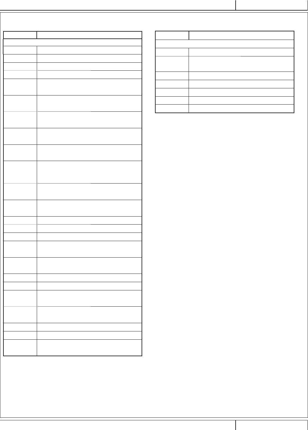
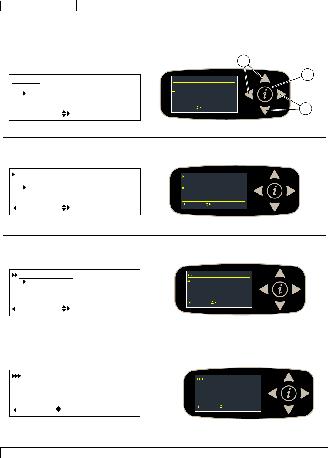
FAULT CODE HISTORY
Every fault code that occurs is recorded by the machine and kept in a history log. See Figures 5-1 – 5-4. To view the fault history press the
Information Switch (Y) to bring up the information menu. Use the four Navigation Arrows (Y1) (up, down, left & right) to move through the menu
and the information switch to exit the menu.
Y
Menu
Hours
Faults
Keys
Options
iExit Select Y1
Y1
Faults
Active Faults 0
Fault History 5
Back Select
Fault History
1-003 0007.7
Back Select
(1/5)
3-001 0005.2
3-001 0005.2
3-001 0004.3
Fault History
1-003 0007.7
Back Scroll
(1/5)
K1 Contact Weld
Scroll down to Faults, right arrow to select.
Menu [Menu] ________________________________
Hours [Hours]
Faults [Faults]
Keys [Keys]
Options [Options] _______________________
Exit [i Exit] Select [Select]
Scroll down to Fault History, right arrow to select.
Faults [Faults] ______________________________
Active Faults [Active Faults]
Fault History [Fault History]
___________________________________________
Back [Back] Select [Select]
A list of all faults and corresponding timestamp will be displayed, scroll
up or down to an individual fault, right arrow for more information.
Fault History [Fault History] __________________
Fault code Drive Hours
___________________________________________
Back [Back] Select [Select]
The fault is displayed along with the timestamp and description. Use the
up and down arrows to scroll through the list of faults.
Fault History [Fault History] _________________
Fault Code Drive Hours
Fault Code Description
___________________________________________
Back [Back] Scroll [Scroll]
FIGURE 5-1
FIGURE 5-2
FIGURE 5-3
FIGURE 5-4
12/2017 A - 57 56091197 - Nilfi sk Liberty SC50
ENGLISH - AINSTRUCTIONS FOR USE
9/2018
SPECIFICATIONS
ACCESSORIES / OPTIONS
In addition to the standard components, the machine can be equipped with the following accessories/options, according to the machine specifi c use:
Disc Machines REV Machines
• Brushes with harder or softer bristles • Pads with more or less abrasiveness
• Pads with more or less abrasiveness • SPP pads for fi nish removal
For further information about the above-mentioned accessories, contact an authorized Retailer.
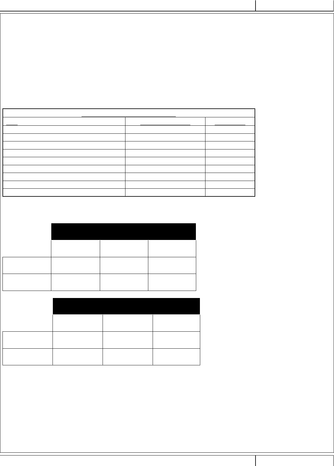
MATERIAL COMPOSITION AND RECYCLABILITY
Material Composition and Recyclability
Type % of machine weight % recyclable
Aluminum 1% 100%
Electrical / motors / engines - misc. 24% 80%
Ferrous metals 35% 100%
Harnesses / cables 2% 90%
Liquids 0% 0%
Plastic - non-recyclable 1% 0%
Plastic - recyclable 8% 100%
Polyethylene 26% 100%
Rubber 3% 100%
SOLUTION FLOW RATES
Manual Mode Flow Rates
At Full Manual Speed*
1 bar 2 bars 3 bars
20” Disc 0.16 GPM /
0.6 liters/minute
0.35 GPM /
1.3 liters/minute
0.50 GPM /
1.9 liters/minute
20” REV 0.13 GPM /
0.5 liters/minute
0.18 GPM /
0.7 liters/minute
0.23 GPM /
0.9 liters/minute
Autonomous
Mode
Flow Rates
At Full Autonomous Speed*
1 bar 2 bars 3 bars
20” Disc 0.11 GPM /
0.4 liters/minute
0.23 GPM /
0.9 liters/minute
0.33 GPM /
1.3 liters/minute
20” REV 0.09 GPM /
0.3 liters/minute
0.12 GPM /
0.5 liters/minute
0.15 GPM /
0.6 liters/minute
* Flow rates are proportional to speed

A - 58 Nilfi sk Liberty SC50 - 56091197 12/2017
INSTRUCTIONS FOR USEA - ENGLISH 9/2018
TECHNICAL SPECIFICATIONS
(AS INSTALLED AND TESTED ON THE UNIT)
Model Nilfi sk Liberty
SC50
(X20D) Disc
Nilfi sk Liberty
SC50
(X20R) REV
Model No. 56104500 56104501
Voltage, Batteries V 24V 24V
Battery Capacity (max) Ah 420 420
Protection Grade IPX4 IPX4
Sound Pressure Level
IEC 60335-2-72: 2002 Amend. 1:2005, ISO 11203, ISO
3744
dB(A)/20μPa 63 63
Sound Pressure level - KpA
(IEC 60335-2-72, ISO 11203) Uncertainty dB(A) 3.0 3.0
Gross Vehicle Weight* lbs / kg 1050 / 476.4 1056.5 / 479.23
Transportation Weight** lbs / kg 759.9 / 344.4 766.4 / 347.23
Maximum Wheel Floor Loading (center front) psi / kg/cm2161.03 / 11.32 161.03 / 11.32
Maximum Wheel Floor Loading (right rear) psi / kg/cm2105.60 / 7.42 105.60 / 7.42
Maximum Wheel Floor Loading (left rear) psi / kg/cm2109.33 / 7.68 109.33 / 7.68
Vibrations at the Hand Controls (ISO 5349-1) m/s20.17 0.17
Vibrations for the Whole Body (ISO 2631-1) m/s2 0.01 0.01
Gradeability – Manual Transport 15% (8.53°)
Gradeability – Manual Cleaning 9% (5.14°)
Gradeability - Autonomous 2% (1.15°)
Machine Length inch / cm 53.1 / 134.9
Machine Height inch / cm 53.7 / 136.3
Machine Width inch / cm 28.4 / 72.1
Machine Width with Squeegee inch / cm 31.5 / 79.9
Minimum Aisle Turn Width - Manual inch / cm 61.5 / 156.2
Solution Tank Capacity Gallon / L 15 / 57
Recovery Tank Capacity Gallon / L 14 / 53
Transport Speed (Fwd. Maximum)
Manual
mph / kph 3.1 / 5.0
Transport Speed (Rev. Maximum)
Manual
mph / kph 1.62 / 2.6
Transport Speed – Autonomous mph / kph x
Battery Compartment Size (approximate)
Height (maximum) inch / cm 12.25 / 31.115
Width (maximum) inch / cm 18.5 / 46.99
Length (maximum) inch / cm 18 / 45.72
Scrub brush size
Brush / Pad Diameter – (Quantity of 1) inch / cm 20 / 50.8
Scrub Brush Speed RPM 157 2250 RPM – ¼
orbits & macro of
10-30 RPM
Cleaning Path Width (scrubbing path) inch / cm 20 / 50.8 20 / 50.8
*Gross Vehicle Weight: Standard machine without options, full solution tank and empty recovery tank, with removable scrub brushes, batteries installed and 165 lb
/ 75 kg operator.
**Transportation Weight: Standard machine without options, empty solution and recovery tanks, with batteries installed and no operator.
Nilfi sk, Inc.
9435 Winnetka Ave North
Minneapolis, MN 55445
©2018