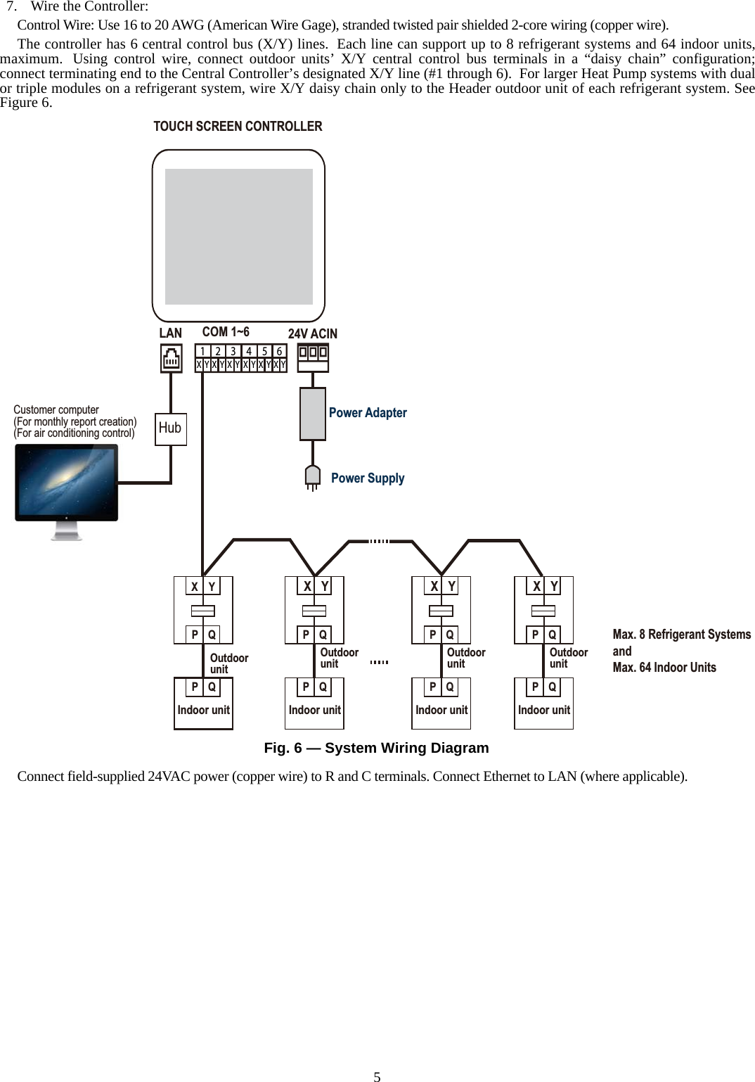
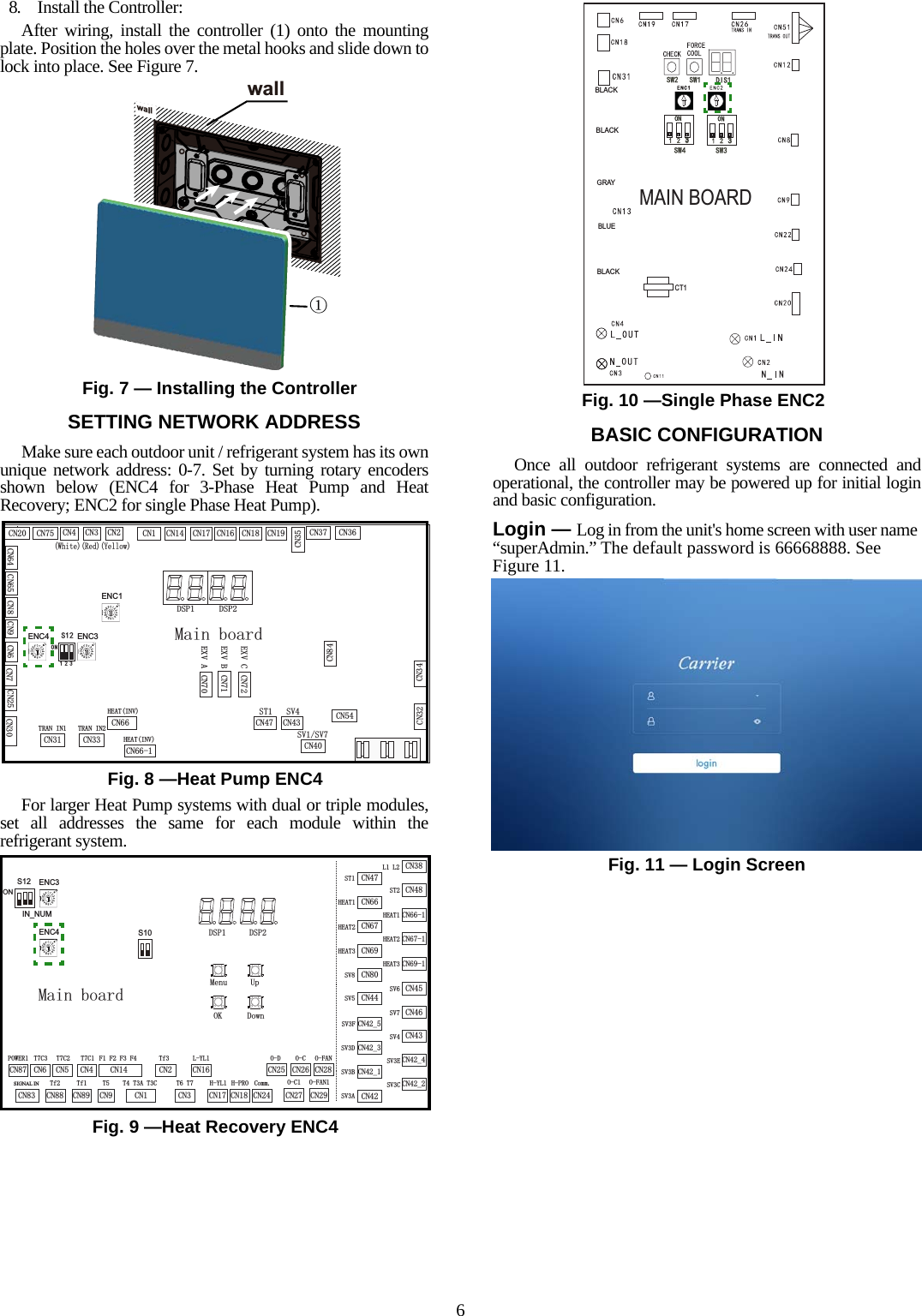
Carrier 40VM900006 Touch screen central controller User Manual 2AMPX 40VM900006 Users Manual rev1

Carrier Corporation Touch screen central controller 2AMPX 40VM900006 Users Manual rev1

2AMPX-40VM900006_Users Manual_rev1

harmful interference to radio communications. Operationaccordance with the instruction manual, may causeManufacturer reserves the right to discontinue, or change at any time, specifications or designs without notice and without incurring obligations.Catalog No. 17-40VM9006-01 Printed in China Form 40VM-5SIR1 Pg 1  09-17 Replaces: 40VM-5SIInstallation InstructionsPart Number 40VM900006For Commercial Use OnlyCONTENTSPageSAFETY CONSIDERATIONS.......................................1GENERAL..................................................................1DIMENSIONAL DRAWINGS.......................................... 2INSTALLATION CONSIDERATIONS.............................4INSTALLATION..........................................................4SETTING NETWORK ADDRESS.......................................6BASIC CONFIGURATION....................................................6•   LOGIN........................................................................6•   BRAND CHOICE.......................................................7•   AUTO SEARCH.........................................................7SAFETY CONSIDERATIONSRead and follow manufacturer instructions carefully. Follow all local electrical codes during installation. All wiring must conform to local and national electrical codes. Improper wiring or installation may damage thermostat.Understand the signal words — DANGER, WARNING, and CAUTION. DANGER identifies the most serious hazards which will result in severe personal injury or death. WARNING signifies hazards that could result in personal injury or death. CAUTION is used to identify unsafe practices, which would result in minor personal injury or product and property damage.Recognize safety information. Thissymbol ( ). When this symbol is displayed on the unit and in instructions or manuals, be alert to the potential for personal injury. Installing, starting up, and servicing equipment can be hazardous due to system pressure, electrical components, and equipment location.GENERALThe VRF (variable refrigerant flow) touch screen central controller is a wall-mounted, low-voltage controller that provides site-level control of multiple VRF systems. The controller allows central management of mode, setpoint, and scheduling of indoor units (IDUs). The touch screen central controller is available for usewith the VRF (variable refrigerant flow) outdoor units /systems listed in Table 1.NOTES:1. Changes or modifications of this product not expresslyapproved by the party responsible for compliance couldvoid the user's authority to operate the equipment.2. This equipment has been tested and found to comply withthe limits for a Class A digital device, pursuant to Part 15of the FCC Rules. These limits are designed to providereasonable protection against harmful interference whenthe equipment is operated in a commercial environment.This equipment generates, uses, and can radiate radioTable 1:  Touch Screen Central Controller Accessory Usage Table 2: Components shipped with UnitTable 3: SpecificationsUNIT SIZES38VMAR Heat Recovery System 072,096,120,144, 168, 192, 216, 240, 264, 288, 312, 33638VMAH Heat Pump System036, 048, 060, 072, 096, 120, 144, 168, 192, 216, 240, 264, 288, 312, 336, 360, 384, 408, 432NAME IMAGE QTY FUNCTIONMounting Box 1 Plastic mounting enclosureMounting Plate 1Steel plate connecting controller to front of Mounting BoxScrews (Short) 6Used to Install Mounting Box to WallScrews 4 Used to install Mounting Plate on Mounting BoxWashers 8Used to install Mounting Plate on Mounting Box(2 extra washers for fine adjustment if wall is uneven)Power Supply (field provided) Rated Voltage 24VAC, 60 HzCurrent Requirement 1ADimensions (inches)H7-3/8W 10-7/8D1-1/4Total Weight Touch Screen Controller, Mounting Box, Mounting Plate, & Screws: 2 lbs 12 ozNumber of X/Y Bus Lines 6Max. Refrigerant Systems/IDUs per Line 8/6438VM/40VM SeriesVRF (Variable Refrigerant Flow) SystemTouch Screen Central Controller Accessoryof this equipment in a residential area is likely to causeharmful interference-in which case the user will berequired to correct the interference at their own expense.This equipment should be installed and operated with a minimum distance of 20 centimeters between the radiatorand your body.
2DIMENSIONAL DRAWING10-7/8 7-3/8 1-1/4 3/8 Fig. 1 — Dimensions
3NAME FUNCTIONR 24VAC powerC 24VAC commonX X conductor, X/Y bus (no 1-6)Y Y conductor, X/Y bus (no 1-6)E Shield conductor, X/Y bus (no 1-6)DI1 Emergency Shutdown dry contact input*DI2 (reserved)DO1 (reserved)DO2 (reserved)AI1 (reserved)AI2 (reserved)LAN Local Area Network connection, EthernetUSB Universal Serial Bus connection for service*Emergency Shutdown input is not suitable for life-safety applications, such as fire or smoke sequences.Table 4 — Connection Description'2Ɣ'2$,Ɣ$,LANUSB9$&,1 ',Ɣ',&20aX1 E Y1 · X2 E Y2 · X3 E Y3R          C X4 E Y4 · X5 E Y5 · X6 E Y6 DI1 · DI2 DO1 · DO2 AI1 · AI2 LAN USB123456Fig. 2 — Connection Description
4INSTALLATION CONSIDERATIONSThe controller should be mounted:• at a location that allows easy access• on a section of wall without water or drainage pipesThe controller should NOT be mounted:• near heat sources such as direct sunlight, heaters, dimmer switches, and other electrical devices.INSTALLATIONTo install the controller, perform the following procedure:1. Turn off all power to the outdoor units, indoor units, andMDCs.2. Control Wire: Use 16 to 20 AWG (American Wire Gage), stranded twisted pair shielded 2-core wiring (copper wire). Be sure the distance between the controller and the furthest outdoor units is not more than 3937 ft. Field-Provided 24VAC Power Wire: Use copper wire rated for the current requirement shown in Table 3; follow all applicable electrical codes.3. For flush-mount installation, provide a 10-1/4" by 6-5/8" opening in drywall or mounting surface to accommodate the mounting box.4. Pull all wires through drywall or surface opening, and then through knockout(s) in Mounting Box.5. Install the Mounting Box (3) into the 10-1/4” by 6-5/8” opening in dry wall or mounting surface making sure the box is flush with the wall surface. See Figure 3. Use the 6 short screws to fasten the plastic mounting box. Use plastic washers as needed for alignment and to prevent damage to components.6. Install Mounting Plate:Make sure the metal hooks are facing upward. Attach themounting plate (2) onto the mounting box (3) using the fourlong screws (4) and four plastic washers. Do not overtighen thescrews. See Figures 4 and 5.WARNINGElectrical shock can cause personal injury and death. Before installing thermostat, shut off all power to this equipment during installation. There may be more than one power disconnect. Tag all disconnect locations to alert others not to restore power until work is completed.CAUTIONFailure to follow this caution may result in equipment damage or improper operation.Improper wiring or installation may damage the thermostat. Check to make sure wiring is correct before proceeding with installation or turning on unit.CAUTIONOver-tightening the screw will cause deformation tothe rear cover and LCD damage.Fig. 3 — Installing the Mounting BoxwallwallĸĺwallFig. 5 — Installing the Back Plate to BoxFig. 4 — Installing the Back Plate Washers
57. Wire the Controller:Control Wire: Use 16 to 20 AWG (American Wire Gage), stranded twisted pair shielded 2-core wiring (copper wire). The controller has 6 central control bus (X/Y) lines.  Each line can support up to 8 refrigerant systems and 64 indoor units,maximum.  Using control wire, connect outdoor units’ X/Y central control bus terminals in a “daisy chain” configuration;connect terminating end to the Central Controller’s designated X/Y line (#1 through 6).  For larger Heat Pump systems with dualor triple modules on a refrigerant system, wire X/Y daisy chain only to the Header outdoor unit of each refrigerant system. SeeFigure 6. Connect field-supplied 24VAC power (copper wire) to R and C terminals. Connect Ethernet to LAN (where applicable).Fig. 6 — System Wiring DiagramXY P   QOutdoorunitIndoor unitXYLANTOUCH SCREEN CONTROLLERPower AdapterPower Supply P Q P   Q  P  QOutdoorunitIndoor unitXY P Q P QOutdoorunitIndoor unitXY P Q P QOutdoorunitIndoor unitX Y123456X Y X Y X Y X Y X Y24V ACINCOM 1~6HubCustomer computer(For monthly report creation)(For air conditioning control)Max. 8 Refrigerant SystemsandMax. 64 Indoor Units
68. Install the Controller:After wiring, install the controller (1) onto the mountingplate. Position the holes over the metal hooks and slide down tolock into place. See Figure 7.SETTING NETWORK ADDRESSMake sure each outdoor unit / refrigerant system has its ownunique network address: 0-7. Set by turning rotary encodersshown below (ENC4 for 3-Phase Heat Pump and HeatRecovery; ENC2 for single Phase Heat Pump). For larger Heat Pump systems with dual or triple modules,set all addresses the same for each module within therefrigerant system.BASIC CONFIGURATIONOnce all outdoor refrigerant systems are connected andoperational, the controller may be powered up for initial loginand basic configuration.Login — Log in from the unit's home screen with user name “superAdmin.” The default password is 66668888. See Figure 11.Fig. 7 — Installing the ControllerķwallwallFig. 11 — Login Screen&167&169&16969&1&1+($7,19&1+($7,19&175$1,1&175$1,1&1(;9$&1(;9%&1&1&1&1&1&1&1&1&1&1&1 &1&1 &1 &1&1 &1 &1 &10DLQERDUG&1&1ENC1ENC3&1&1(;9&'63 '63216&1 &1 &1 &1:KLWH5HG<HOORZ&1ENC40DLQERDUG'63 '63&1+352&1+</&177&177$7&&1&1&1/</&17I&1))))&17&&17&&1SIGNAL IN7I7I2.8S0HQX'RZQ&1//&167&1+($7&1+($7&1+($7&169&169&169&1B69(&1B69&&167&1+($7&1+($7&1+($7&16969&169)&1B69'&1B69%&169$&1BENC3S12ONIN_NUM&132:(5&12)$1&12)$1&12&&12&&1&RPP&12'S10&17&17&ENC4CT133MAIN BOARDBLACKBLUEGRAYBLACKBLACKFig. 8 —Heat Pump ENC4Fig. 9 —Heat Recovery ENC4Fig. 10 —Single Phase ENC2
7Brand Choice — 1. Start up the Touch Screen Central Controller. Thefollowing splash screen will briefly be displayed:The following screen will be displayed:2. Select “Carrier” or “Bryant.” 3. Select “Always” or “Just Once.”One of the following screens will be displayed dependingon the user selection:4. Login to TSCC using the default user name andpassword. User Name: superAdminPassword: 66668888One of the following Home Screens will display dependingon whether the user chose Bryant or Carrier:5. Select “Setting” > “Hardware Testing.” The followingscreen will display:6. Select “Carrier” or “Bryant” and select “Test.”Auto Search — The Touch Screen Central Controller canautomatically search and connect to the system's connectedunits. Devices connected to the controller are automaticallysearched for and registered. You can register a deviceautomatically as follows. See Figures 14 and 15.1. In the main menu, click the [Install] menu icon.2. Click the [Auto Search] button. See Figure 15.Fig. 15 — Auto Search
Manufacturer reserves the right to discontinue, or change at any time, specifications or designs without notice and without incurring obligations.Catalog No. 17-40VM9006-01 Printed in China Form 40VM-5SIR1 Pg 8  09-17 Replaces: 40VM-5SIRefer to the User Manual for additional details on operation.

Navigation menu