Carrier 40VM900006 Touch screen central controller User Manual 2AMPX 40VM900006 Users Manual rev1
Carrier Corporation Touch screen central controller 2AMPX 40VM900006 Users Manual rev1
Carrier >
2AMPX-40VM900006_Users Manual_rev1
harmful interference to radio communications. Operation
accordance with the instruction manual, may cause
Manufacturer reserves the right to discontinue, or change at any time, specifications or designs without notice and without incurring obligations.
Catalog No. 17-40VM9006-01 Printed in China Form 40VM-5SIR1 Pg 1 09-17 Replaces: 40VM-5SI
Installation Instructions
Part Number 40VM900006
For Commercial Use Only
CONTENTS
Page
SAFETY CONSIDERATIONS.......................................1
GENERAL..................................................................1
DIMENSIONAL DRAWINGS.......................................... 2
INSTALLATION CONSIDERATIONS.............................4
INSTALLATION..........................................................4
SETTING NETWORK ADDRESS.......................................6
BASIC CONFIGURATION....................................................6
• LOGIN........................................................................6
• BRAND CHOICE.......................................................7
• AUTO SEARCH.........................................................7
SAFETY CONSIDERATIONS
Read and follow manufacturer instructions carefully.
Follow all local electrical codes during installation. All wiring
must conform to local and national electrical codes. Improper
wiring or installation may damage thermostat.
Understand the signal words — DANGER, WARNING,
and CAUTION. DANGER identifies the most serious hazards
which will result in severe personal injury or death.
WARNING signifies hazards that could result in personal
injury or death. CAUTION is used to identify unsafe practices,
which would result in minor personal injury or product and
property damage.
Recognize safety information. This
symbol ( ). When this symbol is displayed on the unit and in
instructions or manuals, be alert to the potential for personal
injury. Installing, starting up, and servicing equipment can be
hazardous due to system pressure, electrical components, and
equipment location.
GENERAL
The VRF (variable refrigerant flow) touch screen central
controller is a wall-mounted, low-voltage controller that
provides site-level control of multiple VRF systems. The
controller allows central management of mode, setpoint,
and scheduling of indoor units (IDUs).
The touch screen central controller is available for use
with the VRF (variable refrigerant flow) outdoor units /
systems listed in Table 1.
NOTES:
1. Changes or modifications of this product not expressly
approved by the party responsible for compliance could
void the user's authority to operate the equipment.
2. This equipment has been tested and found to comply with
the limits for a Class A digital device, pursuant to Part 15
of the FCC Rules. These limits are designed to provide
reasonable protection against harmful interference when
the equipment is operated in a commercial environment.
This equipment generates, uses, and can radiate radio
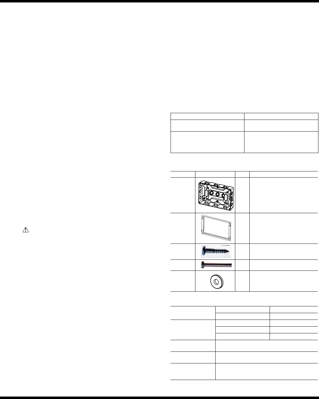
Table 1: Touch Screen Central Controller
Accessory Usage
Table 2: Components shipped with Unit
Table 3: Specifications
UNIT SIZES
38VMAR Heat Recovery System 072,096,120,144, 168, 192, 216,
240, 264, 288, 312, 336
38VMAH Heat Pump System
036, 048, 060, 072, 096, 120,
144, 168, 192, 216, 240, 264,
288, 312, 336, 360, 384, 408,
432
NAME IMAGE QTY FUNCTION
Mounting
Box 1 Plastic mounting enclosure
Mounting
Plate 1Steel plate connecting
controller to front of Mounting
Box
Screws
(Short) 6Used to Install Mounting Box
to Wall
Screws 4 Used to install Mounting Plate
on Mounting Box
Washers 8
Used to install Mounting Plate
on Mounting Box
(2 extra washers for fine
adjustment if wall is uneven)
Power Supply
(field provided) Rated Voltage 24VAC, 60 Hz
Current Requirement 1A
Dimensions
(inches)
H7-3/8
W 10-7/8
D1-1/4
Total Weight Touch Screen Controller, Mounting Box,
Mounting Plate, & Screws: 2 lbs 12 oz
Number of X/Y
Bus Lines 6
Max. Refrigerant
Systems/IDUs
per Line 8/64
38VM/40VM Series
VRF (Variable Refrigerant Flow) System
Touch Screen Central Controller Accessory
of this equipment in a residential area is likely to cause
harmful interference-in which case the user will be
required to correct the interference at their own expense.
This equipment should be installed and operated with a
minimum distance of 20 centimeters between the radiator
and your body.
2
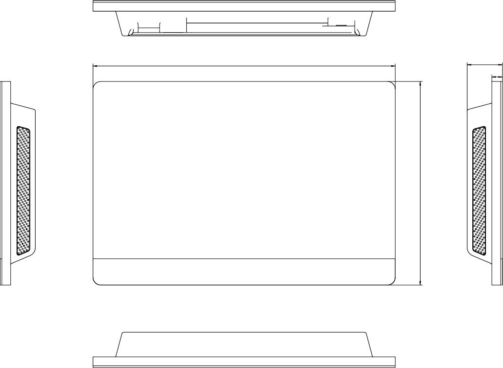
DIMENSIONAL DRAWING
10-7/8
7-3/8
1-1/4
3/8
Fig. 1 — Dimensions
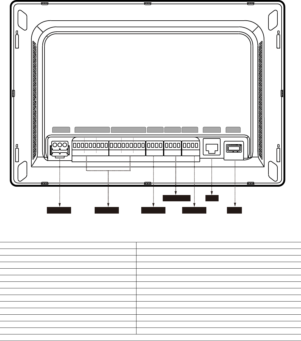
3
NAME FUNCTION
R 24VAC power
C 24VAC common
X X conductor, X/Y bus (no 1-6)
Y Y conductor, X/Y bus (no 1-6)
E Shield conductor, X/Y bus (no 1-6)
DI1 Emergency Shutdown dry contact input*
DI2 (reserved)
DO1 (reserved)
DO2 (reserved)
AI1 (reserved)
AI2 (reserved)
LAN Local Area Network connection, Ethernet
USB Universal Serial Bus connection for service
*Emergency Shutdown input is not suitable for life-safety applications, such as fire or smoke sequences.
Table 4 — Connection Description
'2Ɣ'2
$,Ɣ$,
LAN
USB9$&,1 ',Ɣ',&20a
X1 E Y1 · X2 E Y2 · X3 E Y3
R C X4 E Y4 · X5 E Y5 · X6 E Y6 DI1 · DI2 DO1 · DO2 AI1 · AI2 LAN USB
123456
Fig. 2 — Connection Description
4
INSTALLATION CONSIDERATIONS
The controller should be mounted:
• at a location that allows easy access
• on a section of wall without water or drainage pipes
The controller should NOT be mounted:
• near heat sources such as direct sunlight, heaters, dimmer
switches, and other electrical devices.
INSTALLATION
To install the controller, perform the following procedure:
1. Turn off all power to the outdoor units, indoor units, and
MDCs.
2. Control Wire: Use 16 to 20 AWG (American Wire Gage),
stranded twisted pair shielded 2-core wiring (copper
wire). Be sure the distance between the controller and the
furthest outdoor units is not more than 3937 ft. Field-
Provided 24VAC Power Wire: Use copper wire rated
for the current requirement shown in Table 3; follow
all applicable electrical codes.
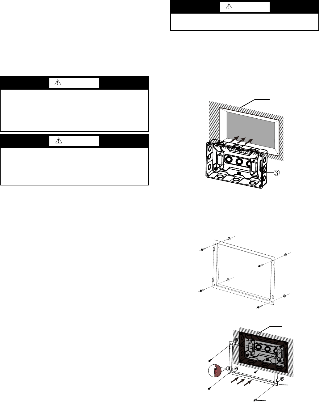
3. For flush-mount installation, provide a 10-1/4" by 6-5/8"
opening in drywall or mounting surface to accommodate
the mounting box.
4. Pull all wires through drywall or surface opening, and
then through knockout(s) in Mounting Box.
5. Install the Mounting Box (3) into the 10-1/4” by 6-5/
8” opening in dry wall or mounting surface making
sure the box is flush with the wall surface. See Figure
3. Use the 6 short screws to fasten the plastic mounting
box. Use plastic washers as needed for alignment and
to prevent damage to components.
6. Install Mounting Plate:
Make sure the metal hooks are facing upward. Attach the
mounting plate (2) onto the mounting box (3) using the four
long screws (4) and four plastic washers. Do not overtighen the
screws. See Figures 4 and 5.
WARNING
Electrical shock can cause personal injury and death.
Before installing thermostat, shut off all power to this
equipment during installation. There may be more
than one power disconnect. Tag all disconnect
locations to alert others not to restore power until
work is completed.
CAUTION
Failure to follow this caution may result in equipment
damage or improper operation.
Improper wiring or installation may damage the
thermostat. Check to make sure wiring is correct
before proceeding with installation or turning on unit.
CAUTION
Over-tightening the screw will cause deformation to
the rear cover and LCD damage.
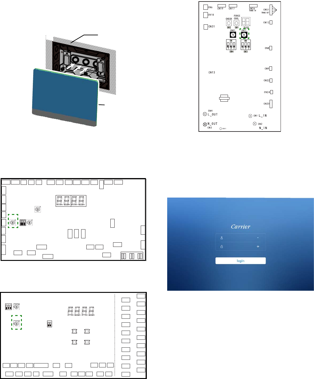
Fig. 3 — Installing the Mounting Box
wall
wall
ĸ
ĺ
wall
Fig. 5 — Installing the Back Plate to Box
Fig. 4 — Installing the Back Plate Washers
5
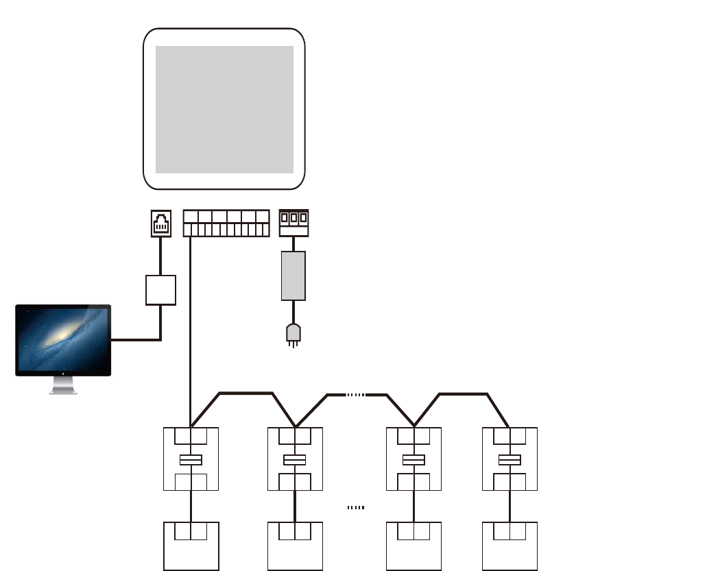
7. Wire the Controller:
Control Wire: Use 16 to 20 AWG (American Wire Gage), stranded twisted pair shielded 2-core wiring (copper wire).
The controller has 6 central control bus (X/Y) lines. Each line can support up to 8 refrigerant systems and 64 indoor units,
maximum. Using control wire, connect outdoor units’ X/Y central control bus terminals in a “daisy chain” configuration;
connect terminating end to the Central Controller’s designated X/Y line (#1 through 6). For larger Heat Pump systems with dual
or triple modules on a refrigerant system, wire X/Y daisy chain only to the Header outdoor unit of each refrigerant system. See
Figure 6.
Connect field-supplied 24VAC power (copper wire) to R and C terminals. Connect Ethernet to LAN (where applicable).
Fig. 6 — System Wiring Diagram
XY
P Q
Outdoor
unit
Indoor unit
XY
LAN
TOUCH SCREEN CONTROLLER
Power Adapter
Power Supply
P Q
P Q P Q
Outdoor
unit
Indoor unit
XY
P Q
P Q
Outdoor
unit
Indoor unit
XY
P Q
P Q
Outdoor
unit
Indoor unit
X Y
123456
X Y X Y X Y X Y X Y
24V ACIN
COM 1~6
Hub
Customer computer
(For monthly report creation)
(For air conditioning control)
Max. 8 Refrigerant Systems
and
Max. 64 Indoor Units
6
8. Install the Controller:
After wiring, install the controller (1) onto the mounting
plate. Position the holes over the metal hooks and slide down to
lock into place. See Figure 7.
SETTING NETWORK ADDRESS
Make sure each outdoor unit / refrigerant system has its own
unique network address: 0-7. Set by turning rotary encoders
shown below (ENC4 for 3-Phase Heat Pump and Heat
Recovery; ENC2 for single Phase Heat Pump).
For larger Heat Pump systems with dual or triple modules,
set all addresses the same for each module within the
refrigerant system.
BASIC CONFIGURATION
Once all outdoor refrigerant systems are connected and
operational, the controller may be powered up for initial login
and basic configuration.
Login — Log in from the unit's home screen with user name
“superAdmin.” The default password is 66668888. See
Figure 11.
Fig. 7 — Installing the Controller
ķ
wall
wall
Fig. 11 — Login Screen
&1
67
&1
69
&1
6969
&1
&1
+($7,19
&1
+($7,19
&1
75$1,1
&1
75$1,1
&1(;9$
&1
(;9%
&1
&1&1&1
&1
&1
&1&1&1&1
&1 &1
&1 &1 &1&1 &1 &1 &1
0DLQERDUG
&1
&1
ENC1
ENC3
&1
&1(;9&
'63 '63
21
6
&1 &1 &1 &1
:KLWH5HG<HOORZ
&1
ENC4
0DLQERDUG
'63 '63
&1
+352
&1
+</
&1
77
&1
77$7&
&1&1
&1
/</
&1
7I
&1
))))
&1
7&
&1
7&
&1
SIGNAL IN
7I7I
2.
8S0HQX
'RZQ
&1
//
&1
67
&1
+($7
&1
+($7
&1
+($7
&1
69
&1
69
&1
69
&1B
69(
&1B
69&
&1
67
&1
+($7
&1
+($7
&1
+($7
&1
69
69
&1
69)
&1B
69'
&1B
69%
&1
69$
&1B
ENC3
S12
ON
IN_NUM
&1
32:(5
&1
2)$1
&1
2)$1
&1
2&
&1
2&
&1
&RPP
&1
2'
S10
&1
7
&1
7&
ENC4
CT1
3
3
MAIN BOARD
BLACK
BLUE
GRAY
BLACK
BLACK
Fig. 8 —Heat Pump ENC4
Fig. 9 —Heat Recovery ENC4
Fig. 10 —Single Phase ENC2
7
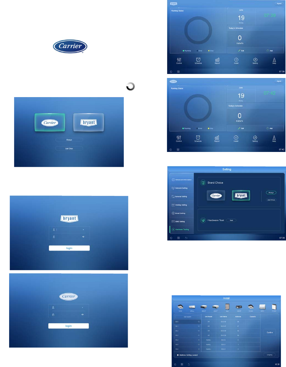
Brand Choice —
1. Start up the Touch Screen Central Controller. The
following splash screen will briefly be displayed:
The following screen will be displayed:
2. Select “Carrier” or “Bryant.”
3. Select “Always” or “Just Once.”
One of the following screens will be displayed depending
on the user selection:
4. Login to TSCC using the default user name and
password.
User Name: superAdmin
Password: 66668888
One of the following Home Screens will display depending
on whether the user chose Bryant or Carrier:
5. Select “Setting” > “Hardware Testing.” The following
screen will display:
6. Select “Carrier” or “Bryant” and select “Test.”
Auto Search — The Touch Screen Central Controller can
automatically search and connect to the system's connected
units. Devices connected to the controller are automatically
searched for and registered. You can register a device
automatically as follows. See Figures 14 and 15.
1. In the main menu, click the [Install] menu icon.
2. Click the [Auto Search] button. See Figure 15.
Fig. 15 — Auto Search

Manufacturer reserves the right to discontinue, or change at any time, specifications or designs without notice and without incurring obligations.
Catalog No. 17-40VM9006-01 Printed in China Form 40VM-5SIR1 Pg 8 09-17 Replaces: 40VM-5SI
Refer to the User Manual for additional details on operation.