Caterpillar WCA1 Wireless Communication Adapter User Manual Nehs0926 01
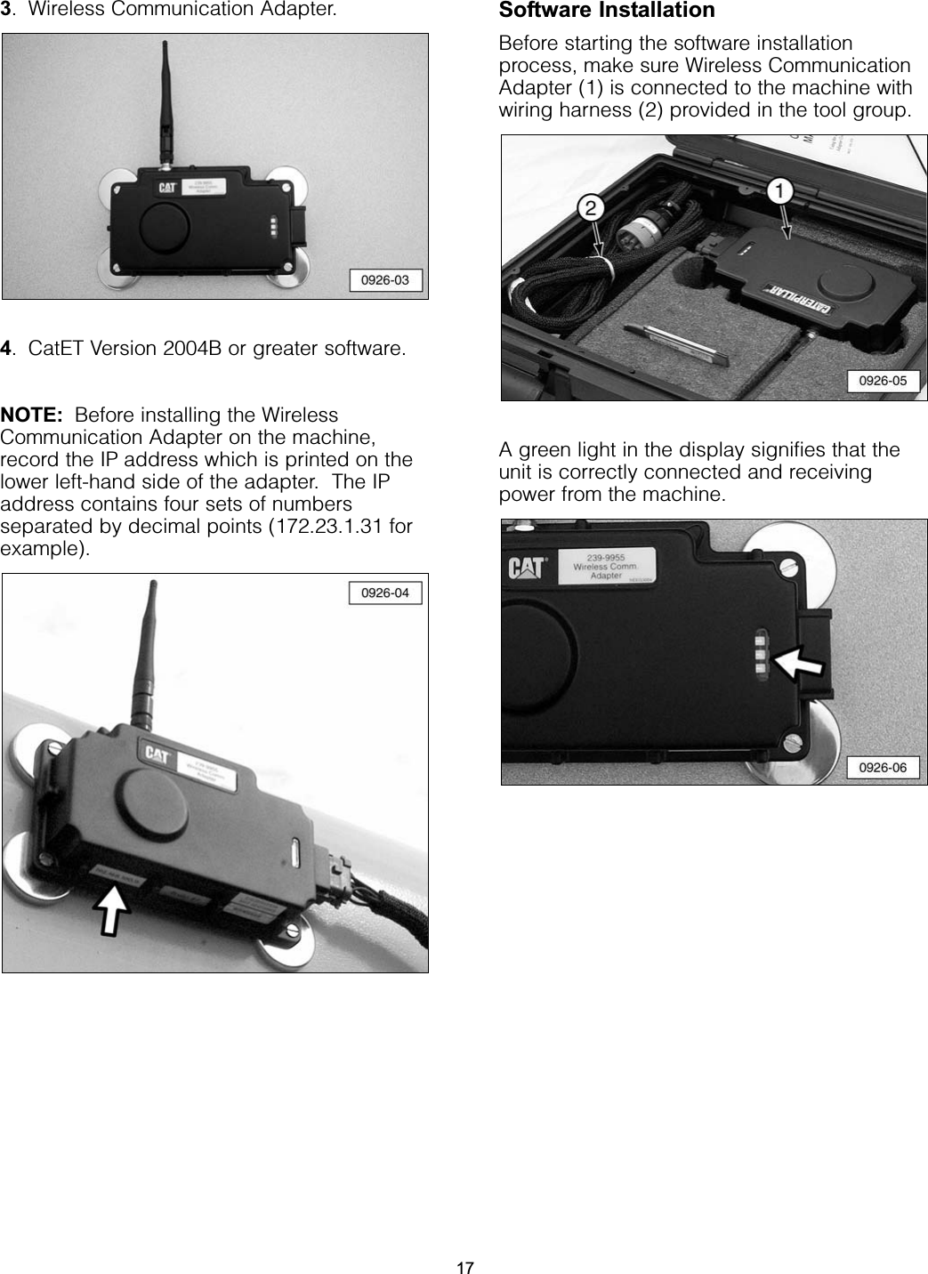
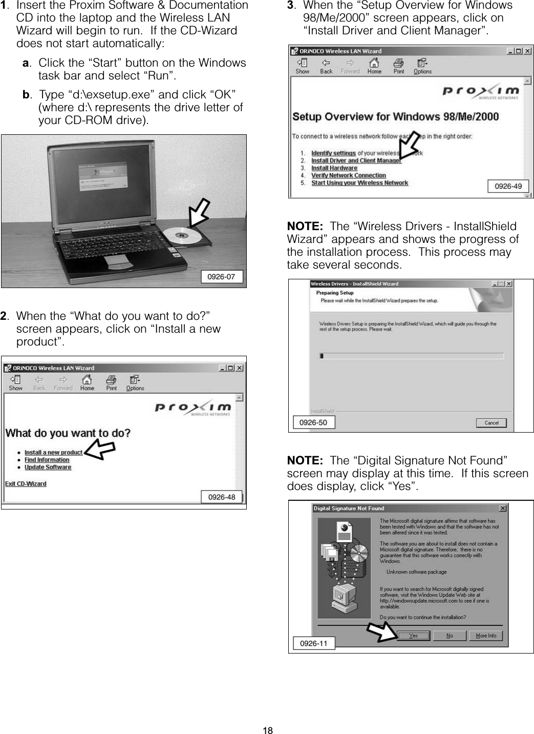
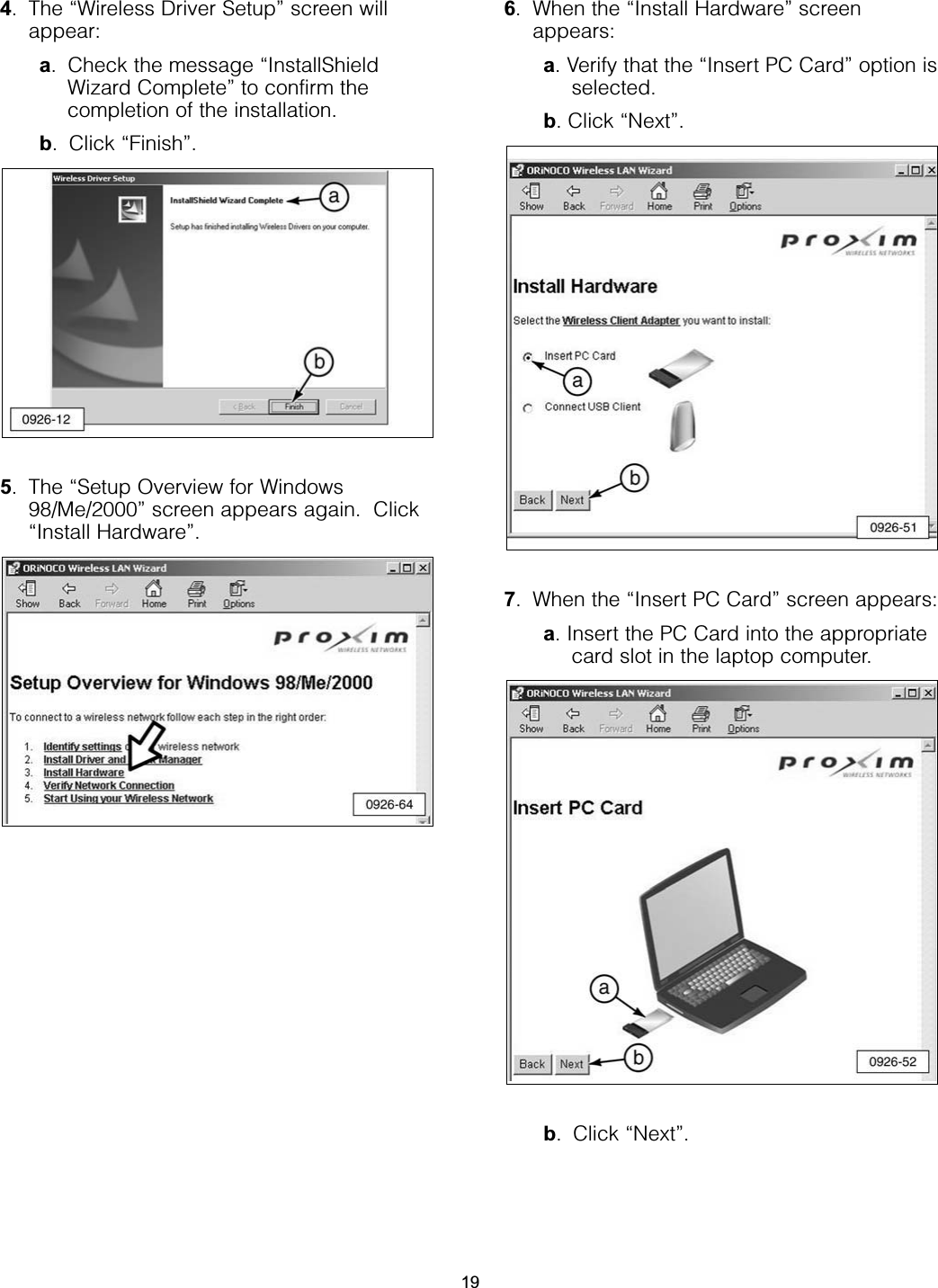
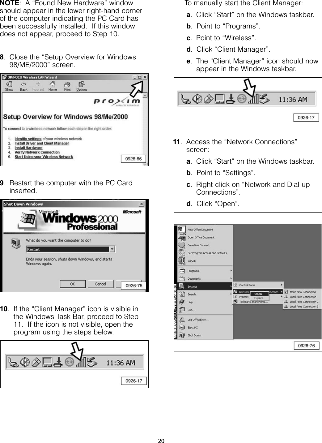
Caterpillar, Inc. Wireless Communication Adapter Nehs0926 01
UserManual.wiki
>
Caterpillar
>
WCA1 User Manual
Users Manual Revised
Navigation menu
Upload a User Manual
Namespaces
Wiki Guide
HTML
PDF
Info
Views
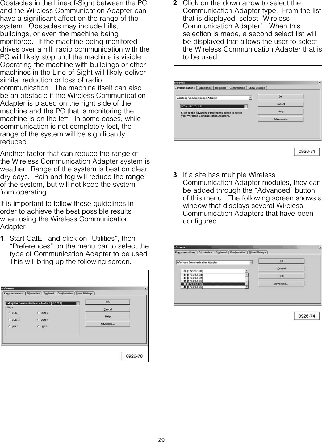
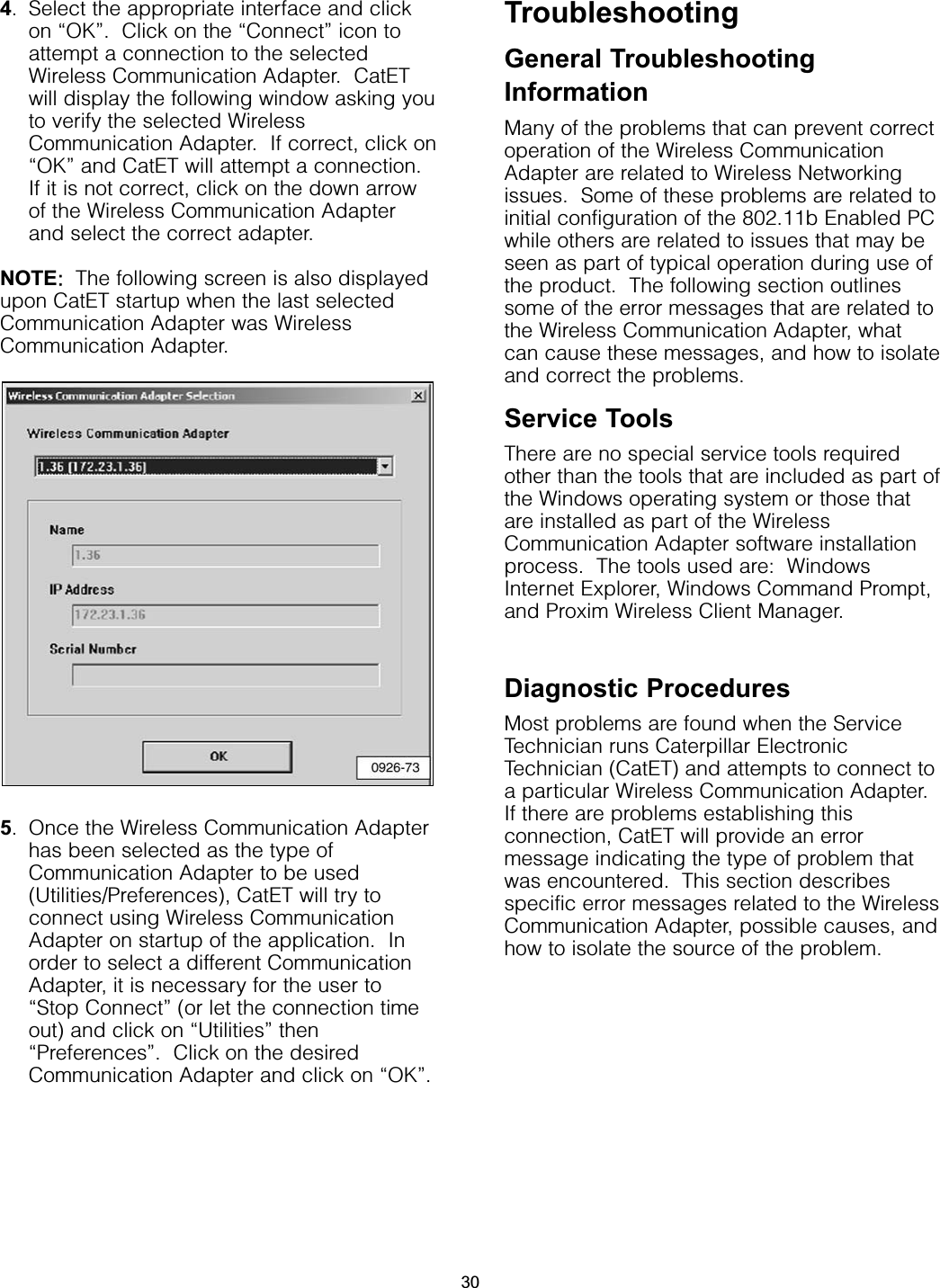
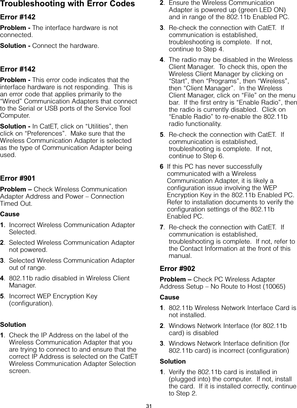
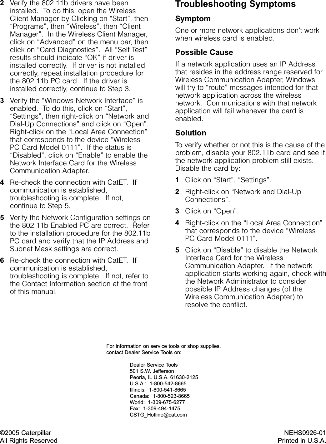
User Manual
Discussion / Help
Navigation