Caterpillar WCA1 Wireless Communication Adapter User Manual Nehs0926 01
Caterpillar, Inc. Wireless Communication Adapter Nehs0926 01
Users Manual Revised

Using the 261-3363 Wireless Communication
Adapter
SMCS: 1900
TOOL
OPERATING
MANUAL
R
TOOL
OPERATING
MANUAL
NEHS0926-01
January 2005

Important Safety Information
Think Safety
Most accidents that involve product operation,
maintenance, and repair are caused by failure
to observe basic safety rules or precautions.
An accident can often be avoided by
recognizing potentially hazardous situations
before an accident occurs. A person must be
alert to potential hazards. This person should
also have the necessary training, skills, and
tools to perform these functions properly.
Improper operation, lubrication,
maintenance, or repair of this product can
be dangerous and could result in injury or
death.
Do not operate or perform any lubrication,
maintenance, or repair on this product until
you have read and understood the
operation, lubrication, maintenance, and
repair information.
Safety precautions and warnings are provided
in this manual and on the product. If these
hazard warnings are not heeded, bodily injury
or death could occur to you or to other
persons.
The hazards are identified by the “Safety Alert
Symbol” and followed by a “Signal Word” such
as “DANGER”, “WARNING”, or “CAUTION”.
The Safety Alert “WARNING” label is shown
below.
The meaning of this safety alert symbol is as
follows:
Attention! Become Alert! Your Safety is
Involved.
The message that appears under the warning
explains the hazard and can be either written
or pictorially presented.
Operations that may cause product damage
are identified by “NOTICE” labels on the
product and in this publication.
Caterpillar cannot anticipate every possible
circumstance that might involve a potential
hazard. The warnings in this publication
and on the product are, therefore, not all
inclusive. If a tool, procedure, work
method, or operating technique that is not
specifically recommended by Caterpillar is
not used, you must satisfy yourself that it is
safe for you and for others. You should
also ensure that the product will not be
damaged or be made unsafe by the
operation, lubrication, maintenance or
repair procedures that you choose.
The information, specifications, and illustrations
in this publication are on the basis of
information that was available at the time that
the publication was written. The specifications,
torques, pressures, measurements,
adjustments, illustrations, and other items can
change at any time. These changes can affect
the service that is given to the product. Obtain
the complete and most current information
before you start any job.
When replacement parts are required for this
product, Caterpillar recommends using
Caterpillar replacement parts or parts with
equivalent specifications including, but not
limited to, physical dimensions, type,
strength, and material.
Failure to heed this warning can lead to
premature failures, product damage,
personal injury, or death.
WARNING
WARNING
2
Contents
System Overview . . . . . . . . . . . . . . . . . . . . . . 4
Product Description . . . . . . . . . . . . . . . . . . 4
Wireless Communication Adapter . . . . . . . 4
Data Link Harness . . . . . . . . . . . . . . . . . . . 4
802.11b Enabled PC . . . . . . . . . . . . . . . . . 4
Network Interface. . . . . . . . . . . . . . . . . . . . 5
Parts List . . . . . . . . . . . . . . . . . . . . . . . . . . . . 5
Optional Accessories. . . . . . . . . . . . . . . . . 5
System Requirements . . . . . . . . . . . . . . . . 5
Recommended PC Configuration . . . . . . . 5
Minimum Software Requirements . . . . . . . 5
Network Requirements . . . . . . . . . . . . . . . 5
Specifications. . . . . . . . . . . . . . . . . . . . . . . 5
Operating Instructions . . . . . . . . . . . . . . . . . . 6
Software Installation. . . . . . . . . . . . . . . . . . . . 6
Windows XP Operating System. . . . . . . . . 7
Required Hardware and Software . . . . . 7
Software Installation. . . . . . . . . . . . . . . . 8
Windows 2000 Operating System . . . . . . 16
Required Hardware and Software . . . . 16
Software Installation. . . . . . . . . . . . . . . 17
Configure Cat Electronic Technician for the
Wireless Communication Adapter . . . . . . . . 25
Using the Wireless Communication . . . . . . 28
Adapter
Troubleshooting . . . . . . . . . . . . . . . . . . . . . . 30
General Troubleshooting Information . . . 30
Service Tools . . . . . . . . . . . . . . . . . . . . . . 30
Diagnostic Procedures . . . . . . . . . . . . . . 30
Troubleshooting with Error Codes . . . . . . 31
Troubleshooting Symptoms . . . . . . . . . . . 32
Contact Information
The IP address is printed on each Wireless
Communication Adapter. If the factory default
IP Address on the Wireless Communication
Adapter has been changed, or for any other
software issues, contact Product Support:
Illinois - (800) 541-8665
Outside Illinois - (800) 542-8665
Canada - (800) 523-8665
Fax: 1-309-494-1475
CSTG_Hotline@cat.com
3
System Overview
Product Description
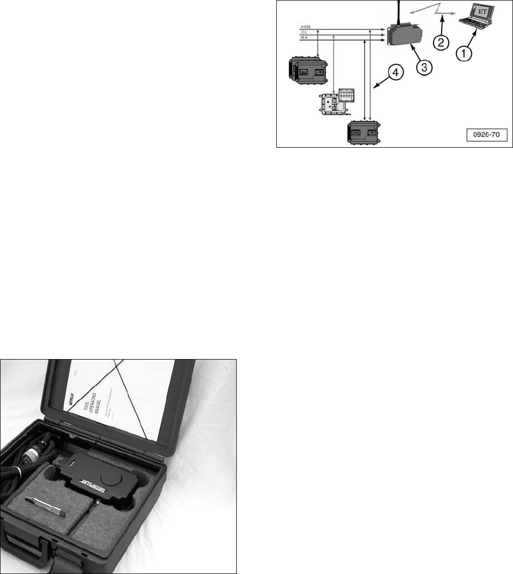
The 261-3363 Wireless Communication
Adapter (WCA) is a service tool for remotely
monitoring machine or engine operation using
CatET and an 802.11 enabled PC. The group
consists of a portable hardware adapter and a
software program designed to run under
Microsoft Windows (XP, 2000, ME, or 98). It
will allow a laptop computer (PC) to aid in the
monitoring of ECM communication (3) on
J1939/11 high speed data link, CAT DataLink,
and J1708 (ATA) vehicle networks.
Communication between the Wireless
Communication Adapter (2) and the PC with
CatET (1) is transmitted through an 802.11b
wireless network.
The 261-3363 Wireless Communication
Adapter is available as a group that contains
all the necessary cables and software required
for using the Wireless Communication Adapter
on Caterpillar products. Replacement parts
can also be purchased separately. For a list of
the parts contained in the group, refer to the
Parts List section.
1. Laptop computer with Cat Electronic Technician
(CatET). 2. 802.11b wireless network. 3. Wireless
Communication Adapter. 4. ECM.
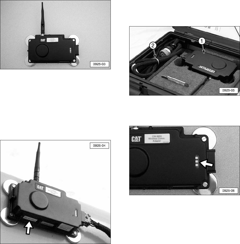
Wireless Communication Adapter
The Wireless Communication Adapter module
combines the functionality of a Communication
Adapter with an 802.11b radio. The module is
mounted to the machine with magnetic mounts
and connects to the on-board data links (CAT
Data Link, J1939 and ATA) through a Data Link
Harness. The module translates the data link
traffic into messages that are communicated
via the 802.11b Wireless Network to the
802.11b Enabled PC running Caterpillar ET.
Data Link Harness
The Data Link Harness connects the Wireless
Communication Adapter to the diagnostic port
on the radio. Note that the harness length
must not be extended, as functionality will be
lost.
802.11b Enabled PC
Caterpillar Electronic Technician is used on a
PC to display information about the machine.
An 802.11 network card is required for the PC
to communicate with the Wireless
Communication Adapter.
4

Network Interface
The Wireless Communication Adapter system
relies on an 802.11b radio network. The radio
network is configured to operate in Ad Hoc
mode (Channel 11) and utilizes an IP Address
Range in Private Address space (172.23.x.x)
by default but can be changed as needed
based on the site-specific network
requirements. WEP (Wired Equivalent Privacy)
is enabled with a default static WEP key. This
too can be configured based on local
requirements. For information regarding the
modification of settings for the Wireless
Communication Adapter, refer to the Contact
Information section at the front of this manual.
Contact your local Network Administrator for
more information and assistance in changing
and documenting these settings.
Parts List
The 261-3363 Wireless Communication
Adapter Group consists of:
Part Number Description
239-9955 Wireless Communication Adapter
259-3183 Data Link Cable
261-4867 802.11b PC Card and Software CD
262-7732 Magnetic Feet (4 required)
261-3381 Foam Insert (for carrying case)
6V-3072 Carrying Case
154-6315 Machine Screw (4 required)
8T-0328 Washer (4 required)
6D-5801 Locknut (4 required)
NEHS0926 Tool Operating Manual
Optional Accessories
Part Number Description
250-2349 Wireless Communication Adapter Antenna
(Service Replacement)
261-4871 PCMCIA Card Range Extender Antenna
(Optional Accessory)
System Requirements
To successfully operate the Wireless
Communication Adapter, the following PC
hardware and software is required:
Recommended PC Configuration
• 128 MB of RAM
• CD-ROM drive
• IBM® PC compatible with Pentium III 450
MHz processor or greater
Minimum Software Requirements
• Microsoft® Windows™ XP, 2000, ME, or
98
Network Requirements
• 802.11b Wireless Network
• Ad Hoc Mode / Channel 11
• WEP Encryption – 128-Bit Static Key
• 172.23.x.x Private Addressing Range
• IP Address / Subnet and WEP key
configurable
Specifications
Description Specification
Operating Voltage 9V DC – 32V DC, 3.6 watts typical,
4 watts maximum
Operating Temperature -40°C to +70°C
(-40°F to +158°F)
Overall Size (without magnets) 213.9 x 119.9 x 45.2 mm
(8.42 x 4.72 x 1.78 in)
Weight (without magnets) 472 g (1.04 lb)
Vehicle Protocols Supported:
Cat Data Link (CDL)
ATA (SAE J1708)
SAE J1939
Wireless Communication TCP/IP over 802.11b (11 Mb)
Wireless Communication Range (line of site)
Standard Configuration 152 M (500 ft.)
With PCMCIA Card Range Extender
Antenna (optional) 244 M (800 ft.)
NOTE: All specifications are subject to change without notice.
5
Operating Instructions
The Wireless Communication Adapter
connects between the service connector on
the Caterpillar product being tested and a
laptop computer (PC) through an 802.11b
Wireless Network.
If the service connector is powered when the
Wireless Communication Adapter is connected
to the data link, the green POWER light on the
Wireless Communication Adapter will glow.
When power is first applied, the Wireless
Communication Adapter performs a diagnostic
test by turning on all three of the lights at the
same time.
Before using the Wireless Communication
Adapter hardware and software, complete the
steps below to ensure that the system will
operate properly, effectively, and without error.
To operate the Wireless Communication
Adapter, complete the steps listed below:
1. Review the “System Requirements” section
(especially Network requirements) with the
Network Administrator to ensure that the
Wireless Communication Adapter does not
interfere with any other software or
hardware applications.
2. Install the communication software using
the correct installation procedure contained
in this manual for the operating software
being used on the PC.
3. Configure the Caterpillar Electronic
Technician (CatET) for the Wireless
Communication Adapter.
4. Read the “Using the Wireless
Communication Adapter” section in this
manual.
Software Installation
The installation of the software to operate the
Wireless Communication Adapter depends on
the operating system of the computer. This
section of the manual contains two separate
software installation procedures, depending on
the operating system. The first procedure
covers the software installation onto computers
operating under the Windows XP operating
software. The second section covers the
Windows 2000 operating system. The
installation procedures for Windows ME and
98 can be found on the Caterpillar Dealer web
site.
NOTE: Please review documentation that is
provided by the supplier of the Wireless LAN
PC Card (ORiNOCO / Proxim) regarding
Software License Agreement and Regulatory
Information. This can be found on the
Software Installation CD by selecting “Find
Information” at the “What do you want to do?”
screen.
6
Windows XP Operating System
In order for Cat Electronic Technician (CatET)
to operate in a wireless mode, the laptop and
CatET must both be configured. This section
provides step-by-step instructions for installing
and configuring the wireless PC Card installed
in the laptop computer. Refer to the section
“Configure Cat Electronic Technician for the
Wireless Communication Adapter” for step-by-
step instructions for configuring the CatET to
communicate through the Wireless
Communication Adapter (WCA).
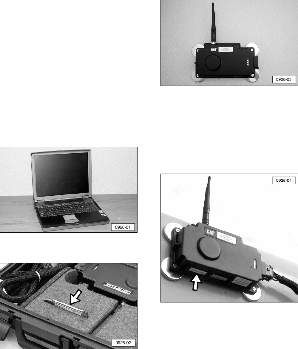
Required Hardware and Software
In addition to these instructions, you will need
four items in order to successfully complete
the installation and configuration:
1. A laptop with a CD drive (refer to the
“System Requirements” section in this
manual for additional information).
2. A “Proxim PC Card” and software CD (part
of the tool group).
3. Wireless Communication Adapter.
4. CatET Version 2004B or greater software.
NOTE: Before installing the Wireless
Communication Adapter on the machine,
record the IP address which is printed on the
lower left-hand side of the adapter. The IP
address contains four sets of numbers
separated by decimal points (172.23.1.31 for
example).
7
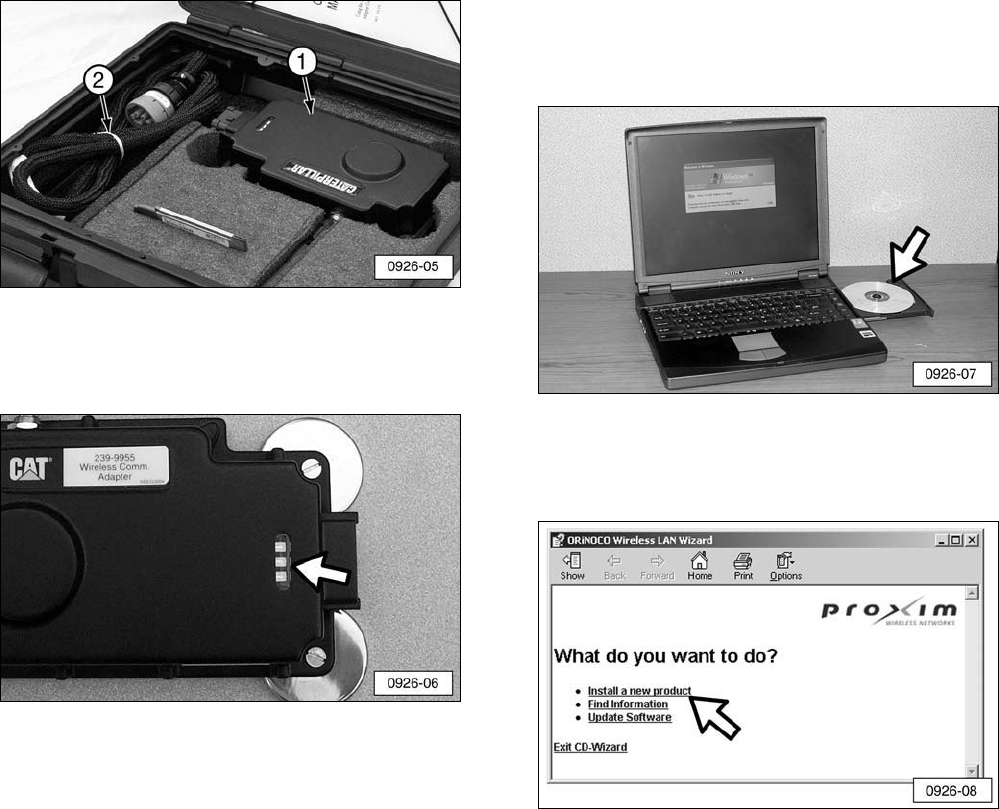
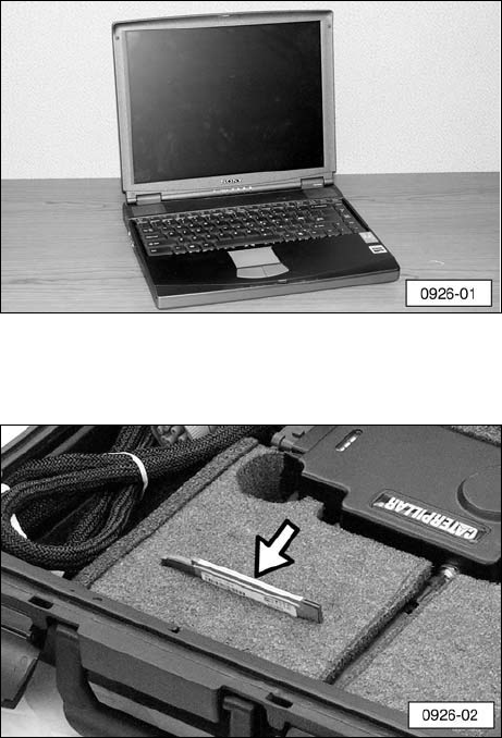
Software Installation
Before starting the software installation
process, make sure Wireless Communication
Adapter (1) is connected to the machine with
wiring harness (2) provided in the tool group.
A green light in the display signifies that the
unit is correctly connected and receiving
power from the machine.
1. Insert the Proxim Software & Documentation
CD into the laptop and the Wireless LAN
Wizard will begin to run. If the CD-Wizard
does not start automatically:
a. Click the “Start” button on the Windows
task bar and select “Run”.
b. Type “d:\exsetup.exe” and click “OK”
(where d:\ represents the drive letter of
your CD-ROM drive).
2. When the “What do you want to do?”
screen appears, click on “Install a new
product”.
8
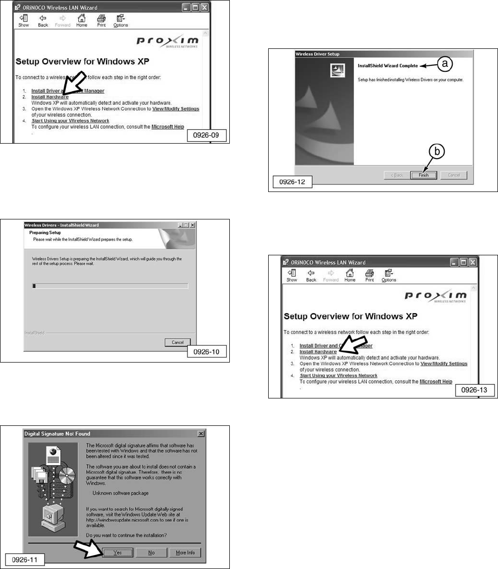
3. When the “Setup Overview for Windows XP”
screen appears, click on “Install Driver and
Client Manager”.
NOTE: The “Wireless Drivers - InstallShield
Wizard” appears and shows the progress of
the installation process. This process may
take several seconds.
NOTE: The “Digital Signature Not Found”
screen may display at this time. If this screen
does display, click “Yes”.
4. The “Wireless Driver Setup” screen will
appear:
a. Check the message “InstallShield
Wizard Complete” to confirm the
completion of the installation.
b. Click “Finish”.
5. The “Setup Overview for Windows XP”
screen appears again. Click “Install
Hardware”.
9
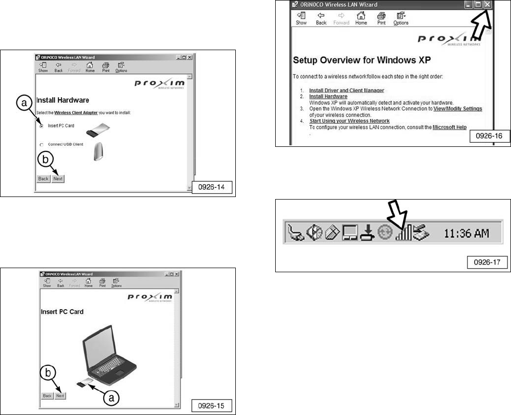
6. When the “Install Hardware” screen
appears:
a. Verify that the “Insert PC Card” option is
selected.
b. Click “Next”.
7. When the “Insert PC Card” screen appears:
a. Insert the PC Card into the appropriate
card slot in the laptop.
b. Click “Next”.
NOTE: A “Found New Hardware” window
should appear in the lower right-hand corner
of the computer indicating the PC Card has
been successfully installed. If this window
does not appear, proceed to Step 10.
8. Close the “Setup Overview for Windows XP”
screen.
9. If the “Client Manager” icon is visible in the
Windows Task Bar, proceed to Step 11.
10
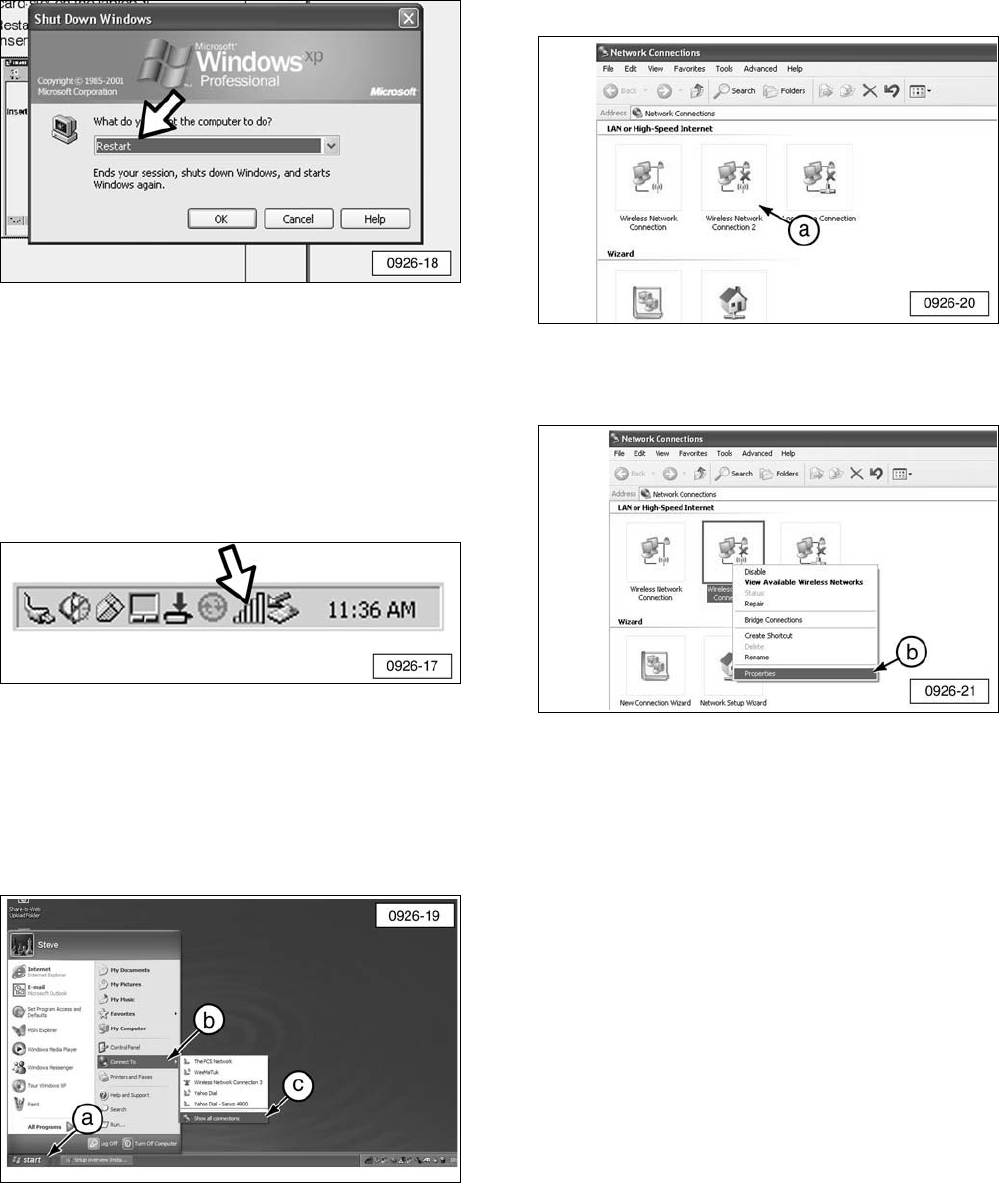
10. If the computer does not recognize the PC
Card or if the Client Manager icon is not
visible, restart the computer with the PC
Card inserted.
To manually start the Client Manager:
a. Click “Start” on the Windows taskbar.
b. Point to “Programs”.
c. Point to “Wireless”.
d. Click “Client Manager”.
d. The “Client Manager” icon should now
appear in the Windows taskbar.
11. Access the “Network Connections”
screen:
a. Click “Start” on the Windows taskbar.
b. Click “Connect To”.
c. Click “Show all connections”.
12. When the “Network Connections” screen
appears:
a. Right-click on the “Wireless Network
Connection” icon. This icon is for the
“Wireless PC Card Model 0111”.
b. Select “Properties”.
11
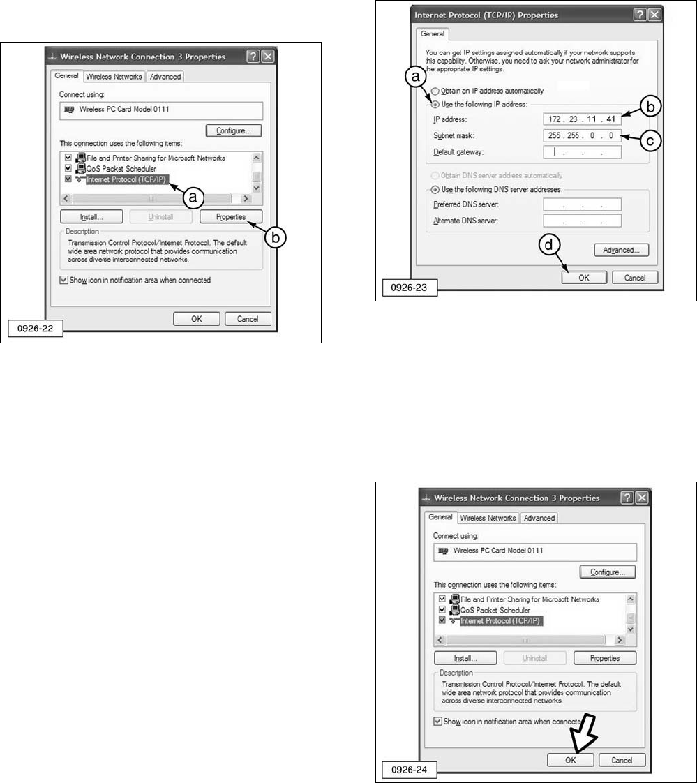
13. When the “Wireless Network Connection
Properties” screen appears:
a. Scroll down and click on “Internet
Protocol (TCP/IP)”.
b. Click “Properties”.
NOTE: Your laptop may not have as many
components as listed in the illustration.
14. Alter and record the IP Address number
by adding 10 to the third and fourth sets
of numbers of the IP address. For
example, if the number on the adapter is
172.23.1.31, the new number would be
172.23.11.41.
NOTE: The first and second sets of numbers
of the IP Address will always be 172 and 23.
The third and fourth sets of numbers in the IP
address must not be the same as any other IP
address in the local area network (LAN) or
other Wireless Communication Adapters.
Also, the numbers 0 and 255 cannot be used
for the third and fourth set of numbers. It is
highly recommended that the Network
Administrator manage all IP Addresses of
Wireless Communication Adapter modules and
PC’s configured for use with Wireless
Communication Adapters.
15. When the “Internet Protocol (TCP/IP)
Properties” screen appears:
a. Select “Use the following IP address:”.
b. Enter the altered IP Address number
from Step 14.
c. Verify that the “Subnet mask:” is
255.255.0.0.
d. Click “OK”.
16. When the “Wireless Network Connection
Properties” screen appears, click “OK”.
12
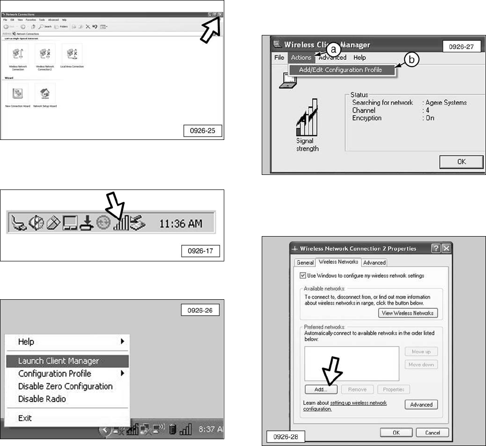
17. Close the “Network Connections” screen.
18. Right-click on the “Client Manager” icon
on the Windows taskbar.
19. Click “Launch Client Manager”.
20. Edit the configuration profile:
a. Click “Actions”.
b. Click “Add/Edit Configuration Profile”.
21. When the “Wireless Network Connection
Properties” screen appears, click on
“Add.”
13
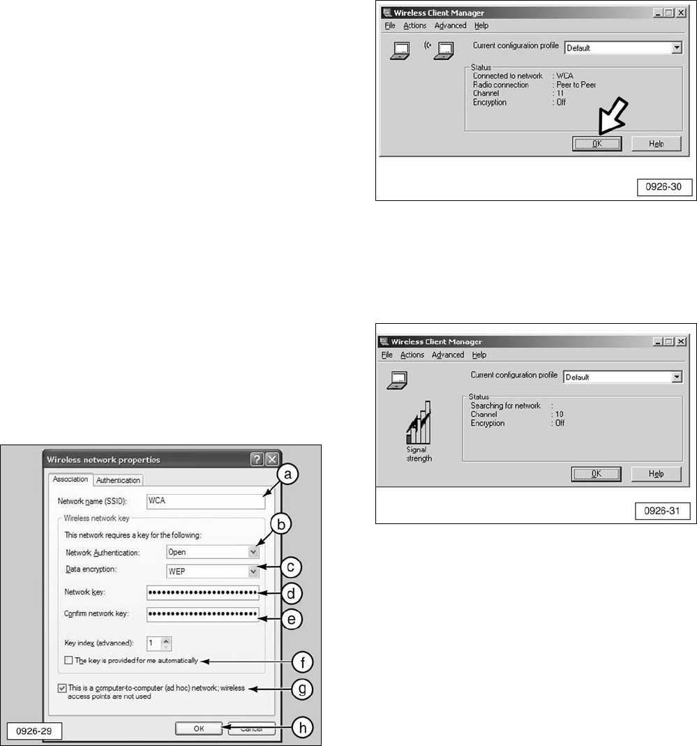
22. When the “Wireless network properties”
screen appears:
a. Type “WCA” (all capital letters) into the
“Network name (SSID):” section.
b. Select “Open” from the “Network
Authentication:” pull down menu.
c. Select “WEP” from the “Data
encryption:” pull down menu.
d. Type in the “key” (number)
35373c57222750362a334c6a71
into the “Network key:” section. Refer
to Step 22f if you are unable to type in
the number.
e. Retype the number in the “Confirm
network key” section.
NOTE: If the factory default IP Address on the
Wireless Communication Adapter has been
changed, refer to the Contact Information
section at the front of this manual.
f. If you are unable to type the “key”
(number) into the box, uncheck the
“The key is provided for me
automatically” box.
g. Check the “This is a computer-to-
computer (ad-hoc) network; wireless
access points are not used” box.
h. Click “OK”.
23. The “Wireless Client Manager” screen
should display as shown (graphic of the
two computers communicating), if the PC
Card is working properly. Click “OK” and
proceed to Step 25.
24. If the “Wireless Client Manager” screen
displays as shown, there is no network
present for communication. Make sure
the Wireless Communication Adapter and
harness are connected properly.
NOTE: If the screen (graphic of the two
computers communicating) still does not
appear, stop the installation and refer to the
Contact Information section at the front of this
manual.
14
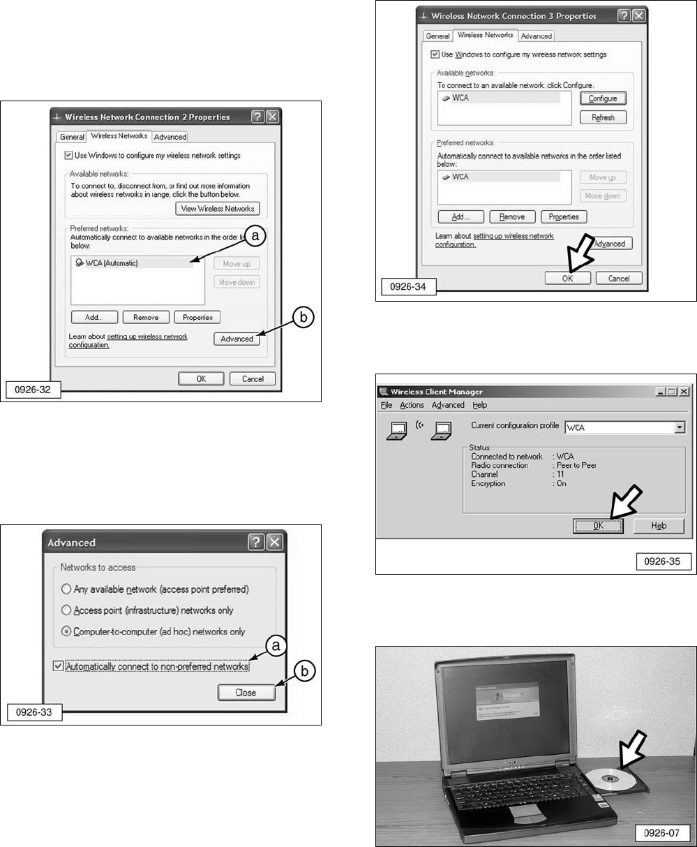
25. When the “Wireless Network Connection
Properties” screen appears:
a. “WCA” (automatic) should appear in
the “Preferred networks:” display. If
not, repeat Step 22.
b. If “WCA” does appear in the “Preferred
networks:” display, click “Advanced”.
26. When the “Advanced” screen appears:
a. Check the “Automatically connect to
non-preferred networks” box.
b. Click “Close”.
27. Click “OK” on the “Wireless Network
Connection Properties” screen.
28. The “Wireless Client Manager” screen will
display. Click “OK”.
29. Remove the Proxim Software &
Documentation CD.
15
30. Congratulations, the installation of the PC
Card is complete. Proceed to the
Configure Cat Electronic Technician
(CatET) for the Wireless Communication
Adapter section in this manual.
Windows 2000 Operating System
In order for Cat Electronic Technician (CatET)
to operate in a wireless mode, the laptop and
CatET must both be configured. This section
provides step-by-step instructions for installing
and configuring the wireless PC Card installed
in the personal computer. Refer to the section
“Configure Cat Electronic Technician for the
Wireless Communication Adapter” for step-by-
step instructions for configuring the CatET to
communicate through the Wireless
Communication Adapter (WCA).
Required Hardware and Software
In addition to these instructions, you will need
four items in order to successfully complete
the installation and configuration.
1. A laptop with a CD drive (refer to the
“System Requirements” section in this
manual for additional information).
2. A “Proxim PC Card” and software CD (part
of the tool group).
16
3. Wireless Communication Adapter.
4. CatET Version 2004B or greater software.
NOTE: Before installing the Wireless
Communication Adapter on the machine,
record the IP address which is printed on the
lower left-hand side of the adapter. The IP
address contains four sets of numbers
separated by decimal points (172.23.1.31 for
example).
Software Installation
Before starting the software installation
process, make sure Wireless Communication
Adapter (1) is connected to the machine with
wiring harness (2) provided in the tool group.
A green light in the display signifies that the
unit is correctly connected and receiving
power from the machine.
17
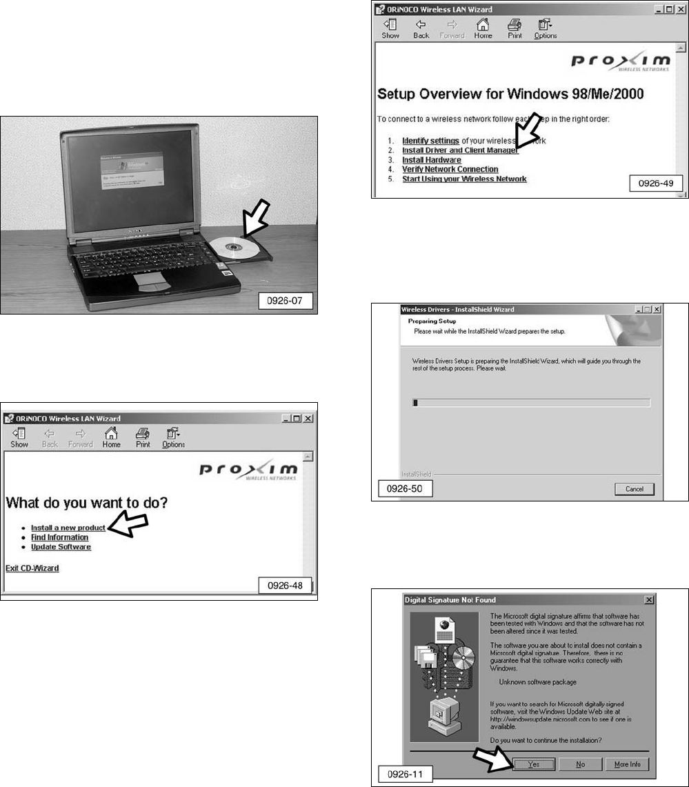
1. Insert the Proxim Software & Documentation
CD into the laptop and the Wireless LAN
Wizard will begin to run. If the CD-Wizard
does not start automatically:
a. Click the “Start” button on the Windows
task bar and select “Run”.
b. Type “d:\exsetup.exe” and click “OK”
(where d:\ represents the drive letter of
your CD-ROM drive).
2. When the “What do you want to do?”
screen appears, click on “Install a new
product”.
3. When the “Setup Overview for Windows
98/Me/2000” screen appears, click on
“Install Driver and Client Manager”.
NOTE: The “Wireless Drivers - InstallShield
Wizard” appears and shows the progress of
the installation process. This process may
take several seconds.
NOTE: The “Digital Signature Not Found”
screen may display at this time. If this screen
does display, click “Yes”.
18
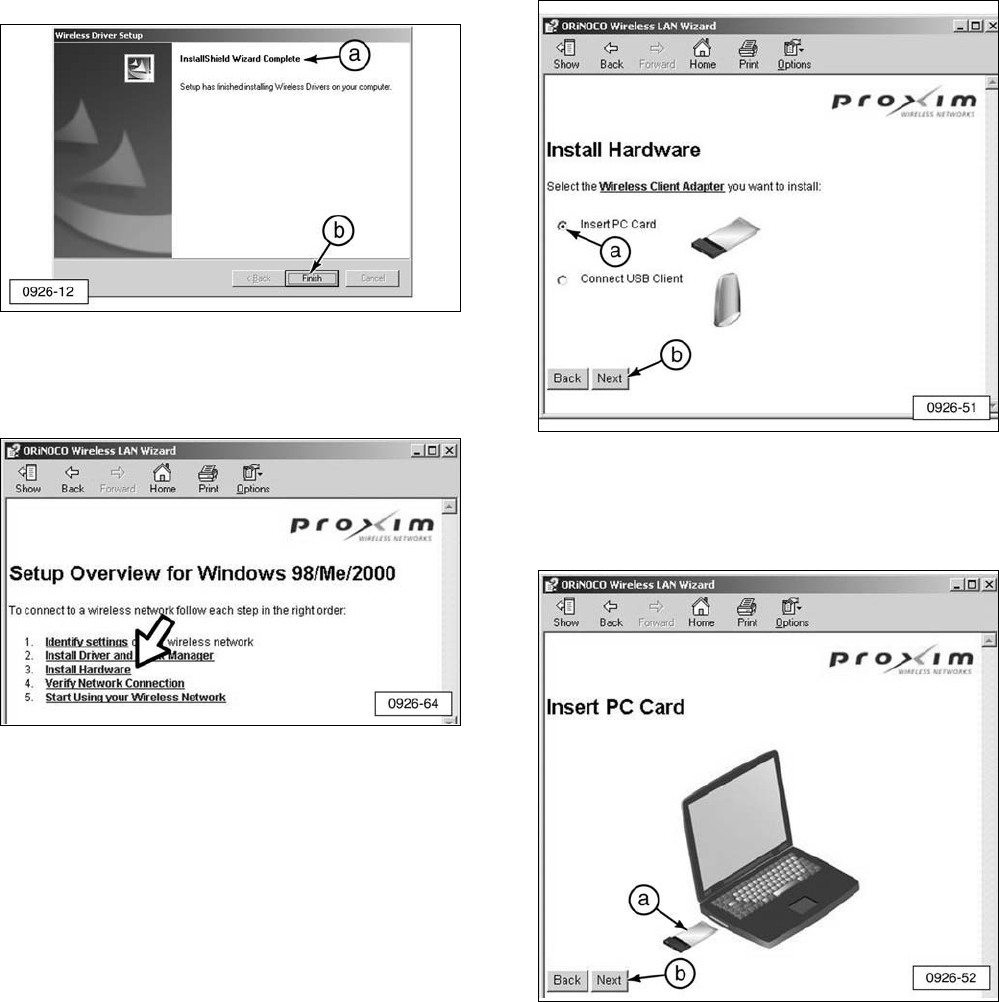
4. The “Wireless Driver Setup” screen will
appear:
a. Check the message “InstallShield
Wizard Complete” to confirm the
completion of the installation.
b. Click “Finish”.
5. The “Setup Overview for Windows
98/Me/2000” screen appears again. Click
“Install Hardware”.
6. When the “Install Hardware” screen
appears:
a. Verify that the “Insert PC Card” option is
selected.
b. Click “Next”.
7. When the “Insert PC Card” screen appears:
a. Insert the PC Card into the appropriate
card slot in the laptop computer.
b. Click “Next”.
19
NOTE: A “Found New Hardware” window
should appear in the lower right-hand corner
of the computer indicating the PC Card has
been successfully installed. If this window
does not appear, proceed to Step 10.
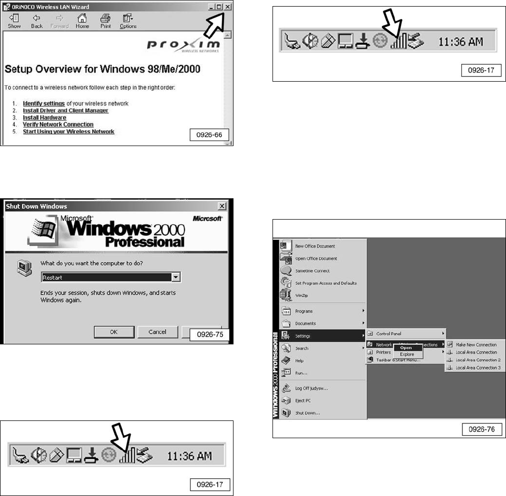
8. Close the “Setup Overview for Windows
98/ME/2000” screen.
9. Restart the computer with the PC Card
inserted.
10. If the “Client Manager” icon is visible in
the Windows Task Bar, proceed to Step
11. If the icon is not visible, open the
program using the steps below.
To manually start the Client Manager:
a. Click “Start” on the Windows taskbar.
b. Point to “Programs”.
c. Point to “Wireless”.
d. Click “Client Manager”.
e. The “Client Manager” icon should now
appear in the Windows taskbar.
11. Access the “Network Connections”
screen:
a. Click “Start” on the Windows taskbar.
b. Point to “Settings”.
c. Right-click on “Network and Dial-up
Connections”.
d. Click “Open”.
20
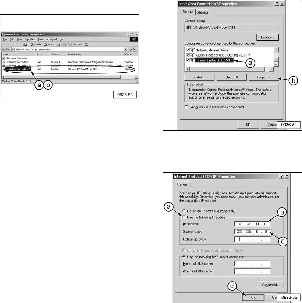
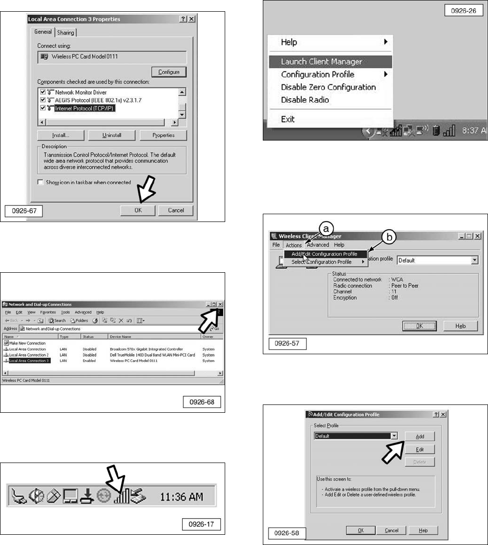
12. When the “Network and Dial-up
Connections” screen appears:
a. Right-click on the “Local Area
Connection” option that has a device
name of “Wireless PC Card Model
0111”.
b. Click “Properties”.
NOTE: If the screen does not display in the
“Details” view as shown, click on the Views
icon and click “Details”.
13. Alter and record the IP Address number
by adding 10 to the third and fourth sets
of numbers of the IP address. For
example, if the number on the adapter is
172.23.1.31, the new number would be
172.23.11.41.
NOTE: The first and second sets of numbers
of the IP Address will always be 172 and 23.
The third and fourth sets of numbers in the IP
address must not be the same as any other IP
address in the local area network (LAN) or
other Wireless Communication Adapters.
Also, the numbers 0 and 255 cannot be used
for the third and fourth set of numbers. It is
highly recommended that the Network
Administrator manage all IP Addresses of
Wireless Communication Adapter modules and
PC’s configured for use with Wireless
Communication Adapters.
NOTE: If the factory default IP Address on the
Wireless Communication Adapter has been
changed, refer to the Contact Information
section at the front of this manual.
14. When the “Local Area Connection
Properties” screen appears:
a. Scroll down and click on “Internet
Protocol (TCP/IP)” option.
b. Click “Properties”.
15. When the “Internet Protocol (TCP/IP)
Properties” screen appears:
a. Select “Use the following IP address:”.
b. Enter the altered IP Address number
from Step 13.
c. Verify that the “Subnet mask:” is
255.255.0.0.
d. Click “OK”.
21
16. When the “Local Area Connection
Properties” screen appears, click “OK”.
17. Close the “Network and Dial-up
Connections” screen.
18. Right click on the “Client Manager” icon
on the Windows taskbar.
19. Click “Launch Client Manager”.
20. Edit the configuration profile:
a. Click “Actions”.
b. Click “Add/Edit Configuration Profile”.
21. When the “Add/Edit Configuration Profile”
screen appears, click on “Add”.
22
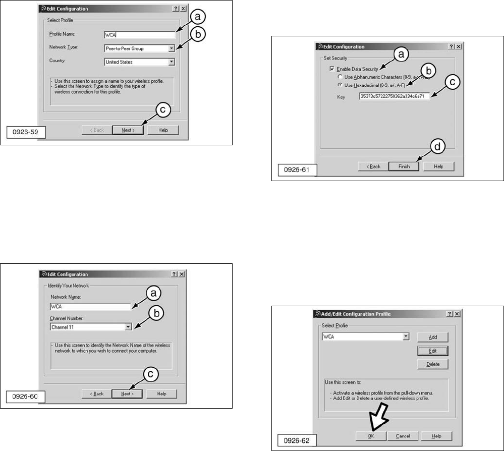
22. When the “Edit Configuration” screen
appears:
a. Type any name/identifier into “Profile
Name” area.
b. Select “Peer-to-Peer Group” from the
“Network Type” pull down menu.
c. Click “Next”.
23. A second “Edit Configuration” screen will
appear:
a. Type “WCA” in “Network Name:”.
b. Select “Channel 11” from the “Channel
Number” pull-down menu.
c. Click “Next”.
24. A third “Edit Configuration” screen will
appear:
a. Select “Enable Data Security”.
b. Select “Use Hexadecimal”.
c. Type in the “Key” (number)
35373c57222750362a334c6a71
into the “Key” section.
d. Click “Finish”.
NOTE: If the factory default IP Address on the
Wireless Communication Adapter has been
changed, refer to the Contact Information
section at the front of this manual.
25. A fourth “Add/Edit Configuration Profile”
screen will appear. Click “OK”.
23
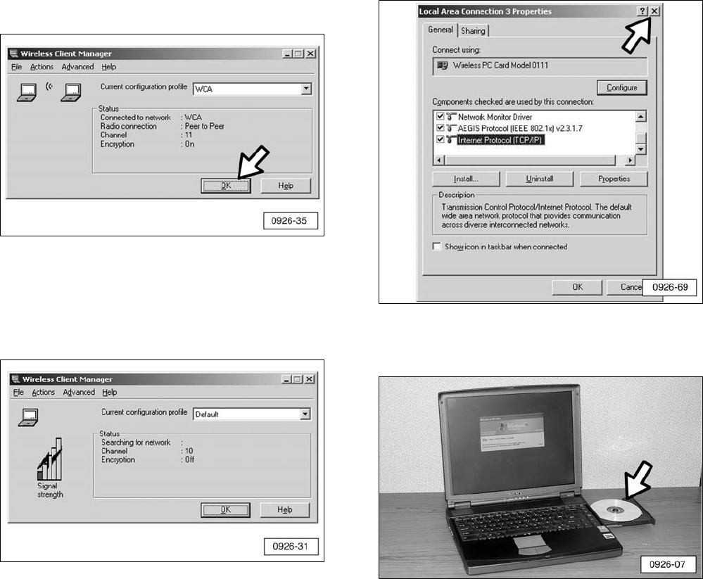
26. The “Wireless Client Manager” screen
should display as shown (graphic of the
two computers communicating), if the PC
Card is working properly. Click “OK”.
27. If the “Wireless Client Manager” screen
displays as shown, there is no network
present for communication. Make sure
the Wireless Communication Adapter and
harness are connected properly.
NOTE: If the screen (graphic of the two
computers communicating) still does not
appear, stop the installation and refer to the
Contact Information section at the front of this
manual.
28. Close the “Local Area Connection
Properties” screen.
29. Remove the Proxim Software &
Documentation CD.
30. Congratulations, the installation of the PC
Card is complete. Proceed to the
“Configure Cat Electronic Technician
(CatET) for the Wireless Communication
Adapter” section in this manual.
24
Configure Cat Electronic
Technician for the Wireless
Communication Adapter
1. Open CatET.
NOTE: The minimum version of CatET software
is 2004B or greater.
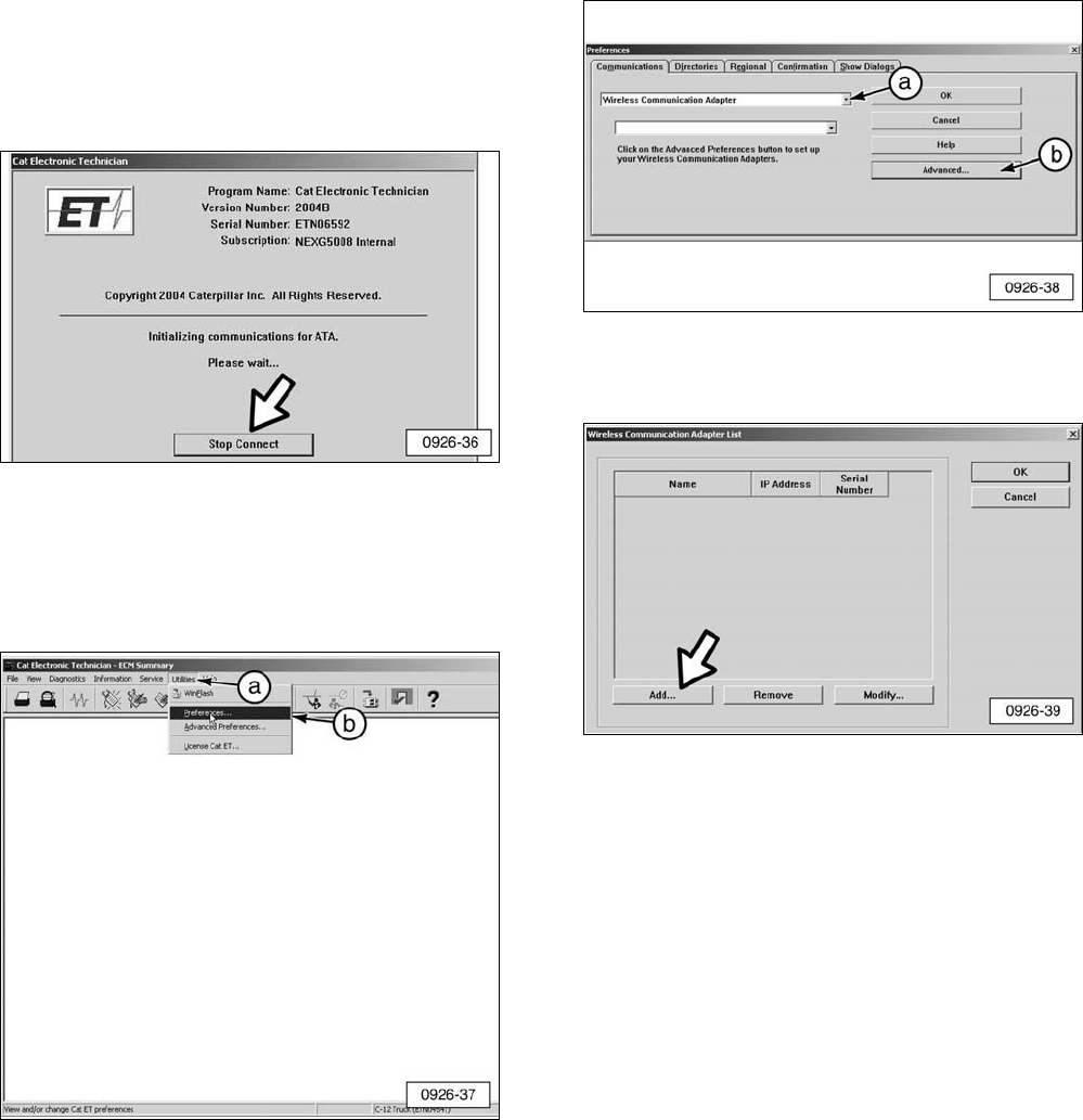
2. The “Cat Electronic Technician” screen
should appear on all new installations.
Click “Stop Connect”.
3. From the “Cat Electronic Technician”
screen:
a. Click “Utilities”.
b. Then “Preferences”.
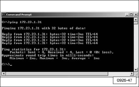
4. From the “Preferences” screen:
a. Select the “Wireless Communication
Adapter” option from the pull-down
menu.
b. Click “Advanced”.
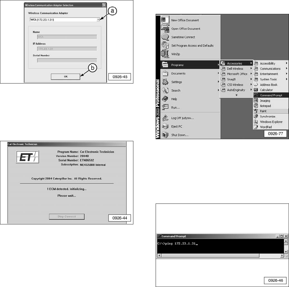
5. When the the “Wireless Communication
Adapter List” screen appears, click “Add”.
25
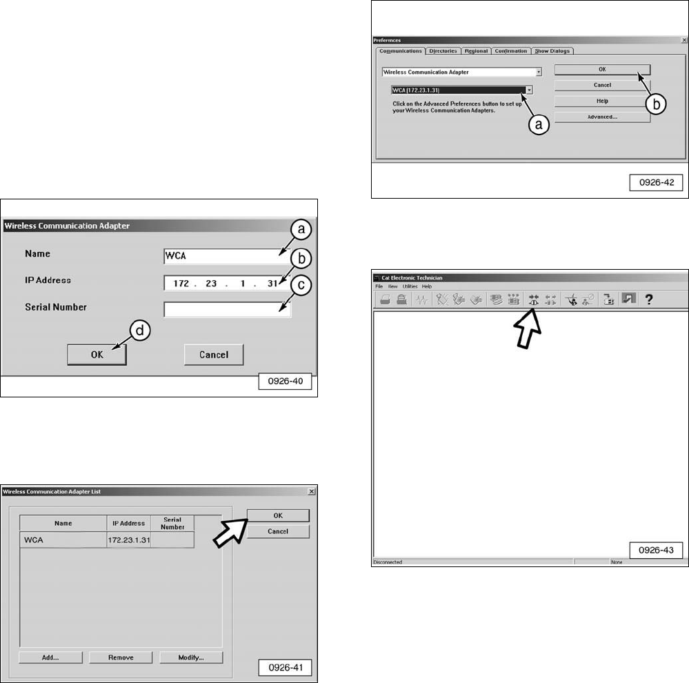
6. When the “Wireless Communication
Adapter” screen appears:
a. Type “WCA” (in all capital letters) in
“Name” (or a more descriptive name as
desired).
b. Type the IP Address for the Wireless
Communication Adapter in the “IP
Address” field. (Note: This IP address
comes from the label on the wireless
communication adapter. It must be
entered exactly as printed on the
label).
c. Enter “Serial Number” of Wireless
Communication Adapter if desired
(optional).
d. Click “OK”.
7. Make sure the “Wireless Communication
Adapter List” appears with the information
just entered, then click “OK”.
8. When the “Preferences” screen appears:
a. Select the name and IP address for
Wireless Communication Adapter from
the pull-down lists.
b. Click “OK”.
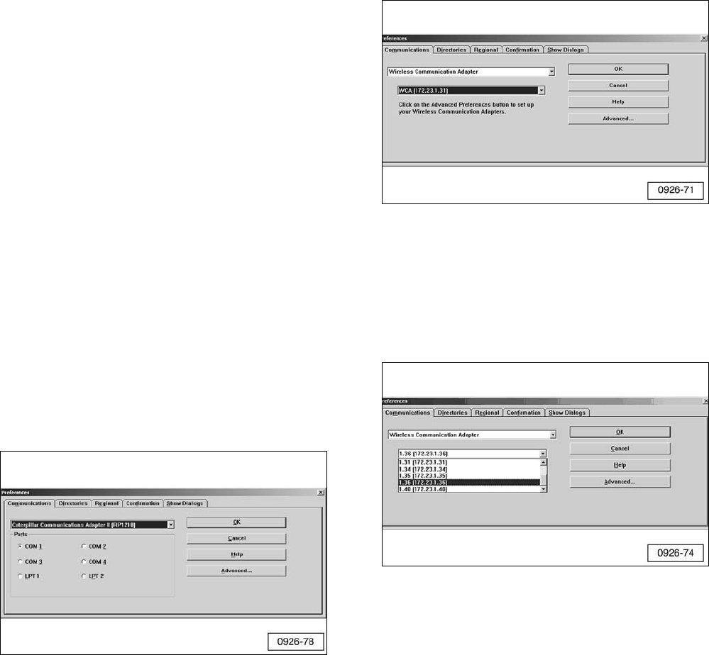
9. When the main ”CatET” screen appears,
click the “Connect” icon.
26
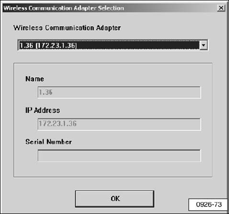
10. When the “Wireless Communication
Adapter Selection” screen appears:
a. Make sure the WCA with the correct IP
address is in the “Wireless
Communication Adapter” field.
b. Click “OK”.
11. The following screen should display if the
Wireless Communication Adapter is
working correctly. The Wireless
Communication Adapter is now installed
and ready to communicate with the laptop
computer.
NOTE: If this screen does not display, go to
the next step.
12. Test to make sure the wireless networks
are communicating.
a. Click on the “Start” button in the
Windows taskbar.
b. Point to “Programs”.
c. Point to “Accessories”.
d. Click on “Command Prompt”.
13. The “Command Prompt” window will
display.
a. Type “ping 172.23.1.31” (the IP
address on the Wireless
Communication Adapter).
b. Press “Enter” key on the keyboard.
27
14. In response, “Reply from 172.23.1.31”
messages should display. The IP number
should match the IP address printed on
the Wireless Communication Adapter.
15. If the “Reply from” messages do not
display, repeat the entire installation
procedure. If the “Reply from” messages
still do not appear, refer to the Contact
Information at the front of this manual.
16. If the “Reply from” screen is displayed as
shown above, go to Step 1 of this
procedure (Configure Cat Electronic
Technician for the Wireless
Communication Adapter) and verify the IP
address of the Communication Adapter
you are trying to connect is correct in
CatET. If communication still does not
occur, refer to the Contact Information at
the front of this manual.
Using the Wireless
Communication Adapter
When using the Wireless Communication
Adapter to do remote monitoring of machines,
there are several factors that can have a
significant affect on overall performance of the
system.
1. Location of the Wireless Communication
Adapter on the machine.
2. Location of the PC that will be
communicating with the Wireless
Communication Adapter.
3. Obstacles in the Line-of-Sight between the
PC and the Wireless Communication
Adapter.
4. Weather conditions.
The Wireless Communication Adapter should
be located as high up on the machine as
possible, preferably with the antenna at the
highest point of the machine and adjusted to
point up into the air. Since the Wireless
Communication Adapter relies on
Line-of-Sight for effective communications, it is
important to place the device in a location that
can be easily seen from the location of the PC
that will be monitoring it.
The location of the PC used to monitor the
machine is just as important. If the PC is
sitting on the seat of the service truck, it will be
much less effective in communicating with the
Wireless Communication Adapter than it would
be if it were outside the vehicle in “Line-of-
Site” of the machine. An optional Range
Extender Antenna (see Optional Accessories)
will provide extended range and permit the PC
to be operated where it is not in Line-of-Sight
of the Wireless Communication Adapter, as
long as the Range Extender Antenna can see
the device from its location.
28
Obstacles in the Line-of-Sight between the PC
and the Wireless Communication Adapter can
have a significant affect on the range of the
system. Obstacles may include hills,
buildings, or even the machine being
monitored. If the machine being monitored
drives over a hill, radio communication with the
PC will likely stop until the machine is visible.
Operating the machine with buildings or other
machines in the Line-of-Sight will likely deliver
similar reduction or loss of radio
communication. The machine itself can also
be an obstacle if the Wireless Communication
Adapter is placed on the right side of the
machine and the PC that is monitoring the
machine is on the left. In some cases, while
communication is not completely lost, the
range of the system will be significantly
reduced.
Another factor that can reduce the range of
the Wireless Communication Adapter system is
weather. Range of the system is best on clear,
dry days. Rain and fog will reduce the range
of the system, but will not keep the system
from operating.
It is important to follow these guidelines in
order to achieve the best possible results
when using the Wireless Communication
Adapter.
1. Start CatET and click on “Utilities”, then
“Preferences” on the menu bar to select the
type of Communication Adapter to be used.
This will bring up the following screen.
2. Click on the down arrow to select the
Communication Adapter type. From the list
that is displayed, select “Wireless
Communication Adapter”. When this
selection is made, a second select list will
be displayed that allows the user to select
the Wireless Communication Adapter that is
to be used.
3. If a site has multiple Wireless
Communication Adapter modules, they can
be added through the “Advanced” button
of this menu. The following screen shows a
window that displays several Wireless
Communication Adapters that have been
configured.
29
4. Select the appropriate interface and click
on “OK”. Click on the “Connect” icon to
attempt a connection to the selected
Wireless Communication Adapter. CatET
will display the following window asking you
to verify the selected Wireless
Communication Adapter. If correct, click on
“OK” and CatET will attempt a connection.
If it is not correct, click on the down arrow
of the Wireless Communication Adapter
and select the correct adapter.
NOTE:The following screen is also displayed
upon CatET startup when the last selected
Communication Adapter was Wireless
Communication Adapter.
5. Once the Wireless Communication Adapter
has been selected as the type of
Communication Adapter to be used
(Utilities/Preferences), CatET will try to
connect using Wireless Communication
Adapter on startup of the application. In
order to select a different Communication
Adapter, it is necessary for the user to
“Stop Connect” (or let the connection time
out) and click on “Utilities” then
“Preferences”. Click on the desired
Communication Adapter and click on “OK”.
Troubleshooting
General Troubleshooting
Information
Many of the problems that can prevent correct
operation of the Wireless Communication
Adapter are related to Wireless Networking
issues. Some of these problems are related to
initial configuration of the 802.11b Enabled PC
while others are related to issues that may be
seen as part of typical operation during use of
the product. The following section outlines
some of the error messages that are related to
the Wireless Communication Adapter, what
can cause these messages, and how to isolate
and correct the problems.
Service Tools
There are no special service tools required
other than the tools that are included as part of
the Windows operating system or those that
are installed as part of the Wireless
Communication Adapter software installation
process. The tools used are: Windows
Internet Explorer, Windows Command Prompt,
and Proxim Wireless Client Manager.
Diagnostic Procedures
Most problems are found when the Service
Technician runs Caterpillar Electronic
Technician (CatET) and attempts to connect to
a particular Wireless Communication Adapter.
If there are problems establishing this
connection, CatET will provide an error
message indicating the type of problem that
was encountered. This section describes
specific error messages related to the Wireless
Communication Adapter, possible causes, and
how to isolate the source of the problem.
30
Troubleshooting with Error Codes
Error #142
Problem - The interface hardware is not
connected.
Solution - Connect the hardware.
Error #142
Problem - This error code indicates that the
interface hardware is not responding. This is
an error code that applies primarily to the
“Wired” Communication Adapters that connect
to the Serial or USB ports of the Service Tool
Computer.
Solution - In CatET, click on “Utilities”, then
click on “Preferences”. Make sure that the
Wireless Communication Adapter is selected
as the type of Communication Adapter being
used.
Error #901
Problem – Check Wireless Communication
Adapter Address and Power – Connection
Timed Out.
Cause
1.Incorrect Wireless Communication Adapter
Selected.
2. Selected Wireless Communication Adapter
not powered.
3. Selected Wireless Communication Adapter
out of range.
4. 802.11b radio disabled in Wireless Client
Manager.
5. Incorrect WEP Encryption Key
(configuration).
Solution
1. Check the IP Address on the label of the
Wireless Communication Adapter that you
are trying to connect to and ensure that the
correct IP Address is selected on the CatET
Wireless Communication Adapter Selection
screen.
2. Ensure the Wireless Communication
Adapter is powered up (green LED ON)
and in range of the 802.11b Enabled PC.
3. Re-check the connection with CatET. If
communication is established,
troubleshooting is complete. If not,
continue to Step 4.
4. The radio may be disabled in the Wireless
Client Manager. To check this, open the
Wireless Client Manager by clicking on
“Start”, then “Programs”, then “Wireless”,
then “Client Manager”. In the Wireless
Client Manager, click on “File” on the menu
bar. If the first entry is “Enable Radio”, then
the radio is currently disabled. Click on
“Enable Radio” to re-enable the 802.11b
radio functionality.
5. Re-check the connection with CatET. If
communication is established,
troubleshooting is complete. If not,
continue to Step 6.
6If this PC has never successfully
communicated with a Wireless
Communication Adapter, it is likely a
configuration issue involving the WEP
Encryption Key in the 802.11b Enabled PC.
Refer to installation documents to verify the
configuration settings of the 802.11b
Enabled PC.
7. Re-check the connection with CatET. If
communication is established,
troubleshooting is complete. If not, refer to
the Contact Information at the front of this
manual.
Error #902
Problem – Check PC Wireless Adapter
Address Setup – No Route to Host (10065)
Cause
1. 802.11b Wireless Network Interface Card is
not installed.
2. Windows Network Interface (for 802.11b
card) is disabled
3. Windows Network Interface definition (for
802.11b card) is incorrect (configuration)
Solution
1. Verify the 802.11b card is installed in
(plugged into) the computer. If not, install
the card. If it is installed correctly, continue
to Step 2.
31

2. Verify the 802.11b drivers have been
installed. To do this, open the Wireless
Client Manager by Clicking on “Start”, then
“Programs”, then “Wireless”, then “Client
Manager”. In the Wireless Client Manager,
click on “Advanced” on the menu bar, then
click on “Card Diagnostics”. All “Self Test”
results should indicate “OK” if driver is
installed correctly. If driver is not installed
correctly, repeat installation procedure for
the 802.11b PC card. If the driver is
installed correctly, continue to Step 3.
3. Verify the “Windows Network Interface” is
enabled. To do this, click on “Start”,
“Settings”, then right-click on “Network and
Dial-Up Connections” and click on “Open”.
Right-click on the “Local Area Connection”
that corresponds to the device “Wireless
PC Card Model 0111”. If the status is
“Disabled”, click on “Enable” to enable the
Network Interface Card for the Wireless
Communication Adapter.
4. Re-check the connection with CatET. If
communication is established,
troubleshooting is complete. If not,
continue to Step 5.
5. Verify the Network Configuration settings on
the 802.11b Enabled PC are correct. Refer
to the installation procedure for the 802.11b
PC card and verify that the IP Address and
Subnet Mask settings are correct.
6. Re-check the connection with CatET. If
communication is established,
troubleshooting is complete. If not, refer to
the Contact Information section at the front
of this manual.
Troubleshooting Symptoms
Symptom
One or more network applications don’t work
when wireless card is enabled.
Possible Cause
If a network application uses an IP Address
that resides in the address range reserved for
Wireless Communication Adapter, Windows
will try to “route” messages intended for that
network application across the wireless
network. Communications with that network
application will fail whenever the card is
enabled.
Solution
To verify whether or not this is the cause of the
problem, disable your 802.11b card and see if
the network application problem still exists.
Disable the card by:
1. Click on “Start”, “Settings”.
2. Right-click on “Network and Dial-Up
Connections”.
3. Click on “Open”.
4. Right-click on the “Local Area Connection”
that corresponds to the device “Wireless
PC Card Model 0111”.
5. Click on “Disable” to disable the Network
Interface Card for the Wireless
Communication Adapter. If the network
application starts working again, check with
the Network Administrator to consider
possible IP Address changes (of the
Wireless Communication Adapter) to
resolve the conflict.
©2005 Caterpillar NEHS0926-01
All Rights Reserved Printed in U.S.A.
For information on service tools or shop supplies,
contact Dealer Service Tools on:
Dealer Service Tools
501 S.W. Jefferson
Peoria, IL U.S.A. 61630-2125
U.S.A.: 1-800-542-8665
Illinois: 1-800-541-8665
Canada: 1-800-523-8665
World: 1-309-675-6277
Fax: 1-309-494-1475
CSTG_Hotline@cat.com
Wireless Communication Adapter Regulatory Information
*Interference Statement*
FCC ID: PQMWCA1
IC: 4071A-WCA1
This device complies with Part 15 of the FCC Rules and with RSS-210 of Industry Canada.
Operation is subject to the following two conditions: (1) this device may not cause harmful
interference, and (2) this device must accept any interference received, including interference that
may cause undesired operation.
Warning: Changes or modifications not expressively approved by the party responsible for
compliance could void the user’s authority to operate the equipment.
The term “IC:” before the radio certification number only signifies that Industry Canada technical
specifications were met.
*Other Information*
The device and its antenna and must not be co-located or operating in conjunction with any other
antenna or transmitter.
When this device is installed either as a fixed-mount or mobile application there is a minimum
required separation distance of 20 cm from users.