Ceragon Networks IP20S24 IP-20 all outdoor unit User Manual Installation and User Guide for FibeAir IP 20S
Ceragon Networks Ltd. IP-20 all outdoor unit Installation and User Guide for FibeAir IP 20S
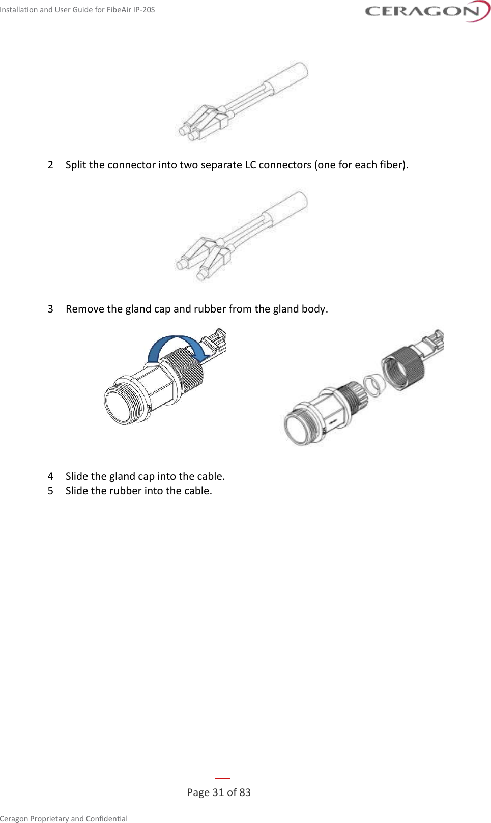
UserManual.wiki
>
Ceragon Networks
>
IP20S24 User Manual
Users Manual
Navigation menu
Upload a User Manual
Namespaces
Wiki Guide
HTML
PDF
Info
Views
User Manual
Discussion / Help
Navigation
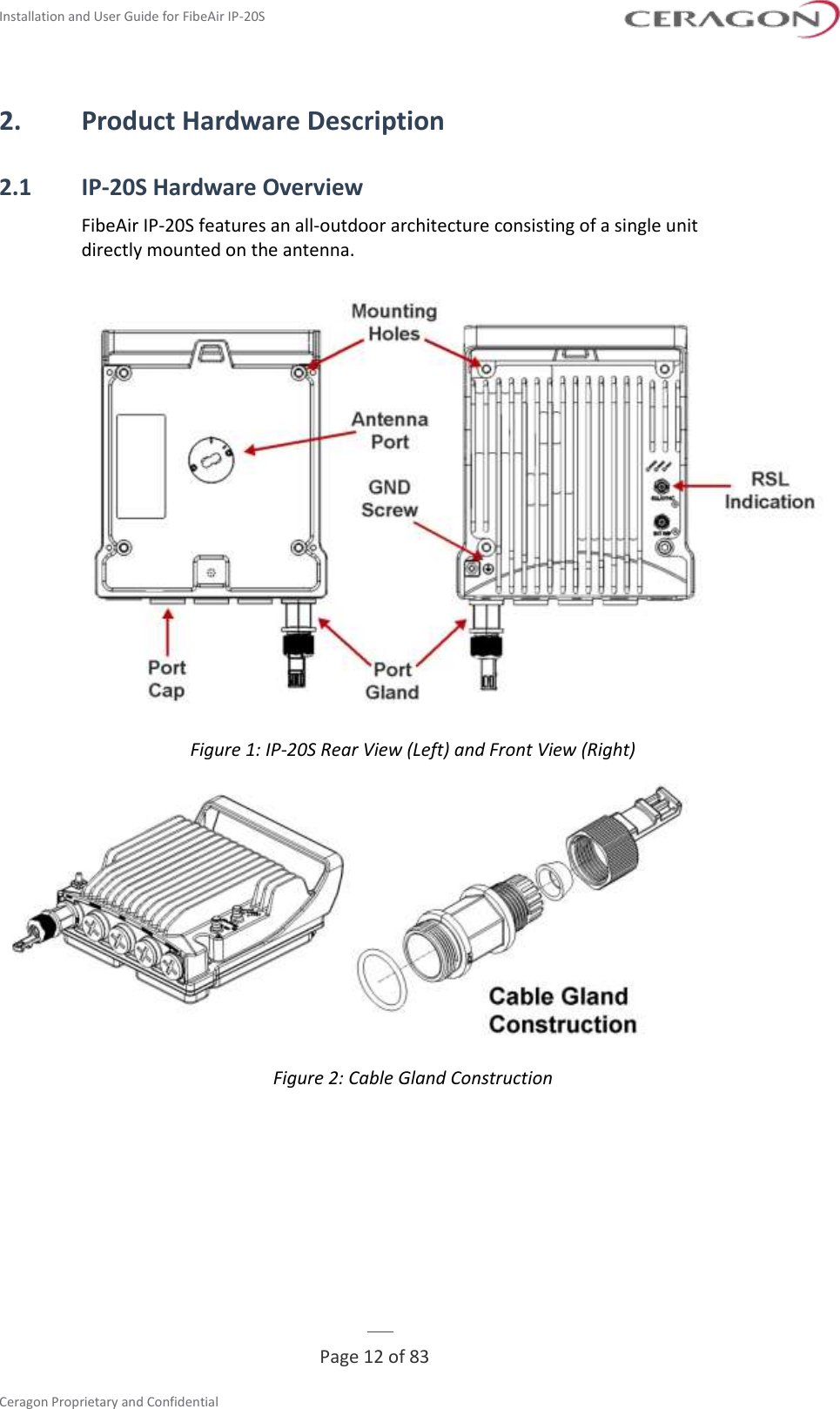
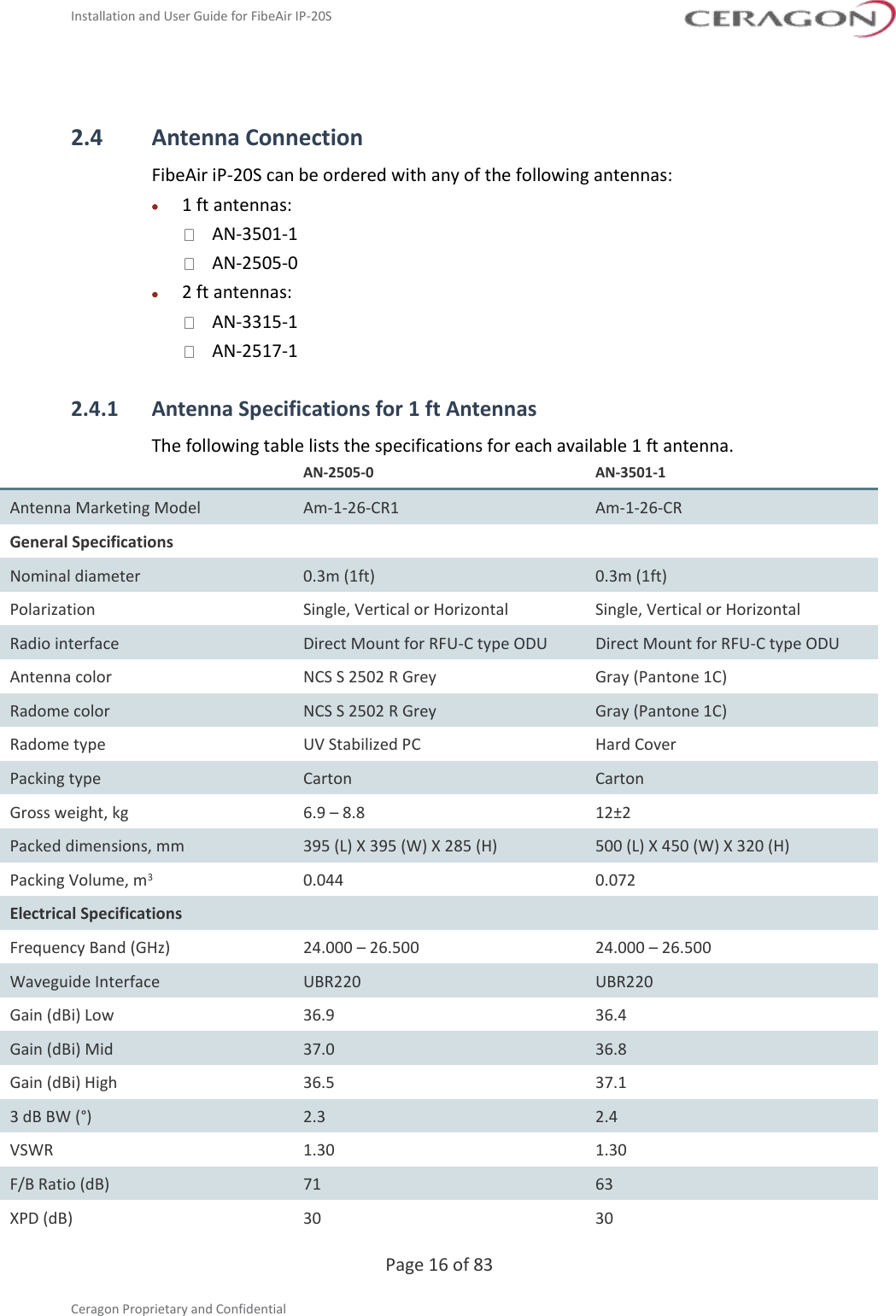
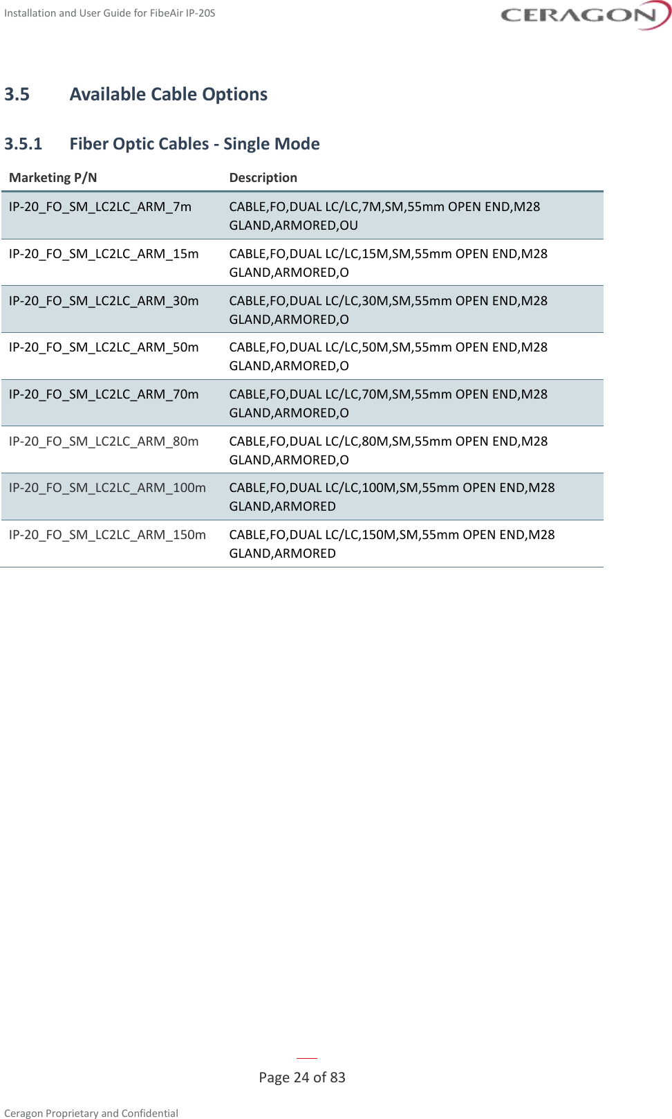
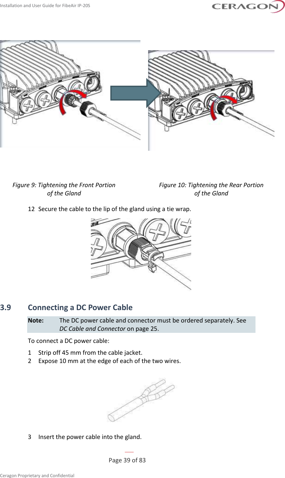
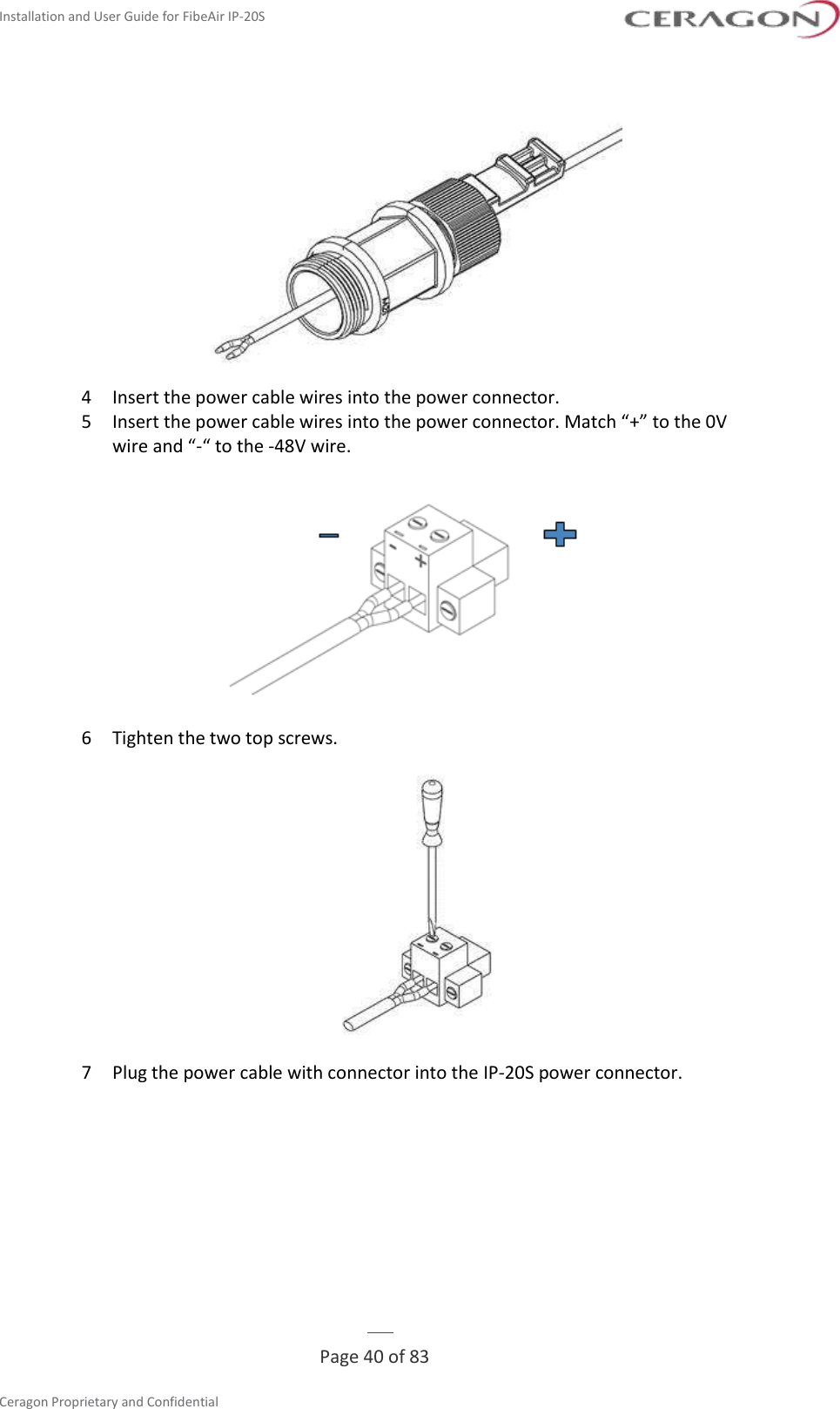
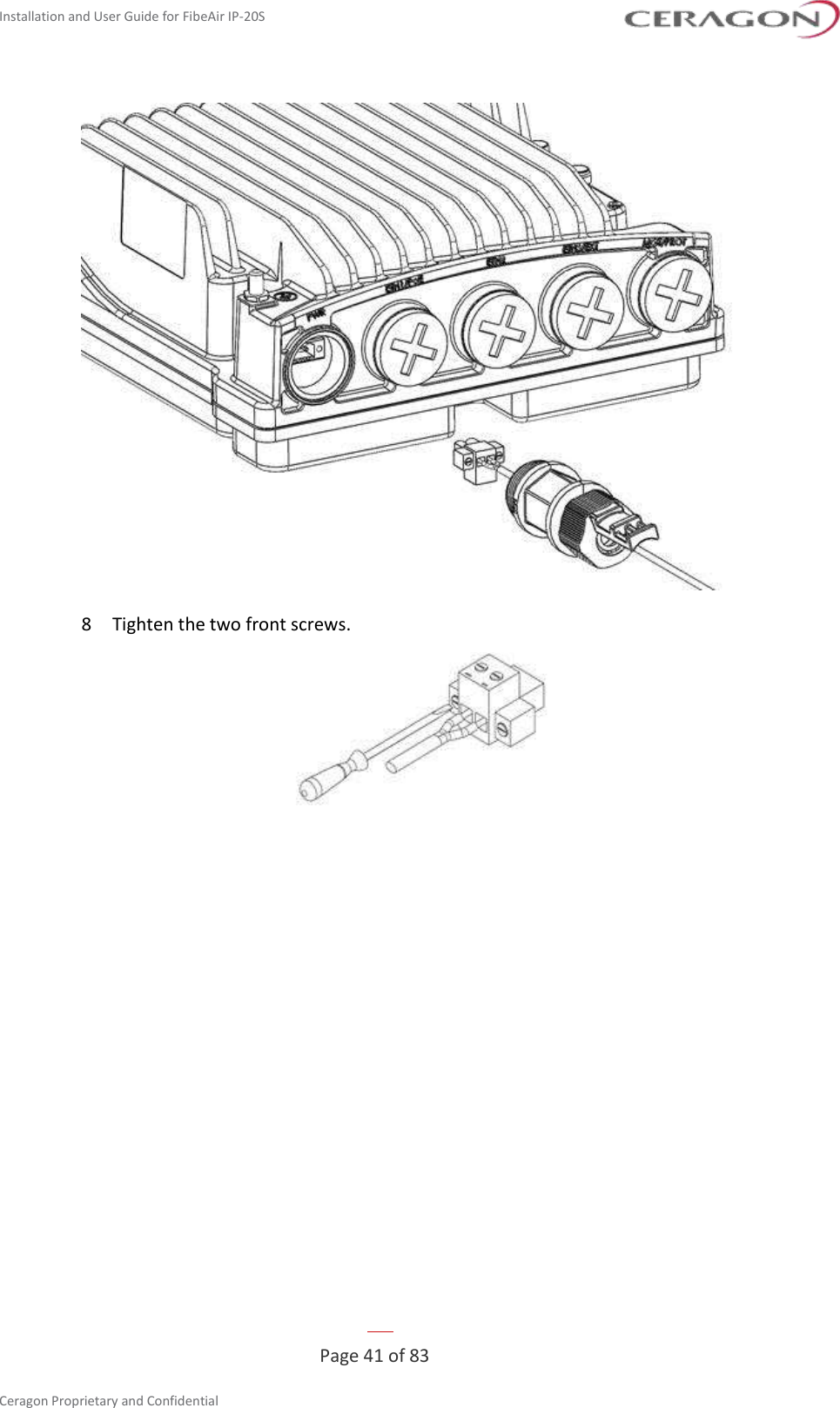
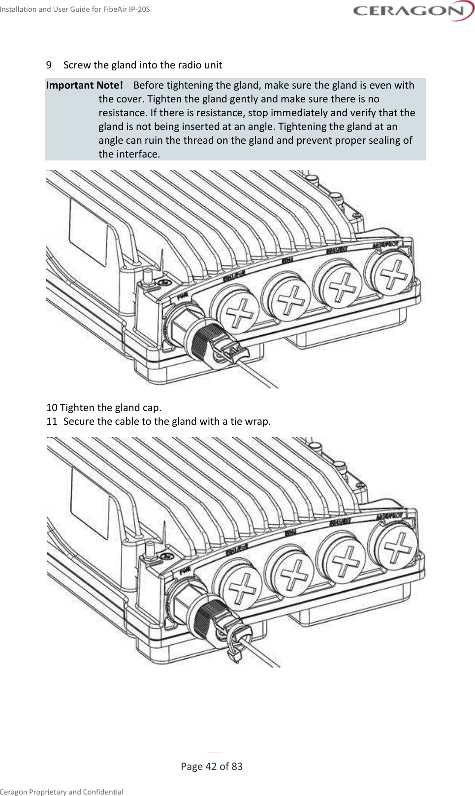
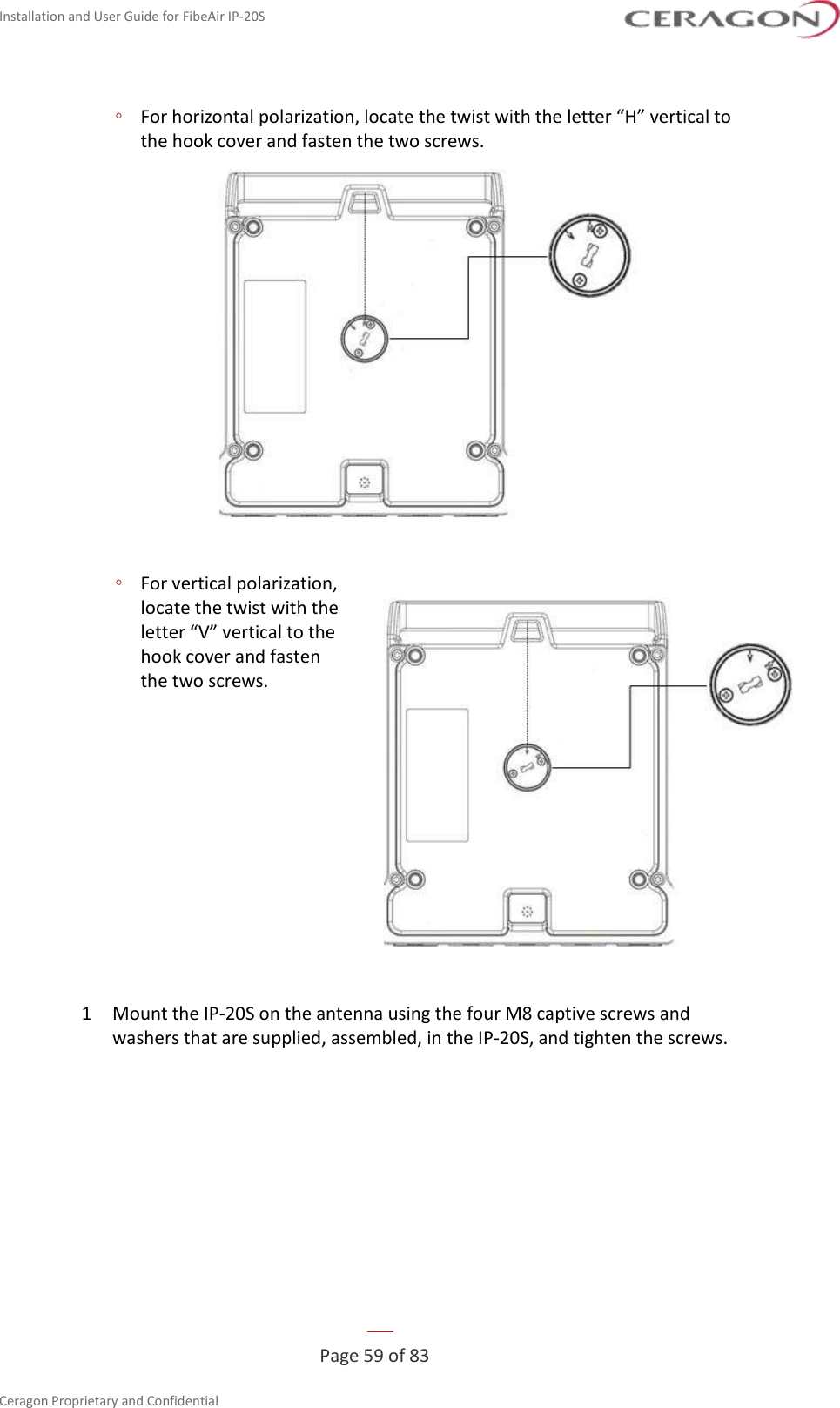
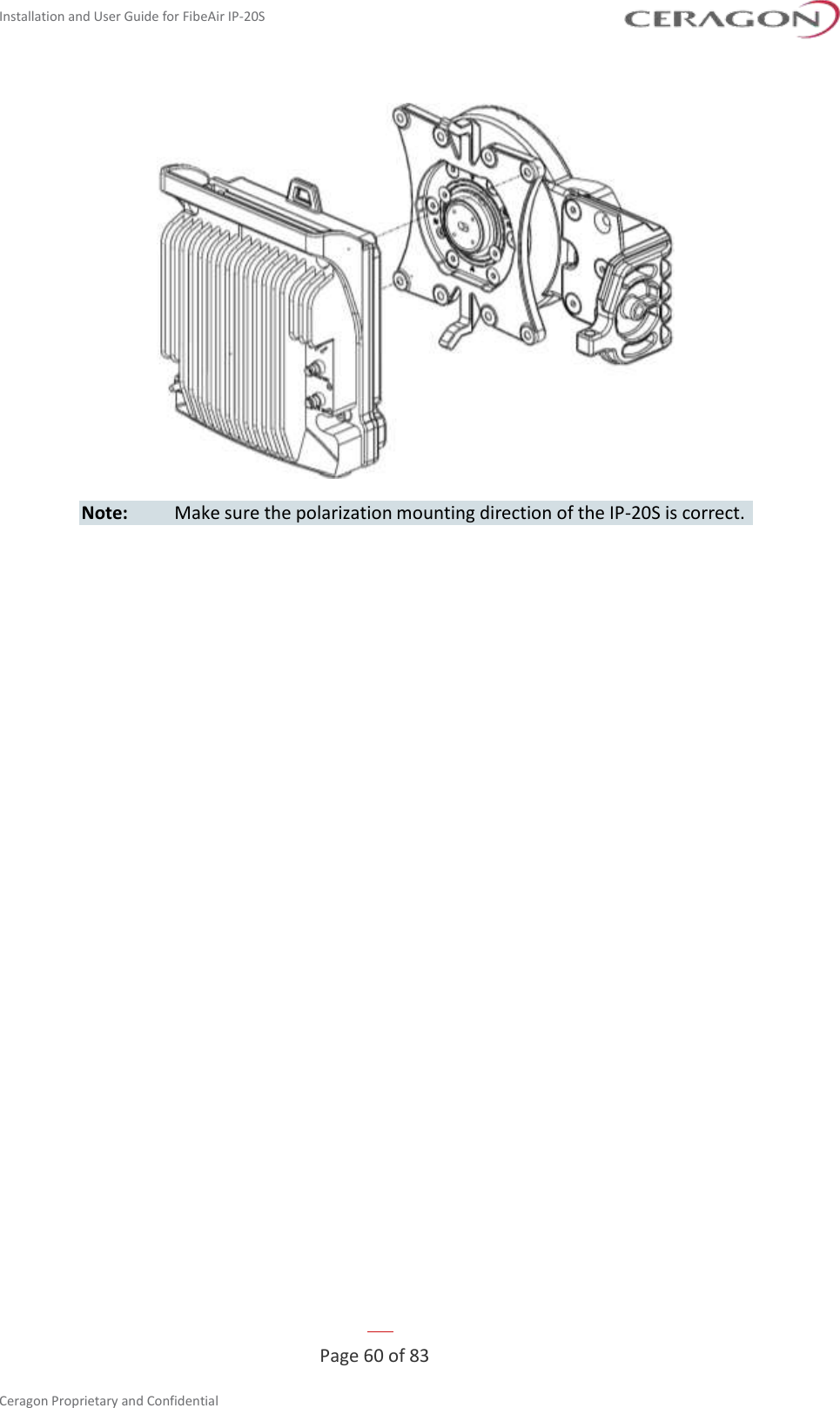
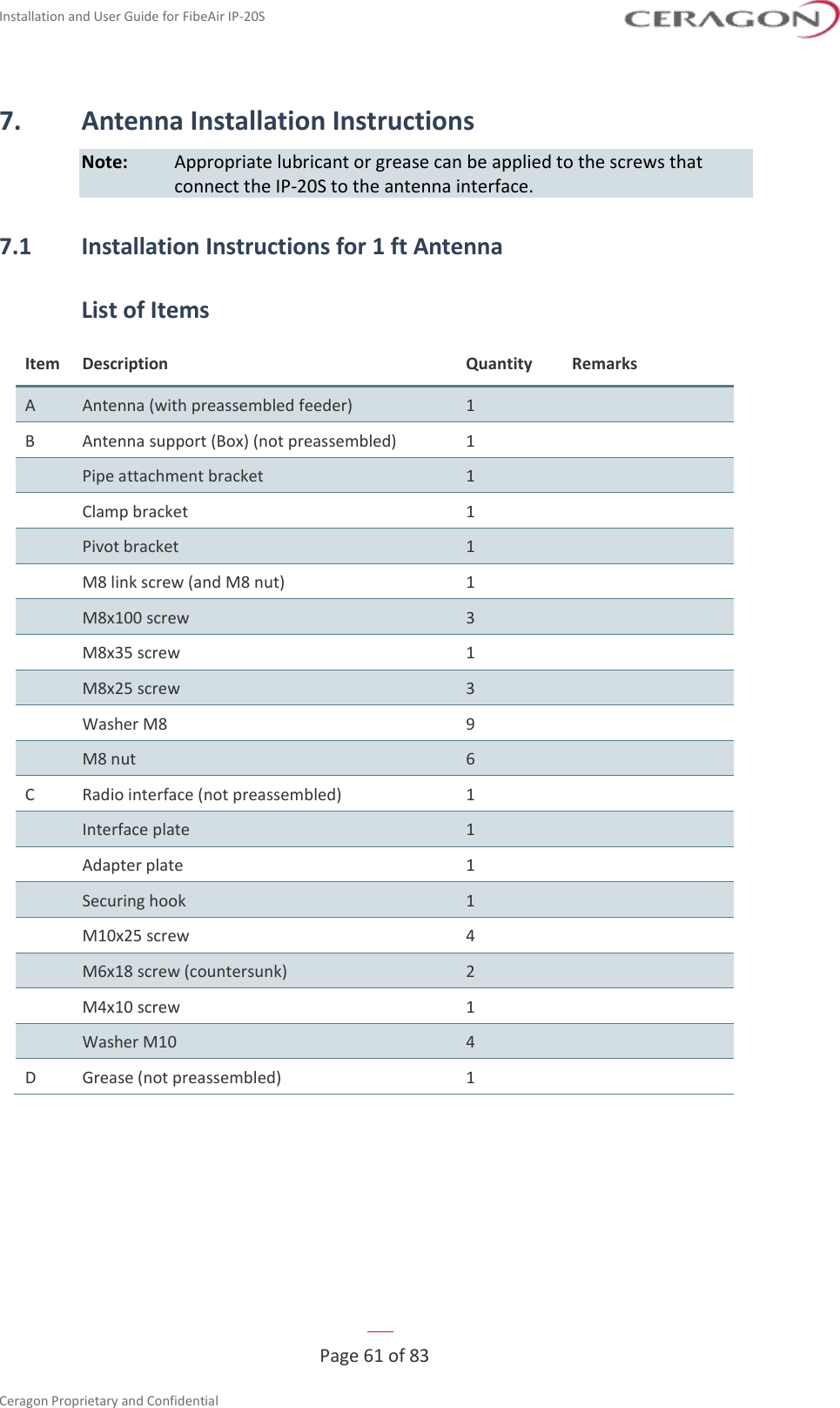
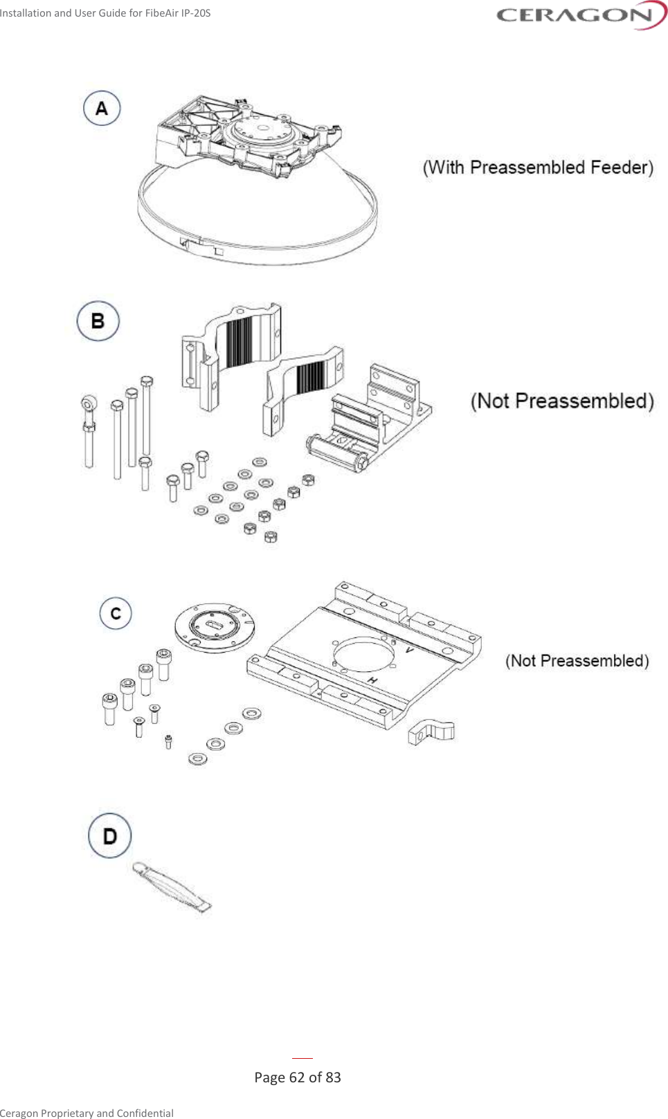
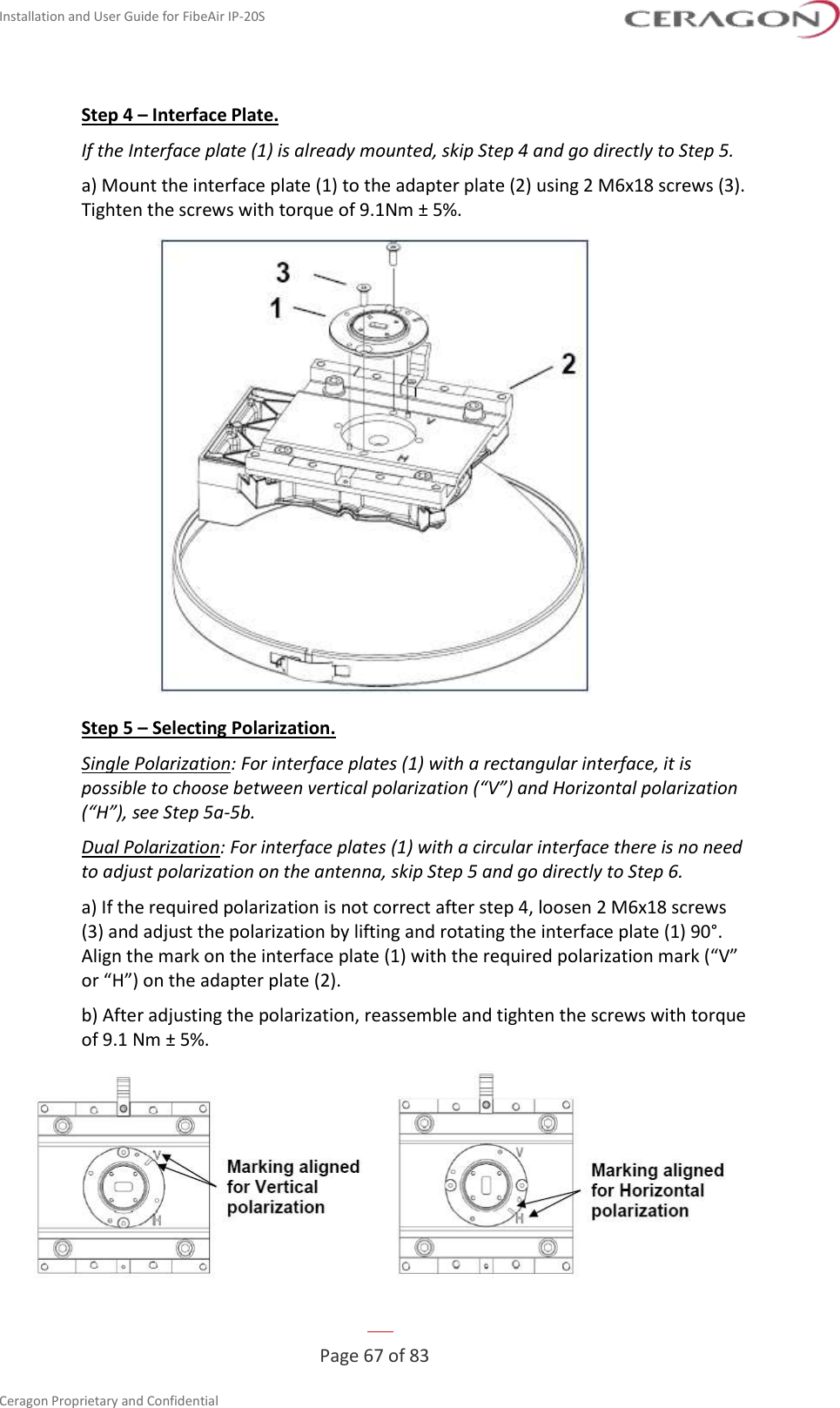
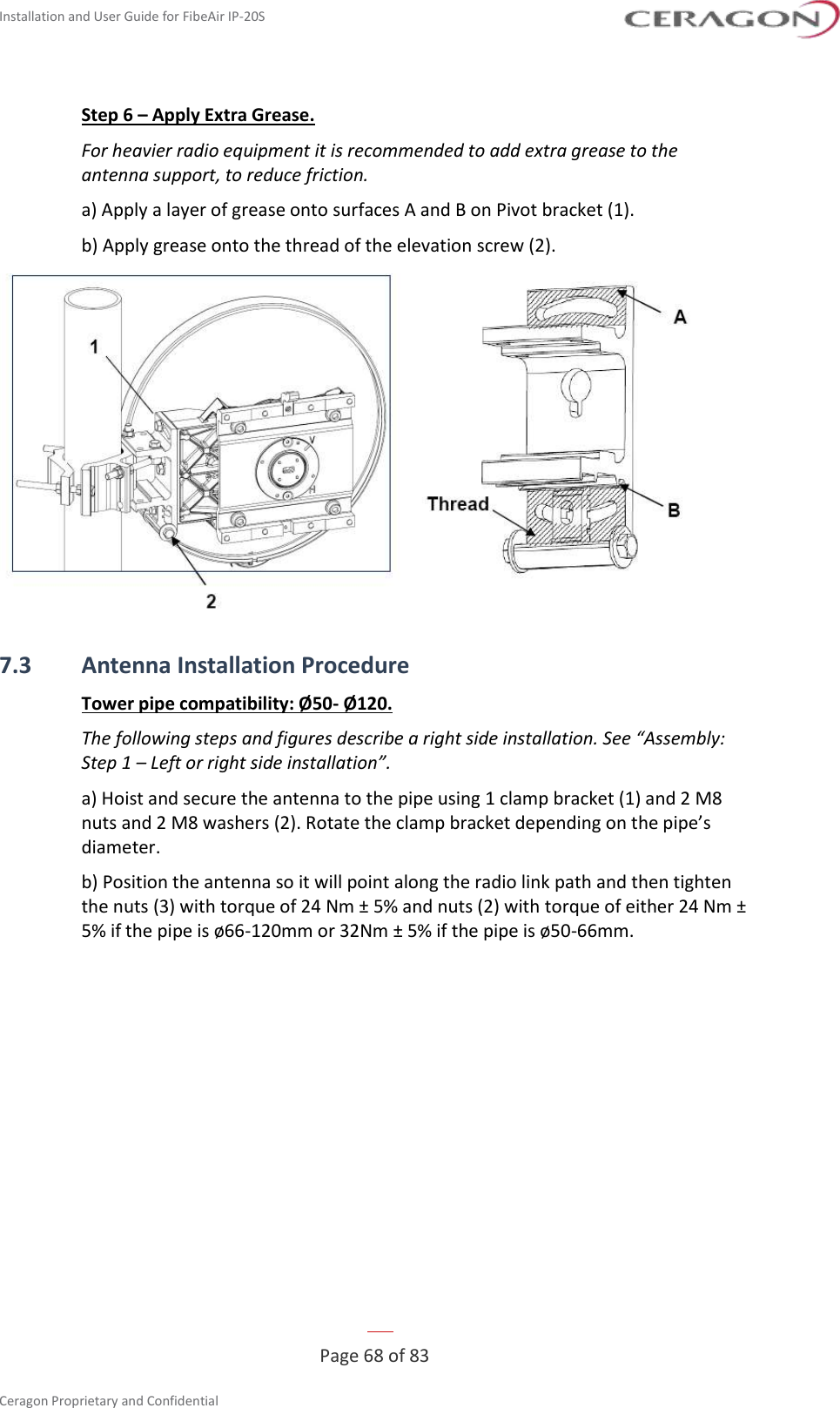
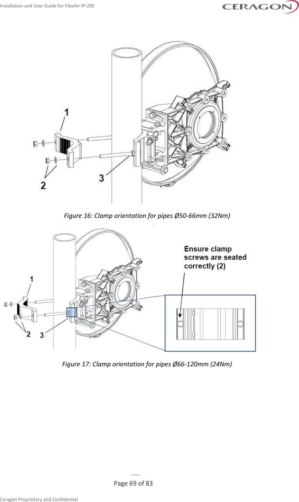
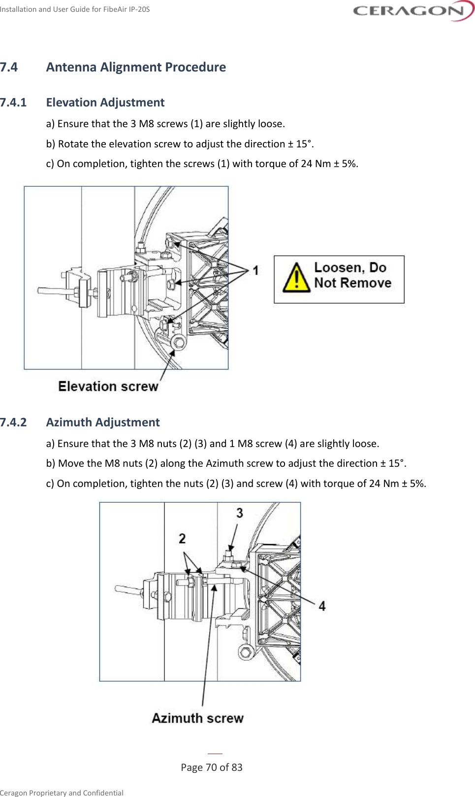
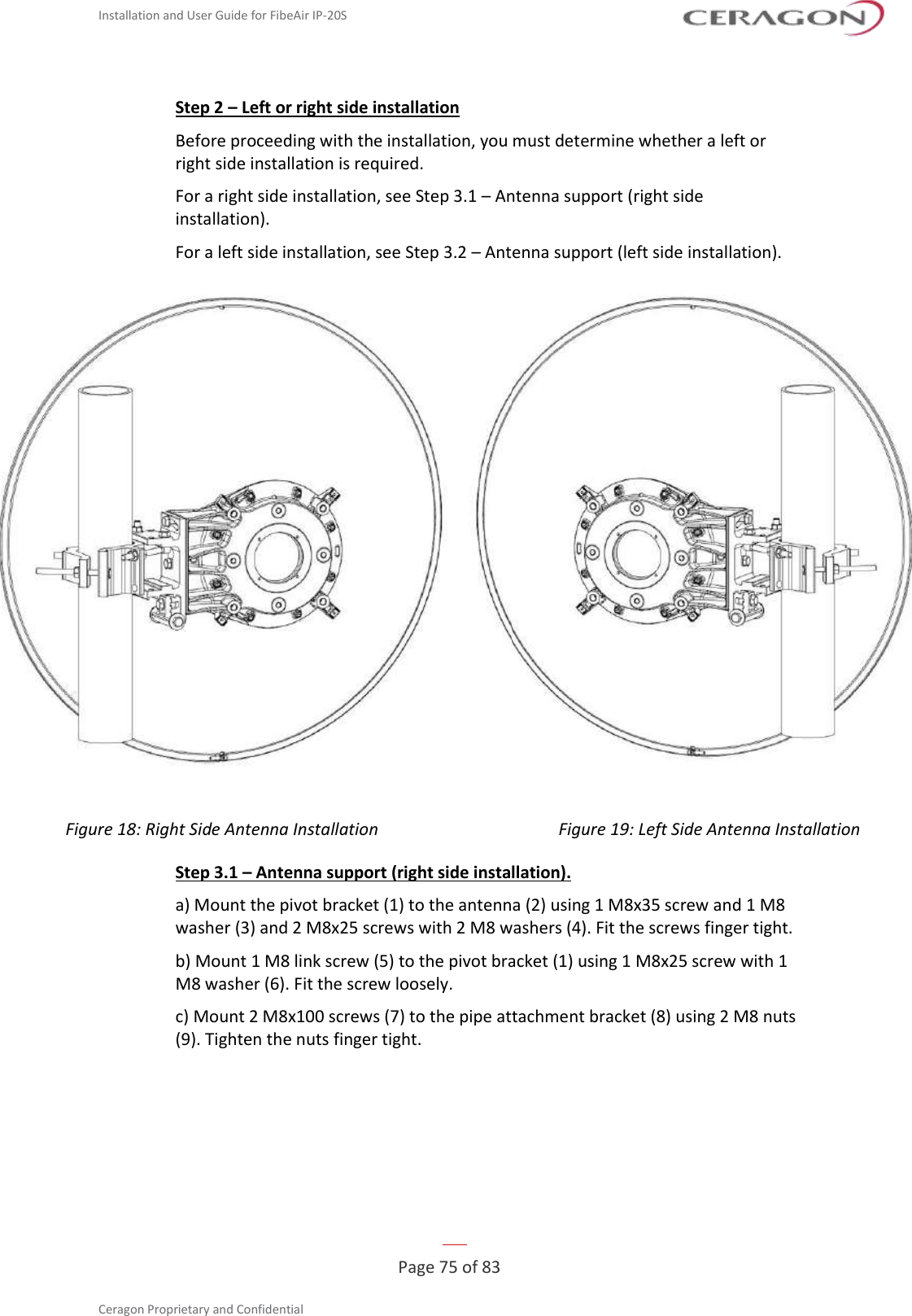
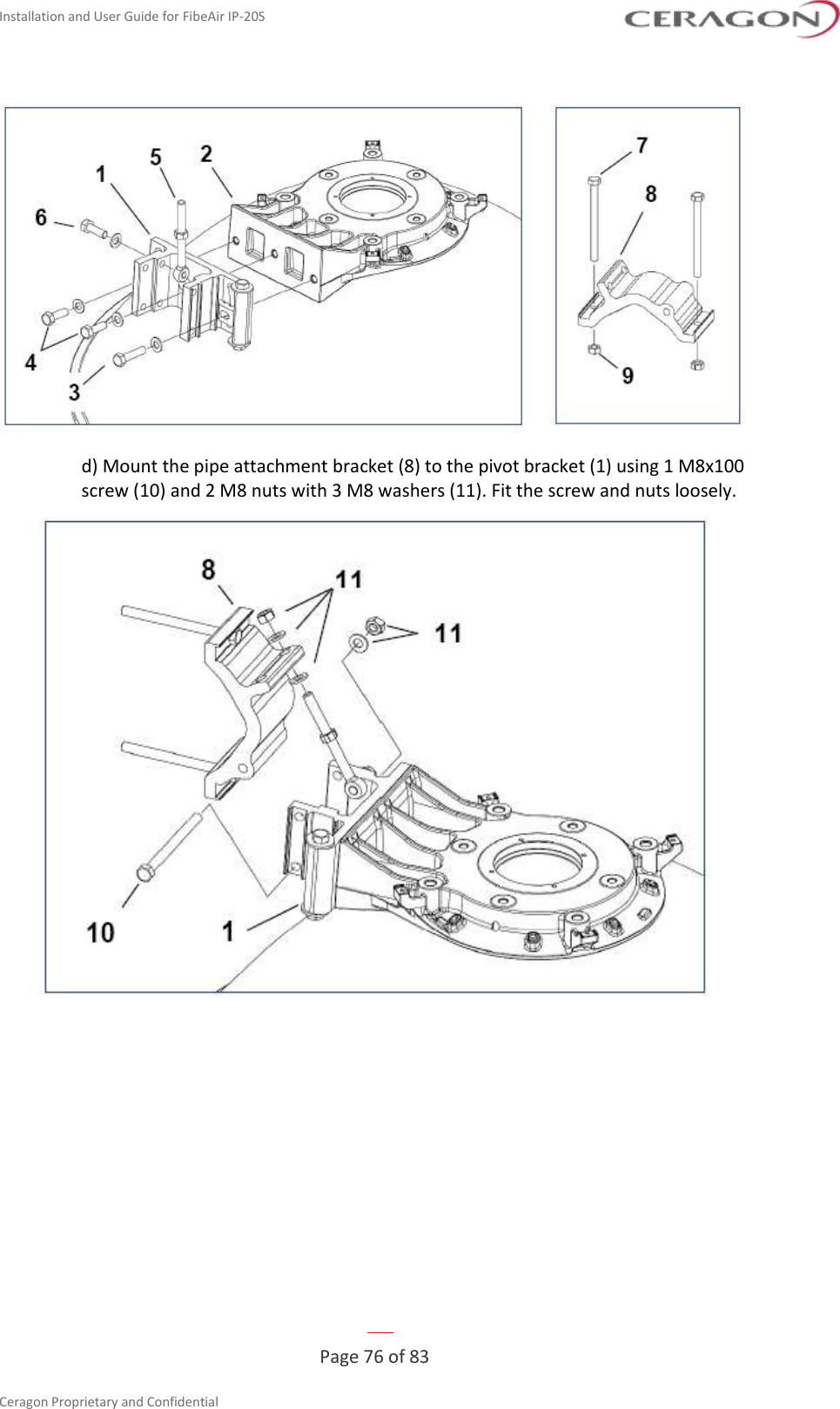
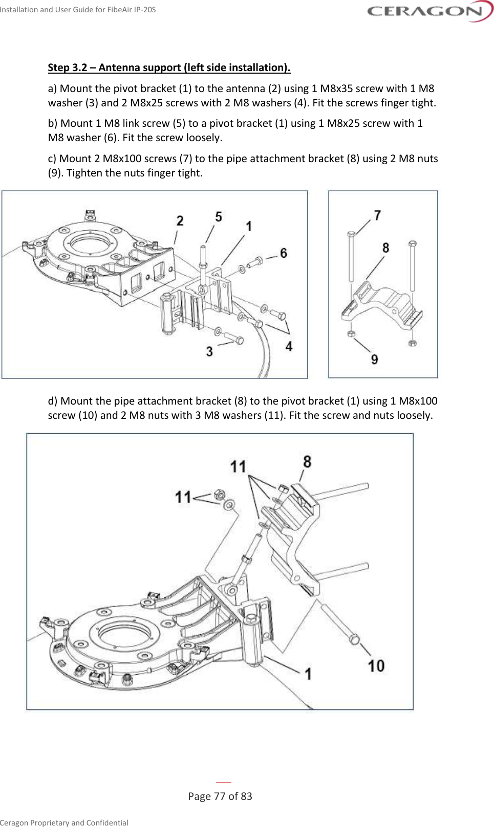
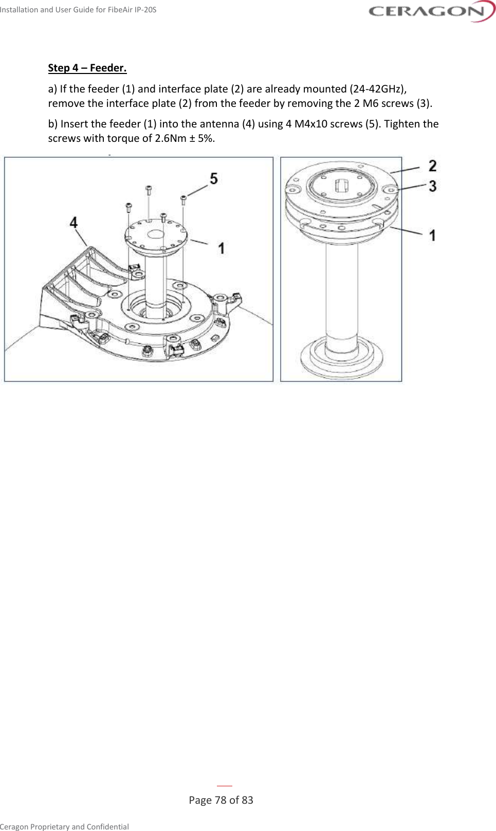
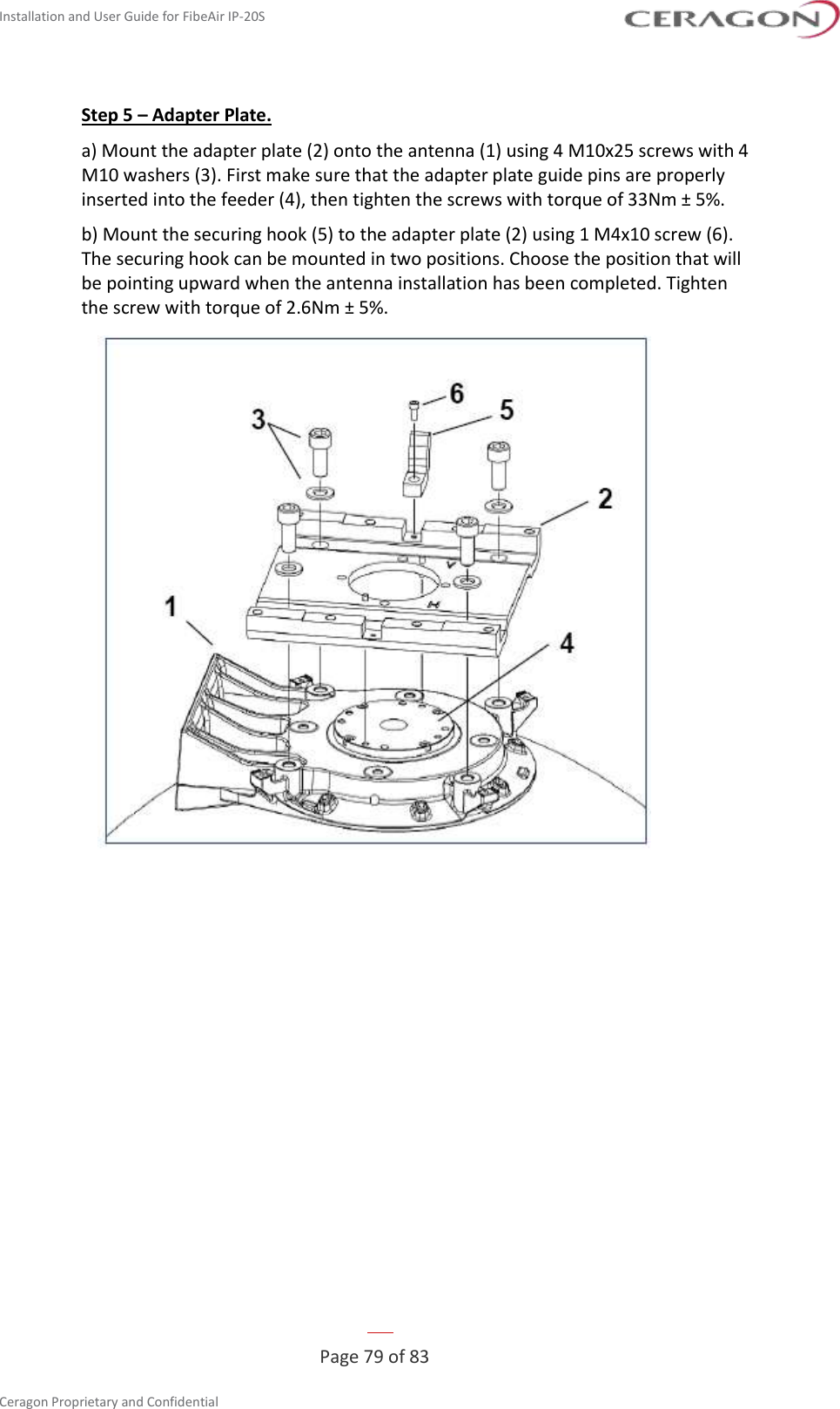
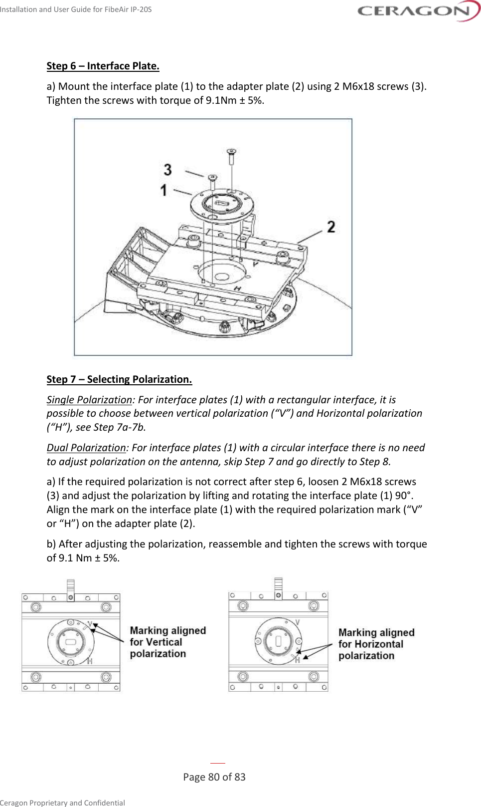
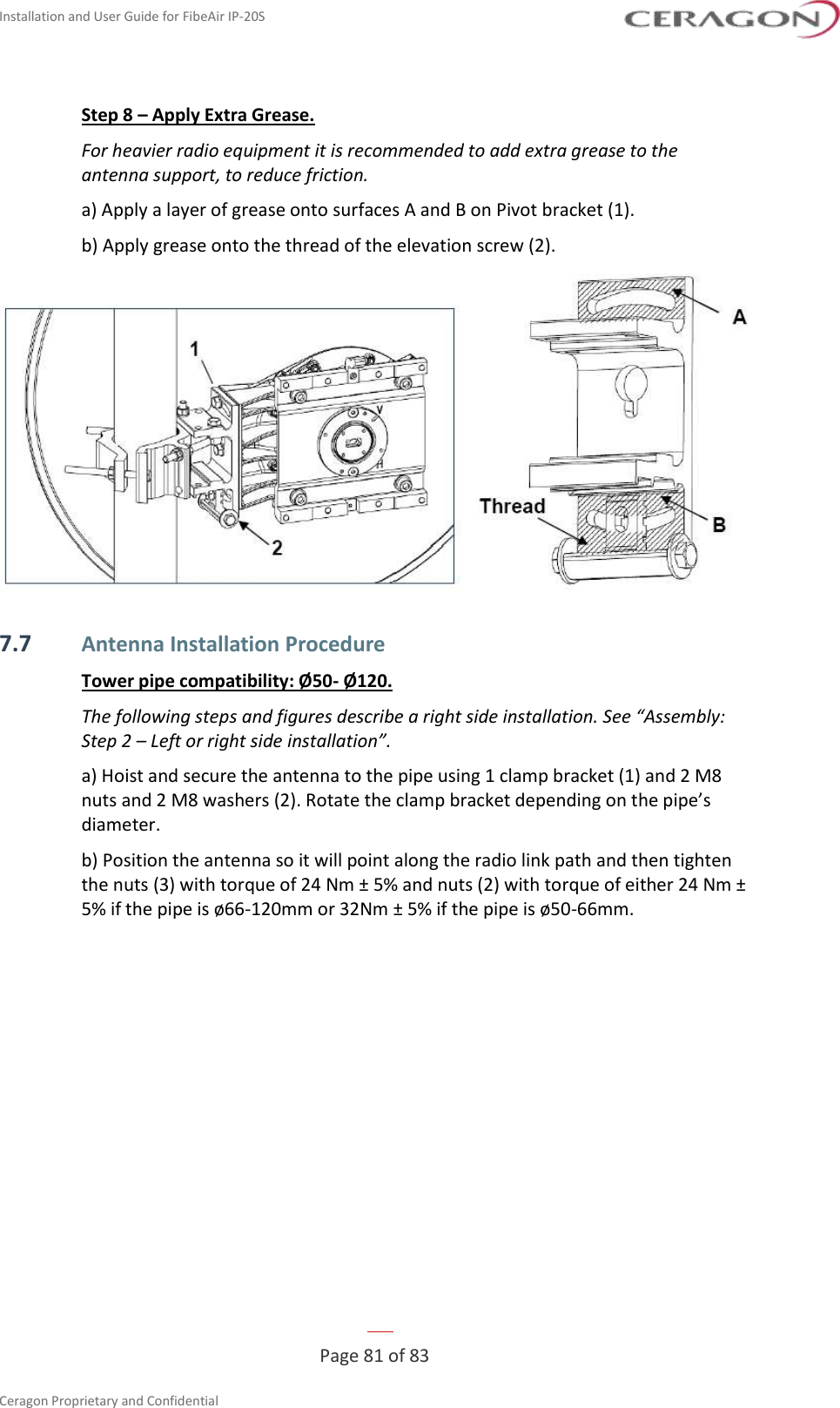
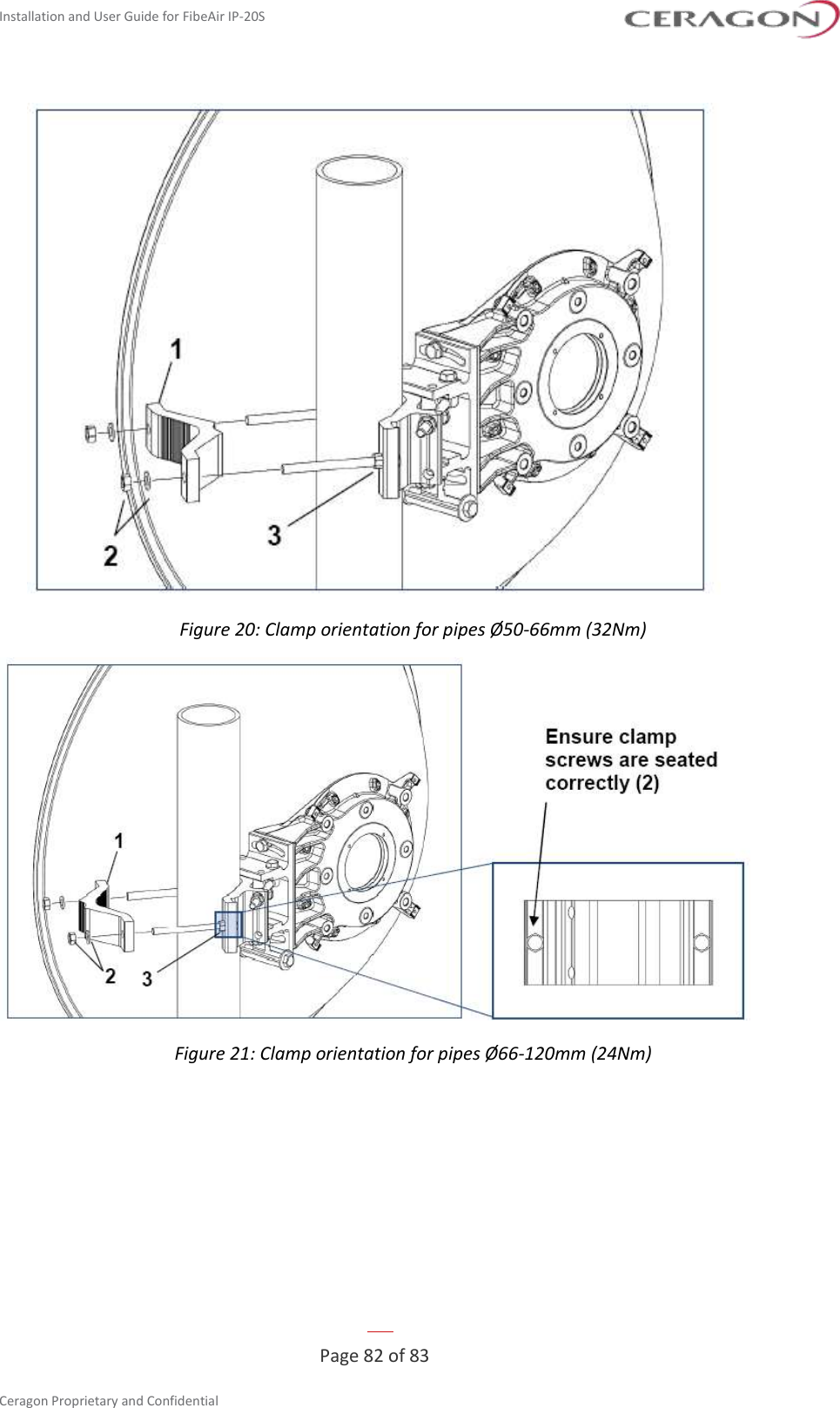
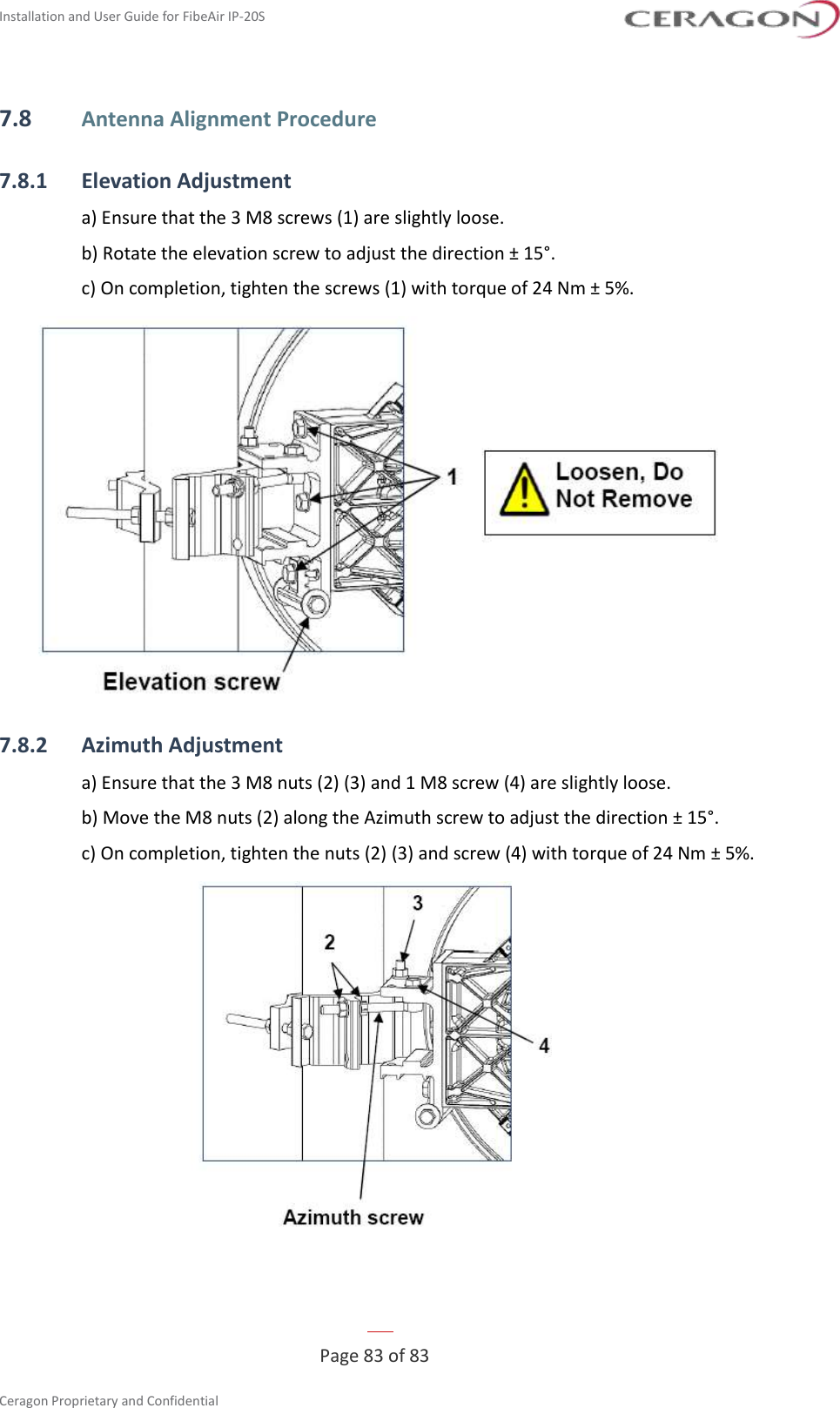
![Installation and User Guide for FibeAir IP-20S Page 26 of 83 Ceragon Proprietary and Confidential 3.5.4 Ethernet Cable and Specifications Marketing P/N Description CAT5E_SFUTP_Outdoor_50m CABLE,RJ45 TO RJ45 STR 50M,CAT-5E,ETHER,UV RES CAT5E_SFUTP_Outdoor_75m CABLE,RJ45 TO RJ45 STR 75M,CAT-5E,ETHER,UV RES CAT5E_SFUTP_Outdoor_305m_drum CABLE,MATERIAL,CAT-5E,SFUTP,4X2X24AWG,UV RESISTANCE,305M CAT5E_Arm_50m CABLE,RJ45 TO RJ45 STR,50M,CAT-5E,M28 GLAN,ARM,UV RESISTANCE CAT5E_Arm_70m CAT5E_Arm_75mCABLE,RJ45 TO RJ45 STR,70M,CAT-5E,M28 GLAN,ARM,UV RESISTANCE CAT5E_Arm_305m_drum CABLE,MATERIAL,CAT-5E,FTP,4X2X24AWG,ARMORED,UV RESIST,305M This cable has the following specifications: • Suitable for: ◦ Fast Ethernet ◦ Gigabit Ethernet ◦ PoE Cable Design – The numbers in the figure below refer to the items listed beneath the figure. • [1]Conductor • [2]Insulation • [3]Screen: Alu/Pet foil. Alu outside • [4]Tinned copper braid • [5]Jacket](https://usermanual.wiki/Ceragon-Networks/IP20S24/User-Guide-3763792-Page-26.png)