Chamberlain Group The 1D8169-1 MyQ- Garage Door Opener User Manual My
Chamberlain Group Inc, The MyQ- Garage Door Opener My
UserManual.wiki
>
Chamberlain Group The
>
1D8169-1 User Manual
>
User manual
Contents
1.
User manual
2.
User manual 1 of 2
3.
User manual 2 of 2
User manual
Navigation menu
Upload a User Manual
Namespaces
Wiki Guide
HTML
PDF
Info
Views
User Manual
Discussion / Help
Navigation
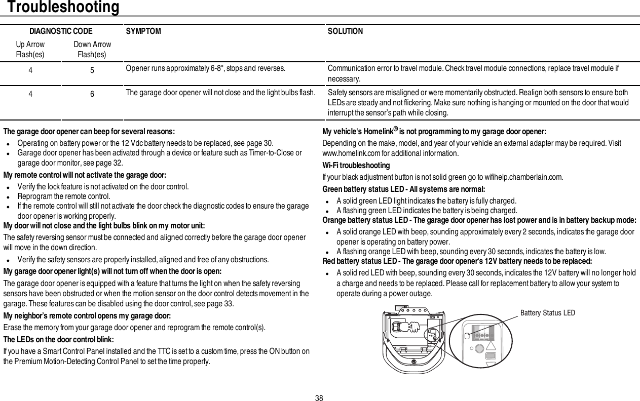
![29AdjustmentsSTEP 2 Test the Safety Reversal SystemWithout a properly installed safety reversal system, persons (particularly small children) could beSERIOUSLY INJURED or KILLED by a closing garage door.lSafety reversal system MUST be tested every month.lAfter ANY adjustmentsare made,the safety reversal system MUST be tested. Door MUST reverseon contact with 1-1/2" (3.8 cm) high object (or 2x4 laid flat) on the floor.1. With the door fully open, place a 1-1/2 inch (3.8 cm) board (or a 2x4 laid flat) on the floor,centered under the garage door.2. Operate the door in the down direction. The door MUST reverse on striking the obstruction.If the door stops and does not reverse on the obstruction,the down travel needsto be increased (refer toAdjustmentStep 1). Repeatthe test. When the door reverses on the 1-1/2" (3.8 cm) board (or 2x4 laidflat), remove the obstruction and run the opener through 3 or 4 complete travel cycles to test adjustment.If the garage door opener continues to fail the safety reversal test,call a trained door systemstechnician.1 2STEP 3 Test the Protector System®Without a properly installed safety reversing sensor, persons (particularly small children) could beSERIOUSLY INJURED or KILLED by a closing garage door.1. Open the door. Place the garage door opener carton in the path of the door.2. Press the remote control push button to close the door.The door will not move more than an inch(2.5 cm),and the garage door opener lights will flash 10 times.The garage door opener will not close from a remote control ifthe LED in either safetyreversing sensoris off (alerting you to the fact that the sensor ismisaligned or obstructed). Ifthe garage door openercloses the door when the safety reversing sensor is obstructed (and the sensors are no more than 6inches [15 cm] above the floor), call for a trained door systemstechnician.12](https://usermanual.wiki/Chamberlain-Group-The/1D8169-1.User-manual/User-Guide-2386132-Page-30.png)
![40Warranty CHAMBERLAIN® LIMITED WARRANTYThe Chamberlain Group, Inc.® (“Seller”) warrants to the fi rst retail purchaser of this product, for the residence in which this product is originally installed, that it is free from defects in materials and/or workmanship for a specifi c period of time as defi ned below (the “Warranty Period”). The warranty period commences from the date of purchase.WARRANTY PERIODParts Motor Accessories Belt Battery Backup5 Years Lifetime 1 year Lifetime 1 yearThe proper operation of this product is dependent on your compliance with the instructions regarding installation, operation, and maintenance and testing. Failure to comply strictly with those instructions will void this limited warranty in its entirety. If, during the limited warranty period, this product appears to contain a defect covered by this limited warranty, call 1-800- 528-9131, toll free, before dismantling this product. You will be advised of disassembly and shipping instructions when you call. Then send the product or component, pre-paid and insured, as directed to our service center for warranty repair. Please include a brief description of the problem and a dated proof- of-purchase receipt with any product returned for warranty repair. Products returned to Seller for warranty repair, which upon receipt by Seller are confi rmed to be defective and covered by this limited warranty, will be repaired or replaced (at Seller’s sole option) at no cost to you and returned pre-paid. Defective parts will be repaired or replaced with new or factory rebuilt parts at Seller’s sole option. [You are responsible for any costs incurred in removing and/or reinstalling the product or any component .]ALL IMPLIED WARRANTIES FOR THE PRODUCT, INCLUDING BUT NOT LIMITED TO ANY IMPLIED WARRANTIES OF MERCHANTABILITY AND FITNESS FOR A PARTICULAR PURPOSE, ARE LIMITED IN DURATION TO THE APPLICABLE LIMITED WARRANTY PERIOD SET FORTH ABOVE FOR THE RELATED COMPONENT(S), AND NO IMPLIED WARRANTIES WILL EXIST OR APPLY AFTER SUCH PERIOD. Some States and Provinces do not allow limitations on how long an implied warranty lasts, so the above limitation may not apply to you. THIS LIMITED WARRANTY DOES NOT COVER NON-DEFECT DAMAGE, DAMAGE CAUSED BY IMPROPER INSTALLATION, OPERATION OR CARE (INCLUDING, BUT NOT LIMITED TO ABUSE, MISUSE, FAILURE TO PROVIDE REASONABLE AND NECESSARY MAINTENANCE, UNAUTHORIZED REPAIRS OR ANY ALTERATIONS TO THIS PRODUCT), LABOR CHARGES FOR REINSTALLING A REPAIRED OR REPLACED UNIT, REPLACEMENT OF CONSUMABLE ITEMS (E.G., BATTERIES IN REMOTE CONTROL TRANSMITTERS AND LIGHT BULBS), OR UNITS INSTALLED FOR NON-RESIDENTIAL USE. THIS LIMITED WARRANTY DOES NOT COVER ANY PROBLEMS WITH, OR RELATING TO, THE GARAGE DOOR OR GARAGE DOOR HARDWARE, INCLUDING BUT NOT LIMITED TO THE DOOR SPRINGS, DOOR ROLLERS, DOOR ALIGNMENT OR HINGES. THIS LIMITED WARRANTY ALSO DOES NOT COVER ANY PROBLEMS CAUSED BY INTERFERENCE. UNDER NO CIRCUMSTANCES SHALL SELLER BE LIABLE FOR CONSEQUENTIAL, INCIDENTAL OR SPECIAL DAMAGES ARISING IN CONNECTION WITH USE, OR INABILITY TO USE, THIS PRODUCT. IN NO EVENT SHALL SELLER’S LIABILITY FOR BREACH OF WARRANTY, BREACH OF CONTRACT, NEGLIGENCE OR STRICT LIABILITY EXCEED THE COST OF THE PRODUCT COVERED HEREBY. NO PERSON IS AUTHORIZED TO ASSUME FOR US ANY OTHER LIABILITY IN CONNECTION WITH THE SALE OF THIS PRODUCT.Some states and provinces do not allow the exclusion or limitation of consequential, incidental or special damages, so the above limitation or exclusion may not apply to you. This limited warranty gives you specifi c legal rights, and you may also have other rights, which vary from state to state and province to province.Contact InformationFor installation and service information, please visit:www.chamberlain.com/parts-and-supportIf you are ordering a repair part please have the following information: part number, part name, and model number.Address repair parts orders to:The Chamberlain Group, Inc.6050 S. Country Club RoadTucson, AZ 85706Register your new garage door opener at www.prodregister.com/chamberlainSTOP!This garage door opener WILL NOT work until the safety reversing sensors are properly installed and aligned.](https://usermanual.wiki/Chamberlain-Group-The/1D8169-1.User-manual/User-Guide-2386132-Page-41.png)