Chamberlain Group The 1D8169-1 MyQ- Garage Door Opener User Manual My
Chamberlain Group Inc, The MyQ- Garage Door Opener My
Contents
- 1. User manual
- 2. User manual 1 of 2
- 3. User manual 2 of 2
User manual
■ Please read this manual and the enclosed safety materials carefully!
■ Fasten the manual near the garage door after installation.
■ The door WILL NOT CLOSE unless the Protector System® is connected and
properly aligned.
■ Periodic checks of the garage door opener are required to ensure safe operation.
■ The model number label is located on the left side panel of your garage door
opener.
■ This garage door opener is compatible with MyQ® and Security✚ 2.0™
accessories.
■ DO NOT install on a one-piece door if using devices or features providing
unattended close. Unattended devices and features are to be used ONLY with
sectional doors.
CONTENTS
Preparation. . . . . . . . . . . . . . . .1-4
Assembly . . . . . . . . . . . . . . . . .5-8
Installation . . . . . . . . . . . . . . .9-26
Adjustments . . . . . . . . . . . . . 27-29
Battery Backup. . . . . . . . . . . . . . 30
Operation . . . . . . . . . . . . . . . 31-35
Using your Garage
Door Opener. . . . . . . . . . . . . . . . 32
To Open the Door Manually . . . . 32
Door Control. . . . . . . . . . . . . .33-34
MyQ® Smartphone Control. . . . . 34
Remote Control and
Keyless Entry . . . . . . . . . . . . . . . 35
To Erase the Memory . . . . . . . . . 35
Maintenance . . . . . . . . . . . . . . . 36
Troubleshooting. . . . . . . . . . . 37-38
Accessories. . . . . . . . . . . . . . . . 39
Warranty. . . . . . . . . . . . . . . . . . 40
Repair Parts . . . . . . . . . . . . . 41-42
1-1/4 hps* Belt Drive
Garage Door Opener with
MyQ® Smartphone Control
and Battery Backup
The Chamberlain Group, Inc.
845 Larch Avenue
Elmhurst, Illinois 60126-1196
www.chamberlain.com
www.mychamberlain.com
Models
• LW9000WF
• HD950WF
• WD1000WF
FOR RESIDENTIAL USE ONLY
MyQ® Serial Number:
Affi x MyQ® Serial
Number Label Here
* Horsepower similar (hps) designates that this garage
door opener system meets Chamberlain’s pulling force
specification for a 1-1/4 horsepower garage door opener.
1
Safety Symbol and Signal Word Review
This garage door opener has been designed and tested to offer safe service provided it isinstalled,
operated,maintained and tested in strictaccordance with the instructionsand warnings contained in this
manual.
When you see these Safety Symbols and Signal Words on the following pages,they will alert you to the
possibility of serious injury or death ifyou do not comply with the warnings that accompany them.The
hazard may come from something mechanical or from electric shock. Read the warningscarefully.
Mechanical
Electrical
When you see this Signal Word on the following pages,itwill alert you to the possibility ofdamage to
your garage door and/or the garage door opener if you do notcomply with the cautionarystatementsthat
accompany it. Read them carefully.
Unattended Operation
The Timer-to-Close (TTC) feature,the MyQ®Smartphone Control app, and MyQ®Garage Door and
Gate Monitor are examples ofunattended close and are to be used ONLY with sectional doors. Any
device or feature thatallows the door to close without being in the line of sight ofthe door is considered
unattended close.The Timer-to-Close (TTC) feature, the MyQ®Smartphone Control,and anyother
MyQ®devices are to be used ONLY with sectional doors.
Check the Door
To prevent possible SERIOUS INJURY or DEATH:
lALWAYS call a trained door systems technician if garage door binds, sticks, or is out of balance.
An unbalanced garage door may NOT reverse when required.
lNEVER try to loosen, move or adjust garage door, door springs, cables, pulleys, brackets or their
hardware, ALL of which are under EXTREME tension.
lDisable ALL locks and remove ALL ropes connected to garage door BEFORE installation and
operating garage door opener to avoid entanglement.
lDO NOT install on a one-piece door if using devicesor features providing unattended close.
Unattended devices and features are to be used ONLY with sectional doors.
To prevent damage to garage door and opener:
lALWAYS disable locks BEFORE installing and operating the opener.
lONLY operate garage door opener at120 V, 60 Hz to avoid malfunction and damage.
Before you begin:
1. Disable locksand remove anyropes connected to the garage door.
2. Lift the door halfway up. Release the door. If balanced, it should stay
in place, supported entirely by its springs.
3. Raise and lower the door to check for binding or sticking. Ifyour door
binds, sticks, or is out of balance, call a trained door systems
technician.
4. Check the seal on the bottom ofthe door. Any gap between the floor
and the bottom ofthe door mustnot exceed 1/4 inch (6 mm).
Otherwise, the safety reversal system may not work properly.
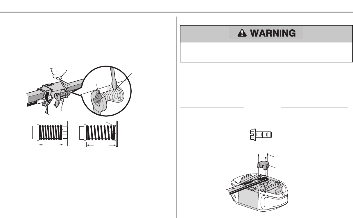
5. The opener should be installed above the center ofthe door. Ifthere
is a torsion spring or center bearing plate in the way ofthe header
bracket, it maybe installed within 4feet(1.2 m) to the leftor rightof
the door center. See page10.
Torsion
Spring
Extension
Spring
OR
Preparation
2
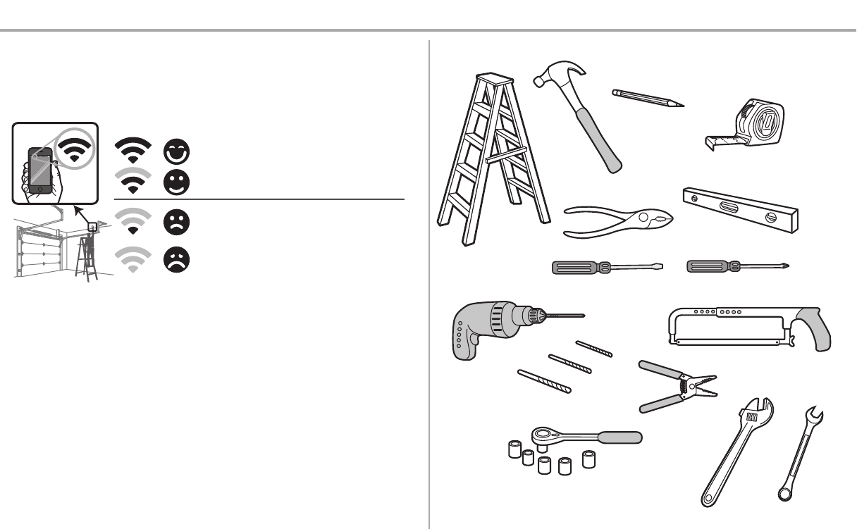
Test the Wi-Fi®Signal Strength in your garage
You will need a router with Wi-Fi®,a broadband internet connection and a smartphone or other mobile
device.Make sure your mobile device isconnected to your home network.Hold your mobile device in the
place where your garage door opener will be installed and check the Wi-Fi signal strength.Go to
wifihelp.chamberlain.com for more details.
You’re all set!
Install your new garage door opener.
Wi-Fi signal is weak or no signal. You may want to:
• Move the router closer to the garage door opener to
minimize interference from walls and other objects
• Buy a Wi-Fi extender
• Buy a Chamberlain Internet Gateway (CIGBU),
see page 39
• Go to wifihelp.chamberlain.com for more details
Signal Strength:
=
=
=
=
Additional Items You May Need:
Survey your garage area to see if you will need any of the following items:
l(2) 2X4 Pieces of wood : May be used to fasten the header bracket to the structural supports.
Also used to position the garage door opener during installation and for testing the safety
reversing sensors.
lSupport bracket and fastening hardware: Mustbe used if you have a finished ceiling in your
garage.
lExtension brackets (MODEL 041A5281-1) or wood blocks: Depending upon garage
construction, extension brackets or wood blocks may be needed to install the safety reversing
sensor.
lFastening hardware: Alternate floor mounting of the safety reversing sensor will require
hardware notprovided.
lOutside quick release (MODEL 7702CB): Required for a garage with NO access door.
lDoor reinforcement: Required if you have a lightweight steel, aluminum, fiberglass or glass
panel door.
lRail extension kit: Required if your garage door is more than 7 feet(2.13 m) high.
Tools Needed
3/16
7/16
1/2
5/32
5/16
5/8
9/16
1/4
7/16
Preparation
3
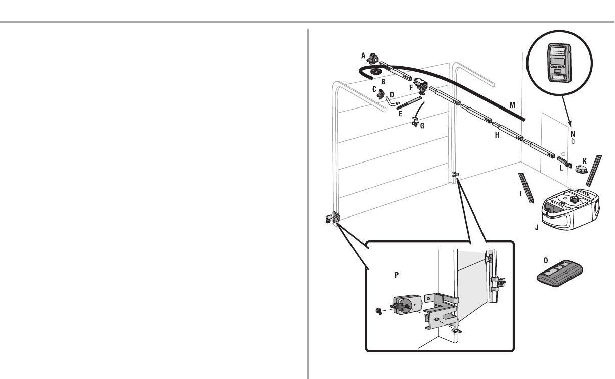
Carton Inventory
Your garage door opener is packaged in one carton which contains the motor unit and all parts
illustrated below.Accessoriesvarydepending on the garage door opener model purchased.Depending
on your model, other accessories may be included with your garage door opener. Instructions for these
accessories will be attached to the accessory and are not included in this manual.Save the carton and
packing material until the installation and adjustment is complete. The images throughout this manual
are for reference only and your product may look different.
A. Header bracket
B. Pulley
C. Door bracket
D. Curved door arm
E. Straight door arm
(Packaged inside front rail section)
F. Trolley
NOTE: Be sure to assemble the trolley before sliding onto rail.
G. Emergency release rope and handle
H. Rail (1 frontand 4 center sections)
I. Hanging brackets (2)
(Packaged inside the front rail section)
J. Garage door opener (motor unit)
K. Sprocket cover and screws
L. “U” bracket
M. Belt
N. Door control (Smart Control Panel®)
O. Remote control (2)
P. The Protector System®
Safety reversing sensors with 2 conductor white and white/black wire attached: Sending Sensor
(1), Receiving Sensor (1), and Safety Sensor Brackets (2)
NOT SHOWN
White and red/white wire
Owner's manual
Hardware
Preparation
4
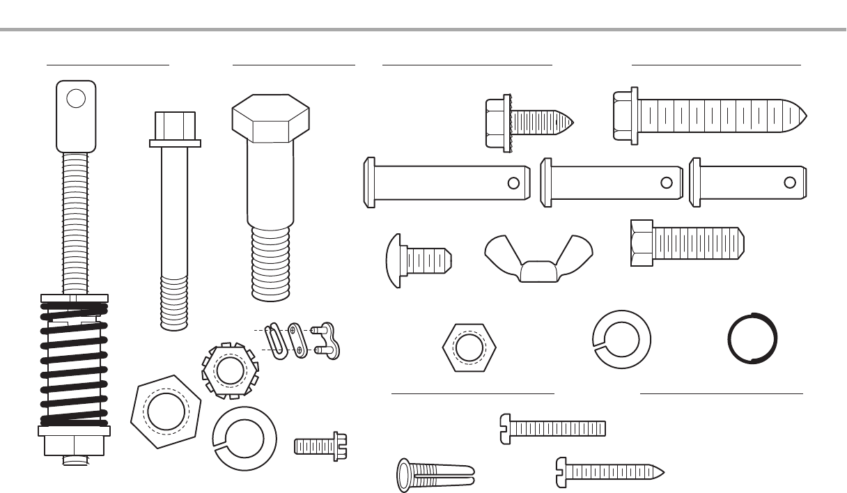
Hardware
Clevis Pin 5/16"x1-1/2"
Ring Fastener (3)
Hex Bolt 5/16"-18x7/8" (4)
Lock Washer
5/16"-18 (5)
Nut
5/16"-18 (6)
Self-Threading Screw
1/4"-14x5/8" (2)
Clevis Pin 5/16"x1"
Clevis Pin 5/16"x1-1/4"
Carriage Bolt
1/4"-20x1/2" (2)
Wing Nut 1/4"-20 (2)
ASSEMBLY INSTALLATION
Screw 6ABx1" (2)
Drywall Anchors (2)
Screw 6-32x1" (2)
DOOR CONTROL
Insulated
Staples
(Not Shown)
Lag Screw 5/16"-9x1-5/8" (4)
Hex Screw
#8x3/8" (3)
(packed with the
sprocket cover)
Bolt
1/4"-20x1-3/4"
Lock Nut
1/4"-20
Bolt
Nut 3/8"
Lock Washer 3/8"
Master Link
Spring
Trolley Nut
Threaded
Shaft
with
Preparation
5
Assembly
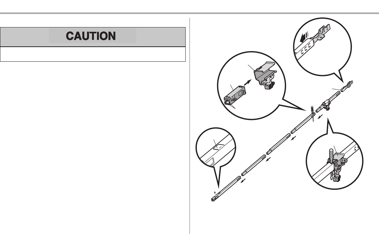
STEP 1 Assemble the rail and install the trolley
To prevent INJURY from pinching, keep hands and fingers away from the joints while assembling the
rail.
To avoid installation difficulties, do not run the garage door opener until instructed to do so.
The front rail has a cut out “window” at the door end. The rail tab MUST be on top of the rail when
assembled.
1. Remove the straight door arm and hanging bracket packaged inside the front rail and set aside
for Installation Step 5 and 9.NOTE: To prevent INJURY while unpacking the rail carefully remove
the straight door arm stored within the rail section.
2. Align the rail sections on a flat surface as shown and slide the tapered ends into the larger ones.
Tabs along the side will lockinto place.
3. Place the motor uniton packing material to protectthe cover,and rest the back end of the rail on
top.For convenience,put a support under the frontend ofthe rail.
4. As a temporary stop, inserta screwdriver into the hole in the second rail section fromthe motor
unit, as shown.
5. Check to be sure there are 4 plasticwear padsinside the inner trolley.If they became loose
during shipping, check all packing material. Snap them back into position as shown.
6. Slide the trolley assemblytoward the screwdriver as shown.
7. Slide the rail onto the “U” bracket,until itreaches all the stops on the top and sides of the “U”
bracket.
To garage
door opener
(TO MOTOR UNIT)
Front Rail
Section
(TO DOOR)
“U” Bracket
Outer Trolley
Inner Trolley
Wear Pads
SLIDE TO STOPS
ON TOP AND
SIDES OF
“U” BRACKET
Trolley
Rail Tab
6
Assembly
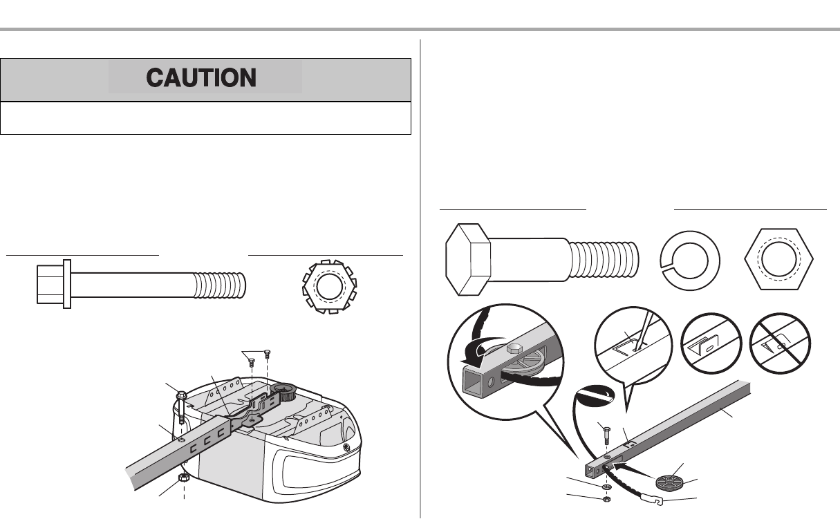
STEP 2 Fasten the rail to the motor unit
To avoid SERIOUS damage to garage door opener,use ONLY those bolts/fastenersmounted in the
top ofthe opener.
1. Insert a 1/4"-20x1-3/4" boltinto the cover protection bolt hole on the back end of the rail as
shown.Tighten securely with a 1/4"-20 lock nut. DO NOT overtighten.
2. Remove the bolts from the top ofthe motor unit.
3. Use the carton to supportthe front end of the rail.
4. Place the “U” bracket, flat side down onto the motor unitand align the bracket holes with the bolt
holes.
5. Fasten the “U” bracket with the previously removed bolts;DO NOT use anypower tools.The use
ofpower tools maypermanently damage the garage door opener.
“U” Bracket
Cover Protection Bolt Hole
Bolt 1/4"-20x1-3/4"
Lock Nut 1/4"-20
Bolts (Mounted in the garage door opener)
HARDWARE
Bolt 1/4"-20x1-3/4"
Lock Nut 1/4"-20
STEP 3 Install the idler pulley
1. Lay the beltbeside the rail, as shown.Grasp the end with the hooked trolley connector and pass
approximately 12" (30 cm) of beltthrough the window. Keep the ribbed side toward the rail, and
allow it to hang until AssemblyStep 4.
2. Remove the tape from the idler pulley.The inside center should be pre-greased. Ifdry,regrease
to ensure proper operation.
3. Place the idler pulley into the window as shown.
4. Insert the idler bolt from the top through the rail and pulley. Tighten with a 3/8" lockwasher and
nut underneath the rail until the lock washer is compressed.
5. Rotate the pulley to be sure it spins freely.
6. Locate the rail tab. The rail tab isnear the idler pulley on the front rail section.Use a flathead
screwdriver and liftthe rail tab until the tab is vertical (90º).
Rail
Trolley Connector
Bolt
Lock Washer 3/8"
Nut 3/8"
Rail Tab
CORRECT INCORRECT
Idler Pulley
Grease Inside Pulley
HARDWARE
Bolt Nut 3/8"
Lock Washer 3/8"
Rail Tab
7
Assembly
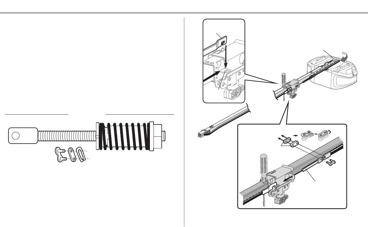
STEP 4 Install the belt
1. Pull the beltaround the idler pulley and toward the trolley.The ribbed side must contact the
pulley.
2. Hook the trolley connector into the retaining slot on the trolley asshown (Figure 1).
3. With the trolley againstthe screwdriver,dispense the remainder ofthe belt along the rail
lengthtoward the motor unit and around the sprocket (Figure 2). The sprocket teeth must engage
the belt.
4. Check to make sure the belt is not twisted. Connectthe trolleythreaded shaft with the master link
(Figure 3).
lPush pins of master link bar through holes in end of belt and trolley threaded shaft.
lPush master link cap over pins and pastpin notches.
lSlide the closed end of the clip-on spring over one of the pins.Push the open end of the
clip-on spring onto the other pin.
5. Remove the spring trolley nutfrom the threaded shaft.
6. Insert the trolley threaded shaft through the hole in the trolley.
HARDWARE
Master
Link
Threaded Shaft with Spring Trolley Nut
Sprocket
Figure 3
Threaded Shaft
Master Link
Figure 2
Trolley Connector
Figure 1
Retaining
Slot
8
Assembly
STEP 5 Tighten the belt
1. By hand, thread the spring trolley nut on the threaded shaft until it is finger tight against the
trolley.Do notuse any tools.Remove the screwdriver.
2. Insert a flathead screwdriver tip into one ofthe nut ring slots and brace it firmlyagainstthe trolley.
3. Tighten the spring trolley nut with an adjustable wrench or a 7/16" open end wrench about a
quarter turn until the spring releases and snaps the nut ring againstthe trolley.Thissets the
spring to optimum belt tension.
Nut Ring
BEFORE
1"
(2.5
cm)
Nut Ring
AFTER
1-1/4"
(3.18 cm)
Spring
Trolley Nut
Nut Ring Slot
STEP 6 Install the sprocket cover
To avoid possible SERIOUS INJURY to finger from moving garage door opener:
lALWAYS keep hand clear ofsprocket while operating opener.
lSecurely attach sprocket cover BEFORE operating.
1. Position the sprocket cover over the sprocket asshown and fasten to the mounting plate with
8x3/8" hex screws provided.
You have now finished assembling your garage door opener. Please read the following warnings
before proceeding to the installation section.
Hex Screw #8x3/8"
(Packed with the
sprocket cover)
HARDWARE
Hex Screw #8x3/8"
Sprocket Cover
9
Installation
IMPORTANT INSTALLATION INSTRUCTIONS
To reduce the risk of SEVERE INJURY or DEATH:
1. READ AND FOLLOW ALL INSTALLATION WARNINGS AND INSTRUCTIONS.
2. Install garage door opener ONLY on properly balanced and lubricated garage door.An
improperly balanced door mayNOTreverse when required and could resultin SEVERE
INJURY or DEATH.
3. ALL repairsto cables, spring assemblies and other hardware MUST be made by a trained door
systems technician BEFORE installing opener.
4. Disable ALL locks and remove ALL ropes connected to garage door BEFORE installing opener
to avoid entanglement.
5. Install garage door opener 7 feet (2.13 m) or more above floor.
6. Mount the emergency release within reach,but atleast6 feet (1.83 m) above the floor and
avoiding contact with vehicles to avoid accidental release.
7. NEVER connectgarage door opener to power source until instructed to do so.
8. NEVER wear watches, rings or loose clothing while installing or servicing opener.They could be
caught in garage door or opener mechanisms.
9. Install wall-mounted garage door control:
lwithin sight ofthe garage door.
lout of reach of children at minimum height of 5 feet (1.5m).
laway from ALL moving parts of the door.
10. Place entrapment warning label on wall next to garage door control.
11. Place manual release/safety reverse test label in plain view on inside of garage door.
12. Upon completion of installation, test safety reversal system. Door MUST reverse on contact with a
1-1/2" (3.8 cm) high object(or a 2x4 laid flat) on the floor.
13. To avoid SERIOUS PERSONAL INJURY or DEATHfromelectrocution, disconnect ALL electric
and battery power BEFORE performing ANY service or maintenance.
14. DO NOTinstall on a one-piece door if using devices or features providing unattended close.
Unattended devices and features are to be used ONLY with sectional doors.
10
Installation
STEP 1 Determine the header bracket location
To prevent possible SERIOUS INJURY or DEATH:
lHeader bracket MUSTbe RIGIDLY fastened to structural support on header wall or ceiling,
otherwise garage door might NOT reverse when required. DO NOT install header bracket over
drywall.
lConcrete anchors MUST be used ifmounting header bracketor 2x4 into masonry.
lNEVER try to loosen, move or adjust garage door, springs, cables, pulleys, brackets, or their
hardware, ALL of which are under EXTREME tension.
lALWAYS call a trained door systems technician if garage door binds, sticks, or is out of balance.
An unbalanced garage door mightNOT reverse when required.
Installation procedures vary according to garage door types. Follow the instructions which apply to your
door.
1. Close the door and markthe inside vertical centerline of the garage door.
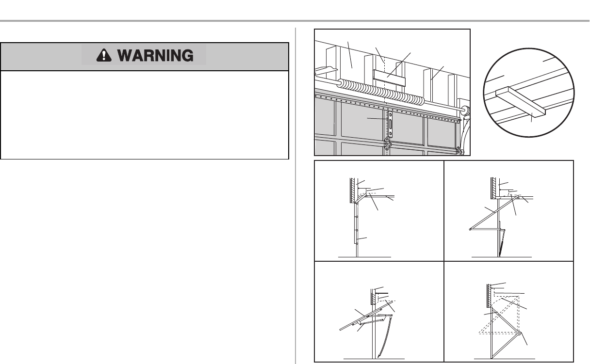
2. Extend the line onto the header wall above the door.You can fasten the header bracketwithin 4
feet(1.22 m) ofthe leftor rightof the door center only if a torsion spring or center bearing plate is
in the way;or you can attach it to the ceiling (see page 11) when clearance is minimal.(It may be
mounted on the wall upside down ifnecessary,to gain approximately1/2" (1 cm). Ifyou need to
install the header bracketon a 2x4 (on wall or ceiling),use lag screws(not provided) to securely
fasten the 2x4 to structural supportsas shown here and on page 11.
3. Open your door to the highestpointof travel as shown.Draw an intersecting horizontal line on
the header wall 2" (5 cm) above the high point:
l2" (5 cm) above the high point for sectional door and one-piece door with track.
l8" (20 cm) above the high point for one-piece door without track.
This height will provide travel clearance for the top edge ofthe door. NOTE: If the total number of inches
exceeds the height available in your garage, use the maximum height possible, or refer to page 11 for
ceiling installation.
Header Wall Vertical Centerline of Garage Door
2x4 Structural
Supports
Level
(Optional)
Unfinished
Ceiling
2x4
OPTIONAL CEILING MOUNT
FOR HEADER BRACKET
Sectional door with curved track
Header Wall
Track
2" (5 cm)
Highest
Point of
Travel
Door
One-piece door with horizontal track
Header Wall
Track
2" (5 cm)
Highest
Point of
Travel
Door
One-piece door without track:
jamb hardware
Header Wall
8" (20 cm)
Highest
Point of
Travel
Door
Jamb
Hardware
One-piece door without track:
pivot hardware
Header Wall
8" (20 cm)
Highest
Point of
Travel
Door
Pivot
11
Installation
STEP 2 Install the header bracket
You can attach the header bracket either to the wall above the garage door,or to the ceiling.Follow the
instructionswhich will work best for your particular requirements. Do not install the header bracket over
drywall. If installing into masonry, use concrete anchors (not provided).
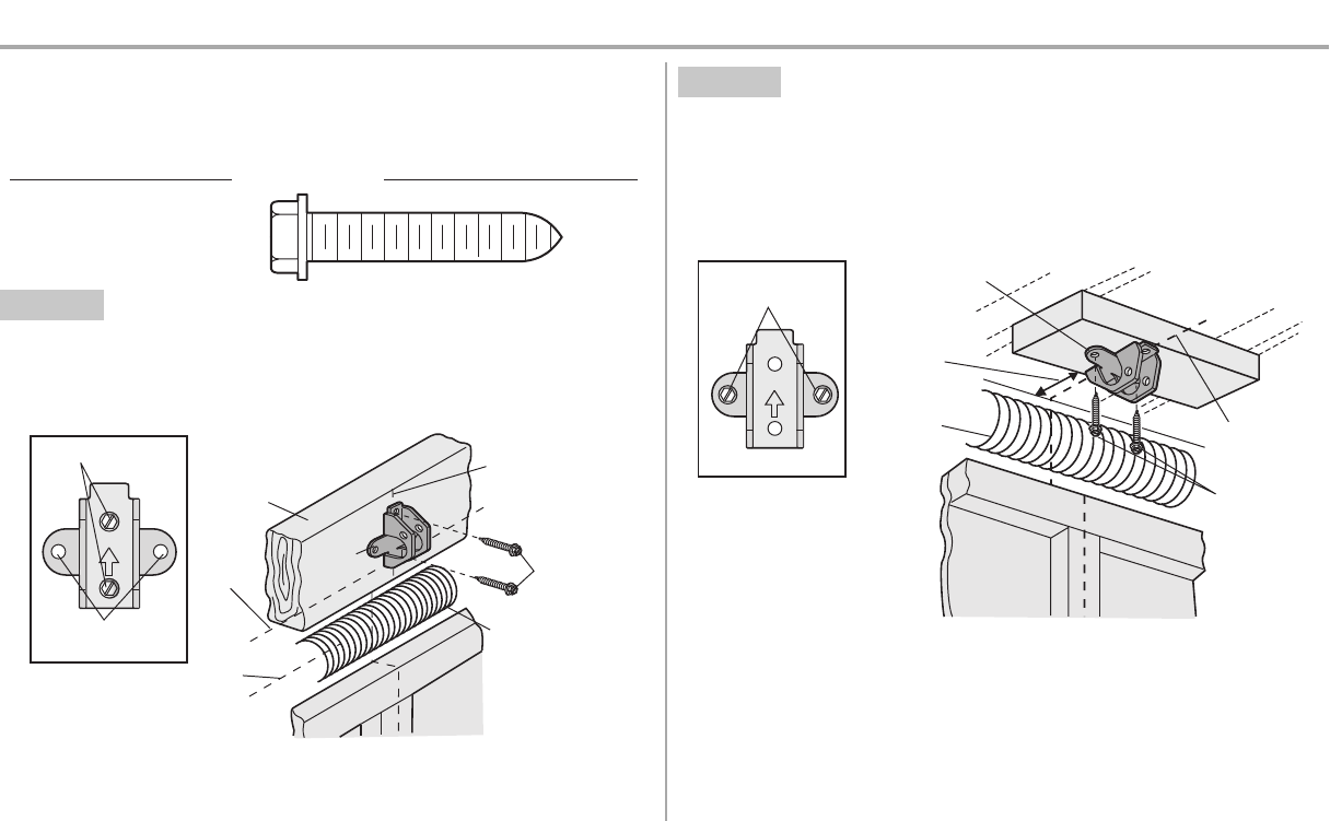
HARDWARE
Lag Screw 5/16"-9x1-5/8"
OPTION A WALL INSTALLATION
1. Center the bracketon the vertical centerline with the bottom edge of the bracket on the horizontal
line asshown (with the arrow pointing toward the ceiling).
2. Mark the vertical set ofbracketholes. Drill 3/16" pilot holesand fasten the bracket securely to a
structural supportwith the hardware provided.
UP
Wall Mount
Optional Mounting
Holes
Vertical
Centerline of
Garage Door
(Header Wall)
Header
Bracket
2x4 Structural
Support
Door Spring
(Garage Door)
Highest Point
of Garage
Door Travel
Horizontal
Line
Lag Screw
5/16"-9x1-5/8"
OPTION B CEILING INSTALLATION
1. Extend the vertical centerline onto the ceiling as shown.
2. Center the bracketon the vertical mark,no more than 6" (15cm) from the wall. Make sure the
arrow is pointing awayfrom the wall.The bracket can be mounted flush againstthe ceiling when
clearance is minimal.
3. Mark the side holes.Drill 3/16" pilot holes and fasten bracket securely to a structural supportwith
the hardware provided.
UP
(Header Wall)
Ceiling Mounting
Holes (Finished Ceiling)
Vertical
Centerline of
Garage Door
Header
Bracket
6" (15 cm)
Maximum
Door Spring
(Garage Door)
Lag Screw
5/16"-9x1-5/8"
12
Installation
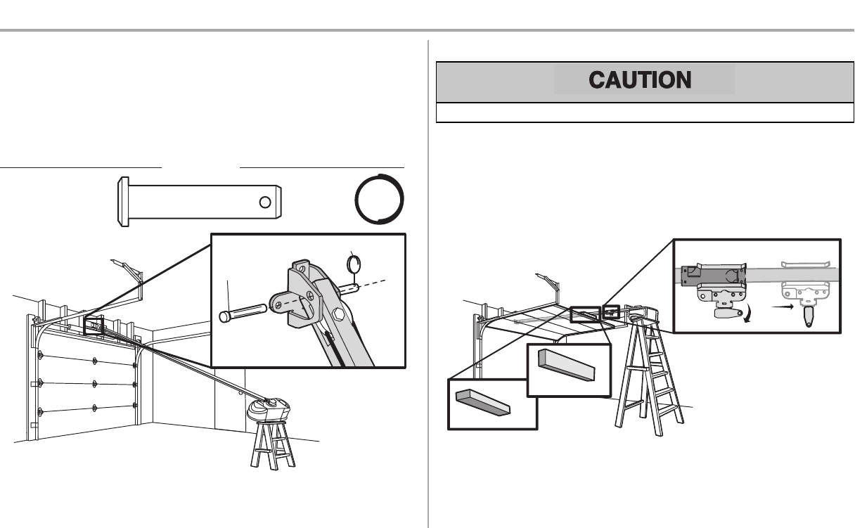
STEP 3 Attach the rail to the header bracket
1. Position the opener on the garage floor below the header bracket. Use packing material as a
protective base.
NOTE: If the door spring is in the way, you will need help. Have someone hold the opener
securely on a temporary support to allow the rail to clear the spring.
2. Position the rail bracket against the header bracket.
3. Align the bracket holes and join with a clevis pin as shown.
4. Insert a ring fastener to secure.
HARDWARE
Clevis Pin 5/16"x1-1/2" Ring Fastener
Clevis Pin
5/16"x1-1/2"
Ring Fastener
STEP 4 Position the garage door opener
To prevent damage to garage door,restgarage door opener rail on 2x4 placed on top section of door.
1. Remove the packing material and lift the garage door opener onto a ladder.
2. Fully open the door and place a 2x4 (laid flat) under the rail. For one-piece doors without tracks,
lay the 2x4 on it's side.
NOTE: A 2x4 is ideal for setting the distance between the rail and the door. If the ladder is not tall
enough you will need help at this point.If the door hits the trolley when it is raised, pull the trolley release
arm down to disconnectthe inner and outer trolley. Slide the outer trolley toward the garage door
opener. The trolley can remain disconnected until instructed.
One-piece
door without
tracks
All other door types
Connected Disconnected
13
Installation
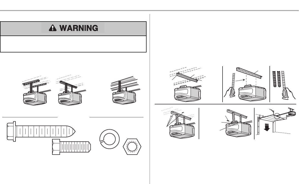
STEP 5 Hang the garage door opener
To avoid possible SERIOUS INJURY from a falling garage door opener,fasten it SECURELY to
structural supports ofthe garage. Concrete anchors MUSTbe used if installing ANY brackets into
masonry.
Hanging the garage door opener will varydepending on your garage.Beloware three example
installations. Your installation maybe different.For ALL installations the garage door opener MUST be
connected to structural supports. The instructions illustrate one of the examples below.
Finished
Ceiling
Unfinished
Ceiling
HARDWARE
Hex Bolt 5/16"- 18x7/8"
Nut 5/16"-18
Lock Washer
5/16"-18
Lag Screw 5/16"-9x1-5/8"
1. On finished ceilings, use the lag screwsto attach a support bracket (not provided) to the structural
supports before installing the garage door opener.
2. Make sure the garage door opener isaligned with the header bracket.Measure the distance
from each side of the garage door opener to the support bracket.
3. Cutboth pieces of the hanging bracket to required lengths.
4. Attach the end ofeach hanging bracket to the supportbracketwith appropriate hardware (not
provided).
5. Attach the garage door opener to the hanging brackets with the hex bolts,lockwashers, and
nuts.
6. Remove the 2x4 and manuallyclose the door.If the door hits the rail,raise the header bracket.
Finished
Ceiling (not provided)
(not provided)
Lag Screw
5/16"-
9x1-5/8"
Lag Screw
5/16"-
9x1-5/8"
123
(not
provided)
Hex Bolt
5/16"- 18x7/8"
Nut 5/16"-18
Lock Washer
5/16"-18
456
14
Installation
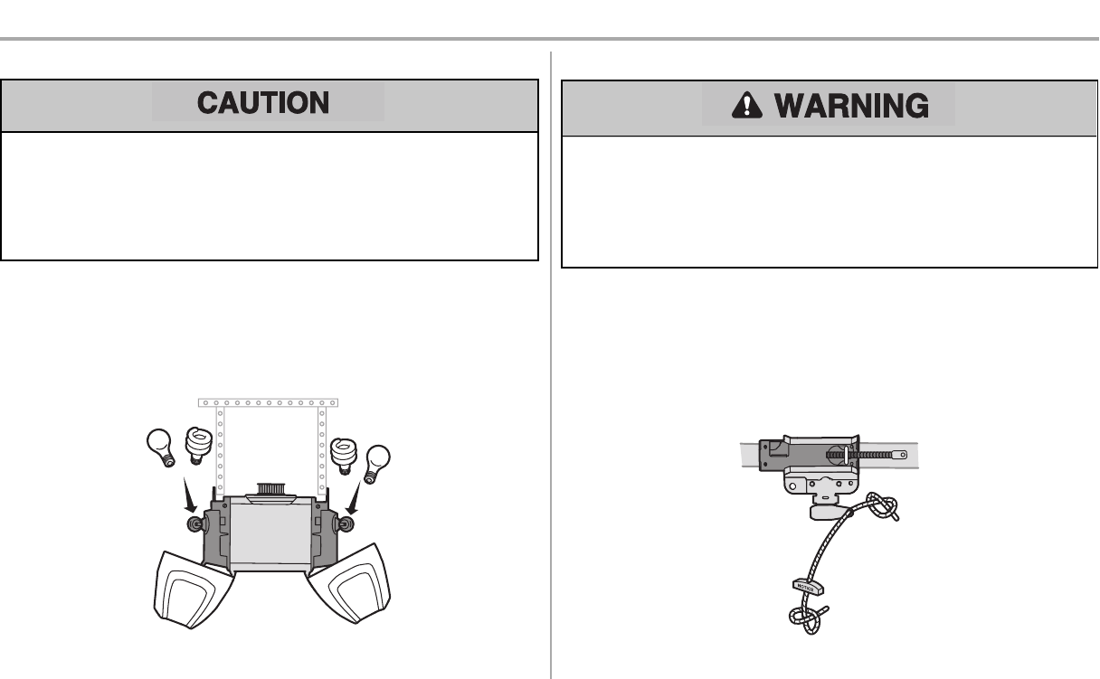
STEP 6 Install the light bulbs
To prevent possible OVERHEATING of the end panel or light socket:
lUse ONLY A19 incandescent(100W maximum) or compact fluorescent (26W maximum) light
bulbs.
lDO NOT use incandescent bulbs larger than 100W.
lDO NOT use compact fluorescent light bulbs larger than 26W (100W) equivalent.
lDO NOT use halogen bulbs.
lDO NOT use short neck or specialty light bulbs.
1. Pull on the top sides of the lightlensand rotate the light lens down.
2. Insert an A19 incandescent (100W maximum) or compact fluorescent (26W, 100W equivalent)
lightbulb into the light socket.
3. Rotate the lensup to close.
NOTE: Do not use halogen, short neck, or specialty light bulbs as these may overheat the end panel or
light socket. Do not use LED bulbs as they may reduce the range or performance of your remote controls.
or or
STEP 7 Attach the emergency release rope and handle
To prevent possible SERIOUS INJURY or DEATH from a falling garage door:
lIf possible,use emergency release handle to disengage trolley ONLY when garage door is
CLOSED. Weak or broken springs or unbalanced door could result in an open door falling
rapidlyand/or unexpectedly.
lNEVER use emergency release handle unless garage doorway is clear of persons and
obstructions.
lNEVER use handle to pull door open or closed. Ifrope knotbecomesuntied, you could fall.
1. Insert one end ofthe emergency release rope through the handle. Make sure that “NOTICE” is
rightside up. Tie a knot atleast1 inch (2.5 cm) from the end ofthe emergency release rope.
2. Insert the other end ofthe emergency release rope through the hole in the trolley release arm.
Mount the emergency release within reach, but at least 6 feet (1.83 m) above floor, avoiding
contact with vehicles to preventaccidental release and secure with a knot.
NOTE: If it is necessary to cut the emergency release rope, seal the cut end with a match or lighter to
prevent unraveling. Ensure the emergency release rope and handle are above the top of all vehicles to
avoid entanglement.
15
Installation
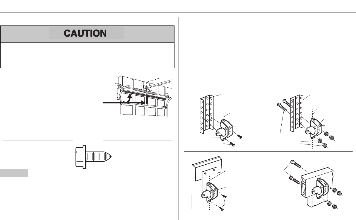
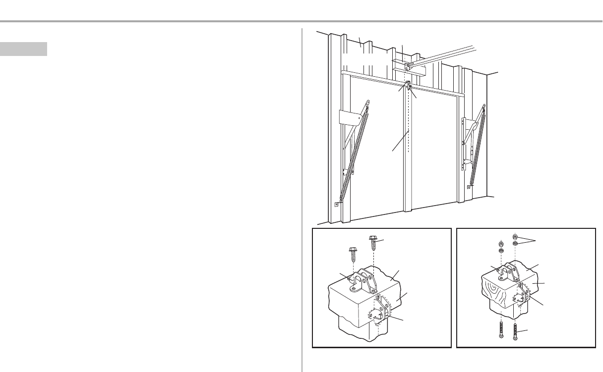
STEP 8 Install the door bracket
Fiberglass, aluminum or lightweight steel garage doors WILL REQUIRE reinforcement BEFORE
installation of door bracket. Contact the garage door manufacturer or installing dealer for opener
reinforcement instructions or reinforcementkit.Failure to reinforce the top section asrequired
according to the door manufacturer mayvoid the door warranty.
A horizontal and vertical reinforcement isneeded for
lightweight garage doors (fiberglass, aluminum, steel,
doors with glass panel, etc.) (not provided). A horizontal
reinforcement brace should be long enough to be
secured to two or three vertical supports. A vertical
reinforcement brace should cover the heightof the top
panel. Contact the garage door manufacturer or installing
dealer for opener reinforcement instructions or
reinforcement kit.
NOTE: Many door reinforcement kits provide for direct attachment of the clevis pin and door arm.In this
case you will not need the door bracket; proceed to the next step.
Self-Threading Screw
1/4"-14x5/8"
HARDWARE
OPTION A SECTIONAL DOORS
1. Center the door bracket on the previouslymarked vertical centerline used for the header bracket
installation. Note correct UP placement, as stamped inside the bracket.
2. Position the top edge ofthe bracket 2"-4" (5-10 cm) below the top edge of the door, ORdirectly
below any structural support acrossthe top of the door.
3. Mark, drill holes and install as follows, depending on your door’s construction.
Metal or light weight doors using a vertical angle iron brace between the door panel support and
the door bracket:
lDrill 3/16" fastening holes.Secure the door bracket using the two 1/4"-14x5/8" selfthreading
screws. (Figure 1)
lAlternately, use two 5/16"-18x2" bolts, lock washers and nuts (not provided). (Figure 2)
Metal, insulated or light weight factory reinforced doors:
lDrill 3/16" fastening holes. Secure the door bracketusing the self-threading screws. (Figure 3)
Wood Doors:
lUse top and bottom or side to side door bracket holes.Drill 5/16" holes through the door and
secure bracket with 5/16"-18x2" carriage bolts, lock washers and nuts (not provided). (Figure 4)
NOTE: The 1/4"-14x5/8" self-threading screws are not intended for use on wood doors.
FIGURE 1
FIGURE 3 FIGURE 4
FIGURE 2
Vertical
Reinforcement
Vertical Centerline
of Garage Door
UP
Door Bracket
Vertical Reinforcement
Vertical Centerline
of Garage Door
Hardware
(not provided)
Door Bracket
UP
Vertical
Centerline
of Garage
Door
UP
Vertical Centerline of
Garage Door
Hardware
(not provided)
UP
Inside Edge of Door or
Reinforcement Board
Self-Threading Screw
1/4"-14x5/8"
Self-Threading
Screw
1/4"-14x5/8"
16
Installation
STEP 8 Install the door bracket (continued)
OPTION B ONE-PIECE DOORS
1. Center the door bracket on the top of the door,in line with the header bracketas shown.
2. Mark either the left and right, or the top and bottom holes.
Metal Doors:
lDrill 3/16" pilot holes and fasten the bracket with the self-threading screwsprovided.
Wood Doors:
lDrill 5/16" holes and use 5/16"-18x2" carriage bolts, lock washers and nuts (not provided) or
5/16"x1-1/2" lag screws (notprovided) depending on your installation needs.
NOTE: The door bracket may be installed on the top edge of the door if required for your installation.
(Refer to the dotted line optional placement drawing.)
For a door with no exposed
framing, or for the optional
installation, use lag screws
5/16"x1-1/2" (not provided)
to fasten the door bracket.
Vertical
Centerline
of Garage
Door
Optional
Placement
of Door
Bracket
Door Bracket
Header Bracket
Header Wall
2x4 Support (Finished Ceiling)
Door
Bracket
Top of Door
(Inside Garage)
Top Edge of
Door
Optional
Placement
Optional
Placement
Top Edge
of Door
Top of Door
(Inside Garage)
Door
Bracket
Hardware
(not provided)
Hardware
(not provided)
Metal Door Wood Door
Self-Threading
Screw 1/4"-14x5/8"
17
Installation
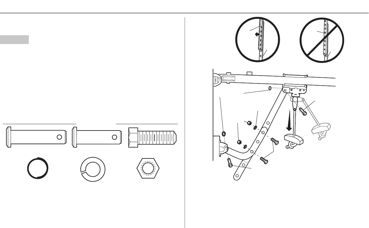
STEP 9 Connect the door arm to the trolley
Installation will vary according to the garage door type. Followthe instructions which applyto your door.
OPTION A SECTIONAL DOORS
IMPORTANT: The groove on the straight door arm MUSTface away from the curved door arm.
1. Close the door.Disconnectthe trolleyby pulling the emergencyrelease handle.
2. Attach the straightdoor arm to the outer trolley using the clevis pin. Secure with the ring fastener.
3. Attach the curved door arm to the door bracket using the clevis pin. Secure with the ring fastener.
4. Bring arm sections together.Find two pairs ofholes that line up and join sections.Selectholes as
far apart aspossible to increase door arm rigidityand attach using the bolts, nuts,and lock
washers.
5. Pull the emergencyrelease handle toward the garage door opener until the trolley release arm
is horizontal. The trolley will re-engage automatically when the garage door opener is activated.
NOTE: If the holes in the curved door arm and the straight door arm do not align, reverse the straight
door arm, select two holes (as far apart as possible) and attach using bolts , nuts, and lock washers . If the
straight door arm is hanging down too far, you may cut 6 inches (15 cm) from the solid end.
HARDWARE
Hex Bolt 5/16"-18x7/8"
Nut 5/16"-18
Lock Washer 5/16" -18
Clevis Pin 5/16"x1" Clevis Pin 5/16"x1-1/4"
Ring Fastener
Straight
Door Arm Curved
Door
Arm
(Groove
facing
out)
CORRECT
Straight
Door
Arm Curved
Door
Arm
INCORRECT
Lock Washer
5/16" -18
Nut
5/16"-18
Hex Bolt 5/16"-18x7/8"
Clevis Pin 5/16"x1-1/4"
Ring Fastener Clevis Pin
5/16"x1"
18
Installation
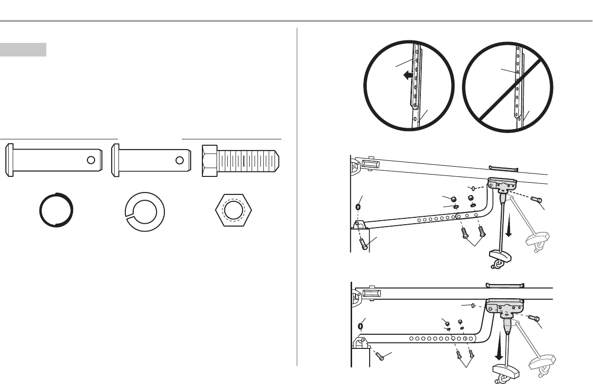
STEP 9 Connect the door arm to the trolley (continued)
OPTION B ONE-PIECE DOORS
IMPORTANT: The groove on the straight door arm MUSTface away from the curved door arm.
1. Close the door.Disconnectthe trolleyby pulling the emergencyrelease handle.
2. Fasten the straight door arm and the curved door arm together to the longest possible length
(with a 2 or 3 hole overlap) using the bolts, nuts,and lock washers.
3. Attach the straightdoor arm to the door bracketusing the clevispin.Secure with the ring fastener.
4. Attach the curved door arm to the trolley using the clevis pin. Secure with the ring fastener.
5. Pull the emergencyrelease handle toward the garage door opener until the trolley release arm
is horizontal.
HARDWARE
Hex Bolt 5/16"-18x7/8"
Nut 5/16"-18
Lock Washer 5/16" -18
Clevis Pin 5/16"x1" Clevis Pin 5/16"x1-1/4"
Ring Fastener
One-Piece Door without Track
One-Piece Door with Track
Straight
Door Arm
Curved
Door
Arm
(Groove
facing out)
CORRECT INCORRECT
Straight
Door
Arm
Curved
Door
Arm
Ring
Fastener Ring Fastener
Nut 5/16"-18
Nut 5/16"-18
Ring
Fastener
Ring Fastener
Lock Washer 5/16" -18
Lock Washer 5/16" -18
Clevis Pin 5/16"x1-1/4"
Clevis Pin
5/16"x1-1/4"
Hex Bolt 5/16"-18x7/8"
Hex Bolt 5/16"-18x7/8"
Clevis Pin
5/16"x1"
Clevis Pin
5/16"x1"
19
Installation
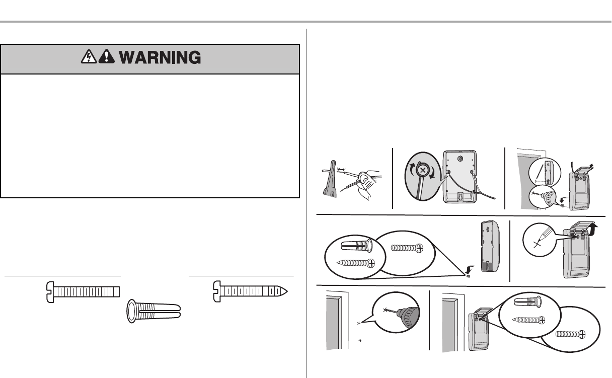
STEP 10 Install the door control
To prevent possible SERIOUS INJURY or DEATH from electrocution:
lBe sure power isNOT connected BEFORE installing door control.
lConnectONLY to 12 VOLT low voltage wires.
To prevent possible SERIOUS INJURY or DEATH from a closing garage door:
lInstall door control within sight of garage door, out of reach of children at a minimum height of 5
feet (1.5 m), and away from ALL moving parts of door.
lNEVER permitchildren to operate or playwith door control push buttons or remote control
transmitters.
lActivate door ONLY when it can be seen clearly,is properly adjusted, and there are no
obstructions to door travel.
lALWAYS keep garage door in sight until completely closed. NEVER permit anyone to cross path
of closing garage door.
INTRODUCTION
Older Chamberlain door controls and third partyproducts are not compatible. Install the door control
within sight ofthe door at a minimum heightof 5 feet (1.5 m) where small children cannotreach, and
away from the moving parts of the door. For gang box installations it is not necessary to drill holes or
install the drywall anchors. Use the existing holesin the gang box.
NOTE: Your product may look different than the illustrations.
HARDWARE
Screw
6ABx1" (2)
Drywall
Anchors (2)
Screw
6-32x1" (2)
1. Strip 7/16 inch (11 mm) of insulation from one end ofthe wire and separate the wires.
2. Connectone wire to each ofthe two screws on the backof the door control.The wires can be
connected to either screw.If your garage is pre-wired for the door control choose any two wires to
connect, note which wires are used so the correct wires are connected to the garage door
opener in a later step.
3. Mark the location ofthe bottom mounting hole and drill a 5/32 inch (4 mm) hole.
4. Install the bottom screw,allowing 1/8 inch (3 mm) to protrude from the wall.
5. Position the bottom hole of the door control over the screw and slide down into place.
6. Liftthe push bar up and markthe top hole.
7. Remove the door control from the wall and drill a 5/32 inch (4 mm) hole for the top screw.
8. Position the bottom hole of the door control over the screw and slide down into place.Attach the
top screw.
7/16" (11 mm) Wall
1 2 3
DRYWALL GANG BOX
6ABx1"
6-32x1"
Drywall Anchor
4-5 6
6-32x1"
GANG BOX
8 DRYWALL
6ABx1"
Drywall Anchor
7
20
Installation
STEP 11 Wire the door control to the garage door opener
HARDWARE
Insulated Staple
(Not Shown)
1. Run the white and red/white wire from the door control to the garage door opener. Attach the
wire to the wall and ceiling with the staple (notapplicable for gang box or pre-wired installations).
Do notpierce the wire with the staple as thismay cause a short or an open circuit.
2. Strip 7/16 inch (11 mm) of insulation from the end ofthe wire near the garage door opener.
3. Connectthe wire to the red and white terminals on the garage door opener.If your garage is pre-
wired make sure you use the same wires that are connected to the door control. To insert or
release wires from the terminal, push in the tab with screwdriver tip.
RED
WHITE
WHITE
GREY
7/16" (11 mm)
2
3
1
Staple
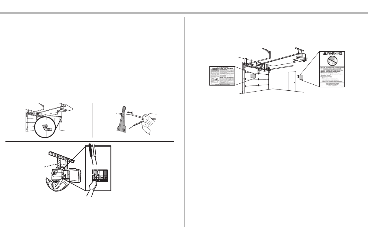
STEP 12 Attach the warning labels
1. Attach the entrapment warning label on the wall near the door control with tacks or staples.
2. Attach the manual release/safetyreverse testlabel in a visible location on the inside of the
garage door.
21
Installation
STEP 13 Install the Protector System®
Be sure power is NOT connected to the garage door opener BEFORE installing the safety reversing
sensor.
To prevent SERIOUS INJURY or DEATHfrom closing garage door:
lCorrectly connect and align the safety reversing sensor. This required safety device MUST NOT
be disabled.
lInstall the safetyreversing sensor so beam is NO HIGHERthan 6" (15 cm) above garage floor.
IMPORTANT INFORMATION ABOUT THE SAFETY REVERSING SENSORS
The safety reversing sensors must be connected and aligned correctly before the garage door
opener will move in the down direction.
The sending sensor (with an amber LED) transmits an invisible light beam to the receiving sensor (with a
green LED). Ifan obstruction breaks the light beam while the door is closing, the door will stop and
reverse to the full open position, and the garage door opener lightswill flash 10 times.
NOTE: For energy efficiency the garage door opener will enter sleep mode when the door is fully
closed. The sleep mode shuts the garage door opener down until activated. The sleep mode is
sequenced with the garage door opener light bulb; as the light bulb turns off the sensor LEDs will turn off
and whenever the garage door opener lights turn on the sensor LEDswill light. The garage door opener
will not go into the sleep mode until the garage door opener has completed 5 cycles upon power up.
When installing the safety reversing sensors check the following:
lSensorsare installed inside the garage, one on either side ofthe door.
lSensorsare facing each other with the lenses aligned and the receiving sensor lens does not
receive direct sunlight.
lSensorsare no more than 6 inches (15 cm) above the floor and the lightbeam is unobstructed.
Safety Reversing Sensor
6" (15 cm) max. above floor
Invisible Light Beam
Protection Area
Facing the door from inside the garage
HARDWARE
Carriage Bolt
1/4"-20x1/2" Wing Nut
1/4"-20
The safety reversing sensors can be attached to the door track, the wall, or the floor. The sensorsshould
be no more than 6 inches (15 cm) above the floor.If the door trackwill not supportthe sensor bracket a
wall installation is recommended. Choose one of the following installations.
OPTION A DOOR TRACK INSTALLATION
1. Slide the curved armsof the sensor bracket around the edge of the door track. Snap into place
so that the sensor bracket is flush against the track.
2. Slide the carriage bolt into the slot on each sensor.
3. Insert the boltthrough the hole in the sensor bracket and attach with the wing nut.The lenseson
both sensors should pointtoward each other.Make sure the lens is notobstructed bythe sensor
bracket.
No more
than 6 inches
(15 cm) Carriage Bolt
1/4"-20x1/2"
Wing Nut
1/4"-20
123
22
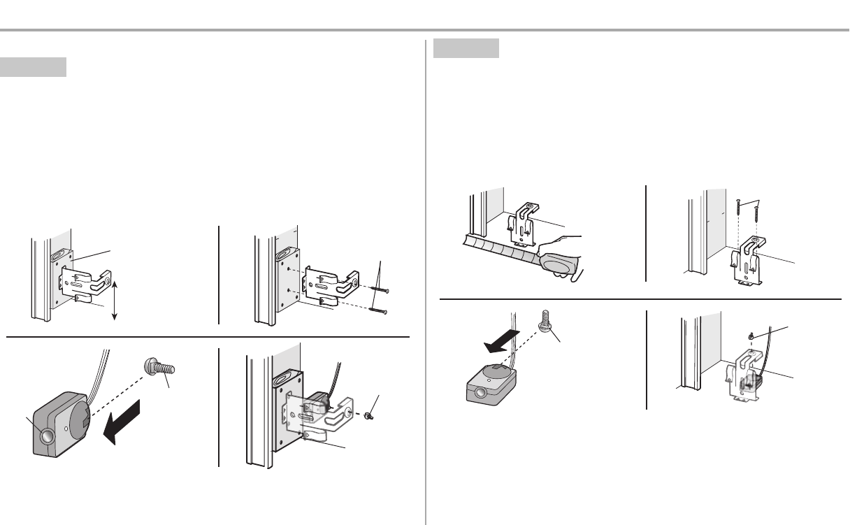
Installation
STEP 13 Install the Protector System®(continued)
OPTION B WALL INSTALLATION
If additional clearance isneeded an extension bracket (not provided) or wood blocks can be used. Make
sure each bracket has the same amount of clearance so they will align correctly.
1. Position the sensor bracket against the wall with the curved armsfacing the door. Make sure
there is enough clearance for the beamto be unobstructed. Mark holes.
2. Drill 3/16 inch pilot holes for each sensor bracket and attach the sensor bracketsto the wall using
lag screws (not provided).
3. Slide the carriage bolt into the slot on each sensor.
4. Insert the boltthrough the hole in the sensor bracket and attach with the wing nut.The lenseson
both sensors should pointtoward each other.Make sure the lens is notobstructed bythe sensor
bracket.
(Not provided)
No more than
6 inches (15 cm)
12
Inside
Garage
Wall
(Not provided)
Lens
Carriage Bolt
1/4"-20x1/2"
Wing Nut
1/4"-20
34
OPTION C FLOOR INSTALLATION
Use an extension bracket (notprovided) or wood block to raise the sensor bracket if needed.
1. Carefully measure the position of both sensor bracketsso they will be the same distance from the
wall and unobstructed.
2. Attach the sensor bracketsto the floor using concrete anchors (not provided).
3. Slide the carriage bolt into the slot on each sensor.
4. Insert the boltthrough the hole in the sensor bracket and attach with the wing nut.The lenseson
both sensors should pointtoward each other.Make sure the lens is notobstructed bythe sensor
bracket.
Inside
Garage
Wall
(Not provided)
1 2
Carriage Bolt
1/4"-20x1/2"
Wing Nut
1/4"-20
34
23
Installation
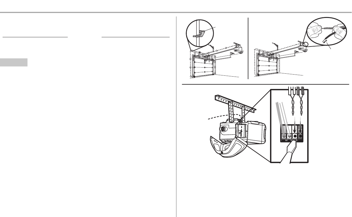
STEP 14 Wire the Safety Reversing Sensors
If your garage already has wires installed for the safety reversing sensors, proceed to page 24.
HARDWARE
Insulated Staple
(Not Shown)
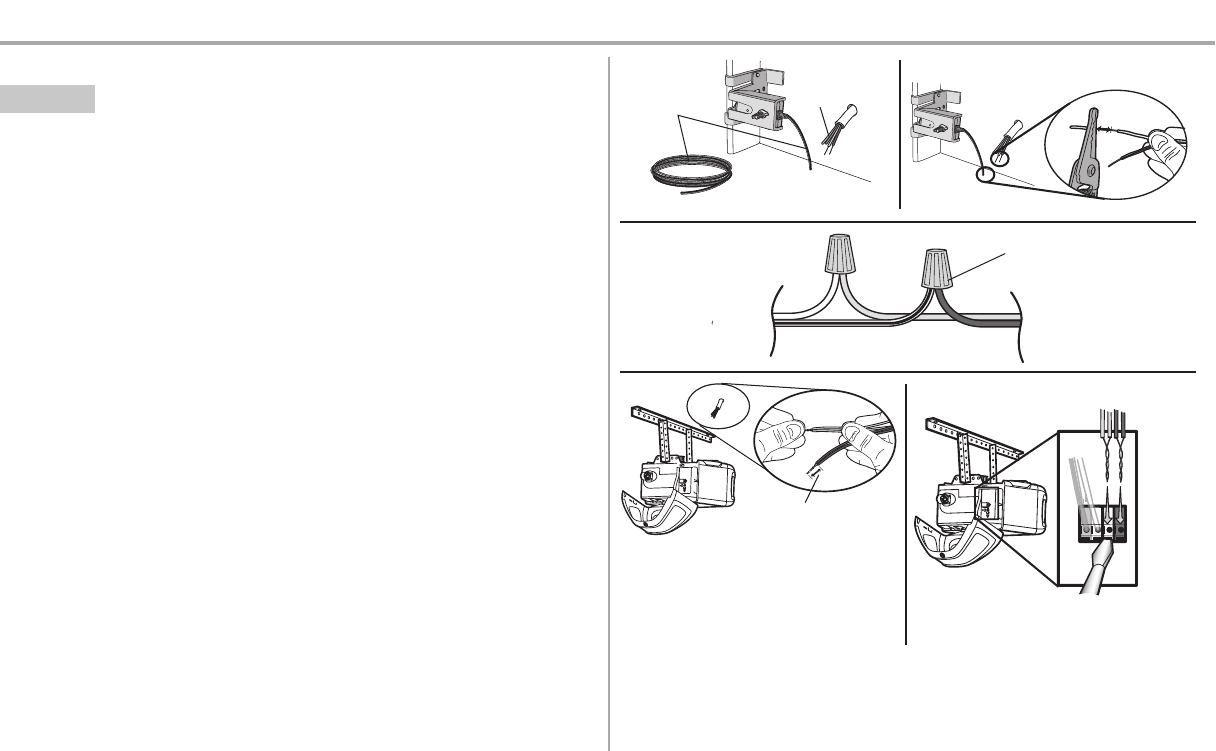
OPTION A INSTALLATION WITHOUT PRE-WIRING
1. Run the wire from both sensors to the garage door opener. Attach the wire to the wall and ceiling
with the staples.
2. Strip 7/16 inch (11 mm) of insulation from each set ofwires. Separate the wires. Twist the white
wires together. Twist the white/black wires together.
3. Insert the white wires into the white terminal on the garage door opener. Insert the white/black
wires into the grey terminal on the garage door opener. To insertor remove the wires from the
terminal, push in the tab with a screwdriver tip.
Staple
7/16" (11 mm)
WHITE
WHITE
GREY
RED
12
3
24
Installation
STEP 14 Wire the Safety Reversing Sensors (continued)
OPTION B PRE-WIRED INSTALLATION
1. Cutthe end of the safetyreversing sensor wire, making sure there is enough wire to reach the
pre-installed wires from the wall.
2. Separate the safetyreversing sensor wires and strip 7/16 inch (11 mm) of insulation from each
end.Choose two ofthe pre-installed wires and strip 7/16 inch (11 mm) of insulation from each
end.Make sure thatyou choose the same color pre-installed wires for each sensor.
3. Connectthe pre-installed wires to the sensor wireswith wire nutsmaking sure the colors
correspond for each sensor. For example, the white wire would connectto the yellow wire and
the white/black wire would connect to the purple wire.
4. At the garage door opener, strip 7/16 inch (11 mm) ofinsulation from each end of the wires
previously chosen for the safetyreversing sensors. Twistthe like-colored wires together.
5. Insert the wires connected to the white safety sensor wires to the white terminal on the garage
door opener. Insertthe wires that are connected to the white/blacksafetysensor wires to the grey
terminal on the garage door opener.
Safety reversing
sensor wires
Pre-installed
wires
White
White/Black
Yellow (for example)
Purple (for example)
Not Provided
Pre-installed wires
Safety reversing
sensor wires
7/16" (11 mm)
Yellow
Purple
1
3
4
7/16"
(11 mm)
2
WHITE
WHITE
RED
GREY
Purple
(for
example)
Yellow
(for example)
To insert or remove the wires from
the terminal, push in the tab with a
screwdriver tip.
5
25
Installation
STEP 15 Connect power
To preventpossible SERIOUS INJURY or DEATHfrom electrocution or fire:
lBe sure power is NOT connected to the opener, and disconnectpower to circuitBEFORE
removing cover to establish permanent wiring connection.
lGarage door installation and wiring MUST be in compliance with ALL local electrical and
building codes.
lNEVER use an extension cord,2-wire adapter,or change plug in ANY way to make itfit outlet. Be
sure the opener isgrounded.
To avoid installation difficulties, do not run the opener at this time.
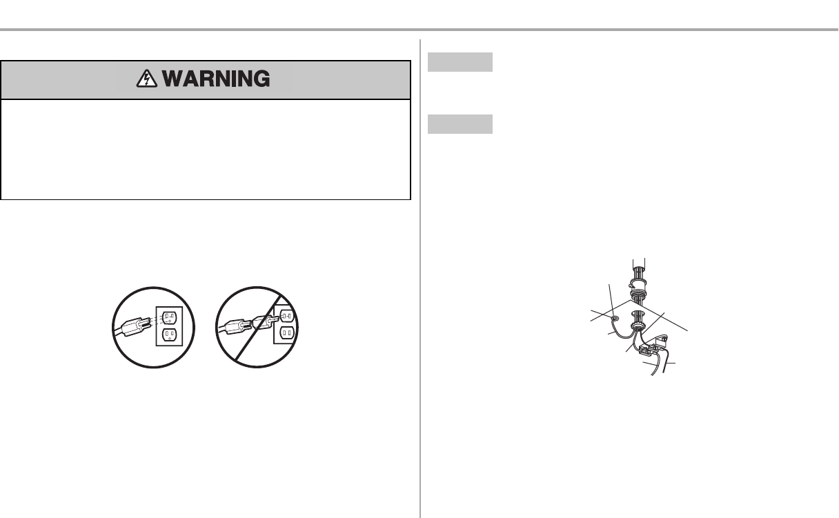
To reduce the risk ofelectric shock, your garage door opener has a grounding type plug with a third
grounding pin. This plug will only fit into a grounding type outlet. Ifthe plug doesn’tfit into the outletyou
have, contact a qualified electrician to install the proper outlet.
THERE ARE TWO OPTIONS FOR CONNECTING POWER:
OPTION A TYPICAL WIRING
1. Plug in the garage door opener into a grounded outlet.
2. DO NOT run garage door opener atthis time.
OPTION B PERMANENT WIRING
If permanent wiring is required by your local code, refer to the following procedure. To make a
permanent connection through the 7/8 inch hole in the top of the motor unit (according to local
code):
1. Remove the motor unit cover screwsand setthe cover aside.
2. Remove the attached 3-prong cord.
3. Connectthe black(line) wire to the screw on the brassterminal; the white (neutral) wire to the
screw on the silver terminal; and the ground wire to the green ground screw.The opener must
be grounded.
4. Reinstall the cover.
Ground Tab
Green
Ground
Screw
Ground
Wire
White Wire
Black
Wire
Black
Wire
26
Installation
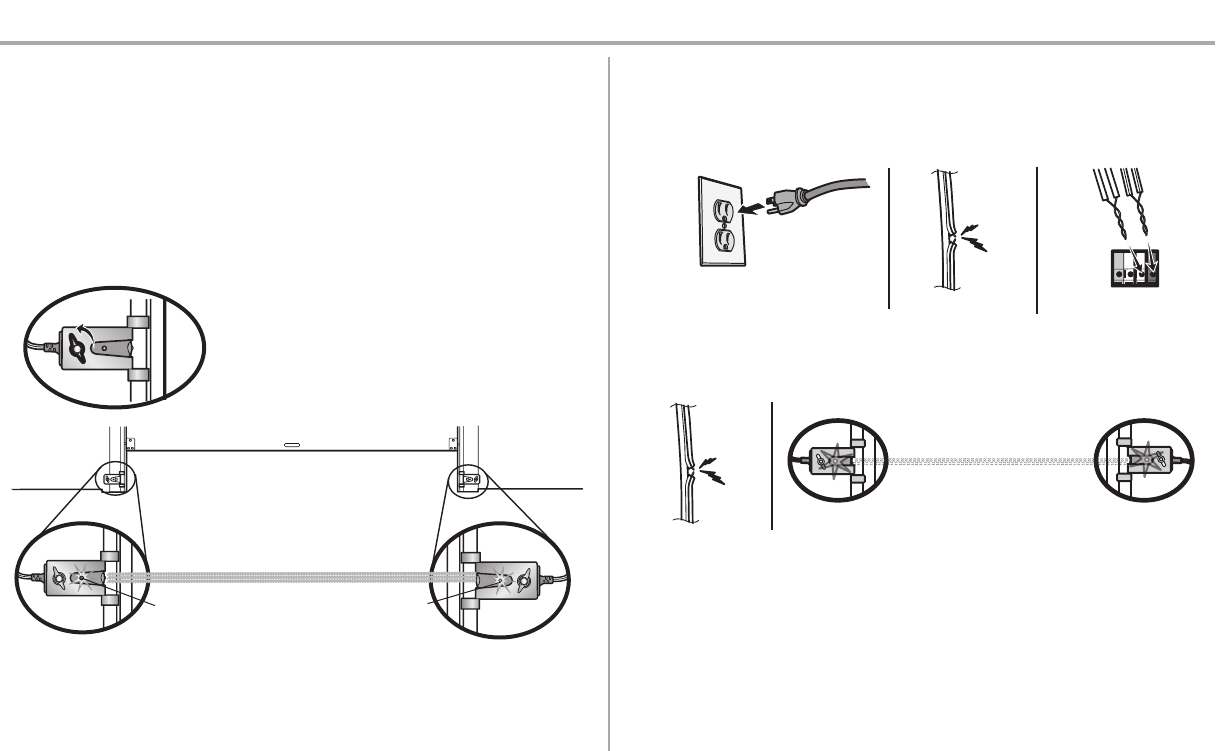
STEP 16 Aligning the safety reversing sensors
The door will not close if the sensors have not been installed and aligned correctly.
When the light beam isobstructed or misaligned while the door is closing, the door will reverse and the
garage door opener lights will flash ten times. If the door is already open, it will not close.
1. Check to make sure the LEDsin both sensors are glowing steadily.The LEDsin both sensorswill
glowsteadilyif they are aligned and wired correctly.
The sensorscan be aligned by loosening the wing nuts, aligning the sensors, and tightening the wing
nuts.
Green LED
Amber LED
If the receiving sensor is in direct sunlight,
switch it with sending sensor so it is on the
opposite side of the door.
(invisible light beam)
SENDING SENSOR RECEIVING SENSOR
IF THE AMBER LED ON THE SENDING SENSOR IS NOT GLOWING:
1. Make sure there is power to the garage door opener.
2. Make sure the sensor wire isnotshorted/broken.
3. Make sure the sensor has been wired correctly: white wiresto white terminal and white/black
wires to grey terminal.
RED
WHITE
WHITE
GREY
3
2
1
IF THE GREEN LED ON THE RECEIVING SENSOR IS NOT GLOWING:
1. Make sure the sensor wire isnotshorted/broken.
2. Make sure the sensors are aligned.
12
STEP 17 Ensure the door control is wired correctly
If the door control has been installed and wired correctly,a message will display on the SmartControl
Panel screen.
27
Adjustments
Introduction
Without a properly installed safety reversal system, persons (particularly small children) could be
SERIOUSLY INJURED or KILLED by a closing garage door.
lIncorrect adjustmentof garage door travel limits will interfere with proper operation ofsafety
reversal system.
lAfter ANY adjustmentsare made,the safety reversal system MUST be tested. Door MUST reverse
on contact with 1-1/2" (3.8 cm) high object (or 2x4 laid flat) on floor.
To prevent damage to vehicles, be sure fullyopen door provides adequate clearance.
Your garage door opener is designed with electronic controlsto make setup and adjustments easy.The
adjustments allow you to program where the door will stop in the open (UP) and close (DOWN) position.
The electronic controls sense the amount offorce required to open and close the door.The force is
adjusted automatically when you program the travel.
NOTE: If anything interferes with the door’s upward travel it will stop. If anything interferes with the door’s
downward travel, it will reverse.
UP (Open) DOWN (Close)
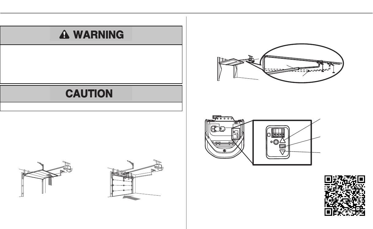
One-Piece Doors Only
When setting the UP travel for a one-piece door ensure that the door does not slant backwards when
fully open (UP). If the door is slanted backwards this will cause unnecessary bucking and/or jerking when
the door isopening or closing.
CORRECT
INCORRECT
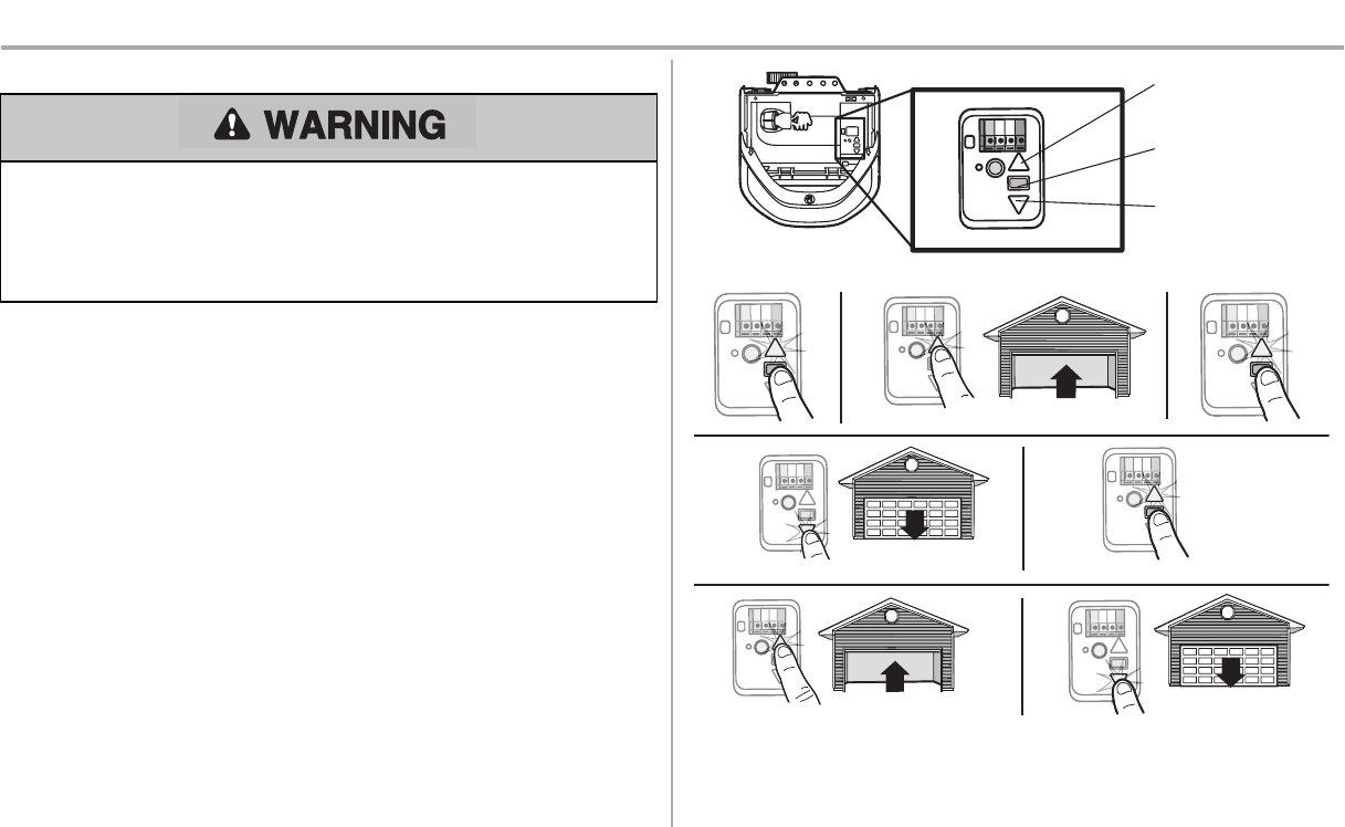
Programming Buttons
The programming buttons are located on the left side panel of the garage door opener and are used to
program the travel.While programming, the UP and DOWN buttons can be used to move the door as
needed.
UP Button
Adjustment Button
DOWN Button
PROGRAMMING BUTTONS
To watch a short instructional video on how to program the travel on your
new garage door opener use your smartphone to read the QRCode:
28
Adjustments
STEP 1 Program the Travel
Without a properly installed safety reversal system, persons (particularly small children) could be
SERIOUSLY INJURED or KILLED by a closing garage door.
lIncorrect adjustmentof garage door travel limits will interfere with proper operation ofsafety
reversal system.
lAfter ANY adjustmentsare made,the safety reversal system MUST be tested. Door MUST reverse
on contact with 1-1/2" (3.8 cm) high object (or 2x4 laid flat) on floor.
While programming, the UP and DOWN buttons can be used to move the door asneeded.
1. Press and hold the AdjustmentButton until the UP Button begins to flash and/or a beep is heard.
2. Press and hold the UP Button until the door is in the desired UP position.
3. Once the door is in the desired UP position press and release the AdjustmentButton. The
garage door opener lights will flash twice and the DOWN Button will begin to flash.IMPORTANT
NOTE: For one-piece door installations refer to page 27.
4. Press and hold the DOWNbutton until the door is in the desired DOWN position.
5. Once the door is in the desired DOWN position press and release the AdjustmentButton. The
garage door opener lights will flash twice and the UP Button will begin to flash.
6. Press and release the UP Button. When the door travels to the programmed UP position, the
DOWN Button will begin to flash.
7. Press and release the DOWN Button. The door will travel to the programmed DOWN position.
Programming is complete.
* Ifthe garage door opener lightsare flashing 5 times during the steps for Program the Travel,the
programming has timed out.If the garage door opener lightsare flashing 10 times during the steps for
Program the Travel,the safety reversing sensors are misaligned or obstructed (refer to page 26). When
the sensors are aligned and unobstructed, cycle the door through a complete up and down cycle using
the remote control or the UP and DOWNbuttons. Programming is complete.If you are unable to operate
the door up and down, repeatthe stepsfor Programming the Travel.
UP Button
Adjustment Button
DOWN Button
PROGRAMMING BUTTONS
1 2 3
4 5
6 7
29
Adjustments
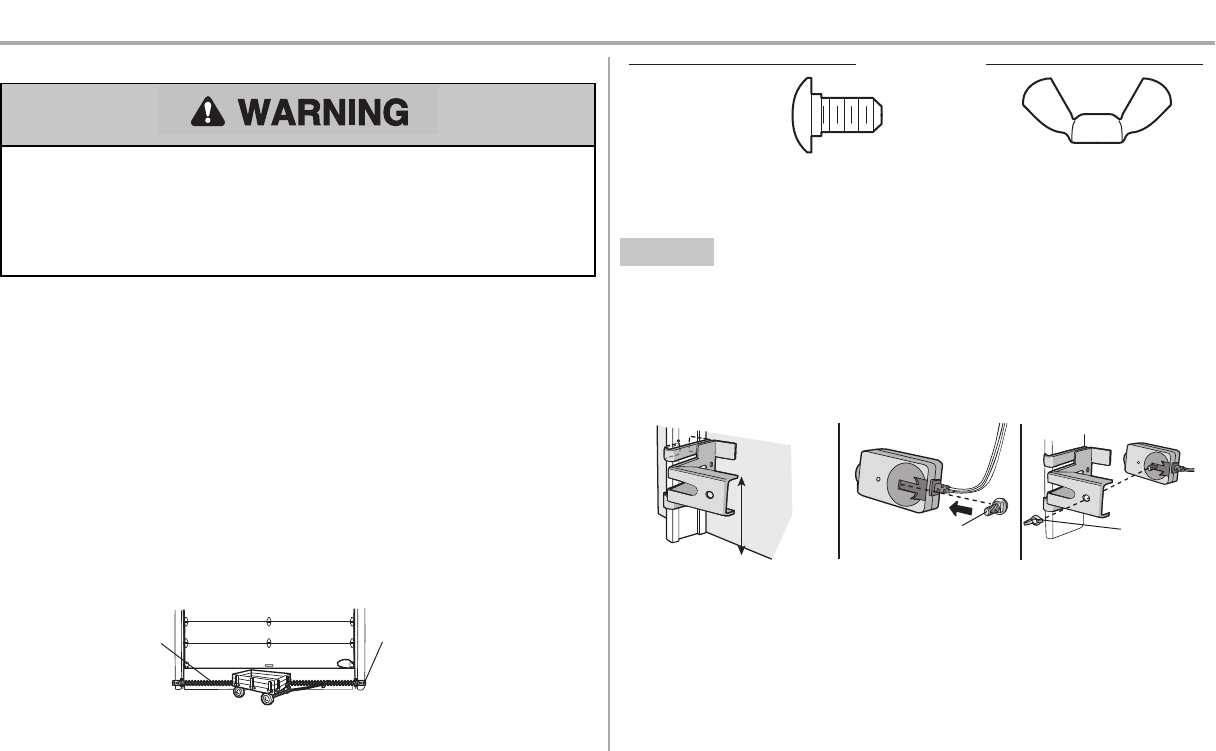
STEP 2 Test the Safety Reversal System
Without a properly installed safety reversal system, persons (particularly small children) could be
SERIOUSLY INJURED or KILLED by a closing garage door.
lSafety reversal system MUST be tested every month.
lAfter ANY adjustmentsare made,the safety reversal system MUST be tested. Door MUST reverse
on contact with 1-1/2" (3.8 cm) high object (or 2x4 laid flat) on the floor.
1. With the door fully open, place a 1-1/2 inch (3.8 cm) board (or a 2x4 laid flat) on the floor,
centered under the garage door.
2. Operate the door in the down direction. The door MUST reverse on striking the obstruction.
If the door stops and does not reverse on the obstruction,the down travel needsto be increased (refer to
AdjustmentStep 1). Repeatthe test. When the door reverses on the 1-1/2" (3.8 cm) board (or 2x4 laid
flat), remove the obstruction and run the opener through 3 or 4 complete travel cycles to test adjustment.
If the garage door opener continues to fail the safety reversal test,call a trained door systemstechnician.
1 2
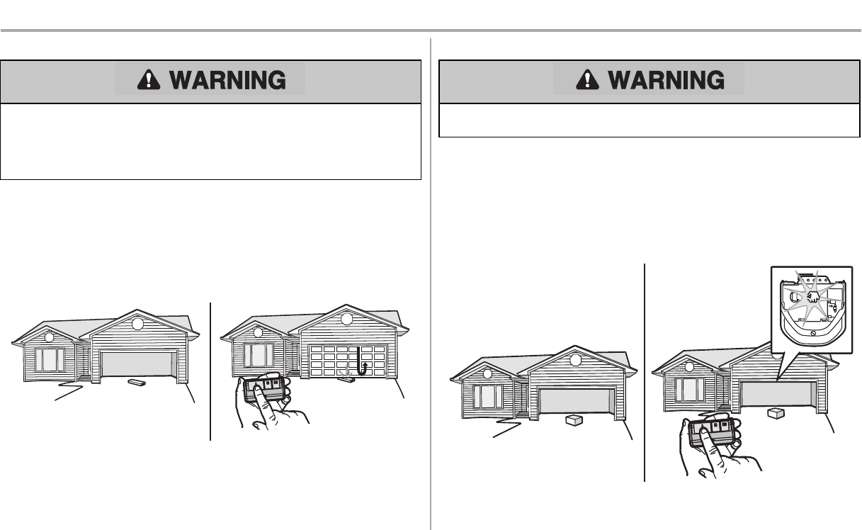
STEP 3 Test the Protector System®
Without a properly installed safety reversing sensor, persons (particularly small children) could be
SERIOUSLY INJURED or KILLED by a closing garage door.
1. Open the door. Place the garage door opener carton in the path of the door.
2. Press the remote control push button to close the door.The door will not move more than an inch
(2.5 cm),and the garage door opener lights will flash 10 times.
The garage door opener will not close from a remote control ifthe LED in either safetyreversing sensor
is off (alerting you to the fact that the sensor ismisaligned or obstructed). Ifthe garage door opener
closes the door when the safety reversing sensor is obstructed (and the sensors are no more than 6
inches [15 cm] above the floor), call for a trained door systemstechnician.
12
30
Battery Backup
STEP 1 Install the Battery
To reduce the risk ofFIRE or INJURY to persons:
lDisconnect ALL electric and battery power BEFORE performing ANY service or maintenance.
lUse ONLY Chamberlain part # 41A6357-1 for replacementbattery.
lDO NOT dispose of battery in fire. Battery may explode. Check with local codes for disposal
instructions.
ALWAYS wear protective gloves and eye protection when changing the battery or working around the
battery compartment.
The battery backup allowsaccessin and outof your garage, even when the power is out. The battery
doesnothave to be fully charged to operate the garage door opener. When the garage door opener is
operating on battery power,it will run slower and the battery status LED will glow solid orange,a beep
will sound approximately every 2 seconds.The following features are unavailable when operating on
battery power:
lGarage Door Opener Lights
lUnattended close devices and features (e.g. MyQ®Smartphone Control and Timer-to-Close)
Battery Status LED
1. Unplug the garage door opener.
2. Open the light lens on the right side panel of the garage door opener. Use a Phillipshead
screwdriver to remove the battery cover on the garage door opener.
3. Partiallyinsert the battery into the battery compartmentwith the terminals facing out.
4. Connectred (+) and black(-) wires from the garage door opener to the corresponding terminals
on the battery.
5. Replace the batterycover and plug in the garage door opener.
6. Waitfor the green Battery StatusLEDto start flashing before proceeding to testthe battery.
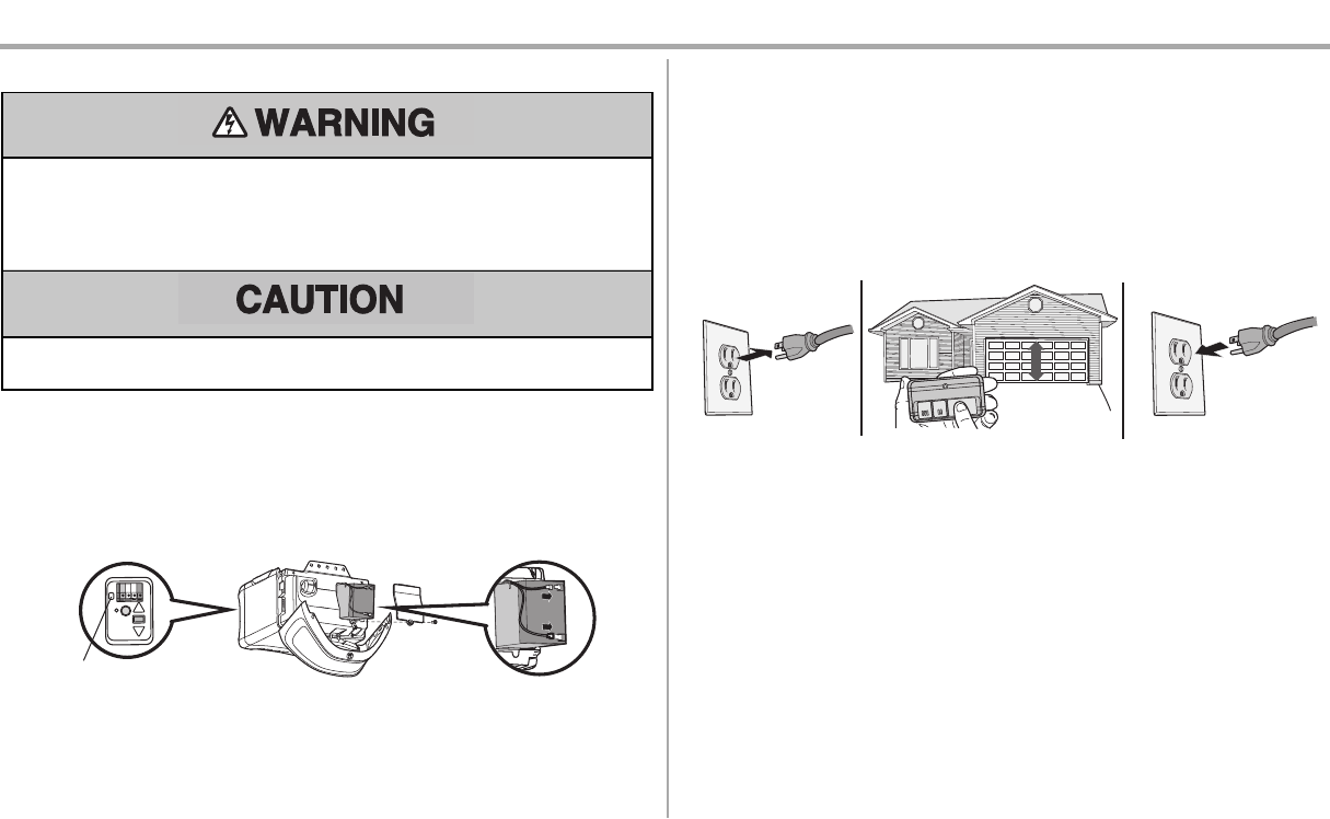
STEP 2 Test the Battery
1. Unplug the garage door opener. The battery status LED will glow solid orange indicating opener
is operating on battery power or will flash indicating low battery power.
2. Open and close the door using the remote control or door control.
3. Plug in the garage door opener. Verify the battery status LED is flashing green, indicating the
battery is charging.
1 2 3
Charge the Battery
The battery charges while the garage door opener is plugged into an electrical outlet. The battery
requires 24 hours to fully charge. A fully charged battery supplies 12Vdc to the garage door opener for
one to two days ofnormal operation during an electrical power outage. After the electrical power has
been restored,the battery will recharge within 24 hours.The battery will lastapproximately1 to 2 years
with normal usage. To obtain maximum battery life and prevent damage, disconnectthe battery when the
garage door opener isunplugged for an extended period of time,such asa summer or winter home.
31
IMPORTANT SAFETY INSTRUCTIONS
To reduce the risk of SEVERE INJURY or DEATH:
1. READ AND FOLLOW ALL WARNINGS AND INSTRUCTIONS.
2. ALWAYS keep remote controls out of reach of children. NEVER permit children to operate
or play with garage door control push buttons or remote controls.
3. ONLY activate garage door when it can be seen clearly,it is properly adjusted, and there
are no obstructions to door travel.
4. ALWAYS keep garage door in sightand awayfrom people and objectsuntil completely
closed.NO ONE SHOULD CROSS THE PATH OF THE MOVING DOOR.
5. NO ONE SHOULD GO UNDER A STOPPED, PARTIALLY OPENED DOOR.
6. If possible,use emergency release handle to disengage trolley ONLY when garage door is
CLOSED. Use caution when using thisrelease with the door open. Weakor broken
springsor unbalanced door could resultin an open door falling rapidly and/or unexpectedly
and increasing the risk ofSEVERE INJURY or DEATH.
7. NEVER use emergency release handle unless garage doorway is clear of persons and
obstructions.
8. NEVER use handle to pull garage door open or closed.If rope knot becomes untied, you
could fall.
9. After ANY adjustmentsare made,the safety reversal system MUSTbe tested.
10. Safetyreversal system MUST be tested every month. Garage door MUST reverse on contact with
1-1/2" (3.8 cm) high object(or a 2x4 laid flat) on the floor.Failure to adjustthe garage door
opener properly increases the risk of SEVERE INJURY or DEATH.
11. ALWAYS KEEP GARAGE DOOR PROPERLY BALANCED(see page 1). An improperly
balanced door may NOT reverse when required and could result in SEVERE INJURY or
DEATH.
12. ALL repairs to cables, spring assemblies and other hardware, ALL of which are under
EXTREME tension, MUST be made bya trained door systems technician.
13. ALWAYS disconnectelectricand battery power to garage door opener BEFORE making ANY
repairs or removing covers.
14. This operator system is equipped with an unattended operation feature. The door could move
unexpectedly.NO ONE SHOULD CROSS THE PATH OF THE MOVING DOOR.
15. DO NOTinstall on a one-piece door if using devices or features providing unattended close.
Unattended devices and features are to be used ONLY with sectional doors.
16. SAVE THESE INSTRUCTIONS.
Operation
32
Operation
Using your Garage Door Opener
lThe garage door opener can be activated with a wall-mounted door control, remote control,
wireless keyless entry, MyQ®Smartphone Control app or MyQ®Garage Door Monitor. When the
door is closed and the garage door opener is activated the door will open. Ifthe door sensesan
obstruction or is interrupted while opening the door will stop. When the door is in any position
other than closed and the garage door opener is activated the door will close. Ifthe garage door
opener sensesan obstruction while closing,the door will reverse.If the obstruction interruptsthe
sensor beam the garage door opener lights will blink 10 times. If the door is fully open, and the
safetyreversing sensorsare not installed, or are misaligned,the door will not close from a remote
control, TTC, or the MyQ®Smartphone Control app. However,you can close the door by holding
the button on the door control or the ENTER button on the keylessentryuntil the door is fully
closed.
lThe garage door opener light bulbs will turn on when the opener is initially plugged in; power is
restored after interruption, or when the garage door opener isactivated. The lightswill turn off
automatically after 4-1/2 minutes. The lights will turn on when someone enters through the open
garage door and the safety reversing sensor infrared beam is obstructed, see page 33.Use an
incandescent A19 light bulb (100 wattmaximum) or for maximum energy efficiencya 26W (100W
equivalent) compact fluorescent light (CFL) bulb. NOTE: Do not use halogen, short neck, or
specialty light bulbs as these may overheat the end panel or light socket. Do not use LED bulbs
as they may reduce the range or performance of your remote controls.
To Open the Door Manually
To prevent possible SERIOUS INJURY or DEATH from a falling garage door:
lIf possible,use emergency release handle to disengage trolley ONLY when garage door is
CLOSED. Weak or broken springs or unbalanced door could result in an open door falling
rapidlyand/or unexpectedly.
lNEVER use emergency release handle unless garage doorway is clear of persons and
obstructions.
lNEVER use handle to pull door open or closed. Ifrope knotbecomesuntied, you could fall.
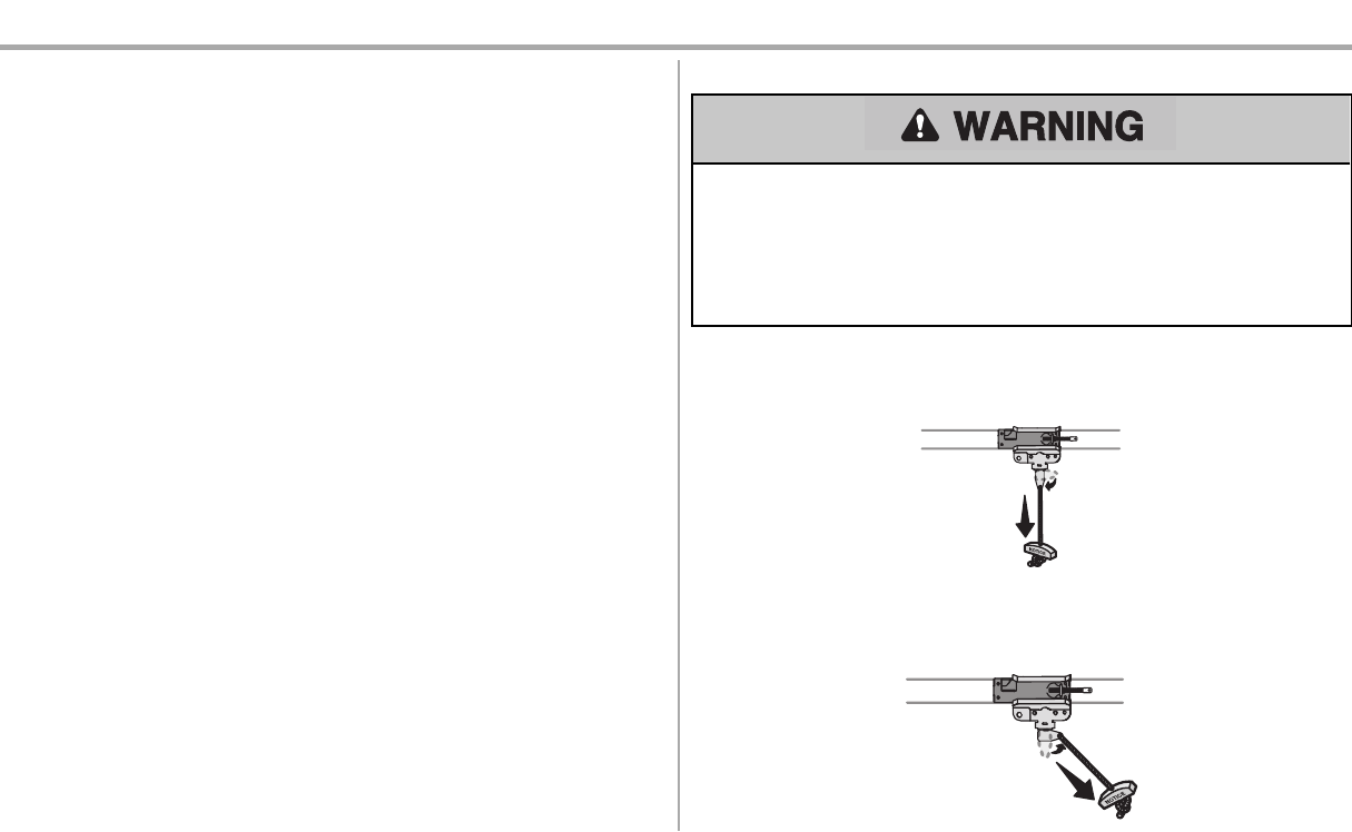
DISCONNECT THE TROLLEY
1. The door should be fully closed ifpossible.
2. Pull down on the emergencyrelease handle so the trolley release arm snaps to the vertical
position. The door can now be raised and lowered as often as necessary.
TO RECONNECT THE TROLLEY
1. Pull the emergencyrelease handle toward the garage door opener so the trolley release arm
snaps to the horizontal position. The trolley will reconnecton the nextUP or DOWN operation,
either manuallyor byusing the door control or remote control.
33
Operation
Door Control
SYNCHRONIZE THE DOOR CONTROL: To synchronize the door control to the garage door opener,
press the push bar until the garage door opener activates (it may take up to 3 presses). Testthe door
control by pressing the push bar; each pressof the push bar will activate the garage door opener.
Push Bar
LIGHT Button
Motion Sensor
Navigation Buttons
Screen
PUSH BAR: Press the push bar to open or close the door.
LIGHT BUTTON: Press the LIGHT button to turn the garage door opener lightson or off. When the lights
are turned on theywill stay on until the LIGHTbutton is pressed again, or until the garage door opener is
activated.Once the garage door opener isactivated the lightswill turn off after the specified period of
time (the factory default is 4-1/2 minutes).The LIGHT button will notcontrol the lights when the door isin
motion.The LightFeature will turn on the light on the garage door opener when someone enters
through the open garage door and the safety reversing sensor infrared beam isobstructed.
MOTION SENSOR: The motion sensor automatically turns on the garage door opener lights when
motion is detected. The lightscome on for the set period oftime, and then shutoff.If using the garage
door opener light as a work light disable the motion sensor, otherwise the lights may turn off automatically
if you are beyond the range ofthe motion sensor.
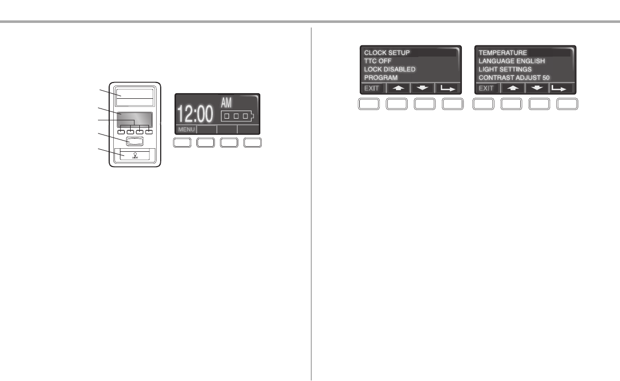
NAVIGATION AND SCREEN: The screen displays the time, temperature, and current battery charge (if
applicable) until the menu button is pressed, and then it will display the menu options.If there is a
problem with the garage doors opener the screen will display an error code (diagnosticcode, see page
37).The features on the door control can be programmed through a series of menus on the screen.Use
the navigation buttons to scroll through the menus and make selections.
MENU OPTIONS
CLOCK SETUP: Setthe time;choose 12 or 24 hour clock and show/hide clock.
TEMPERATURE: Display the temperature in Fahrenheit or Celsius and show/hide the temperature.
LANGUAGE: Select English, Spanish or French.
CONTRAST ADJUST: Adjust the screen contrast.
LIGHT SETTINGS:
To change the amount oftime the lightsstayon:
1. Select LIGHT SETTINGS from the menu.
2. Select LIGHT TIME.
3. Select the time interval.
To turn the LightFeature on or off(Factory defaultis On):
1. Select LIGHT SETTINGS from the menu.
2. Select AUTOMATIC LIGHTS.
3. Select ENTRY SENSOR.
To turn the motion sensor on or off:
1. Select LIGHT SETTINGS from the menu.
2. Select AUTOMATIC LIGHTS.
3. Select MOTION SENSOR.
LOCK: Prevents the garage door opener from being activated byremote controls while still allowing
activation from the door control and keyless entry.
To turn the LOCK feature ON or OFF:
1. Select LOCK fromthe menu. When the LOCK feature ison, a message displays on the screen.

34
Operation
MENU OPTIONS (CONTINUED)
TIMER-TO-CLOSE (TTC) (Factory default is set to off): The Timer-to-Close feature automatically
closes the door after a specified time period and can be adjusted using the door control. DO NOTenable
TTC if operating a one-piece door. TTC isto be used ONLY with sectional doors. The garage door
opener will beep and the lightswill flash before closing the door. The TTC feature will deactivate if the
garage door encounters an obstruction twice;or the safety reversing sensors are incorrectly installed.
The garage door will reverse open and WILL NOT close until the obstructionsare clear or the safety
reversing sensorsare correctly installed. When the obstruction has been cleared or the safetyreversing
sensors have been aligned, the door will close when the garage door opener is activated. TTC WILL
NOT work if the garage door opener is operating by battery power or if the safety reversing sensors are
misaligned. This feature is NOT intended to be the primary method of closing the door. A keyless entry
should be installed in the event of an accidental lockoutwhen using thisfeature.
To turn TTC on or offor to setthe TTC time interval:
1. Select TTC from the menu.
2. Select a time interval of1, 5,10 minutesor a custom setting up to 99 minutes. Once the TTC has
been set and the door is open, a message will display on the screen with the selected time
interval.
To temporarilysuspend the TTC feature select HOLD. SelectREL to resume normal TTCoperation.
PROGRAM: Any compatible remote control, wireless keyless entry, or MyQ®devices can be
programmed to the garage door using the PROGRAM option from the menu.
MyQ®Smartphone Control
Chamberlain MyQ®enabled garage door openersallowyou to control your garage door and your
house lights using your smartphone or tablet.You can program up to 10 MyQ®accessories to your
MyQ®account and 6 MyQ®accessoriesto the garage door opener.
Your garage door opener is capable of connecting to a Wi-Fi network to enable operation with MyQ®
Smartphone Control. You will need…
lRouter with Wi-Fi
lBroadband internetconnection
lPassword or SSID for your home network
lMyQ®serial number located on the garage door opener or the cover ofthis manual
lA strong Wi-Fi signal in the garage where the garage door opener will be installed, see page 2
lA smartphone or tablet
SETUP THE MyQ®SMARTPHONE CONTROL
1. Press the MENU button on the Smart Control Panel®.
2. Select the PROGRAM option from the menu. Then selectthe MyQ®option. A beep will be heard
from the garage door opener.
3. On your mobile device,go to Settings and turn on Wi-Fi.
4. Viewthe list ofavailable Wi-Fi networkson your mobile device and selectthe network with the
“MyQ-nnn prefix”.Once your mobile device isconnected,proceed to the next step.
5. Launch the web browser on your mobile device and the MyQ®setup page may automatically
load.If not, enter "setup.myqdevice.com". Once connected, follow the on-screen prompts to add
the garage door opener and download the MyQ®app.
6. Create your MyQ®account and add the MyQ®serial number to your account.
NOTE: Wi-Fi mode is enabled for 20 minutes and will automatically turn off if it is not connected. MyQ®
Smartphone Control WILL NOT work if the garage door opener is operating on battery power.
If you are replacing your router,moving,or removing the garage door opener from use and want to
erase the Wi-Fi settings see Erase the Memory page 35.
Go to wifihelp.chamberlain.comfor more details.
35
Operation
Remote Control and Keyless Entry
Your remote control has been programmed at the factory to operate with your garage door opener,
randomly accessing over 100 billion new codes with each use. Your garage door opener can be
programmed with up to 8 remote controls, 1 keyless entryand 2 Security+ 2.0™ door controls. Older
Chamberlain remote controls are NOTcompatible, see page 39 for compatible accessories.
Programming can be done through the door control or the learn button on the garage door opener.To
program additional accessories refer to the instructions provided with the accessory or visit
www.chamberlain.com. Ifyour vehicle isequipped with a Homelink®,you may require an external
adapter depending on the make, model, and year of your vehicle. Visit www.homelink.com for additional
information.
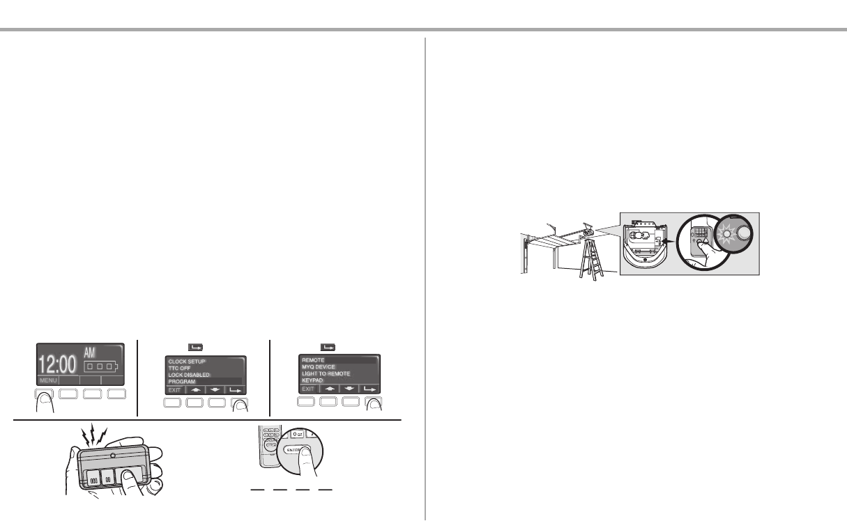
TO ADD, REPROGRAM, OR CHANGE A REMOTE CONTROL/KEYLESS ENTRY PIN
USING THE SMART CONTROL PANEL
1. Press the navigation button below "MENU" to view the Featuresmenu.
2. Use the navigation buttons to scroll to "PROGRAM".
3. Select "REMOTE" or "KEYPAD" to program from the program menu.
4. Remote Control: Pressthe button on the remote control thatyou wish to operate your garage
door.
Keyless Entry: Enter a 4-digitpersonal identification number (PIN) of your choice on the keyless
entry keypad. Then press the ENTER button.
The garage door opener lightswill flash (or two clicks will be heard) when the code has been
programmed. Repeat the steps for programming additional remote controls or keyless entry devices. If
programming is unsuccessful,repeat the steps using the learn button on the garage door opener.
12 3
OR
PIN
????
4
Press to continue. Press to continue.
To Erase the Memory
ERASE ALL REMOTE CONTROLS AND KEYLESS ENTRIES
1. Press and hold the LEARN button on garage door opener until the learn LEDgoesout
(approximately 6 seconds). All remote control and keyless entry codes are now erased.
Reprogram any accessory you wish to use.
ERASE ALL REMOTE CONTROLS, KEYLESS ENTRIES AND MyQ®DEVICES FROM
GARAGE DOOR OPENER
1. Press and hold the LEARN button on garage door opener until the learn LEDgoesout
(approximately 6 seconds).
2. Immediately press and hold the LEARNbutton again until the learn LED goes out. All codes are
now erased. Reprogram any accessory you wish to use.
ERASE THE CONNECTION FROM GARAGE DOOR OPENER TO HOME Wi-Fi
NETWORK
1. Press and hold the blackadjustmentbutton on the garage door opener until 3 beepsare heard
(Approximately 6 seconds).
ERASE A MyQ®ACCOUNT
1. Go to www.mychamberlain.com to access your MyQ®account.
2. Click on the "Account" tab.
3. Click "Edit User".
4. Click "Delete this account".
5. Click "Delete".
Go to wifihelp.chamberlain.comfor more details.
36
Maintenance
Maintenance Schedule
EVERY MONTH
lManuallyoperate door. Ifit is unbalanced or binding, call a trained door systems technician.
lCheck to be sure door opens and closes fully.Adjust ifnecessary,see page27.
lTest the safety reversal system. Adjust if necessary, see page27.
EVERY YEAR
lOil door rollers,bearings and hinges.The garage door opener does not require additional
lubrication.Do not grease the door tracks.
lTest the battery backup and consider replacing the battery to ensure the garage door opener will
operate during an electrical power outage, see page 30 to test the battery backup.
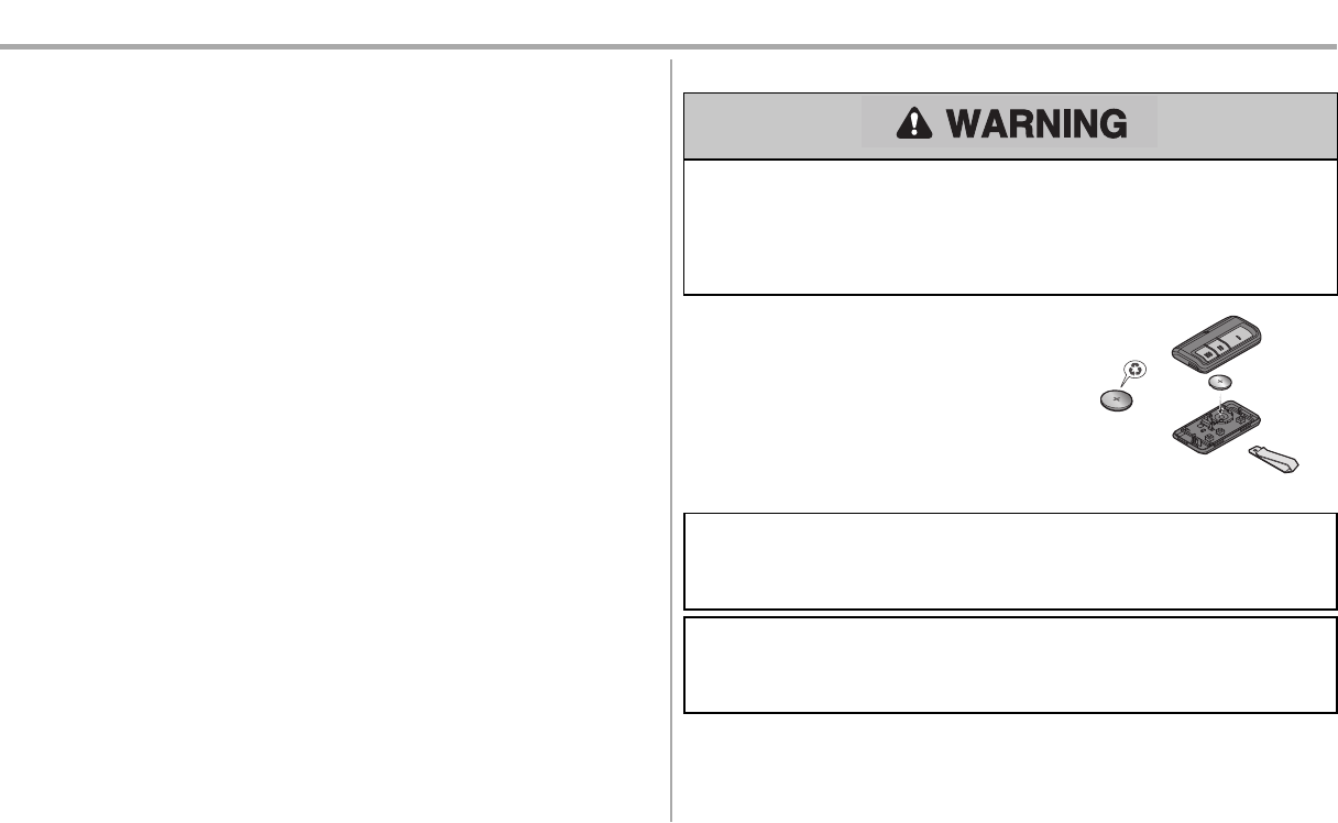
The Remote Control Battery
To prevent possible SERIOUS INJURY or DEATH:
lNEVER allow small children near batteries.
lIf battery is swallowed, immediately notify doctor.
To reduce risk of fire, explosion or chemical burn:
lReplace ONLY with 3V CR2032 coin batteries.
lDO NOT recharge, disassemble, heat above 212°F (100°C) or incinerate.
The 3V CR2032 lithium battery should produce power for
up to 3 years.If the battery islow,the remote control’s LED
will not flash when the button is pressed.
To replace battery,pry open the case first in the middle (1),
then at each side (2 and 3) with the visor clip. Replace the
batteries with only3V CR2032 coin cell batteries.Insert
battery positive side up. Dispose of old batteries properly.
1
2
3
NOTICE: To comply with FCC and/or Industry Canada (IC) rules, adjustment or modificationsof this transceiverare prohibited. THERE
ARENOUSER SERVICEABLEPARTS.
Thisdevice complieswith Part 15 of the FCC rulesand IC RSS-210. Operation issubjectto the following two conditions: (1)thisdevice
maynot cause harmfulinterference, and (2) thisdevice must accept anyinterference received, including interference that maycause
undesiredoperation.
Thisdevice mustbe installed in a waywhere a minimum8"(20cm)distance ismaintained between users/bystandersand device.
AVIS:Lesrèglesde la FCC et/ou d’Industrie Canada (IC)interdisent tout ajustement ou toute modification de ce récepteur. IL N’EXISTE
AUCUNEPIÈCESUSCEPTIBLED’ÊTREENTRETENUEPAR L’UTILISATEUR.
Cet appareilest conforme auxdispositionsde la partie 15 du règlement de la FCC et de l'norme IC RSS-210. Son utilisation est assujettie
aux deux conditoins suivantes: (1)ce dispositif ne peut causer desinterférencesnuisibles, et (2)ce dispositif doit accepter toute
interférence recue, ycomprisune interférence pouvant causer un fonctionnement non souhaité.
Cet appareildoitêtre installé de manière à laisserune distance d’au moins20 cm(8 po) entre celui-ciet l’utilisateurou toute personne.

37
Diagnostic Chart
Your garage door opener is programmed with self-diagnostic capabilities. The UP and DOWNarrows on the garage door opener flash the diagnosticcodes.
DIAGNOSTIC CODE SYMPTOM SOLUTION
Up Arrow
Flash(es)
Down Arrow
Flash(es)
1 1 The garage door opener will not close and the light bulbs flash. Safety sensors are not installed, connected, or wires may be cut. Inspect sensor wires for a disconnected
or cut wire.
1 2 The garage door opener will not close and the light bulbs flash. There is a short or reversed wire for the safety sensors. Inspect safety sensor wire atall staple and
connection points, replace wire or correct as needed.
1 3 The door control will not function. The wires for the door control are shorted or the door control is faulty. Inspect door control wires at all
staple and connection points,replace wire or correct as needed.
1 4 The garage door opener will not close and the light bulbs flash.
Safety sensors are misaligned or were momentarily obstructed. Realign both sensors to ensure both
LEDs are steady and not flickering. Make sure nothing ishanging or mounted on the door that would
interruptthe sensor’s path while closing.
1 5 Door moves 6-8" stops or reverses.
Manuallyopen and close the door.Check for binding or obstructions,such as a broken spring or door
lock, correct as needed. Check wiring connections at travel module and at the logic board. Replace travel
module if necessary.
No movement, only a single click. Manually open and close the door. Checkfor binding or obstructions,such as a broken spring or door
lock, correct as needed. Replace logic board if necessary.
Opener hums for 1-2 seconds no movement. Manuallyopen and close the door.Check for binding or obstructions,such as a broken spring or door
lock, correct as needed. Replace motor if necessary.
1 6 Door coastsafter it hascome to a complete stop. Program travel to coasting position or have door balanced by a trained door systems technician.
2 1-5 No movement, or sound. Replace logic board.
3 2 Unable to set the travel or retain position. Check travel module for proper assembly,replace if necessary.
3 3 The battery status LED is constantly flashing green. Battery backup charging circuit error, replace the logic board.
4 1-4 Door is moving stops or reverses. Manuallyopen and close the door.Check for binding or obstructions,such as a broken spring or door
lock, correct as needed. If the door is binding or sticking contact a trained door systems technician. If door
is not binding or sticking attemptto reprogram travel (refer to page 27).
Troubleshooting

38
DIAGNOSTIC CODE SYMPTOM SOLUTION
Up Arrow
Flash(es)
Down Arrow
Flash(es)
4 5 Opener runs approximately 6-8", stops and reverses. Communication error to travel module. Check travel module connections, replace travel module if
necessary.
4 6 The garage door opener will not close and the light bulbs flash. Safety sensors are misaligned or were momentarily obstructed. Realign both sensors to ensure both
LEDs are steady and not flickering. Make sure nothing ishanging or mounted on the door that would
interruptthe sensor’s path while closing.
The garage door opener can beep for several reasons:
lOperating on battery power or the 12 Vdc battery needs to be replaced,see page 30.
lGarage door opener hasbeen activated through a device or feature such as Timer-to-Close or
garage door monitor,see page 32.
My remote control will not activate the garage door:
lVerify the lock feature is not activated on the door control.
lReprogram the remote control.
lIf the remote control will still not activate the door checkthe diagnosticcodes to ensure the garage
door opener is working properly.
My door will not close and the light bulbs blink on my motor unit:
The safety reversing sensor must be connected and aligned correctly before the garage door opener
will move in the down direction.
lVerify the safety sensors are properly installed, aligned and free of any obstructions.
My garage door opener light(s) will not turn off when the door is open:
The garage door opener is equipped with a feature that turns the lighton when the safety reversing
sensors have been obstructed or when the motion sensor on the door control detectsmovement in the
garage.These features can be disabled using the door control,see page 33.
My neighbor’s remote control opens my garage door:
Erase the memory from your garage door opener and reprogram the remote control(s).
The LEDs on the door controlblink:
If you have a Smart Control Panel installed and the TTCis set to a custom time,press the ON button on
the Premium Motion-Detecting Control Panel to set the time properly.
My vehicle's Homelink®is not programming to my garage door opener:
Depending on the make, model, and year ofyour vehicle an external adapter maybe required. Visit
www.homelink.com for additional information.
Wi-Fi troubleshooting
If your black adjustment button is notsolid green go to wifihelp.chamberlain.com.
Green battery status LED - All systems are normal:
lA solid green LED light indicates the battery is fully charged.
lA flashing green LED indicates the battery is being charged.
Orange battery status LED - The garage door opener has lost power and is in battery backup mode:
lA solid orange LED with beep, sounding approximately every2 seconds, indicates the garage door
opener isoperating on battery power.
lA flashing orange LED with beep, sounding every 30 seconds, indicates the battery is low.
Red battery status LED - The garage door opener's 12V battery needs to be replaced:
lA solid red LED with beep, sounding every30 seconds,indicatesthe 12V battery will no longer hold
a charge and needs to be replaced.Please call for replacement battery to allow your system to
operate during a power outage.
Battery Status LED
Troubleshooting
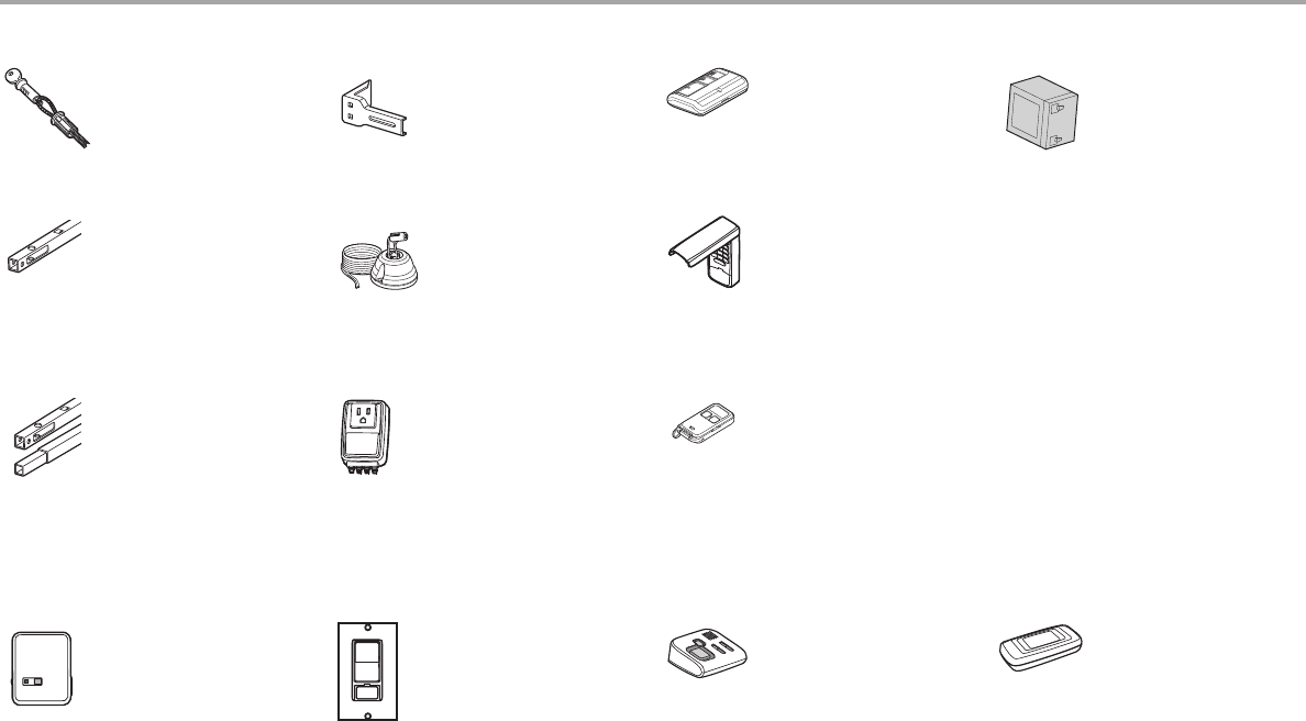
39
Accessories
CLLP1
953EV
CLSS1
Laser Parking Assistant:
Park in the right spot every time!
A laser beam is activated by your
garage door opener and
projected on to the dashboard
of your vehicle to guide perfect
parking.
Remote Control:
Works with ALL Chamberlain
openers from 1993-present.
MyQ® compatible. Includes visor
clip.
System Surge Protector:
The Garage Door Opener Surge
Protector is designed to protect
Chamberlain garage door
openers against damage from
lightning and power surges. Easy
to install.
AGDMEV MyQ® Garage Door Monitor:
Monitor open/closed status for
up to 4 MyQ® compatible garage
door openers or gate operators
and close them from anywhere in
the home.
956EV Keychain Remote Control:
Works with ALL Chamberlain
openers from 1993-present.
MyQ® compatible. With key ring.
940EV Wireless Keypad:
For use outside of the home to
enable access to the garage
using a 4-digit PIN. Works with
ALL Chamberlain openers from
1993-present. MyQ® compatible.
PILCEV MyQ® Remote Lamp Control:
Monitor and control this plug
in lamp switch with the MyQ®
Smartphone App.
WSLCEV MyQ® Interior/Exterior Light
Switch
Monitor and control this wall
light switch with the MyQ®
Smartphone App.
Extension Brackets:
(Optional) For safety reversing
sensor installation onto the wall
or fl oor.
CLOSED
OPEN
041A5281-1
8810CB 10 Foot (3 m) Rail Extension:
To allow a 10 foot (3 m) door to
open fully.
8 Foot (2.4 m) Rail Extension:
To allow an 8 foot (2.4 m) door to
open fully.
8808CB
7702CB Outside Quick Release:
Required for a garage with NO
access door.
41A6357-1 Standby Power System
Battery:
Provides backup power to the
garage door opener.
CIGBU
MyQ® Accessories
MyQ® Internet Gateway:
Offers longer range wireless
signal than standard Wi-Fi. Plugs
into your home router as an
optional way to provide MyQ®
Smartphone Control for your
garage door opener and MyQ®
light controls.
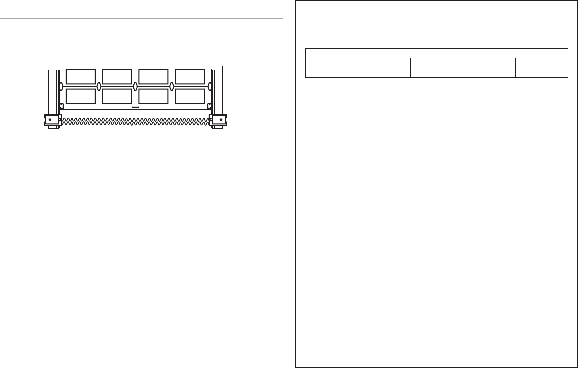
40
Warranty CHAMBERLAIN® LIMITED WARRANTY
The Chamberlain Group, Inc.® (“Seller”) warrants to the fi rst retail purchaser of this product, for the residence
in which this product is originally installed, that it is free from defects in materials and/or workmanship for a
specifi c period of time as defi ned below (the “Warranty Period”). The warranty period commences from the date
of purchase.
WARRANTY PERIOD
Parts Motor Accessories Belt Battery Backup
5 Years Lifetime 1 year Lifetime 1 year
The proper operation of this product is dependent on your compliance with the instructions regarding
installation, operation, and maintenance and testing. Failure to comply strictly with those instructions will void
this limited warranty in its entirety. If, during the limited warranty period, this product appears to contain a defect
covered by this limited warranty, call 1-800- 528-9131, toll free, before dismantling this product. You will be
advised of disassembly and shipping instructions when you call. Then send the product or component, pre-paid
and insured, as directed to our service center for warranty repair. Please include a brief description of the
problem and a dated proof- of-purchase receipt with any product returned for warranty repair. Products returned
to Seller for warranty repair, which upon receipt by Seller are confi rmed to be defective and covered by this
limited warranty, will be repaired or replaced (at Seller’s sole option) at no cost to you and returned pre-paid.
Defective parts will be repaired or replaced with new or factory rebuilt parts at Seller’s sole option. [You are
responsible for any costs incurred in removing and/or reinstalling the product or any component .]
ALL IMPLIED WARRANTIES FOR THE PRODUCT, INCLUDING BUT NOT LIMITED TO ANY IMPLIED
WARRANTIES OF MERCHANTABILITY AND FITNESS FOR A PARTICULAR PURPOSE, ARE LIMITED
IN DURATION TO THE APPLICABLE LIMITED WARRANTY PERIOD SET FORTH ABOVE FOR THE
RELATED COMPONENT(S), AND NO IMPLIED WARRANTIES WILL EXIST OR APPLY AFTER SUCH
PERIOD. Some States and Provinces do not allow limitations on how long an implied warranty
lasts, so the above limitation may not apply to you. THIS LIMITED WARRANTY DOES NOT COVER
NON-DEFECT DAMAGE, DAMAGE CAUSED BY IMPROPER INSTALLATION, OPERATION OR CARE
(INCLUDING, BUT NOT LIMITED TO ABUSE, MISUSE, FAILURE TO PROVIDE REASONABLE AND
NECESSARY MAINTENANCE, UNAUTHORIZED REPAIRS OR ANY ALTERATIONS TO THIS PRODUCT),
LABOR CHARGES FOR REINSTALLING A REPAIRED OR REPLACED UNIT, REPLACEMENT OF
CONSUMABLE ITEMS (E.G., BATTERIES IN REMOTE CONTROL TRANSMITTERS AND LIGHT BULBS),
OR UNITS INSTALLED FOR NON-RESIDENTIAL USE. THIS LIMITED WARRANTY DOES NOT COVER
ANY PROBLEMS WITH, OR RELATING TO, THE GARAGE DOOR OR GARAGE DOOR HARDWARE,
INCLUDING BUT NOT LIMITED TO THE DOOR SPRINGS, DOOR ROLLERS, DOOR ALIGNMENT
OR HINGES. THIS LIMITED WARRANTY ALSO DOES NOT COVER ANY PROBLEMS CAUSED BY
INTERFERENCE. UNDER NO CIRCUMSTANCES SHALL SELLER BE LIABLE FOR CONSEQUENTIAL,
INCIDENTAL OR SPECIAL DAMAGES ARISING IN CONNECTION WITH USE, OR INABILITY TO USE,
THIS PRODUCT. IN NO EVENT SHALL SELLER’S LIABILITY FOR BREACH OF WARRANTY, BREACH
OF CONTRACT, NEGLIGENCE OR STRICT LIABILITY EXCEED THE COST OF THE PRODUCT COVERED
HEREBY. NO PERSON IS AUTHORIZED TO ASSUME FOR US ANY OTHER LIABILITY IN CONNECTION
WITH THE SALE OF THIS PRODUCT.
Some states and provinces do not allow the exclusion or limitation of consequential, incidental or special
damages, so the above limitation or exclusion may not apply to you. This limited warranty gives you specifi c
legal rights, and you may also have other rights, which vary from state to state and province to province.
Contact Information
For installation and service information, please visit:
www.chamberlain.com/parts-and-support
If you are ordering a repair part please have the following information:
part number, part name, and model number.
Address repair parts orders to:
The Chamberlain Group, Inc.
6050 S. Country Club Road
Tucson, AZ 85706
Register your new garage door opener at
www.prodregister.com/chamberlain
STOP!
This garage door opener WILL NOT work until the
safety reversing sensors are properly installed and aligned.
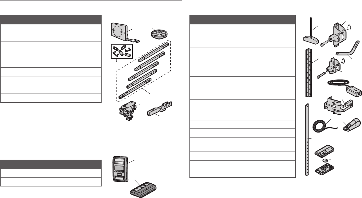
41
Repair Parts
Rail Assembly Parts
Accessories
Installation Parts
1
3
2
4
6
5
1
2
NOTICE
1
3
4
2
5
6
7
8
9
10
11
Description Part Number
1 Belt 41A5250
2 Pulley 144C54
3 Master Link 4A1008
4 Rail 41A5665
5 Trolley Assembly 41C5141-2
6 “U” Bracket 12D598-1
Not Shown
Wear Pads 183A163
Hardware Bag 041A7920-2
Description Part Number
1 Smart Control Panel® 41A7305-1
2 Remote Control 953ESTD
Description Part Number
1 Curved Door Arm 178B35
2 Door Bracket with Clevis
Pin and Fastener
41A5047-1
3 Emergency Release Rope
and Handle
41A2828
4 Header Bracket with
Clevis Pin and Fastener
41A5047-2
5 Remote Control
Visor Clip
29B137
6 Safety Sensor Bracket 041A5266-3
7 Safety Sensor Kit
Receiving and sending
sensors with wire
41A5034
8 Straight Door Arm 178B34
9 White and Red/White Wire 41B4494-1
10 3V CR2030 Lithium
Battery
10A20
11 Hanging Brackets 12B776
Not Shown
Owner’s Manual 114A4763
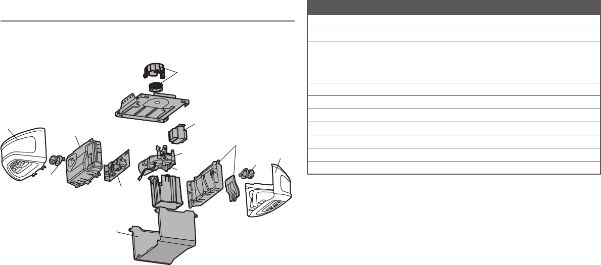
42
1
7
5
3
4
3
9
6
8
2
4
10
Repair Parts Description Part Number
1 Sprocket and Sprocket Cover with Screws 041C0589-2
2 End Panel with light socket 041D7639
3 Light Lens
Model WD1000WF
Model HD950WF
Model LW9000WF
041D7570
041D7572
041D7571
4 Light Socket 041C0279
5 Transformer 041D0277-1
6 Cover 041D0614-23
7 Motor with Travel Module 041D1739-1
8 End Panel for Receiver Logic Board with light socket 041D7638
9 Receiver Logic Board 050DCTWF
10 Travel Module 041A7114-7
Garage Door Opener Parts
© 2014, The Chamberlain Group, Inc.
All Rights Reserved
114A4763 Wi-Fi® is a registered trademark of Wi-Fi Alliance