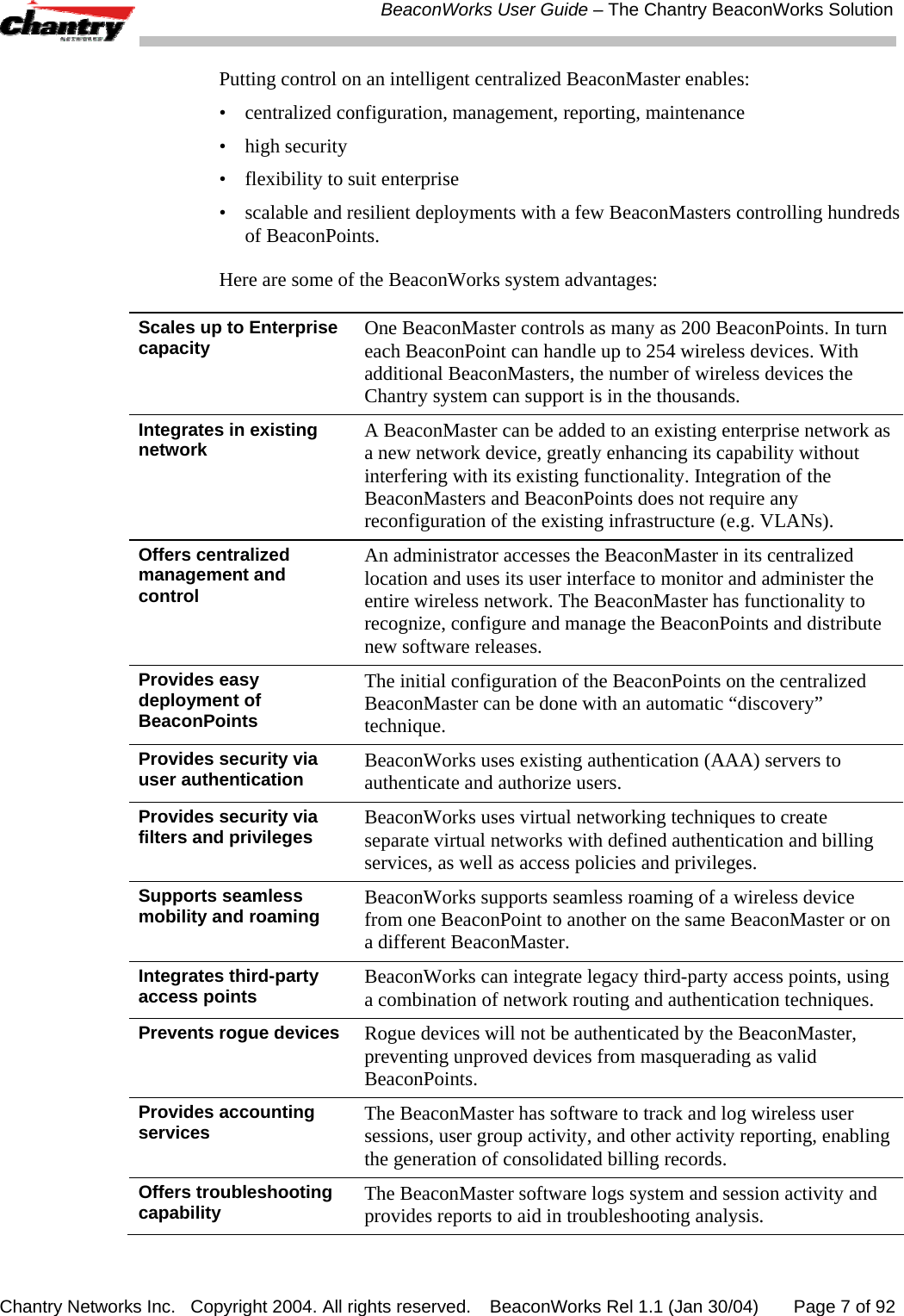
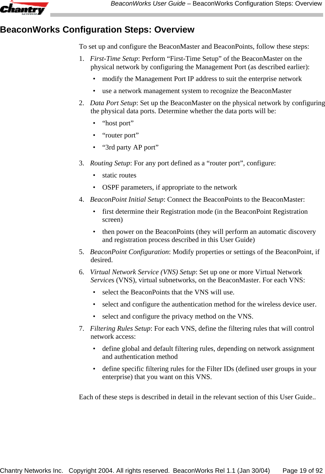
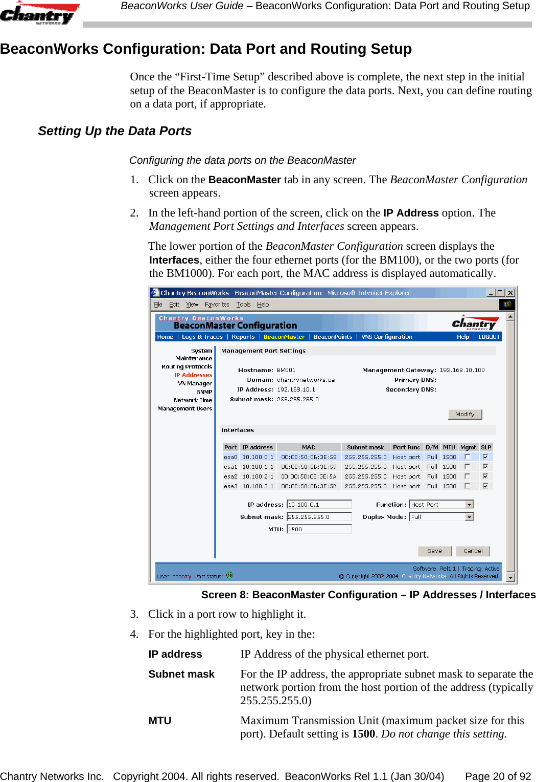
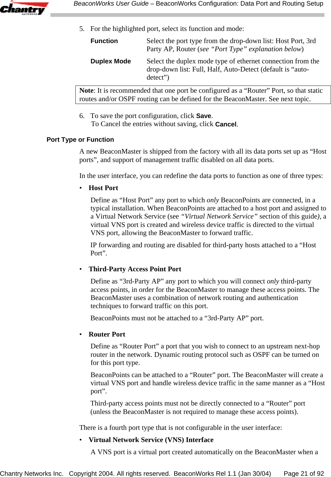
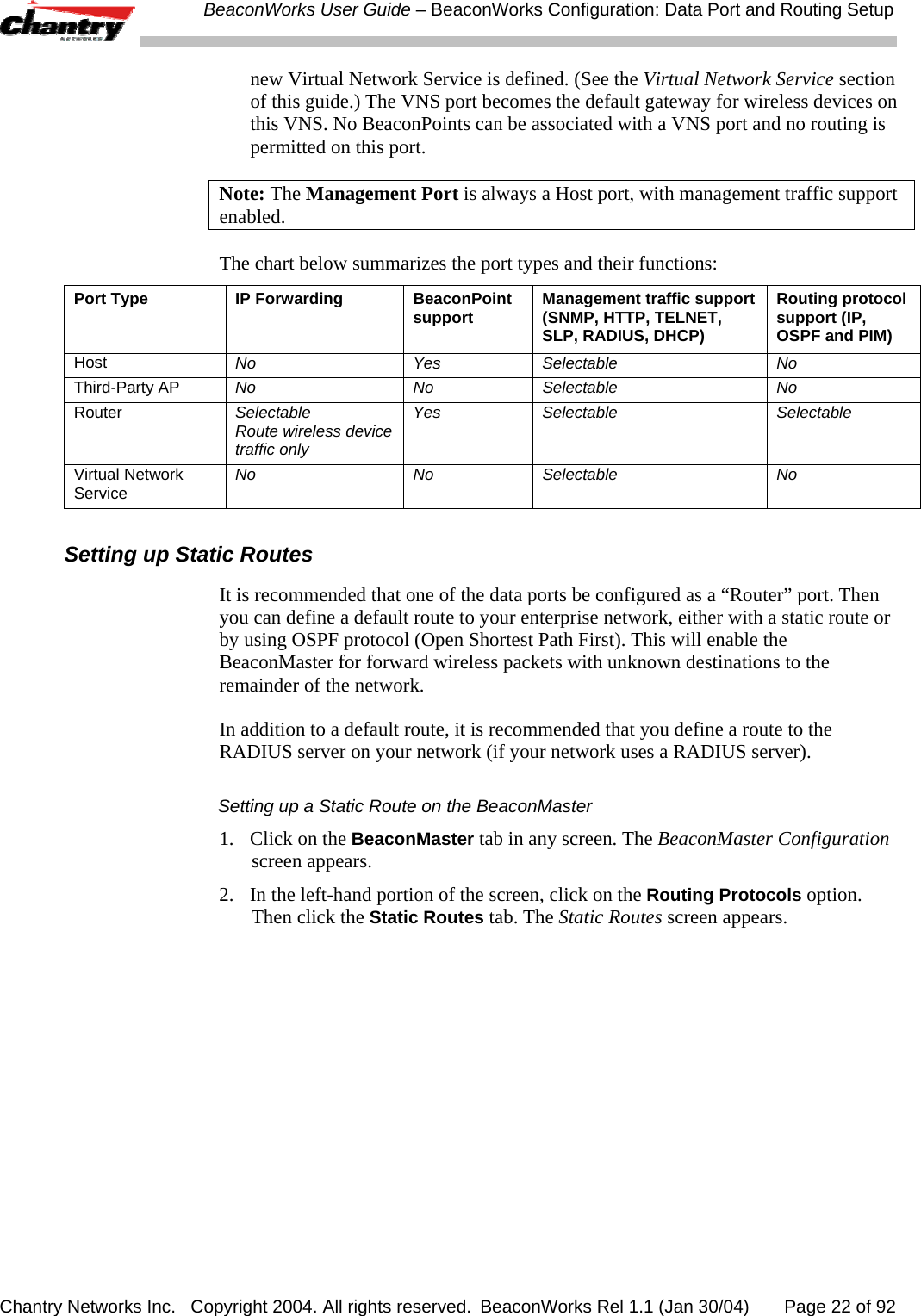
Chantry Networks BP200E Access Point with WLAN and UNII User Manual
Chantry Networks Inc. (a Siemens Company) Access Point with WLAN and UNII
UserManual.wiki
>
Chantry Networks
>
BP200E User Manual
>
users manual
Contents
1.
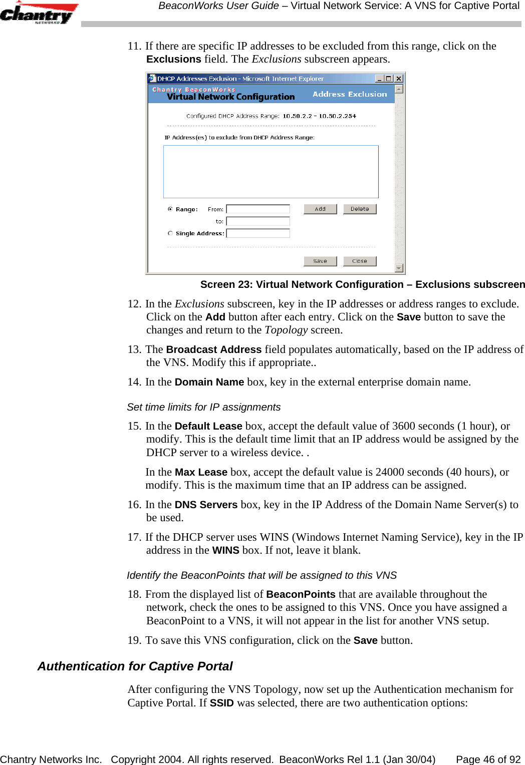
users manual
2.
users manual addendum
3.
quick start guide
4.
quick start guide addendum
5.
USERS MANUAL 1
6.
USERS MANUAL 2
7.
USER MANUAL 2
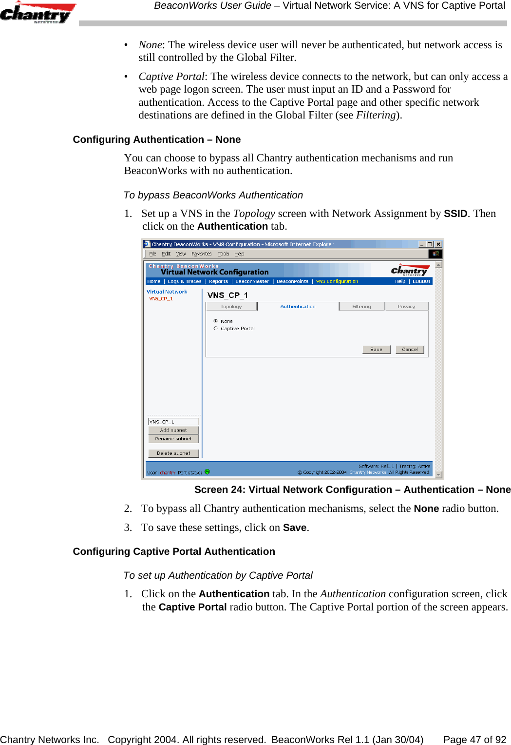
users manual
Navigation menu
Upload a User Manual
Namespaces
Wiki Guide
HTML
PDF
Info
Views
User Manual
Discussion / Help
Navigation
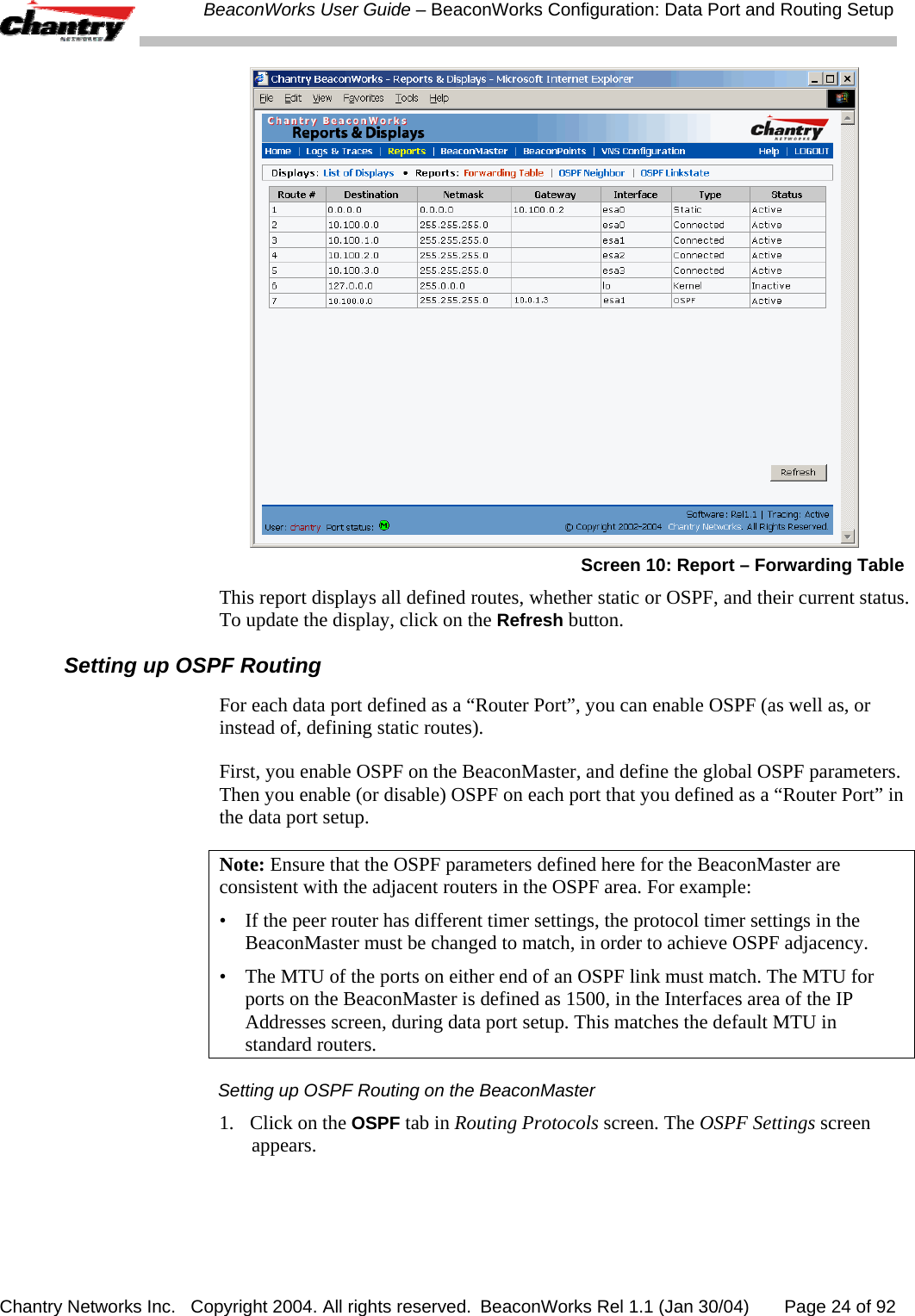
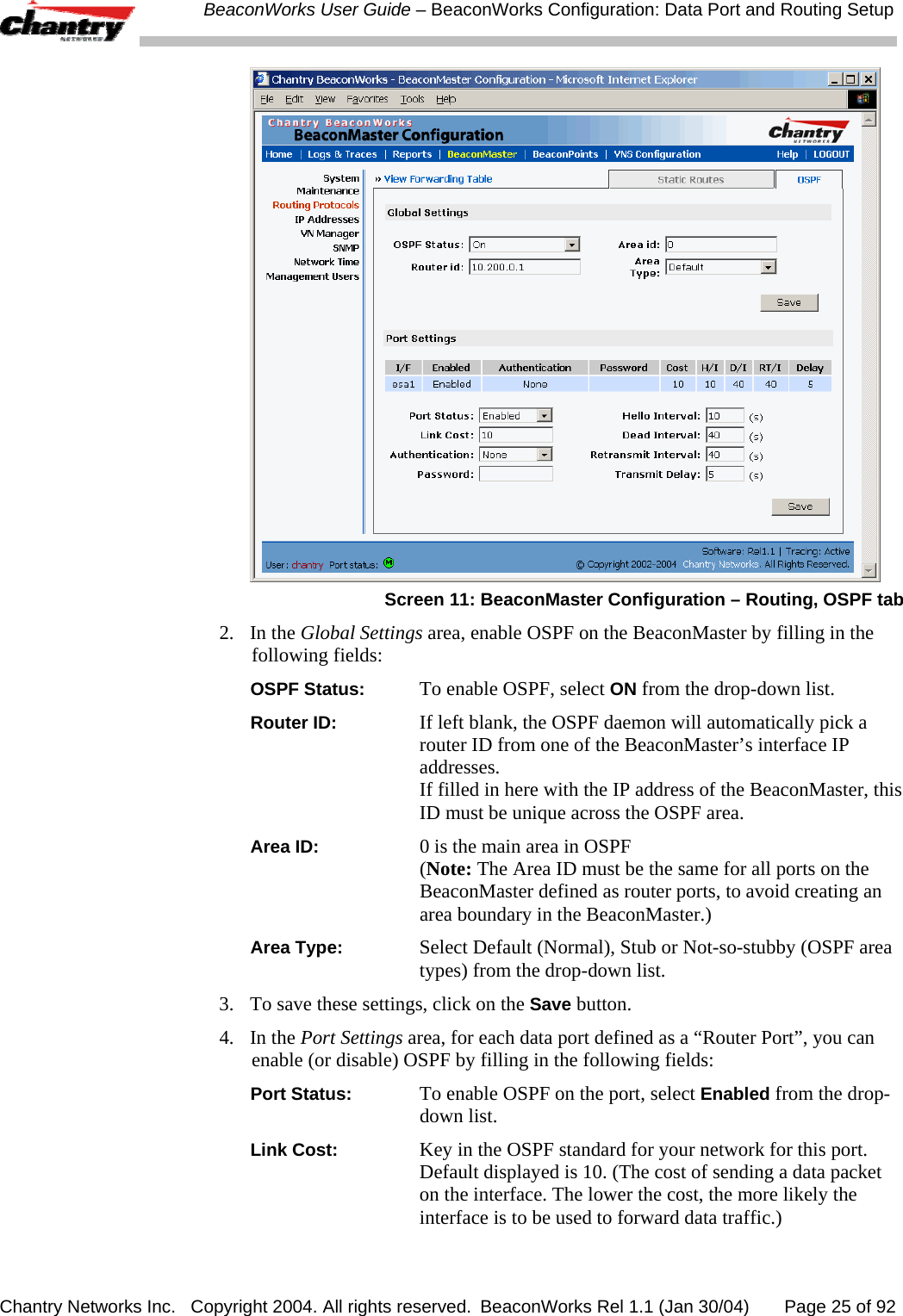
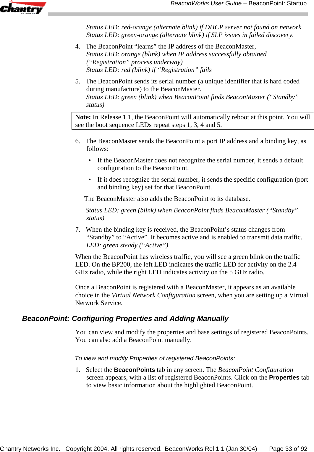
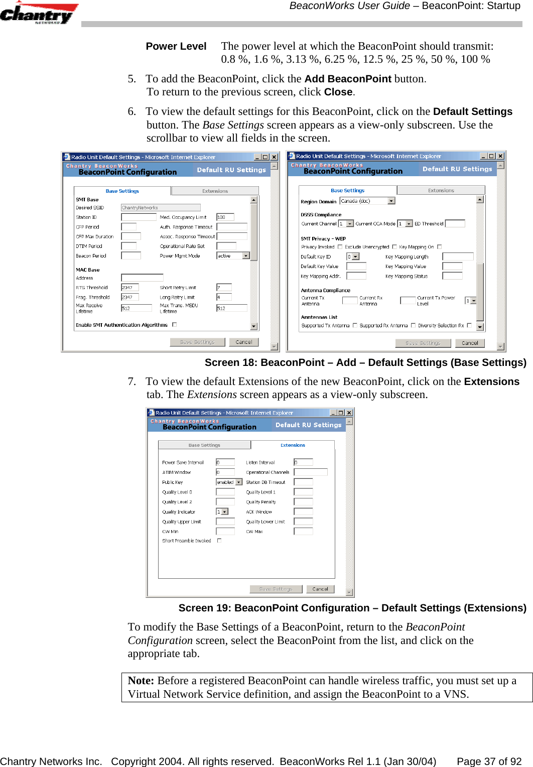
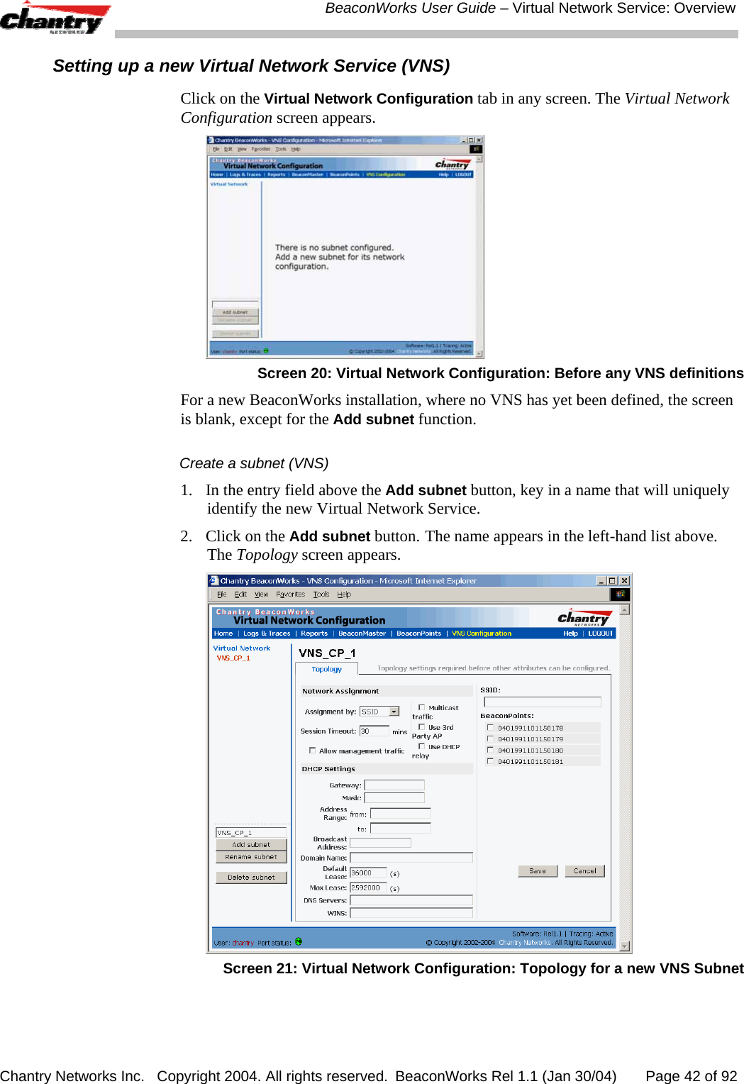
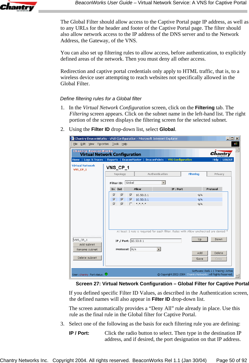
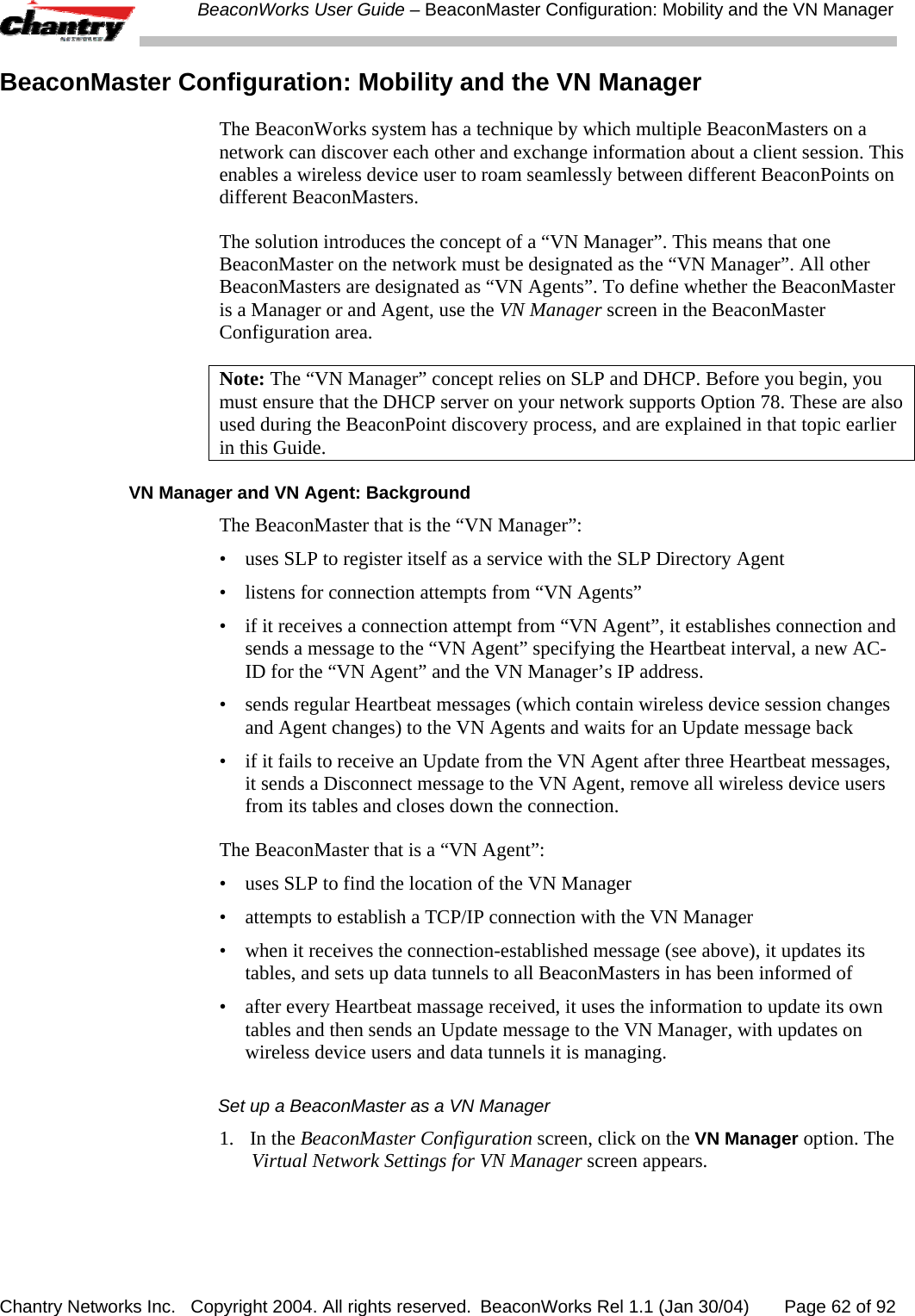
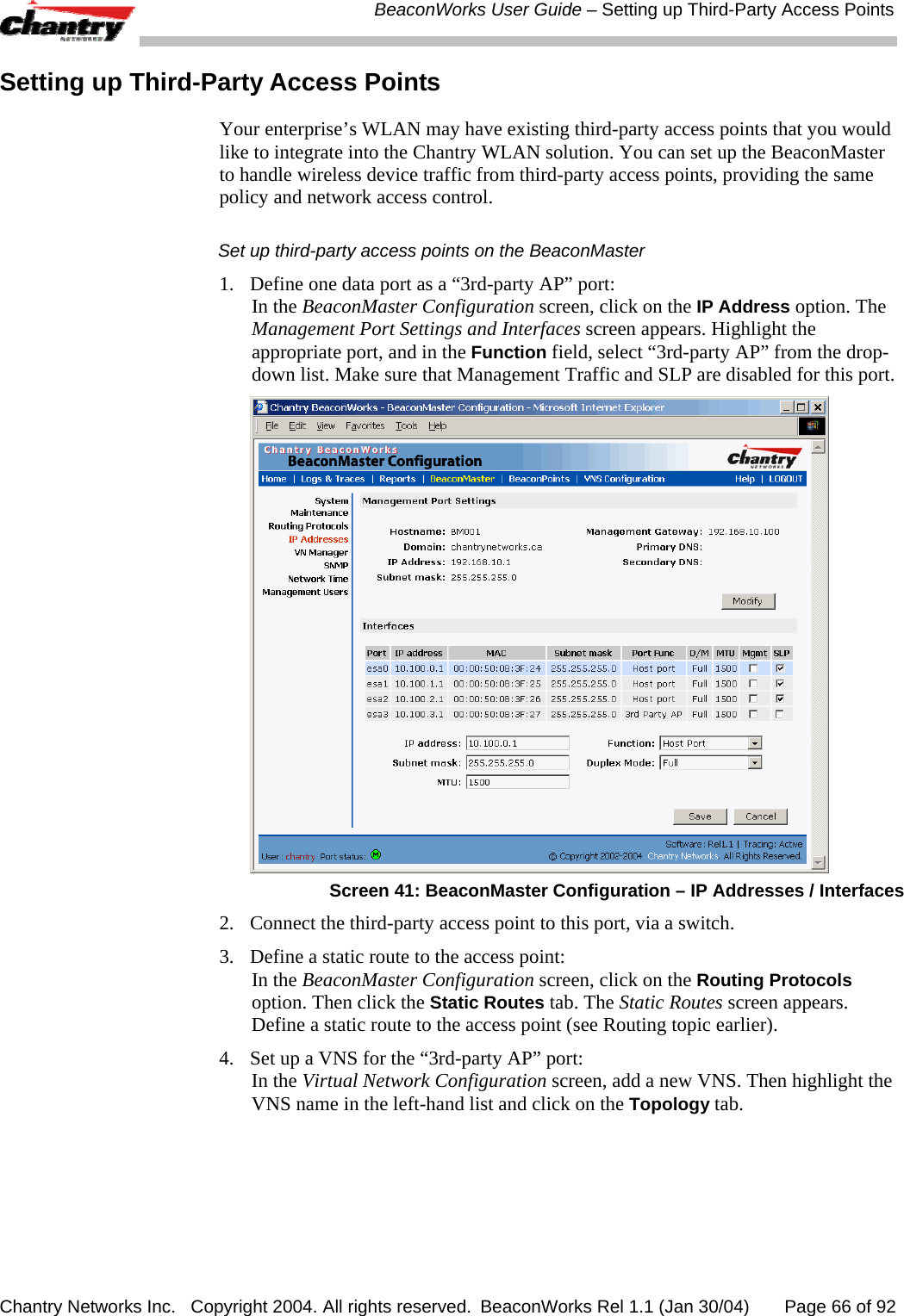
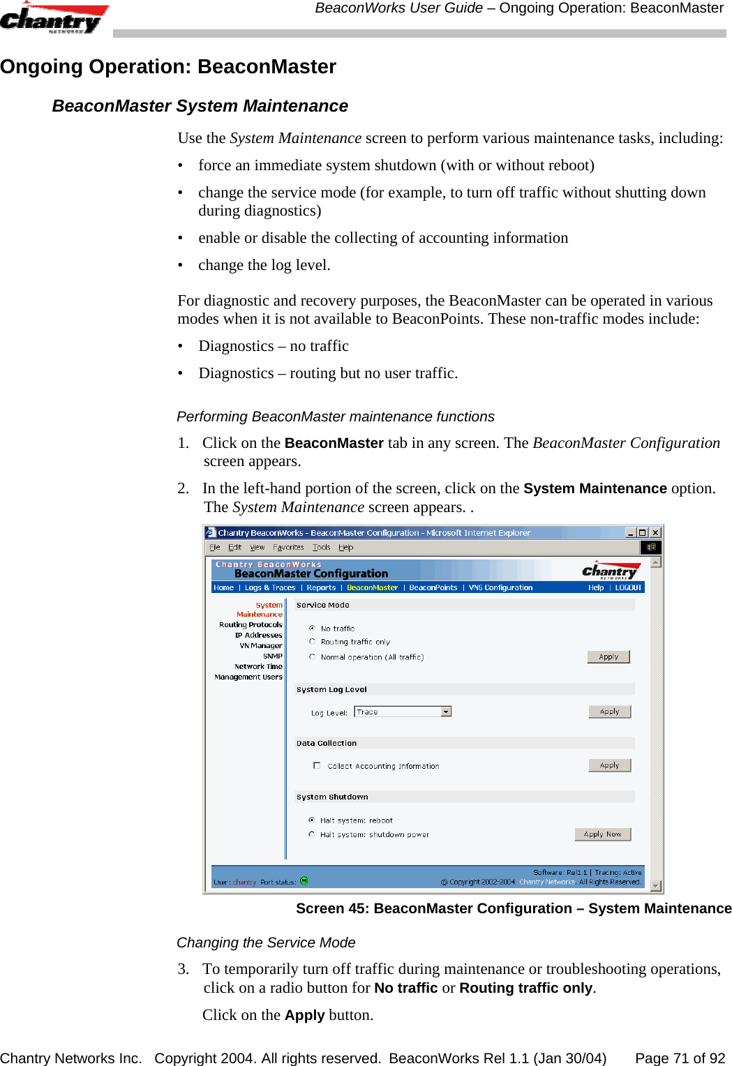
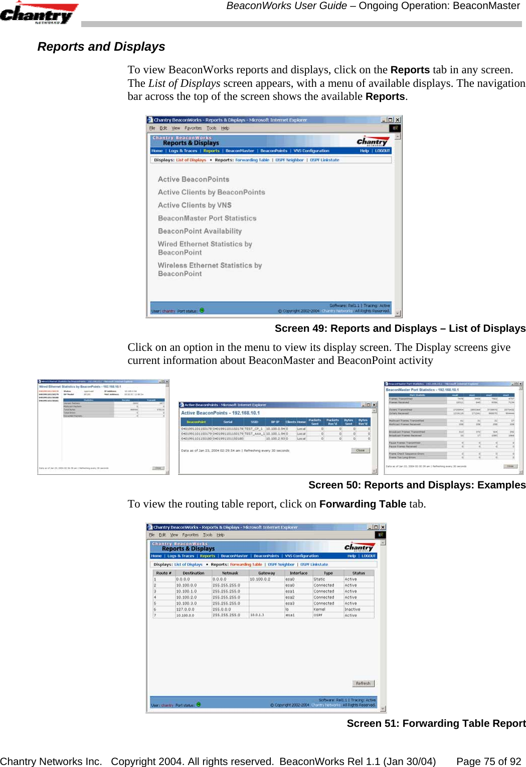
![BeaconWorks User Guide – BeaconWorks Configuration: Data Port and Routing Setup Chantry Networks Inc. Copyright 2004. All rights reserved. BeaconWorks Rel 1.1 (Jan 30/04) Page 23 of 92 Screen 9: BeaconMaster Configuration – Static Routes 3. To add a new route, click in the Destination Address field, and key in the destination IP address of a packet. [The destination network IP address that this static route applies to. Packets with this destination address will be sent to the Destination below.] To define a default static route for any unknown address not in the routing table, key in 0.0.0.0 4. Key in the Subnet Mask. For the IP address, the appropriate subnet mask to separate the network portion from the host portion of the address (typically 255.255.255.0) For the default static route for any unknown address, key in 0.0.0.0. 5. Select an outbound destination for the packets, either: Click on the radio button in the Gateway field, and key in the IP address of the gateway (the IP address of the specific router port or gateway, on the same subnet as the BeaconMaster, to which to route these packets; that is, the IP address of the next hop between the BeaconMaster and the packet’s ultimate destination) , or Click on the Interface button, and select a port from the pull-down list. 6. Click on the Add button. The new route appears in the list, numbered sequentially. 7. Click on Save to update the routing table on the BeaconMaster. Viewing the Routing Table on the BeaconMaster To view the static routes that have been defined for the BeaconMaster, click on the View Forwarding Table tab. This displays the Forwarding Table Screen from the Reports & Displays area of the user interface.](https://usermanual.wiki/Chantry-Networks/BP200E.users-manual/User-Guide-442395-Page-23.png)
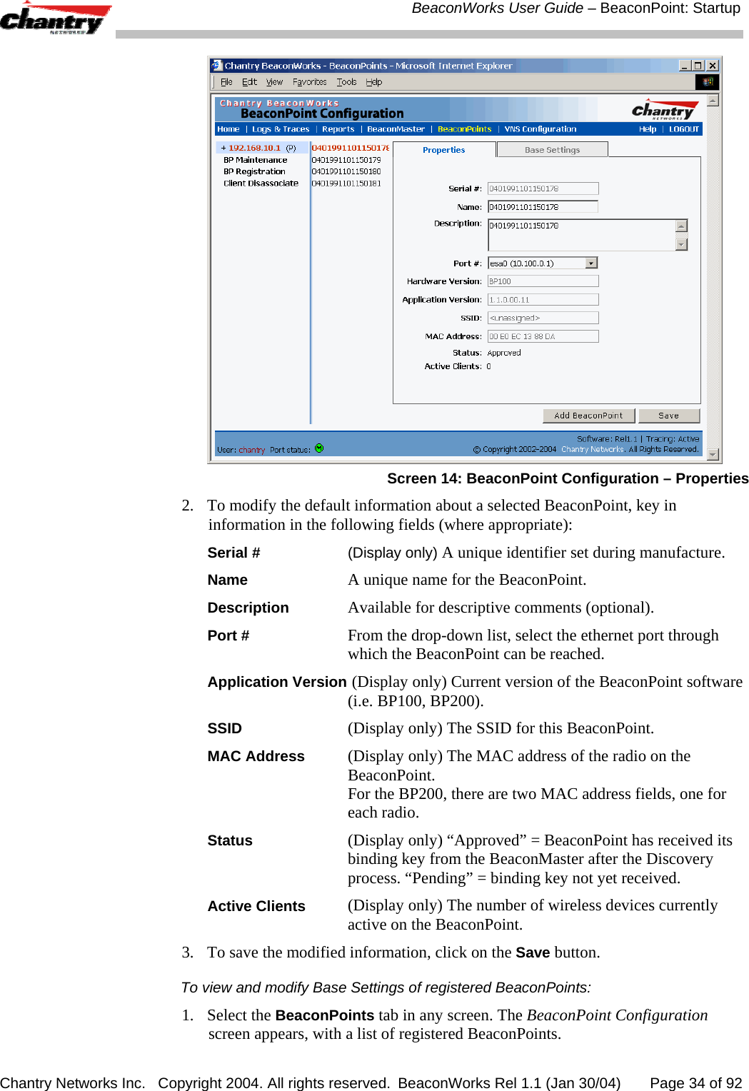
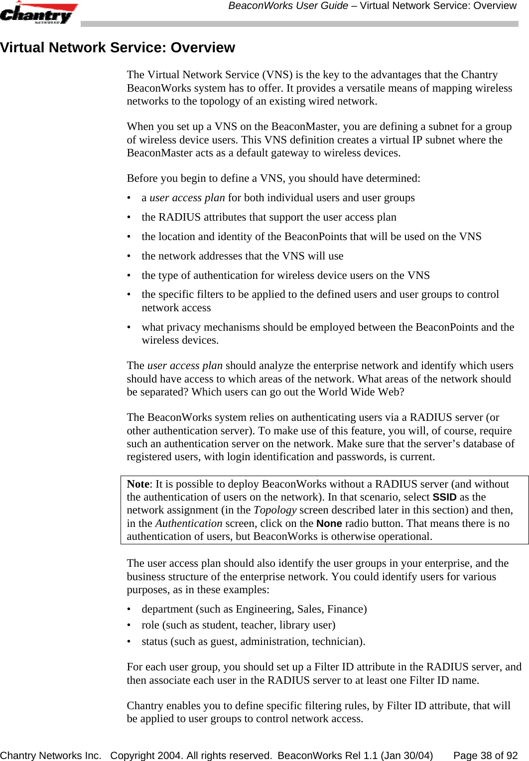
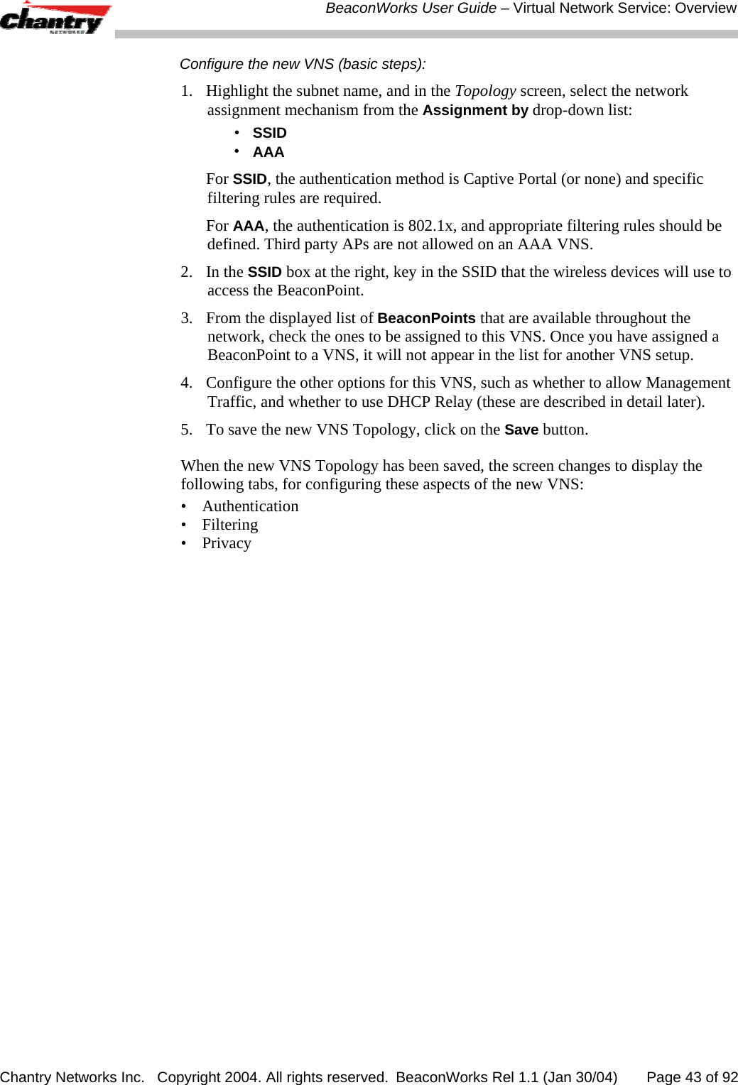
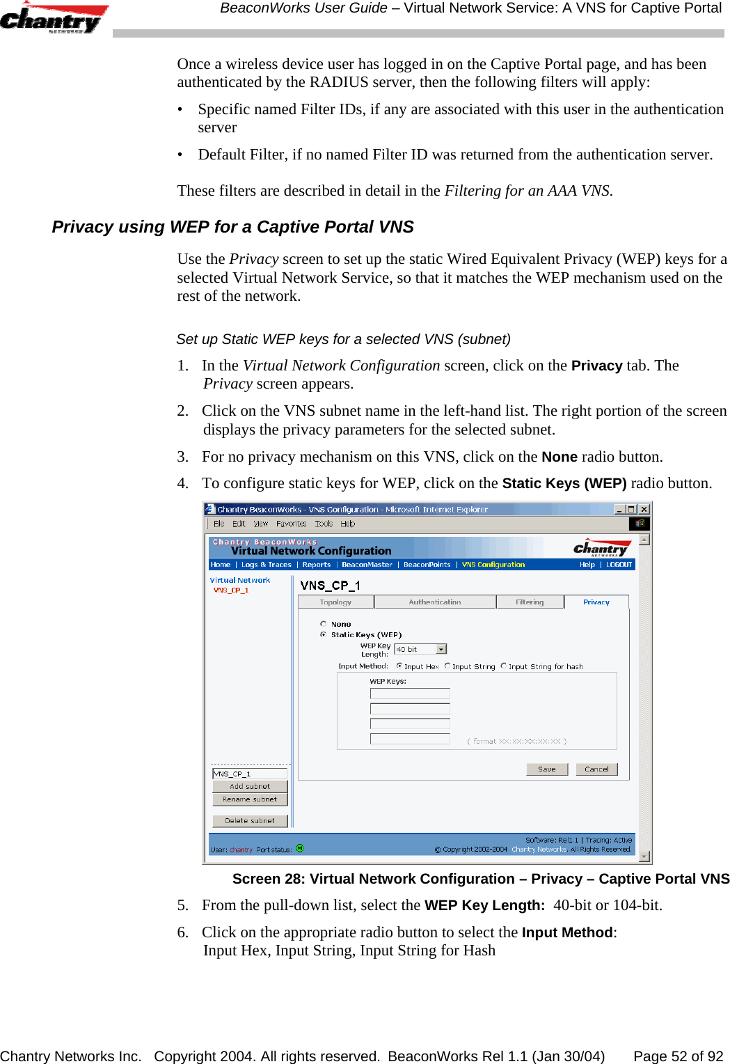
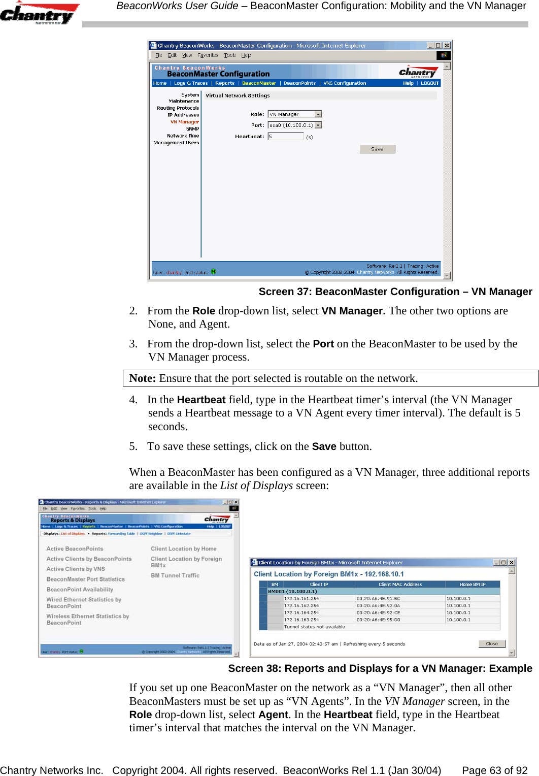
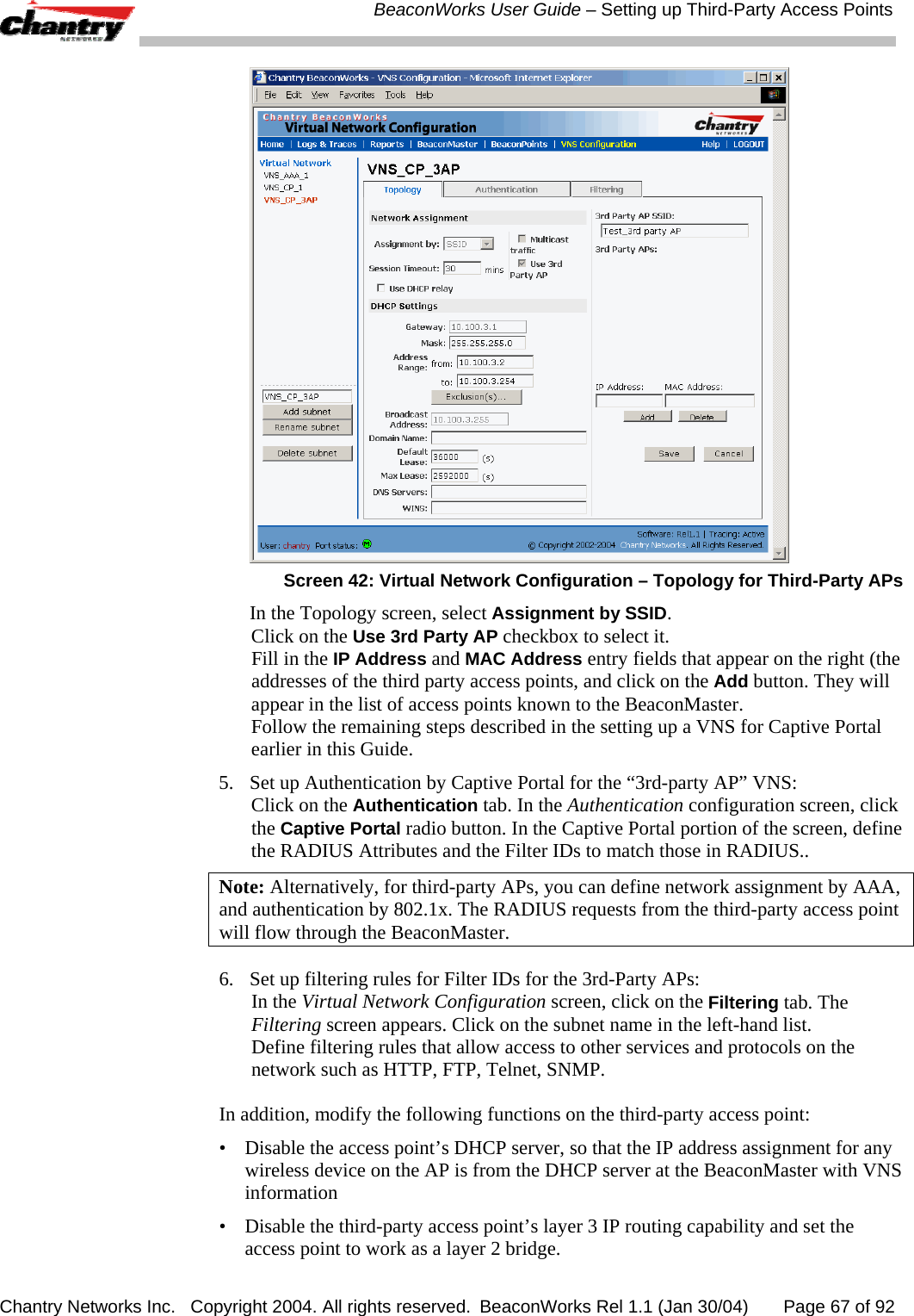
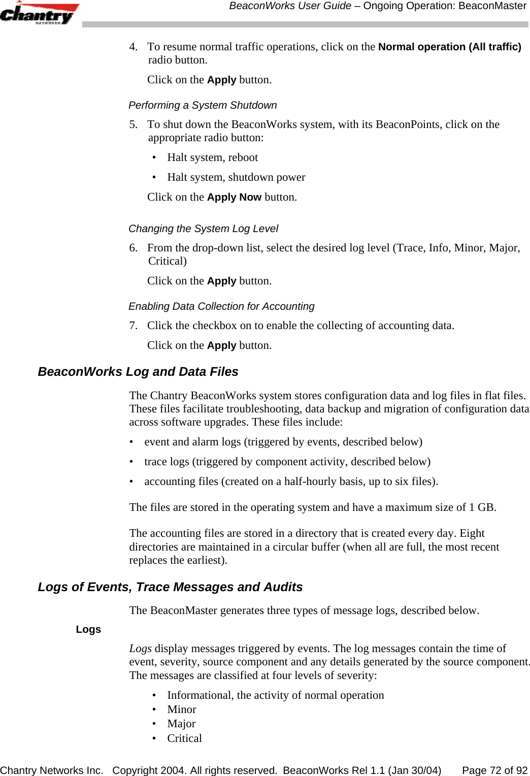
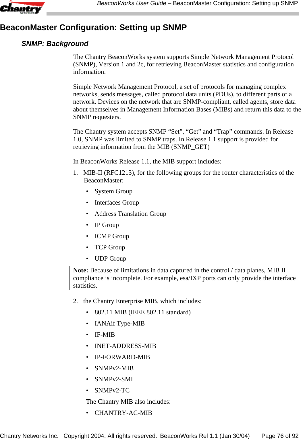
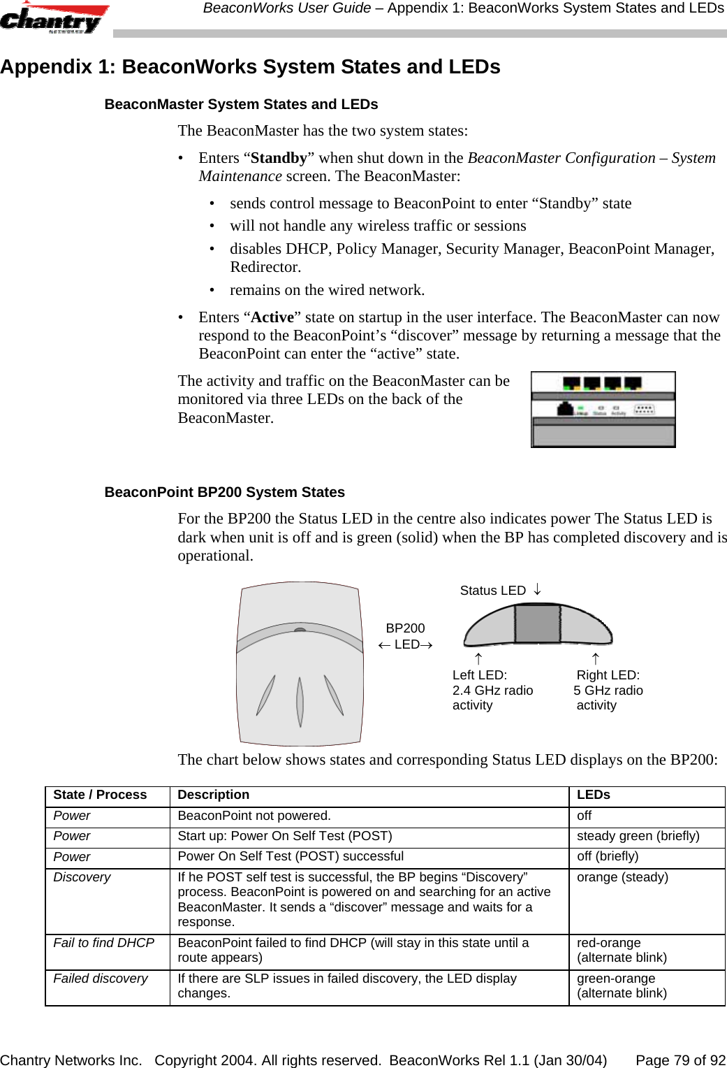
![BeaconWorks User Guide – BeaconPoint: Startup Chantry Networks Inc. Copyright 2004. All rights reserved. BeaconWorks Rel 1.1 (Jan 30/04) Page 32 of 92 DHCP (Dynamic Host Configuration Protocol), is the standard means of providing IP addresses dynamically to devices on a network. SLP (Service Location Protocol) is a means of allowing client applications to discover network services without knowing their location beforehand. Devices advertise their services, using a Service Agent. In larger installations, a Directory Agent collects information from Service Agents and creates a central repository. A device that is searching for a service makes use of the SLP User Agent to retrieve information from Service Agents or Directory Agents. DHCP Option 78 returns a list of IP addresses of Directory Agents. Meanwhile, the active BeaconMaster has management software that has registered itself as a service. When a BeaconMaster starts up, it queries the DHCP server for Option 78. It registers with the Directory Agents as service type “Chantry”. This information enables the BeaconPoint to discover the location of the BeaconMaster. Note: See the BeaconWorks Reference Guide for more information about DHCP and SLP. The BeaconPoint’s Discovery Process and LED Sequence As soon as the BeaconPoint is powered and connected to the LAN, it begins its automatic process to discover and register with the BeaconMaster. For the BP200 the Status LED in the centre also indicates power. The Status LED is dark when unit is off and is green (solid) when the BP has completed discovery and is operational. BP200 ← LED→ Status LED ↓ ↑ ↑ Left LED: Right LED: 2.4 GHz radio 5 GHz radio activity activity The boot sequence described below is the same for both versions of the BeaconPoint. However, the LED sequence described with it is for the BP200 only. 1. When powered on, the BeaconPoint status LED turns from dark to green briefly. Status LED: green (solid) then to dark before beginning boot sequence. 2. [available in Release 2.0 only] The BeaconPoint performs a self-test. [available in Release 2.0 only] Status LED: red (solid) if POST failed. 3. The “Discovery” mode: the BeaconPoint sends a request to the DHCP server on the enterprise network for the location of the BeaconMaster. (This is accomplished through a combination of Service Location Protocol (SLP) and DHCP, as described above.) Status LED: orange (solid) while searching (“Discovery”)](https://usermanual.wiki/Chantry-Networks/BP200E.users-manual/User-Guide-442395-Page-32.png)
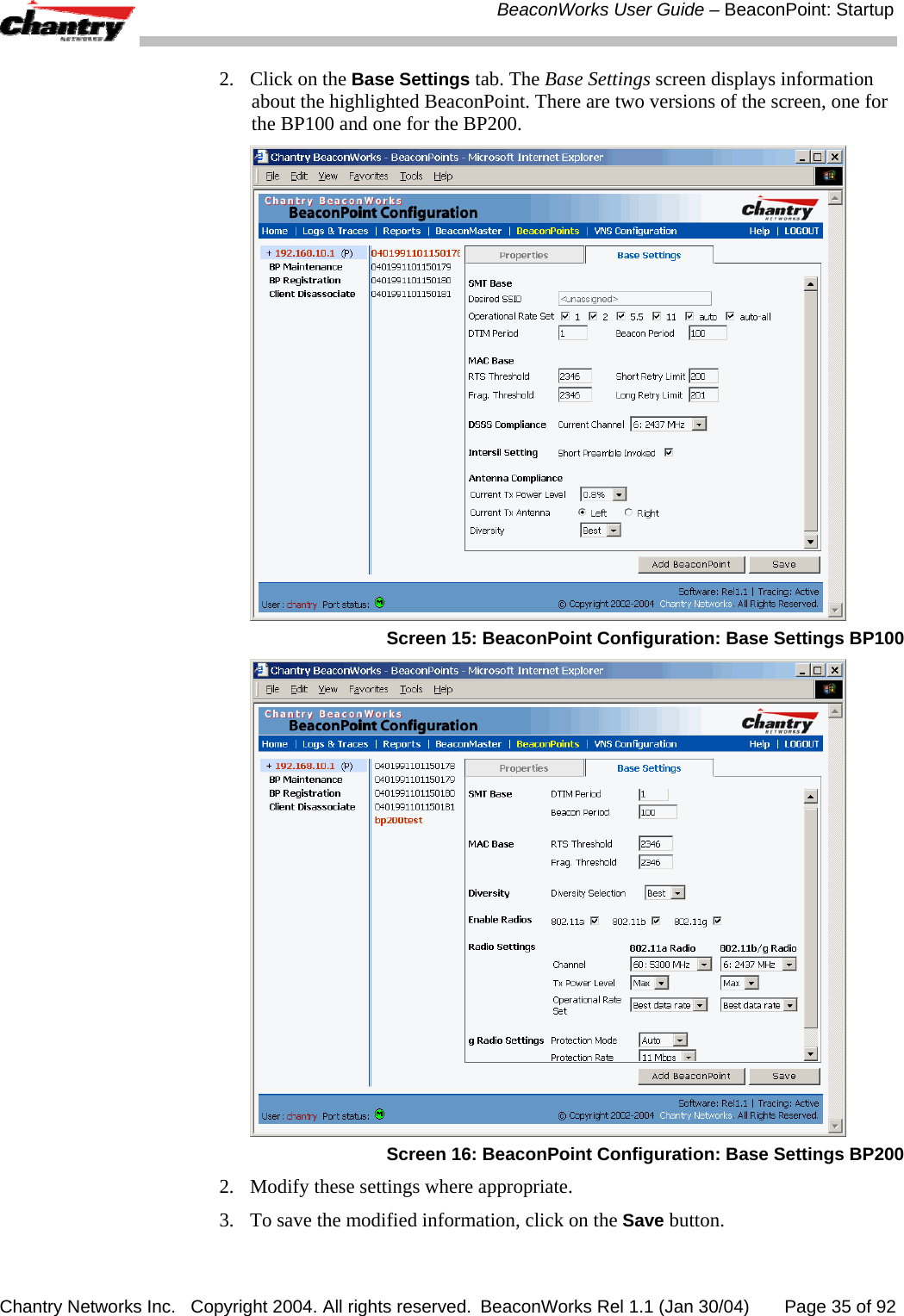
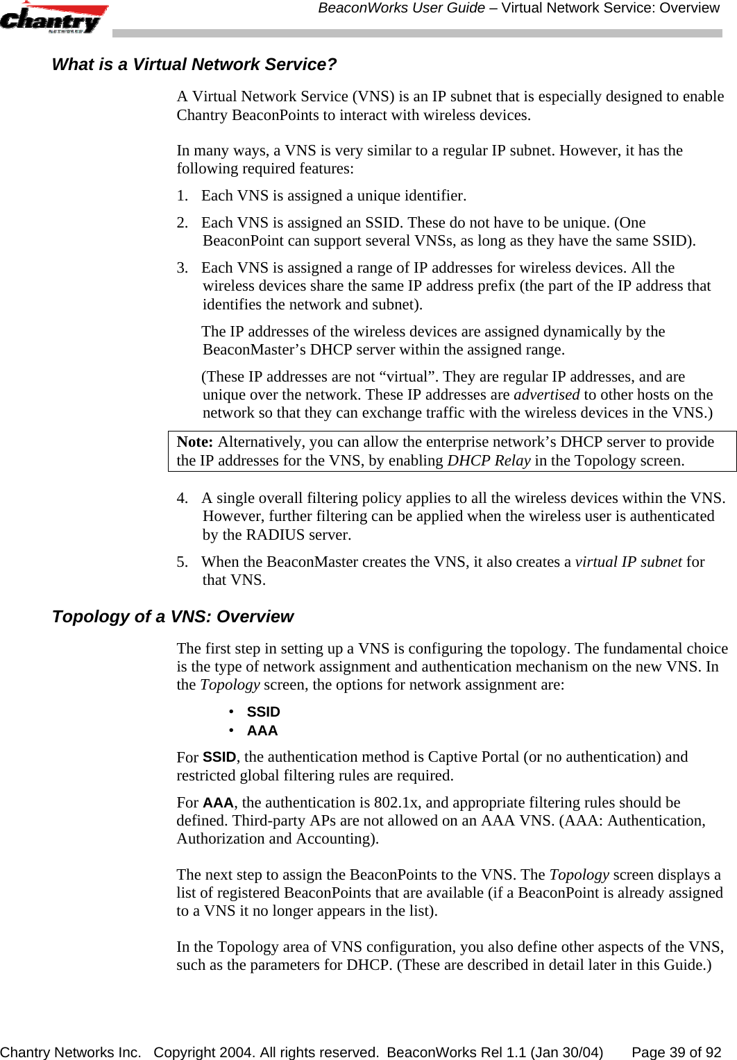

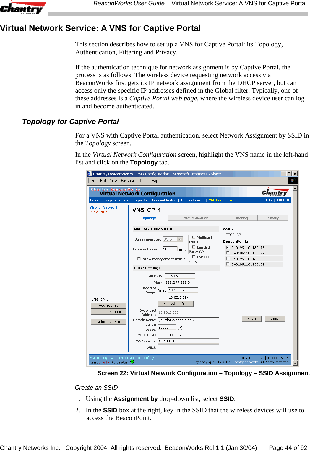
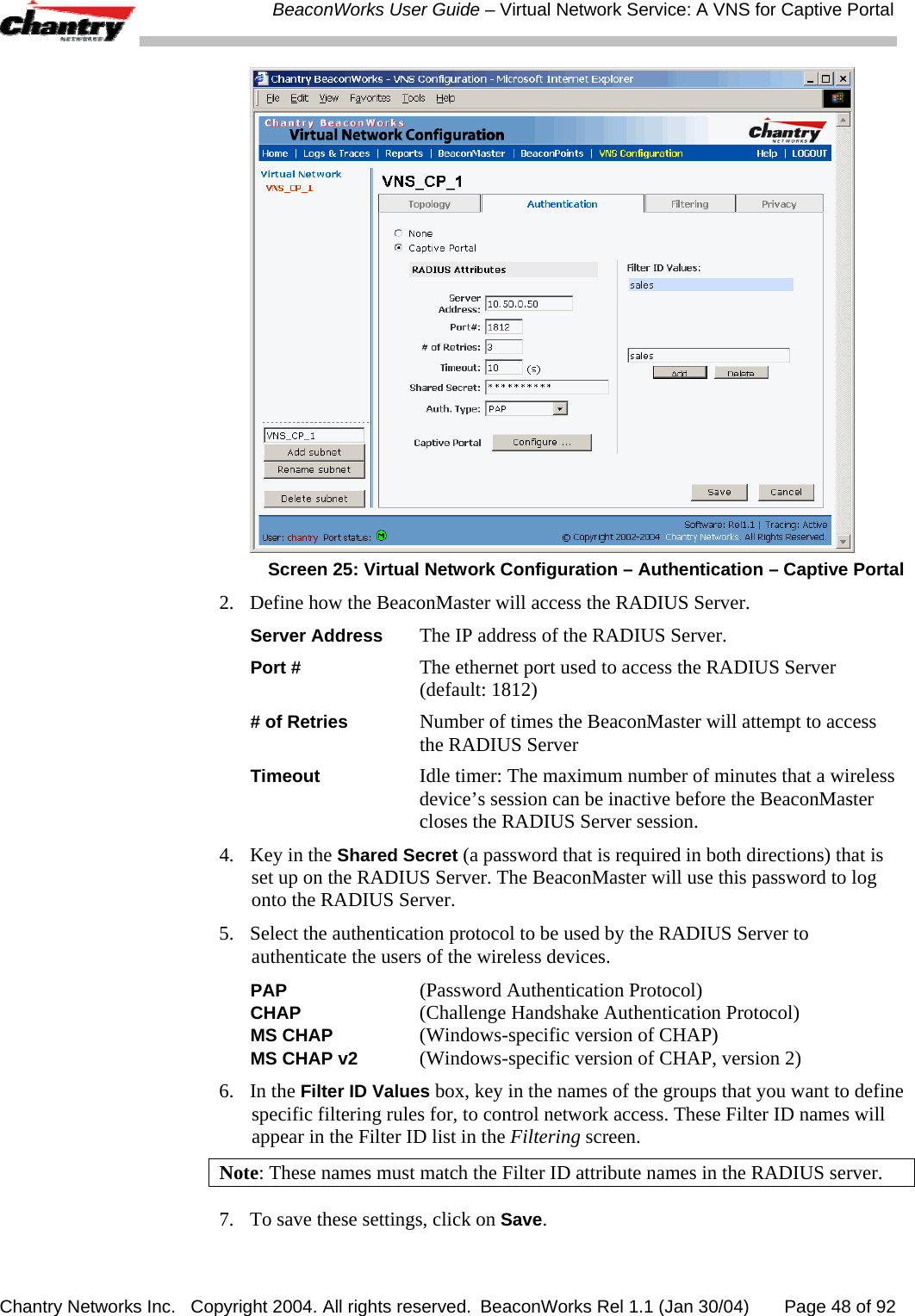
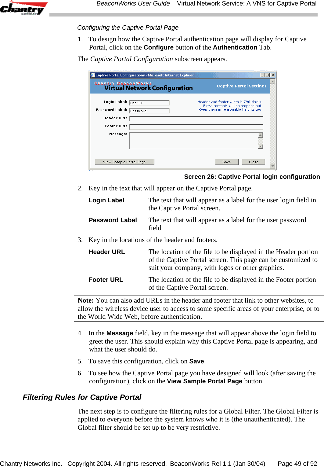
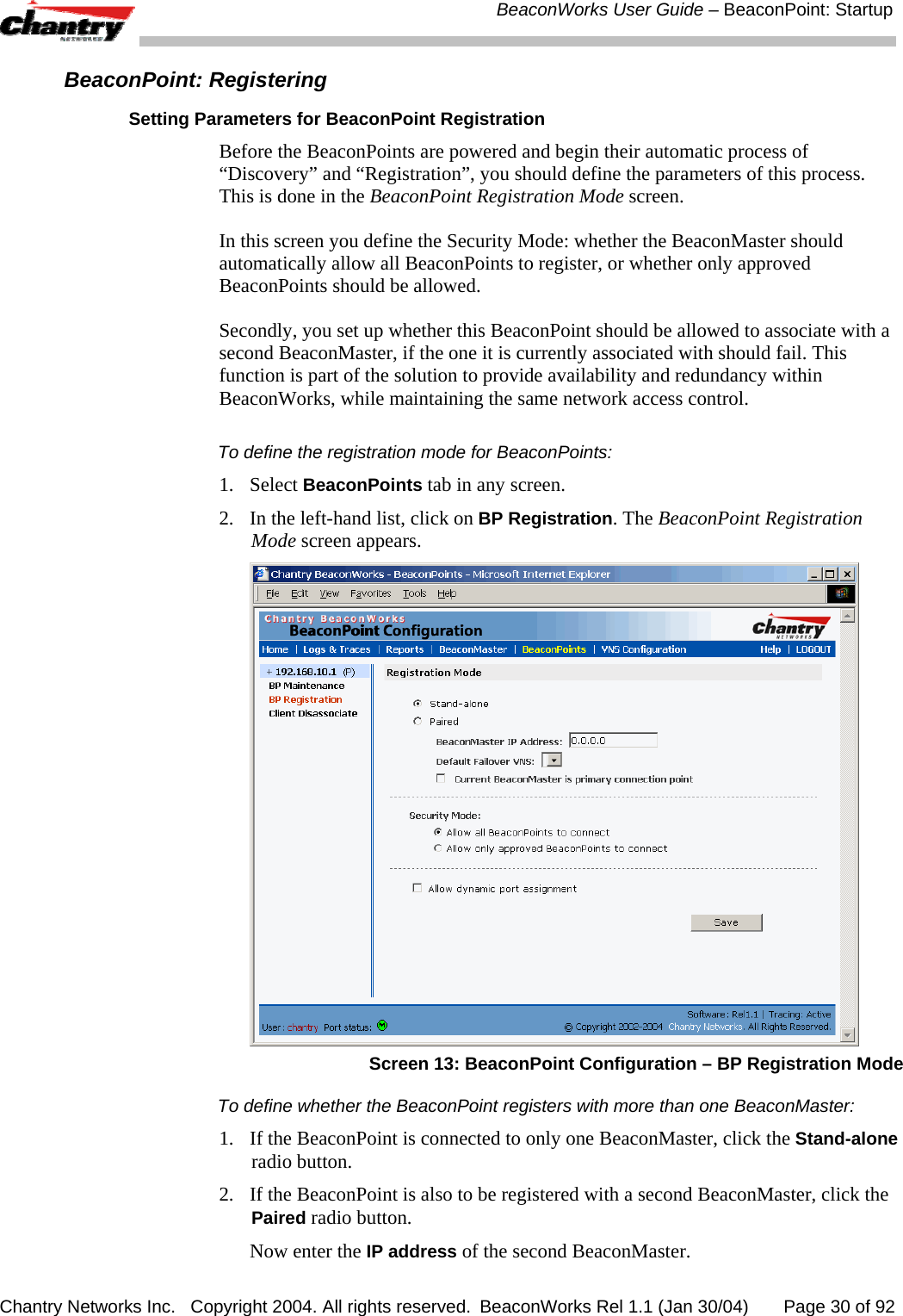
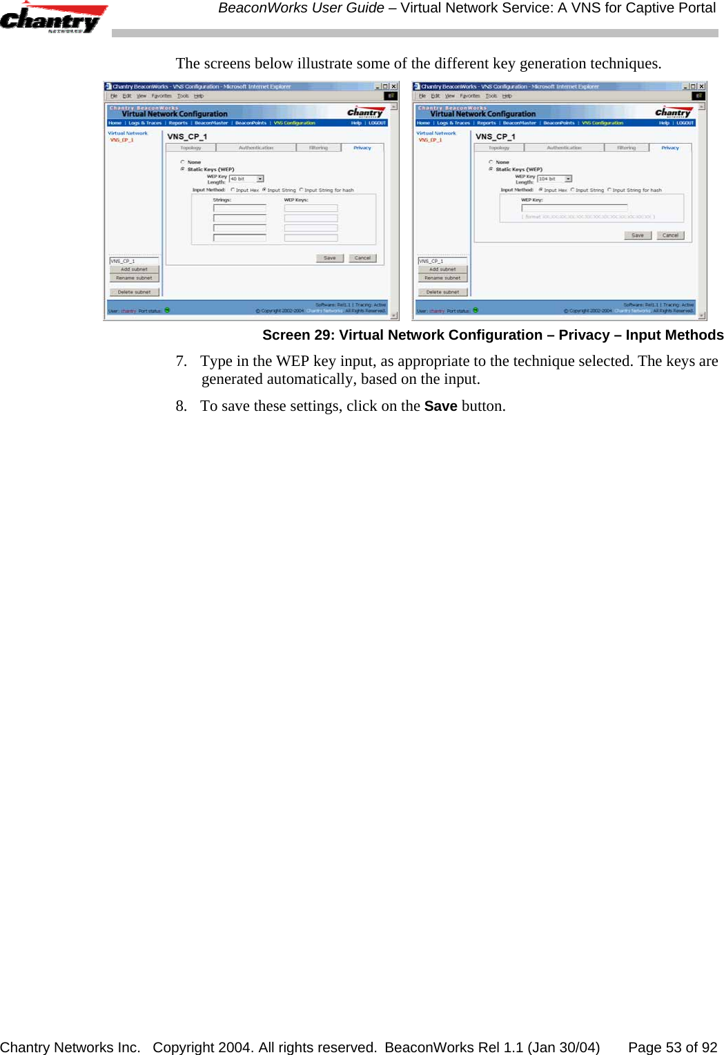
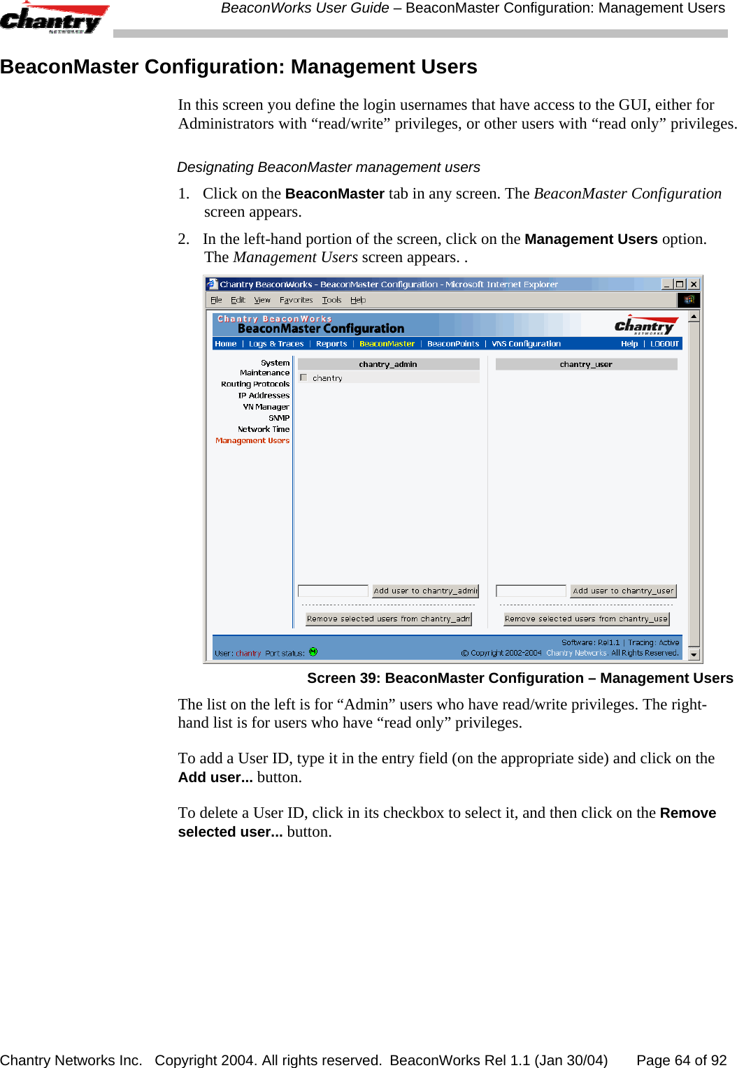
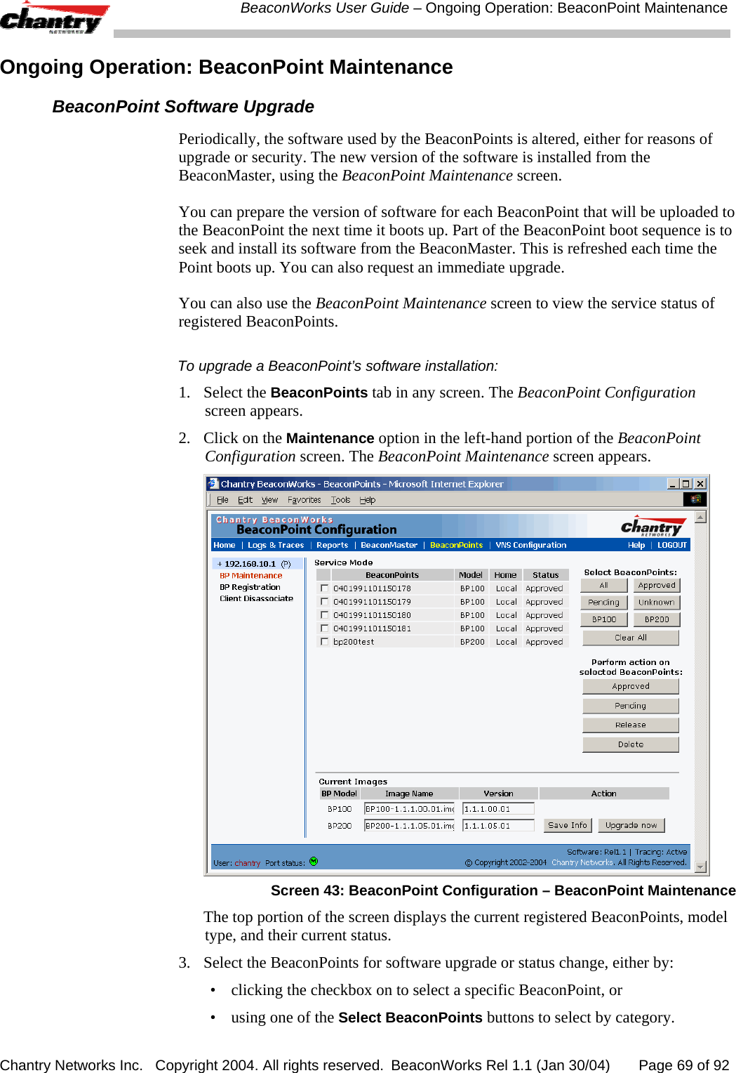
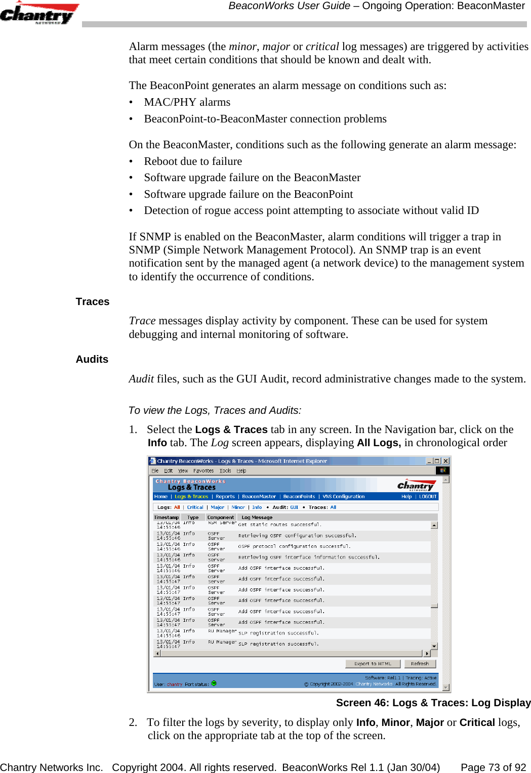
![BeaconWorks User Guide – Virtual Network Service: A VNS for Captive Portal Chantry Networks Inc. Copyright 2004. All rights reserved. BeaconWorks Rel 1.1 (Jan 30/04) Page 51 of 92 Protocol: Select from the drop-down list (may include UDP, TCP, IPsec-ESP, IPsec-AH, ICMP) Note: For Captive Portal, select IP / Port and key in the IP address you defined as the Network Address in the Topology screen for this VNS (its default gateway) 4. Click on the Add button. The information appears in a new line in the Filter Rules area of the screen. 5. Highlight the new filtering rule and fill in (or leave unchecked) the three checkboxes in the combinations that define the traffic access: In: Click checkbox on to refer to traffic from the wireless device that is trying to get on the network (“going to” to network) Out: Click checkbox on to refer to traffic from the network host that is trying to get to a wireless device. (“coming from” the network) Allow Click checkbox on to allow. Leave unchecked to disallow.. Note: For Captive Portal, to allow access to the IP address, check all three boxes on. 6. Edit the order of a filtering rule by highlighting the line and clicking on the Up and Down button. The filtering rules are executed in the order created here 7. To save the filtering rules, click on the Save button. Global Filters: Examples The basic Global filter for Captive Portal has three rules in the following order: In Out Allow IP / Port Description x x x IP address of the Default Gateway Allow all incoming wireless devices access to the default gateway of the VNS. x x x IP address of the DNS Server Allow all incoming wireless devices access to the DNS server of the VNS. x x *.*.*.* Deny everything else. Note: If you put URLs in the header and footer of the Captive Portal page, you must include a filtering rule to allow traffic to each of these URLs. Put this rule above the “deny everything” rule. Here is another example of a Global filter that adds two more filtering rules: one denies access to a specific IP address, and the next rule allows only HTML traffic, before denying all other access: In Out Allow IP / Port Description x x x IP address of the Default Gateway Allow all incoming wireless devices access to the default gateway of the VNS. x x x IP address of the DNS Server Allow all incoming wireless devices access to the DNS server of the VNS. x x [a specific IP address] Deny all traffic to a specific IP address. x x x *.*.*.*:80 Allow all port 80 (HTML) traffic. x x *.*.*.*. Deny everything else.](https://usermanual.wiki/Chantry-Networks/BP200E.users-manual/User-Guide-442395-Page-51.png)
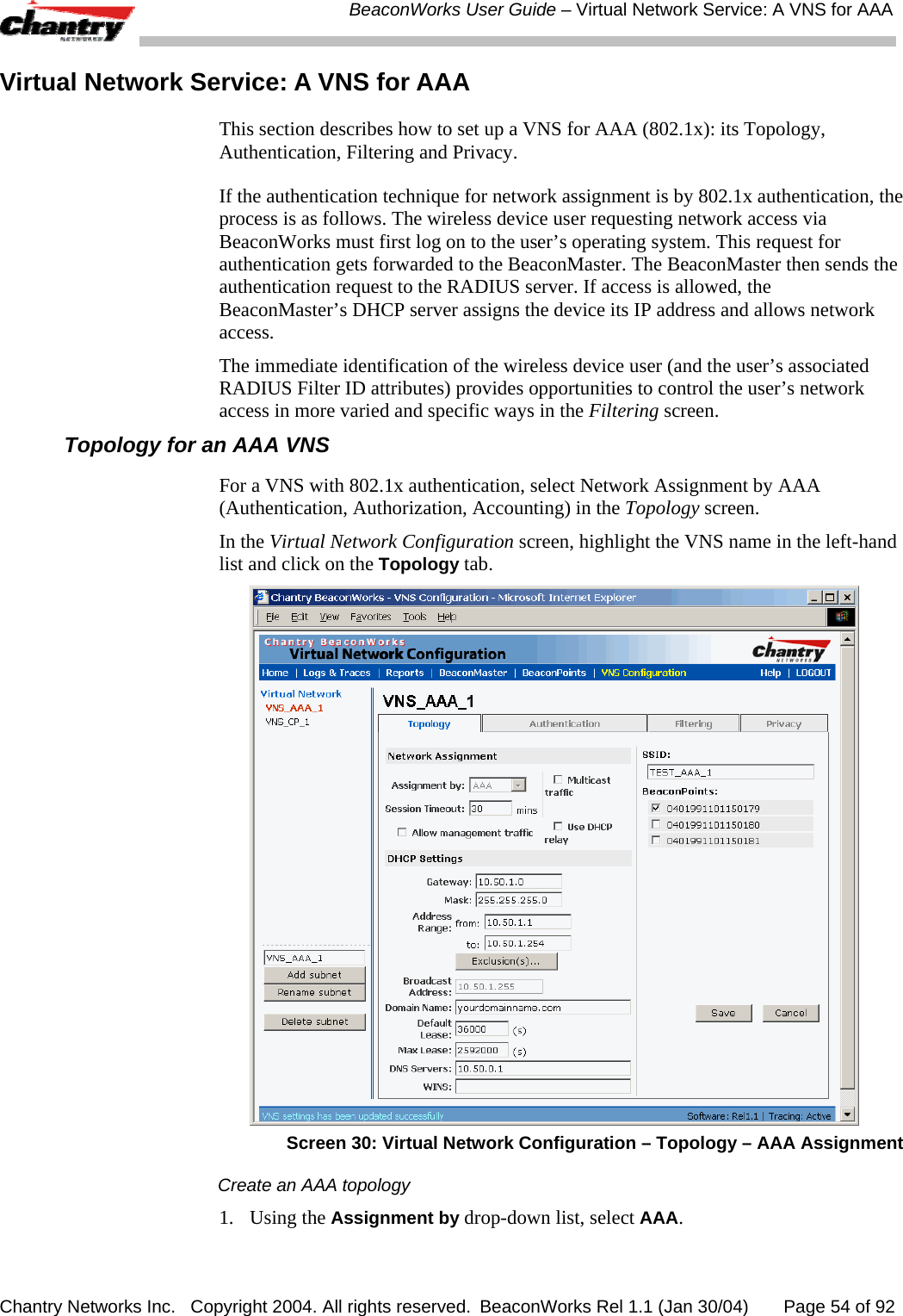
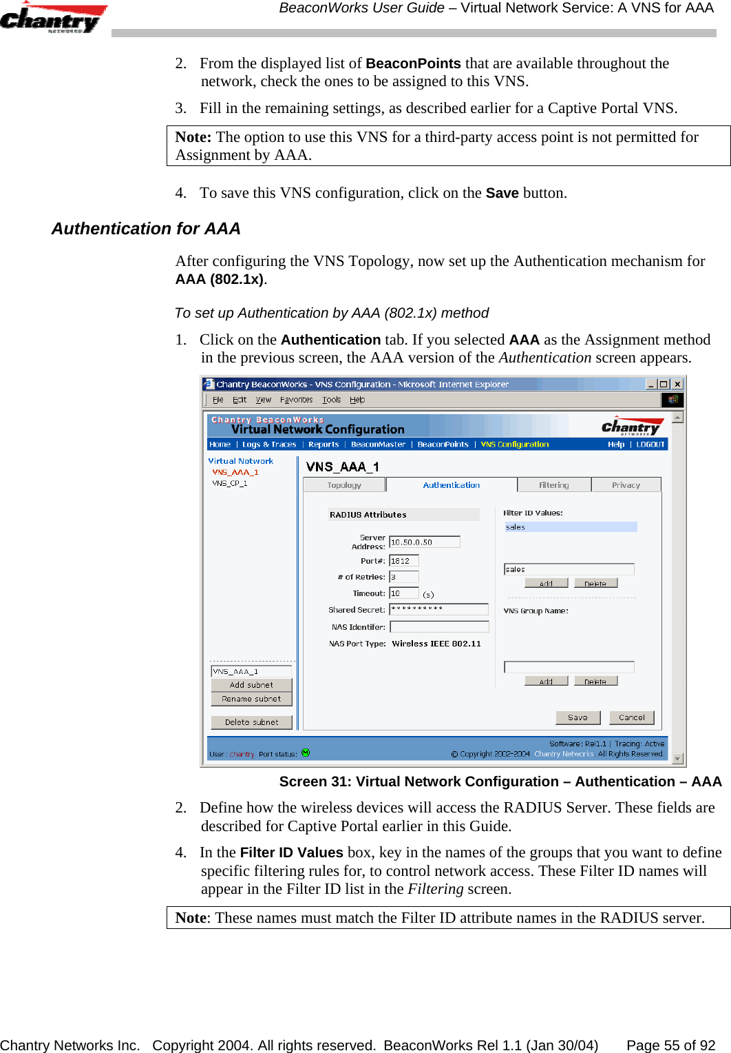
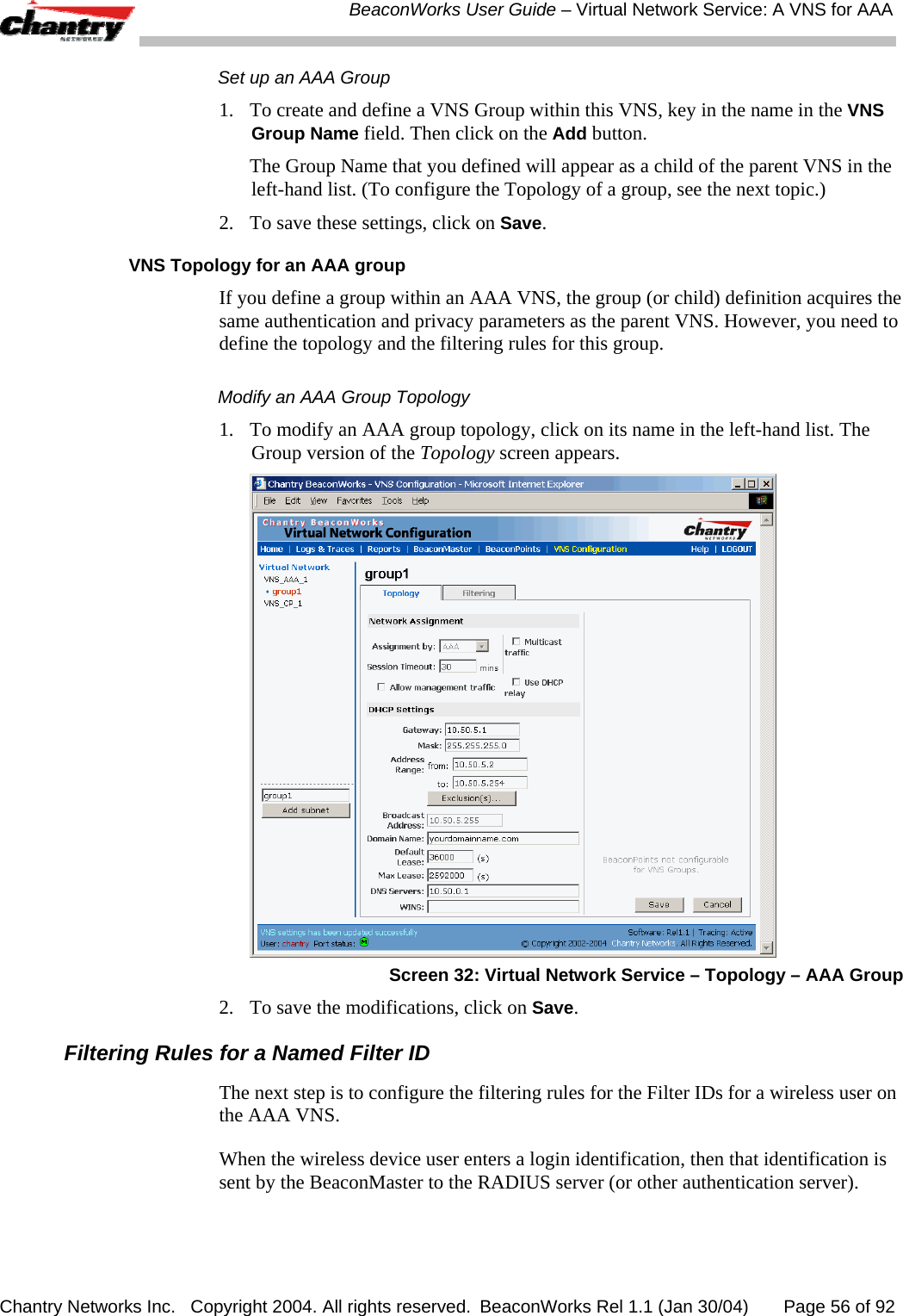
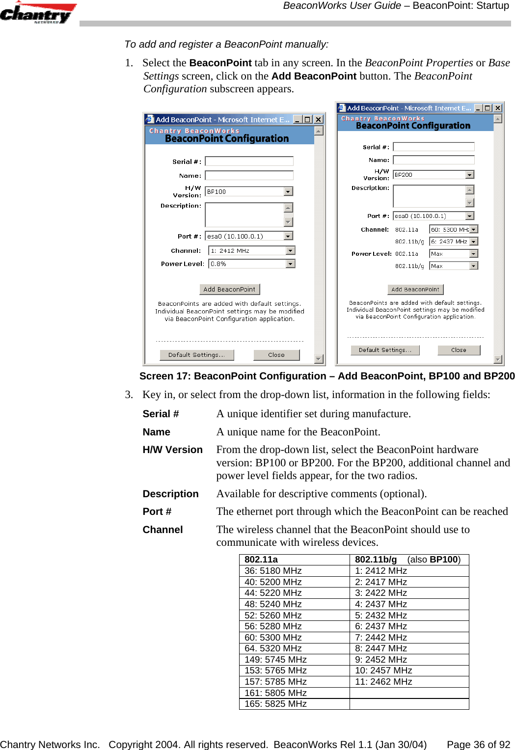
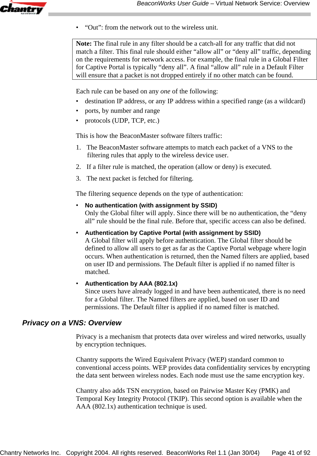
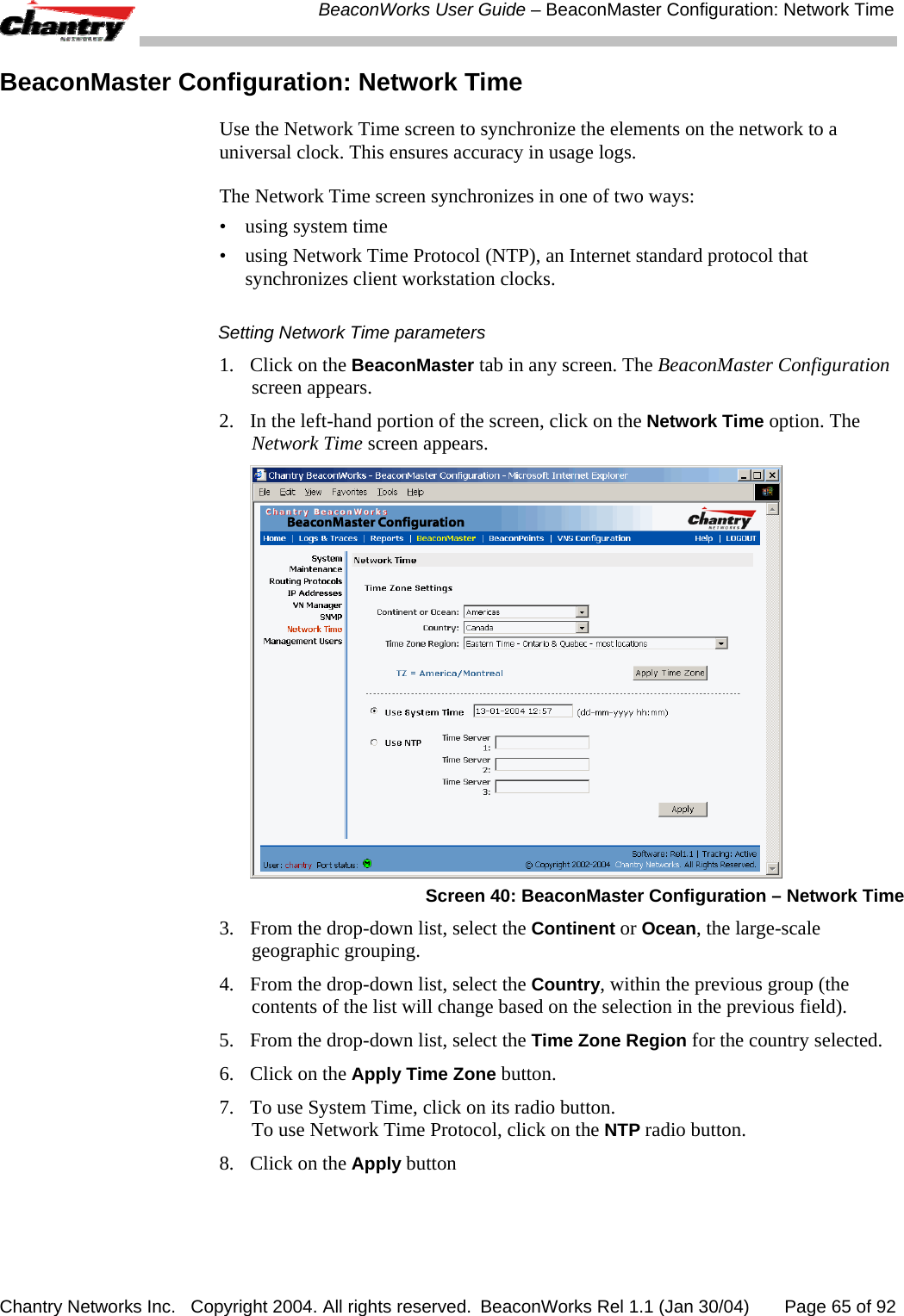
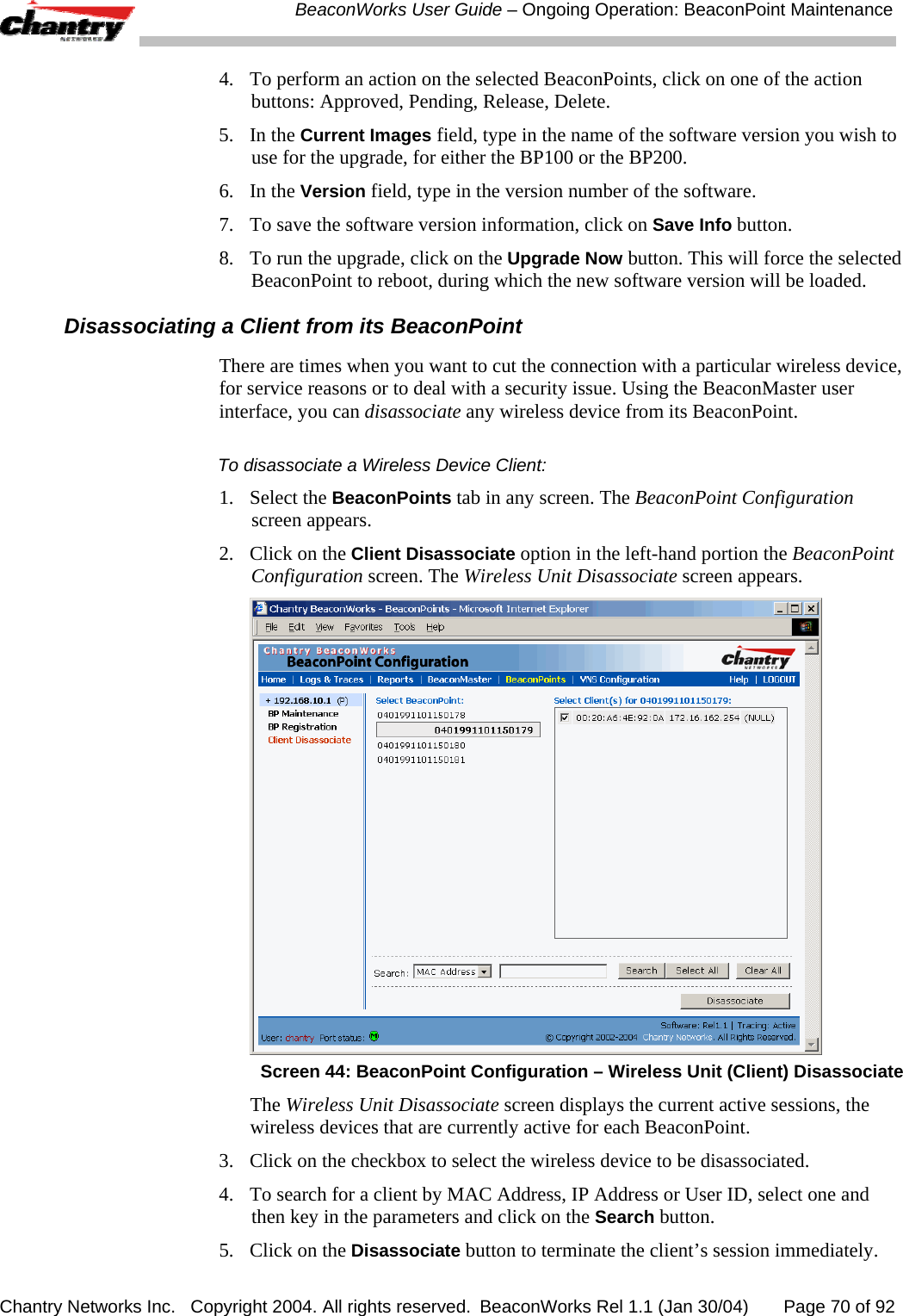
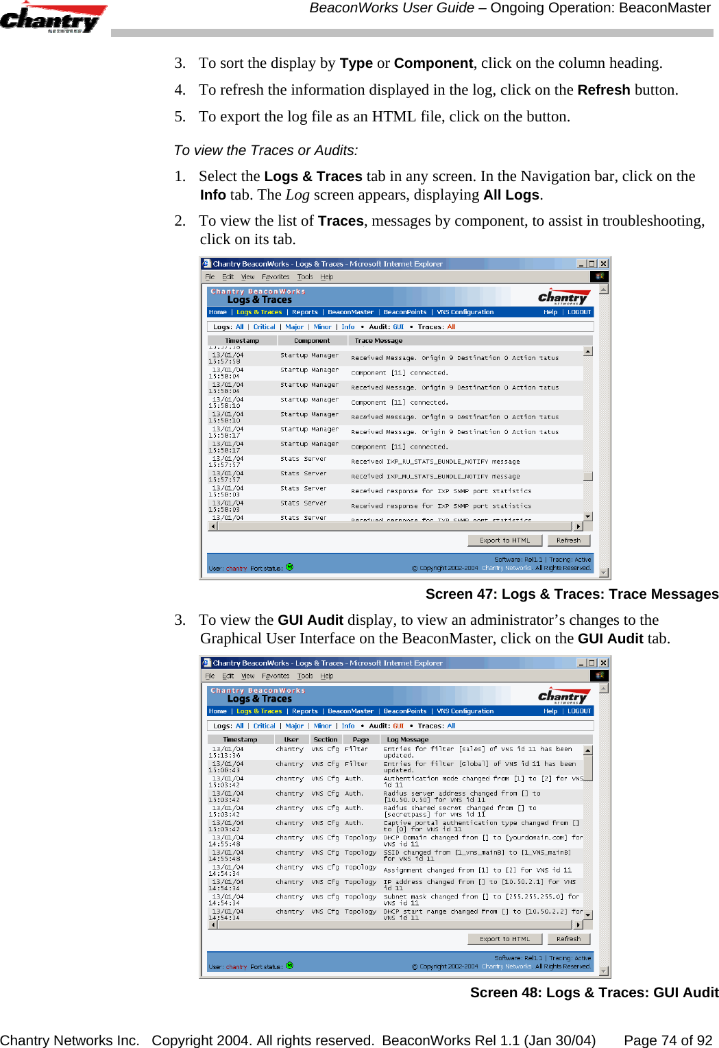
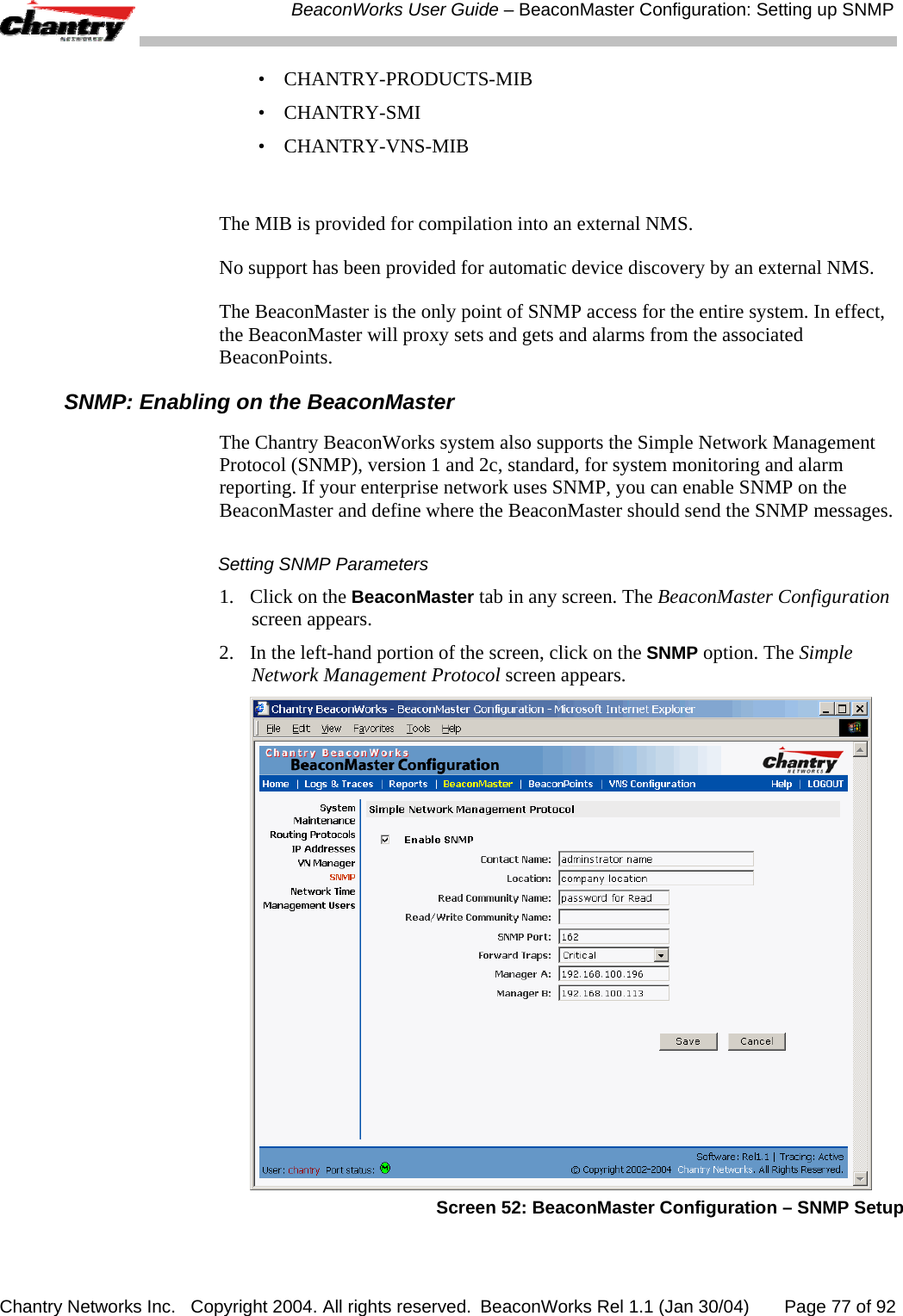
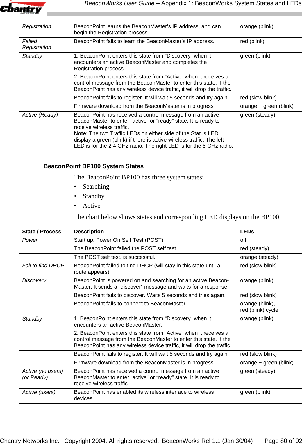
![BeaconWorks User Guide – Virtual Network Service: A VNS for AAA Chantry Networks Inc. Copyright 2004. All rights reserved. BeaconWorks Rel 1.1 (Jan 30/04) Page 57 of 92 When the server allows this request for authentication, the server may also send back to the BeaconMaster other identifiers associated with this user. This could be any Filter ID attributes defined in RADIUS. The BeaconMaster can now apply the specific filtering rules by Filter ID name for this wireless device user. These rules can define specific areas of the network that only users with the appropriate Filter ID can access. Note: The BeaconMaster’s Filter ID names must match the Filter ID attribute names in the RADIUS server. If no Filter ID is returned by the authentication server, then the Default Filter and its filtering rules will apply to the wireless device user. Note: These named Filter IDs (or the Default Filter) will also apply after a Captive Portal login has been authenticated. Define filtering rules for a named Filter ID: 1. In the Virtual Network Configuration screen, click on the Filtering tab. The Filtering screen appears. Click on the subnet name in the left-hand list. The right portion of the screen displays the filtering screen for the selected subnet. 2. Using the Filter ID drop-down list, select one of the names you defined in the Filter ID Values field in the Authentication screen [one of your enterprise’s user groups, such as Sales, Engineering, Teacher, Guest....] Screen 33: Virtual Network Configuration – Named Filter ID The screen automatically provides a “Deny All” rule already in place. This can be modified to “Allow All”, if appropriate to the network access needs for this VNS. 3. Select one of the following as the basis for each filtering rule you are defining: IP / Port: Click the radio button to select. Then type in the destination IP address, and if desired, the port designation on that IP address.](https://usermanual.wiki/Chantry-Networks/BP200E.users-manual/User-Guide-442395-Page-57.png)
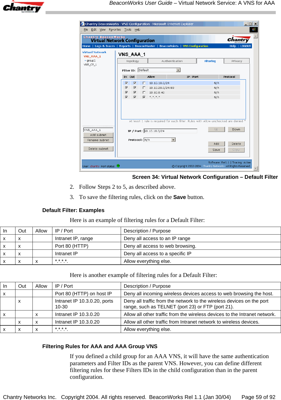
![BeaconWorks User Guide – Virtual Network Service: A VNS for AAA Chantry Networks Inc. Copyright 2004. All rights reserved. BeaconWorks Rel 1.1 (Jan 30/04) Page 58 of 92 Protocol: Select from the drop-down list (may include UDP, TCP, IPsec-ESP, IPsec-AH, ICMP) 4. Click on the Add button. The information appears in a new line in the Filter Rules area of the screen. 5. Highlight the new filtering rule and fill in (or leave unchecked) the three checkboxes in the combinations that define the traffic access: In: Click checkbox on to refer to traffic from the wireless device that is trying to get on the network (“going to” to network) Out: Click checkbox on to refer to traffic from the network host that is trying to get to a wireless device. (“coming from” the network) Allow Click checkbox on to allow. Leave unchecked to disallow.. 6. Edit the order of a filtering rule by highlighting the line and clicking on the Up and Down button. The filtering rules are executed in the order created here 7. To save the filtering rules, click on the Save button. Named Filters by Filter ID: Examples Below are two examples of possible filtering rules for a named Filter ID. The first disallows only some specific access before allowing everything else. In Out Allow IP / Port Description x x *.*.*.*:22-23 Deny all telnet sessions x x [specific IP address, range] Deny all traffic to a specific IP address, or address range x x x *.*.*.*. Allow everything else. The second example does the opposite of the first example. It allows only some specific access and denies everything else. In Out Allow IP / Port Description x x x [specific IP address, range] Allow all traffic to a specific IP address, or address range x x *.*.*.*. Deny everything else. Setting up Default Filtering Rules If, after authentication of the wireless device user, there is no named Filter ID returned by the authentication server for this user, then the Default Filter will apply. Define the filtering rules for a Default Filter 1. In the Virtual Network Configuration – Filtering screen, using the Filter ID drop-down list, select Default.](https://usermanual.wiki/Chantry-Networks/BP200E.users-manual/User-Guide-442395-Page-58.png)
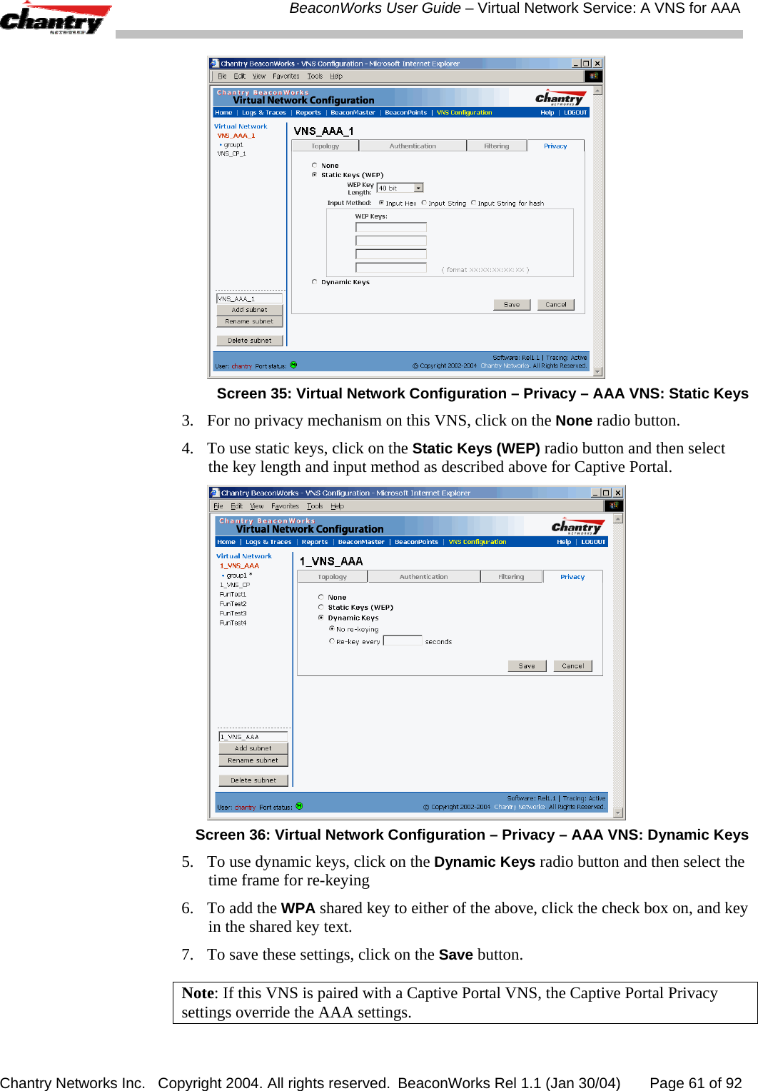
![BeaconWorks User Guide – Virtual Network Service: A VNS for AAA Chantry Networks Inc. Copyright 2004. All rights reserved. BeaconWorks Rel 1.1 (Jan 30/04) Page 60 of 92 Filtering Rules: Special Circumstances Filtering Rules to control communication between two wireless devices Traffic from two wireless devices on the same VNS and connected to the same BeaconPoint passes through the BeaconMaster, and is subject to filtering policy. You can set up filtering rules that allow each wireless device access to the default gateway, but prevent each device from communicating each other. Add the following two rules to a Filter ID before allowing everything else: In Out Allow IP / Port Description / Purpose x x x [Intranet IP] Allow access to the Gateway IP address of the VNS only x x [Intranet IP, range] Deny all access to the VNS subnet range 0/24 x x x *.*.*.*. Allow everything else. Filtering Rules to control access to services on the BeaconMaster For each type of port function set up for the BeaconMaster’s data ports, filtering rules control access to management services on that port. These filtering rules were implicitly created in two ways: • at the port level, when you set the “Allow Management” flag on for a port, in the data port setup on the BeaconMaster. • at the VNS level, when you clicked the checkbox on for “Allow Management Traffic” when setting up a VNS Topology. For example: • For Router and Host interfaces, you may allow access to management application (SSH, HTTPS, SNMP) and to BP registration mechanisms • For 3rd Party AP and VNS interfaces, you may wish to deny access to management or BP registration mechanisms, but allow access to captive portal (HTTP, HTTPS) and IP assignment infrastructure (DHCP). Only traffic with Filter IDs explicitly allowed by the interface’s filter are allowed to reach the BeaconMaster itself. All other traffic is dropped. Privacy using WEP for an AAA VNS Use the Privacy screen to set up 802.1x privacy mechanisms for an AAA Virtual Network Service. One of these mechanisms is privacy by Temporal Key Integrity Protocol ( TKIP), also known as Wi-Fi Protected Access (WPA) version 1. Set up privacy for a selected AAA VNS (subnet) 1. In the Virtual Network Configuration screen, click on the Privacy tab. The Privacy screen appears. Click on the VNS subnet name in the left-hand list. For an AAA VNS, the screen displays the appropriate privacy parameters.](https://usermanual.wiki/Chantry-Networks/BP200E.users-manual/User-Guide-442395-Page-60.png)

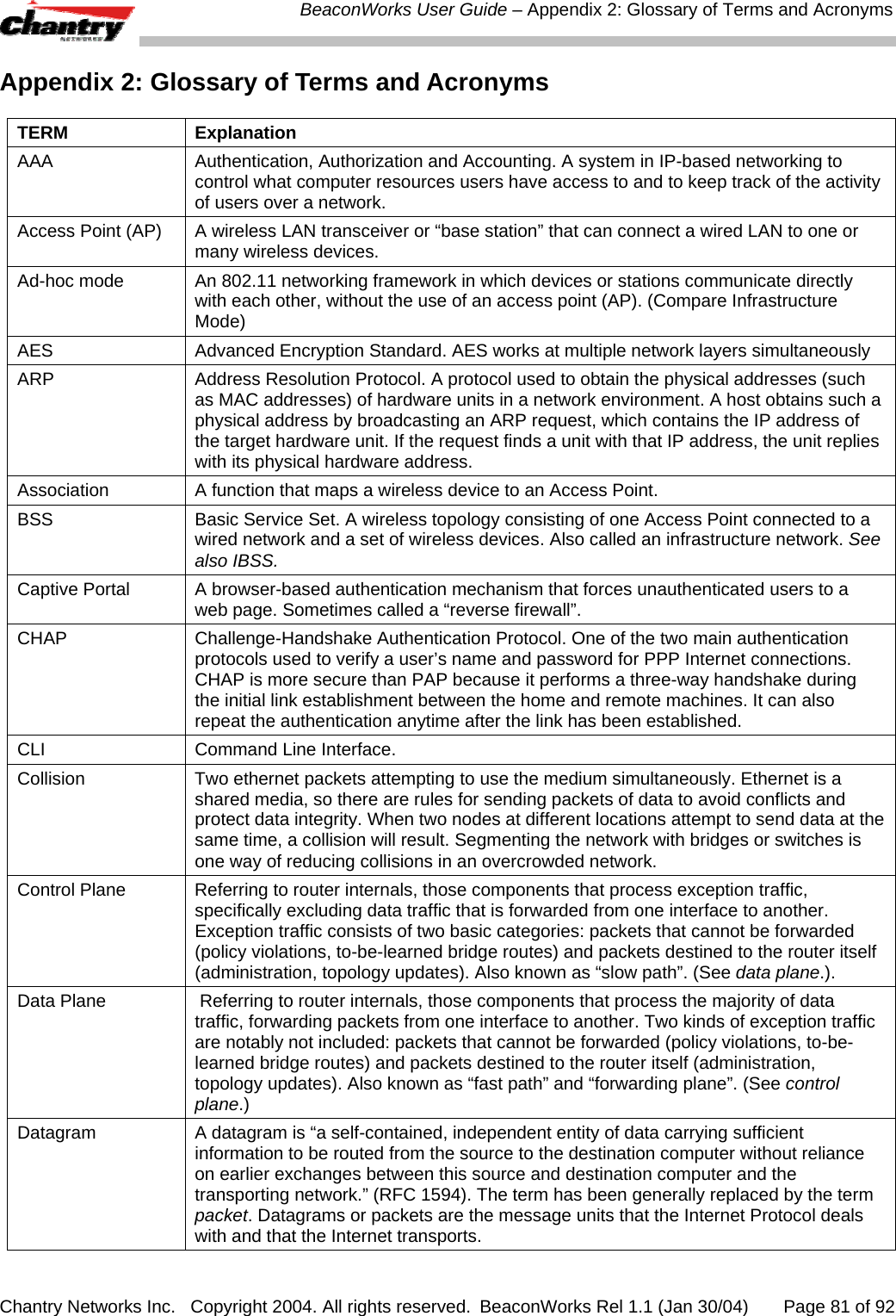
![BeaconWorks User Guide – Appendix 2: Glossary of Terms and Acronyms Chantry Networks Inc. Copyright 2004. All rights reserved. BeaconWorks Rel 1.1 (Jan 30/04) Page 82 of 92 TERM Explanation Decapsulation See tunnelling. Device Server A specialized, network-based hardware device designed to perform a single or specialized set of server functions. Print servers, terminal servers, remote access servers and network time servers are examples of device servers. DHCP Dynamic Host Configuration Protocol. A protocol for assigning dynamic IP addresses to devices on a network. With dynamic addressing, a device can have a different IP address every time it connects to the network. In some systems, the device’s IP address can even change while it is still connected. DHCP also supports a mix of static and dynamic IP addresses. DHCP consists of two components: a protocol for delivering host-specific configuration parameters from a DHCP server to a host and a mechanism for allocation of network addresses to hosts. (Compliant with IETF RFC1531.) Directory Agent (DA) Optional SLP agent that stores and maintains a cache of service advertisements that are sent by the Service Agent (SA). When deployed, the DA resolves User Agent (UA) service requests. DSSS Direct-Sequence Spread Spectrum. A transmission technology used in Local Area Wireless Network (LAWN) transmissions where a data signal at the sending station is combined with a higher data rate bit sequence, or chipping code, that divides the user data according to a spreading ratio. The chipping code is a redundant bit pattern for each bit that is transmitted, which increases the signal’s resistance to interference. If one or more bits in the pattern are damaged during transmission, the original data can be recovered due to the redundancy of the transmission. (Compare FHSS) EAP-TLS Extensible Authentication Protocol - Transport Layer Security A general protocol for authentication that also supports multiple authentication methods, such as token cards, Kerberos, one-time passwords, certificates, public key authentication and smart cards. IEEE 802.1x specifies how EAP should be encapsulated in LAN frames. In wireless communications using EAP, a user requests connection to a WLAN through an AP, which then requests the identity of the user and transmits that identity to an authentication server such as RADIUS. The server asks the AP for proof of identity, which the AP gets from the user and then sends back to the server to complete the authentication. Encapsulation See tunnelling. FHSS Frequency-Hopping Spread Spectrum. A transmission technology used in Local Area Wireless Network (LAWN) transmissions where the data signal is modulated with a narrowband carrier signal that “hops” in a random but predictable sequence from frequency to frequency as a function of time over a wide band of frequencies. This technique reduces interference. If synchronized properly, a single logical channel is maintained. (Compare DSSS) FQDN Fully Qualified Domain Name. A “friendly” designation of a computer, of the general form computer.[subnetwork.].organization.domain. The FQDN names must be translated into an IP address in order for the resource to be found on a network, usually performed by a Domain Name Server. FTM Forwarding Table Manager. FTP File Transfer Protocol. Gateway In the wireless world, an access point with additional software capabilities such as providing NAT and DHCP. Gateways may also provide VPN support, roaming, firewalls, various levels of security, etc. Gigabit Ethernet The newest version of Ethernet, supporting data rates of 1 gigabit (1,000 megabits) per](https://usermanual.wiki/Chantry-Networks/BP200E.users-manual/User-Guide-442395-Page-82.png)