Chantry Networks BP200E Access Point with WLAN and UNII User Manual Chantry Networks Inc BeaconWorks
Chantry Networks Inc. (a Siemens Company) Access Point with WLAN and UNII Chantry Networks Inc BeaconWorks
UserManual.wiki
>
Chantry Networks
>
BP200E User Manual
>
quick start guide
Contents
1.
users manual
2.
users manual addendum
3.
quick start guide
4.
quick start guide addendum
5.
USERS MANUAL 1
6.
USERS MANUAL 2
7.
USER MANUAL 2
quick start guide
Navigation menu
Upload a User Manual
Namespaces
Wiki Guide
HTML
PDF
Info
Views
User Manual
Discussion / Help
Navigation
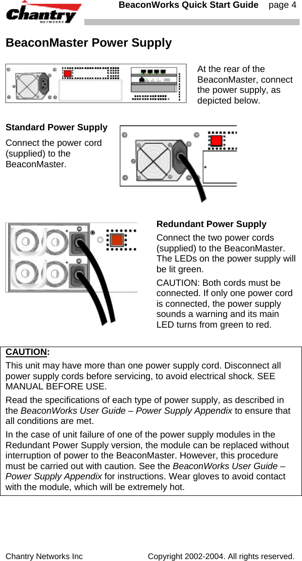
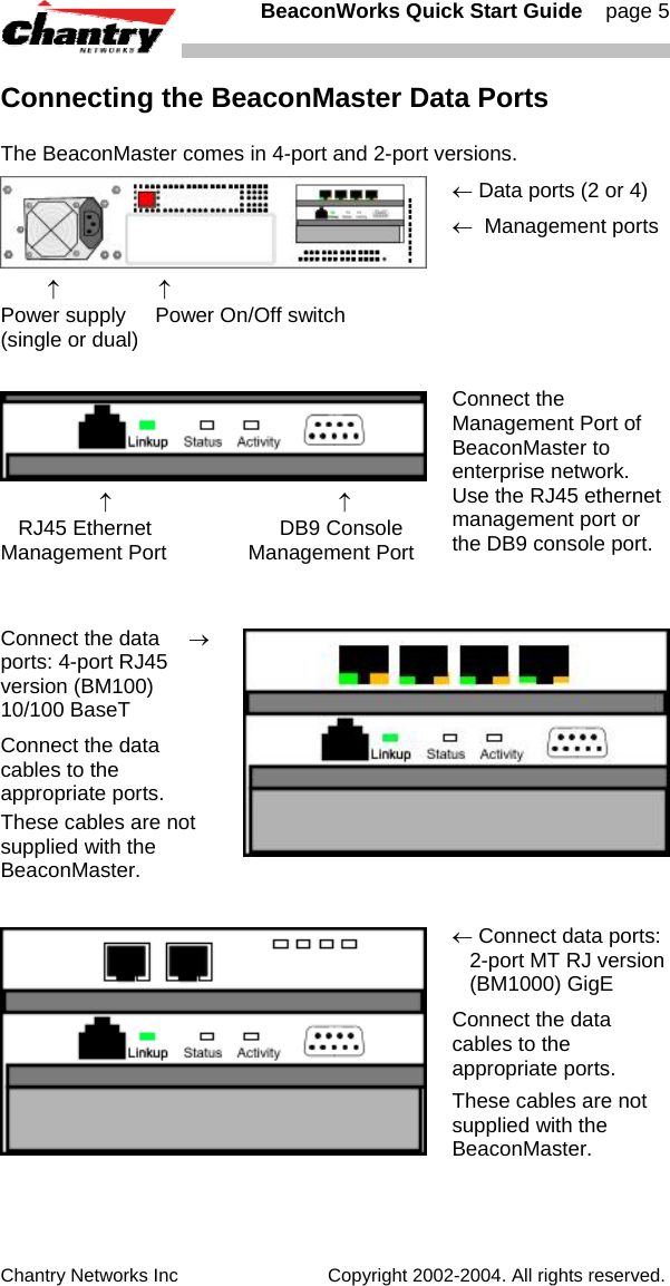
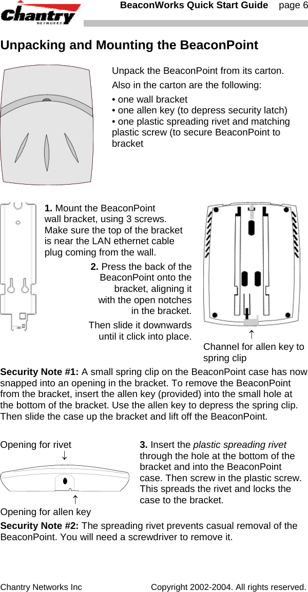
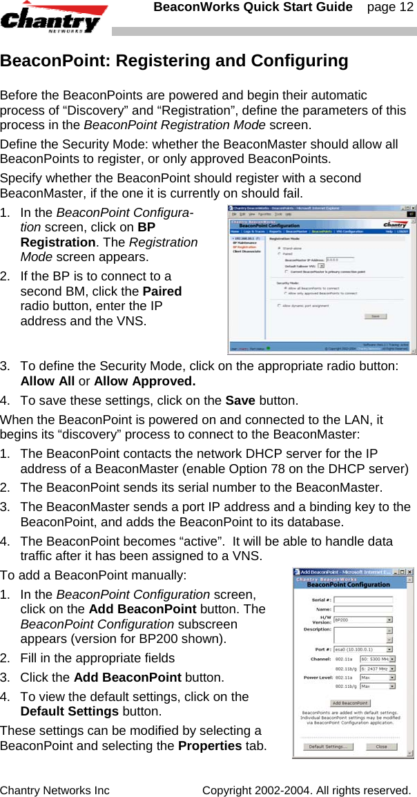
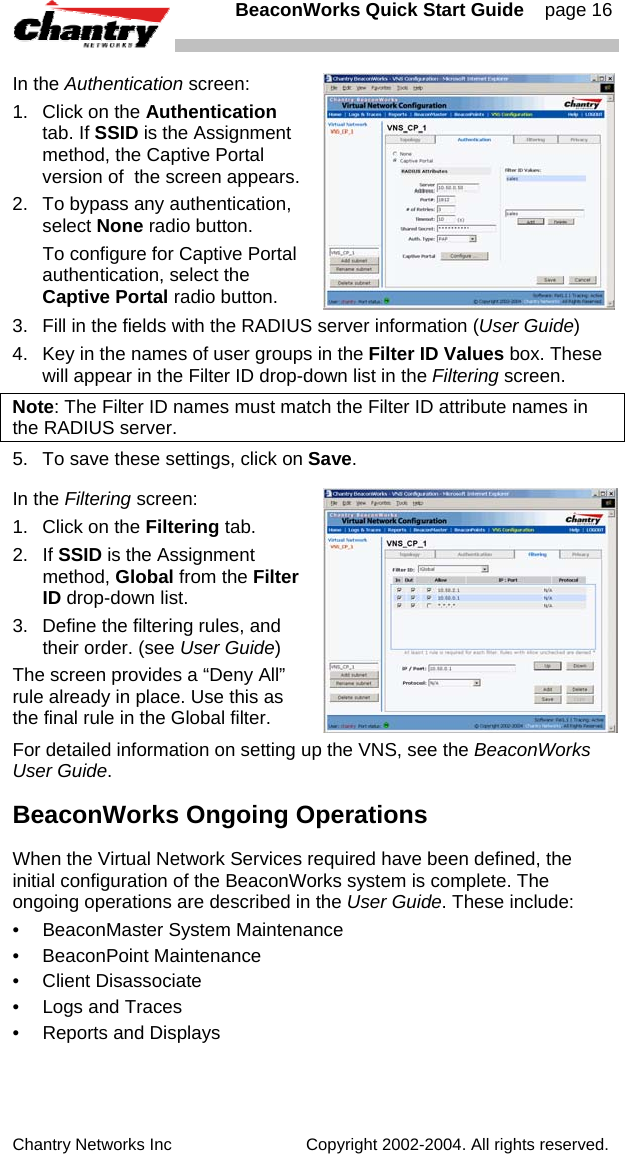
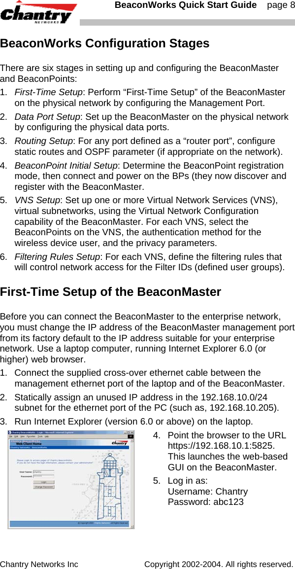
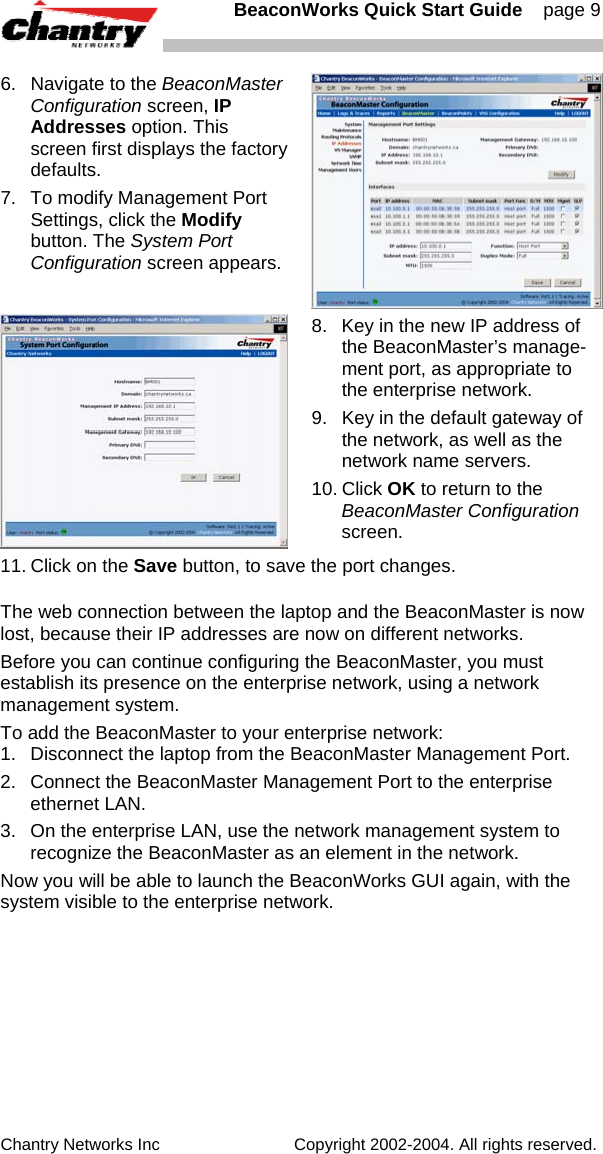
![BeaconWorks Quick Start Guide page 7 Chantry Networks Inc Copyright 2002-2004. All rights reserved. Connecting and Powering the BeaconPoint The BeaconPoint is powered in one of three ways: Power Over Ethernet (PoE) If your network is already set up with PoE, attach the LAN ethernet cable to the RJ45 ethernet connector in the top of the BeaconPoint. Power Over Ethernet: Adding PoE Injector If your network is not set up with PoE, you can provide power to the ethernet cable with a PoE injector. The PoE injector must be 802.3af compliant. The PoE injector is not provided with the BeaconPoint. Power by AC Adaptor An AC adaptor is not provided with the BeaconPoint. If you wish to use one, the specifications are: BP100 – Input: 120-240 VAC, Output Voltage DC 5V, max amps 2.00, max watts 10. BP200 – Input: 120-240 VAC, Output Voltage DC +6V, max amps 1.50, max watts 10. To use an adaptor, install the BeaconPoint within six feet of a wall outlet, attach the adaptor to the BeaconPoint and then plug the adaptor into the wall outlet. Note: For a list of recommended and tested devices (PoE Injectors or AC adaptors) for use with the BeaconPoint, contact Chantry Networks Customer Service, or go to www.chantrynetworks.com/site/support.html. [Optional]. Connect an AC/DC power supply (if PoE is not being used in your network) ↑ ↑ power LAN ethernet connector port connector In the top of the BeaconPoint, connect the LAN ethernet cable to the ethernet port. 4. Attach the LAN ethernet cable to the ethernet port of the BeaconPoint, OR If you are using the optional power adaptor (rather that Power-over-Ethernet), plug in the unit. Note: Before you power up the BeaconPoint (step 4), you should define the Registration Mode (BeaconPoint Configuration, BP Registration screen) in the User Interface of the BeaconMaster. See BeaconPoint: Registering and Configuring, p. 12, or the User Guide. Powering up the BeaconPoint initiates its automatic discovery and registration process. The parameters for this process should be set first. Before you can access the BeaconMaster User Interface, you must perform the First-Time Setup described next.](https://usermanual.wiki/Chantry-Networks/BP200E.quick-start-guide/User-Guide-442398-Page-7.png)
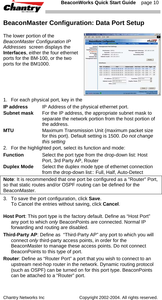
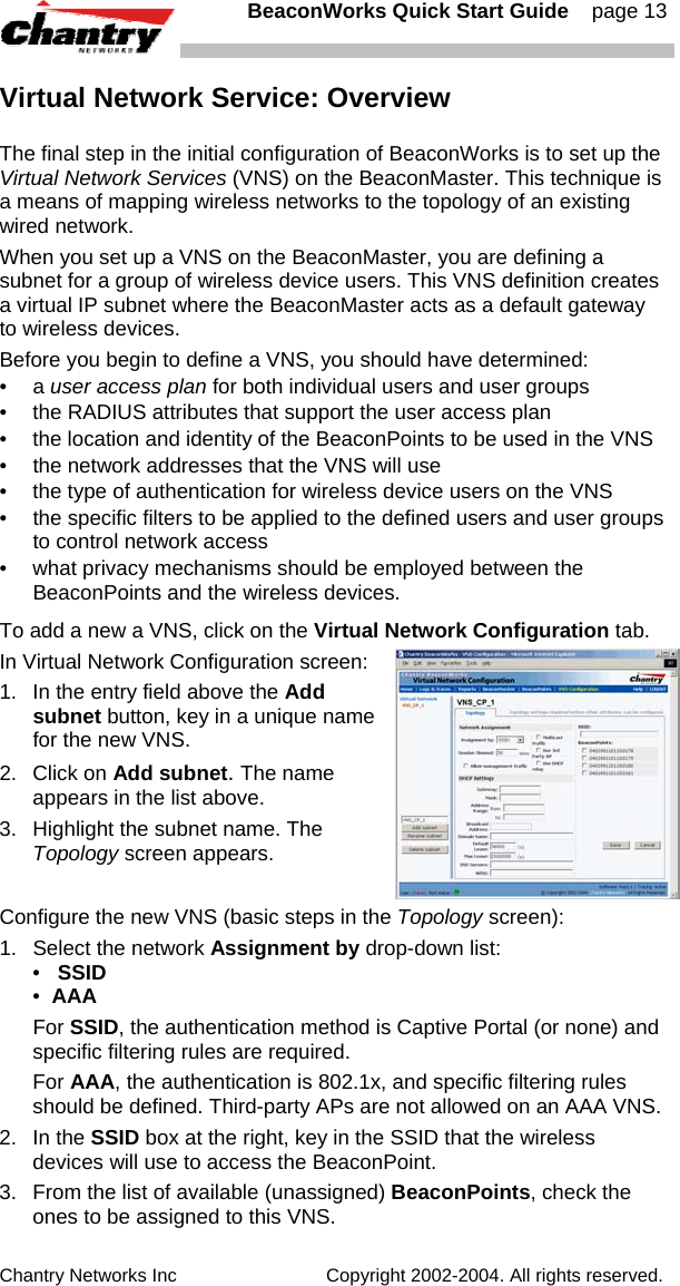
![BeaconWorks Quick Start Guide page 11 Chantry Networks Inc Copyright 2002-2004. All rights reserved. BeaconMaster Configuration: Static Routes It is recommended that one data port be configured as a "Router" port. Then you can define a default route to your enterprise network, either with a static route or by using OSPF protocol (Open Shortest Path First). This will enable the BeaconMaster for forward wireless packets with unknown destinations to the remainder of the network. You should also define a route to the RADIUS server on your network (if your network uses a RADIUS server). 1. Click on the BeaconMaster tab in any screen. The BeaconMaster Configuration screen appears. 2. In the left-hand portion of the screen, click on the Routing Protocols option. Then click the Static Routes tab. The Static Routes screen appears. 3. To add a new route, click in the Destination Address field, and key in the destination IP address of a packet. [The destination network IP address that this static route applies to. Packets with this destination address will be sent to the Destination below.] To define a default static route for any unknown address not in the routing table, key in 0.0.0.0 4. Key in the Subnet Mask. For the IP address, the appropriate subnet mask to separate the network portion from the host portion For the default static route for any unknown address, key in 0.0.0.0. 5. Select an outbound destination for the packets, either: Click on the radio button in the Gateway field, and key in the IP address of the gateway (the IP address of the specific router port or gateway, on the same subnet as the BeaconMaster, to which to route these packets; that is, the IP address of the next hop between the BeaconMaster and the packet's ultimate destination) , or Click on the Interface button, and select a port from the list. 6. Click on the Add button. The new route appears in the list. 7. Click on Save to update the routing table on the BeaconMaster. [See the BeaconWorks User Guide for steps to set up OSPF routing.] To view the static routes that have been defined for the BeaconMaster, click on the View Forwarding Table tab. This displays the Forwarding Table Screen from the Reports & Displays area of the user interface.](https://usermanual.wiki/Chantry-Networks/BP200E.quick-start-guide/User-Guide-442398-Page-11.png)