Chantry Networks BP200E ACCESS POINT WITH WLAN AND UNII User Manual Chantry Networks Inc BeaconWorks User Guide
Chantry Networks Inc. (a Siemens Company) ACCESS POINT WITH WLAN AND UNII Chantry Networks Inc BeaconWorks User Guide
Contents
USERS MANUAL 1
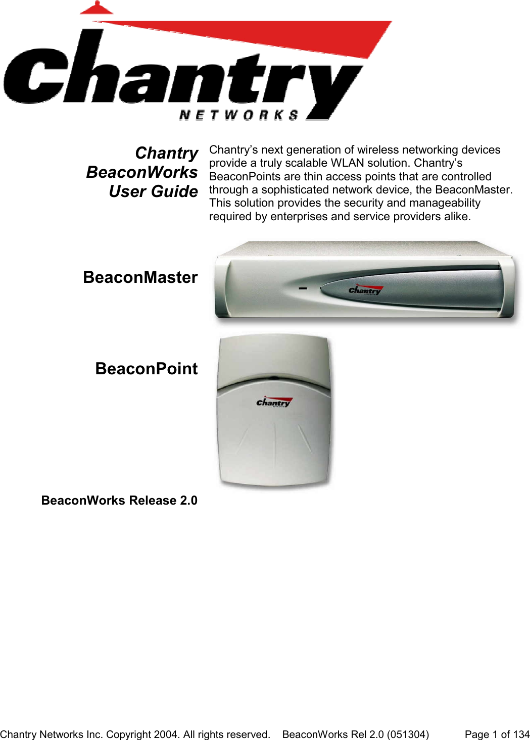
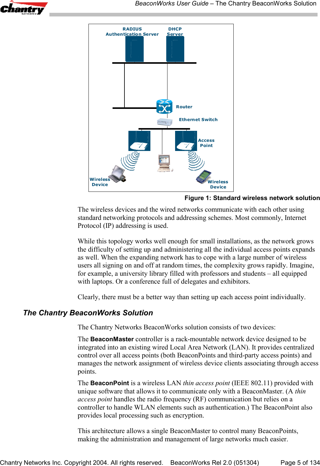
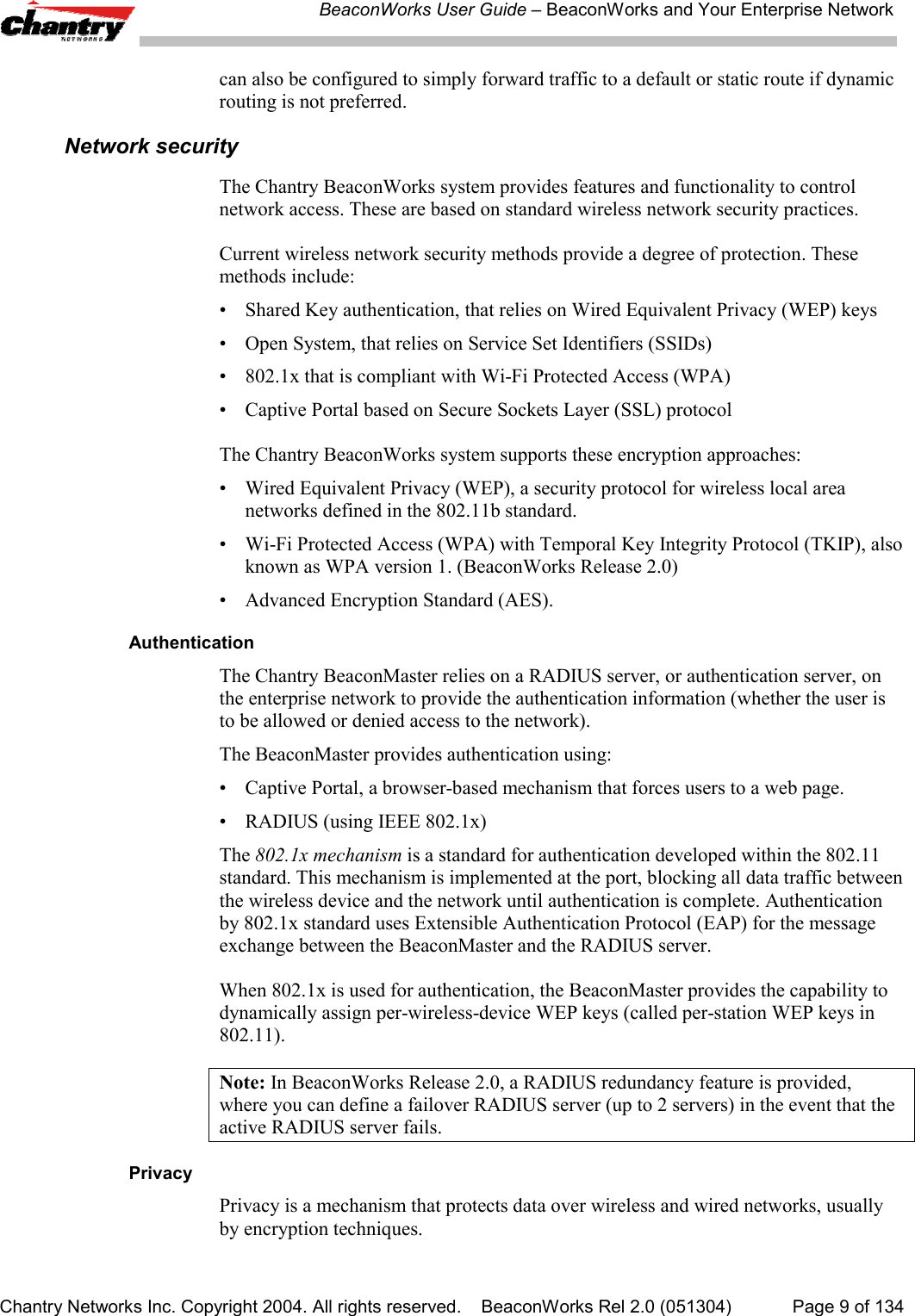
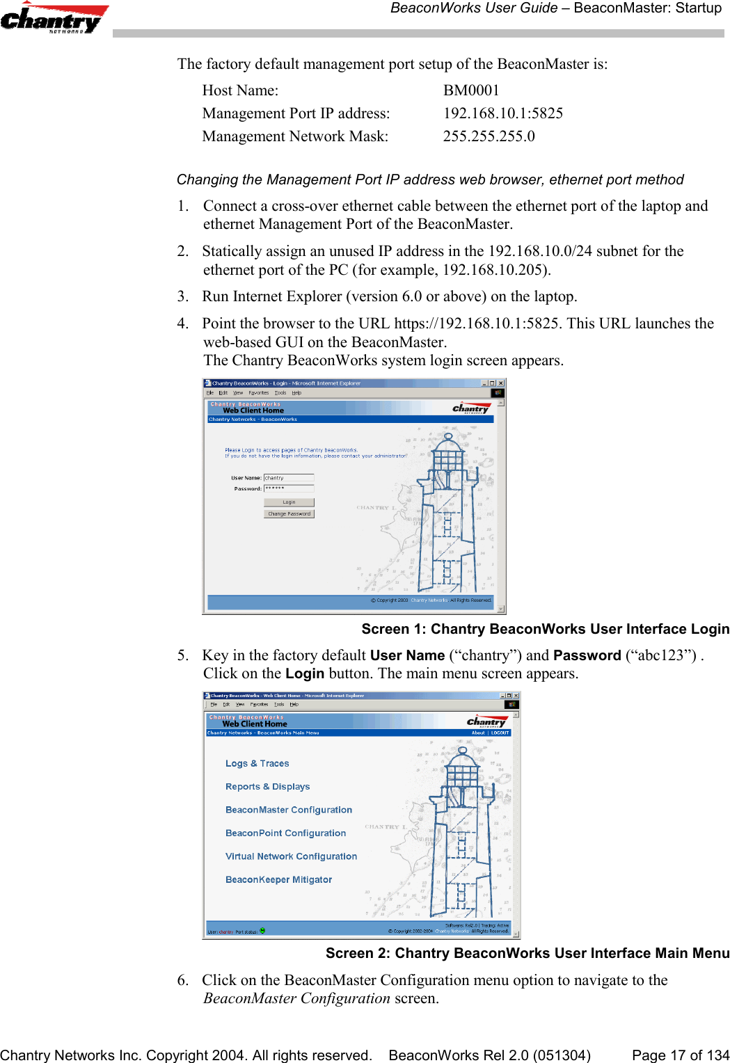
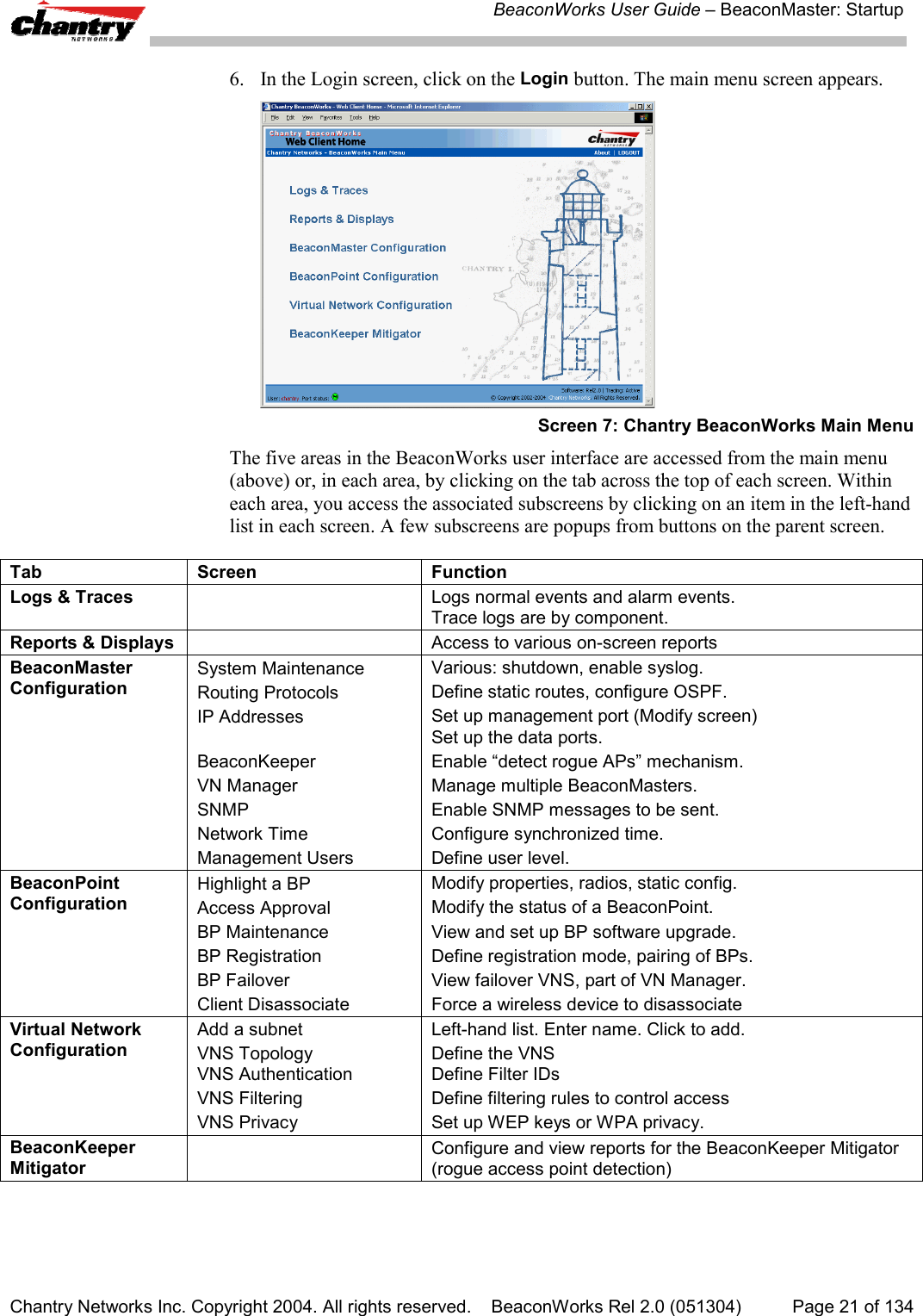
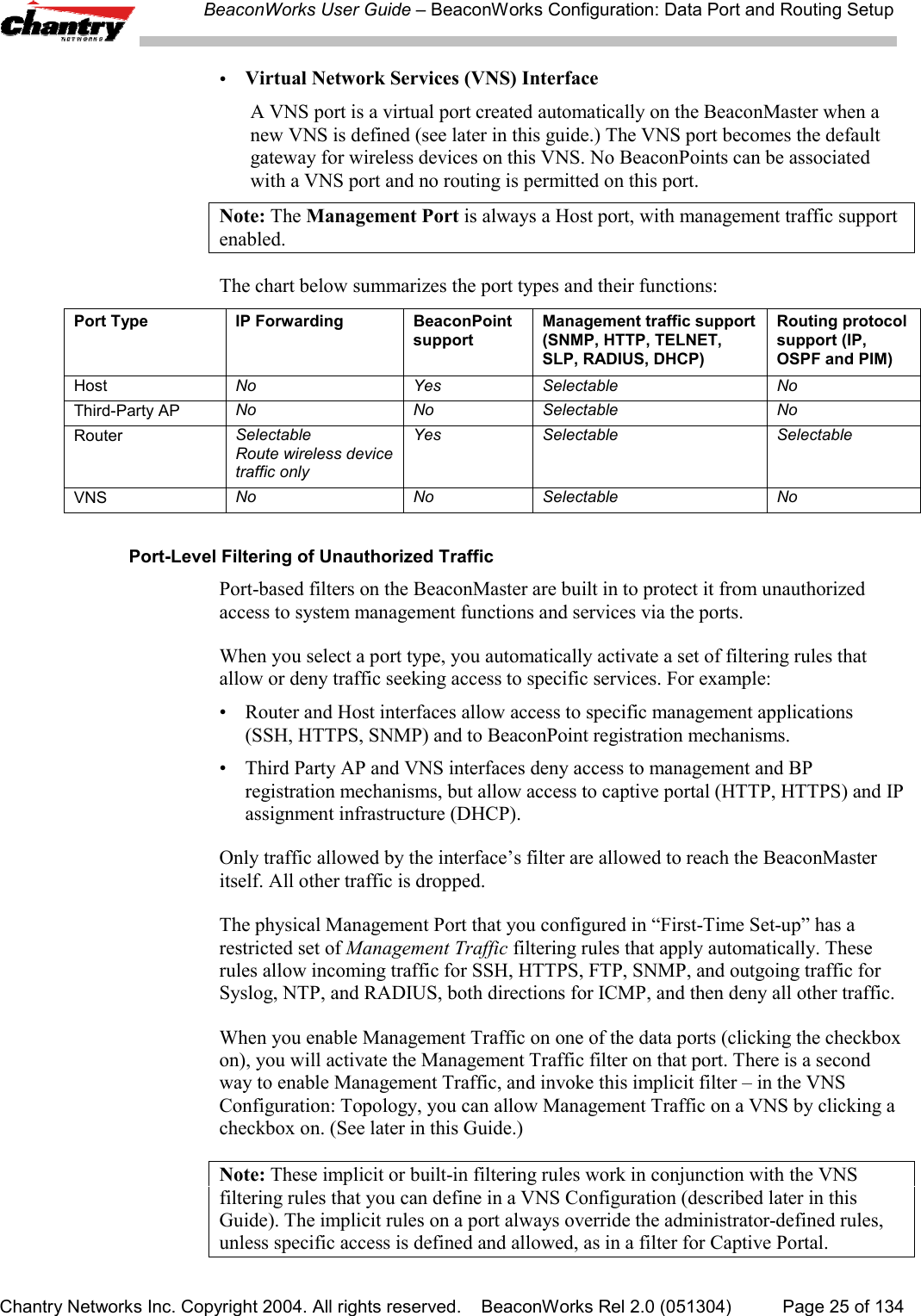
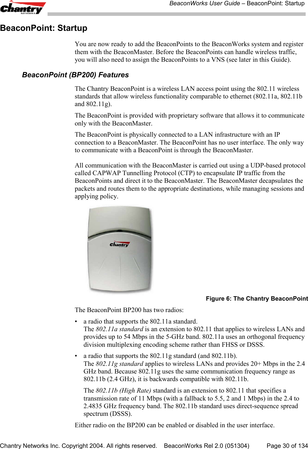
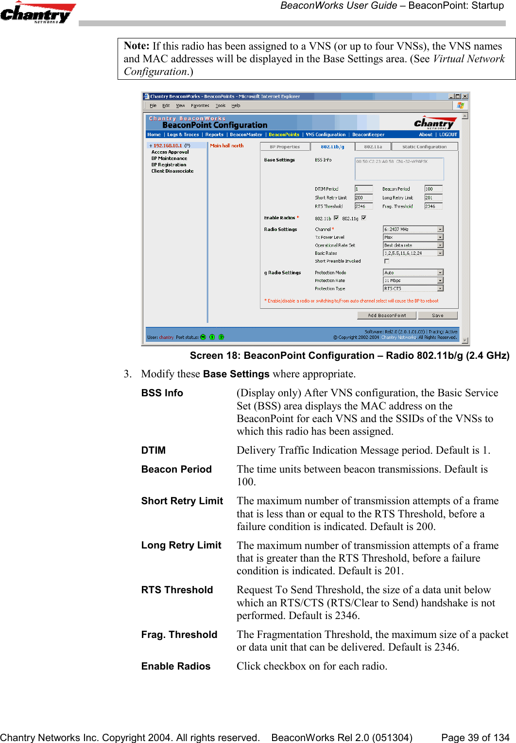
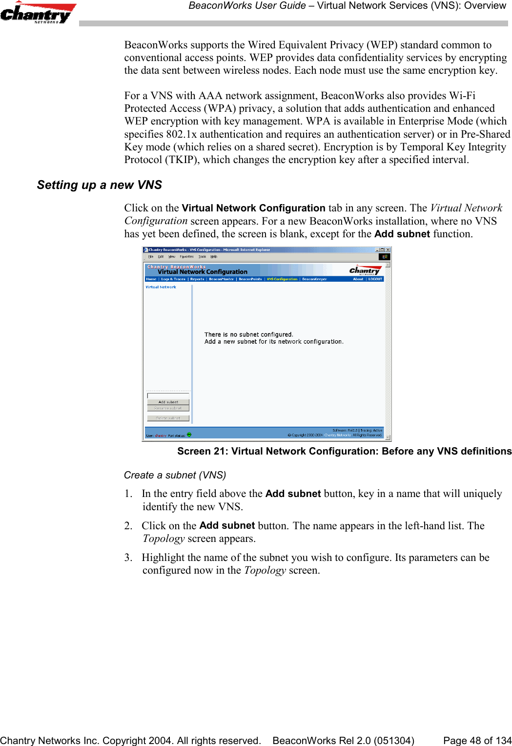
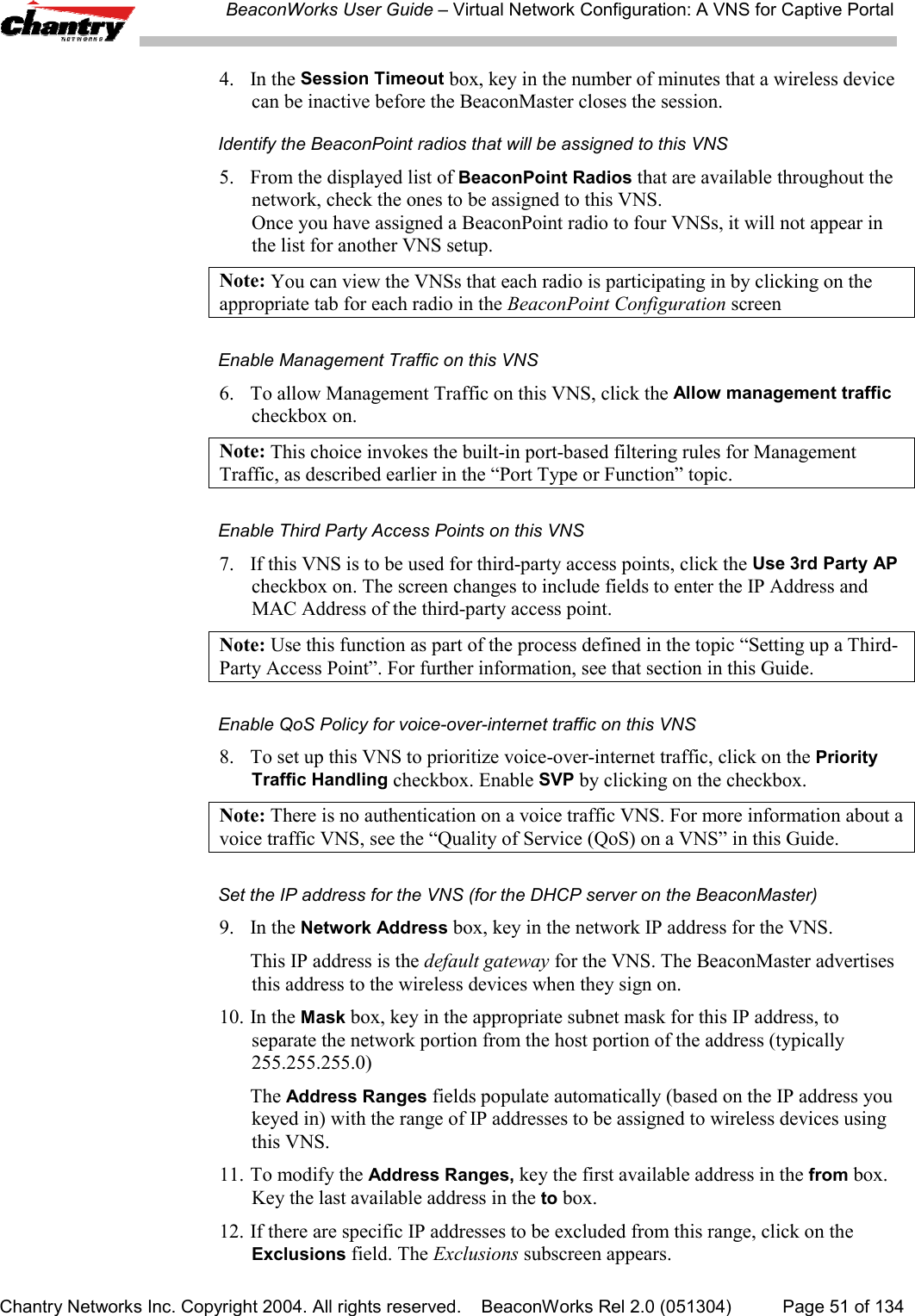
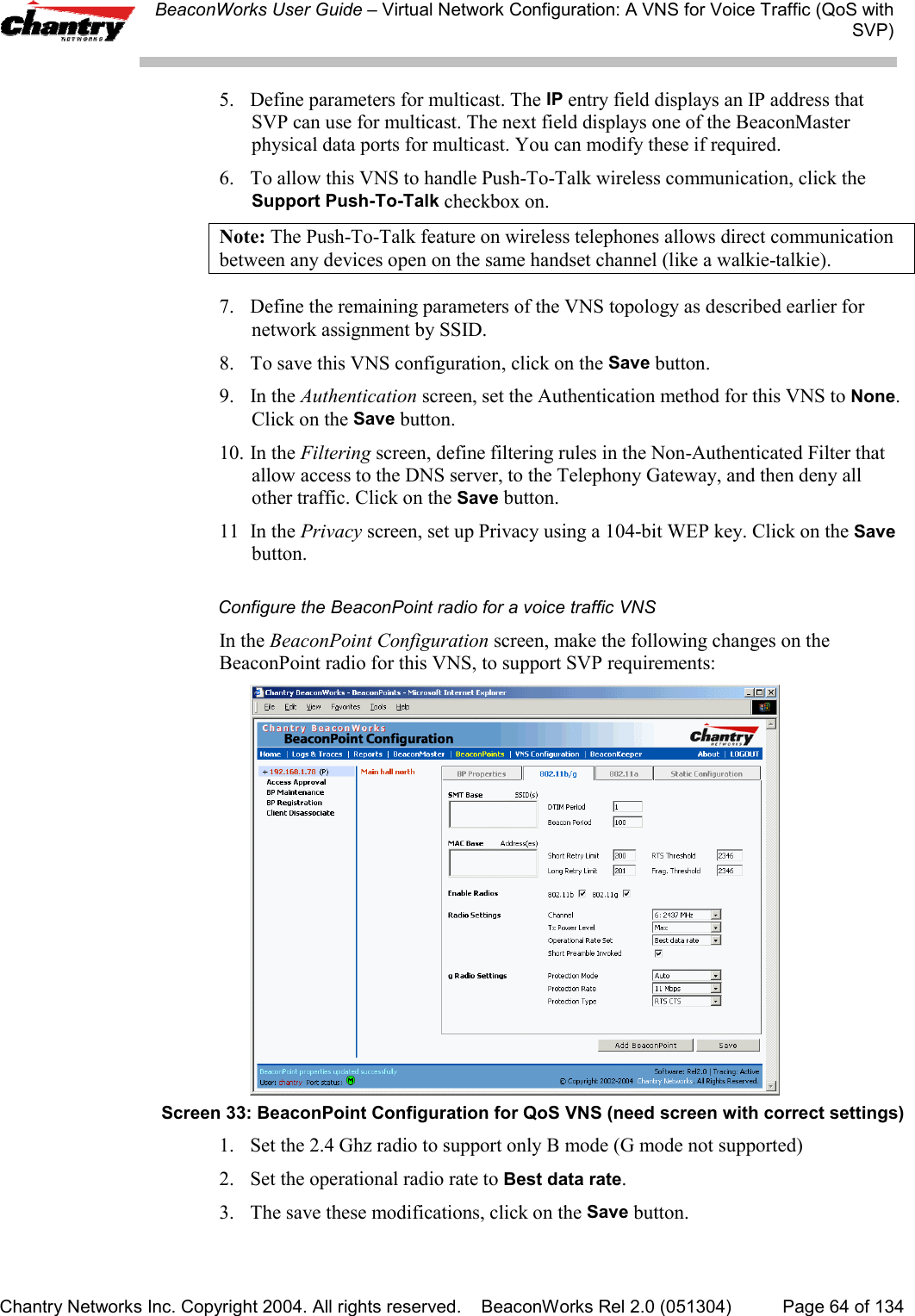
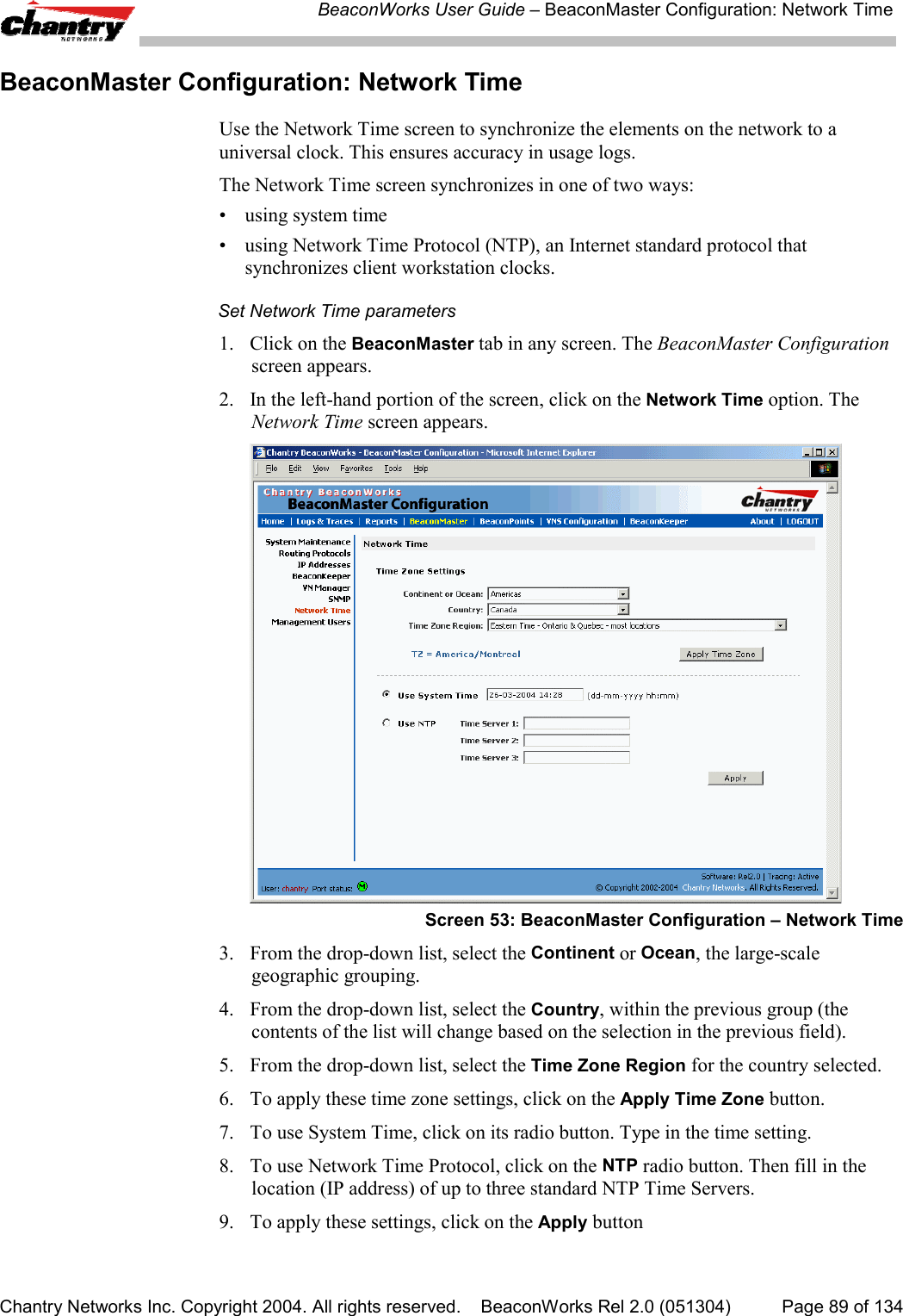
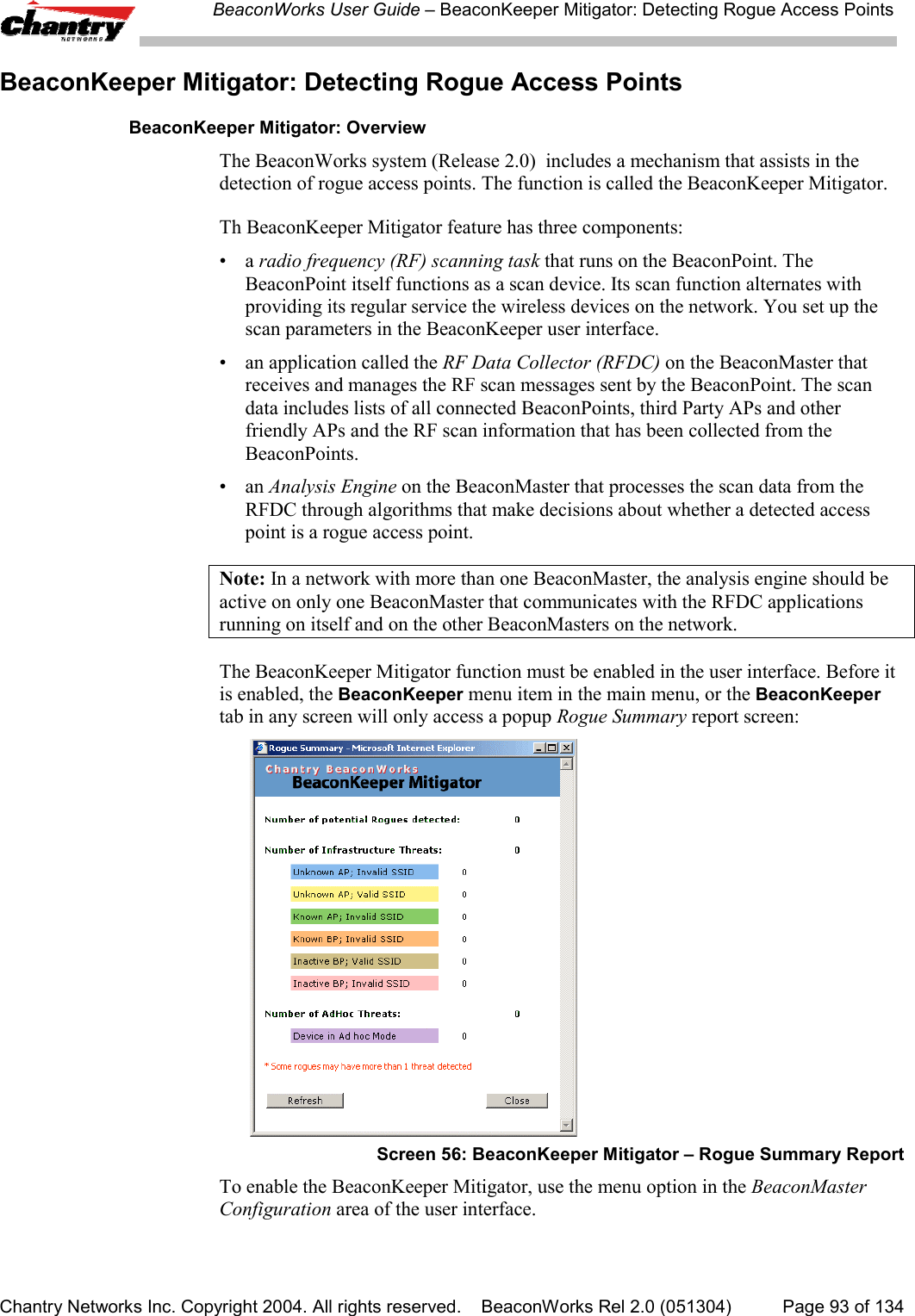
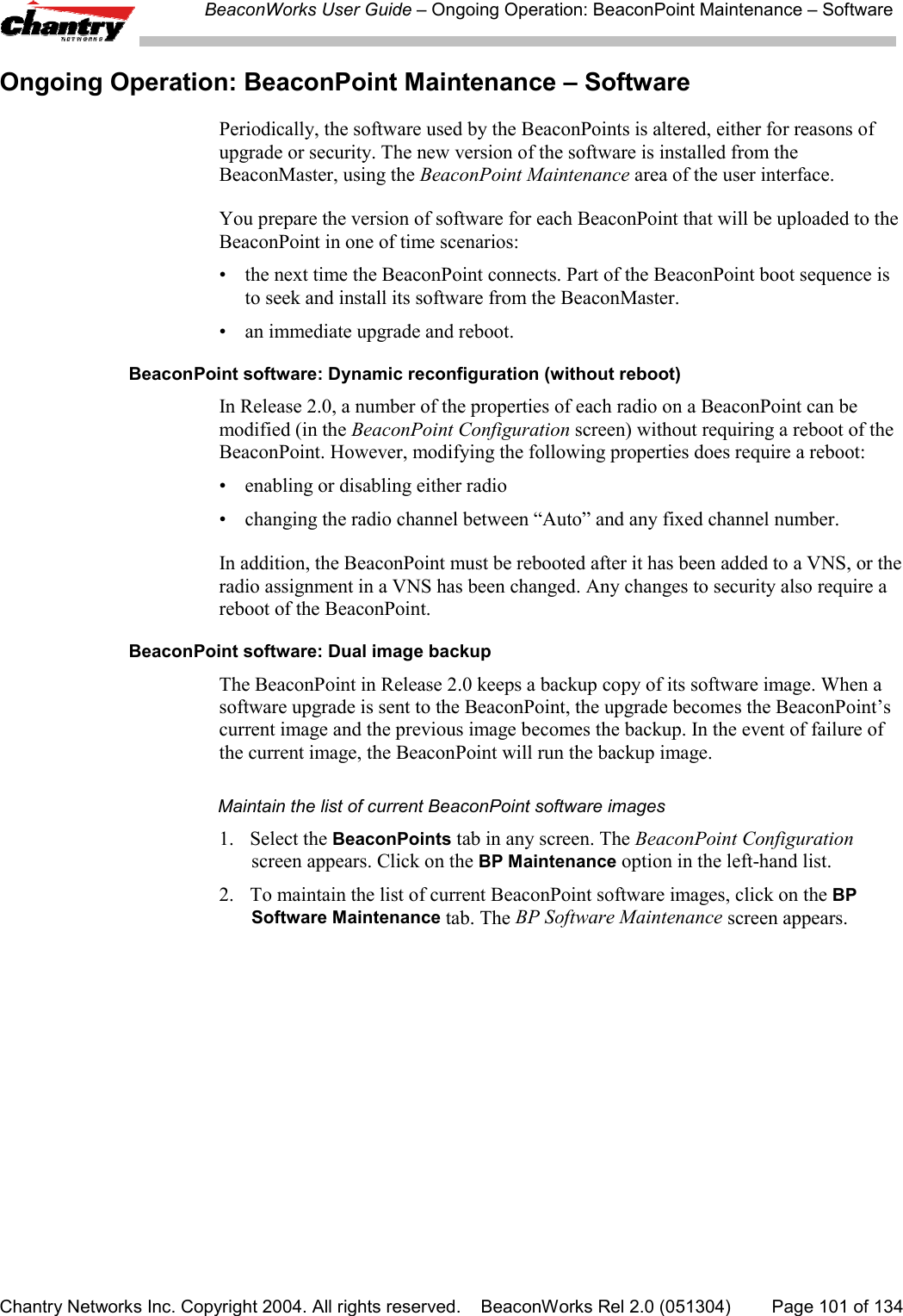
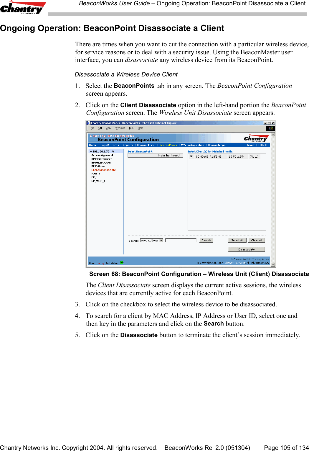
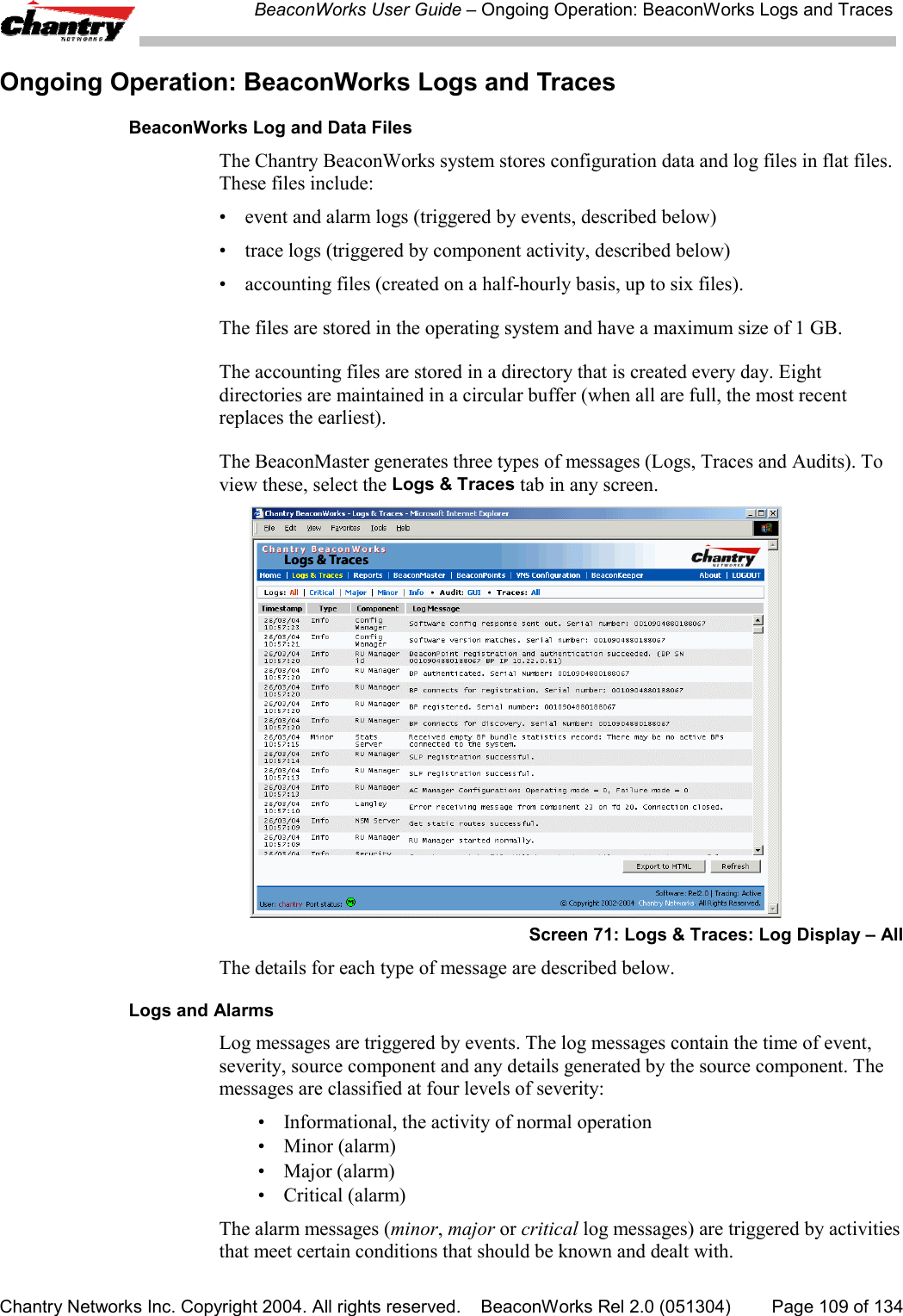
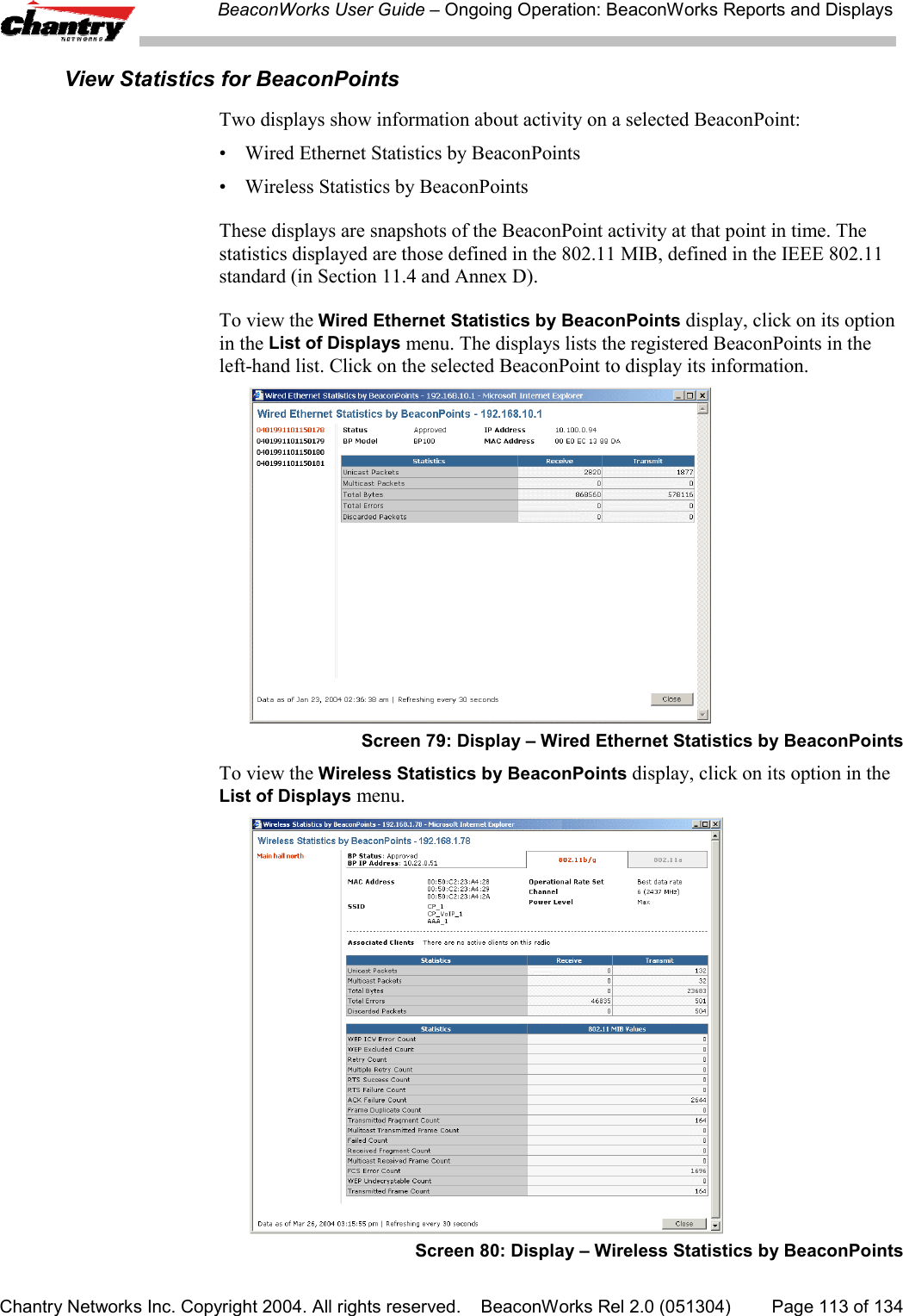
![BeaconWorks User Guide – BeaconWorks Configuration: Data Port and Routing SetupChantry Networks Inc. Copyright 2004. All rights reserved. BeaconWorks Rel 2.0 (051304) Page 26 of 134Setting up Static RoutesIt is recommended that one of the data ports be configured as a “Router” port. Thenyou can define a default route to your enterprise network, either with a static route orby using OSPF protocol. This will enable the BeaconMaster to forward wirelesspackets to the remainder of the network.Setting up a Static Route on the BeaconMaster1. Click on the BeaconMaster tab in any screen. The BeaconMaster Configurationscreen appears.2. In the left-hand portion of the screen, click on the Routing Protocols option.Then click the Static Routes tab. The Static Routes screen appears.Screen 9: BeaconMaster Configuration – Static Routes3. To add a new route, click in the Destination Address field, and key in thedestination IP address of a packet.[The destination network IP address that this static route applies to. Packets withthis destination address will be sent to the Destination below.]To define a default static route for any unknown address not in the routing table,key in 0.0.0.04. Key in the Subnet Mask. For the IP address, the appropriate subnet mask toseparate the network portion from the host portion of the address (typically255.255.255.0)For the default static route for any unknown address, key in 0.0.0.0.5. Select an outbound destination for the packets, either:Click on the radio button in the Gateway field, and key in the IP address of thegateway (the IP address of the specific router port or gateway, on the same subnetas the BeaconMaster, to which to route these packets; that is, the IP address of thenext hop between the BeaconMaster and the packet’s ultimate destination) ,](https://usermanual.wiki/Chantry-Networks/BP200E.USERS-MANUAL-1/User-Guide-474549-Page-26.png)
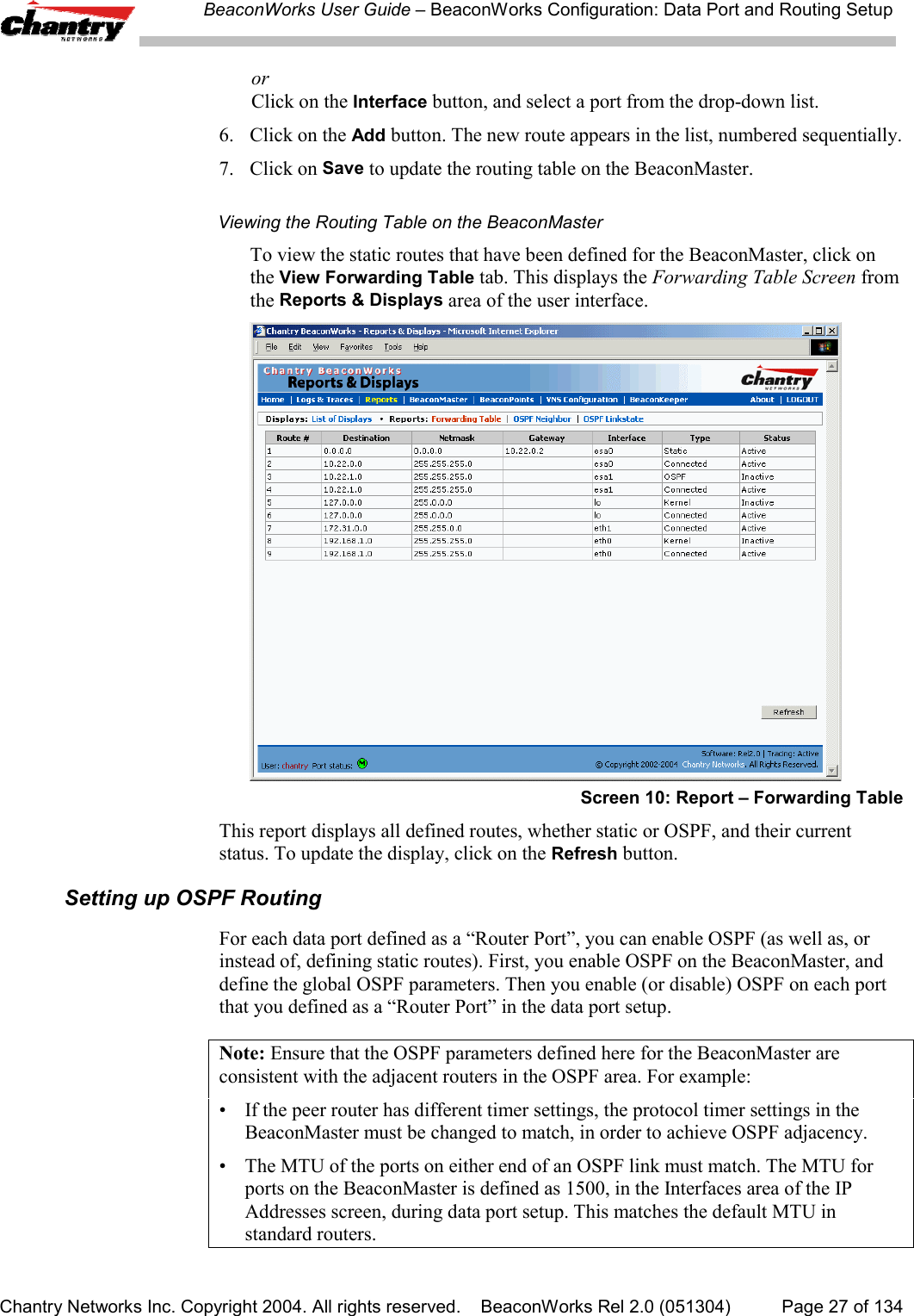
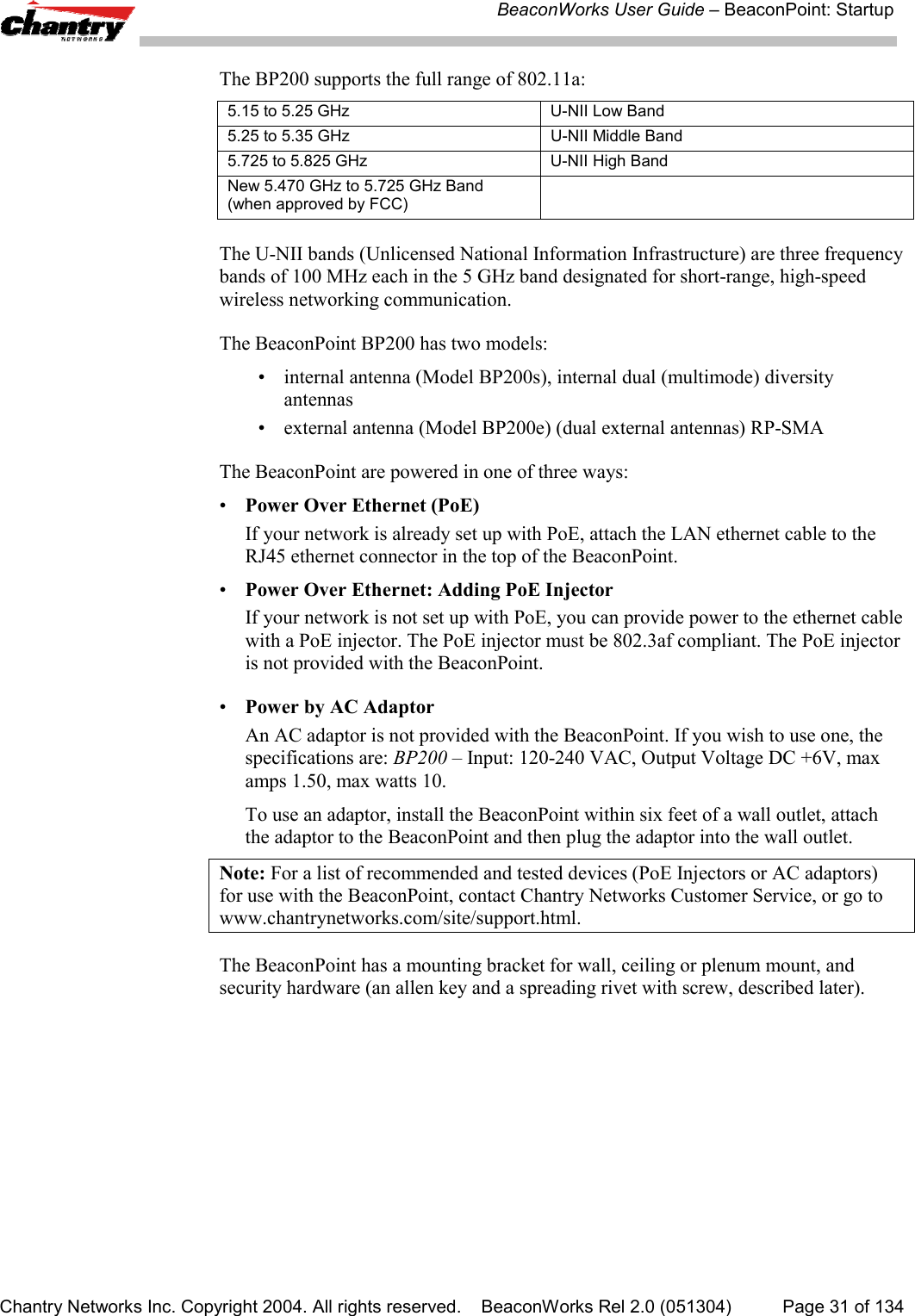
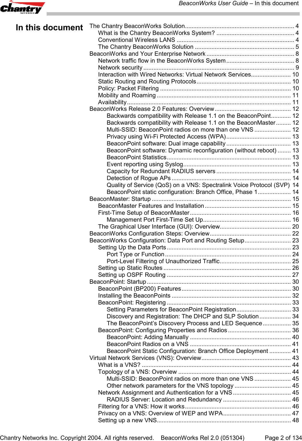
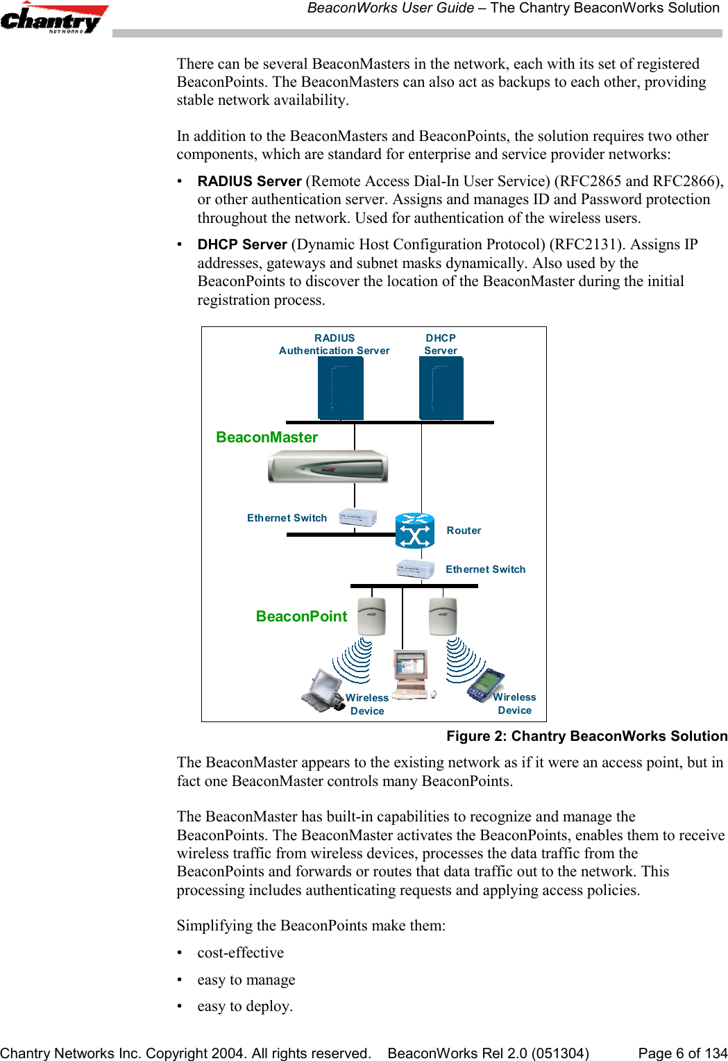
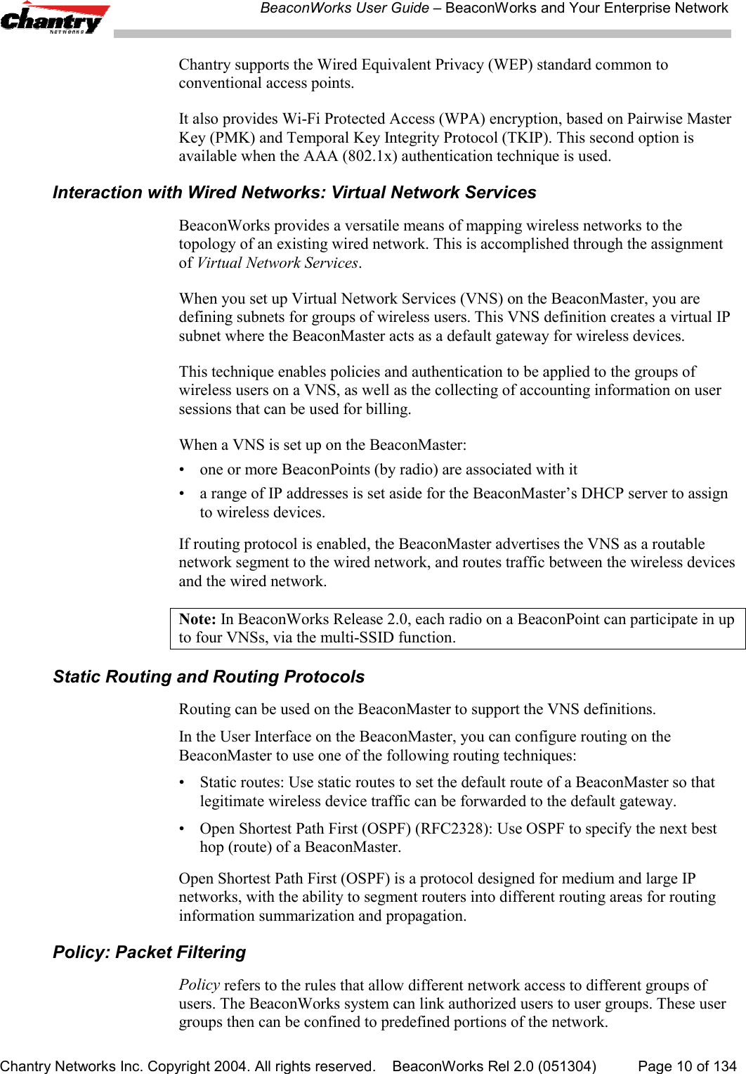
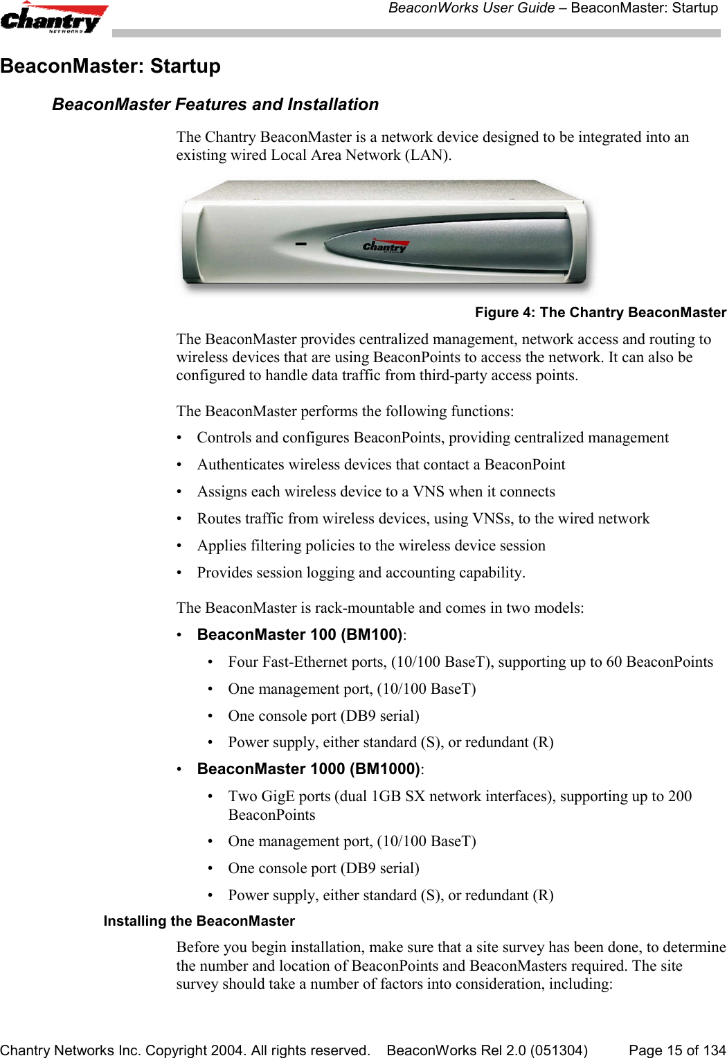
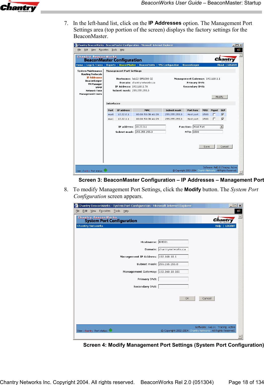
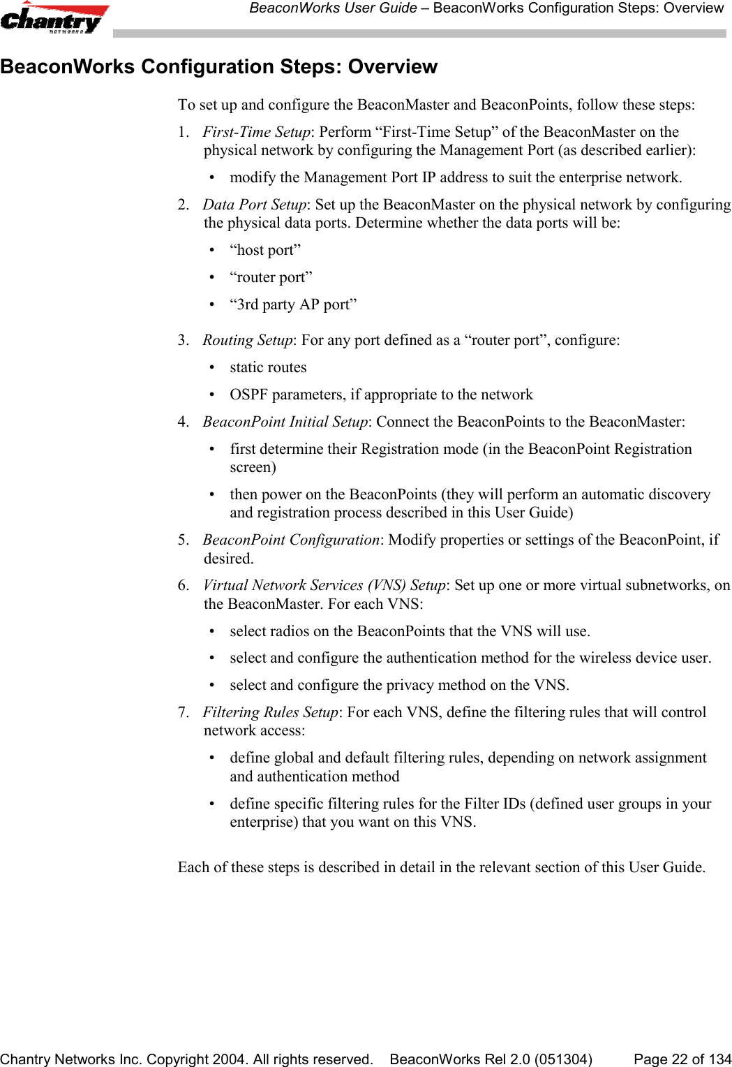
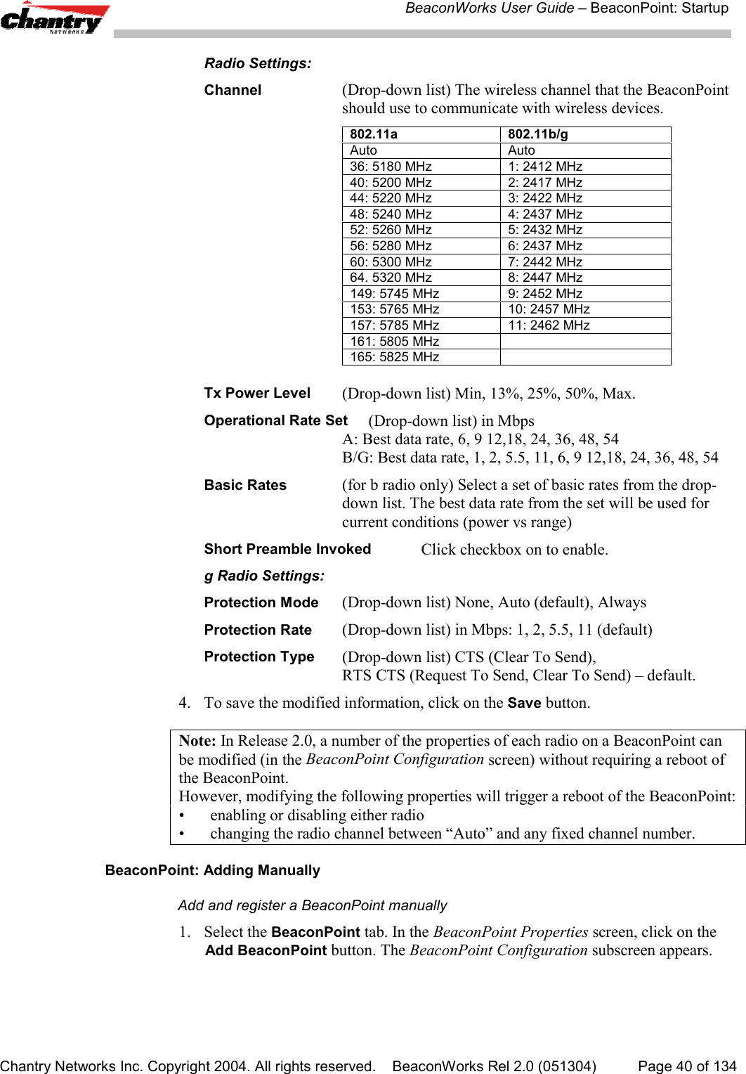
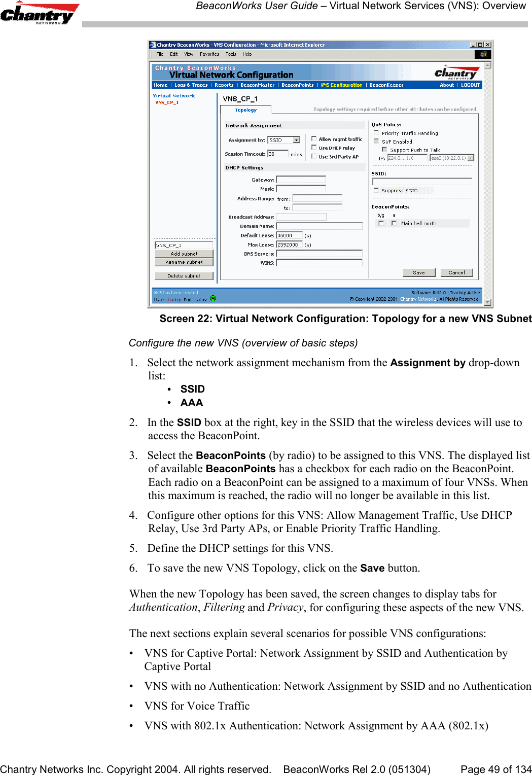
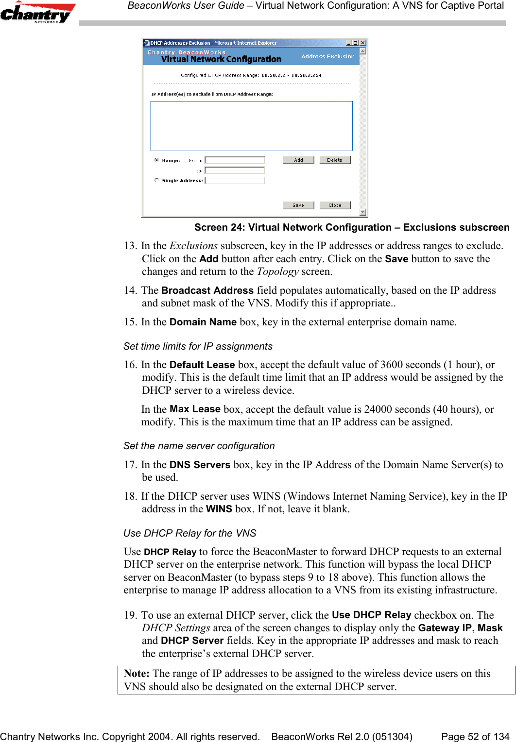
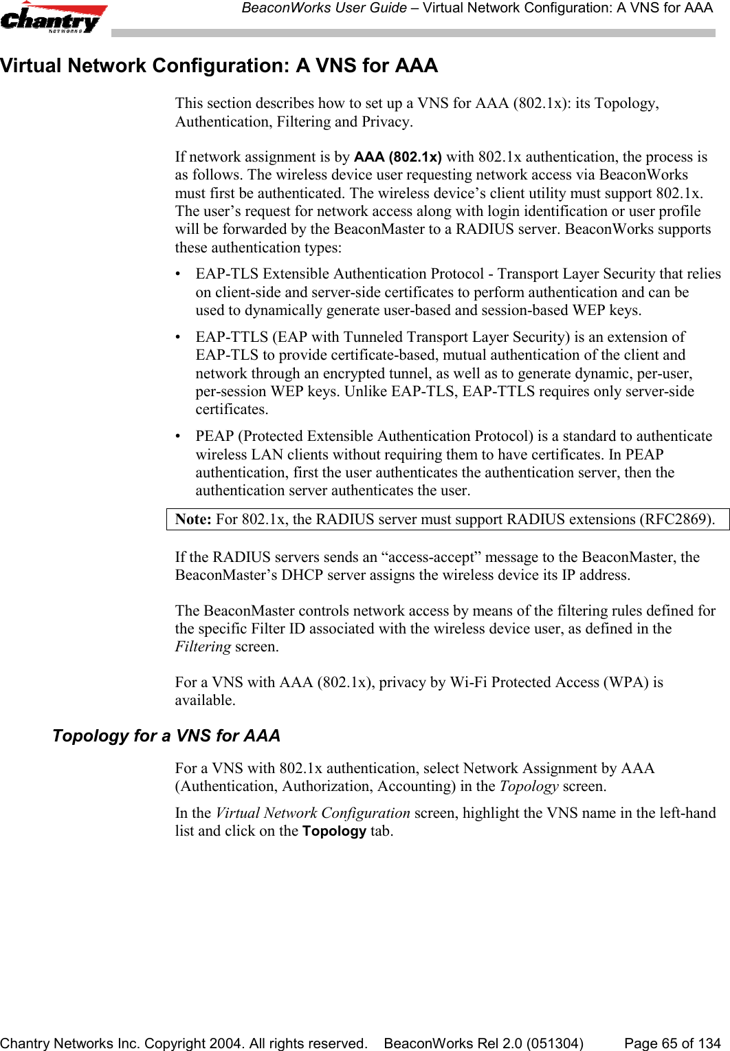
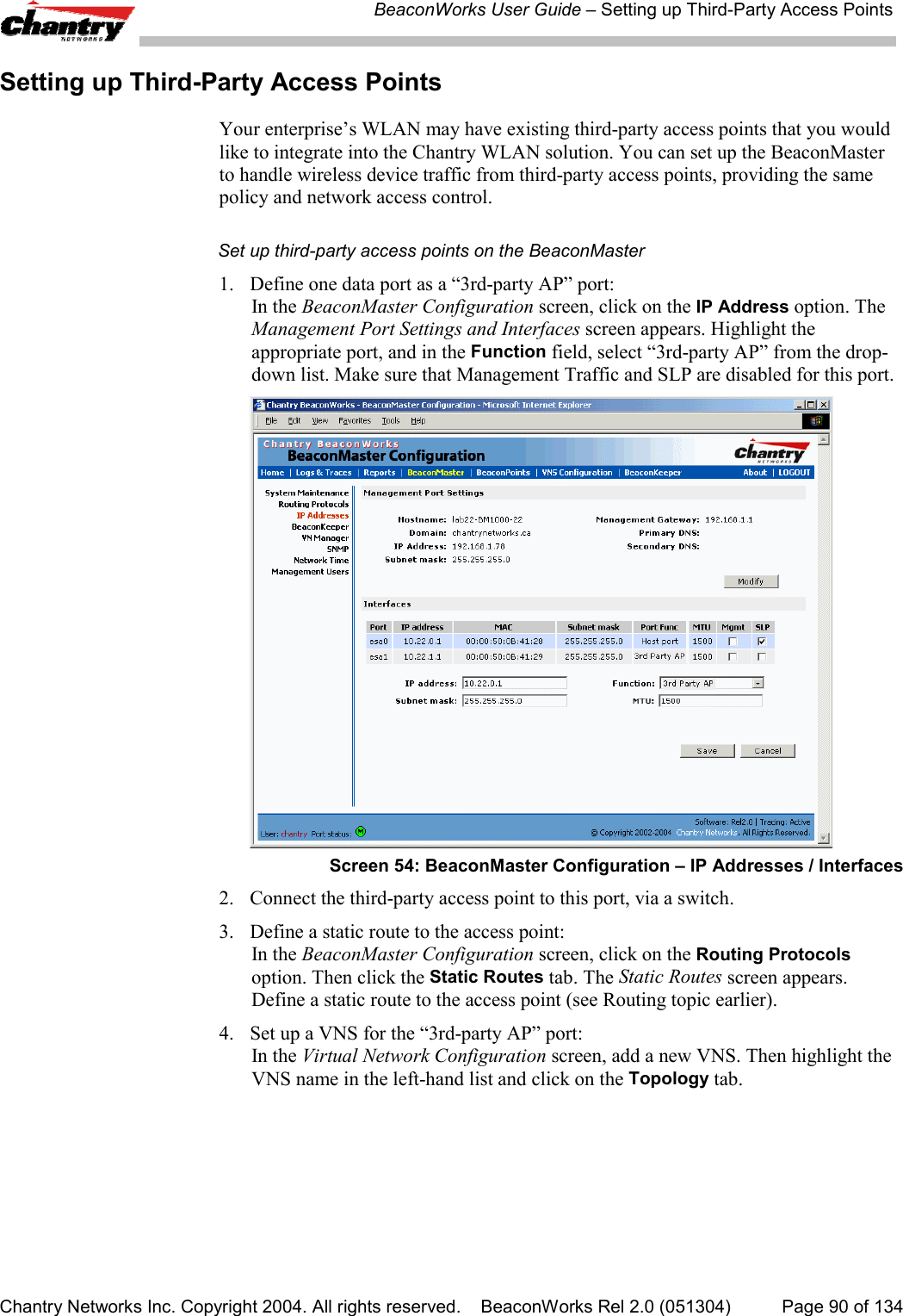
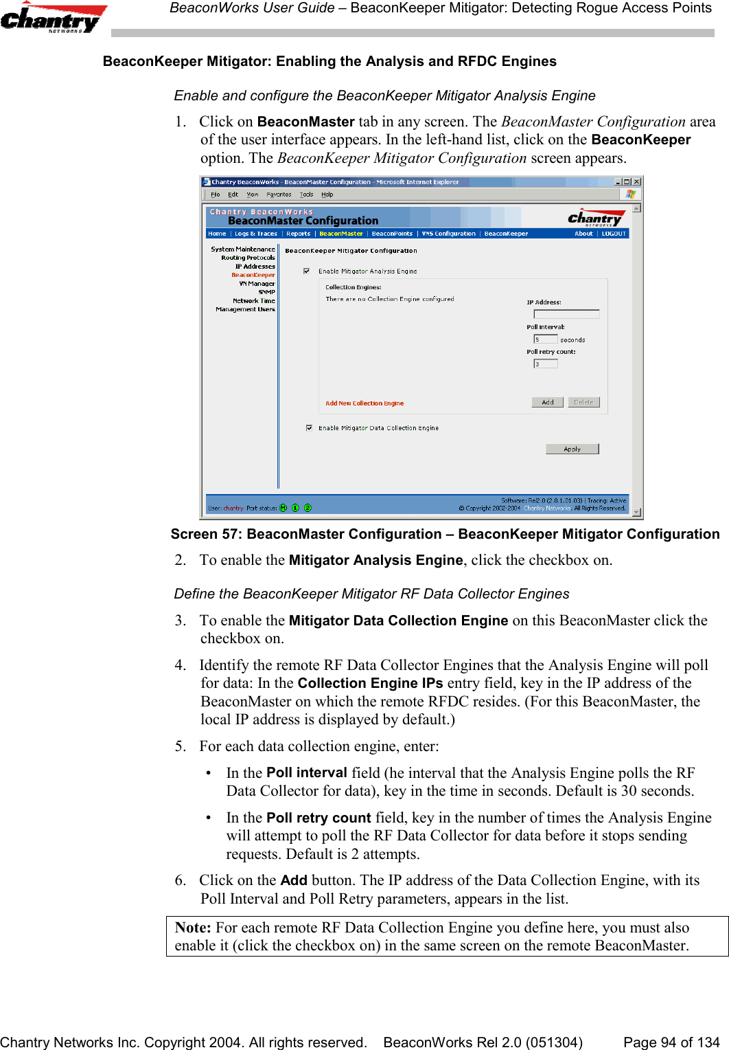
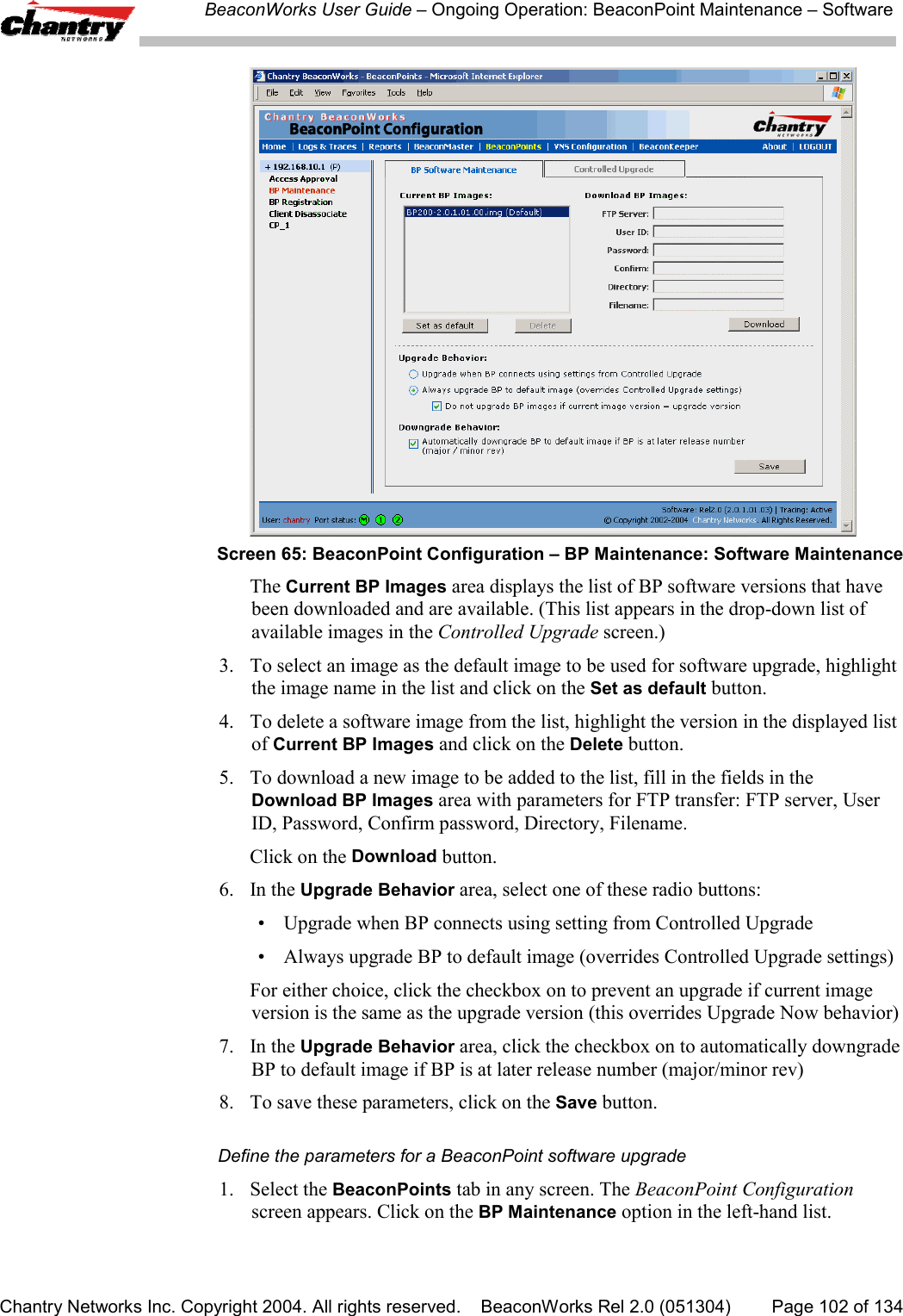
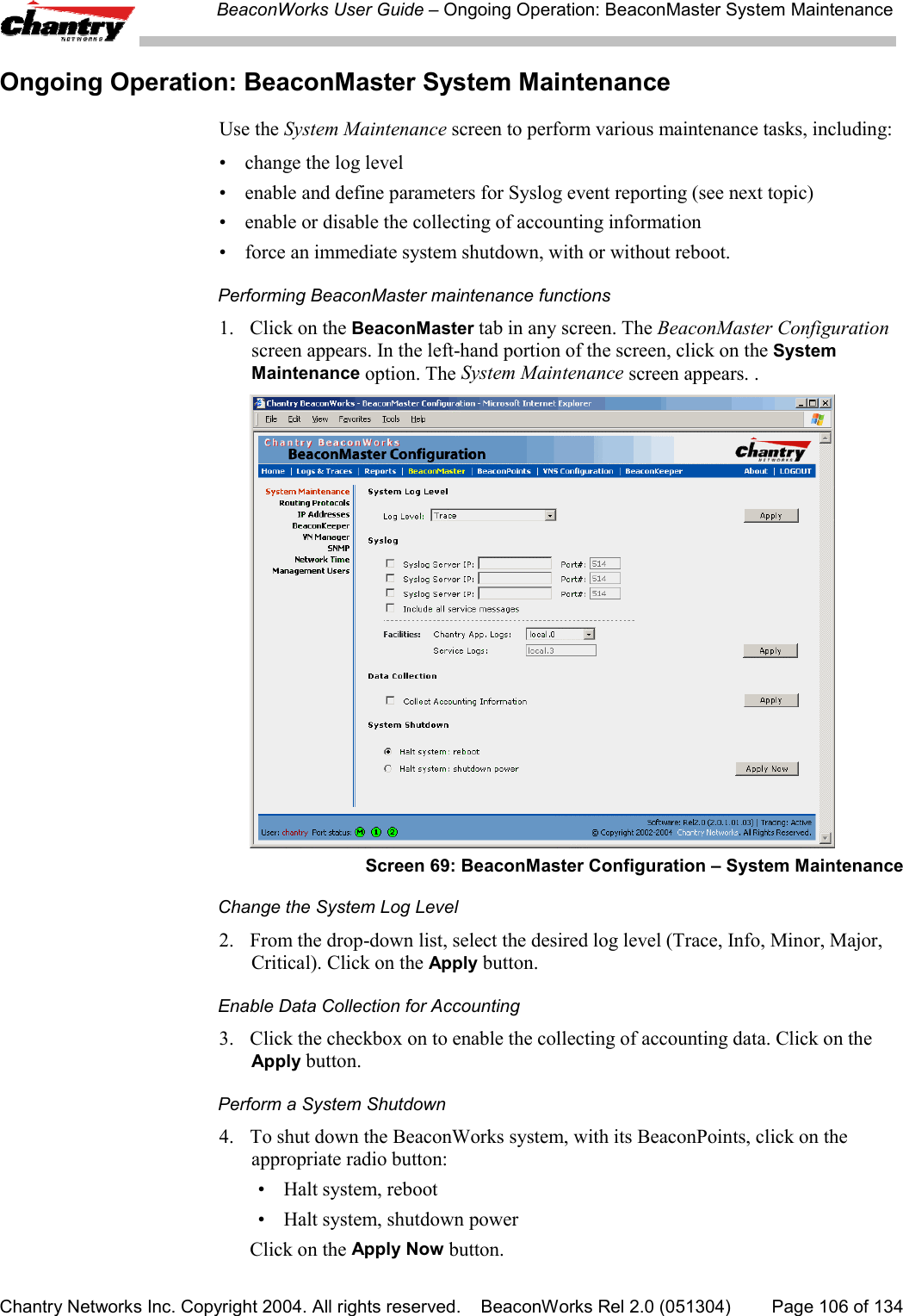
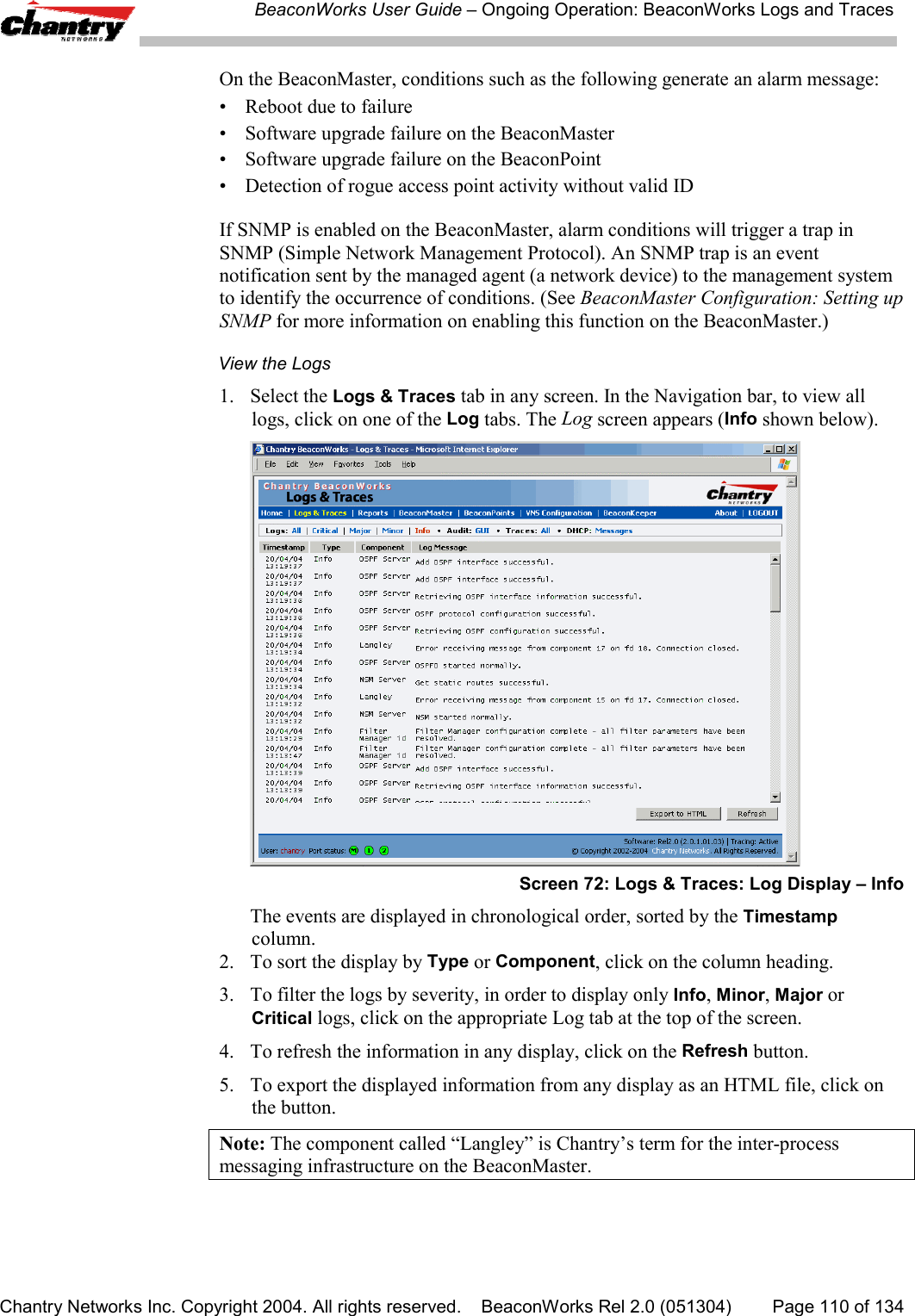
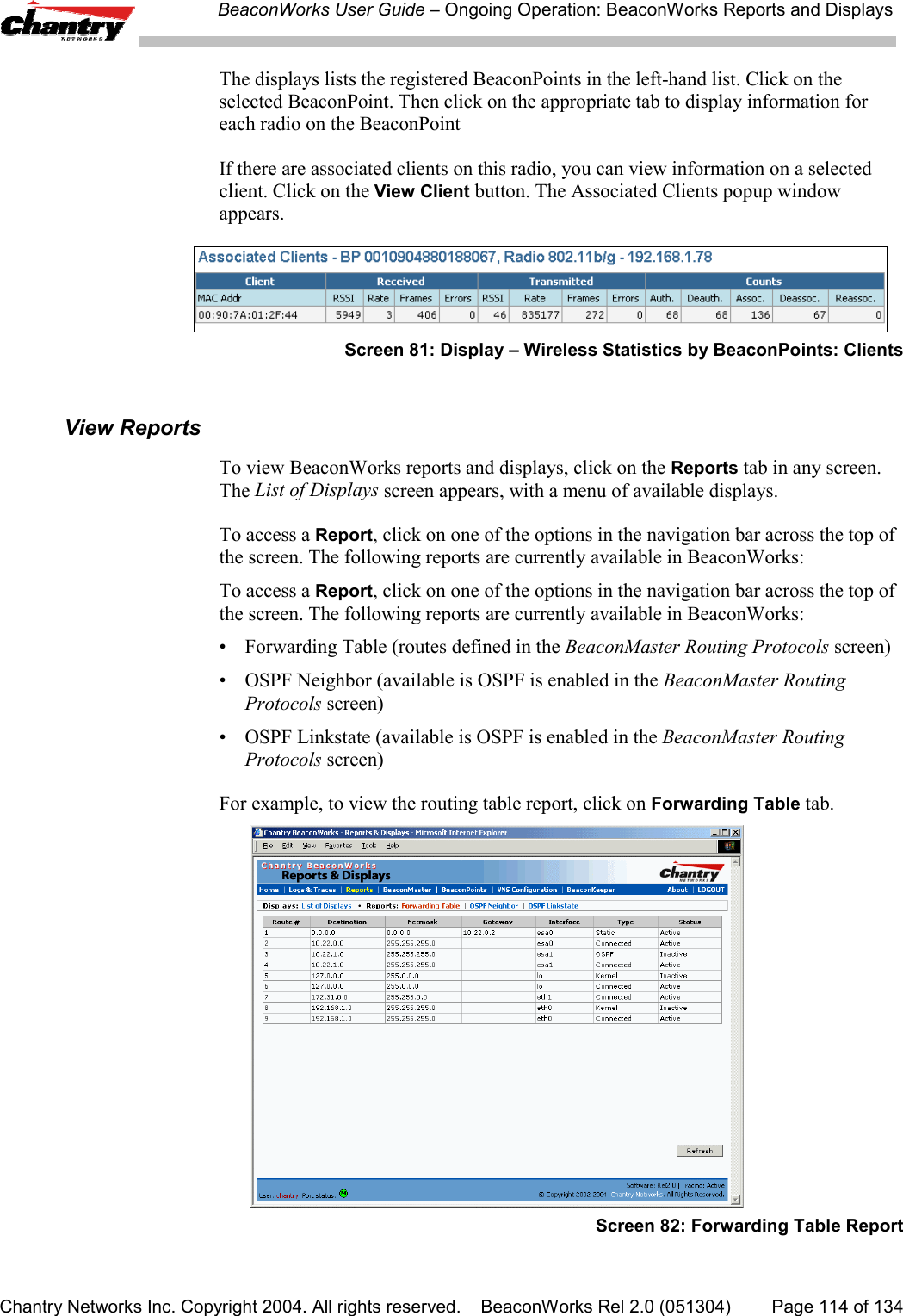
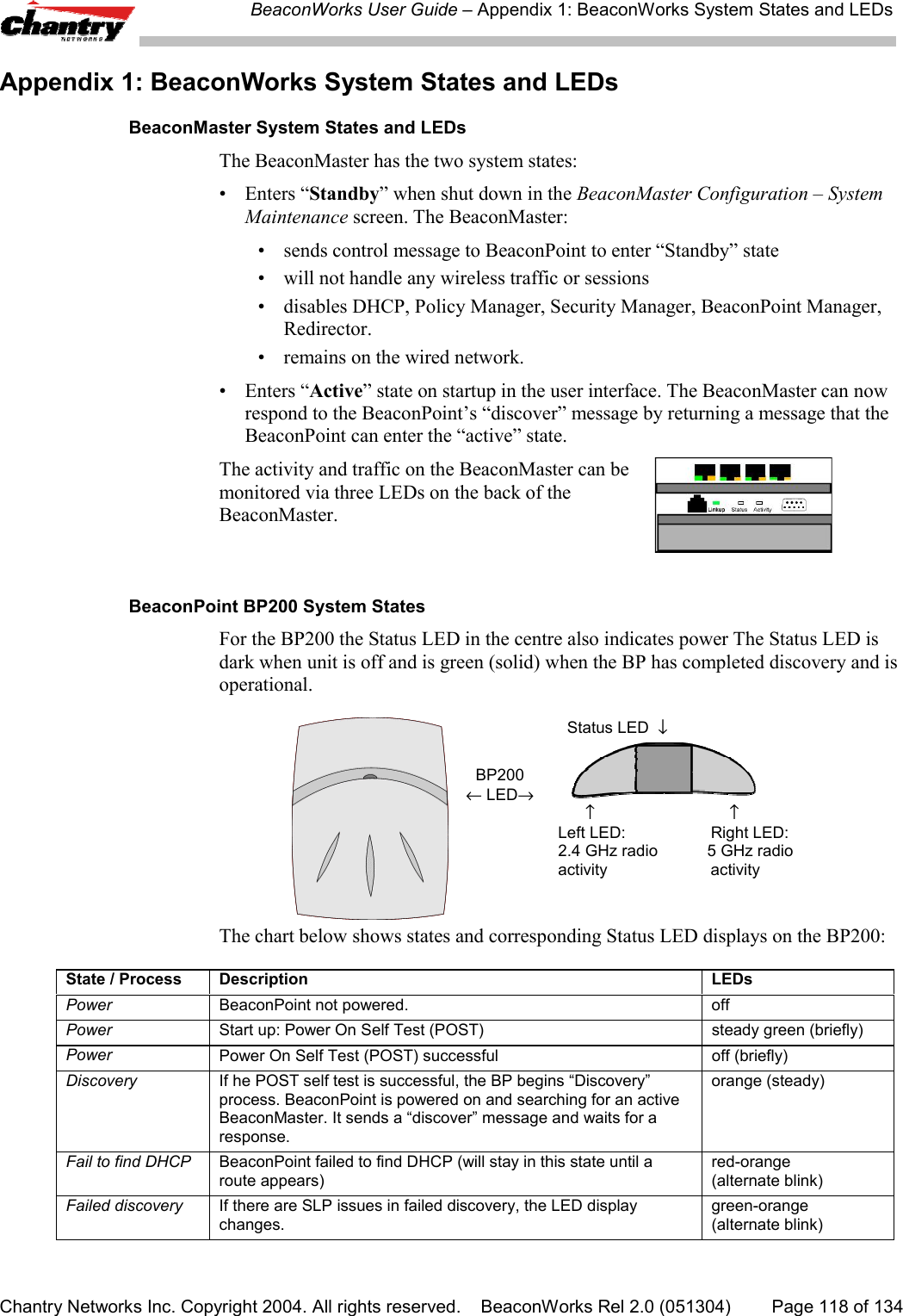
![BeaconWorks User Guide – BeaconPoint: StartupChantry Networks Inc. Copyright 2004. All rights reserved. BeaconWorks Rel 2.0 (051304) Page 35 of 134Meanwhile, the active BeaconMaster has management software that has registereditself as a service. When a BeaconMaster starts up, it queries the DHCP server forOption 78. It registers with the Directory Agents as service type “Chantry”.This information enables the BeaconPoint to discover the location of theBeaconMaster.The BeaconPoint’s Discovery Process and LED SequenceAs soon as the BeaconPoint is powered and connected to the LAN, it begins itsautomatic process to discover and register with the BeaconMaster.For the BP200 the Status LED in the centre also indicates power. The Status LED isdark when unit is off and is green (solid) when the BP has completed discovery and isoperational.BP200← LED→ Status LED ↓ ↑ ↑Left LED: Right LED:2.4 GHz radio 5 GHz radioactivity activityThe BeaconPoint boot sequence is described below:1. When powered on, the BeaconPoint status LED turns from dark to green briefly.Status LED: green (solid) then to dark before beginning boot sequence.2. [available in Release 2.0 only] The BeaconPoint performs a self-test.[available in Release 2.0 only] Status LED: red (solid) if POST failed.3. The “Discovery” mode: the BeaconPoint sends a request to the DHCP server onthe enterprise network for the location of the BeaconMaster. (This isaccomplished through a combination of Service Location Protocol (SLP) andDHCP, as described above.)Status LED: orange (solid) while searching (“Discovery”)Status LED: red-orange (alternate blink) if DHCP server not found on networkStatus LED: green-orange (alternate blink) if SLP issues in failed discovery.4. The BeaconPoint “learns” the IP address of the BeaconMaster,Status LED: orange (blink) when IP address successfully obtained(“Registration” process underway)Status LED: red (blink) if “Registration” fails5. The BeaconPoint sends its serial number (a unique identifier that is hard codedduring manufacture) to the BeaconMaster.Status LED: green (blink) when BeaconPoint finds BeaconMaster (“Standby”status)6. The BeaconMaster sends the BeaconPoint a port IP address and a binding key, asfollows:• If the BeaconMaster does not recognize the serial number, it sends a defaultconfiguration to the BeaconPoint.](https://usermanual.wiki/Chantry-Networks/BP200E.USERS-MANUAL-1/User-Guide-474549-Page-35.png)
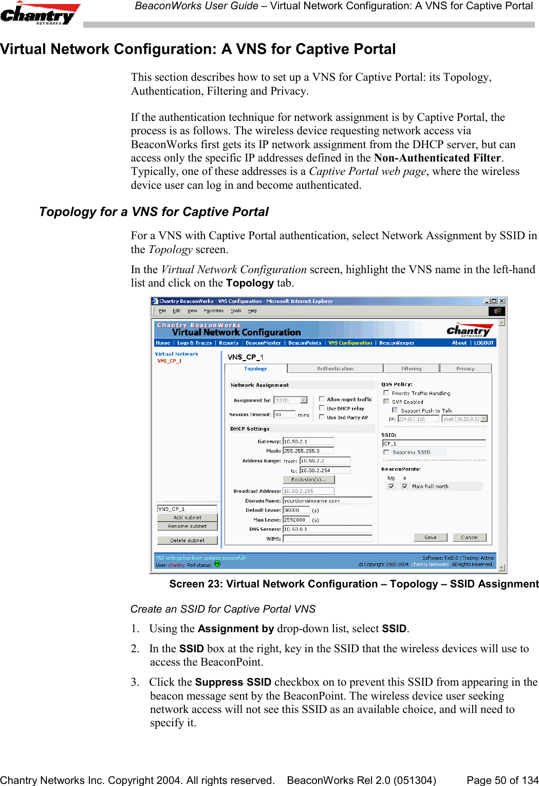
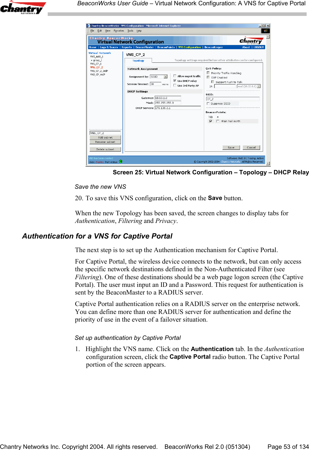
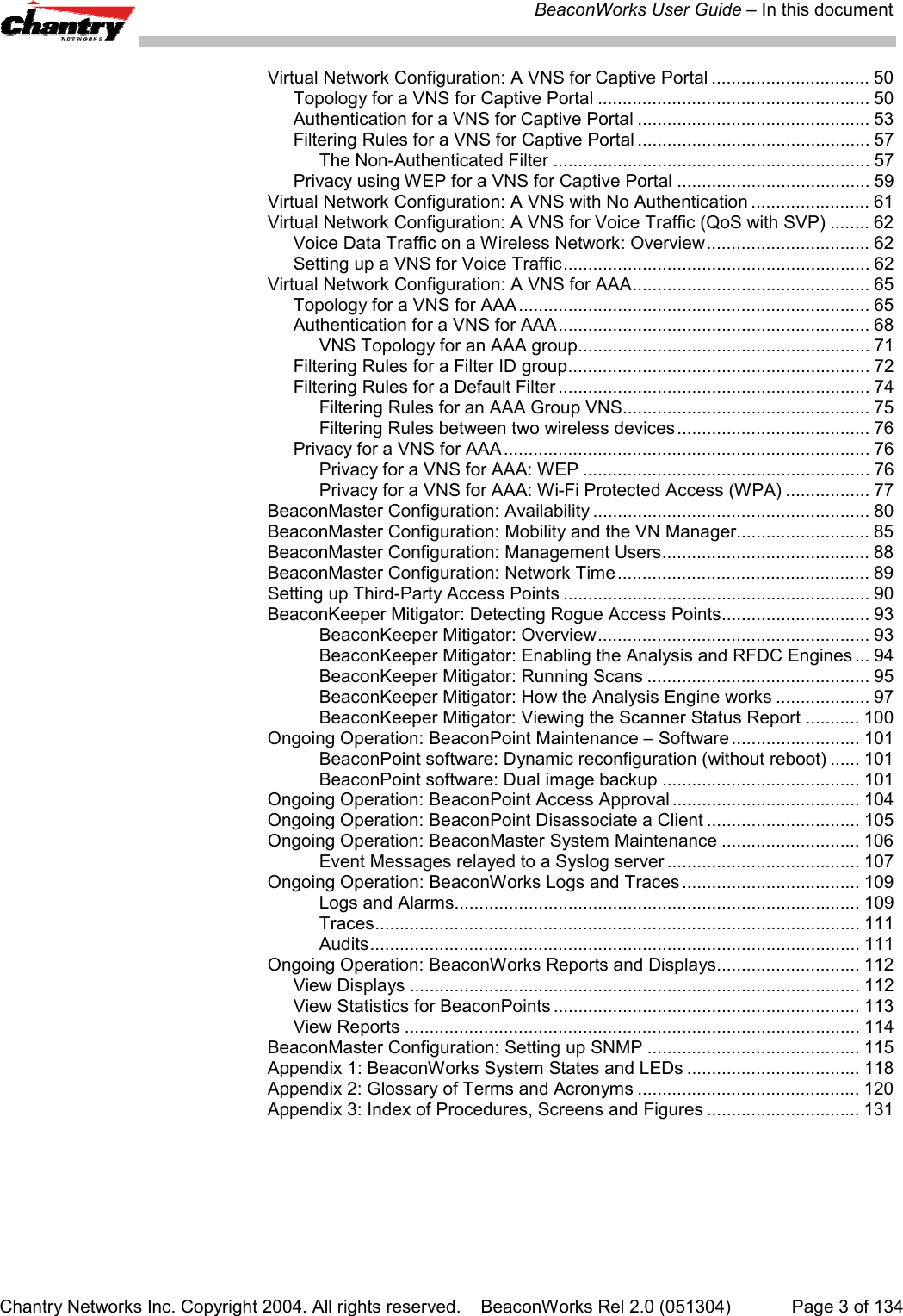
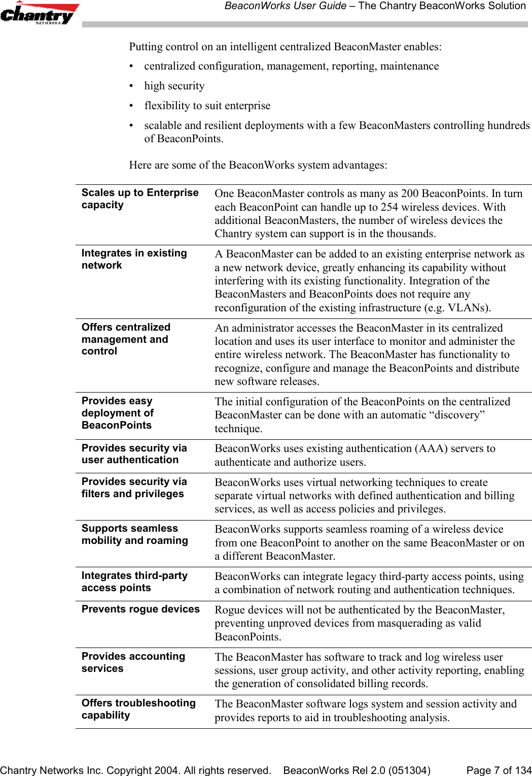
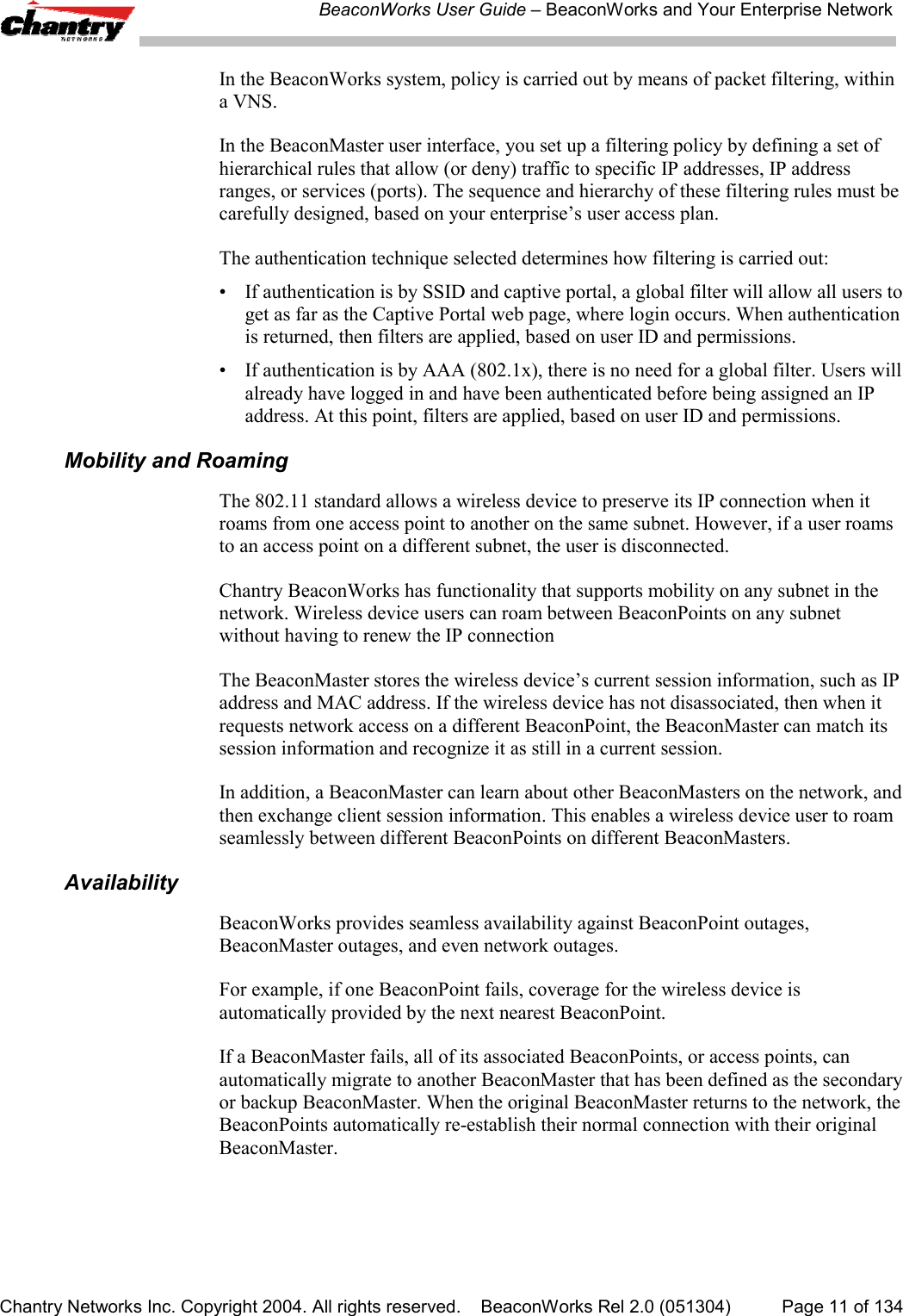
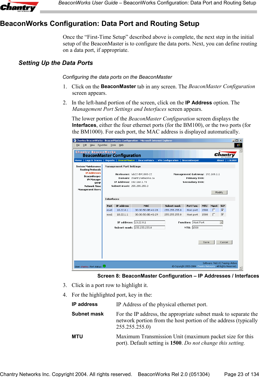
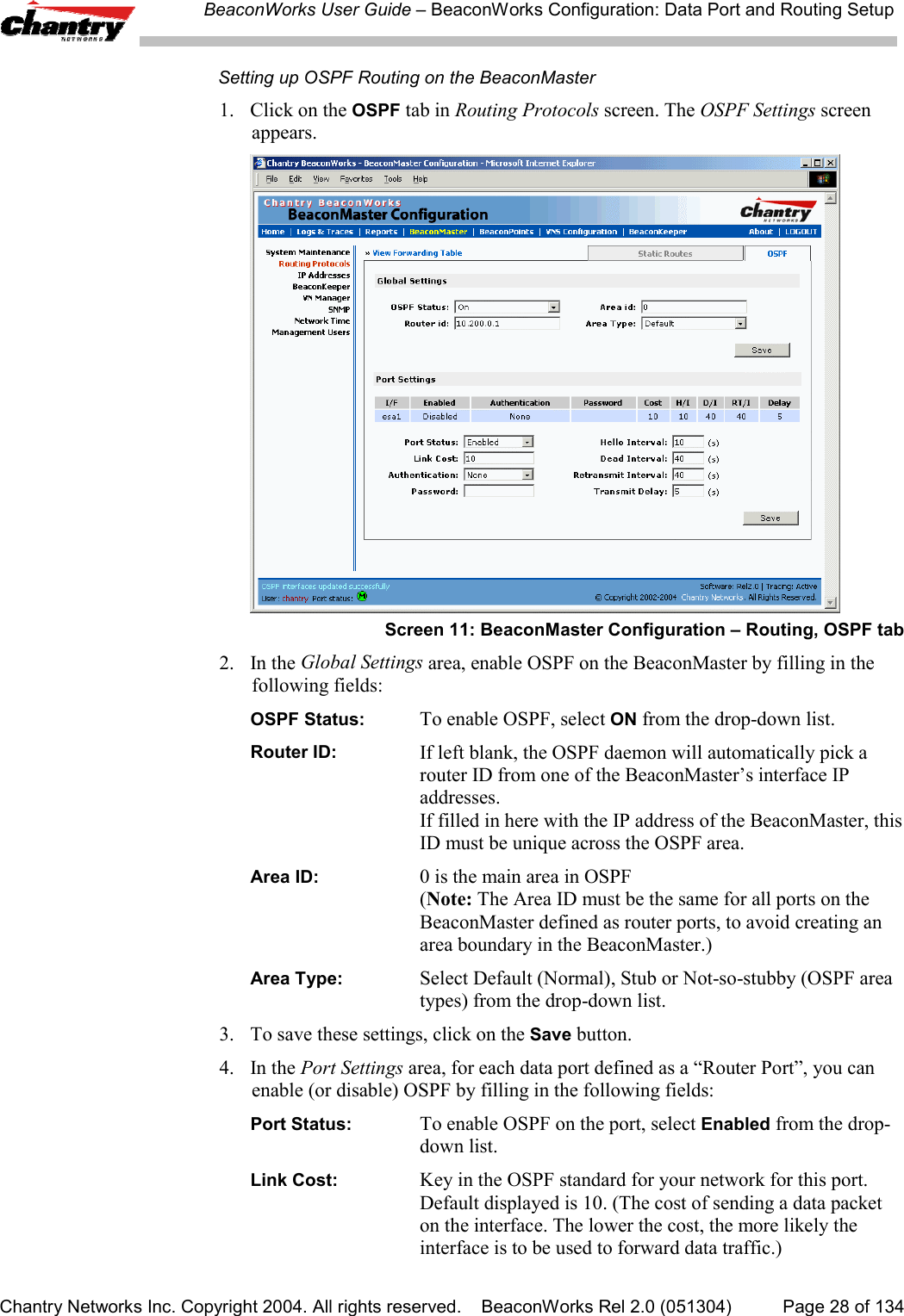
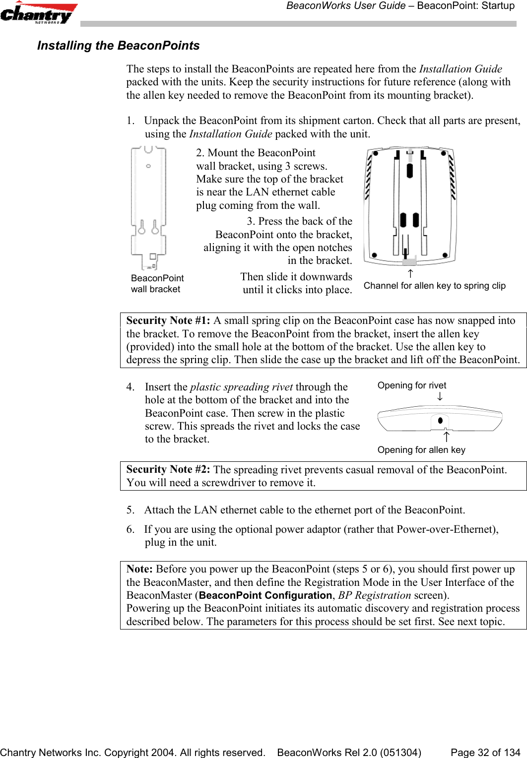
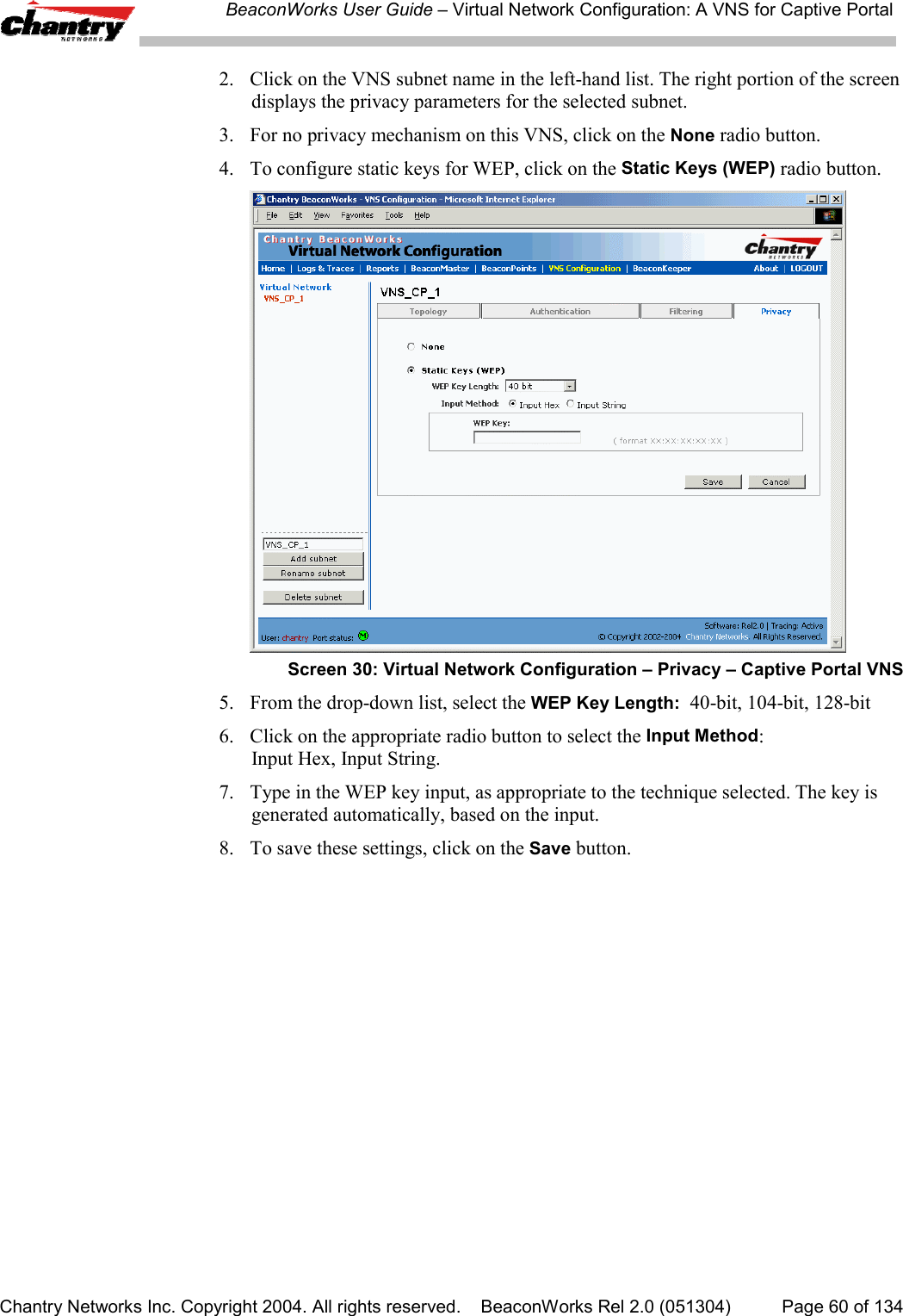
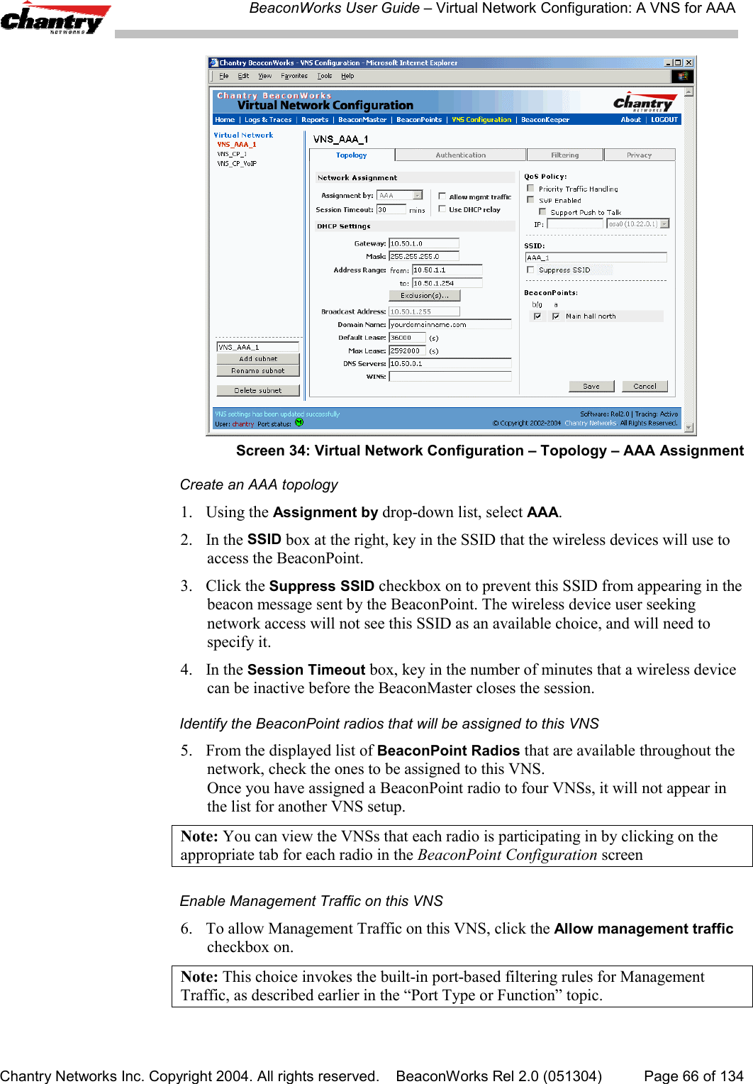
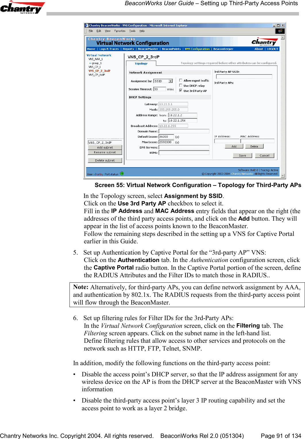
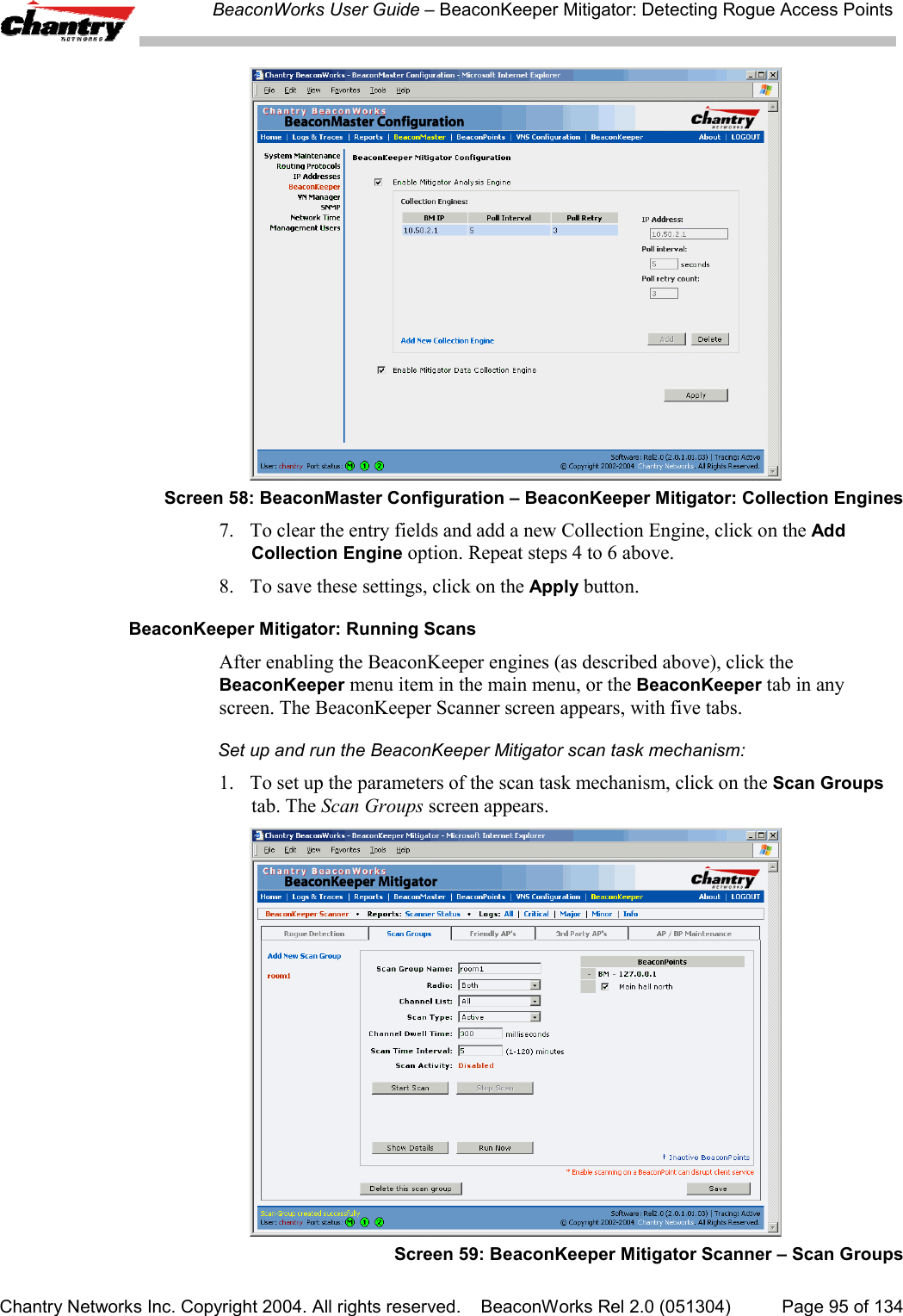
![BeaconWorks User Guide – Virtual Network Configuration: A VNS for Captive PortalChantry Networks Inc. Copyright 2004. All rights reserved. BeaconWorks Rel 2.0 (051304) Page 59 of 134Non-Authenticated Filters: ExamplesA basic Non-Authenticated Filter for Captive Portal should have three rules in thefollowing order:In Out Allow IP / Port Descriptionx x x IP address of the DefaultGatewayAllow all incoming wireless devices access to the default gateway ofthe VNS.xx x IP address of the DNSServerAllow all incoming wireless devices access to the DNS server of theVNS.x x *.*.*.* Deny everything else.Note: If you put URLs in the header and footer of the Captive Portal page, you mustinclude a filtering rule to allow traffic to each of these URLs. Put this rule above the“deny everything” rule.Here is another example of a Non-Authenticated Filter that adds two more filteringrules: one denies access to a specific IP address, and the next rule allows only HTMLtraffic, before denying all other access:In Out Allow IP / Port Descriptionx x x IP address of the DefaultGatewayAllow all incoming wireless devices access to the default gateway ofthe VNS.xx x IP address of the DNSServerAllow all incoming wireless devices access to the DNS server of theVNS.x x [a specific IP address, oraddress plus range]Deny all traffic to a specific IP address,or to a specific range within an IP address (such as :0/24)x x x *.*.*.*:80 Allow all port 80 (HTML) traffic.x x *.*.*.*. Deny everything else.Once a wireless device user has logged in on the Captive Portal page, and has beenauthenticated by the RADIUS server, then the following filters will apply:• Filter ID Filter, if a Filter ID associated with this user was returned theauthentication server• Default Filter, if no matching Filter ID was returned from the authentication server.These filters are described in detail in the Filtering for an AAA VNS.Privacy using WEP for a VNS for Captive PortalUse the Privacy screen to set up the static Wired Equivalent Privacy (WEP) keys for aselected VNS, so that it matches the WEP mechanism used on the rest of the network.In BeaconWorks Release 2.0, you can assign each radio on a BeaconPoint to up tofour VNSs by SSID. For each VNS, only one WEP key can be specified.BeaconWorks always uses the first key (key index 0).Set up a Static WEP key for a selected VNS1. In the Virtual Network Configuration screen, click on the Privacy tab. ThePrivacy screen appears.](https://usermanual.wiki/Chantry-Networks/BP200E.USERS-MANUAL-1/User-Guide-474549-Page-59.png)
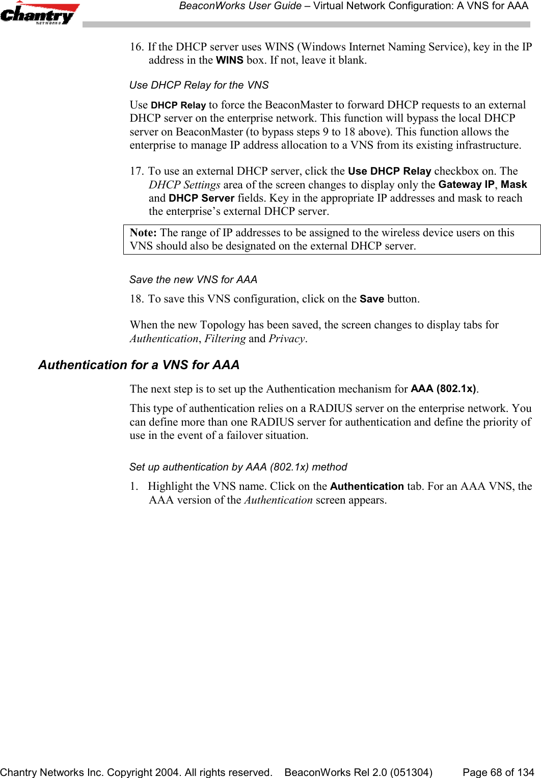
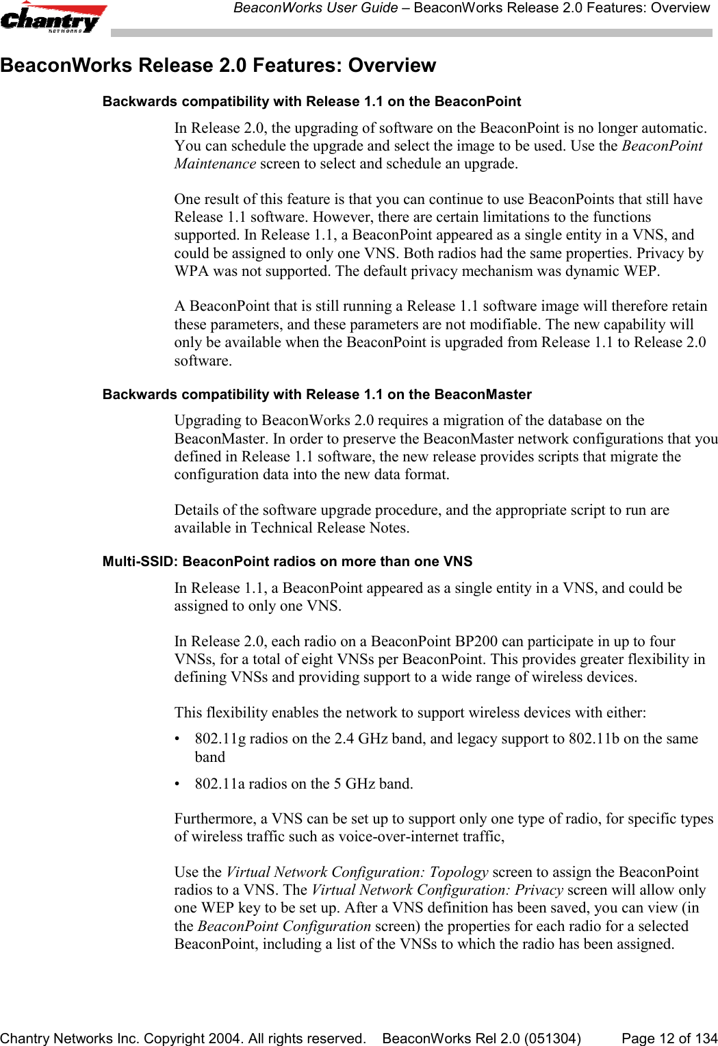
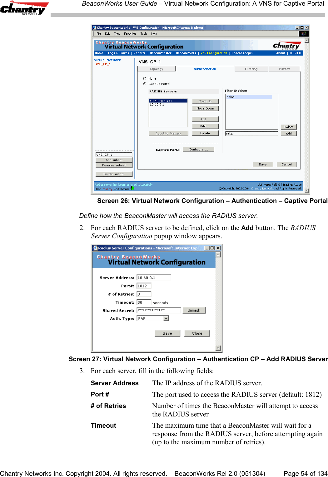
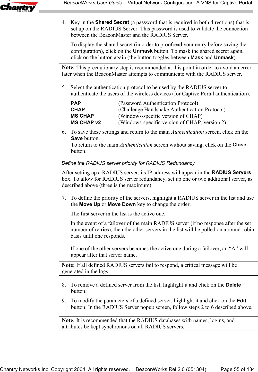
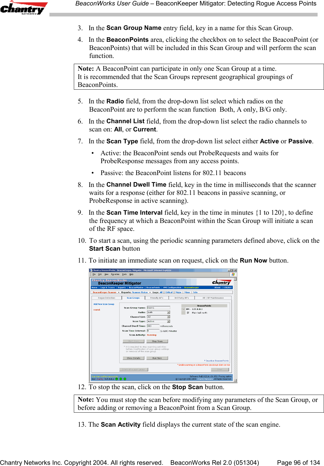
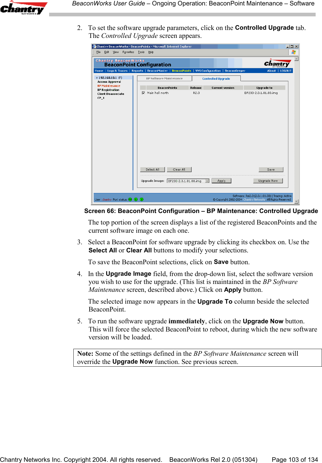
![BeaconWorks User Guide – Virtual Network Configuration: A VNS for AAAChantry Networks Inc. Copyright 2004. All rights reserved. BeaconWorks Rel 2.0 (051304) Page 70 of 1344. Key in the Shared Secret (a password that is required in both directions) that isset up on the RADIUS Server. This password is used to validate the connectionbetween the BeaconMaster and the RADIUS Server.To display the shared secret (in order to proofread your entry before saving theconfiguration), click on the Unmask button. To mask the shared secret again,click on the button again (the button toggles between Mask and Unmask).Note: This precautionary step is recommended at this point in order to avoid an errorlater when the BeaconMaster attempts to communicate with the RADIUS server.5. In the NAS Identifier field, type in the Network Access Server (NAS) identifier, aRADIUS attribute that identifies the server responsible for passing information todesignated RADIUS Servers and then acting on the response returned. [Optional]6. To save these settings and return to the main Authentication screen, click on theSave button. To return to the main Authentication screen without saving, click onthe Close button.Define the RADIUS server priority for RADIUS RedundancyAfter setting up a RADIUS server, its IP address appears in the RADIUS Servers box.To allow for RADIUS server redundancy, set up a second server, as described above.7. To define the priority of the servers, highlight a RADIUS server in the list and usethe Move Up or Move Down key to change the order.The first server in the list is the active one.In the event of a failover of the main RADIUS server (if no response after the setnumber of retries), then the other servers in the list will be polled on a round-robinbasis until one responds.If one of the other servers becomes the active one during a failover, an “A” willappear after that server name.Note: If all defined RADIUS servers fail to respond, a critical message will begenerated in the logs.8. To remove a defined server from the list, highlight it and click on the Deletebutton.9. To modify the parameters of a defined server, highlight it and click on the Editbutton. In the RADIUS Server popup screen, follow steps 2 to 6 described above.Note: It is recommended that the RADIUS databases with names, logins, andattributes be kept synchronous on all RADIUS servers.Define the Filter ID Values on this VNS.10. In the Filter ID Values entry field, key in the name of a group that you want todefine specific filtering rules for, to control network access. Click on the Addbutton. The Filter ID name appears in the list above.Repeat for additional Filter ID names.These Filter ID names will appear in the Filter ID list in the Filtering screen.](https://usermanual.wiki/Chantry-Networks/BP200E.USERS-MANUAL-1/User-Guide-474549-Page-70.png)
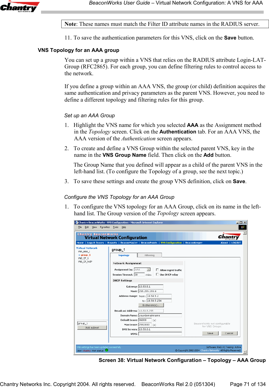
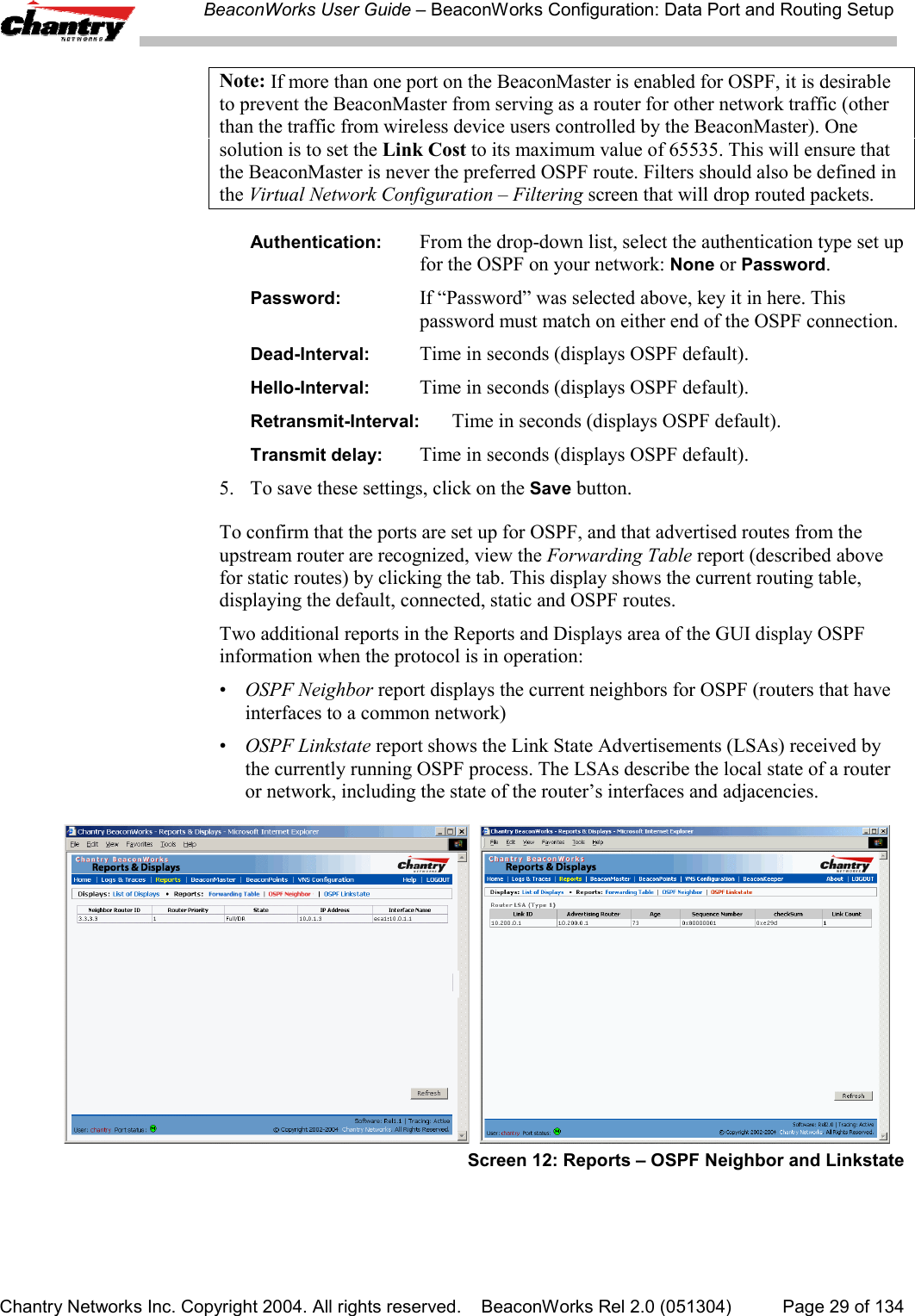
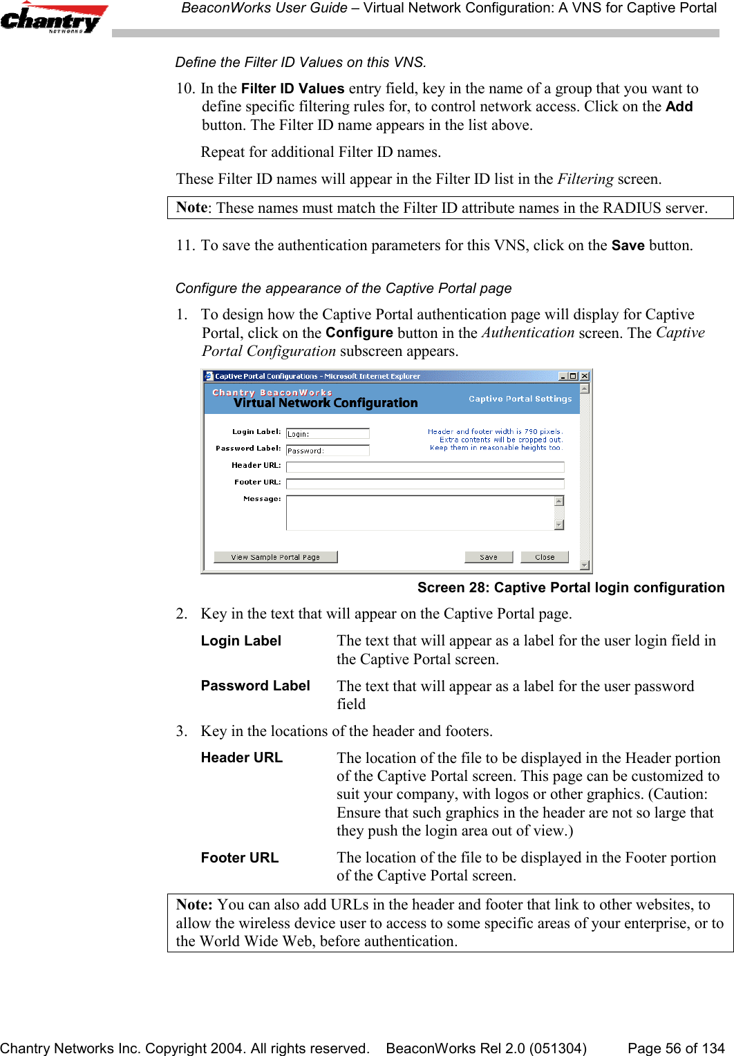
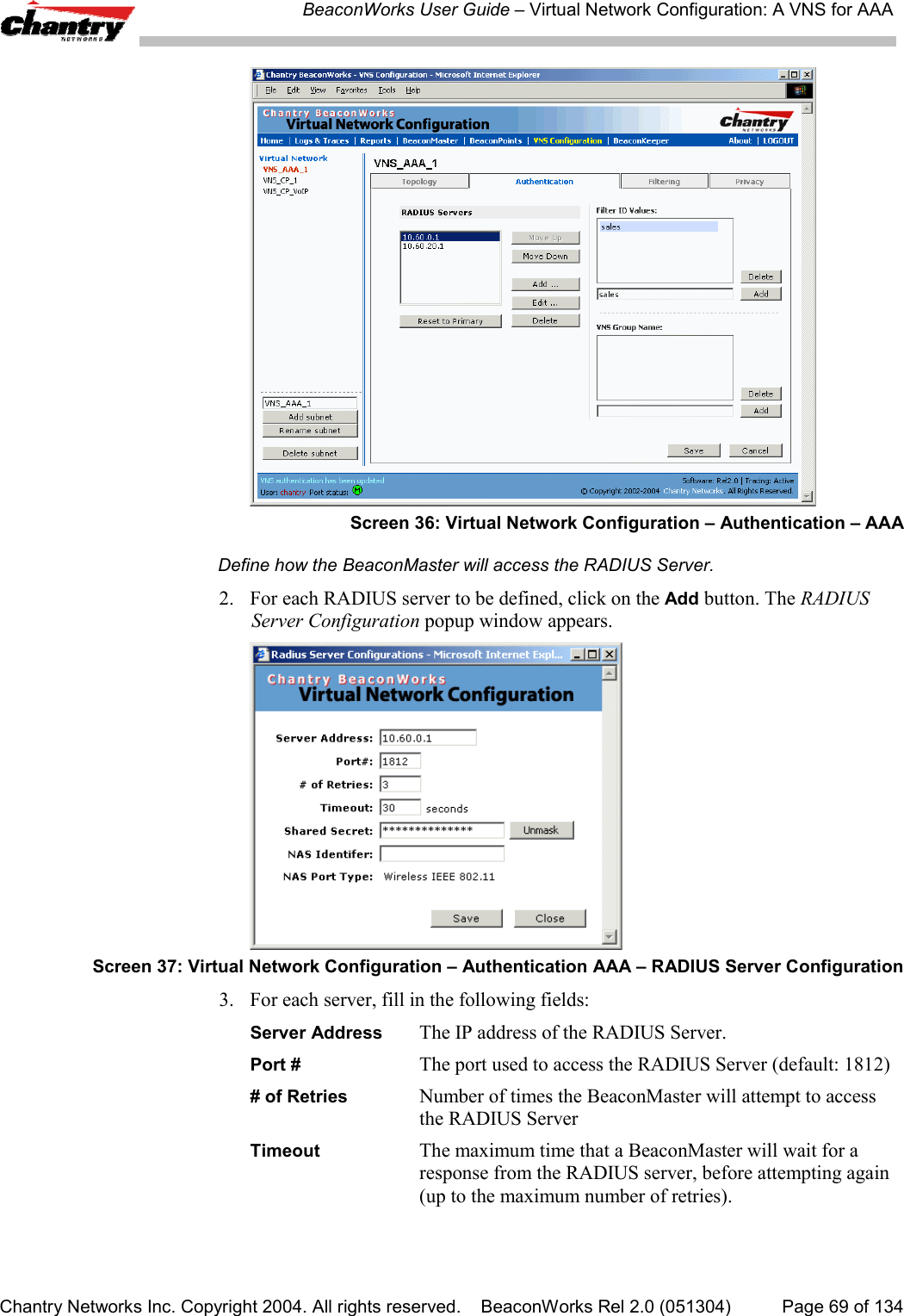
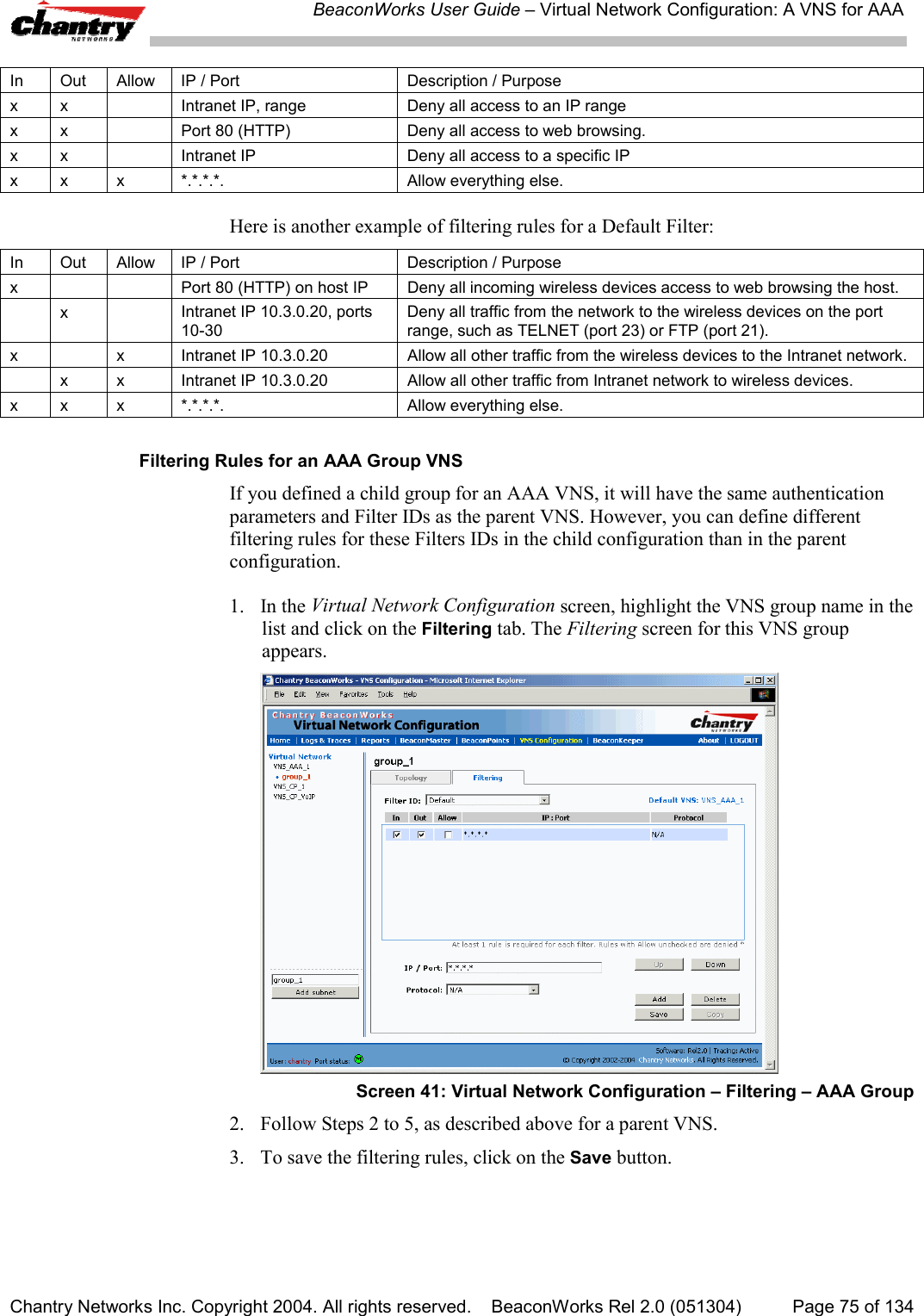
![BeaconWorks User Guide – Virtual Network Configuration: A VNS for AAAChantry Networks Inc. Copyright 2004. All rights reserved. BeaconWorks Rel 2.0 (051304) Page 72 of 1342. Define the DHCP settings for this VNS, as described above for the parent VNS.The Gateway and DHCP Ranges must be different than those of the parent VNS.3. To save the modifications, click on Save.The filtering screen for an AAA Group is described at the end of the Filtering topic.Filtering Rules for a Filter ID groupAfter setting up RADIUS parameters for Authentication and the Filter ID Values, thenext step is to define the filtering rules for the Filter ID Values on the VNS for AAA.When the wireless device user enters a login identification, that identification is sentby the BeaconMaster to the RADIUS server or other authentication server, through asequence of exchanges depending on the type of authentication protocol used.When the server allows this request for authentication (sends an “access-accept”message), the RADIUS server may also send back to the BeaconMaster a Filter IDattribute associated with the user, or a Login-LAT-Group identifier for the user.If the Filter ID attribute (or Login-LAT-Group attribute) from the RADIUS servermatches a Filter ID Value that you have set up on the BeaconMaster, theBeaconMaster applies to the wireless device user the filtering rules that you definedfor that Filter ID Value.Note: The BeaconMaster’s Filter ID Values must match the Filter ID attribute namesin the RADIUS server.If no Filter ID is returned by the authentication server, or no match is found on theBeaconMaster, then the Default Filter and its filtering rules will apply to the wirelessdevice user.Define filtering rules for a Filter ID group1. In the Virtual Network Configuration screen, highlight the VNS name in the listand click on the Filtering tab. The Filtering screen for this VNS appears.2. Using the Filter ID drop-down list, select one of the names you defined in theFilter ID Values field in the Authentication screen [one of your enterprise’s usergroups, such as Sales, Engineering, Teacher, Guest....]](https://usermanual.wiki/Chantry-Networks/BP200E.USERS-MANUAL-1/User-Guide-474549-Page-72.png)
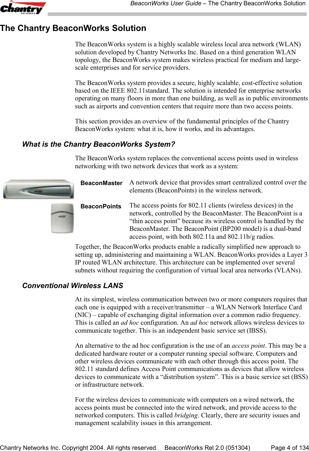
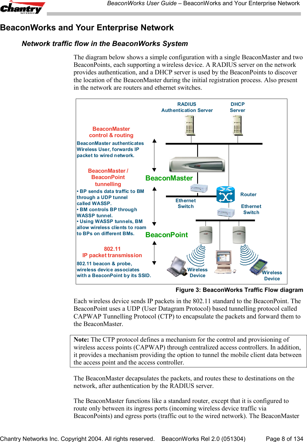
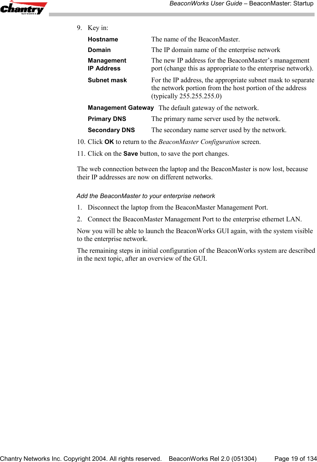
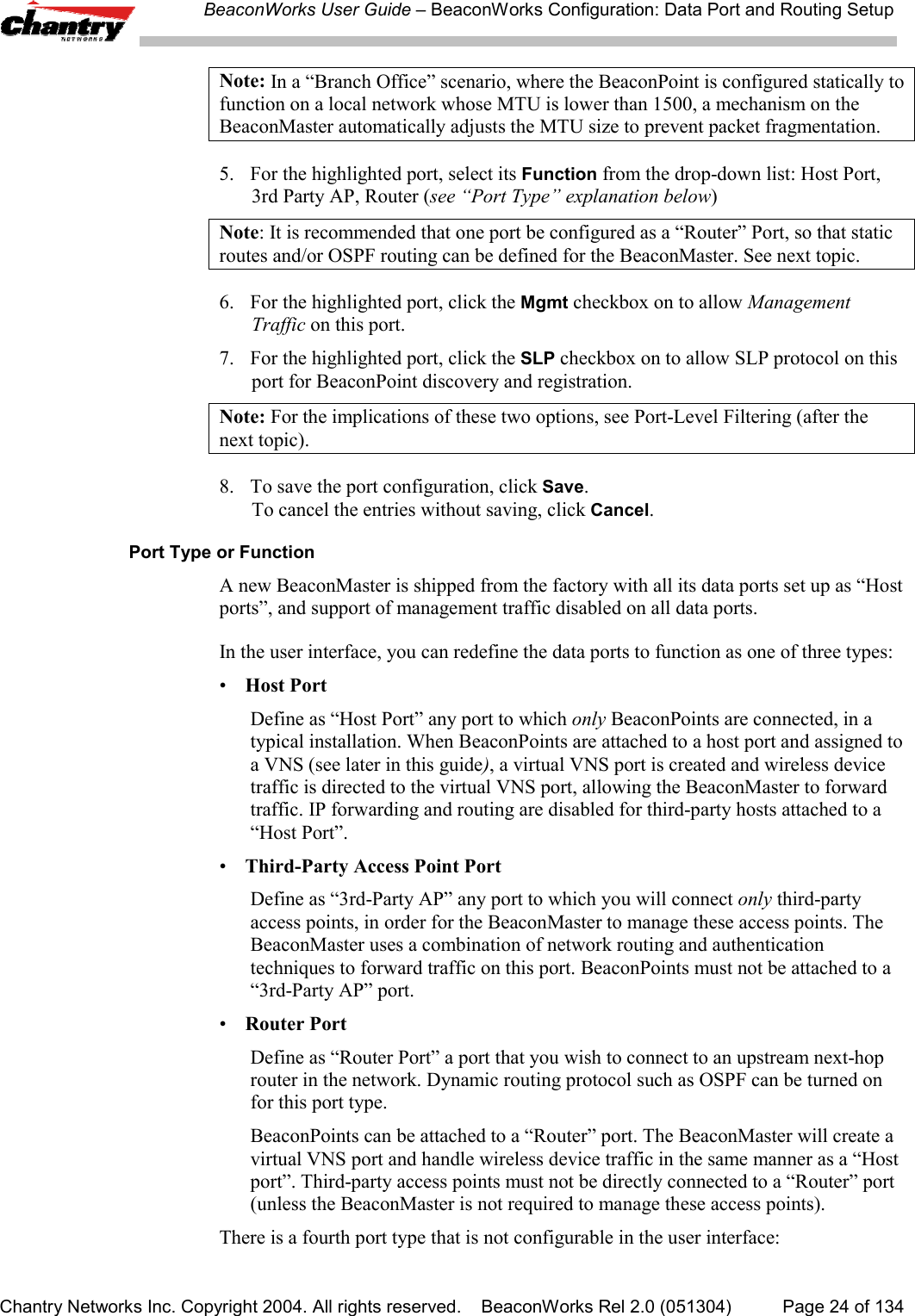
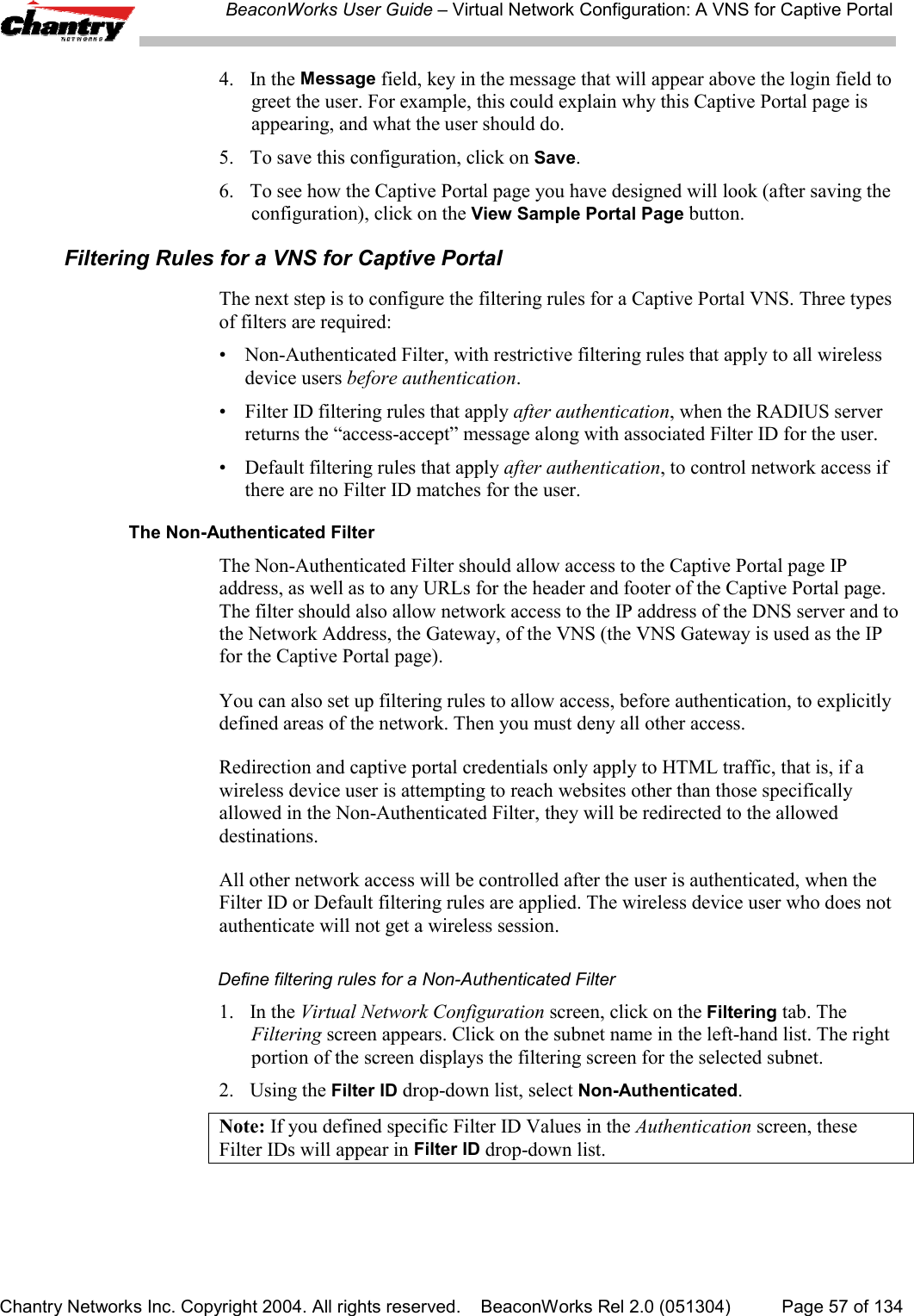
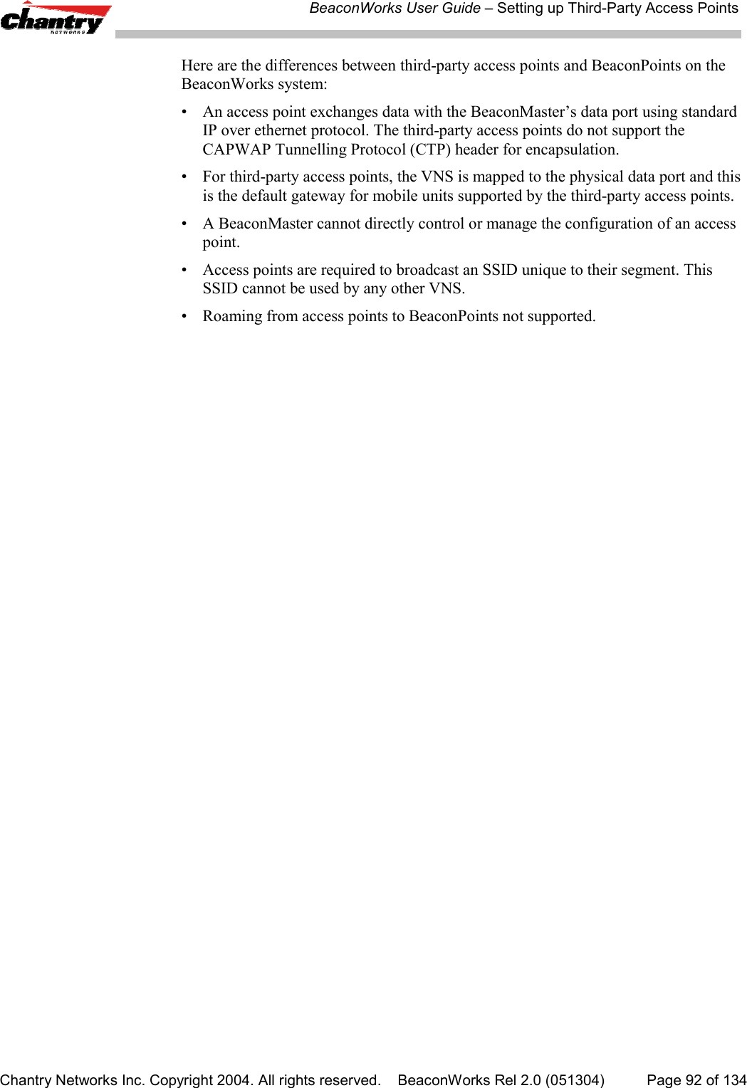
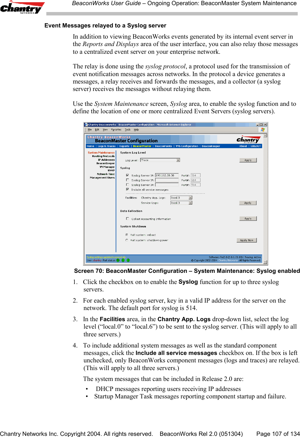
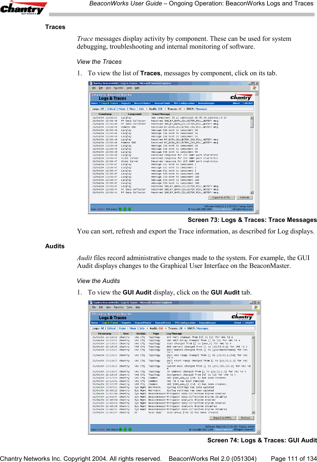
![BeaconWorks User Guide – Virtual Network Configuration: A VNS for AAAChantry Networks Inc. Copyright 2004. All rights reserved. BeaconWorks Rel 2.0 (051304) Page 74 of 134In Out Allow IP / Port Descriptionx x *.*.*.*:22-23 Deny all telnet sessionsx x [specific IP address, range] Deny all traffic to a specific IP address, or address rangex x x *.*.*.*. Allow everything else.The second example does the opposite of the first example. It allows only somespecific access and denies everything else.In Out Allow IP / Port Descriptionx x x [specific IP address, range] Allow all traffic to a specific IP address, or address rangex x *.*.*.*. Deny everything else.Filtering Rules for a Default FilterIf, after authentication of the wireless device user, no Filter ID attribute is returned bythe authentication server for this user, or no match is found on the BeaconMaster for aFilter ID Value, then the Default Filter will apply.Define the filtering rules for a Default Filter1. In the Virtual Network Configuration – Filtering screen, using the Filter ID drop-down list, select Default.Screen 40: Virtual Network Configuration – Default Filter2. Follow Steps 2 to 5, as described above.3. To save the filtering rules, click on the Save button.Default Filter: ExamplesHere is an example of filtering rules for a Default Filter:](https://usermanual.wiki/Chantry-Networks/BP200E.USERS-MANUAL-1/User-Guide-474549-Page-74.png)
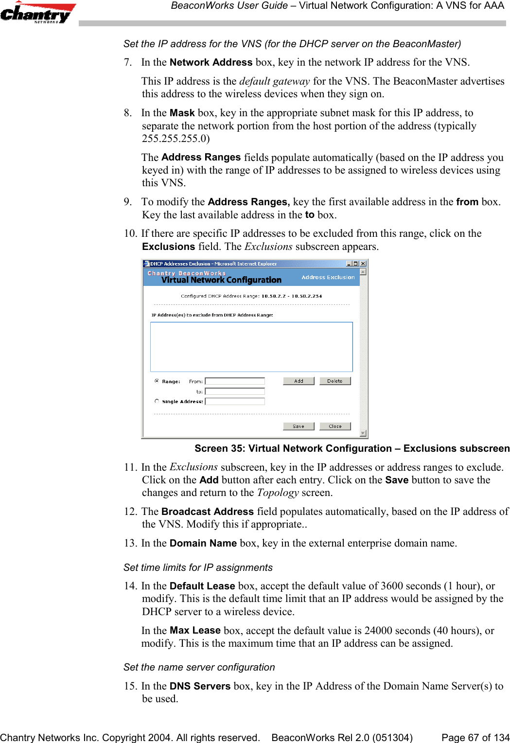
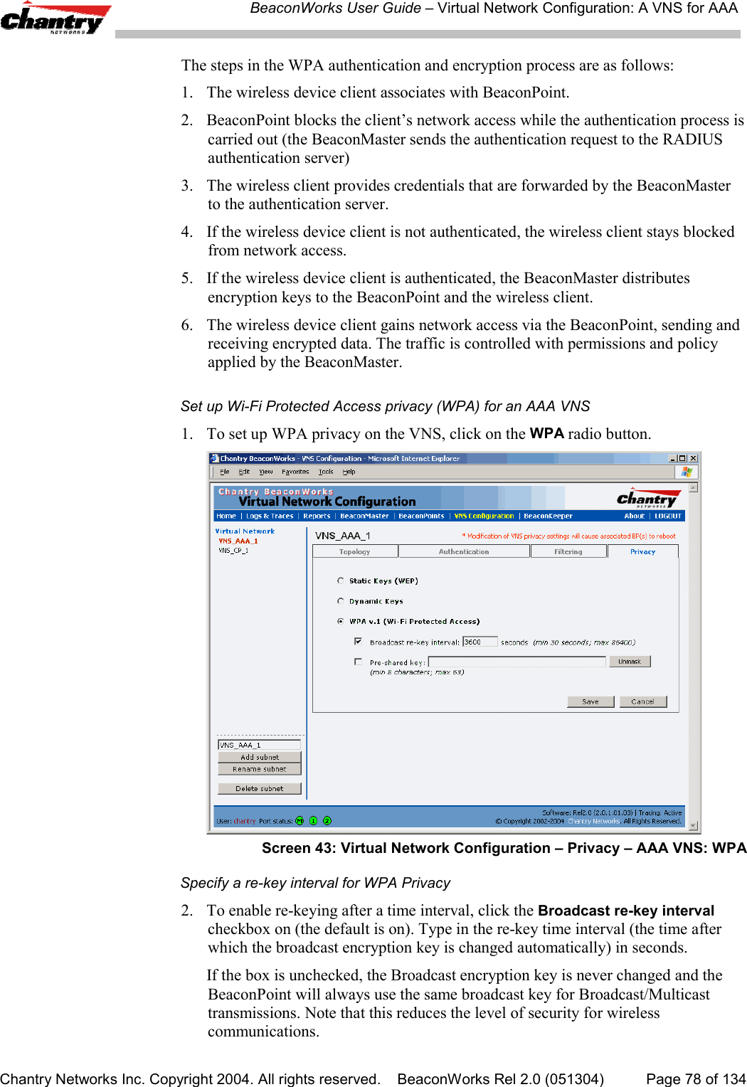
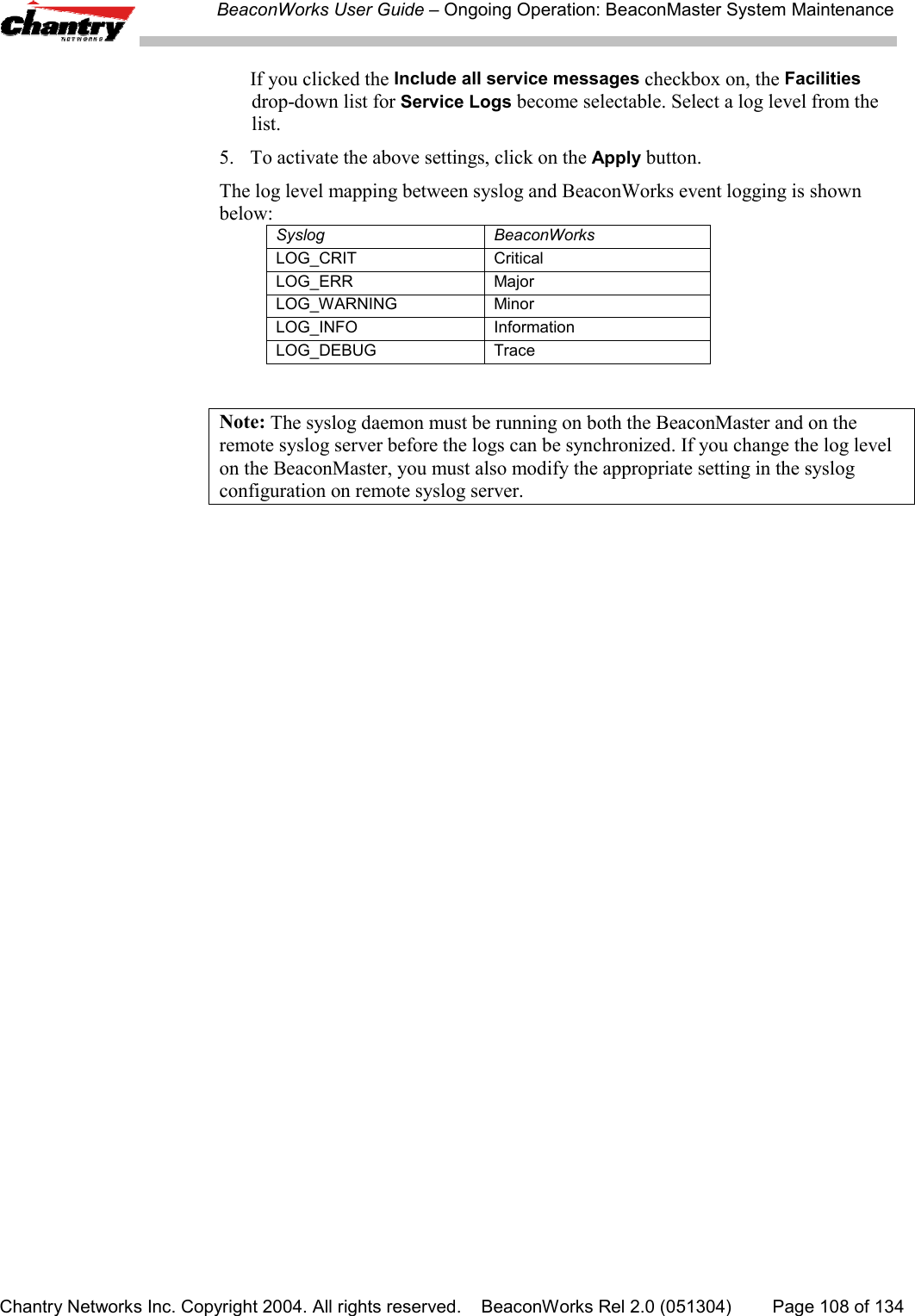
![BeaconWorks User Guide – Virtual Network Configuration: A VNS for AAAChantry Networks Inc. Copyright 2004. All rights reserved. BeaconWorks Rel 2.0 (051304) Page 76 of 134Filtering Rules between two wireless devicesTraffic from two wireless devices that are on the same VNS and are connected to thesame BeaconPoint will pass through the BeaconMaster and therefore be subject tofiltering policy.You can set up filtering rules that allow each wireless device access to the defaultgateway, but prevent each device from communicating each other. Add the followingtwo rules to a Filter ID filter before allowing everything else:In Out Allow IP / Port Description / Purposex x x [Intranet IP] Allow access to the Gateway IP address of the VNS onlyx x [Intranet IP, range] Deny all access to the VNS subnet range 0/24x x x *.*.*.*. Allow everything else.Privacy for a VNS for AAAUse the Privacy screen to set up privacy mechanisms for a VNS with authenticationby 802.1x (AAA). There are three options• Static keys (WEP)• Dynamic keys• Wi-Fi Protected Access (WPA) version 1, with Temporal Key Integrity Protocol(TKIP).Privacy for a VNS for AAA: WEPSet up static WEP privacy for a selected AAA VNS1. In the Virtual Network Configuration screen, highlight the VNS name in the listand click on the Privacy tab. The Privacy screen for the selected VNS appears.Screen 42: Virtual Network Configuration – Privacy – AAA VNS: Static Keys](https://usermanual.wiki/Chantry-Networks/BP200E.USERS-MANUAL-1/User-Guide-474549-Page-76.png)
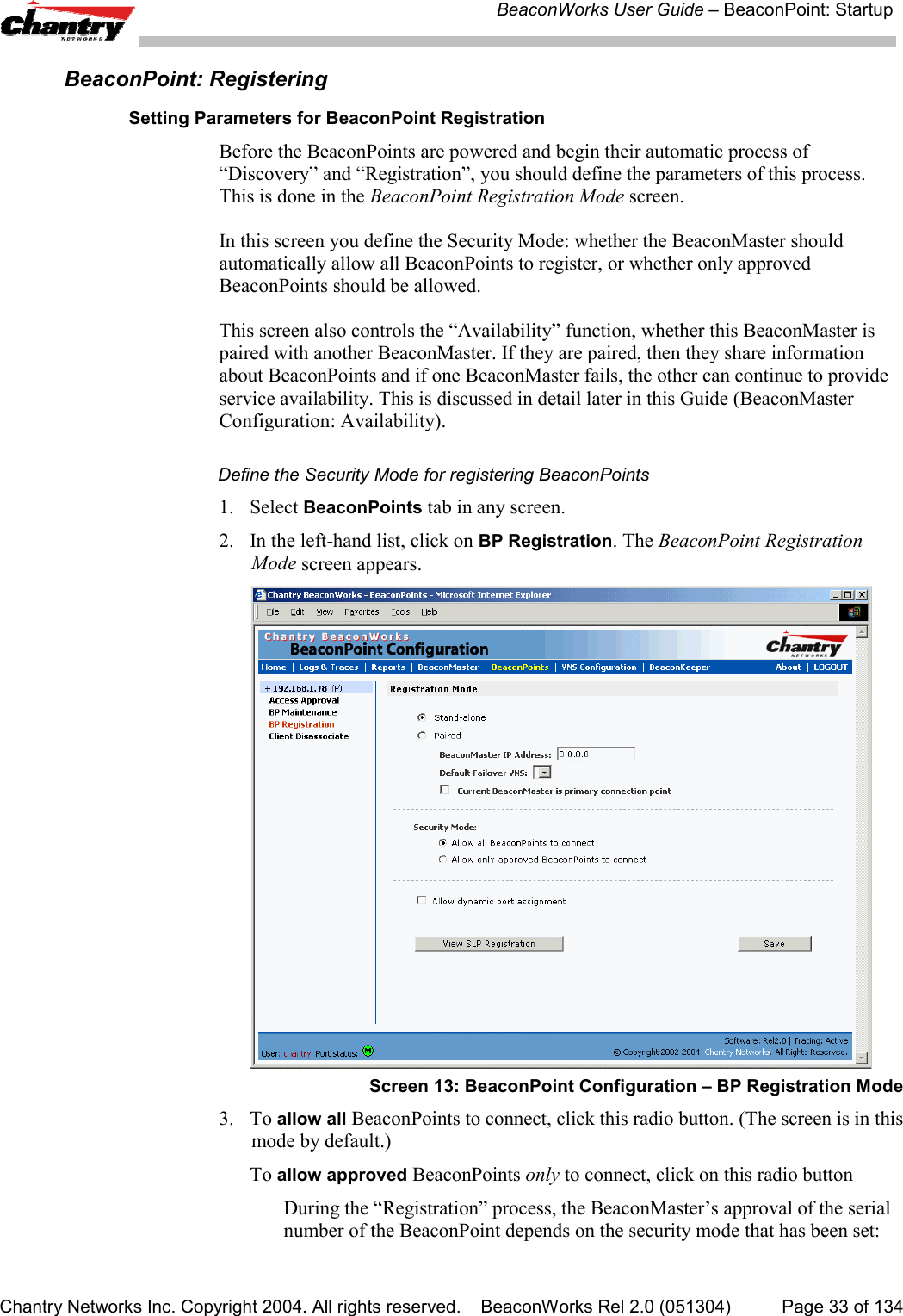
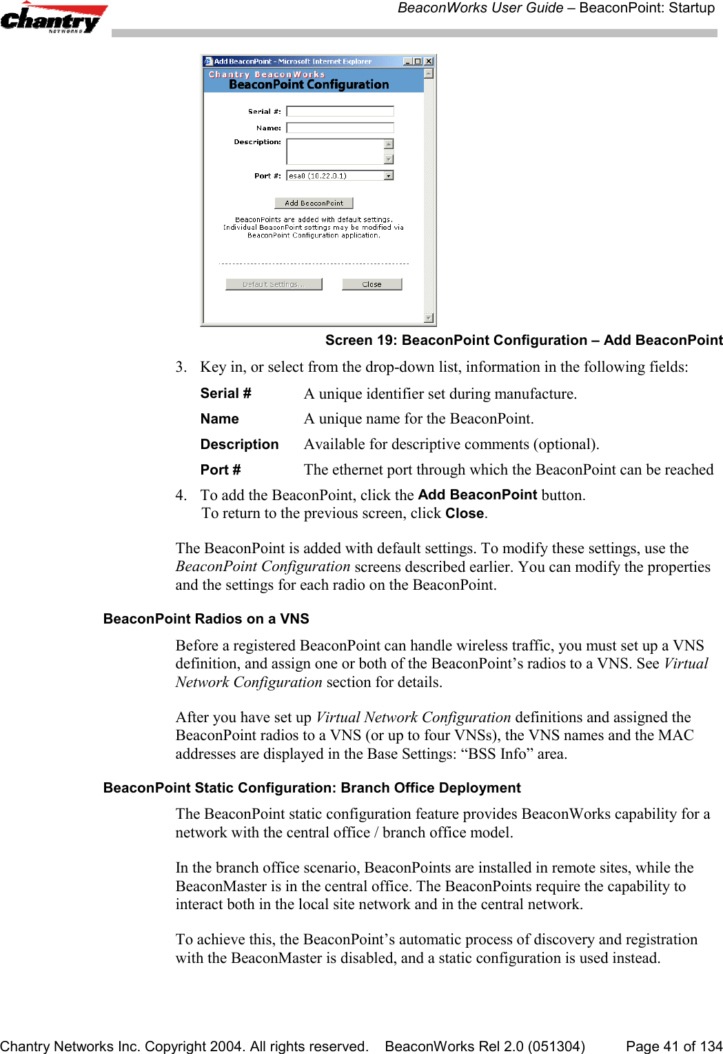
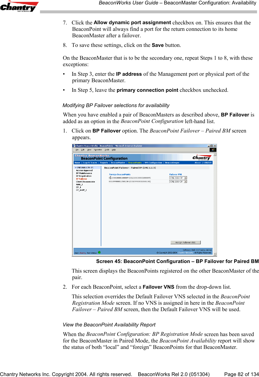
![BeaconWorks User Guide – BeaconMaster Configuration: AvailabilityChantry Networks Inc. Copyright 2004. All rights reserved. BeaconWorks Rel 2.0 (051304) Page 81 of 134A second method to set up the BeaconMasters is as follows:1. In the BP Registration screen, enable the two BeaconMasters as a pair, asdescribed below.2. Add each BeaconPoint manually to each BeaconMaster. (Select the BeaconPointtab. In the BeaconPoint Properties screen, click on the Add BeaconPoint button.The BeaconPoint Configuration subscreen appears. Define the BeaconPoint andclick on the Add BeaconPoint button.)Note: Caution: If two Beacon Masters are paired and one BeaconMaster has the“Allow All” option set for BeaconPoint registration, all BeaconPoints will registerwith that BeaconMaster.Set up two BeaconMasters as a pair, for availability1. On the BeaconMaster that is to be the primary, select BeaconPoints tab in anyscreen. Then, in the left-hand list, click on BP Registration. The BeaconPointRegistration Mode screen appears.Screen 44: BeaconPoint Configuration – Paired BeaconMasters for Availability2. Click the Paired radio button.3. Enter the IP address of the physical port of the secondary BeaconMaster.Note: This IP must be on a routable subnet between the two BeaconMasters.4. Select a Default Failover VNS on the other BeaconMaster from the drop-downlist of VNS’s (this list will be populated only after a VNS has been defined).5. Since this BeaconMaster is to be the primary connection point, click thecheckbox on.6. Set the Security Mode to “Allow Approved” by clicking the radio button.[recommended after initial set up for paired BeaconMasters]](https://usermanual.wiki/Chantry-Networks/BP200E.USERS-MANUAL-1/User-Guide-474549-Page-81.png)
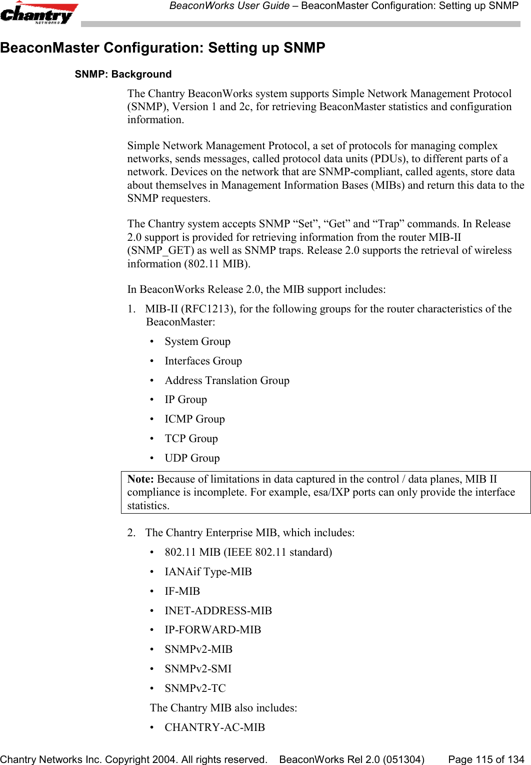
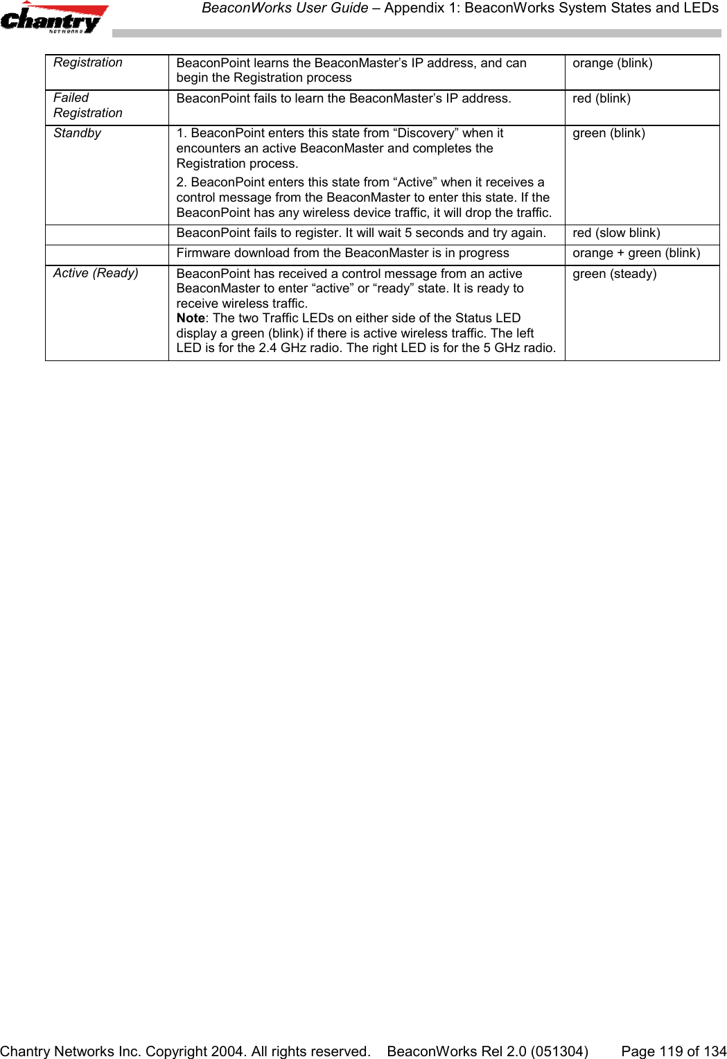
![BeaconWorks User Guide – BeaconMaster Configuration: Setting up SNMPChantry Networks Inc. Copyright 2004. All rights reserved. BeaconWorks Rel 2.0 (051304) Page 117 of 1343. Key in:Contact Name The name of SNMP administrator.Location Location of the SNMP administration machine(descriptive).Read Community Key in the password for Read activity.NameRead/Write Key in the password for Read/Write activity.Community NameSNMP Port: Key in the destination port for SNMP traps. The industrystandard is 162.[If left blank, no traps are generated.]Forward Traps From the drop-down list, select the severity level of thetraps to be forwarded: Informational, Minor, Major,Critical.Manager A: The IP address of the specific machine on the networkwhere the SNMP traps are monitored.Manager B: The IP address of a second specific machine on thenetwork where the SNMP traps are monitored, if ManagerA is not available.To enable SNMP traps, ensure that the following three fields are defined:• SNMP port• Read Community• Manager A and/or Manager BThe list of SNMP traps supported can be found in the Chantry MIB.](https://usermanual.wiki/Chantry-Networks/BP200E.USERS-MANUAL-1/User-Guide-474549-Page-117.png)
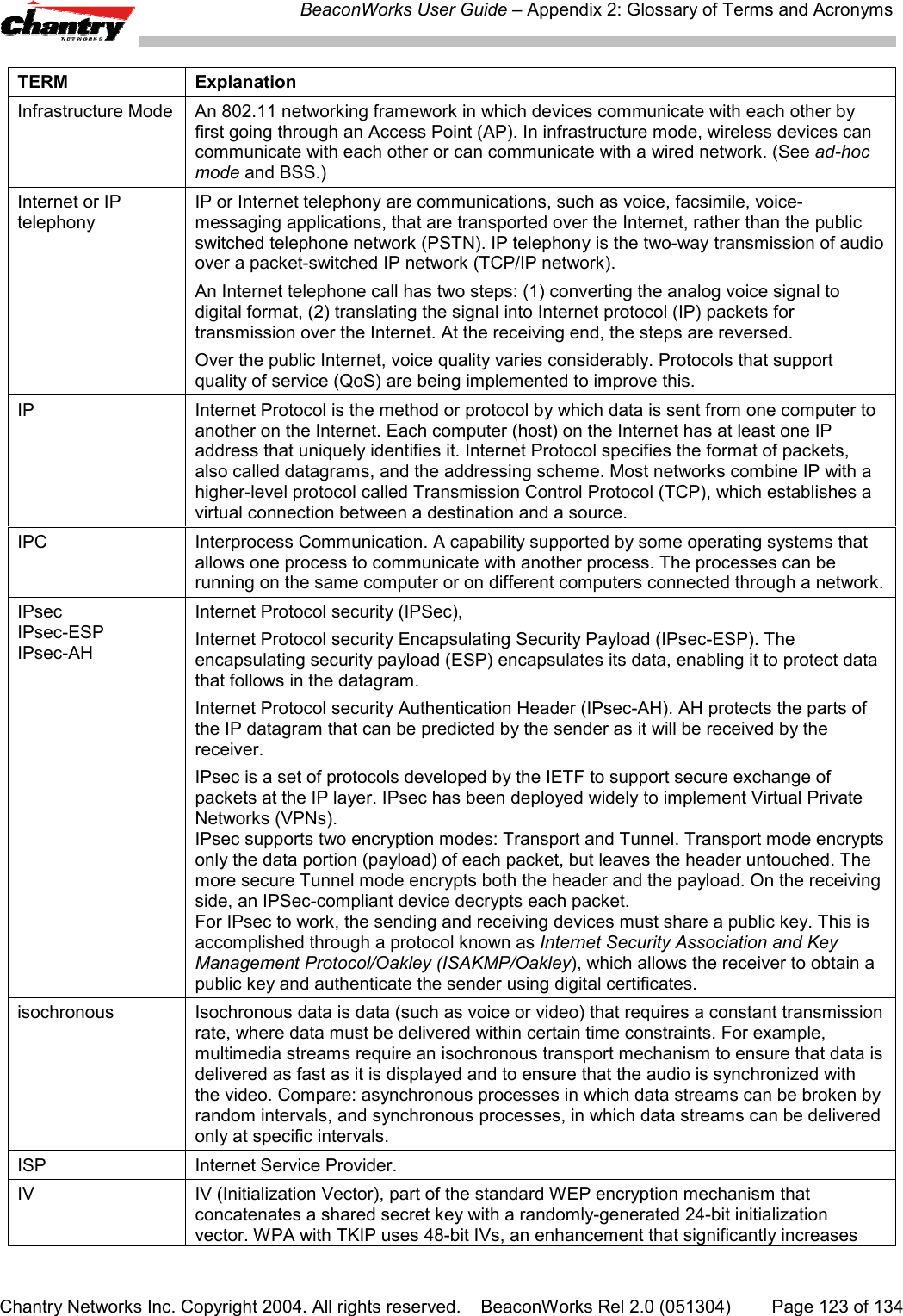
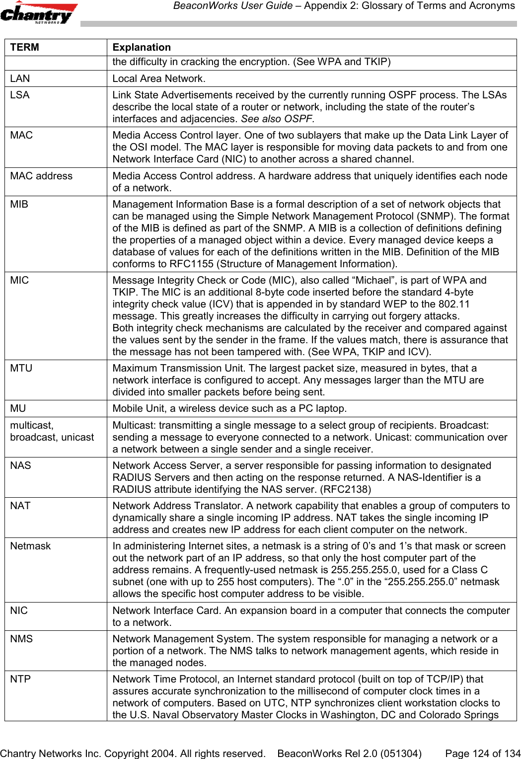
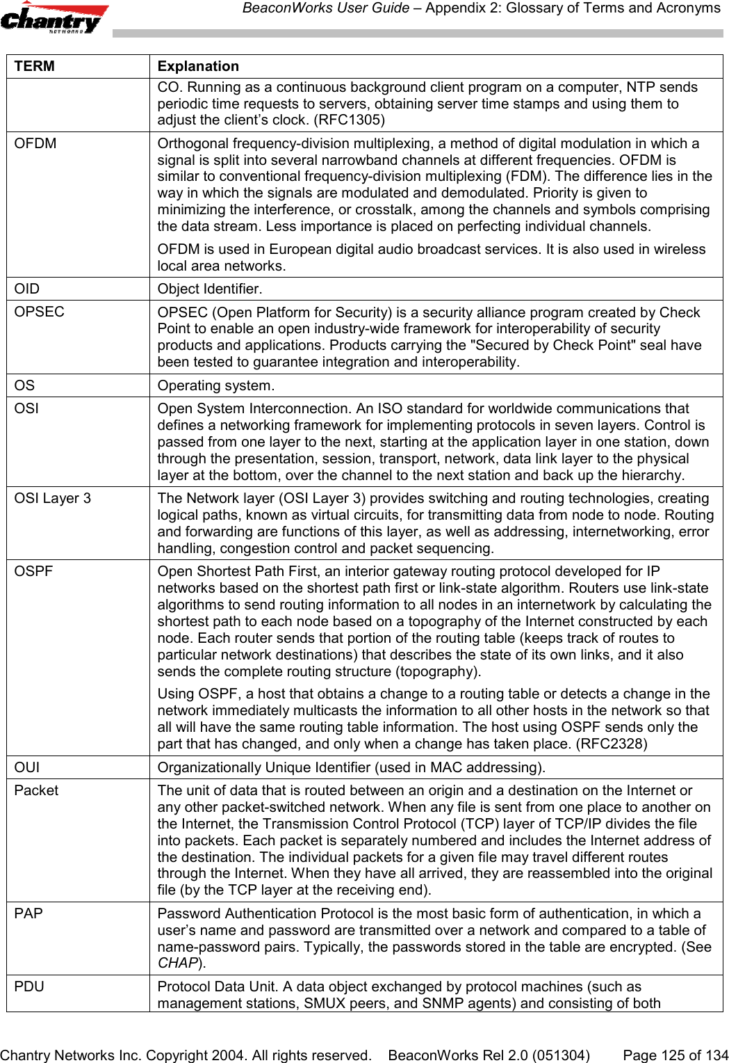
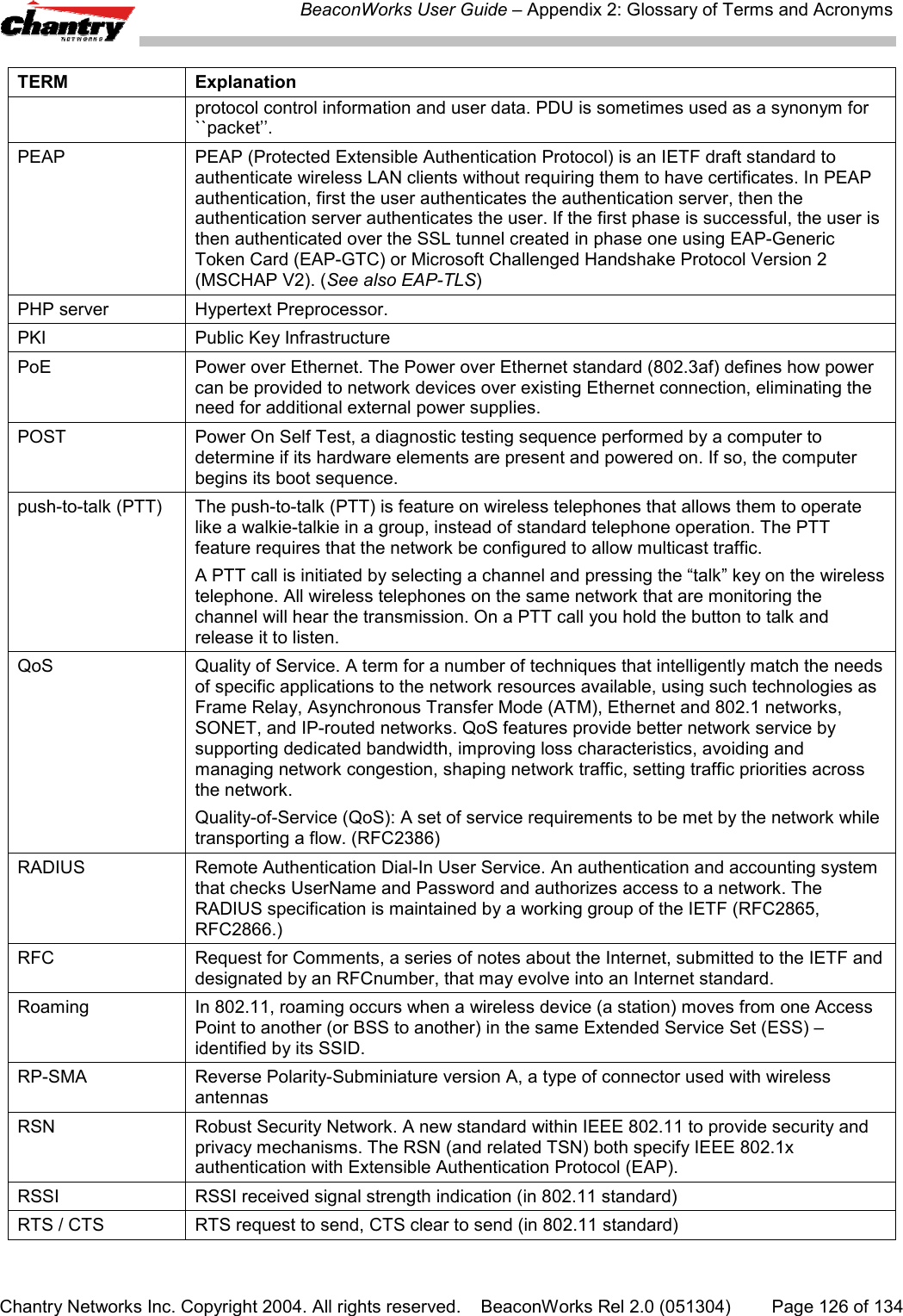
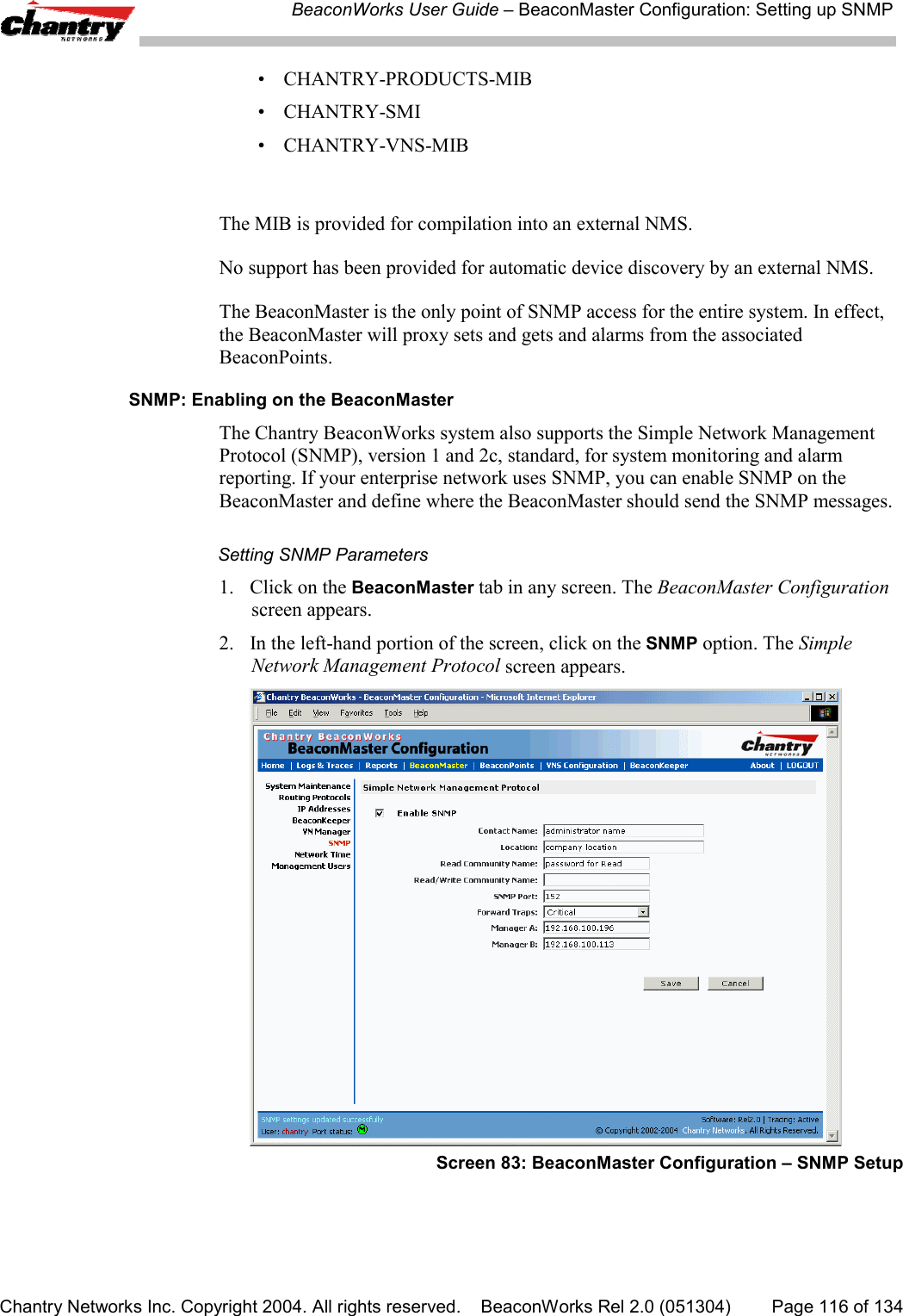
![BeaconWorks User Guide – Appendix 2: Glossary of Terms and AcronymsChantry Networks Inc. Copyright 2004. All rights reserved. BeaconWorks Rel 2.0 (051304) Page 122 of 134TERM Explanationfrequency to frequency as a function of time over a wide band of frequencies. Thistechnique reduces interference. If synchronized properly, a single logical channel ismaintained. (Compare DSSS)FQDN Fully Qualified Domain Name. A “friendly” designation of a computer, of the generalform computer.[subnetwork.].organization.domain. The FQDN names must betranslated into an IP address in order for the resource to be found on a network,usually performed by a Domain Name Server.FTM Forwarding Table Manager.FTP File Transfer Protocol.Gateway In the wireless world, an access point with additional software capabilities such asproviding NAT and DHCP. Gateways may also provide VPN support, roaming,firewalls, various levels of security, etc.Gigabit Ethernet The high data rate of the Ethernet standard, supporting data rates of 1 gigabit (1,000megabits) per second.GUI Graphical User InterfaceHeartbeat message A heartbeat message is a UDP data packet used to monitor a data connection, pollingto see if the connection is still alive.In general terms, a heartbeat is a signal emitted at regular intervals by software todemonstrate that it is still alive. In networking, a heartbeat is the signal emitted by aLevel 2 Ethernet transceiver at the end of every packet to show that the collision-detection circuit is still connected.Host (1) A computer (usually containing data) that is accessed by a user working on aremote terminal, connected by modems and telephone lines.(2) A computer that is connected to a TCP/IP network, including the Internet. Eachhost has a unique IP address.HTTP Hypertext Transfer Protocol is the set of rules for transferring files (text, graphicimages, sound, video, and other multimedia files) on the World Wide Web. A Webbrowser makes use of HTTP. HTTP is an application protocol that runs on top of theTCP/IP suite of protocols. (RFC2616: Hypertext Transfer Protocol -- HTTP/1.1)HTTPS Hypertext Transfer Protocol over Secure Socket Layer, or HTTP over SSL, is a Webprotocol that encrypts and decrypts user page requests as well as the pages that arereturned by the Web server. HTTPS uses Secure Socket Layer (SSL) as a sublayerunder its regular HTTP application layering. (HTTPS uses port 443 instead of HTTPport 80 in its interactions with the lower layer, TCP/IP.) SSL uses a 40-bit key size forthe RC4 stream encryption algorithm, which is considered an adequate degree ofencryption for commercial exchange.IBSS Independent Basic Service Set, see BSS. An IBSS is the 802.11 term for an adhocnetwork. See adhoc network.ICMP Internet Control Message Protocol, an extension to the Internet Protocol (IP) definedby RFC792. ICMP supports packets containing error, control, and informationalmessages. The PING command, for example, uses ICMP to test an Internetconnection.ICV ICV (Integrity Check Value) is a 4-byte code appended in standard WEP to the 802.11message. Enhanced WPA inserts an 8-byte MIC just before the ICV. (See WPA andMIC)IE Internet Explorer.IEEE Institute of Electrical and Electronics Engineers, a technical professional association,involved in standards activities.IETF Internet Engineering Task Force, the main standards organization for the Internet.](https://usermanual.wiki/Chantry-Networks/BP200E.USERS-MANUAL-1/User-Guide-474549-Page-122.png)