ChargePoint CT1H00 Electric Vehicle Charging Station User Manual Bollard Inst
ChargePoint, Inc. Electric Vehicle Charging Station Bollard Inst
Contents
- 1. User Manual 1
- 2. User Manual 2
- 3. User Manual 3
User Manual 1
Coulomb CT1000 Bollard Smartlet Installation Instructions
Part Number: 75-001002-01
Revision 0.1
Copyright
Copyright© 2008 Coulomb Technologies, Inc. All rights reserved.
This material is protected by the copyright laws of the United States and other countries. It
may not be modied, reproduced or distributed without the prior, express written consent
of Coulomb Technologies, Inc.
Safety and Compliance
This manual only covers installation of Coulomb’s Smartlet™ Charging Station and should
not be used for any other product. Before installing the Smartlet Charging Station, you
should review this manual carefully and consult with a licensed contractor, licensed elec-
trician and trained installation expert to ensure compliance with local building practices,
climate conditions, safety standards, and state and local codes.
The Smartlet Charging Station should be installed only by a licensed contractor and a
licensed electrician and in accordance with the U.S. National Electric Code and the
National Fire Protection Association codes and standards. The Smartlet Charging Station
should be inspected by an authorized installer prior to the initial use.
Under no circumstances will compliance with the information in this manual relieve the
user of his/her responsibility for compliance with all applicable codes or safety standards.
No Guarantee as to Accuracy
Reasonable eort was made to ensure that the specications and other information in this
manual were accurate and complete at the time of its publication. However, the specica-
tions and other information in this manual are subject to change at any time without prior
notice.
Warranty Information and Disclaimer
Your use of or modication to the Smartlet Charging Station in a manner in which the
Smartlet Charging Station is not intended to be used or modied will void the limited
warranty. Other than any such limited warranty, the Coulomb products are provided “AS
IS,” and Coulomb and its distributors expressly disclaim all implied warranties, including
any warranty of design, merchantability, tness for a particular purposes and non-
infringement, to the maximum extent permitted by law.
Limitation of Liability
IN NO EVENT SHALL COULOMB TECHNOLOGIES, INC. OR ITS AUTHORIZED DISTRIBUTORS
BE LIABLE FOR ANY INDIRECT, INCIDENTAL, SPECIAL, PUNITIVE, OR CONSEQUENTIAL
DAMAGES, INCLUDING WITHOUT LIMITATION LOST PROFITS, LOST DATA, LOSS OF USE,
COST OF COVER, OR LOSS OR DAMAGE TO THE SMARTLET CHARGING STATION, ARISING
OUT OF OR RELATING TO THE USE OR INABILITY TO USE THIS MANUAL, EVEN IF COULOMB
TECHNOLOGIES, INC. OR ITS AUTHORIZED DISTRIBUTORS HAVE BEEN ADVISED OF THE
POSSIBILITY OF SUCH DAMAGES.
Trademarks
COULOMB TECHNOLOGIES, SMARTLET, and CHARGEPOINT are trademarks or service
marks of Coulomb Technologies, Inc in the U.S. and other countries. All other trademarks
or service marks mentioned in this manual or on the Coulomb Technologies, Inc. website
are the property of their respective owners.
Coulomb CT1000 Bollard Smartlet Installation Instructions Revision 0.1 PRELIMINARY
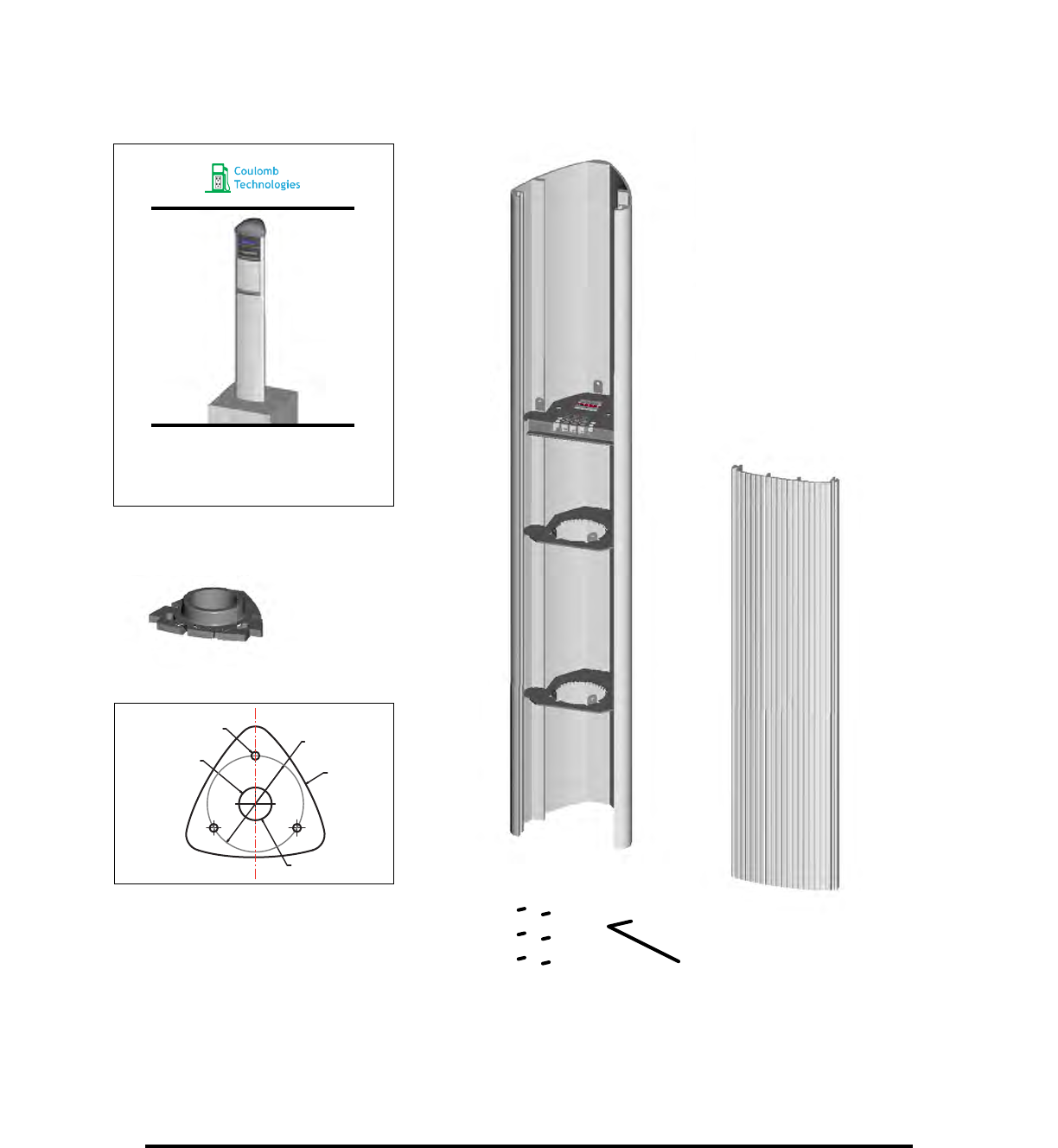
Components and Parts:
Ø
149.20
Ø
12.70
Ø
50.80
FRONT
BOLLARD OUTSIDE ENVELOPE
CONDUIT WITHIN THIS AREA ONLY
Body Installation Kit
(shipped to installer)
Body
Documentation
Base Plate
Base Plate Template
Set Screws (6) Alan Wrench
Slide Panel
Coulomb CT1000 Bollard Smartlet Installation Instructions Revision 0.1 PRELIMINARY

FRONT
BOLLARD OUTSIDE ENVELOPE
CONDUIT WITHIN THIS AREA ONLY
Ø 2.00"
50.79 mm
7.99"
202.96 mm
Ø 0.50"
12.70 mm
Ø 5.87"
149.18 mm
CT1000 Bollard Base Plate Template
Use this template to properly space the J-Bolts and
conduit piping while casting the footing in place. NOT TO SCALE
Coulomb CT1000 Bollard Smartlet Installation Instructions Revision 0.1 PRELIMINARY
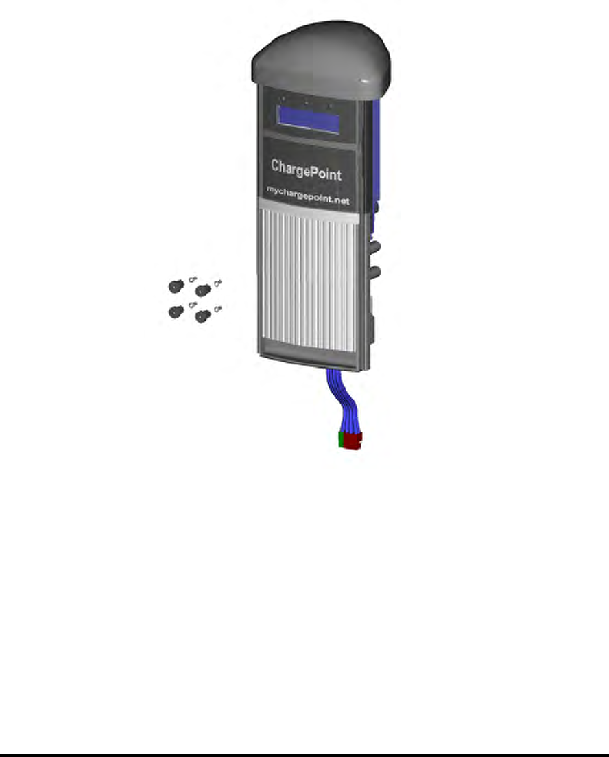
Components and Parts:
Head Module Installation Kit
Head Module
Security Screws
Caps for Security Screws
(shipped to installer)
Required Hardware: (installer supplied)
Torx Driver T15 Torx 3" Blade Length 7-1/2", Tamper Resistant
Coulomb CT1000 Bollard Smartlet Installation Instructions Revision 0.1 PRELIMINARY
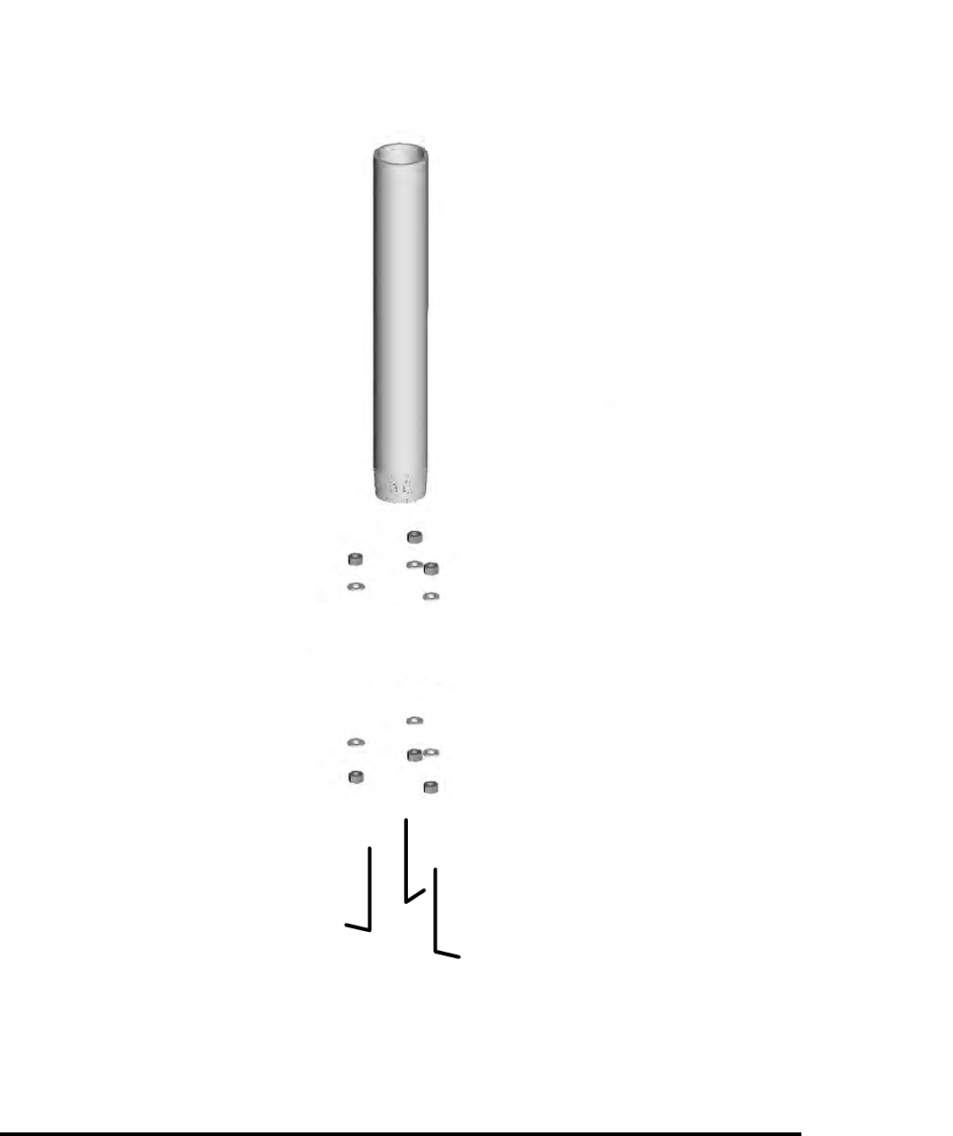
Installer supplied:
1. Schedule 40
Galvanized pipe
3 1/2” OD - 3” ID
24“ Long
2. Nuts and washers
(to match J-Bolts)
3. J-Bolts (Max 1/2” thread dia)
Length to match Local Code
Installer Supplied Components and Parts
Rust Sealer
Coulomb CT1000 Bollard Smartlet Installation Instructions Revision 0.1 PRELIMINARY
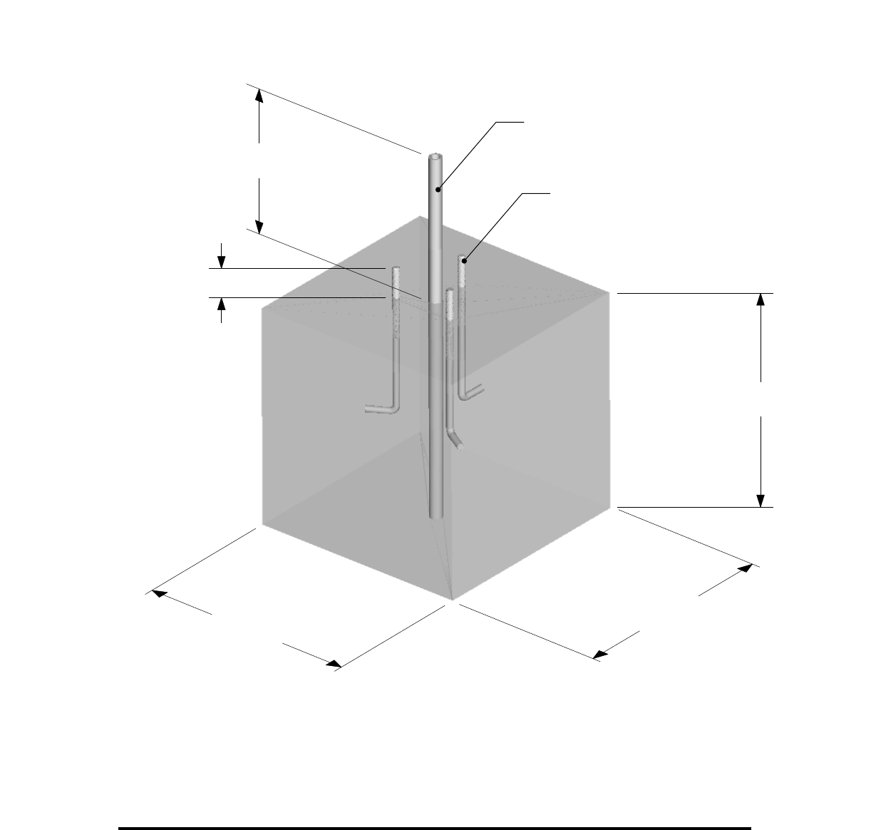
Cast Footing in Place - Concrete 18”x18”x18” or sized to local code
J-Bolts, Washers and Nuts Installer Supplied
18" min
or sized to local code
18" min
or sized to local code
18" min
or sized to local code
2.5" min
12" to 24”
or sized to local code
3 J-Bolts(Installer supplied) - Please use
Base Plate Template
1 1/2” Conduit
Coulomb CT1000 Bollard Smartlet Installation Instructions Revision 0.1 PRELIMINARY
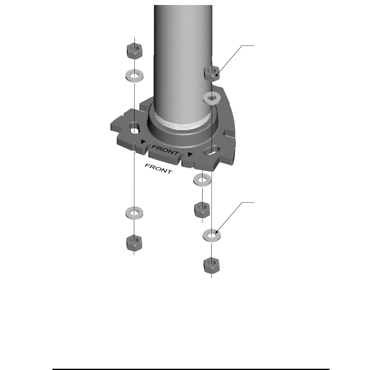
Mount Base Detail
3 Areas for leveling
Nuts and washers
(Installer supplied)
Attach Base Plate to J-Bolts and
tighten screws.
Coulomb CT1000 Bollard Smartlet Installation Instructions Revision 0.1 PRELIMINARY
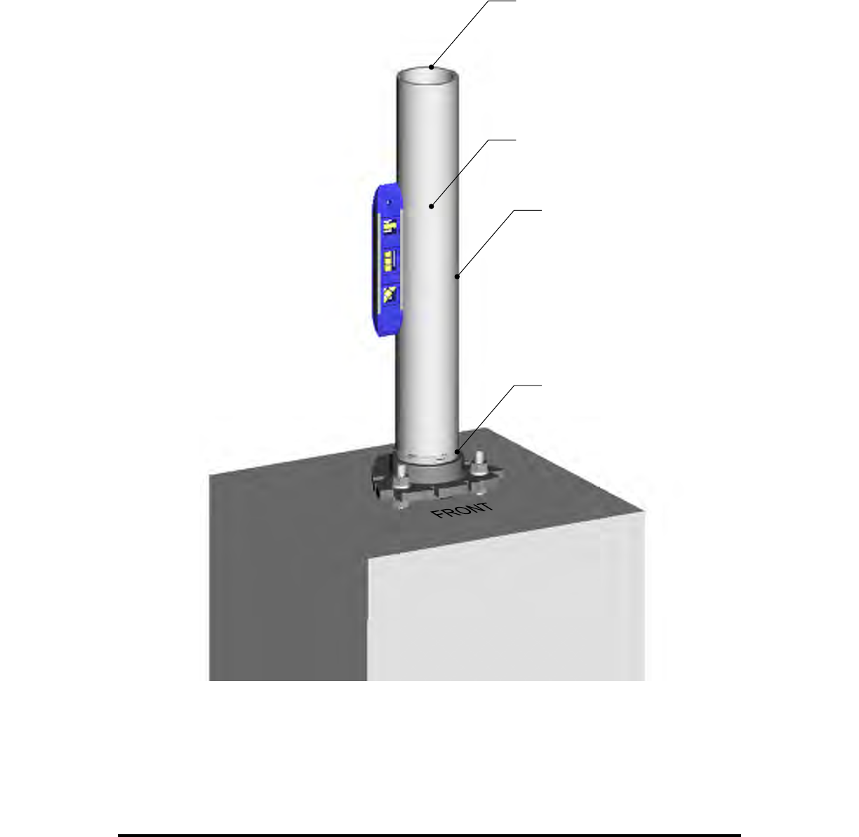
Mount Base Assembly
Schedule 40
Galvanized pipe
3 1/2” OD - 3” ID
24” Long
Installer supplied
Debur top edge
3” NPT, add rust sealer
before installation
Coulomb CT1000 Bollard Smartlet Installation Instructions Revision 0.1 PRELIMINARY
+
-
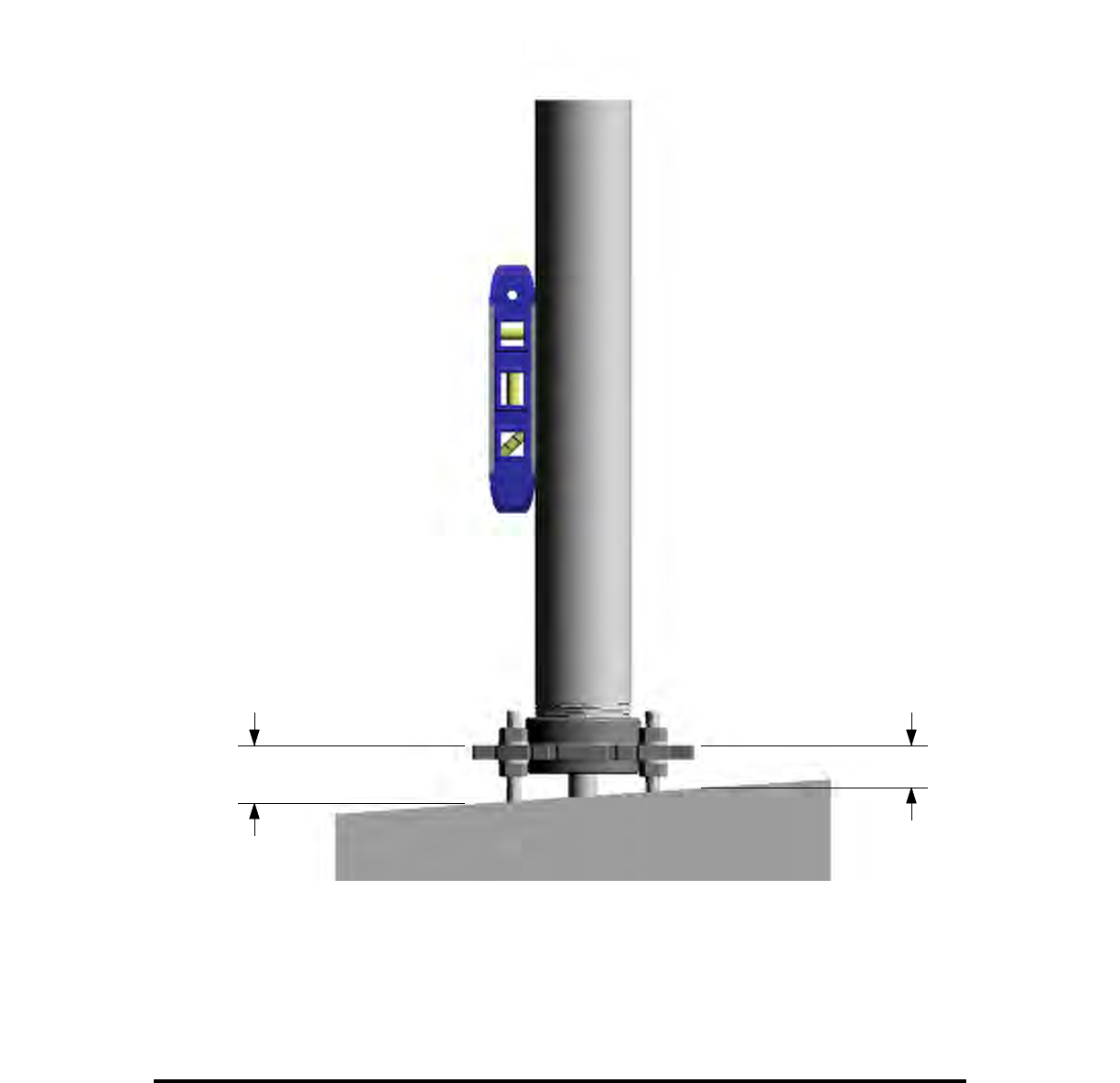
Ensure the piping is plumb.
Add rust sealer before securing in place.
Level Base Assembly
Coulomb CT1000 Bollard Smartlet Installation Instructions Revision 0.1 PRELIMINARY
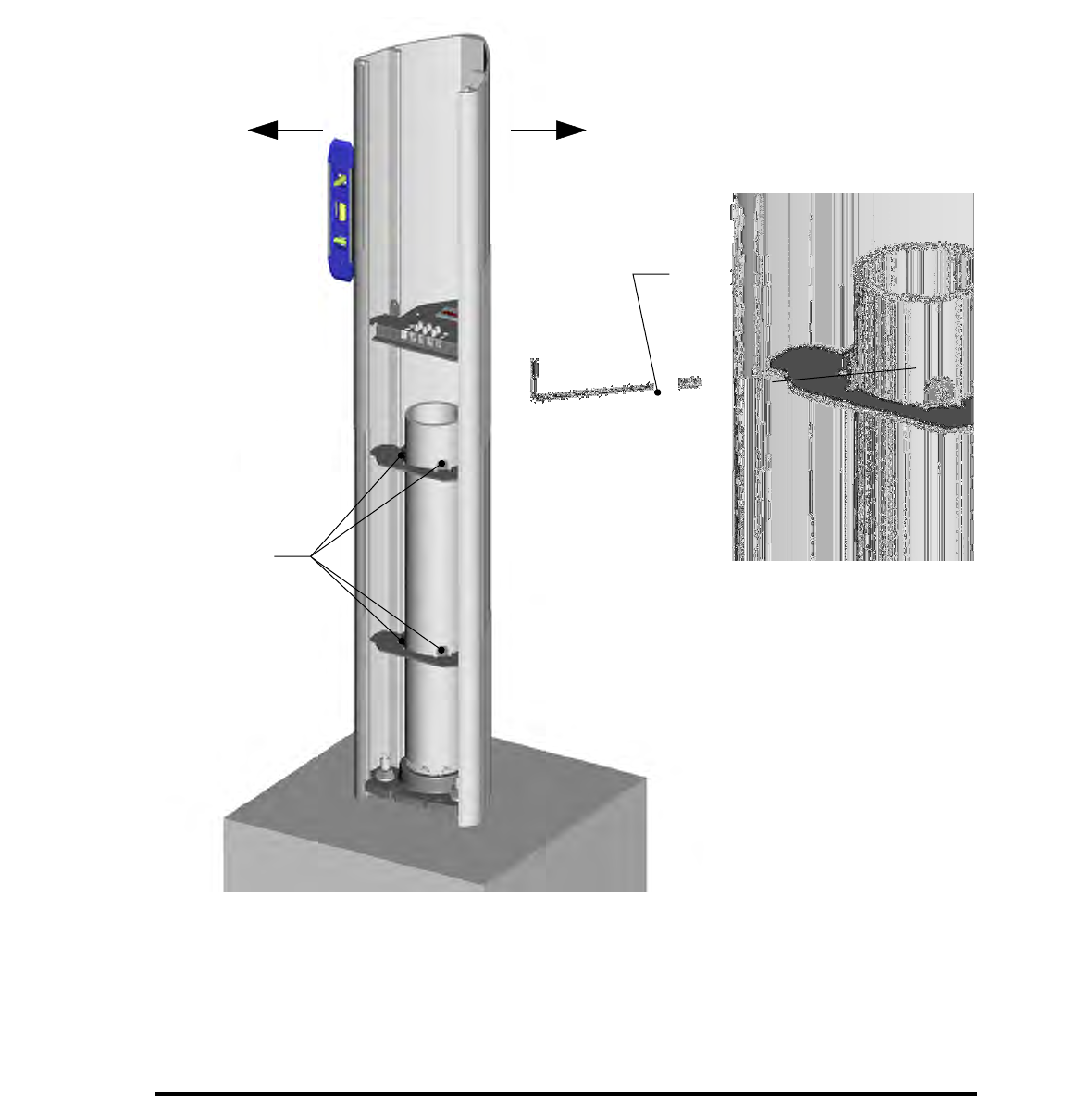
Set screw 4 places
(included)
Alan wrench
(included)
Level Body
Ensure body is level before tightening screws.
Coulomb CT1000 Bollard Smartlet Installation Instructions Revision 0.1 PRELIMINARY
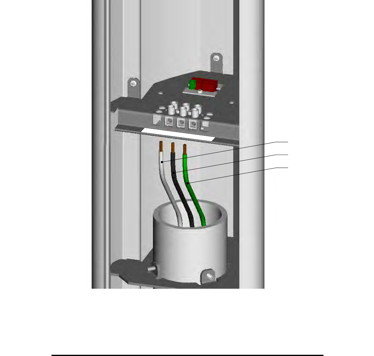
Wire Connection
White
Black
Green
White
Neutral Black
Hot
120vac Input
Requires 15A branch circuit and overcurrent protection on supply
Green
Ground
Strip wires back 3/8".
SOLID WIRES ONLY.
Coulomb CT1000 Bollard Smartlet Installation Instructions Revision 0.1 PRELIMINARY

Wire Connection Label
Use these 3 screws
White
Neutral Black
Hot
120VAC Input
Requires 15A branch circuit and overcurrent protection on supply
Green
Ground
Coulomb CT1000 Bollard Smartlet Installation Instructions Revision 0.1 PRELIMINARY

Wire Connection
Wh
Neutr Black
Hot
1 c Input
Requires 15A ch circuit overcurre otection on supply
G
Gro
White
Black
Green
View after wires are connected and screwed in place.
Coulomb CT1000 Bollard Smartlet Installation Instructions Revision 0.1 PRELIMINARY
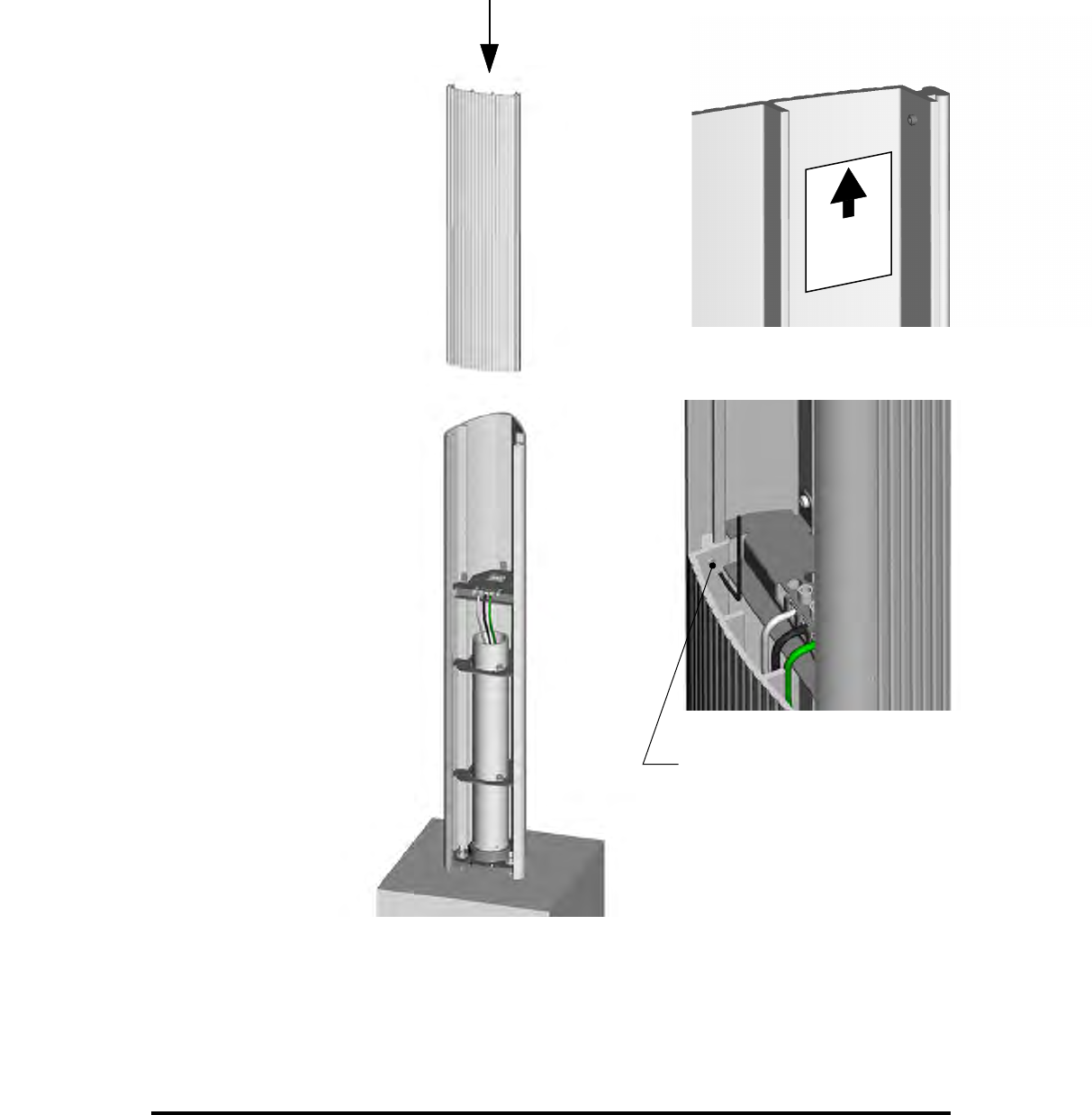
Set screw (2 places)
THIS END
UP
Inside Detail View
Ensure the correct end is up and slide the front panel into the body.
Slide front panel into place and lock with set scres (2 places)
Coulomb CT1000 Bollard Smartlet Installation Instructions Revision 0.1 PRELIMINARY

Front Section
X
!
Coulomb CT1000 Bollard Smartlet Installation Instructions Revision 0.1 PRELIMINARY
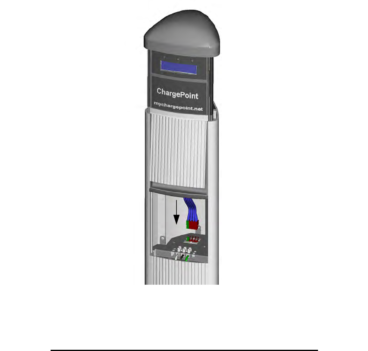
Slide Head Module into Place
Connect the attached cable from the head module with the connectors in the body.
Coulomb CT1000 Bollard Smartlet Installation Instructions Revision 0.1 PRELIMINARY
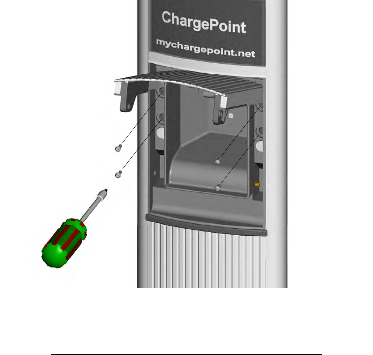
Secure Head Module (4 screws)
Torx Driver T15 Torx
3" Blade Length
7-1/2", Tamper-Resistant
Coulomb CT1000 Bollard Smartlet Installation Instructions Revision 0.1 PRELIMINARY

Secure Cover Plugs for 4 Screws
Coulomb CT1000 Bollard Smartlet Installation Instructions Revision 0.1 PRELIMINARY
Note: This equipment has been tested and found to comply with the limits for a Class A digital
device, pursuant to part 15 of the FCC Rules. These limits are designed to provide
reasonable protection against harmful interference when the equipment is operated in a
commercial environment. This equipment generates, uses, and can radiate radio frequency
energy and, if not installed and used in accordance with the instruction manual, may cause
harmful interference to radio communications. Operation of this equipment in a residential
area is likely to cause harmful interference in which case the user will be required to correct
the interference at his own expense.
Caution: Changes or modifications not expressly approved by the party responsible for compliance
could void the user's authority to operate the equipment.